effectively handle powders - chemical processing · gap mill gm-d for fine grinding the...
TRANSCRIPT

2009
Powder eHandbook
Effectively Handle Powders

2
Table of ContentsRethink High-Temperature Materials Processing 5Take advantage of opportunities to enhance energy efficiency
Convey Hazardous Powders Safely 12Consider these seven key parameters when selecting vacuum conveying technology
Improve Cleanability in Process Weighing Technology 19An innovative solution tackles the challenge of hygienic security
Sensor Puts Sites on Powder Measurements 23Overcome dust and topography challenges when measuring powders in silos and bins
Properly Size Motors for Screw Feeders 29Consider the effect of different material when specifying power requirements
Product FeaturesCleaning Nozzle Available For Reverse Pulse Jet Collectors 2
Gap Mill GM-D for Fine Grinding 3
Dense Phase System Eliminates Extruder Issues 31
Cleaning Nozzle Available For Reverse Pulse Jet CollectorsNew nozzle design adds an additional 12% cleaning flow into the media
SCIENTIFIC DuST Collectors (SDC) offers cleaning technology for reverse pulse jet dust collectors. SDC’s new cleaning nozzle provides cleaning technology at a lower pressure drop. The company utilizes nozzle-based clean-ing systems for reverse pulse jet collectors. Previous nozzle designs provided a 40% increase in cleaning flow when compared to generic venturi-based cleaning systems. SDC’s new nozzle design adds an additional 12% cleaning flow into the media.
SCIENTIFIC DuST CollECToRSwww.scientificdustcollectors.com

3
Ad IndexMarion Mixers 4marionmixers.com
Vac-u-Max 8vac-u-max.com
Fauske 11fauske.com
Sartorius 15sartorius.com/contego
BinMaster 18binmaster.com
Horizon 20horizonsystemsinc.com
Scientific Dust Collectors 22scientificdustcollectors.com
Hapman 25hapman.com
Bauermeister 28bauermeisterusa.com
K-Tron 34ktron.com
Gap Mill GM-D for Fine GrindingTHE BAuERMEISTER Gap Mill is a unique design for grinding most ma-terial down to a fine powder. The design features an adjustable grinding gap between the conical shaped rotor and a corrugated baffle. This combination is said to deliver improved grinding performance and accurate particle sizing in one pass without screens and without internal recirculation. The mill is available in four production sizes, in carbon or stainless steel construction, as well as 10-Bar explosion proof design. For ambient or cryogenic grinding temperatures, depending on the application demands.
BAuERMEISTERwww.bauermeisterusa.com


5
Rethink High-TemperatureMaterials ProcessingTake advantage of opportunities to enhance energy efficiency
By Tom Mroz and Robert Blackmon, Harper International
oPTIMIzING ENERGy efficiency during high-temperature materials processing seems a worthwhile goal to strive for in developing a new production line. But what does it mean? And where do you start? To consider the scope of opportunity for energy efficiency to reduce cost and improve operations, it’s important to pinpoint a few baseline principles.
First, the initial development of an advanced material process usually focuses on the technical value of the product, not the elegance or efficiency of the process. The material’s end physical properties drive development. Energy efficiency gets considered later, when product cost begins to become a significant con-cern. In a worst-case scenario, the production route developed in the laboratory can hinder true efficiency as the process is scaled up to industrial levels.
Second, high-temperature processes are notorious wasters of energy — as exemplified by the hot work-ing environment around steel forges and aluminum smelting pots. Those processes are modest compared to ones for some cutting-edge materials that operate at 2,000–3,000°C. The opportunity for improve-ments in efficiency is great but these come at a cost or a sacrifice.
THIMBlES To ToNS
The road from process inception to commercial production is arduous. Scaling of thermal processes rarely is a simple matter of linear extrapolation.
At experimental scale, the conversion rate of
many solid/solid and solid/gas reactions primarily depends upon the setpoint temperature, overall atmospheric chemistry, size of the reactants and the quality of the intermixing. In small research test furnaces, the furnace temperature can track the control profile very well. The sample load, if relatively small, also may track the desired profile well. At the same time, the small internal volume of the furnace and ratio of sample to furnace volume simplify removing product gases and replenishing with fresh gas. Under these experi-mental conditions, product uniformity is rarely a significant concern.
As the reaction is scaled to larger sizes, the ability to heat or cool the mass of material and introduce or remove gases from the solids plays an increasingly im-portant role in reaction efficiency. Often these factors become the primary variables that control the conver-sion rate. They can create limitations that extend the total processing time, impacting both throughput and total energy utilization.
Moreover, batch processing, if chosen for pro-duction, takes a further, significant toll on energy efficiency. The requirement to heat and then cool the entire product load, the reaction containers, struc-tural components and all the refractories is especially inefficient. In cases demanding higher temperatures and faster heating/cooling rates, water cooling may improve the functionality of the equipment — but at a substantial sacrifice in energy efficiency.

6
MoVING BEyoND BATCH
The most efficient thermal processes are engineered to apply heating and cooling to the smallest load possible. In a perfect situation, this means process-ing the reactants in a continuous manner without need for material containment. The three most criti-cal design criteria that affect efficiency are reactor type, refractory and atmosphere management. So, let’s look at each of these.
Reactor type. During scaleup, it’s crucial to select the most appropriate reactor. Table 1 lists some character-istics of various types of reactors. Each design brings process advantages and challenges. Often a material’s handling characteristics and behavior during process-ing will dictate choice of a certain type of reactor. Additionally, the need to mix material while it’s heated can preclude the use of a reactor where the material is constrained or stagnant.
Furnaces in which boats of material or trays of
components move through on a carrier or car, such as a pusher, roller hearth or mesh belt conveyor, enable production of significant amounts of material but put the ancillaries through the heating and cooling cycle. Frequently, the reaction time or the need for a highly uniform process will mandate using such a system. In some cases, rails or some other form of conveyance can transport containers of material directly through the furnace, eliminating any heating and cooling of support materials; this is much more efficient.
Conveyance furnaces come in a wide variety of designs and materials of construction. The highest efficiency units are ones that recover heat or recir-culate hot containers within the heating zone of the furnace, thereby limiting heating and cooling require-ments almost exclusively to the process material. In more-advanced designs, heat recovery from product carriers can boost system efficiencies further. Some-times, it’s even possible to engineer material flows so
CoMPARISoN oF REACToR DESIGNS
Table 1. These reactor types offer different strengths and weaknesses in relation to some key criteria.
Reactor TypeMaterial Handling
TransportTemperature
RangesResidence Time
RangesVolumetric Efficiency
Gas Solid Interaction
Homogeneity of Reaction
BatchStatic, typically no
movement. Used for net shapes and powders
To 3,000°C Infinite Low Low/difficult Low
Rotary Tube
Via rotating tube and angle of inclination.
Ideal for powder and bulk materials
To 3,000°C 15 to 150 minutesLow
(10–20% filled)
Moderate. Can be
enhancedHigh
Horizontal Slot
Material generally not in contact with furnace.
Ideal for fibers, filaments and webs
To 3,000°CGenerally less than
15 miuntes. Not limited
LowModerate.
Can be enhanced
Moderate
Vertical Tube or Slot
Via gravity or set by rotary valve or auger.
Ideal for powdersTo 3,000°C 15 to 150 minutes High
Moderate. Can be
enhancedLow
Mesh/Strip BeltVia mechanical belt.
Used for powders, bulk materials and net shapes
To 1,200°CUnlimited. Set by belt speed., Ideal
for longer reactionsModerate
Low. Can be
enhancedHighly uniform
Pusher/Roller Hearths
Via transport in saggers. Used for powders, bulk
materials and net shapesTo 3,000°C
Unlimited. Set by push speed. Ideal
for longer reactionsModerate
Low. Can be
enhancedHighly uniform
Fluid BedVia mechanical or gas flluidization. Ideal for homogenous powders
To 1,600°C and higher
Generally less than 2 hours High High
Mixed results. Non-uniformity
can occur. Generally gaussian
distribution
7
cool incoming reactants get preheated by exiting ma-terial. However, these designs are less common and can pose design and operational difficulties. Nonethe-less, they can provide the best efficiency for processes demanding container-supported heating.
Gaining much more energy efficiency requires eliminating the need for containered material conveyance altogether. One option is a rotary tube furnace. As the reactant bed moves through the tube, it’s constantly stirred by the tube rotation. This stirring action boosts thermal transfer to the bed, improves removal of product gases, and increases solid/gas exchange in cases where the furnace gas also is a reactant. These enhancements often lead to product with better uniformity than materials processed in a static bed. Additionally, because only the reactant powder is heated and cooled, thermal efficiency is significantly better than that of pusher-style furnaces.
Vertical furnaces offer a reasonable alternative to rotary tube furnaces in cases where material movement in the rotary furnace is unsatisfactory or where other
features such as very short or very long lead times, significant interaction with reaction atmospheres or completely contact-free reactions are required. Simi-lar to rotary furnaces, energy use primarily is related to heating of the product and supporting necessary reactions and, thus, is relatively efficient. The design allows for minimal interaction with the furnace wall, making it a good choice where contamination is an issue. In some cases, this type of furnace is invaluable in combination processes, e.g., spray pyrolysis coupled with calcining.
Refractory. The selection and design of refractory can significantly impact thermal efficiency. In batch sys-tems, highly efficient refractory designs may save energy and boost ramp speed during heatup and soaks but lead to extended cooling times and, thus, longer total cycle times. Less efficient designs may improve the cooling rate but pose shell-temperature or other limitations. Alternatively, water-cooled equipment may provide a reasonable solution for cooling rate and minimize space and weight requirements for refractories — but will dramatically decrease energy efficiency.
120
110
100
90
80
70
60
50
40
30
20
10
0
Ene
rgy
Co
nsum
ptio
n, k
Wh/
kg
Production Rate, mt/yr
1m wide
Max (with recuperation) Total line load Nominal consumption (with recuperation)
2m wide 3m wide
0 500 1,000 1,500 2,000 2,500 3,000 3,500 4,000
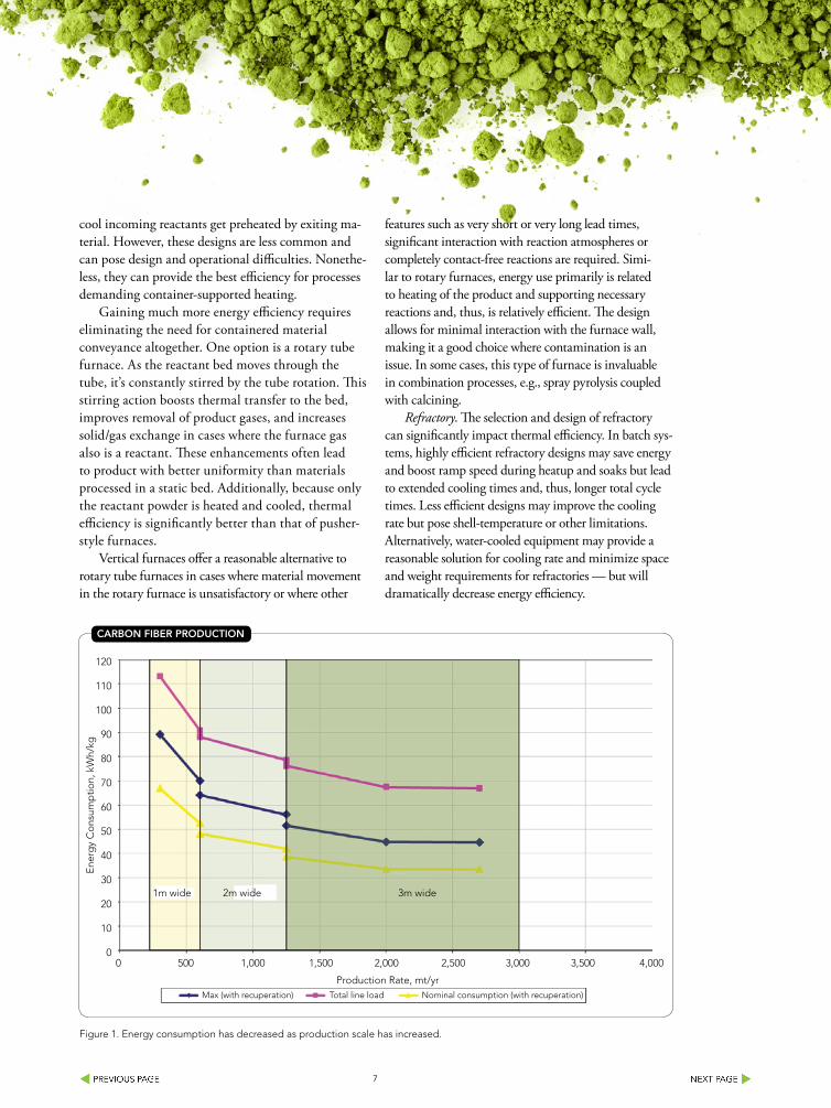
CARBoN FIBER PRoDuCTIoN
Figure 1. Energy consumption has decreased as production scale has increased.

8

9
Continuous processes decouple the heating, soak and cooling portions of the process by distance. Therefore, using different refractory designs along the length of the furnace can optimize the thermal management and thermal efficiency requirements in each stage.
Atmosphere management. Heat losses via exhaust designs also significantly differ between batch and continuous equipment. The ability to utilize waste heat generated by batch furnace exhausts is limited. Because the waste heat in such equipment essentially is at the temperature of the load, there’s no opportu-nity to insert the heat value directly into the process.
In contrast, continuous processes routinely provide a variety of options for heat recovery. For instance, counterflow gas can help cool product leaving the process and subsequently help preheat the incoming reactants. Also, gas composition at a given position in the furnace is more predictable. In cases where incoming gas chemistry or removal of gaseous products influence the reaction rate, this predict-ability enables minimizing gas usage and, therefore, thermal losses related to the gas.
Where the exhaust gas contains waste products having fuel value, advanced equipment design can combust the gas and use the hot stream for preheating the primary process. In some cases, such waste-gas streams can provide very substantial fractions of the total thermal requirement for a process. The result is significant energy efficiency and reduced associ-ated costs, as well as lower costs and environmental concerns compared to alternatives for abating the waste-gas flow.
INSIGHTS FRoM CARBoN FIBER
Conversion of polymeric fiber materials to carbon fiber typifies how processes evolve. Large-scale production of carbon fiber began in the 1970s. Initial equipment was less than 1,000-mm wide and produced under 100 tons per year — and required an input of 150–200 kWh per kilogram of carbon fiber.
Through successive scaleup efforts, the state-of-the-art for conversion of carbon fiber now has advanced to a system width of 3,000–4,200 mm and single-facility production rates exceeding 2,500 tons per year. Through increased reuse of energy (integration of waste energy to drive the process), equipment improvements (via economies of scale and refractory advancements) and better basic feed material (polymers with higher conversion to carbon fiber), the specific energy con-sumption is now less than 20 kWh per kilogram of car-bon fiber. Figure 1 highlights the progressive reduction of energy requirements through the scaleup process.
In many ways carbon fiber production can serve as a useful guide for improving the efficiencies of other thermal processes. Polyacrylonitirle-based carbon fiber production is performed in an entirely container-less mode; the fiber itself provides the motive force to move the product through subsequent process steps. This provides the energy efficiency of a continuous process, augmented by further gains from eliminating the need to heat ancillary support equipment. The only system inefficiency is the heat loss related to the cover gas used to maintain the appropriate atmosphere. Develop-ment efforts to reduce this atmosphere loss through improved furnace end seals are ongoing.

10
PRoCESSING oPPoRTuNITIES
Most thermal processes involve bulk materials in the form of powders or aggregated mixtures that require some type of container or construct, such as a belt conveyor or rotary tube, to assist in material trans-port through the process. Minimizing the energy losses associated with this aspect of the equipment design is one of the most significant opportunities for improving energy efficiency. Design optimiza-tion often involves concern for this energy efficiency in concert with considerations for enhancing reac-tion kinetics, gas exchange, residence time and ma-terials of construction. Therefore, the requirements related to a specific process will drive the options for production methods and, thus, the efficiencies of that process.
In practice, rotary tube furnaces provide notable values of throughput and efficiency for a wide range of powders, as long as the materials behave properly during the process. In some cases, the nature of the reactant material can cause flow problems. Powder adhesion to the tube can change bed mixing behavior, flow through the furnace and, in extreme cases, cause wide swings in material residence time. In other cases, material entrain-ment in the exhaust gas can affect throughput and flow. Sometimes changing the reactants’ physical form — e.g., granulating fine powders into pellets or aggregates — can overcome these problems. Alternatively, the use of internal features within the process tube can promote desired bed behavior. When the nature of the mate-rial doesn’t allow for granulation or the granules aren’t sufficiently strong to retain their shape throughout the
process, other means of high throughput and high ef-ficiency processing are needed.
EMERGING oPPoRTuNITIES
Recycling the process heat from the product dur-ing cooling promises to further enhance energy efficiency. Transferring that heat to incoming reactants means less energy must be inserted into the process. It also can foster more-compact designs because the equipment’s heating and cooling portions may be shorter and the heating elements and support equipment may be smaller. Introducing this form of energy efficiency into bulk materials processing equipment is still in its early stages. However, equipment designs that provide this type of heat transfer for select processes have been demonstrated and additional opportunities to expand the concept to a wider range of materials are being investigated.
Empirical testing at a demonstration semi-contin-uous level provides a proven means to extract scaleup parameters. Scaleup data from a well-designed set of experiments on semi-continuous or continuous furnac-es can serve to redefine the process recipe and identify the continuous commercial-scale device that provides the best balance between product quality, throughput, energy efficiency and operating expenses.
ToM MRoz is director of technology for Harper International,
Lancaster, N.Y. RoBERT BlACKMoN is vice president of
integrated systems for Harper International. E-mail them at tmroz@
harperintl.com and [email protected].


12
Convey Hazardous Powders SafelyConsider these seven key parameters when selecting vacuum conveying technology
By Sharon Nowak, K-Tron
THE FINE chemical and pharmaceuti-cal industries process thousands of very expensive dry bulk materials every hour of every day for a variety of applications. To maintain the highest standards of safety, sustainability and hygiene, it’s essential that these powders are moved from process to process without any danger to the opera-tives, damage or exposure of the product to the atmosphere, or loss of valuable product within the process stream.
SEVEN KEy PARAMETERS
When moving powder from process to process in these industries, several crucial factors must be addressed to ensure an acceptable solution. The method of mov-ing powders in an enclosed stream of air or nitrogen is commonly known as vacuum conveying and the technology for this form of transport has evolved to meet the arduous demands of these markets (Figure 1).
Typically, there are seven key goals which the end user, in conjunction with the equip-ment supplier, should consider when address-ing the use of vacuum conveying.
1. Maximize Product Containment for Toxic/Costly Ingredient Powder Transfer: The system used to convey toxic and highly expensive powders must eliminate any possi-bility of the powder leaking into the working environment.
2. Maximize Product Yields: All powder leaving one process should be transferred to the next process with an absolute minimum of retained powder.
3. Minimize Product Segregation and Attrition: Low-velocity, dense phase systems are possible when using vacuum and this type
of system minimizes product degradation and also eliminates product segregation when conveying products that have undergone a mixing or blending cycle.
4. Optimize Cleaning Cycles in Sanitary Powder Applications: All equip-ment used in the transfer of powders must be capable of being very thoroughly cleaned. A variety of cleaning techniques and designs are available for consideration.
5. Optimization of the Overall Process through Integrated Systems Design: For economic reasons, it’s beneficial if powder transfer can be integrated into a duplicate process such as air-swept sieving or air-swept milling. This integration simplifies the pow-der handling and helps to increase efficiency on the secondary process.
6. Ease of Operation: The powder con-veying equipment should be simple to operate and easily integrate into the process for ease of control and in the case of pharmaceutical applications, overall validation. Options are available for a wide variety of product delivery and pickup.
7. Optimization of Safety: Inert gases such as nitrogen are very easy to introduce into a vacuum system thus ensuring the elimination of oxygen and a consequently safe system with no danger of explosion.
PARAMETER 1:
ElIMINATE lEAKAGE
Vacuum conveying meets many of these criteria because the negative pressure inside the vessels and pipe work precludes any powder leakage to the atmosphere. A typi-cal vacuum conveying system is fully sealed with the entrained powder contained in
Figure 1. Standard-design vacuum receivers can help manufacturers maintain high safety, sustainability and hygiene standards in powder processing operations.

13
a sealed container attached to the process device (see Figure 2). In the case of highly toxic powders, the additional use of split butterfly containment valves can be incor-porated to maintain specific hazard levels.
During the vacuum process, the vacuum or suction is generated by means of a vacuum pump. The vacuum in the pickup source is initiated and material flows from its source directly to the sealed container or receiver. After the receiver is filled to the re-quired capacity (usually detected by means of a level indicator), the vacuum breaks. Material settles within the receiver. Upon request of powder from the process below, such as in the drum filling operation shown (see Figure 3), the valve at the bottom of the receiver opens and product is delivered to the process. Shortly thereafter a pulse of air is sent through the filters housed within the collection receiver to clean the filters of any residual material. This also aids in maximiz-ing overall yields (see parameter 2).
The introduction of powders that are not free flowing to the vacuum system can be “assisted” by a range of flow aids such as vibration, fluidization, or aeration pads.
These devices are located into a steep-sided vessel, which also encourages the powder to flow to the entrainment point where the air and powder are mixed ensuring a smooth transfer through the convey line.
PARAMETER 2:
MAxIMIzE PRoDuCT yIElDS
The speed of the air movement in a well-designed vacuum conveying system ensures that the powder cannot settle in the pipe line, thus ensuring that no residue remains. In addition, at the very end of the run, line-clearing valves can be used to en-sure that any remaining material is cleared into the receiver prior to dismantling the unit for cleaning.
Design of the vacuum receiver with reverse jet filters and steep discharge cone angles, or sometimes straight cylindri-cal walls, also encourages the free flow of powders from the receiving hopper into the next process. The more difficult-to-handle powders are encouraged to flow with vari-ous flow aids such as vibrators and varying degrees of fluidization. Filtration is crucial when handling fine powders.
Figure 3. In this drum filling operation, the valve at the bottom of the vacuum receiver opens and product is delivered to the process.
Figure 2. Vacuum receiver integrated with powder handling maximizes containment to prevent material leakage to the atmosphere.
14
Modern filter materials, such as PTFE-laminated polyester, are designed to have high-release character-istics that ensure the filter doesn’t allow the passage of fine particles and that residual material is removed during the filter clean cycle. Well-designed vacuum hoppers have all welds ground smooth and are de-signed to be crack and crevice free with a high degree of polish.
PARAMETER 3:
MINIMIzE PRoDuCT SEGREGATIoN
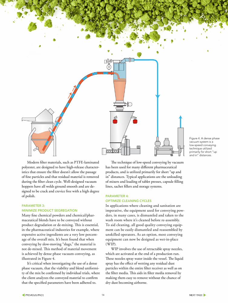
Many fine chemical powders and chemical/phar-maceutical blends have to be conveyed without product degradation or de-mixing. This is essential, in the pharmaceutical industries for example, where expensive active ingredients are a very low percent-age of the overall mix. It’s been found that when conveying by slow-moving “slugs,” the material is not de-mixed. This method of material movement is achieved by dense phase vacuum conveying, as illustrated in Figure 4.
It’s critical when investigating the use of a dense phase vacuum, that the viability and blend uniformi-ty of the mix be confirmed by individual trials, where the client analyzes the conveyed material to confirm that the specified parameters have been adhered to.
The technique of low-speed conveying by vacuum has been used for many different pharmaceutical products, and is utilized primarily for short “up and in” distances. Typical applications are the unloading of mixers and loading of tablet presses, capsule filling lines, sachet fillers and storage systems.
PARAMETER 4:
oPTIMIzE ClEANING CyClES
In applications where cleaning and sanitation are imperative, the equipment used for conveying pow-ders, in many cases, is dismantled and taken to the wash room where it’s cleaned before re-assembly. To aid cleaning, all good quality conveying equip-ment can be easily dismantled and reassembled by unskilled operators. As an option, most conveying equipment can now be designed as wet-in-place (WIP).
WIP involves the use of retractable spray nozzles, which are activated at the end of a production run. These nozzles spray water inside the vessel. The liquid spray has the effect of wetting any residual dust particles within the entire filter receiver as well as on the filter media. This aids in filter media removal by making them easy to remove without the chance of dry dust becoming airborne.
Figure 4. A dense phase vacuum system is a low-speed conveying technique utilized primarily for short “up and in” distances.

15
Contego® – The clean solutionMore hygiene for your process vessel weighing
The innovative weighing module is the solution for hygienic applications.
Designed according to EHEDG directives
Quick and reliable cleaning
High chemical resistance
Compact design
Integrated lift-off protection for high stability
Allows standardized installation solutions
Reduces design work
Sartorius Mechatronics Corporation5 Orville Drive, Suite 200Bohemia, NY 11716
Phone +1.866.963.8587 Fax [email protected]
www.sartorius.com/contegoturning science into solutions
Ad-Contego_7x10inch_e.indd 1 03.08.12 11:06

16
In some specialized receiver designs, the top sec-tion of the receiver can be swung away and the filter elements withdrawn and taken away for intense clean-ing. The remaining section of the system is then thor-oughly cleaned and dried before reuse. The swing-out head feature of the filter receiver also is helpful in areas where headroom is an issue, because the filters in this case are removed from below, as opposed to above the filter receiver (see Figure 5). Further design options incorporate lift mechanisms for the complete filter receiver assembly to facilitate the overall clean-ing and dismantling procedures, thus shortening and optimizing overall cleaning cycle times.
PARAMETER 5:
oPTIMIzATIoN oF THE oVERAll PRoCESS
One of the major advantages of a vacuum conveying system is that it’s very easy to introduce a secondary process into the initial transfer process. For example, when base raw materials arrive in bags or paper sacks, it’s essential that they are screened before entering the manufacturing process. This is achieved by simply introducing a sieve into the convey line. Powder is conveyed from the sack or bin and as it passes through the screen any oversize particles or foreign matter are trapped on the stainless mesh. The acceptable powder passes through the mesh and continues on to the next phase of the process. The flow of air through the mesh helps to keep the mesh clean and often increases the efficiency of screening compared to gravity screening where there’s no ad-ditional air flow.
A similar technique can be used with conical screen mills which are often used to de-lump the material coming from the powder source and prior to introduction to the process. The conical screen mill is placed in between the product pickup point and the vacuum receiver, with the effect of material being drawn through the mill with a stream of fast flow-ing air. Operation of the conical screen mill under vacuum has the added advantage of reducing overall residence time within the mill, thus also reducing any added attrition that may occur in the process.
An added advantage to air-swept milling is the ability to use nitrogen as the conveying gas. This makes the system safe because the mill can often be considered a source of ignition if the material being
milled is potentially explosive. It’s important to note that although most mills and sieves are able to operate under the fairly low level of vacuum required, the use of vacuum with the mill or sieve in question should be addressed with the equipment manufacturer to ensure that the proper seals or gaskets are in place to ensure a dust-free operation.
PARAMETER 6:
EASE oF oPERATIoN AND INTEGRATIoN
Due to the availability of a variety of product sources — drums, bags, bulk bags, intermediate bulk containers (IBCs), and flexible intermediate bulk containers (FIBCs) — it’s imperative that the vacuum system utilized be easily integrated into the product pickup method. Sack tip stations complete with integrated vacuum pickup points, as well as IBC docking stations with the same type of pickup hoppers are available from most systems-orientated vacuum conveying manufacturers.
In addition, for contained conveying, specialty dump stations or pick up hoppers with gloveboxes also can be provided (see Figure 6). Typical connec-tion points are via simple clamp arrangements for ease in assembly. For sanitary applications, devices usually incorporate some type of spray ball assembly for cleaning, as well as a drain in the pickup device for drainage.
Figure 5. This vacuum receiver features a swing out filter head that allows easy removal of filter elements for cleaning and fits into areas where headroom is an issue.

17
PARAMETER 7:
oPTIMIzATIoN oF PRoCESS SAFETy
Many fine chemicals and pharmaceutical powders have a low minimum ignition energy (MIE). This is a measure of how easily the powder dust cloud can ignite by any source of ignition. A generally accepted measure of explosive potential for the powder being conveyed is an MIE of less than 10 millijoules; when this occurs a method of dealing with this explosive potential must be designed within the system.
Sources of ignition can vary including static sparks, metal impact by a fast rotating item, hot particles from dryers, or faulty electrical items. Any of these sources coming into contact with a potentially explosive dust cloud can create an explosion. The severity of the explosion is measured by the KST value but even a mild explosion must be avoided. There are typically three methods of dealing with a potential explosion in powder operations. (It should be noted that explosion suppression is not listed as there’s a strong possibility of tripping the suppression system and introducing the suppressant to the batch, thus eliminating it as a good choice for many systems.)
The three most common methods of explosion sup-pression are the following:
Explosion Containment: Equipment must be made strong enough to contain the explosion when and if it occurs. Due to the strength of the required design, this can be a very difficult and expensive solution to implement.
Explosion Venting: This method builds in a burst-ing disc which ruptures at a very low pressure rise and allows the explosion to be vented through a duct to an external wall. The main problem with this technique is finding an external wall close to the equipment, as the distance of the vent and vent duct to the point of igni-tion is critical in the design.
Inerting: Of the three options, this is the easiest and least complex to implement. This method simply replaces air with nitrogen as the conveying gas. The elimination of oxygen prevents an explosion from occurring because the third leg of the fire triangle has been removed. It’s a very simple procedure to connect a nitrogen supply to the suction lance on a vacuum conveyor. Nitrogen consumption is relatively low since the nitrogen only flows when the system is operating on the convey cycle.
oN THE MoVE
The use of vacuum conveying in the fine chemical and pharmaceutical industries for powder transfer is a viable choice that addresses a wide variety of process requirements. The range of vacuum convey-ing techniques is evolving continuously, offering new solutions to major manufacturers who are moving more and more to continuous processes. The ability to move small amounts of powder in a clean, contained manner as well as the inherent process advantages (safety to operator and product) and increases in pro-cess efficiency make vacuum conveying via negative pressure the optimal material handling solution.
SHARoN NoWAK serves as K-Tron’s global business develop-
ment manager for the food and pharmaceutical industries. She can
be reached at [email protected]
Figure 6. This bag dump station from K-Tron features an integrated glove box with bottom pickup for contained conveying.

18
• Multiple-point measurement
• Detects and maps uneven surfaces
• Creates visual repre-sentation of contents
• Works reliably in dusty environments
• Self-cleaning, minimal maintenance
Non-Contact, Dust-Penetrating Level and Volume Measurement
www.binmaster.com [email protected] 800-278-4241 402-434-9102
3DLevelScannerUnsurpassed Inventory Accuracy
MVL Multiple-Scanner System
3DMultiVision Software
Monitor all your bins in a single window from a PC
Accuracy in large bins of powders and solids

19
Improve Cleanability in Process Weighing TechnologyAn innovative solution tackles the challenge of hygienic security
By Matthias Rehren and Matthias Hasselmann, Sartorius
THE FooD and pharmaceutical industries are known for high standards regarding hygiene in the production process. Many sensitive areas, from de-livery to packaging and distribution are located next to one another, making it particularly challenging to combine precise measurement results with compli-ance to hygiene requirements.
In the food industry, the stipulations set out by the European Union (EU), EHEDG (European Hygienic Engineering & Design Group), HACCP (Hazard Analysis and Critical Control Points), the Machinery Directive (Directive 2006/42/EC on machinery) and IFS (International Food Standard), among others, re-quire that equipment is easy to clean in order to avoid microbiological contamination. On the other hand, in the pharmaceutical industry these requirements are regulated by FDA standards or EU good manufactur-ing practice (GMP) guidelines. To ensure the most hygienic production environment possible, a combina-tion of two targets must be pursued: system technol-ogy that’s aimed at meeting hygiene requirements, and correspondingly adapted cleaning management.
The most critical requirements are those regarding components of machines and systems which come directly into contact with the product. These must have a high level of corrosion resistance, must not give off any chemical substances and will ideally have surfaces that have been optimized for ease of clean-ing. As all substances that are processed in a factory may, in the splash zone, also come into contact with parts that have indirect contact with the product, these parts must also be designed in such a way that the risks of contamination are reduced to the greatest possible extent.
Even the most hygienic system is dependent upon regular and careful cleaning. This may be done in various different ways, including: mechanically dry,
mechanically wet or chemically wet cleaning.Depending on the type of contamination (e.g.
flour, cocoa, egg white, fat), system components must withstand methods such as compressed air, suction, fluids or water, or steam blasting. For this to be the case, high-quality materials, such as stainless steel or highly resistant plastics, are used. These offer effective protection against dust and moisture and typically fulfill at least the IP65 standard. In the design of such modules, it’s essential to ensure that the surfaces are sloped and feature low roughness. In the field of weighing, in addition to hygienically optimized platform scales, this also applies to components for container weighing. The greatest challenge here is achieving precise measurement results with simultane-ous implementation of hygiene criteria in the design.
CuRRENT INSTAllATIoN SoluTIoNS
The PR 6202 pressurized load cell from Sartorius is specially designed for use with medium to large containers and has a nominal load of 1t to 50t. Its housing is made of high-quality AISI 316L stainless steel (1.4404), which means that the formation of hygienically critical areas is avoided and cleaning times are thus reduced. The EHEDG-compliant load cell is characterized by smooth run-off surfaces, which make cleaning easy.
Together with the PR 6002 mounting kit, this model is ideal for use in hygienically challenging envi-ronments. This combination impresses here, especially through its high corrosion resistance and compliance with the highest protection class, IP 68/69k. The load cell and mounting kit have both been issued with an expert’s report from the EHEDG, which confirms the fulfillment of hygienic requirements.
According to current hygienic solutions such as the PR 6202, other approaches can achieve higher

20
At Horizon Systems, we understand it is our job to be the strong links in your process line. Our team’s personal approach with clients focuses on resolving your issues to improve plant performance and increase profitability.
Our strength is a result of over 180 years of our team’s collective industry experience that enables us to effectively inter-face and link the anchor equipment in your process for optimum line performance.
The link Toyour maTerial handling success
Bulk Material Handling & Processing • Batching & MixingProcess Controls Technology • System Consultation & Training
Project Management • Aftermarket Service & Support
Discover what solutions we have on your horizon.1-877-779-6176 (toll free) • www.horizonsystemsinc.com

21
resistance and better cleanability in container weigh-ing. For example, in the pharmaceutical industry, load cells are housed in stainless steel sleeves, known as elephant feet. These are intended to offer protection against dust and fluids and enable simple cleaning from the outside. However, this solution involves much cost-intensive design work, even in the plan-ning phase. Furthermore, this installation solution does include some gaps, as the entire weighing system must be free from force shunts in order to achieve a high degree of measuring accuracy. This, however, represents a risk of contamination. While it may ap-pear clean from the outside, pockets of contamination may form on the inside.
HyGIENIC CoNTAINER WEIGHING oVERHAulED
For small- to medium-size process containers, Sartorius offers an innovative solution which is said to bring groundbreaking changes to hygienic container weighing. A completely new module has been developed for containers with a total load of 100kg–8t, which combines the load cell and mounting kit in one hygienic weighing solution. The Contego module is easily installed under the foot of the container, which means that a separate structure isn’t necessary. A 6.6-in. diameter offers a space-saving installation solution. This module combines everything required for hygienic weigh-ing and easy cleaning.
The head and base plates are made of stainless steel AISI 316 L (1.4404). They protect all central components against corrosion and offer an extremely hygienic and stable solution for attachment to the container and base element. An integrated jack-up function provides simple and correct lifting or lower-ing of the container during maintenance work with-out the need for additional tools. As a special element for stabilizing the container, this weighing solution has an integrated lift-off protector and a constrainer. These ensure reliable stability of the container dur-ing operation. If the floor is sealed with silicone, an optional adapter plate is directly cast as well, which prevents the risk of dirt accumulating.
The casing is a sleeve made from FDA-compliant
special silicone, which is also approved for the phar-maceutical industry, and offers the highest levels of hygienic security. It’s securely connected to the head and base plates through a special geometric seal and thus avoids the formation of gaps which can cause contamination. This protective casing also has high chemical resistance to most cleaning agents.
As this weighing solution is used primarily in sensitive production areas, great importance was placed on the precision of measurement results during development. The module is therefore available in ac-curacy classes D1 and C3 and possesses a correspond-ing OIML-compliant type approval.
Overall, the advantage of this weighing solution lies in its impressive hygienic properties, combined with significant cost savings in planning, design and operation. The Contego is available in two differ-ent versions — with the cable outlet on the side or on the top and has an appropriately hygienic cable connection. The conformity of the module has been confirmed by certification from the EHEDG. Both load cell models are naturally available as an explosion-proof version suitable for use in potentially explosive areas.
For connecting the weighing technology to field bus control, a transmitter in the field housing can be used, such as the PR-5230. This consists of an electro-polished stainless steel housing in accordance with IP 66, a graphical display as well as various different communication interfaces. For ease of configuration, a PC connection is provided via Ethernet TCP/IP and an integrated web server. Optionally, a connection card can also be used, which means that an additional cable connection box isn’t necessary. An intrinsically safe load cell supply for use in potentially explosive areas also can be integrated.
With special load cells and a unique transmitter concept, Sartorius offers a range of products tailored to the requirements of the pharmaceutical and food industries. The hygienically optimized weighing technology offers significant advantages with regard to risk of contamination and cleanability. Plant engi-neers and manufacturers are now able to fulfill more demanding standards in these areas.

23
Sensor Puts Sites on Powder MeasurementsOvercome dust and topography challenges when measuring powders in silos and bins
By Jenny Nielson Christensen, BinMaster Level Controls
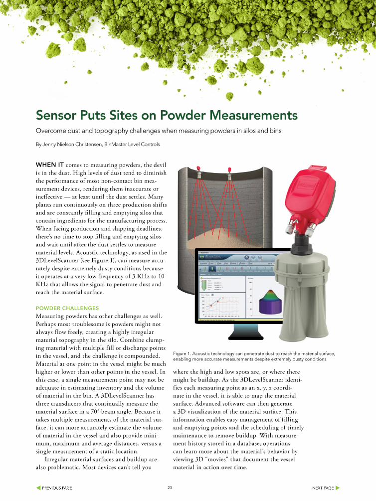
WHEN IT comes to measuring powders, the devil is in the dust. High levels of dust tend to diminish the performance of most non-contact bin mea-surement devices, rendering them inaccurate or ineffective — at least until the dust settles. Many plants run continuously on three production shifts and are constantly filling and emptying silos that contain ingredients for the manufacturing process. When facing production and shipping deadlines, there’s no time to stop filling and emptying silos and wait until after the dust settles to measure material levels. Acoustic technology, as used in the 3DLevelScanner (see Figure 1), can measure accu-rately despite extremely dusty conditions because it operates at a very low frequency of 3 KHz to 10 KHz that allows the signal to penetrate dust and reach the material surface.
PoWDER CHAllENGES
Measuring powders has other challenges as well. Perhaps most troublesome is powders might not always f low freely, creating a highly irregular material topography in the silo. Combine clump-ing material with multiple fill or discharge points in the vessel, and the challenge is compounded. Material at one point in the vessel might be much higher or lower than other points in the vessel. In this case, a single measurement point may not be adequate in estimating inventory and the volume of material in the bin. A 3DLevelScanner has three transducers that continually measure the material surface in a 70° beam angle. Because it takes multiple measurements of the material sur-face, it can more accurately estimate the volume of material in the vessel and also provide mini-mum, maximum and average distances, versus a single measurement of a static location.
Irregular material surfaces and buildup are also problematic. Most devices can’t tell you
where the high and low spots are, or where there might be buildup. As the 3DLevelScanner identi-fies each measuring point as an x, y, z coordi-nate in the vessel, it is able to map the material surface. Advanced software can then generate a 3D visualization of the material surface. This information enables easy management of filling and emptying points and the scheduling of timely maintenance to remove buildup. With measure-ment history stored in a database, operations can learn more about the material’s behavior by viewing 3D “movies” that document the vessel material in action over time.
Figure 1. Acoustic technology can penetrate dust to reach the material surface, enabling more accurate measurements despite extremely dusty conditions.

24
The 3DLevelScanner has been installed in over 400 opera-tions in North America and in some very challenging applica-tions. Each and every installation has its own set of nuances, unique operational concerns, and data needs for decision making. While it can’t solve every level measurement problem at every facility, the 3DLevelScanner has proven to work again and again where plants have found no other acceptable level and volume measurement solution.
AluMINA PoWDER APPlICATIoN
Alumina powder is an extremely dusty material with a bulk density of about 18 lb/ft3. When the vessel is filled it generates huge amounts of dust that never settles as the operation runs continuously 24-7. The plant had tried many devices without success. The carbon steel and concrete bins were about 65 feet in diameter and about 70 feet tall with f lat bottom and top. The bins are filled and discharged from the center, but the powder material was not f lowing freely and behaved erratical-ly. The 3DLevelScanner model MV with 3D visualization was mounted on the roof of the vessel. This vessel also had stiffen-ing bars at the top of the vessel, so a special neck extension was used to ensure the scanner’s transducers were mounted below structure that may create problems for the signals com-ing from the device (see Figure 2). The plant found it was the only device that could work reliably in the application.
Alumina powder can be stored in silos that reach 100 feet in diameter and up to 200 feet in height. In addition to the vast amount of material stored, these silos generally have multiple filling and emptying points, making it extremely difficult for end users to monitor the silo’s inventory level and volume. For larger silos with more surface area to measure, the BinMaster MVL multiple scanner system can be used with two or more scanners. Depending on the vessel size and the desired level of accuracy, two scanners might be recommended for a 100-ft diameter vessel and four scanners might be appropriate for a 140-ft diameter vessel.
For process bins at an alumina operation, the HE model of the 3DLevelScanner has an operating temperature range of up to 250°F (120°C) to accommodate higher temperatures that may be present when material that has been heated in the production process. The 3DLevelScanner HE is designed to measure the level and estimate the volume in storage silos con-taining alumina and can also be used in other challenging ma-terials such as clinker and f ly ash. This HE model is ideal for use in the aluminum, cement, powder or any industry where there are multiple challenges such as dust or high humidity and very large silos where the material surface in the bin may be uneven and difficult to measure.
Figure 2. A special neck extension allows the scanner’s transducers to protrude further into the vessel to reduce potential signal problems.


26
TAlC PoWDER APPlICATIoN
Talc powder is primarily stored in smaller vessels ranging from about 20 to 30 feet in diameter and 60 to 80 feet tall. Most frequently, the vessels are center-fill, center-discharge and often have a cone bottom. Talc has a bulk density of about 35 lb/ft3 and is excessively dusty and prone to clump-ing and buildup. The customer had been using a radar device, but it wasn’t performing consis-tently in the harsh environment. A non-contact sensor was considered best for use in talc, an ingredient found in many personal-care products and makeup, to avoid potential contamination (Figure 3).
The 3DLevelScanner was able to provide ac-curate, real-time level and volume measurement with 3D visualization of the silo contents. The data is used to improve inventory management of the talc, while the 3D visualization detects buildup that can occur inside the silo from time-to-time. This is important for scheduling maintenance and cleaning when necessary, in or-der to help avoid interruptions in the filling and emptying processes. The customer commented that the 3DLevelScanner was the only device that would work in this material.
CARBoN BlACK APPlICATIoN
Carbon black is dirty and generates excessive dust during the filling and emptying processes and tends to clump and adhere to silo walls creat-ing buildup. This significantly challenged the plant’s ability to accurately measure the level in a carbon black silo, which is especially important as the 50-ft tall, 13-ft diameter vessel must be emptied before becoming fully filled, or it could interrupt the production process. The 3DLev-elScanner’s unique dust-penetrating technology delivers accurate and reliable real-time measure-ments of the level and volume of carbon black even in this harsh environment, and also provides an optional 3D image of how carbon black is distributed inside the silo.
DETERGENT APPlICATIoN
Granular brightening powder used in detergents (Figure 4) was stored in carbon steel bins with a plastic lining. The high dust material was also potentially explosive, so the sensor had to meet hazardous location standards. With certifica-tions to ATEX II 1/2D, 2D, Ex ibD/iaD 20/21
Figure 3. Here, a non-contact sensor sits atop a talc powder vessel to help avoid potential contamination.
Figure 4. Granular brightening powder is a high-dust material that’s potentially explosive, so sensors must meet hazardous location standards.
27
T110˚C, ATEX II 2G Ex ia/ib IIB T4 and FM Intrinsically Safe Class I, II, Division I, Groups C, D, E, F, G for both the United States and Canada, the 3DLevelScanner was able to meet regulatory requirements.
PolyuRETHANE PoWDER APPlICATIoN
Polyurethane powder is a badly behaving and difficult-to-manage material. A composites manufacturer supplying advanced roofing and waterproofing products wanted more accurate inventory management. They had been using a guided wave radar device in the 10-ft diameter, 36-ft tall silo. However, it was not providing the level of accuracy needed, likely due to buildup on the cable causing erratic measurements. In this instance the non-contact technology used by the 3DLevelScanner was able to deliver continuous, accurate volume measurement.
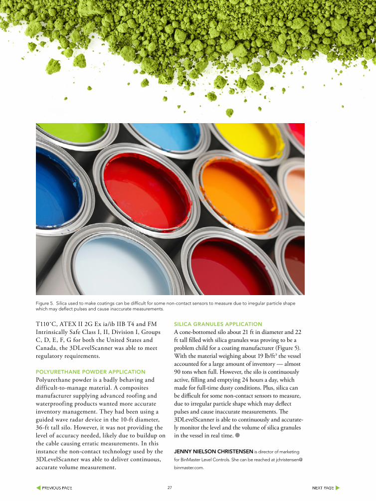
SIlICA GRANulES APPlICATIoN
A cone-bottomed silo about 21 ft in diameter and 22 ft tall filled with silica granules was proving to be a problem child for a coating manufacturer (Figure 5). With the material weighing about 19 lb/ft3 the vessel accounted for a large amount of inventory — almost 90 tons when full. However, the silo is continuously active, filling and emptying 24 hours a day, which made for full-time dusty conditions. Plus, silica can be difficult for some non-contact sensors to measure, due to irregular particle shape which may deflect pulses and cause inaccurate measurements. The 3DLevelScanner is able to continuously and accurate-ly monitor the level and the volume of silica granules in the vessel in real time.
JENNy NIElSoN CHRISTENSEN is director of marketing
for BinMaster Level Controls. She can be reached at jchristensen@
binmaster.com.
Figure 5. Silica used to make coatings can be difficult for some non-contact sensors to measure due to irregular particle shape which may deflect pulses and cause inaccurate measurements.

28
SIZE REDUCTION SOLUTIONSCHALLENGE CHALLENGE CHALLENGE
SOLUTION SOLUTIONSOLUTION
PigmentsResins
PVC Rework
Universal MillWith interchangeable grind-ing elements, the versatile Universal Mill allows maxi-mum grinding flexibility for fine and ultra-fine particle size reduction.
FertilizerSuper
Absorbant Polymers
Roll CrusherNarrow particle size distribu-tion is achieved by controlling a combination of variables including roll speed, roll gap, differential speed, feed rate and roll surface design.
Cryogenic Grinding Of
Rubber & Plastic
Gap MillThe Gap Mill features an adjustable grinding gap between the conical shaped rotor and a corrugated baf-fle for fine grinding down to the 25 µm size.
601 Corporate Woods PkwyVernon Hills, IL 60061901-363-0921www.bauermeisterusa.com
Find Out More > Find Out More > Find Out More >

29
Properly Size Motors for Screw FeedersConsider the effect of different material when specifying power requirements
By Dan Haugh, Hapman
A SCREW feeder is commonly used to meter flow in powder processing applications because of ease of use, low maintenance, and material integrity without degradation. The relatively simplistic equipment design of the screw feeder can be misleading when selecting and specifying motor and auger sizes.
Sizing feeders with the proper motor size and auger for optimal processing is not as straight for-ward as matching the capacity of the auger/feeder to the material. Horsepower requirements can vary significantly with different material. As the auger diameters increase, the differences in powder can result in a dramatic increase in horse power requirements. This is because the surface area of auger and material contact increase dramatically. Powders that have a high coefficient of friction can result in big changes in horsepower requirements. The length of the feeder nozzle and auger is another
significant factor in the horsepower requirements. When a feeder is elevating material, two other factors must be considered, the angle of the incline feeder and the overall height. The angle will deter-mine the overall length of the feeder.
An illustration of this concept requires a specified material example. The example materials selected in this study are used to demonstrate the differences in power requirements based on the extremes of mate-rial properties of seemingly similar elements. The mentioned example materials are not intended to be a comprehensive list.
The basis for analysis will be a series of assumed low-, medium-, and high-volume feeder sizes. The low volume is 60in3 to 5ft3/hr, with a 600-in3 hopper, (LV) the medium volume is assumed 1ft3 to 50 ft3/hr with a 1ft3-hopper, (MV), and the high volume 5ft3 to 1,000ft3/hr with a 3ft3-hopper, (HV).
Figure 1. This graph shows the overall capacity of all three size feeders with various size augers.

30
To calculate the horsepower given an auger size you can use these set of equations:
HPf = LN FdFb = (Horsepower to run an empty feeder)
1,000,000
HPm = CLρ FfFmFp = (Horsepower to run a feeder full*)
1,000,000
Total HP = (HPf + HPm)Fo
e
C = Capacity in ft3/hre = efficiency (Assumed to be 85% for chain driven
augers)Fb = Hanger bearing friction (Use 2.0 for Nylon bear-
ing)Fd = Auger diameter factorFf = Flight factor (Assumed 1.0 for standard augers)Fm = Material characteristics factor (friction factor)Fo = Overload factor (Use the equation Fo =
-0.567(HPf+HPm) + 3.113) Use 1.0 for HPf+HPm> 5.2
L = Total Length of auger, feetN = Operating speed, RPM (use 100 rpms)ρ = Density of material lb/ft3
HPf = Friction HorsepowerHPm = Horsepower required to move materialHP = Total Horsepower
*All assumptions and calculations in this study are based on a 100% full auger.
Figure 1 shows the overall capacity of all three size feeders with various size augers. The 8 in., 10 in. and 12 in. are not part of the standard auger for these three feeders, but are shown for completeness of data. Capacity dramatically increases from 3 in. to 12 in.
PoWER REQuIRED FoR DIFFERENT MATERIAlS
The graph in Figure 2 shows the calculated horse-power draw for three different size feeders using five
Figure 2. Power draw increases to 2.13 hp for sand with a 6 ½-in. auger.
Powder Fm ρ, lb/ft3
Activated Carbon 1.2 17
Lime 2.0 35-42
Flour 0.4 48
Baking Powder 0.6 56
Sand 1.7 99
Feeder Model Fd Auger Sizes, inches
Standard Lengths, inches
Auger Sizes, inches
LV Feeder 1.2 17” 22” 0.25”-1.25”
MV Feeder 2.0 35”-42” 30” 1.375”-2”
HV Feeder 0.4 48” 42” 2.25”-6.5”
PRoPERTy TABlE FoR PoWDERS
FEEDER SIzES AND PRoPERTIES

31
Dense Phase System Eliminates Extruder IssuesSolution not only improves quality, but safety as well
A WIRE manufacturer using polyethelene and polybutodinene pellets found that fines and angel hair were causing defects in the extrusion process. The customer needed to improve the consistency of the quality of their product at the end of the extruder. In addition, they were concerned about safety and reducing power consumption levels.
SySTEM TAKES SAFETy INTo CoNSIDERATIoN
The customer approached Horizon Systems of Lawrence, Kan., to find a solution. Horizon Systems invited them to its testing center to participate in full-scale testing of the solution. The customer was pleased to discover that the solution, a Horizon 4-in. pressure ConTran™ continuous dense phase system, eliminated the angel hair and fines, used less horsepower, and integrated easily into their existing process. It also gave them floor-level access to the bulk bag unloader bag spout boxes which eliminated the use of service platforms.
ConTran technology is an evolution of continuous dense phase convey-ing of dry bulk materials. This technology is based on maintaining the material-to-air flow ratio at a pre-selected (material dependent) constant, thus creating and sustaining dense phase, low velocity, gentle action ‘wave-form’ flow.
Originally, the customer requested a pressure pot dense phase system which requires significantly higher horsepower due to the use of compressed air. After completed testing of the new solution, the customer changed their scope to a compressed air continuous dense phase system and chose to imple-ment the more efficient Horizon system.
HoRIzoN SySTEMS INC.www.horizonsystemsinc.com
different powders. The horsepower is graphed versus the size auger. The auger is sized based on the rate required. The power draw is a result of the size of the auger and the friction factor for the material. The graph in Figure 2 shows the power draw increase to 2.13 hp for sand with a 6 ½-in. auger. For larger augers (larger than 6 ½ in.) the horsepower increases dramatically and could be in excess of 4 hp for sand with a 12-in. auger.
The lengths of the augers are based on industry standard feeder sizes and range from; 22 in–30 in. and to 42 in. The standard auger length and diameter depends on the size feeder and delivery rate. However,
Figure 3. When the length of the nozzle increases, the amount of horsepower required increases roughly proportionally.

32
when the length of the nozzle increases, the amount of horsepower required increases roughly proportion-ally (see Figure 3).
Even when two separate materials appear to be the same, small variations in properties can produce very different results in the auger sizing and the horsepower requirements. When performing feeder sizing, it’s criti-cal to know the exact type of powder and not just the name of the material. As seen in Figure 4, non-hydrated lime and hydrated lime are very different in the horse-power requirements. This is mainly a result of a much larger coefficient of friction (Fm = 2.0) for non-Hydrated Lime versus Hydrated Lime (Fm = 0.8). The graph shows a horsepower difference of 0.7 horsepower for a 6.5-in. auger and as high as 2.3 hp for an auger 12 in. in diameter. Clearly with larger augers, you may have an undersized motor if you used the hydrated lime.
SPECIAl VERTICAl FEEDER CASE
To this point, the study has only evaluated a horizontal
feeder. In many cases, material must be fed vertically into a silo, mix tank, reactor, dry mixer or some other storage or process equipment. Vertical feeding requires additional power. The total horsepower calculation can now be expanded by adding a third horsepower HPl (lift). So the completed equation would be:
Total HP = (HPf + HPm)Fo + HPl
e
The horsepower to raise a given amount of mate-rial is calculated as the work done lifting the material divided by the time, (power = work done/time). This can be expressed in the case of lifting 100 pounds of material in ten seconds up 10 feet. The work done is equal to 100lb × 10feet or 1,000 lb-ft. Since it was done in 10 seconds the power is equal to P = 1,000 lb-ft/10 seconds or 100 lb-ft/second. One horsepower is equal to 550 lb-ft/second. Therefore, the horsepower required is equal to 100/550 or 0.182 HP.
Continuing with this logic, a comparison can be made between flour and non-hydrated lime. The
Figure 4. Non-hydrated lime and hydrated lime are very different in horsepower requirements as a result of a much larger coefficient of friction.

33
2-in. and 4-in. augers shown in Figure 5 illustrate the horsepower requirement increases with both the length of the auger and the height at which the material is lifted. When a feeder is set at a 20° angle, the length of the auger increases and larger horsepower requirements result. For the same type of powder the 60° angle is best; however no slippage was calculated. In general, a shorter length of auger to reach the elevation is optimal. In practice, the amount of slippage will increase with increased angle, and operation is generally less efficient above 60°.
Do THE CAlCulATIoNS
This study evaluated the impact that auger diameter, material moved, length and lifting height have on the power required for a screw feeder. The many different types of screw feeders were not considered in this study, but the foundation of principles will apply to most variations. The feeder auger must be
completely full of material to allow for accurate and consistent delivery. For this reason, the study didn’t discuss less than 100% full auger.
If the auger is less than 100% full, some modifications to the above equations are necessary, but the basic principles apply. When designing equipment for metered feeding with an auger type feeder, one can be easily misled by overly compli-cated devices — thus, adding expense and unnec-essary intricacy to the overall design of a powder handling system. This study validated the need for accurate identification of material, lift, and pro-cessing time related to auger sizing and horsepower requirements. Taking the time to understand the correct calculations and data required will result in an optimal equipment selection and expected performance.
DAN HAuGH is product manager, feeders at Hapman. He can
be reached at [email protected].
Figure 5. Horsepower requirements increase with both the length of the auger and the height at which the material is lifted.

34
We provide the validation that every design, component, installation,
operation and performance meets your cGMP requirements.
K-Tron is known worldwide for engineering and delivering superior systems that make industrial processes efficient, reliable and profitable.
We know from experience that what you put into your process directly affects what you get out of it. With world-class mechanical design,
precision weighing technology, and cutting-edge control systems,
K-Tron means productivity throughout your process –
and throughout your business.
Solid Dosage Production
Sanitary Transfer
Tablet & Capsule Conveying
Tablet Press Lubrication
Sharon NowakGlobal Business Development Manager - K-TronPharmaceutical & Food Industries
Learn how K-Tron can solve your material handling and feeding challenges. Visit us at ktron.com
THE PROCESS OF
ASSuRaNCe
Continuous Processes Vitamin Production Sanitary Dispensing