effective may 2016 td157004en low-voltage switched...
TRANSCRIPT

Technical Data TD157004ENEffective May 2016 Supersedes June 2014
Low-voltage switched capacitor banks and switched detuned filters
AUTOVAR filterAUTOVAR 300 AUTOVAR 300AUTOVAR 600
ContentsDescription Page
AUTOVAR 300 automatic power factor correction capacitor systems . . . . . . . . . . . . . . . . 2AUTOVAR 600 and AUTOVAR detuned filter automatic power factor correction capacitor systems . . . . . . . . . . . . . . . . . . . . . . . . . 7Current transformers . . . . . . . . . . . . . . . . . . . . . . 18
otee:N Images contained in this document may be shown with optional components and features not included as part of the base offering .

2
Technical Data TD157004ENEffective May 2016
Low-voltage switched capacitor banks and switched detuned filters
EATON www.eaton.com
AUTOVAR 300 automatic power factor correction capacitor systems
AUTOVAR 300
Product description
Automatically switched power factor correction systems for low-voltage applications .• Wallmount design is ideal for minimum space requirements• Programmable to automatically add/subtract capacitor stages
to maintain preset target power factor• Heavy-duty, three-phase capacitor construction• Two-year warranty of cells against manufacturing defects• Entire cabinet assembly is ULT 508A and
CSAT C22 .2 No . 190 Listed• Capacitors are UL 810 recognized
Applications
AUTOVAR 300 is an ideal capacitor bank to automatically regulate power factor where floor space is limited and expansion of the facility’s electrical load is not expected .
Features and specifications
Configuration
• Cabinete: Wallmounting 12 gauge steel with ANSI 61 gray, NEMAT 1 (gasketed)
• Power line interconnecte: Rugged, power distribution block connection . Typical power distribution block can accommodate phase wire sizes from 4 AWG to 500 kcmil; typical ground lug can accommodate wire sizes from 14 AWG to 2/0 AWG . Consult equipment approval drawings for actual lug size
• Control wiringe: UL type MTW/AWM, CSA TEW 105 °C copper wire is standard
• Fusinge: 200,000 A interrupting capacity provided on all three phases of each stage . Blade-type fuses mounted on insulator stand-offs with cleared-fuse indicating lights
• Cleared-fuse lightse: Cleared-fuse neon indicating lights for each phase and stage located on the door
• Door interlocke: Door interlock automatically disengages capacitors . Power continues to be provided to the unit until the disconnect is open
• Exhaust fane: Provides ventilation; dust filtering included• Safetye: Ground fault interruption provides protection in case
of accidental contact with control power and ground• Conduit/cable entrye: Available in top/side cable entry• Thermal sensinge: Built-in thermal sensing, alarming, and
protection feature allows the unit to operate in optimal temperature while alerting the user of ambient temperature exceeding the nominal operating range . Stages will be automatically switched off if temperature exceeds the maximum specified temperature
• Temperature rangee: The operating temperature range is –20 °C to +46 °C, and the storage temperature range is –40 °C to +55 °C . For optimal equipment life, the temperature should not exceed 35 °C annual average, and the environment should not exceed Pollution Degree 2 as defined in UL 61010-1
3
Technical Data TD157004ENEffective May 2016
Low-voltage switched capacitor banks and switched detuned filters
EATON www.eaton.com
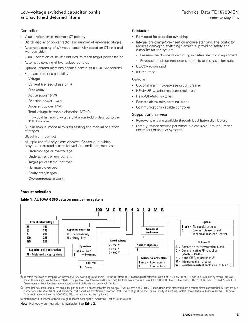
Controller
• Visual indication of incorrect CT polarity• Digital display of power factor and number of energized stages• Automatic setting of c/k value (sensitivity based on CT ratio and
kvar available)• Visual indication of insufficient kvar to reach target power factor• Automatic sensing of kvar values per step• Optional communications capable controller (RS-485/ModbusT)• Standard metering capability:
• Voltage
• Current (sensed phase only)
• Frequency
• Active power (kW)
• Reactive power (kvar)
• Apparent power (kVA)
• Total voltage harmonic distortion (VTHD)
• Individual harmonic voltage distortion (odd orders up to the 19th harmonic)
• Built-in manual mode allows for testing and manual operation of stages
• Global alarm contact• Multiple user-friendly alarm displays . Controller provides
easy-to-understand alarms for various conditions, such as:• Undervoltage or overvoltage
• Undercurrent or overcurrent
• Target power factor not met
• Harmonic overload
• Faulty step/stages
• Overtemperature alarm
Contactor
• Fully rated for capacitor switching• Integral pre-charge/pre-insertion module standard . The contactor
reduces damaging switching transients, providing safety and durability for the system• Lessens the chance of disrupting sensitive electronic equipment
• Reduced inrush current extends the life of the capacitor cells
• UL/CSA recognized• IEC 6b rated
Options
• Optional main molded-case circuit breaker• NEMA 3R weather-resistant enclosure• Hand-Off-Auto switches• Remote alarm relay terminal block• Communications capable controller
Support and service
• Renewal parts are available through local Eaton distributors• Factory trained service personnel are available through Eaton’s
Electrical Services & Systems
Product selection
Table 1. AUTOVAR 300 catalog numbering system
a
100 M C S R 4 3 1 3 M S
kvar at rated voltage
255075100125
150175200225250
Capacitor cell construction
M = Metalized polypropylene
Capacitor cell class
C = Standard-dutyH = Heavy-duty
Operation
Blank = FixedS = Switched
Options b
A = Remote alarm relay terminal blockC = Communicating PF controller (Modbus RS-485)H = Hand-Off-Auto switches cM = Integrated main breakerW = Weather-resistant enclosure (NEMA 3R)
Number of contactors
Blank = 5 contactors 3 = 3 contactors a
Number of enclosures
1
Number of phases
3
Rated voltage
2 = 240 V4 = 480 V6 = 600 V
Cell Type
R = Round
Special
Blank = No special options S = Special (please consult Technical Resource Center)
To obtain five levels of stepping, we incorporate 1:2:2 switching. For example, 75 kvar unit states 5x15 switching with obtainable output of 15, 30, 45, 60, and 75 kvar. This is created by having 1x15 kvar and 2x30 kvar stages on the three contactors. Output levels are then reached by switching the three contactors as 15 kvar 1:0:0, 30 kvar 0:1:0 or 0:0:1, 45 kvar 1:1:0 or 1:0:1, 60 kvar 0:1:1, and 75 kvar 1:1:1. Part numbers without five physical contactors switch individually in a round-robin fashion.
bPlease include option codes at the end of the part number in alphabetical order. For example, if you ordered a 75MCSR6313 and added a main breaker (M) and a remote alarm relay terminal (A), then the part number would be: 75MCSR6313AM. Remember that if you have any “Special” (S option), that letter must go at the end. For availability of S options, contact Eaton’s Technical Resource Center (TRC) power factor application engineers at 1-800-809-2772, choose option #4, then option #2.
cManual control is always available through controller menu system, even if the H option is not selected.
otee:N Not every configuration is available . See Table 2 .

4
Technical Data TD157004ENEffective May 2016
Low-voltage switched capacitor banks and switched detuned filters
EATON www.eaton.com
Table 2. Wallmounted AUTOVAR 300 switched capacitor banks—low-voltage applications, 60 Hz units
kvarStep xkvar
Rated current amperes
Base shipping weight in lb (kg) a
Catalog number
240 V
25 5 x 5 60 217 (98.5) 25MCSR231350 5 x 10 120 255 (115.8) 50MCSR231375 5 x 15 180 260 (118.0) 75MCSR2313100 5 x 20 240 270 (122.6) 100MCSR231125 5 x 25 300 292 (132.6) 125MCSR231480 V
50 5 x 10 60 200 (90.8) 50MCSR431375 5 x 15 90 210 (95.3) 75MCSR4313100 5 x 20 120 210 (95.3) 100MCSR4313125 5 x 25 150 240 (109.0) 125MCSR4313150 5 x 30 180 240 (109.0) 150MCSR4313175 5 x 35 210 260 (118.0) 175MCSR431200 5 x 40 241 270 (122.6) 200MCSR431225 5 x 45 270 290 (131.7) 225MCSR431250 5 x 50 300 292 (132.6) 250MCSR431600 V
50 5 x 10 48 200 (90.8) 50MCSR631375 5 x 15 72 210 (95.3) 75MCSR6313100 5 x 20 96 210 (95.3) 100MCSR6313125 5 x 25 120 240 (109.0) 125MCSR6313150 5 x 30 144 240 (109.0) 150MCSR6313175 5 x 35 168 260 (118.0) 175MCSR631200 5 x 40 192 270 (122.6) 200MCSR631225 5 x 45 216 290 (131.7) 225MCSR631250 5 x 50 240 292 (132.6) 250MCSR631
aTo calculate AUTOVAR 300 weight: 1. Obtain base unit weight from Table 2. 2. Add option weights as necessary: A = 1 lb M = 50 lb enclosure weight adder plus circuit C = 1 lb breaker weight (see circuit breaker table) H = 5 lb S = Consult Eaton’s Technical Resource Center (TRC) at 1-800-809-2772, W = 10 lb choose option #4, then option #2
otee:N Other ratings available . Please consult factory . kvar output is voltage and frequency dependent . 60 Hz units are shown . For other voltages and frequencies, consult Eaton Technical Resource Center (TRC) at 1-800-809-2772, choose option #4, then option #2 .
Table 3. Spare fuses
kvar rating/bank
Eaton fusepart number
240 Volts
480 Volts
600 Volts Amperes
5 10 10 30 SP030217-0029J — 15 20 50 SP030217-0037D 10 20 — 60 SP030217-0037E — 25 25–30 80 SP030217-0037G 15 30 40 100 SP030217-0037J 20 40 50 125 SP030217-0037K 25 50 — 150 SP030217-0037L
Table 4. Renewal partsDescription Catalog number
Replacement PF controller, ACX type SP039010-0035UReplacement contactor, 72 A SP039010-0014BReplacement contactor, 32 A SP039010-0014C
Table 5. Options
DescriptionOption code
Remote alarm relay terminal block—relay terminal block for a remote alarm to indicate controller alarm status
A
Communicating controller (Modbus RS-485) CHand-Off-Auto switch—provides manual control to connect or disconnect capacitor stages regardless of controller output a
H
Molded-case circuit breaker (see circuit breaker section) MWeather-resistant enclosure (NEMA 3R gasketed) W
aManual control is always available through controller menu system, even if the H option is not selected.
Table 6. Integrated main breakers—AUTOVAR 300
kvar
AUTOVAR rated current amperes
Breaker size (amperes) a
Breaker interrupting rating (kA)
Breaker weight in lb (kg)
Standard wire lug size b
240 V
25 60 125 100 10 (4.5) (1) #3–35050 120 250 100 10 (4.5) (1) #3–35075 180 250 100 10 (4.5) (1) #3–350100 240 400 100 10 (4.5) (2) #3/0–250125 300 600 100 25 (11.4) (2) #3/0–350480 V
50 60 125 65 10 (4.5) (1) #3–35075 90 125 65 10 (4.5) (1) #3–350100 120 250 65 10 (4.5) (1) #3–350125 150 250 65 10 (4.5) (1) #3–350150 180 250 65 10 (4.5) (1) #3–350175 210 400 65 10 (4.5) (2) #3/0–250200 240 400 65 10 (4.5) (2) #3/0–250225 270 400 65 10 (4.5) (2) #3/0–250250 300 600 65 25 (11.4) (2) #3/0–350600 V
50 48 125 35 10 (4.5) (1) #3–35075 72 125 35 10 (4.5) (1) #3–350100 96 250 35 10 (4.5) (1) #3–350125 120 250 35 10 (4.5) (1) #3–350150 144 250 35 10 (4.5) (1) #3–350175 168 250 35 10 (4.5) (1) #3–350200 192 400 35 10 (4.5) (2) #3/0–350225 216 400 35 10 (4.5) (2) #3/0–350250 240 400 35 10 (4.5) (2) #3/0–350
aBreakers are sized at a minimum of 135% of the unit rated Amperes per the NEC.TbSee equipment drawings for actual lug sizes.
5
Technical Data TD157004ENEffective May 2016
Low-voltage switched capacitor banks and switched detuned filters
EATON www.eaton.com
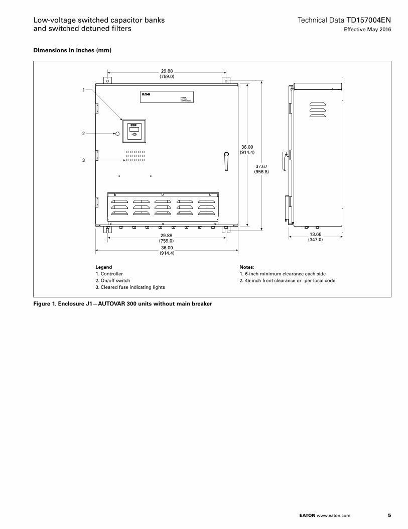
Dimensions in inches (mm)
BLR-ACXPower Factor Controller
esc
POWER FACTOR CORRECTION
69B1007G01
®
13.66(347.0)
29.88(759.0)
37.67(956.8)
29.88(759.0)36.00
(914.4)
1
2
3
36.00(914.4)
Notes:1. 6-inch minimum clearance each side2. 45-inch front clearance or per local code
Legend1. Controller2. On/off switch3. Cleared fuse indicating lights
Figure 1. Enclosure J1—AUTOVAR 300 units without main breaker

6
Technical Data TD157004ENEffective May 2016
Low-voltage switched capacitor banks and switched detuned filters
EATON www.eaton.com
BLR-ACXPower Factor Controller
esc
R
POWER FACTOR CORRECTION
69B1007G01
13.66(347.0)
61.67(1566.4)
29.88(759.0)36.00
(914.4)
1
2
4
3
60.00(1524.1)
Notes:1. 6-inch minimum clearance each side2. 45-inch front clearance or per local code
Legend1. Controller2. On/off switch3. Cleared fuse indicating lights4. Circuit breaker operating handle
Figure 2. Enclosure J2—AUTOVAR 300 units with main breaker

7
Technical Data TD157004ENEffective May 2016
Low-voltage switched capacitor banks and switched detuned filters
EATON www.eaton.com
AUTOVAR 600 and AUTOVAR detuned filter correction capacitor systems
AUTOVAR 600
AUTOVAR detuned filter
AUTOVAR detuned filter—interior view
Product description
• Programmable to automatically add/subtract capacitor stages to maintain preset target power factor
• Three-phase capacitor cell construction• Five-year warranty of cells against manufacturing defects
(units with heavy-duty cells) . Two-year warranty of cells against manufacturing defects (units with standard-duty cells)
• Entire cabinet assembly is UL 508A and CSA C22 .2 No . 190 Listed
• Capacitors are UL 810 recognized• Cool operating, 100% copper wound, thermal-protected
reactors are sized up to 150% of rated capacitor current (AUTOVAR detuned filter only)
Applications
• Service entrance or substation power factor correction installations requiring precise maintenance of target power factor (AUTOVAR 600)
• Service entrance or substation power factor correction installations requiring precise maintenance of target power factor in three-phase, nonlinear, high harmonic environments (AUTOVAR detuned filter)
• Typically connected at main low-voltage switchgear
Features and specifications
Configuration
• Cabinete: 12 gauge steel with ANSI 61 gray, baked finish . Removable lift bolts standard, NEMA 1 (gasketed)
• Power line interconnecte: Rugged, copper busbar connection with access provided for top entry . Contact factory for availability of bottom entry . Busbars are braced for 65 kA (optional 100 kA rating available) . All internal power wiring connections from bus are laid out on a most direct basis with minimum bends for ease of troubleshooting . Clear barrier limiting access to live parts included standard
• Modular tray designe: Capacitor stages arranged in modular trays with capacitors, fuses, cleared-fuse indicating lights, and contactors grouped in a logical, easily understood layout . This permits easy access, quick identification of operating problems, and ease of expandability
• Fusinge: UL recognized, 200,000 A interrupting capacity provided on all three phases of each stage . Blade-type fuses mounted on insulator stand-offs
• Cleared-fuse indicating lightse: LEDs located door-mounted and neon at individual fuses to facilitate tracing of cleared fuses
• Push-to-teste: Allows testing of door-mounted LED cleared fuse indicating lights
• AutoLocatee: When door is open and bus is energized, fuse circuit automatically checks for cleared fuses . If a fuse has cleared, the light at the fuse turns on for easy troubleshooting
• Door interlocke: Door interlock automatically turns off control circuit when engaged . Power continues to be provided to the unit until disconnect is open
• Exhaust fanse: Two side louver fans per cabinet provide cooling and reduce operator exposure to discharge . Replaceable dust filtering provided . Dust filters can be replaced without opening cabinet
• Ease of expansione: Capacitor stage nests are self-contained and can be added in the field . Two bolts mount the nest in the field . Control wire plugs connect to factory standard wire harness on the left side of the cabinet
• Ease of replacemente: Cells can be easily replaced individually by removing the mounting bolt and lifting out of the nest without removal of any other components
• Thermal sensinge: Built-in thermal sensing, alarming, and protection feature allows the unit to operate in optimal temperature while alerting the user of ambient temperature exceeding the nominal operating range . Stages will be automatically switched off if temperature exceeds the maximum specified temperature
• Temperature rangee: The operating temperature range is –20 °C to +46 °C, and the storage temperature range is –40 °C to +55 °C . For optimal equipment life, the temperature should not exceed 35 °C annual average, and the environment should not exceed Pollution Degree 2 as defined in UL 61010-1

8
Technical Data TD157004ENEffective May 2016
Low-voltage switched capacitor banks and switched detuned filters
EATON www.eaton.com
Controller
• Visual indication of incorrect CT polarity• Digital display of power factor and number of energized stages• Automatic setting of c/k value (sensitivity based on CT ratio and
kvar available)• Visual indication of insufficient kvar to reach target power factor• Automatic sensing of kvar values per step• Optional communications capable controller (RS-485/Modbus)• Standard metering capability:
• Voltage
• Current (sensed phase only)
• Frequency
• Active power (kW)
• Reactive power (kvar)
• Apparent power (kVA)
• Total voltage harmonic distortion (VTHD)
• Individual harmonic voltage distortion (odd orders up to the 19th harmonic)
• Built-in manual mode allows for testing and manual operation of stages
• Global alarm contact• Multiple user-friendly alarm displays . Controller provides
easy-to-understand alarms for various conditions, such as:• Undervoltage or overvoltage
• Undercurrent or overcurrent
• Target power factor not met
• Harmonic overload
• Faulty step/stages
• Overtemperature alarm
Contactor
• Fully rated for capacitor switching• Integral pre-charge/pre-insertion module standard . The contactor
reduces damaging switching transients, providing safety and durability for the system• Lessens the chance of disrupting sensitive electronic equipment
• Reduced inrush current extends the life of the capacitor cells
• UL/CSA recognized• IEC 6b rated
Reactors
• Detuninge: Standard reactor designs are detuned to the 4 .2nd harmonic and recommended to protect capacitors against harmonic resonance . Detuning to the 4 .7th harmonic is available as an option . The harmonic spectrum should be evaluated for applications involving reactors detuned to the 4 .7th harmonic to ensure optimal equipment life, specifically when used in conjunction with six-pulse motor drives
• Windingse: 80 °C temperature rise design 100% copper windings for minimal losses
• Thermal overload protectione: Each reactor includes three normally closed, auto reset thermostats that open at 180 °C . When thermostats engage, the contactor opens
• Insulatione: 220 °C insulation system• Warrantye: One-year replacement of reactors
Additional features
• Optional molded-case main circuit breaker• Ground fault interruption provides protection in case of accidental
contact with control power and ground• Control wiring—standard NEC color-coded modular bundles
with quick disconnect feature for ease of troubleshooting or ease of expendability . UL type MTW/AWM, CSA TEW 105 °C copper wire is standard .
• Optional digital metering—IQ 250• Mechanical wire lugs are included as standard equipment .
Typical phase lugs range from (2) 6 AWG–350 kcmil to (4) 3 AWG–750 kcmil . Typical ground lug can accept wire from 6 AWG to 350 kcmil . Lugs are compatible with copper wire 90 °C, used at the 75 °C rating . See Table 16 for standard lug sizes, and consult equipment drawings for actual lug sizes
• Heavy-duty capacitor cells are standard on AUTOVAR detuned filter and optional on AUTOVAR 600 . For 480 V units, standard-duty cells are 525 V rated, and heavy-duty cells are 600 V rated
Support and service
• Renewal parts are available through local Eaton distributors• Factory trained service personnel are available through Eaton’s
Electrical Services & Systems
AUTOVAR detuned filter—capacitor cabinet
AUTOVAR detuned filter—reactor cabinet
Modular step nest assembly
Dust filter tray

9
Technical Data TD157004ENEffective May 2016
Low-voltage switched capacitor banks and switched detuned filters
EATON www.eaton.com
Product selection
Table 7. Catalog numbering system
a
800 T H F S R 4 3 2 Y S
kvar at rated voltage
75100150200250300350
400450500550600550700
720800840900100011001200
Construction
T = Tray design
Capacitor cell class
C = Standard-dutyF = Heavy-duty (filtered units)H = Heavy-duty (unfiltered units)
Operation
Blank = FixedS = Switched Options a
A = Remote alarm relay terminal blockB = Fully insulated main busC = Communicating PF controller (Modbus RS-485)H = Hand-off auto switches bM = Integrated main breakerM1 = Integrated main breaker with high interrupting rating (includes N1 option)N1 = 100 kA busbar bracingQ = IQ 250 electronic meterT1 = Integrated CVX series surge protectionT2 = Integrated SPD series surge protectionW = Weather-resistant enclosure (NEMA 3R)Y = Standard filter detuned to the 4.2nd harmonic
Number of enclosures
12
Number of phases
3
Rated voltage
2 = 240 V4 = 480 V6 = 600 V
Cell type
R = Round
Unit type
H = FilteredP = Unfiltered)
Special
Blank = No special options S = Special (please consult Technical Resource Center)
Please include option codes at the end of the part number in alphabetical order. For example, if you ordered a 350THFSR432Y and added a main breaker (M) and a remote alarm relay terminal (A), then the part number would be: 350THFSR432AMY. Remember that if you have any “Special” (S option), that letter must go at the end. For availability of S options, contact Eaton’s Technical Resource Center (TRC) power factor application engineers at 1-800-809-2772, choose option #4, then option #2.
bManual control is always available through container menu system, even if the H option is not selected.
Table 8. Options—AUTOVAR 600 and AUTOVAR detuned filter
DescriptionOption code
Remote alarm relay terminal block—relay terminal block for a remote alarm to indicate controller alarm status
A
Fully insulated main bus BCommunicating PF controller (Modbus RS-485) CHand-off-auto switch provides manual control to connect or disconnect capacitor stages regardless of controller output a
H
Integrated main breaker MIntegrated main breaker with high interrupting rating (see breaker table for more information), includes 100 kA busbar bracing
M1
100 kA busbar bracing N1Integrated CVX series surge protection, without sine wave tracking T1Integrated SPD series surge protection, 160 kA per phase, with sine wave tracking
T2
IQ 250 electronic meter b QWeather-resistant enclosure (NEMA 3R gasketed) c W Standard filter detuned to the 4.2nd harmonic d Y
aManual control is always available through menu controller on system, even if the H option is not selected.
bNot available on NEMA 3R units (W option).cOnly available on AUTOVAR 600 with heavy-duty cells and AUTOVAR detuned filters
using ‘L + L’, ‘L + KK’, and ‘KK + KK’ enclosures.dTuning to the 4.2nd harmonic is the preferred option. Other tunings available. Contact Eaton’s
Technical Resource Center (TRC) power factor application engineers at 1-800-809-2772, choose option #4, then option #2.
To calculate AUTOVAR 600 or AUTOVAR detuned filter weight:
1. Obtain base unit weight from Table 11, Table 9, or Table 13 (as appropriate) .
2. Add option weights as necessary: A = 1 lb (0 .5 kg) B = 10 lb (4 .5 kg) C = 1 lb (0 .5 kg) H = 10 lb (4 .5 kg) M = Circuit breaker weight (see circuit breaker table) M1 = 10 lb (4 .5 kg) hardware weight adder plus circuit breaker weight (see circuit breaker table) N1 = 10 lb (4 .5 kg) T1 = 5 lb (2 .3 kg) T2 = 10 lb (4 .5 kg) Q = 5 lb (2 .3 kg) W = 10 lb (4 .5 kg) per door Y = 0 lb (0 kg)

10
Technical Data TD157004ENEffective May 2016
Low-voltage switched capacitor banks and switched detuned filters
EATON www.eaton.com
Table 9. AUTOVAR 600 floor-mounted switched capacitor banks units with standard-duty cells—low-voltage applications, 60 Hz units
kvarStep xkvar
Rated currentamperes
Base shipping weight in lb (kg)
Base catalog number
240 Vac
75 3 x 25 180 644 (292.4) 75TPCSR231100 4 x 25 240 692 (314.2) 100TPCSR231125 5 x 25 300 740 (336.0) 125TPCSR231150 6 x 25 361 788 (357.8) 150TPCSR231200 8 x 25 481 884 (401.3) 200TPCSR231250 10 x 25 600 944 (428.6) 250TPCSR231300 12 x 25 720 1022 (464.0) 300TPCSR231350 7 x 50 844 1616 (734.0) 350TPCSR231400 8 x 50 965 1704 (774.0) 400TPCSR231480 Vac
100 2 x 50 120 588 (266.7) 100TPCSR431150 3 x 50 180 632 (287.0) 150TPCSR431200 4 x 50 240 676 (306.9) 200TPCSR431250 5 x 50 300 720 (326.9) 250TPCSR431300 6 x 50 360 764 (346.9) 300TPCSR431350 7 x 50 420 808 (366.8) 350TPCSR431400 8 x 50 480 852 (386.8) 400TPCSR431450 9 x 50 540 896 (406.8) 450TPCSR431500 10 x 50 600 944 (428.6) 500TPCSR431550 11 x 50 660 984 (446.7) 550TPCSR431600 12 x 50 720 1022 (464.0) 600TPCSR431660 11 x 60 792 1010 (458.5) 660TPCSR431700 7 x 100 840 1616 (734.0) 700TPCSR431720 12 x 60 864 1050 (476.7) 720TPCSR431800 8 x 100 960 1704 (774.0) 800TPCSR431900 9 x 100 1080 1792 (814.0) 900TPCSR4311000 10 x 100 1200 1888 (857.0) 1000TPCSR4311100 11 x 100 1320 1966 (893.0) 1100TPCSR4311200 12 x 100 1440 2044 (928.0) 1200TPCSR431600 Vac
100 2 x 50 46 588 (266.7) 100TPCSR631150 3 x 50 144 632 (287.0) 150TPCSR631200 4 x 50 192 676 (306.9) 200TPCSR631250 5 x 50 240 720 (326.9) 250TPCSR631300 6 x 50 288 764 (346.9) 300TPCSR631350 7 x 50 336 808 (366.8) 350TPCSR631400 8 x 50 384 852 (386.8) 400TPCSR631450 9 x 50 432 896 (406.8) 450TPCSR631500 10 x 50 480 944 (428.6) 500TPCSR631550 11 x 60 528 984 (446.7) 550TPCSR631600 12 x 50 576 1022 (464.0) 600TPCSR631660 11 x 60 634 1010 (458.5) 660TPCSR631700 7 x 100 672 1616 (734.0) 700TPCSR631720 12 x 60 692 1050 (476.7) 720TPCSR631800 8 x 100 768 1704 (774.0) 800TPCSR631900 9 x 100 864 1792 (814.0) 900TPCSR6311000 10 x 100 960 1888 (857.0) 1000TPCSR6311100 11 x 100 1056 1966 (893.0) 1100TPCSR6311200 12 x 100 1152 2044 (928.0) 1200TPCSR631
otee:N Other ratings available . Please consult factory . kvar output is voltage and frequency dependent . 60 Hz units are shown . For other voltages and frequencies, consult Eaton Technical Resource Center (TRC) at 1-800-809-2772, choose option #4, then option #2 .
Table 10. AUTOVAR 600 sizing chart for units with standard-duty cells, 60 Hz units
kvarStep x kvar
Enclosure size a
NEMA 1, without main breaker, no suffix
NEMA 1, with main breaker, M suffix
240 Volt
75 3 x 25 L L100 4 x 25 L L125 5 x 25 L L150 6 x 25 L L200 8 x 25 L L250 10 x 25 L L300 12 x 25 L L350 7 x 50 KK KK400 8 x 50 KK C/F480 Volt
100 2 x 50 L L150 3 x 50 L L200 4 x 50 L L250 5 x 50 L L300 6 x 50 L L350 7 x 50 L L400 8 x 50 L L450 9 x 50 L L500 10 x 50 L L550 11 x 50 L L600 12 x 50 L L660 11 x 60 L L700 14 x 50 KK KK720 12 x 60 L L800 8 x 100 KK C/F900 9 x 100 KK C/F1000 10 x 100 KK C/F1100 11 x 100 KK C/F1200 12 x 100 KK C/F600 Volt
100 2 x 50 L L150 3 x 50 L L200 4 x 50 L L250 5 x 50 L L300 6 x 50 L L350 7 x 50 L L400 8 x 50 L L450 9 x 50 L L500 10 x 50 L L550 11 x 50 L L600 12 x 50 L L660 11 x 60 L L700 14 x 50 KK KK720 12 x 60 L L800 8 x 100 KK KK900 9 x 100 KK KK1000 10 x 100 KK C/F1100 11 x 100 KK C/F1200 12 x 100 KK C/F
aEnclosure sizing for units with integrated surge protection or bottom entry can vary and may not be available on all kvar sizes. Contact Eaton’s Technical Resource Center at 1-800-809-2772, choose option #4, then option #2.
C/F = Consult factory

11
Technical Data TD157004ENEffective May 2016
Low-voltage switched capacitor banks and switched detuned filters
EATON www.eaton.com
Table 11. AUTOVAR 600 floor-mounted switched capacitor banks units with heavy-duty cells—low-voltage applications, 60 Hz units
kvarStep xkvar
Rated currentamperes
Base shipping weight in lb (kg)
Base catalog number
240 Vac
75 3 x 25 180 659 (298.9) 75TPHSR231100 4 x 25 240 712 (323.0) 100TPHSR231 125 5 x 25 300 765 (347.0) 125TPHSR231 150 6 x 25 361 818 (371.0) 150TPHSR231 200 8 x 25 481 924 (419.1) 200TPHSR231 250 10 x 25 601 994 (450.9) 250TPHSR231 300 12 x 25 720 1082 (490.8) 300TPHSR231 350 7 x 50 844 1686 (764.8) 350TPHSR231 400 8 x 50 965 1784 (809.2) 400TPHSR231 480 Vac
100 2 x 50 120 617 (279.9) 100TPHSR431150 3 x 50 180 677 (307.1) 150TPHSR431200 4 x 50 240 736 (333.8) 200TPHSR431 250 5 x 50 300 795 (360.6) 250TPHSR431 300 6 x 50 360 854 (387.4) 300TPHSR431 350 7 x 50 420 913 (414.1) 350TPHSR431 400 8 x 50 480 972 (440.9) 400TPHSR431 450 9 x 50 540 1031 (467.7) 450TPHSR431 500 10 x 50 600 1094 (496.2) 500TPHSR431 550 11 x 50 660 1149 (521.2) 550TPHSR431 600 12 x 50 720 1202 (545.2) 600TPHSR431 700 14 x 50 840 1826 (828.3) 700TPHSR431 800 8 x 100 960 1944 (881.8) 800TPHSR431 900 9 x 100 1083 2062 (935.3) 900TPHSR431 1000 10 x 100 1203 2198 (997.0) 1000TPHSR431 1100 11 x 100 1323 2296 (1041.4) 1100TPHSR431 1200 12 x 100 1443 2404 (1090.4) 1200TPHSR431 600 Vac
100 2 x 50 96 617 (279.9) 100TPHSR631150 3 x 50 144 677 (307.1) 150TPHSR631200 4 x 50 192 736 (333.8) 200TPHSR631 250 5 x 50 240 795 (360.6) 250TPHSR631 300 6 x 50 288 854 (387.4) 300TPHSR631 350 7 x 50 336 913 (414.1) 350TPHSR631 400 8 x 50 384 972 (440.9) 400TPHSR631 450 9 x 50 432 1031 (467.7) 450TPHSR631 500 10 x 50 480 1094 (496.2) 500TPHSR631 550 11 x 50 529 1149 (521.2) 550TPHSR631 600 12 x 50 576 1202 (545.2) 600TPHSR631 700 7 x 100 672 1826 (828.3) 700TPHSR631 800 8 x 100 768 1944 (881.8) 800TPHSR631 900 9 x 100 864 2062 (935.3) 900TPHSR631 1000 10 x 100 962 2198 (997.0) 1000TPHSR631 1100 11 x 100 1058 2296 (1041.4) 1100TPHSR631 1200 12 x 100 1155 2404 (1090.4) 1200TPHSR631
otee:N Other ratings available . Please consult factory . kvar output is voltage and frequency dependent . 60 Hz units are shown . For other voltages and frequencies, consult Eaton Technical Resource Center (TRC) at 1-800-809-2772, choose option #4, then option #2 .
Table 12. AUTOVAR 600 sizing chart for units with heavy-duty cells, 60 Hz units
kvarStep x kvar
Enclosure size a
NEMA 1, without main breaker, no suffix
NEMA 1, with main breaker, M suffix
NEMA 3R, without main breaker, W suffix
NEMA 3R, with main breaker, MW suffix
240 Volt
75 3 x 25 L L L L100 4 x 25 L L L L125 5 x 25 L L L L150 6 x 25 L L L L200 8 x 25 L L L L250 10 x 25 L L L L300 12 x 25 L L L L350 7 x 50 KK KK KK KK400 8 x 50 KK C/F KK C/F480 Volt
100 2 x 50 L L L L150 3 x 50 L L L L200 4 x 50 L L L L250 5 x 50 L L L L300 6 x 50 L L L L350 7 x 50 L L L L400 8 x 50 L L L L450 9 x 50 L L L L500 10 x 50 L L L L550 11 x 50 L L L L600 12 x 50 L L L L700 14 x 50 KK KK KK KK800 8 x 100 KK C/F KK C/F900 9 x 100 KK C/F KK C/F1000 10 x 100 KK C/F KK C/F1100 11 x 100 KK C/F KK C/F1200 12 x 100 KK C/F KK C/F600 Volt
100 2 x 50 L L L L150 3 x 50 L L L L200 4 x 50 L L L L250 5 x 50 L L L L300 6 x 50 L L L L350 7 x 50 L L L L400 8 x 50 L L L L450 9 x 50 L L L L500 10 x 50 L L L L550 11 x 50 L L L L600 12 x 50 L L L L700 14 x 50 KK KK KK KK800 8 x 100 KK KK KK KK900 9 x 100 KK KK KK KK1000 10 x 100 KK C/F KK C/F1100 11 x 100 KK C/F KK C/F1200 12 x 100 KK C/F KK C/F
aEnclosure sizing for units with integrated surge protection or bottom entry can vary and may not be available on all kvar sizes. Contact Eaton’s Technical Resource Center at 1-800-809-2772, choose option #4, then option #2.
C/F = Consult factory

12
Technical Data TD157004ENEffective May 2016
Low-voltage switched capacitor banks and switched detuned filters
EATON www.eaton.com
Table 13. Floor-mounted switched detuned filters— low-voltage, 60 Hz units
kvarStep x kvar
Rated current amperes
Base shipping weight in lb (kg)
Base catalog number
240 Vac
150 6 x 25 361 1830 (830.8) 150THFSR232Y 200 8 x 25 481 2222 (1008.8 200THFSR232Y 250 10 x 25 601 2525 (1146.4) 250THFSR232Y 300 12 x 25 720 2830 (1284.8) 300THFSR232Y 350 7 x 50 844 3090 (1401.6) 350THFSR231Y 400 8 x 50 965 3560 (1614.8) 400THFSR232Y 480 Vac
100 2 x 50 120 1105 (501.2) 100THFSR431Y150 3 x 50 180 1242 (564.6) 150THFSR431Y200 4 x 50 240 1438 (652.9) 200THFSR431Y250 5 x 50 300 1634 (741.8) 250THFSR431Y300 6 x 50 360 1830 (830.8) 300THFSR432Y350 7 x 50 420 2026 (919.8) 350THFSR432Y400 8 x 50 480 2222 (1008.8) 400THFSR432Y450 9 x 50 540 2371 (1076.4) 450THFSR432Y500 10 x 50 600 2525 (1146.4) 500THFSR432Y550 11 x 50 660 2750 (1248.5) 550THFSR432Y600 12 x 50 720 2830 (1284.8) 600THFSR432Y700 7 x 100 792 3090 (1401.6) 700THFSR431Y800 8 x 100 962 3560 (1614.8) 800THFSR432Y900 9 x 100 1083 3900 (1769.0) 900THFSR432Y1000 10 x 100 1203 4240 (1923.2) 1000THFSR432Y1100 11 x 100 1323 4500 (2041.2) 1100THFSR432Y600 Vac
100 2 x 50 96 1105 (501.2) 100THFSR631Y150 3 x 50 144 1242 (564.6) 150THFSR631Y200 4 x 50 192 1438 (652.9) 200THFSR631Y250 5 x 50 240 1634 (741.8) 250THFSR631Y300 6 x 50 288 1830 (830.8) 300THFSR632Y350 7 x 50 336 2026 (919.8) 350THFSR632Y400 8 x 50 384 2222 (1008.8) 400THFSR632Y450 9 x 50 432 2371 (1076.4) 450THFSR632Y500 10 x 50 480 2525 (1146.4) 500THFSR632Y550 11 x 50 529 2750 (1248.5) 550THFSR632Y600 12 x 50 576 2830 (1284.8) 600THFSR632Y700 7 x 100 672 3090 (1401.6) 700THFSR631Y800 8 x 100 768 3560 (1614.8) 800THFSR632Y900 9 x 100 864 3900 (1769.0) 900THFSR632Y1000 10 x 100 962 4240 (1923.2) 1000THFSR632Y1100 11 x 100 1058 4500 (2041.2) 1100THFSR632Y
otee:N kvar output is voltage and frequency dependent . 60 Hz units are shown . For other voltages and frequencies, consult Eaton Technical Resource Center (TRC) at 1-800-809-2772, choose option #4, then option #2 .
TAbLE 14. AUTOVAR detuned filter sizing chart, 60 Hz units
kvarStep x kvar
Enclosure size a
NEMA 1without main breaker,no suffix
NEMA 1with main breaker, M suffix
NEMA 3Rwithout main breaker, W suffix
NEMA 3Rwith main breaker, MW suffix
240 Volt
150 6 x 25 L + L b L + L b L + L b L + L b
200 8 x 25 L + L b L + L b L + L b L + L b
250 10 x 25 L + L b L + L b L + L b L + L b
300 12 x 25 L + L b KK L + L b KK350 7 x 50 KK KK L + KK b L + KK b
400 8 x 50 L + KK b C/F L + KK b C/F480 Volt
100 2 x 50 L L L + L b L + L b
150 3 x 50 L L L + L b L + L b
200 4 x 50 L L L + L b L + L b
250 5 x 50 L L + L b L + L b L + L b
300 6 x 50 L + L b L + L b L + L b L + L b
350 7 x 50 L + L b L + L b L + L b L + L b
400 8 x 50 L + L b L + L b L + L b L + L b
450 9 x 50 L + L b L + L b L + L b L + L b
500 10 x 50 L + L b L + L b L + L b L + L b
550 11 x 50 L + L b KK L + L b L + KK b
600 12 x 50 L + L b KK L + L b L + KK b
700 7 x 100 KK KK L + KK b L + KK b 800 8 x 100 L + KK b C/F L + KK b C/F900 9 x 100 KK + KK b C/F KK + KK b C/F1000 10 x 100 KK + KK b C/F KK + KK b C/F1100 11 x 100 KK + KK b C/F KK + KK b C/F600 Volt
100 2 x 50 L L L + L b L + L b
150 3 x 50 L L L + L b L + L b
200 4 x 50 L L L + L b L + L b
250 5 x 50 L L + L b L + L b L + L b
300 6 x 50 L + L b L + L b L + L b L + L b
350 7 x 50 L + L b L + L b L + L b L + L b
400 8 x 50 L + L b L + L b L + L b L + L b
450 9 x 50 L + L b L + L b L + L b L + L b
500 10 x 50 L + L b L + L b L + L b L + L b
550 11 x 50 L + L b KK L + L b L + KK b
600 12 x 50 L + L b KK L + L b L + KK b
700 7 x 100 KK KK L + KK b L + KK b
800 8 x 100 L + KK b L + KK b L + KK b L + KK b
900 9 x 100 KK + KK b KK + KK b KK + KK b KK + KK b
1000 10 x 100 KK + KK b C/F KK + KK b C/F1100 11 x 100 KK + KK b C/F KK + KK b C/F
aEnclosure sizing for units with integrated surge protection or bottom entry can vary and may not be available on all kvar sizes. Contact Eaton’s Technical Resource Center at 1-800-809-2772, choose option #4, then option #2.
bDual enclosure design requires customer installation of factory supplied interconnecting wires.
C/F = Consult factory

13
Technical Data TD157004ENEffective May 2016
Low-voltage switched capacitor banks and switched detuned filters
EATON www.eaton.com
AUTOVAR 600 and AUTOVAR detuned filter
Table 15. Renewal parts
Description Catalog number
AUTOVAR 600
Replacement PF controller, ACX type SP039010-0035SReplacement contactor, 72 A SP039010-0014BContactor fuse (125 A) 600 V units with 50 kvar step size SP030217-0037KContactor fuse (150 A) 240 V units with 25 kvar and 480 V units with 50 kvar step size
SP030217-0037L
Capacitor cell (240 V units with standard-duty cells), 12.5 kvar at 240 V 12X23PCRMBCapacitor cell (240 V units with heavy-duty cells), 12.5 kvar at 240 V 12X23PHRMBCapacitor cell (480 V units with standard-duty cells), 25 kvar at 480 V 2543PHRMBCapacitor cell (480 V units with heavy-duty cells), 16.7 kvar at 480 V 16S43PHRMBSCapacitor cell (600 V units with standard-duty cells), 16.7 kvar at 600 V 2563PCRMBCapacitor cell (600 V units with heavy-duty cells), 16.7 kvar at 600 V 16S63PHRMBDust filters for AUTOVAR 600 and AUTOVAR filter, 8 per package AUTOVAR6FX8Replacement PF controller, CM type, 12 step, with Modbus RS-485 communications SP039010-00363A2MReplacement fan, 115 V, 22 W, 60 Hz, 117 CFM SP039010-0019AReplacement fan, 115 V, 32 W, 60 Hz, 240 CFM SP039010-0019AHDoor handle SP1A85290H41Door handle cam SP1A85290H42AUTOVAR detuned filter
Replacement PF controller, ACX type SP039010-0035SReplacement contactor, 72 A SP039010-0014BContactor fuse (110 A) SP030217-0037Y Capacitor cell (240 V units), 12.5 kvar at 240 V 12X23PHRMBCapacitor cell (480 V units), 16.7 kvar at 480 V 16S43PHRMBSCapacitor cell (600 V units), 16.7 kvar at 600 V 16S63PHRMBReactor, 4.2 H, for 25 kvar at 240 V REACT-25-2YReactor, 4.7 H, for 25 kvar at 240 V REACT-25-2Reactor, 4.2 H, for 50 kvar at 480 V REACT-50-4YReactor, 4.7 H, for 50 kvar at 480 V REACT-50-4Reactor, 4.2 H, for 50 kvar at 600 V REACT-50-6YReactor, 4.7 H, for 50 kvar at 600 V REACT-50-6Dust filters for AUTOVAR 600 and AUTOVAR filter, 8 per package AUTOVAR6FX8Replacement PF controller, CM type, 12 step, with Modbus RS-485 communications SP039010-00363A2MReplacement fan, 115 V, 22 W, 60 Hz, 117 CFM SP039010-0019AReplacement fan, 115 V, 32 W, 60 Hz, 240 CFM SP039010-0019AHDoor handle SP1A85290H41Door handle cam SP1A85290H42

14
Technical Data TD157004ENEffective May 2016
Low-voltage switched capacitor banks and switched detuned filters
EATON www.eaton.com
Table 16. Integrated main breakers—AUTOVAR 600 and AUTOVAR detuned filter
kvarRated current (amperes)
Breaker size (amperes) a
M option breaker interrupting rating (kA) / busbar bracing be
M1 option breaker interrupting rating (kA) / busbar bracing ce
Breaker weight in lb (kg)
Standard wire lug size with main breaker d
Standard wire lug size without main breaker d
240 V
75 180 250 65 100 10 (4.5) (1) #3–350 (2) #6–350100 240 400 65 100 10 (4.5) (2) #3/0–250 (2) #6–350125 300 600 65 100 25 (11.4) (2) #3/0–350 (2) #6–350150 361 600 65 100 25 (11.4) (2) #3/0–350 (2) #6–350175 421 600 65 100 25 (11.4) (2) #3/0–350 (2) #6–350200 481 800 65 100 50 (22.7) (4) #4/0–500 (4) #2–600250 601 1000 65 100 50 (22.7) (4) #4/0–500 (4) #2–600300 720 1000 65 100 50 (22.7) (4) #4/0–500 (4) #2–600350 844 1200 65 100 50 (22.7) (4) #4/0–500 (4) #2–600480 V
100 120 250 65 C/F 10 (4.5) (1) #3–350 (2) #6–350150 180 250 65 C/F 10 (4.5) (1) #3–350 (2) #6–350200 240 400 65 C/F 10 (4.5) (2) #3/0–250 (2) #6–350250 300 600 65 100 25 (11.4) (2) #3/0–350 (2) #6–350300 360 600 65 100 25 (11.4) (2) #3/0–350 (2) #6–350350 420 600 65 100 25 (11.4) (2) #3/0–350 (2) #6–350400 480 800 65 100 50 (22.7) (4) #4/0–500 (4) #2–600450 540 800 65 100 50 (22.7) (4) #4/0–500 (4) #2–600500 600 1000 65 100 50 (22.7) (4) #4/0–500 (4) #2–600550 660 1000 65 100 50 (22.7) (4) #4/0–500 (4) #2–600600 720 1000 65 100 50 (22.7) (4) #4/0–500 (4) #2–600660 792 1200 65 100 50 (22.7) (4) #4/0–500 (4) #2–600700 840 1200 65 100 50 (22.7) (4) #4/0–500 (4) #2–600720 864 1200 65 100 50 (22.7) (4) #4/0–500 (4) #2–600600 V
100 96 250 35 C/F 10 (4.5) (1) #3–350 (2) #6–350150 144 250 35 C/F 10 (4.5) (1) #3–350 (2) #6–350175 168 250 35 C/F 10 (4.5) (1) #3–350 (2) #6–350200 192 400 35 C/F 10 (4.5) (2) #3/0–250 (2) #6–350250 240 400 35 C/F 10 (4.5) (2) #3/0–250 (2) #6–350300 288 400 35 C/F 10 (4.5) (2) #3/0–250 (2) #6–350350 336 600 35 50 25 (11.4) (2) #3/0–350 (2) #6–350400 384 600 35 50 25 (11.4) (2) #3/0–350 (2) #6–350450 432 600 35 50 25 (11.4) (2) #3/0–350 (2) #6–350500 480 800 35 50 50 (22.7) (4) #4/0–500 (4) #2–600550 529 800 35 50 50 (22.7) (4) #4/0–500 (4) #2–600600 576 800 35 50 50 (22.7) (4) #4/0–500 (4) #2–600660 634 1000 65 C/F 50 (22.7) (4) #4/0–500 (4) #2–600700 672 1000 65 C/F 50 (22.7) (4) #4/0–500 (4) #2–600720 692 1000 65 C/F 50 (22.7) (4) #4/0–500 (4) #2–600800 768 1200 65 C/F 50 (22.7) (4) #4/0–500 (4) #2–600840 808 1200 65 C/F 50 (22.7) (4) #4/0–500 (4) #2–600900 864 1200 65 C/F 50 (22.7) (4) #4/0–500 (4) #2–600
aBreakers are sized at a minimum of 135% of the unit rated amperes per the NEC. Integrated main breakers are 100% rated.bLesser of the breaker interrupting rating and standard 65 kA bus bracing.cLesser of the breaker interrupting rating and optional 100 kA bus bracing.dSee equipment drawings for actual lug sizes. Optional lugs available. Consult factory for details.eBus bracing kA ratings are calculated per UL 508A.
C/F = Consult factory

15
Technical Data TD157004ENEffective May 2016
Low-voltage switched capacitor banks and switched detuned filters
EATON www.eaton.com
Dimensions in inches (mm)
PHASE BPHASE A PHASE C
BEFORE SERVICING
HIGH VOLTAGECAUTION
DISCONNECT
DANGER
POWER FACTOR CORRECTION
69B1007G01
BLR-ACXPower Factor Controller
esc
R
Legend1. Controller2. On/off switch3. Cleared fuse indicating lights
Notes:1. 6-inch minimum clearance each side2. 45-inch front clearance or per local code
12
3
16.00(406.4)
25.00(635.0)
Standard customer conduit entry in this area Option “W” NEMA 3R
drip shield
Exhaust
Powerconductorlugs
Groundlug
Copperbusbar
25.00(635.0)
Dust/air filter tray38.50(977.9)
41.30 (1049.0)
Section A-A
Mounting holes0.438-inch dia. typ.
Air filter
Option “M”molded-casecircuit breaker
78.00(1981.2)
A A
Figure 3. AUTOVAR “L” (single door) enclosure
PHASE CPHASE A PHASE B
POWER FACTOR CORRECTION
69B1007G01
BLR-ACXPower Factor Controller
esc
R
123
Customer conduit entry in this area
Option “M”molded-casecircuit breaker
Option “W” NEMA 3R drip shield
ExhaustPowerconductorlugs Ground
lug
Copperbusbar
Dust/air filter tray25.00
(635.0)
78.00(1981.2)
77.64 (1972.0)
A A
80.40 (2042.1)
Section A-A
Mounting holes0.438-inch dia. typ.
Air filter Air filter16.00(406.4)
25.00(635.0)
Legend1. Controller2. On/off switch3. Cleared fuse indicating lights
Notese:1. 6-inch minimum clearance each side2. 45-inch front clearance or per local code
Figure 4. AUTOVAR “KK” (double door) enclosure

16
Technical Data TD157004ENEffective May 2016
Low-voltage switched capacitor banks and switched detuned filters
EATON www.eaton.com
PHASE A
BLR-CX
PHASE CPHASE B
DANGER
DISCONNECTCAUTIONHIGH VOLTAGE
BEFORE SERVICINGDISCONNECTBEFORE SERVICING
HIGH VOLTAGECAUTION
DANGER
POWER FACTOR CORRECTION
69B1007G01
Customer conduit entry in this area
Option “M”molded-casecircuit breaker
Option “W” NEMA 3R drip shield
ExhaustPowerconductorlugs
Groundlug
Copperbusbar
dust/airfilter traytyp.
78.00(1981.2)
A A B B
41.26 (1048.0)
Section A-A
Mounting holes0.438-inch dia. typ.
Air filter Air filter
Legend1. Controller2. On/off switch3. Cleared fuse indicating lights
Notese:1. 6-inch minimum clearance each side2. 45-inch front clearance or per local code3. 12-inch minimum separation between enclosuresSection B-B
16.00(406.4)
25.00(635.0)
38.50 (977.9)
Capacitorenclosure
Reactorenclosure
123
Factory supplied 12-inch conduit andpower/control cables. interconnect in field by customer/installing contractor required
Figure 5. AUTOVAR “L + L” (2 single door) enclosures
PHASE A PHASE CPHASE B
DANGER
DISCONNECTCAUTION
HIGH VOLTAGE
BEFORE SERVICING
BLR-ACXPower Factor Controller
esc
R
1
23
Customer conduit entry in this area Option “W” NEMA 3R drip shield
ExhaustPowerconductorlugs Ground
lug
Copperbusbar
78.00(1981.2)
77.64 (1972.0)
80.40 (2042.1)41.26 (1048.1)
Section A-A Section B-B
Mounting holes0.438-inch dia. typ.
Air filterAir filter Air filter
Legend1. Controller2. On/off switch3. Cleared fuse indicating lights
Notese:1. 6-inch minimum clearance each side2. 45-inch front clearance or per local code3. 12-inch minimum separation between enclosures
16.00(406.4)
25.00(635.0)
Dust/air filter tray typ.
A A B B38.50 (977.9)
Factory supplied 12-inch conduit andpower/control cables. interconnect in field by customer/installing contractor required
Capacitorenclosure
Reactorenclosure
Figure 6. L + KK enclosure (AUTOVAR detuned filter only)

17
Technical Data TD157004ENEffective May 2016
Low-voltage switched capacitor banks and switched detuned filters
EATON www.eaton.com
PHASE CPHASE A PHASE B
POWER FACTOR CORRECTION
69B1007G01
POWER FACTOR CORRECTION
69B1007G01
BLR-ACXPower Factor Controller
esc
R
1
23
Standard customer conduit entry in this area
Option “W” NEMA 3Rdrip shield
Exhaust
Powerconductorlugs
Groundlug
Copperbusbar
78.00(1981.2)
80.40 (2042.1)
77.64 (1972.1)
Section A-A Section B-B
Mountingholes0.438-inchdia. typ.
Air filterAir filter Air filter Air filter
Legend1. Controller2. On/off switch3. Cleared fuse indicating lights
Notese:1. 6-inch minimum clearance each side2. 45-inch front clearance or per local code3. 12-inch minimum separation between enclosures
16.00(406.4)
25.00(635.0)
Dust/airfilter tray
A A B B
Capacitorenclosure
Reactorenclosure
Factory supplied 12-inch conduit andpower/control cables. interconnect in field by customer/installing contractor required
Figure 7. AUTOVAR “KK + KK” enclosures

18
Technical Data TD157004ENEffective May 2016
Low-voltage switched capacitor banks and switched detuned filters
EATON www.eaton.com
Current transformersFeatures
• Split core (TX2, TX4, and TX5)• Multi tap (TX2, TX4, and TX5)• Metering class
Technical data
• 600 V insulation• Terminals are brass with 8–32 threads• Accuracy is 1% at 25 .0 VA burden (TX2, TX4, and TXSUM-2)
or 1% at 30 .0 VA burden (TX5)
Table 17. Terminal connections for appropriate CT current rating
TX2 TX4 TX5
CT secondary terminals
CT ampere rating
CT secondary terminals
CT ampere rating
CT secondary terminals
CT ampere rating
X1-x5 3000 X1-x5 4000 X1-X5 5000X1-x4 2500 X2-x5 3500 X1-X4 4000X1-x3 2200 X1-x4 3000 X2-X5 3500X2-x5 2000 X2-x4 2500 X3-X5 3000X2-x4 1500 X1-x3 2000 X2-X4 2500X2-x3 1200 X2-x3 1500 X3-X4 2000X1-x2 1000 X3-x4 1000 X1-X2 1500X3-x5 800 X1-x2 500 X4-X5 1000X4-x5 500 — — X2-X3 500X3-x4 300 — — — —
otee:N The CT secondary rating for all the taps is 5 A . To calculate the CT ratio, use the CT primary ampere rating and divide by 5 to get the CT ratio . TX2 example: For X1–X5, the CT ratio is 600 (=3000/5) . TX4 example: For X1–X5, the CT ratio is 800 (=4000/5) . TX5 example: For X1–X5 on the TX2, the CT ratio is 600 (=3000/5) .
3.63(92.2)
(2) Mounting holes0.38 diameter
(9.7)
0.50(12.7)
5.13(130.3)
0.44(11.2)
4.59(116.6)
3.00(76.2)
Figure 8. TXSUM-2, summing current transformer, 5 A
Dimensions in inches (mm)
Capacitor/load side
H2
Utility/source side
H1
1.63(41.4)
7.13(181.1)
11.25(285.8)
10.80(274.3)
7.10(180.3)
4.10(104.1)
X1 X2 X3 X4 X5
This end removable
CT polarity
Figure 9. TX2—current transformer, 3000 A, split core, multi tap
8.30(210.8)
11.34(288.0)
10.90(276.9)
7.20(182.9)
5.10(129.5)
X1 X2 X3 X4 X5
This end removable
Capacitor/load side
H2
Utility/source side
H1
1.63(41.4)
CT polarity
Figure 10. TX4—current transformer, 4000 A, split core, multi tap

19
Technical Data TD157004ENEffective May 2016
Low-voltage switched capacitor banks and switched detuned filters
EATON www.eaton.com
7.30(185.4)
15.84(402.3)
15.40(391.2)
11.70(297.2)
4.10(104.1)
X1 X2 X3 X4 X5
This end removable
Capacitor/load side
H2
Utility/source side
H1
1.63(41.4)
CT polarity
Figure 11. TX5—current transformer, 5000 A, split core, multi tap
Typical current transformer configurations
PFC
CBPFC
CTMain
Main
otee:N Please follow the CT polarities per the arrows . CT should be installed on the A phase .
Figure 12. Typical current transformer scheme for single-ended operation
otee:N Please follow the CT polarities per the arrows . CT should be installed on the A phase .
CB PFCR
PFC RPFC L
CB PFCL
CTMain R
CTMain L
Main–left Main–right
Figure 13. Typical transformer scheme for double single-ended operation

Eaton1000 Eaton BoulevardCleveland, OH 44122United StatesEaton .com
© 2016 EatonAll Rights ReservedPrinted in USAPublication No . TD157004EN / Z18246May 2016
Eaton is a registered trademark.
All other trademarks are property of their respective owners.
Low-voltage switched capacitor banks and switched detuned filters
Technical Data TD157004ENEffective May 2016
For product support, please contact Eaton’s Technical Resource Center (TRC) power factor application engineers at 1-800-809-2772, choose option #4, then option #2. [email protected]
CTSumm
R
CTSumm
L
CB PFCR
PFC RPFC L
CB PFCL
CTMain R
CTTie R
CTMain L
CTTie L
Main–left Main–right
otee:N This configuration provides individual PFC operation per side regardless of breaker positions . Please follow the CT polarities per the arrows . CTs should be installed on the A phase .
Figure 14. Typical current transformer scheme for main-tie-main configuration with parallel operation
otee:N This configuration provides individual PFC operation per side regardless of breaker positions . Please follow the CT polarities per the arrows . CTs should be installed on the A phase .
CB PFCR
PFC RPFC L
CB PFCL
CTMain R
CTTie R
CTMain L
CTTie L
Main–left Main–right
Figure 15. Typical current transformer scheme for main-tie-main configuration without parallel operation
otee:N Summing CT and shorting blocks are typically installed external to the AUTOVAR unit .
Summing CT
CT wiring toAUTOVAR unit
CT shortingblocks
CT2secondary
wiring
CT1secondary
wiring
X1X2
+–
+–+–
1H11H22H12H2
Outputterminals
Inputterminals
CT shortingblock
Figure 16. TXSUM-2 summing CT