effective analysis by arrangement of multi-baffle at...
TRANSCRIPT
Engineering, 2016, 8, 872-882 http://www.scirp.org/journal/eng
ISSN Online: 1947-394X ISSN Print: 1947-3931
DOI: 10.4236/eng.2016.812079 December 22, 2016
Effective Analysis by Arrangement of Multi-Baffle at Weir Downstream
Joon-Gu Kang
River Experiment Center, Korea Institute of Civil Engineering and Building Technology, Andong, Korea
Abstract The purpose of the study is to analyze the reduction effects of multi-baffle installed for improving the scour issue of weir downstream and the study reviewed the flow reduction effect for the location of the battle and the reduction effect associated with the baffle installation. We carried out nine cases of experiments and analyzed reduc-tion effects through the flow rate comparison for the arrangement type of the cases. As the result of the experiment, the maximum flow rate in the weir downstream of the case 1, which has no baffle installation, is measured at 2.068 m/s due to multidi-rectional flow and crossing waves, and channel walls had whirlpool generation on the left and right with fast discharge flow. The maximum water level showed lower water level than when the battle was installed as there is no flow resistance. The maximum stream velocity in the weir downstream from cases 2 to 9 installed with a baffle demonstrated reduction in the maximum stream velocity than before the battle was installed and showed an increased tendency than before the baffle was installed as the maximum water level is affected by flow resistance. As the result of the comparison of the reduction effect by installing the baffle, the V type of the case 6 demonstrated the best reduction effect.
Keywords Multi-Baffle, Weir Downstream, Discharge, Water Level, Velocity
1. Introduction
In general, a weir is a structure installed for the purpose of irrigation and flood control. However, the river design standard only presents the design standard for the general weir, so technical limitations are shown for designing medium size weir structure (fixed weir, movable weir, etc). Especially, the weir under the river design standard is defined as a small-scale structure constructed at the maximum height of 2 - 3 m, so the design
How to cite this paper: Kang, J.-G. (2016) Effective Analysis by Arrangement of Multi- Baffle at Weir Downstream. Engineering, 8, 872-882. http://dx.doi.org/10.4236/eng.2016.812079 Received: November 26, 2016 Accepted: December 19, 2016 Published: December 22, 2016 Copyright © 2016 by author and Scientific Research Publishing Inc. This work is licensed under the Creative Commons Attribution International License (CC BY 4.0). http://creativecommons.org/licenses/by/4.0/
Open Access
J.-G. Kang
873
standards and methods for dissipation structure in downstream according to the scale are insufficient currently. Also, weir structures installed recently have a height over 5 m but the river design standard and the dam design standard only discuss the function and installation method of energy dissipater according to the installation of spillway, studies on the placement and verification according to the dissipation effect should be carried out additionally.
The analysis result of domestic and overseas researches related to scouring shows that those researches focused on the numerical simulation on local scouring occurred due to hydraulic structures and the simulation on the scouring estimation according to flow velocity is being carried out currently [1] [2] [3] [4] [5]. The study on the effect of waterway at the downstream of weirs was also carried out but only the improvement of calculation formula for riverbed material according to the turbulence intensity at the downstream of waterway was suggested [6]. Kim et al. carried out the hydraulic model experiment for scouring at the downstream drain pan of the structure and the amount of settlement occurred after riprap protection was installed and suggested the empirical equation to quantify the dimensionless subsidence of Riprap Scour Protection but only the standard was suggested due to insufficient verification [7].
McLaughlin Water Engineers investigated the advantages and disadvantages of transverse structure in various shapes and suggested an appropriate structure for each area [8] and Agricultural research service and Little carried out the studies on scour depth changes for each condition through the hydraulic experiments [9] [10]. Also, the experiment on the development and effect of stepped drop structure for dissipation was carried out [11] and the effect of energy dissipater was also analyzed quantitatively through the hydraulic model experiment in a reservoir where the energy dissipater was installed [12]. Cho installed a movable weir and a dissipation block in the indoor open channel experimental equipment, carried out the hydraulic experiment and analyzed the impact on dissipation changes according to the hydraulic conditions [13] and Cho also carried out a study to increase the dissipation rate in a jump basin and analyze the characteristics of hydraulic jump by installing a block [14].
However, most studies were based on the numerical analysis and the purpose of such studies was to analyze the scour depth. Also, most studies were experimental studies on the analysis of effects according to the installation of energy dissipater. Therefore, baf-fles, which were energy dissipaters, were installed in the downstream of fixed weir and movable weir in multiple directions and the hydraulic experiment was carried out in this study, and the placement with the highest dissipation effect was presented.
2. Method of Study 2.1. Composition of Hydraulic Experiment and Measurement
The experimental equipment used in the hydraulic experiment was classified into the waterway and the flow supply unit. The flow supply unit consisted of underground sto-rage facility and the pump, and the experimental equipment consisted of baffle, model waterway and water collecting well at the downstream. The open channel used as the
J.-G. Kang
874
experiment equipment was installed to enable the maximum flow of 0.3 m3/s. The sta-tionary hydraulic experiment was carried out at the straight waterway which had a rec-tangular section, and the width, length and height of waterway were 2.0 m, 50.0 m and 1.2 m respectively.
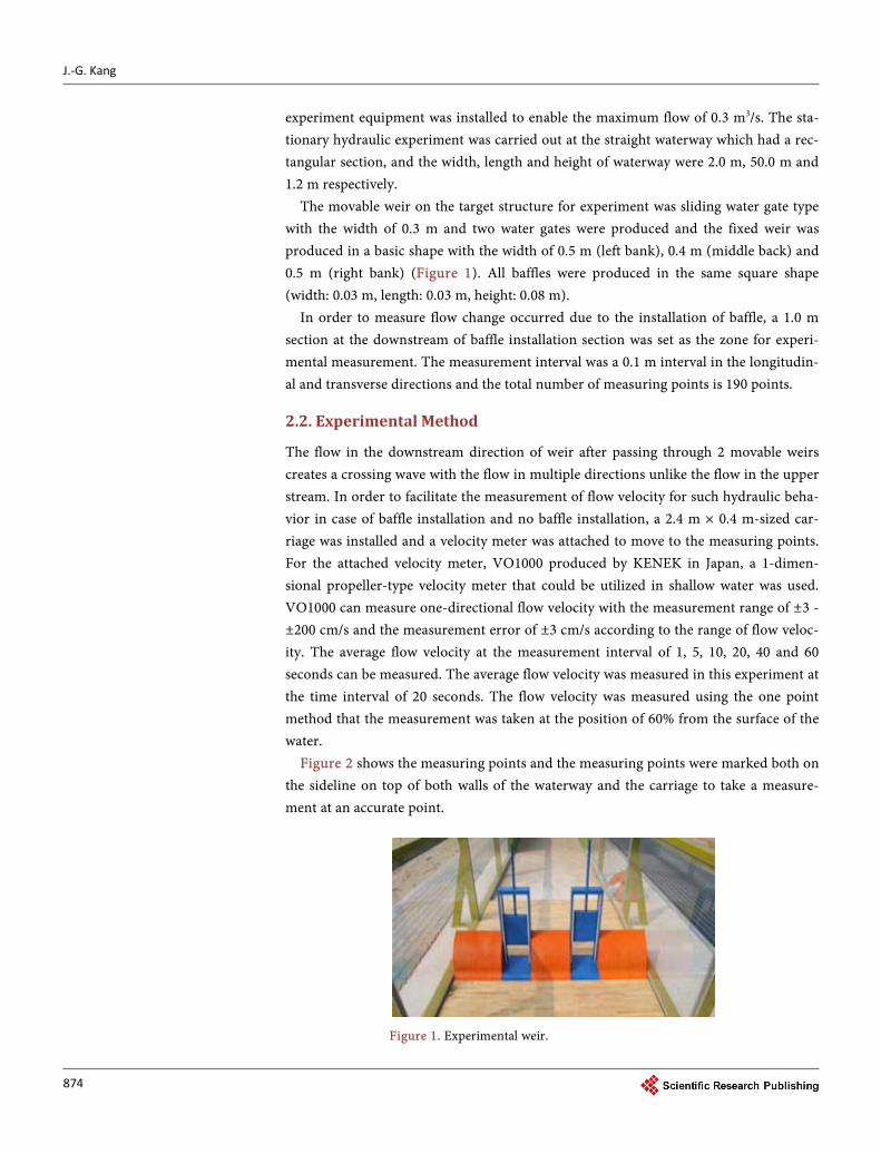
The movable weir on the target structure for experiment was sliding water gate type with the width of 0.3 m and two water gates were produced and the fixed weir was produced in a basic shape with the width of 0.5 m (left bank), 0.4 m (middle back) and 0.5 m (right bank) (Figure 1). All baffles were produced in the same square shape (width: 0.03 m, length: 0.03 m, height: 0.08 m).
In order to measure flow change occurred due to the installation of baffle, a 1.0 m section at the downstream of baffle installation section was set as the zone for experi-mental measurement. The measurement interval was a 0.1 m interval in the longitudin-al and transverse directions and the total number of measuring points is 190 points.
2.2. Experimental Method
The flow in the downstream direction of weir after passing through 2 movable weirs creates a crossing wave with the flow in multiple directions unlike the flow in the upper stream. In order to facilitate the measurement of flow velocity for such hydraulic beha-vior in case of baffle installation and no baffle installation, a 2.4 m × 0.4 m-sized car-riage was installed and a velocity meter was attached to move to the measuring points. For the attached velocity meter, VO1000 produced by KENEK in Japan, a 1-dimen- sional propeller-type velocity meter that could be utilized in shallow water was used. VO1000 can measure one-directional flow velocity with the measurement range of ±3 - ±200 cm/s and the measurement error of ±3 cm/s according to the range of flow veloc-ity. The average flow velocity at the measurement interval of 1, 5, 10, 20, 40 and 60 seconds can be measured. The average flow velocity was measured in this experiment at the time interval of 20 seconds. The flow velocity was measured using the one point method that the measurement was taken at the position of 60% from the surface of the water.
Figure 2 shows the measuring points and the measuring points were marked both on the sideline on top of both walls of the waterway and the carriage to take a measure-ment at an accurate point.
Figure 1. Experimental weir.

J.-G. Kang
875
Figure 2. Baffle installation section.
2.3. Experiment Conditions
One flow velocity condition was set in order to analyze the flow dissipation effect from the baffle arrangement at the downstream of the weir. The water gates are completely open and the rate of inflow is 0.15 m3/s. The water level at the upper stream was 0.3 m and the water level at downstream was 0.12 m (Table 1). Figure 3 shows the type of baffle arrangement in the hydraulic experiment. The experiment was carried out for a total of 9 conditions and case 1 is the condition before baffle installation.
3. Experiment Result and Analysis 3.1. Flow Velocity and Water Level Measurement Result for
Each Experiment Condition
In this experiment, water level difference between the upper stream and downstream was maximized in order to create strong flow velocity in the straight waterway. As a result of experiment, the maximum flow velocity at the downstream of the weir in Case 1 which was the case of no baffle installation was 2.068 m/s due to flow in multiple di-rections and crossing wave and since runoff flow was fast in the side walls of waterway,

J.-G. Kang
876
Case 2 Case 6
Case 3 Case 7
Case 4 Case 8
Case 5 Case 9
Figure 3. Arrangement type of the cases. Table 1. Condition of hydraulic model experiment.
Case Discharge
(m3/s) Upstream
water level (m) Downstream
water level (m) Height of Baffle (m)
1
0.15 0.30 0.12
X
2
0.08
3
4
5
6
7
8
9
J.-G. Kang
877
a vortex occurred on the left and right sides. Since the maximum water level did not encounter flow resistance, the water level was lower than the water level in the case that the baffles were installed.
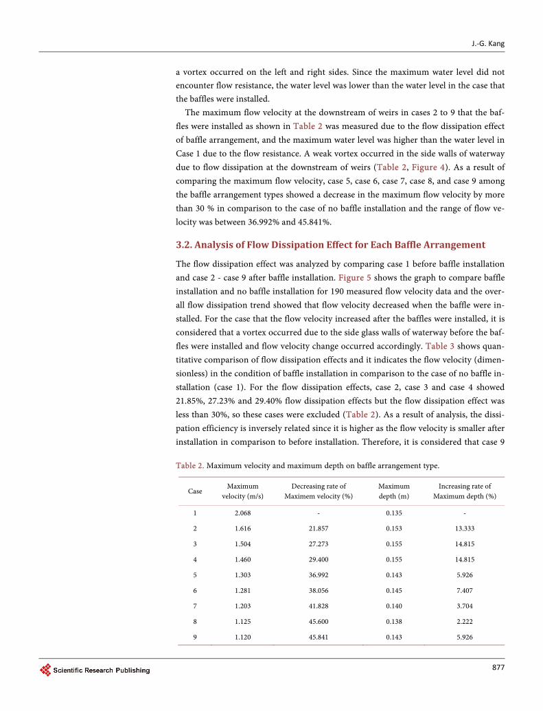
The maximum flow velocity at the downstream of weirs in cases 2 to 9 that the baf-fles were installed as shown in Table 2 was measured due to the flow dissipation effect of baffle arrangement, and the maximum water level was higher than the water level in Case 1 due to the flow resistance. A weak vortex occurred in the side walls of waterway due to flow dissipation at the downstream of weirs (Table 2, Figure 4). As a result of comparing the maximum flow velocity, case 5, case 6, case 7, case 8, and case 9 among the baffle arrangement types showed a decrease in the maximum flow velocity by more than 30 % in comparison to the case of no baffle installation and the range of flow ve-locity was between 36.992% and 45.841%.
3.2. Analysis of Flow Dissipation Effect for Each Baffle Arrangement
The flow dissipation effect was analyzed by comparing case 1 before baffle installation and case 2 - case 9 after baffle installation. Figure 5 shows the graph to compare baffle installation and no baffle installation for 190 measured flow velocity data and the over-all flow dissipation trend showed that flow velocity decreased when the baffle were in-stalled. For the case that the flow velocity increased after the baffles were installed, it is considered that a vortex occurred due to the side glass walls of waterway before the baf-fles were installed and flow velocity change occurred accordingly. Table 3 shows quan-titative comparison of flow dissipation effects and it indicates the flow velocity (dimen-sionless) in the condition of baffle installation in comparison to the case of no baffle in-stallation (case 1). For the flow dissipation effects, case 2, case 3 and case 4 showed 21.85%, 27.23% and 29.40% flow dissipation effects but the flow dissipation effect was less than 30%, so these cases were excluded (Table 2). As a result of analysis, the dissi-pation efficiency is inversely related since it is higher as the flow velocity is smaller after installation in comparison to before installation. Therefore, it is considered that case 9 Table 2. Maximum velocity and maximum depth on baffle arrangement type.
Case Maximum
velocity (m/s) Decreasing rate of
Maximem velocity (%) Maximum depth (m)
Increasing rate of Maximum depth (%)
1 2.068 - 0.135 -
2 1.616 21.857 0.153 13.333
3 1.504 27.273 0.155 14.815
4 1.460 29.400 0.155 14.815
5 1.303 36.992 0.143 5.926
6 1.281 38.056 0.145 7.407
7 1.203 41.828 0.140 3.704
8 1.125 45.600 0.138 2.222
9 1.120 45.841 0.143 5.926

J.-G. Kang
878
(a)
(b)
(c)
(d)
(e)
(f)

J.-G. Kang
879
(g)
(h)
(i)
Figure 4. Experimental result on arrangement type of the cases. (a) case 1 (Velocity and Depth); (b) case 2 (Velocity and Depth); (c) case 3 (Velocity and Depth); (d) case 4 (Velocity and Depth); (e) case 5 (Velocity and Depth); (f) case 6 (Velocity and Depth); (g) case 7 (Velocity and Depth); (h) case 8 (Velocity and Depth); (i) case 9 (Velocity and Depth). Table 3. Velocity after baffle installation.
Case UB/U Bn (UB/U)/Bn
5 0.630 54 0.012
6 0.619 35 0.018
7 0.582 63 0.010
8 0.544 62 0.010
9 0.542 63 0.009
has the highest flow velocity dissipation effect in comparison to the case of no baffle in-stallation, and considering the number of baffles, case 6 was the low- cost and high effi-ciency case.
4. Conclusions
The flow dissipation effect from the arrangement types of energy dissipater in multiple directions was analyzed in this study in order to improve the scouring problem at the downstream of weirs combined with movable weirs and fixed weirs.

J.-G. Kang
880
(a) (b)
(c) (d)
(e) (f)
(g) (h)
Figure 5. Comparison before installation and after installation of baffle. (a) Case 2; (b) Case 3; (c) Case 4; (d) Case 5; (e) Case 6; (f) Case 7; (g) Case 8; (h) Case 9.
The maximum flow velocity at the downstream of the weir in Case 1 which was the case of no baffle installation was 2.068 m/s due to flow in multiple directions and crossing wave and since runoff flow was fast in the side walls of waterway, a vortex oc-curred on the left and right sides. Since the maximum water level did not encounter
J.-G. Kang
881
flow resistance, the water level was lower than the water level in the case that the baffles were installed. The maximum flow velocity at the downstream of weirs in case 2 - case 9 that were the cases of baffle installation decreased in comparison to the case of no baffle installation, and the maximum water level increased in comparison to the case of no baffle installation due to flow resistance.
As a result of analyzing the dissipation effects due to baffle arrangement, case 5 - case 9 showed the dissipation effect of 30% or higher and case 9 showed the highest flow ve-locity dissipation effect. Also, as a result of comparing the dissipation efficiency by con-sidering the number of baffles, the “V-shaped” arrangement in case 6 could bring the most effective dissipation effect of flow velocity at the downstream with a less number of baffles when the number of baffles as shown in the experiment were installed.
The result of this study on the baffle installation and method for preventing scouring can be used as reference data for designing an energy dissipater in future. Also, the comparison between different number of baffles and relation analysis with the shape of baffle will be necessary additionally and the verification through full-scale experiment is also required.
Acknowledgements
This research was supported by the Internal Research Project (20160172-001) of the Korea Institute of Civil Engineering and Building Technology.
References [1] Kim, Y.B., Jung, S.G. and Shim, S.B. (2006) Prediction of River Bed Change due to Yong-
dam Dam Discharge. Journal of Korean Society of Hazard Mitigation, 6, 69-81.
[2] Lee, E.J. (2007) A Study on Local Scour of Fine-Grained Bed AROUND Bridge Pier Based on Shear Strength of Soil. Ph.D. Thesis, Seoul National University, Seoul.
[3] Cho, H.J. and Jun, W.Y. (2010) Flow Characteristics and Riverbed Change Simulation on Bridge-intensive Section. Journal of the Korean Society of Civil Engineers, 30, 589-598.
[4] Yoon, J.S., Song, H.G., Jeong, S.I. and Jung, J.S. (2014) Numerical Study on Pier-Scour of Mankyeong and Dongjin River According to Saemanguem Master Plan. Proceedings of the Korea Water Resources Association Conference, Pusan, 9-10 May 2014, 369-374.
[5] Lee, J.Y., Kim, K.Y., Son, S.H. and Shin, D.H. (2015) Prediction of Local Scour Develop-ment in Downstream due to Operation Rule of Movable Weir Gate. Journal of Korean So-ciety of Hazard Mitigation, 15, 221-230. https://doi.org/10.9798/KOSHAM.2015.15.4.221
[6] Korea Institute of Construction Technology (2005) The Multi-Function River Design Criteria. pp. 12-16 KICT.
[7] Kim, C.S., Kang, J.G., Yeo, H.K. and Yeo, W.K. (2010) An Experimental Study for the Em-pirical Equation to Quantify the Subsidence of Riprap Scour Protection at Downstream of Vertical Drop Structures. Journal of Korea Water Resources Association, 43, 433-443. https://doi.org/10.3741/JKWRA.2010.43.5.433
[8] McLaughlin Water Engineers (1986) Evaluation of and design recommendations for drop structures in the Denver Metropolitan Area. A Report Prepared for Denver Urban Drainage and Flood Control District.
[9] Agricultural Research Services (1991) ARS Construction Project Design Standard Manual.
J.-G. Kang
882
USDA, Beltsville.
[10] Little, W.C. (1982) Model Study of Low Drop Grade Control Structures. Journal of the Hy-draulics Division, 108, 1132-1146.
[11] Kim, J.H. (2004) Development of Stepped Drop Structure Effective for Energy Dissipation. Journal of Disaster Research, 6, 131-143.
[12] Lee, J. (2016) Analysis of Hydraulic Characteristics for the Secondary Stilling Basin Using Numerical Simulation. M.D. Thesis, Hongik University, Seoul.
[13] Cho, S. (2015) A Study on Hydraulic Energy Dissipation of Outflow Water by Baffle Block under Sluice Gate. M.D. Thesis, Incheon National University, Incheon.
[14] Alikhani, A., Behrozi-Rad, R. and Fathi-Moghadam, M. (2010) Hydraulic Jump in Stilling Basin with Vertical End Sill. Journal of Physical Sciences, 5, 25-29.
Submit or recommend next manuscript to SCIRP and we will provide best service for you:
Accepting pre-submission inquiries through Email, Facebook, LinkedIn, Twitter, etc. A wide selection of journals (inclusive of 9 subjects, more than 200 journals) Providing 24-hour high-quality service User-friendly online submission system Fair and swift peer-review system Efficient typesetting and proofreading procedure Display of the result of downloads and visits, as well as the number of cited articles Maximum dissemination of your research work
Submit your manuscript at: http://papersubmission.scirp.org/ Or contact [email protected]