effect of prior damage on the post-earthquake fire
DESCRIPTION
Effect of Prior Damage on the Post-earthquake FireResistance of Reinforced Concrete Portal FramesTRANSCRIPT

Investigating the Effect of Prior Damage on the Post-earthquake FireResistance of Reinforced Concrete Portal Frames
Hamid Reza Ronagh*, and Behrouz Behnam
(Received September 12, 2012, Accepted November 12, 2012)
Abstract: Post-earthquake fire (PEF) can lead to a rapid collapse of buildings that have been partially damaged as a result of a
prior earthquake. Almost all standards and codes for the design of structures against earthquake ignore the risk of PEF, and thus
buildings designed using those codes could be too weak when subjected to a fire after an earthquake. An investigation based on
sequential analysis inspired by FEMA356 is performed here on the immediate occupancy (IO), life safety (LS) and collapse
prevention (CP) performance levels of two portal frames, after they are pushed to arrive at a certain level of displacement
corresponding to the mentioned performance level. This investigation is followed by a fire analysis of the damaged frames,
examining the time taken for the damaged frames to collapse. As a point of reference, a fire analysis is also performed for
undamaged frames and before the occurrence of earthquake. The results indicate that while there is minor difference between the
fire resistances of the fire-alone situation and the frames pushed to the IO level of performance, a notable difference is observed
between the fire-alone analysis and the frames pushed to arrive at LS and CP levels of performance and exposed to PEF. The
results also show that exposing only the beams to fire results in a higher decline of the fire resistance, compared to exposing only
the columns to fire. Furthermore, the results show that the frames pushed to arrive at LS and CP levels of performance collapse in a
global collapse mode laterally, whereas at the IO level of performance and fire-alone situation, the collapse mechanism is mostly
local through the collapse of beams. Whilst the investigation is conducted for a certain class of portal frames, the results confirm
the need for the incorporation of PEF into the process of analysis and design, and provide some quantitative measures on the level
of associated effects.
Keywords: post-earthquake fire, sequential analysis, fire resistance, reinforced concrete structures, performance-based design,
immediate occupancy, life safety, collapse prevention.
1. Introduction
Fire in buildings is a reality and occur for many differentreasons, most of which are not considered to be localized andnot so serious from an urban perspective. This is mostlybecause there are usually adequate fireproofing systems inbuildings, such as sprinklers and vertical pipes, and there existrescue teams and fire brigades in cities to either extinguish orcontrol the fire. Collectively, these safeguards reduce the pos-sibility of a widespread fire. When it comes to fire after anearthquake, however, the number of available rescue teamsdrops, depending on the severity of earthquake, as rescue teamswill also be involved with helping people trapped under therubble. In addition, there is a high probability of active fire-extinguishing systems, such as sprinklers, not working aselectricity or water supplies might be cut. Thus, providingadequate time for extinguishing the fire and/or evacuating
people trapped in the fire must be a key aspect of a post-earthquakefire (PEF) safety strategy. Past statistics have provedthat PEF can create even more damage compared to theearthquake alone (Fitzpatrick 1914). The effect of PEF onbuildings can be categorized into two: the damage owing to theburning of non-structural materials such as furniture and pos-sessions; and the damage caused by excess structural loads onthe building (Chen et al. 2004). The latter is important as themajority of structural members are not designed for extremeconditions, combining gravity loads, lateral loads and after-shock loads. Consequently, buildings that have been moder-ately damaged by an earthquake can be destroyed rapidly in asubsequent fire. From a different perspective, as earthquake cancause serious damage to lifeline structures, arterial roads andbridges, fire brigades would have increased difficulty in con-trolling fires. Accordingly, it will take considerably more timeto control a PEF than other more usual kinds of fires. In addi-tion, since helping people trapped under the rubble will takepriority; untended firesmay lead to a conflagration. In this case,it is difficult to estimate the size of the catastrophe (Scawthorn2008). Therefore, buildings must be able to structurally resistfire for a period far longer than is the norm for fire-only design.On the other hand, using the philosophy of design based
on performance (California Seismic Safety Commission
The University of Queensland, Brisbane, QLD, Australia.
*Corresponding Author; E-mail: [email protected]
Copyright � The Author(s) 2012. This article is published
with open access at Springerlink.com
International Journal of Concrete Structures and MaterialsVol.6, No.4, pp.209–220, December 2012DOI 10.1007/s40069-012-0025-9ISSN 1976-0485 / eISSN 2234-1315
209

1996), structural elements are normally designed to satisfyvarious levels of performance, some of which are operational(O), immediate occupancy (IO), life safety (LS) and collapseprevention (CP). According to the performance design cri-teria, the expected performance of structures shall be con-trolled by the assignment of each structure to one of several‘‘Seismic Use Groups’’. In FEMA450 (2003), for example,there are three ‘‘Seismic Use Groups’’, which are categorizedbased on the occupancy of the structures within the groupand the relative consequences of earthquake-induced dam-age to the structures. Design codes specify progressivelymore conservative strength, serviceability, and detailingrequirements for structures in order to attain minimum levelsof earthquake performance suitable to the individual occu-pancies. Structures contained in these groups are not specificto a certain seismic zone; rather they are spread across allzones from high to low hazard and, as such, the categori-zations do not really relate to hazard. Rather the groupings,categorized by occupancy or use, are used to establish designcriteria intended to produce specific types of performance in‘‘design earthquake’’ events, based on the importance ofreducing structural damage and improving LS (Fig. 1).The various performance levels required for buildings of
different categories can implicitly be met by increasing the‘‘design earthquake’’ by a factor called the ‘‘importance fac-tor’’. The importance factor adjusts the intensity of earthquakein the design so that the required performance level under the‘‘design earthquake’’ is met. Specifically, in important struc-tures, it is expected that after an earthquake only minordamage will be sustained by the structural elements. Minordamage is quantified with a value of drift limited to 1 %according to FEMA356 (2000). This is the boundary of IO andLS levels of performance. At this level of drift, while someelements go beyond the yield point in the correspondingpushover curve, non-structural components may not operateproperly owing to mechanical failure or lack of amenities,such as disconnection of electricity (Behnam 2006). There-fore, when designed well, important structures are expected toremain habitable after the shock (FEMA356 2000). Structuressuch as schools fall into this category (Organisation for Eco-nomic Co-operation and Development 2004). Most buildingsin urban areas, however, are residential or commercialbuildings, designed to meet the LS level of performance. Themain objective at this performance level is to limit both the
amount of damage in buildings and as suchmore safety for theinhabitants. To meet this objective, limiting the value of driftto around 2 % is recommended by FEMA356 as a margin forLS and CP levels of performance. At the LS level, it isexpected that, along with some residual displacement in thebuilding, there is considerable damage to both structural andnon-structural elements. However, there should be adequateresistance left in the structure to carry the applied gravity loadswithout any failure. Obviously, buildings designed for CPperformance level, sometimes called limited safety, will sus-tainmore damage compared to other levels of performance. Atthis level, it is expected that the imposed drift would be morethan 4 %, which can lead to extensive damage of the structuralcomponents.Understanding the structural behavior of buildings
becomes more important when a fire occurs after a seismicevent, because the fire increases the level of complexity. Ingeneral, ‘‘fire-resistance rating’’ is defined as the period oftime in which the integrity of a member subjected to fire ismaintained to resist applied loads (Konig 2005; Kodur andDwaikat 2007). This definition is correlated with variousfactors, one of which is the type of building being designed(McGhie 2007). Indeed, the purpose of fire resistance is notonly to provide sufficient time to evacuate people trappedinside the burning building, but also to reduce the possibilityof any conflagration (Eidinger 2004). Although typically,fire-resistance ratings are presented in national buildingcodes, such as National Research Council Canada (2005)and International Building Code (IBC) (2006), many of themprovide only for fire condition and not for PEF. This iscritically important as the vulnerability of earthquake-dam-aged structures exposed to PEF is much more than thoseexposed to fire alone. This is because earthquake excitationmay produce residual lateral deformations as well as residualstresses on the members (Mousavi et al. 2008). Moreover,experiences from past earthquakes confirm that both activeand passive fireproofing systems, such as sprinklers and firecontrol systems, may become seriously damaged, therebyconsiderably decreasing the fire-resistance capability.Therefore, evaluation of a building’s performance under PEFis essential, requiring careful scrutiny.The PEF resistance of a building is dependent on various
factors, including the deformed geometry and the degrada-tion in stiffness resulting from earthquake (Zaharia and
Fig. 1 Building performance levels versus earthquake severity (FEMA450 2003).
210 | International Journal of Concrete Structures and Materials (Vol.6, No.4, December 2012)

Pintea 2009). In reinforced concrete structures, in addition tothe aforementioned factors, the effects of the level of dam-age, including tensile cracking, removal of rebars cover andcompressive crushing have to be considered as well.Assuming ductile behavior of RC elements which is oftenintended in design, a typical moment–curvature relation canbe idealized to separate stages of pre-cracking of concrete,post cracking, yielding of steel reinforcement and concretecrushing in compression (Kwak and Kim 2002). While itseems that tensile cracking, as the first stage of cracking,has no significant effect on the PEF resistance, majorcracking resulting in removal of rebars cover or crushing ofconcrete in compression drastically reduces the PEF resis-tance (Ervine et al. 2011).Performance of buildings subjected to fire after earthquake
has been investigated by researchers in the past, but hasreceived more attention since the horrific event of ‘9/11’. Forexample, Della Corte et al. (2003) investigated unprotectedsteel moment-resistant frames and their responses whensubjected to fire following an earthquake. Assuming elasticperfectly plastic (EPP) behavior of steel and considering P-Deffect with P from gravity loads and D from the earthquake,the fire-resistance rating was found using numerical meth-ods. Ignoring the degradation of stiffness in Della Corte et al.study is an issue subject to discussion (Fig. 2).Further study of steel frames was carried out by Zaharia
and Pintea (2009). They investigated two different steelframes, designed for two return periods of ground motion:2,475 and 475 years. The seismic response of each structurewas then evaluated by a pushover analysis developed byFajfar (1996). While the frame designed for the 2,475 yearsreturn period remained elastic in the pushover analysis, theweaker frame designed for the 475 years return period sus-tained notable inter-story drift. They then performed a fireanalysis on both frames, which confirmed that the fireresistance of the structures, considering their deformed state
under earthquake, is notably lower than that of structuresthat do not have any history of deformation prior to theapplication of the fire. Mostafaei and Kabeyasawa (2012)investigated the PEF resistance of reinforced concretestructures with shear wall. Their model was first subjected toan equivalent Kobe 1995 earthquake on a shaking table. Thedamage sustained by the structure was then quantified byobservation, through use of a method called axial-shear-flexure interaction (ASFI) (Kabeyasawa and Mostafaei2007) in a numerical thermal analysis to find the temperaturerise in and around both the cracked and the intact sectionssubjected to fire. Fire loading was then applied to thedamaged structure in order to consider the effect of con-crete’s degraded compressive strength. The results showedthat the ability of the structure to sustain gravity loads in thecracked components is considerably lower than in the intactcomponents. Although the compressive strength of concreteplays an important role in the overall fire resistance, otherfactors (such as P-D effect and changes in the modulus ofelasticity) have to be considered in order to improveaccuracy.In the same year, Faggiano and Gregorgio (2010) inves-
tigated steel structures exposed to PEF. They performed acoupled analysis consisting of both earthquake and fire.Based on FEMA356 procedure, Faggiano and Gregorgiodeveloped a method for evaluating the performance ofbuildings subjected to earthquake, and for suggesting fireperformance levels for various conditions of fire. Clearly, ina coupled analysis, both residual deformation and degrada-tion of mechanical characteristics are applied. However, themethod can be more effective for steel structures because, aswas previously mentioned, in reinforced concrete structures,seriously damaged sections play an important role in PEFresistance. Recently, Ervine et al. (2011), conducted anexperimental and numerical study of a reinforced concreteelement subjected to conventional loads followed by a fireload. After applying two concentrated vertical loads on thespecimen and recording the subsequent deflection, the cre-ated cracks were observed through the member. The modelwas then subjected to fire loading in order to find the effectof the created cracks on the thermal propagation inside thesection. The results showed that minor tensile crackingwould not significantly change the heat penetration insidethe section. They concluded that the fire resistance of theintact specimen and of the minor damaged specimen wereroughly identical (Ervine et al. 2012). However, exposingthe rebar directly to fire, e.g. in the case of crushing of thecover, changes both the thermal and the structural behaviorof the specimen considerably. Another study is currentlybeing undertaken by Bhargava et al. (2012) on the fireresistance of an earthquake-damaged RC frame. A nearlyfull-scale portal frame was first loaded by the relevantgravity loads and then subjected to a cyclic lateral load,based on the Indian standard in a quasi-static fashion. Theload-control mode was considered to meet 2 % drift, cor-responding to the LS performance level as described inFEMA356 (2000) code. The cracks widths were thenobserved using optical tools, non-destructive tests and
Gravity Loads
Gravity Loads
h1
h2
h3
Gravity Loads
δ1
δ2
δ3
Fig. 2 Residual deformation resulting from the earthquake(Della Corte et al. 2003).
International Journal of Concrete Structures and Materials (Vol.6, No.4, December 2012) | 211

ultrasound. A computational analysis was also performedusing the finite element method with (ABAQUS 2008) tocompare the test and the analytical results. The results showa good conformity with FEMA356 descriptive definitions ofdamage levels at various performance levels, such as IO andLS. They suggested that the results of a quasi-static cyclictest can be used for the subsequent fire analysis.Aligned with the abovementioned studies and the
FEMA356 performance level definition, in this study, aseries of numerical investigations is carried out on the PEFresistance of two portal frames, designed for different per-formance levels. The study here includes a sequential anal-ysis comprising both earthquake and the aftermath fire andusing FEMA356 descriptive performance levels. As well,consideration is given to effects such as the removal of coveron the PEF resistance.
2. Methodology
2.1 Sequential AnalysisSequential analysis is a useful method for considering the
effect of both earthquake and fire on a structure. Figure 3schematically shows stages of the nonlinear sequentialanalysis. The first stage of loading is the application ofgravity loads, which are assumed to be static and uniform. Apseudo earthquake load then follows in a pushover style,reaching its maximum value and returning to zero in a shorttime. Clearly, during this time, gravity loads are also applied.The pattern that is chosen for applying the earthquake load issimilar to pushover analysis, with the difference that thestructure is unloaded after reaching a certain level of load.Here, it is assumed that the maximum level of earthquakeload corresponds to the defined performance level, i.e. IO,LS or CP, according to FEMA356 (2000). This assumptionis in line with the seismic design philosophy in which theperformance level of structures shall not exceed the assumedlevel when subjected to the ‘‘design earthquake’’. Therefore,the structures are pushed to these levels and then unloaded.Load duration is not important for either gravity or
earthquake loads, because in this study long-term effectssuch as creep and shrinkage are not included in the analysis.Thus, any arbitrary load duration could be chosen for theseloads. It should be noted that no dynamic effects are con-sidered in this study. Finally, as can be seen in Fig. 3c, thefire load is applied to the structure. Prior to fire loading,
properties of the structures are set to the reference temper-ature, but during fire, the mechanical properties vary withtemperature.In this study, SAFIR software (Franssen 2011) is used to
perform the seismic and subsequent fire analysessequentially.
2.2 Material NonlinearityFiber element is the most capable model for the nonlinear
analysis of reinforced concrete members. Many researchershave developed the finite element formulation for this ele-ment. The model accounts for material nonlinearities in rebarsteel and concrete (Zhao and Sritharan 2007; Lin et al. 2009;Godat 2008). A fiber beam element is made up of a series ofsections along the element length, whose number and loca-tion depend on the integration scheme. The constitutiverelation of the section is not specified explicitly, but isderived by integration of the response of the fibers, whichfollow the uniaxial stress–strain relation of the particularmaterial. The consecutive material stress–strain curves areused to generate the moment–curvature and the axial force–deformation relationships. Concrete can be modeleddepending on the region: the core (that is confined); and thecover (that is unconfined). In the SAFIR program, the stress–strain relationship for concrete and rebar steel are embeddedaccording to Eurocodes (Minson 2006). Using the fibermodel, the spread of plasticity can be modeled appropriately.Unlike the lumped plasticity model, in the fiber elementmodel, the plasticity is spatially distributed both in crosssection and along the member.
2.3 Pushover AnalysisStatic pushover analysis is one of the non-linear static
methods used for analyzing structures subjected to seismicloads. This method is becoming a popular tool for theseismic performance evaluation of existing and new struc-tures (Fardis 2007). In this method, using a specific loadpattern, the structure is pushed to a value of displacementcalled the target displacement. The target displacementserves as an estimate of the global displacement that thestructure is expected to experience in a ‘‘design earthquake’’,often shown by the roof displacement at the center of massof the structure. In this study, a vertical distribution of loads,proportional to the shape of the fundamental mode in thedirection under consideration, is used. Figure 4 shows astructural frame subjected to a lateral load pattern and a
(a) (b) (c)
Load
Time
Dead & Live
Load
Time
Performance Level
t1 t2
Temperature
Time
Fire Pattern
t2
Fig. 3 Stages of the sequential analysis. a Gravity loading (is constant during the time). b Earthquake loading (is applied for ashort time). c Fire loading (is applied after the unloading process of earthquake loads).
212 | International Journal of Concrete Structures and Materials (Vol.6, No.4, December 2012)

typical base shear versus top story displacement. In thisstudy, the IO, LS and CP performance levels are consideredfor seismic analysis prior to fire loading. Clearly, in struc-tures that experience plastic deformations, residual defor-mation remains in the structure and thus the structures do notreturn to their initial condition. Using the definition oflumped plasticity, the potential locations of plasticity areintroduced by plastic hinges in SAP2000 (2002).
The moment-rotation behavior of each plastic hinge fol-lows FEMA definition. Figure 5 shows a typical force–deformation curve for an assumed hinge. This figure alsoshows the performance levels as mentioned earlier.These definitions in a concrete cross section are required
for the PEF analysis, because variation of temperature acrossthe section is highly dependent on the state of damage. InFEMA356, it is stated that in the IO performance level,minor damage in the structural elements is observed, whichhas no significant effect on PEF resistance (Ervine et al.2012). On the other hand, in the LS performance level,extensive damage is observed in beams and ductile columns,resulting in spalling of their cover. In addition, for structuresdesigned for CP level of performance, it is expected that thestructure would sustain considerable damage in beams andcolumns, much more than for IO or LS levels of perfor-mance. The dotted lines and the arrows in Fig. 6 show theassumed pattern of applied fire frontier for damaged beamsand columns after the pushover analysis. This assumption isbased on the authors’ interpretation of the informationavailable in the FEMA356 code, the Japan Building DisasterPrevention Association (JBDPA) and an experimental studyperformed by Bhargava et al. (2012). While none of theaforementioned references differentiates between the beamand the column responses as to the extent of cracking orconcrete spalling, they all point to the fact that the concretecover is no longer part of the section. In FEMA356, ‘‘TableC1–3 structural performance levels and damage’’, the dif-ferent levels of damage in columns and beams are explained.Relating to quantity rather than quality, Bhargava et al.(2012) conducted an experimental study on a nearly full-scale RC frame, in order to find the level of damage whenthe frame was pushed to a certain level of displacement.Their results show that while at a roof drift ratio of 1.37 %,flexural cracking was observed (corresponding to the driftratio in IO level of performance), at 2.11 % drift ratio(corresponding to the drift ratio of LS level of performance)spalling and wide cracks in columns and beams wereobserved. The study does not reveal any differences betweenthe columns and the beams. Based on JBDPA, Meada andKang (2009) and Nakano et al. (2004) showed in severalstudies that when a structure sustains severe damage (cor-responding to the CP performance level in FEMA356)
Fig. 4 Conceptual pushover curve.
Fig. 5 Conceptual plastic hinge states. O operational, IOimmediate occupancy, LS life safety, CP collapseprevention.
(a) (b) (c)Fig. 6 Schematically applied fire frontiers on the sections in various performance levels. a IO level of performance. b LS level of
performance. c CP level of performance. Note the arrows show fire frontiers.
International Journal of Concrete Structures and Materials (Vol.6, No.4, December 2012) | 213

crushing and spalling of the concrete cover with consequentexposed reinforcement is observed.Overall, the PEF analysis in structures designed for IO
level of performance is only followed by a minor residualdisplacement, while at LS level of performance, along withsome residual deformation and degradation in strength andstiffness, the removal of cover in a region around the plastichinges should be considered. At CP level of performance,however, the structures not only sustain severe damage andconsiderable degradation in strength and stiffness, but rebarsalso need to be considered totally exposed in the PEFanalysis.
2.4 Reinforced Concrete Behavior Underthe Effect of FireMaterials thermal and mechanical characteristics change
considerably when exposed to fire, which in many casesproduce high levels of thermal stress (Kwasniewski 2011).In addition, when a heterogeneous composite material withdifferent thermal characteristics is subjected to elevatedtemperature, differential thermal stresses speed up the deg-radation. Concrete has low thermal conductivity, whichcreates slow transmission of heat inside the cross section(Faggiano and Gregorgio 2010). The reinforcement barshave high thermal conductivity, but they are generally pro-tected by the concrete cover. Cracking or crushing of theconcrete cover, however, causes more thermal propagationto penetrate at a quicker rate with serious negative outcomes.It is apparent that this penetration can be worse if a memberthat has been previously damaged (for example, as a result ofearthquake loading), experiences high temperature, becausethe fire resistance of seriously damaged members is muchless than that of intact members. In other words, the higherthe number of damaged members and the greater the extentof damage in these members, the shorter will be the time tocollapse during the PEF. In particular, for reinforced bars, thecritical temperature is around 500 �C, at which steel’s ulti-mate strength decreases by 50 %, while for concrete, thecritical temperature is about 300 �C (Youssef and Moftah2007). ‘‘Critical temperature’’ is defined as the temperaturebeyond which the values of strength are considerably
reduced. Figure 7 shows the stress–strain relationship in hot-rolled bars and concrete at high temperatures, as developedby Eurocodes 2 and 3. It is also worth mentioning thatspalling of concrete cover under fire exposure is an impor-tant issue, which occurs suddenly, violently, is brittle andmay lead to a significant decrease in the load-bearing of thestructure (Debicki et al. 2012). The thermal spalling, nev-ertheless, is more important in the elements with more than4–5 cm cover (Majorana et al. 2010) or made of high-strength concrete (HSC) (Kodur 2005) with particles smallerthan the cement grains (micro silica, for example) andmoisture content of more than 3–4 % (Hertz 2003; Hertz andSørensen 2005). As for the elements of this study, which aremade from normal-strength concrete (NSC) with the coverof 4 cm and moisture of 2 %, thermal spalling is notconsidered.
2.5 Fire PatternsSeveral methods have been developed to calculate the
thermal actions produced by a fire on a compartment (Re-mesh and Tan 2007; Lundin 2005). These methods havebeen established either using parametric fires called ‘‘time–temperature curves’’, such as those mentioned in ISO 834International Standard (1999) and ASTM E119 (ASTM2006) (based on experiment and tests), or using ‘‘naturalfires’’ which rely mainly on the volume of gas produced bythe combustible materials in a covered space, such as thosestated in SEI and ASCE (2006). Both models are representedassuming a fully developed fire, as schematically shown inFig. 8. The temperatures produced from burning combusti-ble materials are combined into one single parameter(Buchanan 2001).The cooling phase in Fig. 9 (the dotted line) is based on
the assumption that after a fire has been burning for sometime, either air or combustible material will become lessavailable and thus, the temperature or fire load will decrease.This assumption is more realistic in the case of fire beforeearthquake, assuming closed openings. However, in build-ings previously damaged by an earthquake, there is a highprobability of window breakage. As a result, the pattern offire progression is different compared to a ‘‘normal’’ fire.
Fig. 7 Stress–strain relationship at different temperatures (Minson 2006). a Concrete. b Hot-rolled bar.
214 | International Journal of Concrete Structures and Materials (Vol.6, No.4, December 2012)
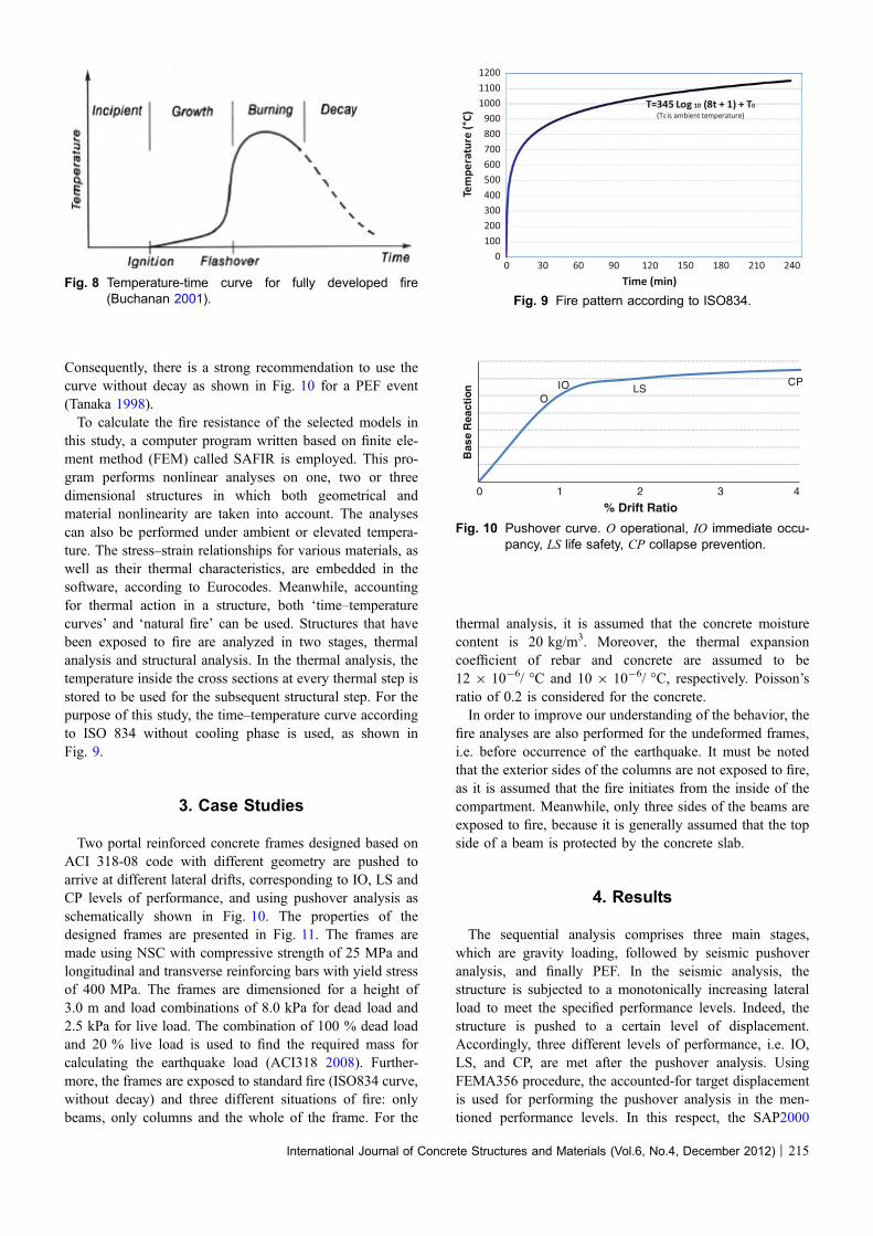
Consequently, there is a strong recommendation to use thecurve without decay as shown in Fig. 10 for a PEF event(Tanaka 1998).To calculate the fire resistance of the selected models in
this study, a computer program written based on finite ele-ment method (FEM) called SAFIR is employed. This pro-gram performs nonlinear analyses on one, two or threedimensional structures in which both geometrical andmaterial nonlinearity are taken into account. The analysescan also be performed under ambient or elevated tempera-ture. The stress–strain relationships for various materials, aswell as their thermal characteristics, are embedded in thesoftware, according to Eurocodes. Meanwhile, accountingfor thermal action in a structure, both ‘time–temperaturecurves’ and ‘natural fire’ can be used. Structures that havebeen exposed to fire are analyzed in two stages, thermalanalysis and structural analysis. In the thermal analysis, thetemperature inside the cross sections at every thermal step isstored to be used for the subsequent structural step. For thepurpose of this study, the time–temperature curve accordingto ISO 834 without cooling phase is used, as shown inFig. 9.
3. Case Studies
Two portal reinforced concrete frames designed based onACI 318-08 code with different geometry are pushed toarrive at different lateral drifts, corresponding to IO, LS andCP levels of performance, and using pushover analysis asschematically shown in Fig. 10. The properties of thedesigned frames are presented in Fig. 11. The frames aremade using NSC with compressive strength of 25 MPa andlongitudinal and transverse reinforcing bars with yield stressof 400 MPa. The frames are dimensioned for a height of3.0 m and load combinations of 8.0 kPa for dead load and2.5 kPa for live load. The combination of 100 % dead loadand 20 % live load is used to find the required mass forcalculating the earthquake load (ACI318 2008). Further-more, the frames are exposed to standard fire (ISO834 curve,without decay) and three different situations of fire: onlybeams, only columns and the whole of the frame. For the
thermal analysis, it is assumed that the concrete moisturecontent is 20 kg/m3. Moreover, the thermal expansioncoefficient of rebar and concrete are assumed to be12 9 10-6/ �C and 10 9 10-6/ �C, respectively. Poisson’sratio of 0.2 is considered for the concrete.In order to improve our understanding of the behavior, the
fire analyses are also performed for the undeformed frames,i.e. before occurrence of the earthquake. It must be notedthat the exterior sides of the columns are not exposed to fire,as it is assumed that the fire initiates from the inside of thecompartment. Meanwhile, only three sides of the beams areexposed to fire, because it is generally assumed that the topside of a beam is protected by the concrete slab.
4. Results
The sequential analysis comprises three main stages,which are gravity loading, followed by seismic pushoveranalysis, and finally PEF. In the seismic analysis, thestructure is subjected to a monotonically increasing lateralload to meet the specified performance levels. Indeed, thestructure is pushed to a certain level of displacement.Accordingly, three different levels of performance, i.e. IO,LS, and CP, are met after the pushover analysis. UsingFEMA356 procedure, the accounted-for target displacementis used for performing the pushover analysis in the men-tioned performance levels. In this respect, the SAP2000
Fig. 8 Temperature-time curve for fully developed fire(Buchanan 2001). Fig. 9 Fire pattern according to ISO834.
OIO LS
CP
0 1 2 3 4
Bas
e R
eact
ion
% Drift Ratio
Fig. 10 Pushover curve. O operational, IO immediate occu-pancy, LS life safety, CP collapse prevention.
International Journal of Concrete Structures and Materials (Vol.6, No.4, December 2012) | 215

(2002) program is employed to perform the nonlinearpushover analysis. Furthermore, FEMA procedure is used todefine the hinges for the nonlinear pushover analysis. Thelateral forces corresponding to the target displacement atevery performance level are extracted from the SAP2000(2002) program, and are then input to the SAFIR programfor performing the sequential analysis. Final stage of thesequential analysis is to apply a PEF to the frames. Asmentioned, several scenarios are used for the fire analysis; inone case, the undamaged frame is subjected to fire loading,while in the second case, the damaged frame is exposed tofire load. In this way, in the first case, the fire load followsthe gravity loads, but in the second case, the fire load followsgravity and earthquake loads. Figure 12 shows the temper-ature distribution in a column at different levels of damage,from minor to major.Figures 13 and 14 show displacement against time for the
case of L = 1.5H, which implies the fire resistance of the
frames in seconds for both scenarios (fire and PEF). Thefire resistance is defined as the time at which the dis-placements, either globally (i.e. the drift of a certain point)or locally (i.e. the deformations at the middle of a beam),go beyond chosen thresholds. The thresholds have beenidentified by the curve for displacements versus time stepmerging towards a vertical asymptote by 1 % error. Thesethresholds implicitly represent the definition of fire resis-tance of a member as described earlier, where the memberis not able to resist the initially applied gravity loads(Kodur and Dwaikat 2007). As is seen in the figures,regardless of subjecting a structure to fire alone or PEF,there is a correlation between the fire-resistance rating andthe performance levels. Indeed, along with increasing thelateral displacement in the frames, the fire resistancedecreases such that the fire resistance of the frames pushedto CP level of performance is much lower than that of theframes pushed to LS or IO levels of performance. The
L = 1.5HH
30x30 (cm)
30x3
0 (c
m)
30x3
0 (c
m)
L = 2.5 H
H
35x35 (cm)
35x3
5 (c
m)
35x3
5 (c
m)
Fig. 11 Geometric properties of selected frames, H = 3.0 m. Note for all the structural members, 4 cm cover is assumed.
(a) (b) (c) (d)Fig. 12 Distribution of temperature in a column according to ISO 834. a IO level of performance. b LS level of performance. c CP
level of performance. d Temperature.
-0.25
-0.2
-0.15
-0.1
-0.05
0
Dis
plac
emen
t (m
)
Time (Sec)
Fire alone
IO
LS
CP
Failure shape-0.07
-0.06
-0.05
-0.04
-0.03
-0.02
-0.01
0
Dis
plac
emen
t (m
)
Time (Sec)
Fire alone
IO
LS
CPFailure shape
0 3600 7200 10800 14400 0 3600 7200 10800 14400
Fig. 13 Fire resistance of the case ‘‘L = 1.5H’’, members separately exposed to fire. a Only the beam exposed to fire. b Only thecolumns exposed to fire. IO immediate occupancy, LS life safety, CP collapse prevention.
216 | International Journal of Concrete Structures and Materials (Vol.6, No.4, December 2012)

figures also show a minor difference between the fireresistance at IO level of performance and fire alone. That ismostly because at IO level of performance, only minordamage occurs, resulting in insignificant residual displace-ment and/or degradation in strength and stiffness. It is alsoseen that fire resistance declines considerably when onlythe beam is exposed to fire, compared to exposing thecolumns to fire. In other words, it seems that the beam ismore sensitive to fire than the columns. Interestingly,Figs. 13 and 14 show that there is similarity in fire resis-tance when all members are exposed to fire and when onlythe beam is exposed to fire. This implies that the fire
resistance of a frame is mostly dependent on the fireresistance of the beams. In the figures, the shape of failureis shown. As is seen, two types of failure are observed;local and global. While local collapse depends largely onthe collapse of beams (Figs. 13a, b, 15a), global collapse ismainly governed by considerable lateral displacement ofthe columns (Fig. 15b). It is evident that the frame failslocally in case of fire alone and the IO level of perfor-mance. However, it fails globally when pushed to LS or CPlevels of performance. The sharp increase and thendecrease in Fig. 15b represents the displacement resultedfrom lateral pushover.
-0.45
-0.4
-0.35
-0.3
-0.25
-0.2
-0.15
-0.1
-0.05
0
Dis
plac
emen
t (m
)Fire alone
IO
LS
CP
Failure shape
-0.12
-0.1
-0.08
-0.06
-0.04
-0.02
0
Dis
plac
emen
t (m
)
Time (Sec)Time (Sec)
Fire alone
IO
LS
CPFailure shape
0 3600 7200 10800 14400 0 3600 7200 10800 14400
Fig. 14 Fire resistance of the case ‘‘L = 1.5H’’, members separately exposed to fire. a Only the beam exposed to fire. b Only thecolumns exposed to fire. IO immediate occupancy, LS life safety, CP collapse prevention.
-0.3
-0.25
-0.2
-0.15
-0.1
-0.05
0
Dis
plac
emen
t (m
)
Time (Sec)
Fire alone
IO
Failure shape-0.02
0
0.02
0.04
0.06
0.08
0.1
0.12
0 3600 7200 10800 14400
0 3600 7200 10800 14400
Dis
plac
emen
t (m
)
Time (Sec)
LS
CP
Failure shape
Fig. 15 Fire resistance of the case ‘‘L = 2.5H’’, all the members exposed to fire. a Fire alone and IO level. b LS and CP level. IOimmediate occupancy, LS life safety, CP collapse prevention.
-0.4
-0.35
-0.3
-0.25
-0.2
-0.15
-0.1
-0.05
0
Dis
plac
emen
t (m
)
Fire alone
IO
Failure shape-0.02
0
0.02
0.04
0.06
0.08
0.1
0.120 3600 7200 10800 14400
0 3600 7200 10800 14400
Dis
plac
emen
t (m
)
Time (Sec)Time (Sec)
LS
CP
Failure shape
Fig. 16 Fire resistance of the case ‘‘L = 2.5H’’, all the members exposed to fire. a Fire alone and IO level. b LS and CP level. IOimmediate occupancy, LS life safety, CP collapse prevention.
International Journal of Concrete Structures and Materials (Vol.6, No.4, December 2012) | 217

Figures 14 and 16 show the fire resistance of the frame withL = 2.5H, for different positions of fire. Similar to the framewith L = 1.5H, the fire resistance reduces when the frame ismore pushed laterally. Again, there is similarity between thefire resistance when the whole frame is exposed to fire and thatwhen only the beam is exposed to fire, which again signifiesthat the fire resistance of the frames depends mostly on the fireresistance of the beam. As a specific note with regard toFig. 16b, it is useful to mention that while the frame fails incase of PEF at the LS or CP level of performance, no failure isobserved even after 4 h in case of fire alone or PEF at IO levelof performance. Besides, as it is seen in Figs. 14 and 16,global collapse is observed in the frame if pushed to the LS orCP level of performance. However, the frame fails locally inthe other fire scenarios.In general, the fire resistance of the frame with L = 2.5H
is greater than that of the frame with L = 1.5H because ofmore stiffness in the frame with L = 2.5H. However, thereis a close similarity between the fire resistances of bothframes when subjected to PEF.
5. Conclusion
Post-earthquake fire is one of the most problematic situ-ations in seismic regions. In this research, sequential non-linear analysis is proposed for PEF. Two RC frames(L = 1.5H and L = 2.5H, where H = 3.0 m) were selectedand then pushed to arrive at three different lateral displace-ments corresponding to three different performance levels,i.e. IO, LS and CP. That is, the maximum allowable inter-story drift was assumed to satisfy the mentioned perfor-mance levels. Pushover curves were then extracted for use inthe subsequent analysis. Sequential loading, consisting ofgravity and lateral loads followed by fire loads, was a keyaspect of the study, conducted using SAFIR software. InSAFIR, the P-D effect and the residual lateral deformation aswell as degradation in stiffness were considered. Definingthe damaged sections (in terms of spalling of cover andsuch) in the thermal analysis was an additional factor con-sidered in the fire analysis. The patterns of damage weredrawn from the descriptive definition of FEMA356 andother numerical and experimental studies as mentionedearlier, and for buildings designed for different performancelevels. Accordingly, the following remarks can be made:
• While there exist no computer program that can trace theresponse of an element in the full range of loadingconsisting of gravity loads, earthquake loads and fireloads up to collapse; sequential analysis using a combi-nation of softwares and simplifications as performed hereis proved to be a functional tool for considering the effectof residual deformations resulted from an earthquake, aswell as degradation in stiffness and strength whileperforming the fire analysis.
• In the frame with L = 1.5H, there was a considerabledifference between the results of fire-alone and PEFresistance when the frame was pushed to arrive at LS and
CP level of performance. However, the fire resistance offire-alone situation and IO level of performance wereroughly identical. The results showed that while the fireresistance in fire-alone situation was about 2 h and30 min, it reduced to about 70 and 50 min at the LS andCP level of performance, respectively.
• In the frame with L = 2.5H, there was also a significantdifference between the results of fire-alone and PEFresistance when the frame was pushed to arrive at LS andCP level of performance. Again, the fire resistance offire-alone and IO level of performance were approxi-mately identical. However, the fire resistance of fire-alone situation from about 3 h and 40 min, reduced toabout 90 min when the frame was pushed to arrive at theLS level of performance and to around 70 min at the CPlevel of performance.
• Structures that have significantly suffered damage fromearthquake loads have lower fire resistance than undam-aged structures. This can result from residual lateraldisplacements, degradation in strength and stiffness, orthe direct heating of the steel reinforcement as a result ofremoval of cover, exacerbating the effects of fire.
• It was observed in both frames and both situations,before and after earthquake, that the fire resistance ratingwhen the entire frames are exposed to fire is largelysimilar to the situation when only beams are exposed tofire. In other words, the fire resistance of the frames ismostly dependent of the resistance of the beams.
• Two types of collapse mechanisms were observed duringthe fire analysis. While global collapse occurred in theframes subjected to PEF at LS and CP levels ofperformance, local collapse happened in the fire-onlycase and PEF at IO level of performance. The globalcollapse occurred mostly because of considerable lateralmovement of the columns, while the local collapseoccurred because of collapse of the beams.
• Further studies need to be performed, either numericallyor experimentally, particularly on different stories anddifferent fire positions, in order to develop a betterunderstanding of this issue
Open Access
This article is distributed under the terms of the CreativeCommons Attribution License which permits any use,distribution, and reproduction in any medium, provided theoriginal author(s) and the source are credited.
References
ABAQUS 6.8. (2008). Providence: Dassault Systemes Simulia
Corp.
ACI318. (2008). Building code requirements for structural
concrete (ACI 318-08) and commentary. Farmington Hills,
Michigan, USA: American Concrete Institute.
218 | International Journal of Concrete Structures and Materials (Vol.6, No.4, December 2012)

ASCE. (2006). Minimum design loads for buildings and other
structures. SEI/ASCE 7-0.5. Reston, Virginia, USA:
American Society of Civil Engineers.
ASTM. (2006). Standard test methods for determining effects of
large hydrocarbon pool fires on structural members and
assemblies. ASTM E1529-06. USA: American Society for
Testing and Materials.
Behnam, B. (2006). Retrofitting management for residential
buildings (p. 195). Tehran, Iran: Tehran Polytechnic.
Bhargava, P., Sharma, U. K., Singh, Y., Singh, B., Usmani, A.,
Torero, J., Gillie, M., Pankaj, P., May, I., & Manohar, C.S.
(2012). Fire testing of an earthquake damaged RC frame. In
Sixth international conference, structures in fire. Lancaster,
Pennsylvania, USA: DEStech Publications.
Buchanan, A. (2001). Structural design for fire safety. New
York, USA: Wiley.
California Seismic Safety Commission. (1996). Seismic evalu-
ation and retrofit of concrete buildings (ATC 40), in
Chapter 2, Overview. Sacramento, California, USA: Cali-
fornia Seismic Safety Commission.
Chen, S., Lee, G. C., & Shinozuka, M. (2004). Hazard miti-
gation for earthquake and subsequent fire. In Annual
meeting: Networking of young earthquake engineering
researchers and professionals in Honolulu. Buffalo, New
York, USA: Multidisciplinary Centre for Earthquake
Engineering Research.
Debicki, G., Haniche, R., & Delhomme, F. (2012). An experi-
mental method for assessing the spalling sensitivity of
concrete mixture submitted to high temperature. Cement &
Concrete Composites, 34(8), 958–963.
Della Corte, G., Landolfo, R., & Mazzolani, F. M. (2003). Post
earthquake fire resistance of moment resisting steel frames.
Fire Safety Journal, 38(7), 593–612.
Eidinger, J. M. (2004). Fire following earthquake-flex house, in
13th world conference on earthquake engineering (p. 3268).
Vancouver, Canada: Canadian Association for Earthquake
Engineering.
Ervine, A., Gillie, M., Stratford, T. J., & Pankaj, P. (2011).
Thermal diffusivity of tensile cracked concrete. In Inter-
national conference applications of structural fire engi-
neering, Prague, pp. 97–102.
Ervine, A., Gillie, M., Stratford, T. J., & Pankaj, P. (2012).
Thermal propagation through tensile cracks in reinforced
concrete. Journal of Materials in Civil Engineering, 24(5),
516–522.
Faggiano, B., & Gregorgio, D. (2010). Assessment of the
robustness of structures subjected to fire following earth-
quake through a performance-based approach. Urban
habitat constructions under catastorphic events. London,
UK: Taylor & Francis.
Fajfar, P. (1996). The N2 method for the seismic damage
analysis of RC buildings. International journal of Rock
Mechanics and Mining Sciences and Geomechanics, 33(6),
A276.
Fardis, M. (2007). Guidelines for displacement-based design of
buildings and bridge. In Risk mitigation for earthquake and
landslides. Italy: IUSS Press.
FEMA356. (2000). Prestandard and commentary for the seis-
mic rehabilitation of buildings: FEMA356, in rehabilitation
requirements. Washington, DC, USA: Federal Emergency
Management Agency (FEMA).
FEMA450. (2003). Recommended provisions for seismic reg-
ulations for new buildings and other structures, in Part 1.
Washington, DC, USA: National Institute of Building
Sciences.
Fitzpatrick, F. (1914). Fireproof construction. Chicago: Amer-
ican School of Correspondence.
Franssen, J. M. (2011). User’s manual for SAFIR 2011 a com-
puter program for analysis of structures subjected to fire.
Liege: University of Liege.
Godat, A. (2008). Finite element modelling of externally shear-
strengthened beams using fibre reinforced polymers. Sher-
brooke, Canada: Universite de Sherbrooke.
Hertz, K. D. (2003). Limits of spalling of fire-exposed concrete.
Fire Safety Journal, 38(2), 103–116.
Hertz, K. D., & Sørensen, L. S. (2005). Test method for spalling
of fire exposed concrete. Fire Safety Journal, 40(5),
466–476.
International Building Code (IBC). (2006). Facilities 3. NFPA
101–100. USA: National Fire Protection.
ISO 834 International Standard. (1999). Fire resistance tests,
ISO 834-1, in Test conditions, International Standard. p. 31.
Kabeyasawa, T., & Mostafaei, H. (2007). Axial-shear-flexure
interaction approach for reinforced concrete columns. ACI
Structural Journal, 104(2), 218–226.
Kodur, V. K. R. (2005). Guidelines for fire resistance design of
high-strength concrete columns. Journal of Fire Protection
Engineering, 15(2), 93–106.
Kodur, V. K. R., & Dwaikat, M. (2007). Performance-based fire
safety design of reinforced concrete beams. Journal of Fire
Protection Engineering, 17, 293–320.
Konig, J. (2005). Structural fire design according to Eurocode 5:
Design rules and their background. Fire and Materials,
29(3), 147–163.
Kwak, H.-G., & Kim, S.-P. (2002). Nonlinear analysis of RC
beams based on moment–curvature relation. Computers &
Structures, 80(7–8), 615–628.
Kwasniewski, A. (2011). Analyses of structures under fire.
Warsaw, Poland: Warsaw University of Technology.
Lin, H., Clifford, M. J., Long, A. C., & Sherburn, M. (2009).
Finite element modelling of fabric shear. Modelling and
Simulation in Materials Science and Engineering, 17(1),
015008.
Lundin, J. (2005). On quantification of error and uncertainty in
two-zone models used in fire safety design. Journal of Fire
Sciences, 23(4), 329–354.
Majorana, C. E., Salomoni, V. A., Mazzucco, G., & Khoury, G.
A. (2010). An approach for modelling concrete spalling in
finite strains. Mathematics and Computers in Simulation,
80(8), 1694–1712.
McGhie, C. (2007). Apparent level of safety of buildings
meeting the New Zealand building code approved docu-
ment C/AS1: fire safety (p. 280). Christchurch, New Zea-
land: University of Canterbury.
International Journal of Concrete Structures and Materials (Vol.6, No.4, December 2012) | 219

Meada, M., & Kang, D. (2009). Post-earthquake damage eval-
uation of RC buildings. Journal of Advanced Concrete
Technology, 7(3), 327–335.
Minson, A. (2006). Eurocode 2–3. Concrete Structures, 40(1),
30–31.
Mostafaei, H., & Kabeyasawa, T. (2012). Performance of a six-
story reinforced concrete structure in post-earthquake fire.
In 10th Canadian Conference on Earthquake Engineering.
Toronto, Canada: Institute for Research in Construction.
Mousavi, S., Kodur, V. K. R., & Bagchi, A. (2008). Review of
post earthquake fire hazard to building structures. Cana-
dian Journal of Civil Engineering, 35(7), 689–698.
Nakano, Y., Maeda, M., Kuramoto, H., & Murakami, M. (2004).
Guidelines for post-earthquake damage evaluation and
rehabilitation of RC buildings in Japan. In 13th World Con-
ference on Earthquake Engineering. Vancouver, Canada.
National Research Council Canada. (2005). National fire code
in buildings. Ottawa, Canada: National Research Council
Canada.
Organisation for Economic Co-operation and Development.
(2004). Keeping schools safe in earthquake. Paris, France:
OECD.
Remesh, K., & Tan, K. H. (2007). Performance comparison of
zone models with compartment fire tests. Journal of Fire
Sciences, 25(4), 321–353.
SAP2000-V14. (2002). Integrated finite element analysis and
design of structures basic analysis reference manual.
Berkeley, California, USA.
Scawthorn, C. R. (2008). Fire following earthquake. The shake
out scenario. California, USA: USGS-Science for Chang-
ing World.
Tanaka, T. (1998). Performance-based fire safety design of a
high-rise office building. Japan: Building Research
Institute.
Youssef, M. A., & Moftah, M. (2007). General stress–strain
relationship for concrete at elevated temperatures. Engi-
neering Structures, 29(10), 2618–2634.
Zaharia, R., & Pintea, D. (2009). Fire after earthquake analysis
of steel moment resisting frames. International Journal of
Steel Structures, 9(4), 275–284.
Zhao, J., & Sritharan, S. (2007). Modeling of strain penetration
effects in fiber-based analysis of reinforced concrete
structures. ACI Structural Journal, 104(2), 133–141.
220 | International Journal of Concrete Structures and Materials (Vol.6, No.4, December 2012)