effect of combustion chamber shapes, nozzle holes geometries, … · keywords: palm oil methyl...
TRANSCRIPT

Copyright © 2018 by Author/s and Licensed by Lectito BV, Netherlands. This is an open access article distributed under the Creative Commons Attribution License which permits unrestricted use, distribution, and reproduction in any medium, provided the original work is properly cited.
European Journal of Sustainable Development Research, 2018, 2(3), 35 ISSN: 2542-4742
Effect of Combustion Chamber Shapes, Nozzle Holes Geometries, Injection Pressures and Injection Timing on the Performance Diesel Engine Fueled with Palm Oil Methyl
Ester
Mahantesh M. Shivashimpi 1, N. R. Banapurmath 2*, S. A. Alur 1, Sanjeev V. Khandal 2
1 Department of Mechanical Engineering, Hirasugar Institute of Technology, Nidasoshi, Karnataka, INDIA 2 Department of Mechanical Engineering, KLE Technological University, B. V. B. Campus, Hubballi, Karnataka, INDIA *Corresponding Author: [email protected] Citation: Shivashimpi, M. M., Banapurmath, N. R., Alur, S. A. and Khandal, S. V. (2018). Effect of Combustion Chamber Shapes, Nozzle Holes Geometries, Injection Pressures and Injection Timing on the Performance Diesel Engine Fueled with Palm Oil Methyl Ester. European Journal of Sustainable Development Research, 2(3), 35. https://doi.org/10.20897/ejosdr/2667 Published: July 17, 2018 ABSTRACT This experimental study mainly focused on investigation of the performance of diesel engine using palm oil methyl ester (POME). The engine operating conditions such as optimized IT of 27°BTDC and varied IOP with nozzle geometry and combustion chamber shapes were investigated. The better operating conditions of combustion chamber shape and nozzle geometry were reported. The operating conditions of the engine were maintained 1500 rpm and CR of 17.5. For diesel engine operation with POME, it could be revealed that IT of 27°BTDC, IOP of 240 bar, 5 holes nozzle geometry with Torroidal Re-entrant combustion chamber (TRCC) gives more improvement in brake thermal efficiency (BTE) with minimum emissions.
Keywords: palm oil methyl ester (POME), combustion chamber shape, injection strategies, performance, emission characteristics
INTRODUCTION
The many research work has progressed with using biodiesel fuel and various methods are used in conventional diesel engine (Murugesan et al., 2009; Atadashi et al., 2010; Banapurmath et al., 2009). The fossil fuel resources are diminishing very rapidly due to more usage of for transportation and other applications. They will empty very soon and emit more amounts of emissions and creating environmental hazards on living beings. Hence, it is very essential to switch over to other alternative renewable fuels (Naik et al., 2010). Diesel engines are run with higher flexibility in terms of performance and admirable drivability of its function. Diesel engines give higher performance, but at same time they emits enormous of oxides of nitrogen (NOx) as well as smoke emissions. Hence it has decided that to reduce the emissions with applying pollution norms laid with various agencies towards emission control is more priority in diesel engine (Mani et al., 2011). To resolve all the entire problems of diesel engine, many excellent research works has been carried out in globally and there were number of strategies were carried with biodiesel fuel combinations (Atmanli et al., 2014; Gautam and Agarwal, 2013). Biodiesel fuel has one of the considerable and higher potential fuel for usage in compression ignition (CI) engines. The many developed countries have been used the thousand numbers of edible and non edible oils in diesel engines such as palm, soybean, Jatropha curcas, pongamia pinnata, linseed etc. These oils were used to produce the biodiesel fuel to run in CI engine (Srivastava and Verma, 2008; Balat and Balat, 2008; Dixit and Rehman, 2012; Labeckas and Slavinskas, 2006; Kannan et al., 2012). The biodiesel fuel powered CI engines were helps to minimizing the emissions such as

Shivashimpi et al. / Combustion Chamber Shape Effect on Palm Biodiesel Engines
2 / 17 © 2018 by Author/s
carbon monoxide (CO), hydrocarbon (HC) and particulate matter (PM). The only usage of biodiesel fuel has not met all requirements of CI engines, there is a slight modification in engines such as combustion chamber shape, IT, IOP and nozzle geometry to operate the biodiesel fuel. The end products from tyre pyrolysis are such as oil, carbon black and pyro gas (Paul and Williams, 2013). The BTE of engine was reducing as increase in the blend of biodiesel fuel (Abhishek and Murugan, 2013). The very minute fraction of Desulfurized tyre oils were tends to reduce the pollutants from CI engine. Engine with diesel fuel was producing more pollutants except NOx as compare to neat diesel (Aydın and Ilkılıc, 2015). The plastic oil blends in diesel was gives more SFC, CO2 and NOx as compared to neat diesel fuel (Pratoomyod and Laohalidanond, 2013). Many eminent research scholars have been investigated the varieties of biodiesels in the existed diesel engine by varying in IOP and IT combinations. There was possible to change the combustion parameters in engine by variation of IT was observed (Hountalas et al., 2001). There was observe that, by retarding the fuel IT leads to reduce tremendous NOx in CI engine operate with diesel and biodiesel fuels (Hountalas et al., 2001; Tao et al., 2005). The combustion parameters such as cylinder pressure and temperature were minimized in CI engine at fuel IT retarded condition (Roy, 2009). As per investigation was proceeded by researcher, CI engine showed higher efficiency at advanced fuel IT (40°CA BTDC) operated with cooking oil biodiesel fuel (Bari et al., 2004). The investigation observed that, as retarded IT had more favorable parameter to improve the performance of CI engine using Honge as a biodiesel fuel (Banapurmath et al., 2008). The engine performance can be improved by combined effect of retarding IT and 230 bar IOP operated with cotton seed oil methyl ester in CI engine (Rosli et al., 2008; Banapurmath et al., 2012). It has been experimentally observed that, the pollutants like CO, HC and PM were minimized up to 14.2%, 13.26% and 9.3% respectively at advanced IT (24.5°CA BTDC) operated with combined blends of pyrolysis oil and JOME (Sharma and Murugan, 2015). With many eminent research scholars carried out the experiments on diesel engine by using the various fuels with different combination of IOP. Especially, engine has been improved in its performance parameters by increasing in IOP was observed (Roy, 2009; Banapurmath et al., 2008; Rosli et al., 2008; Sukumar et al., 2009; Suresh et al., 2013). The various research works have been carried out on CI engine with modification of nozzle holes geometry operated with biodiesel fuel. Ten holes nozzle geometry performed well in terms of better atomization and reduction of NOx emission in diesel engine at full load condition (Karra and Kong, 2010). Suggested that by varying number holes in nozzle injector reducing the oxides of nitrogen in biodiesel fueled diesel engine and minimize the unburnt hydrocarbon, carbon monoxide and brake specific fuel consumption (Lahane and Subramanian, 2014). By varying the injection timing, injection pressure, CR and nozzle holes leads to enhanced the performance parameters like brake thermal efficiency, mean while reduced the emission characteristics in biodiesel fueled diesel engine but however oxides of nitrogen emission has been increases as number of holes increase in injector nozzle (Khandal et al., 2015). Suggested that, retarded IT of 19°BTDC, IOP of 230 bar and four-hole nozzle injector were optimized injection parameters for higher BTE with lower emissions operated with HOME, HnOME and COME fules in CI engine (Wategave et al., 2014). Many research works has been carried out by modification in both combustion chamber shapes and injection strategies. The experimental results were observed in CI engine operated with Pongamia biodiesel fuel, the BTE of engine has improved as compared to baseline HCC shape (Jaichandar and Annamalai, 2012). The experimental work has been reported that, both BTE and SFC were improved in CI engine operated with Pongamia biodiesel fuel for combination of TRCC shape and higher injection pressure (Jaichandar and Annamalai, 2013). Torroidal combustion chamber shape showed higher performance parameters with reduced emission characteristics compared to Cylindrical, trapezoidal combustion chamber shapes in diesel engine (Banapurmath et al., 2015). The combined effect of cylindrical combustion chamber shape and nozzle geometry reduced the NOx emission up to 45% as compare to baseline geometry, but reduced slightly in BTE parameter was observed in biodiesel fueled diesel engine (Shivashimpi et al., 2017). Cylindrical combustion chamber shape performed better BTE up to B60 blend and 40% reduction of NOx was observed as compared to base line geometry in biodiesel fueled diesel engine (Shivashimpi et al., 2016). By the modification combustion chamber shape led to the reduced emission characteristics but performance parameters remain same was observed in diesel engine (Raouf and Peng, 2013). By using combine effect of multi-chambered combustion chamber shape and 200 bar nozzle injection pressure showed better performance and reduced emissions in diesel engine operated with Jatropha biodiesel fuel (Rajashekhar et al., 2012). TRCC shape resulted higher BTE, reduction of SFC and emission characteristics at retarded injection timing compared to baseline combustion chamber shape when diesel engine operated with Ultra sulphur diesel fuel (Jaichandar et al., 2012). The engine operated with HOME – producer gas resulted increase in 4-5% of BTE and reduced emissions with TRCC shape, 230 bar IOP and 4 hole nozzle geometry (Yaliwal et al., 2016). The BTE of Toroidal combustion shape found higher in performance but slightly lower in emissions parameters as compared with spherical and Toroidal reentrant combustion shape operated with 20% JTME in diesel engine (Mamilla et al., 2013). The BTE has improved by Toroidal combustion chamber with tangential cut on circumference of the piston crown and reduced emissions were observed at 200 bar IOP 25°BTDC IT as compared with base line shape in diesel engine (Kumar, 2017). Since the presence of heavier molecular structure in the biodiesel fuel, it is very essential priority

European Journal of Sustainable Development Research, 2(3), 35
© 2018 by Author/s 3 / 17
to modification in both injection strategies and combustion chamber shapes in CI engine operate with biodiesel as a fuel. By modification of injection strategies and combustion chamber shapes including nozzle geometry has taken challenging work to operate with biodiesel fuel in CI engine. The objective of the research work has to control emissions, improve the performance and combustion characteristics by suitable modification of combustion chamber shape with nozzle geometry. To match combined effect of combustion chamber shape and nozzle geometry with optimized injection strategies in CI engine to operate with biodiesel fuel is vey essential. Since optimization of injection strategies with respect to combustion chamber shape and nozzle geometry for biodiesel fuel operation in diesel engine has done research work very scantily. Hence the experiments were conducted for diesel engine operated with POME biodiesel fuel for varied injection parameter, nozzle geometry and injection timings with different combustion chamber shapes.
MATERIALS AND METHODS
This section discusses the materials and methodology adopted in the current study.
The Fuel Properties in Current Experiment Study
POME fuel properties are tested in our laboratory and are enumerated in Table 1.
Experimental Set-up and Methodology
Experimental setup has been used in the present work is depicted in Figure 1. The engine was always operated at 1500 rpm. The readings recorded as engine attained stable condition only. As per manufacturer standards, the engine set up always maintained to operate at IOP 205 bar and 23°BTDC IT with diesel fuel mode only. In the first phase of work, the various IOP were selected for the study such as 200, 210, 220, 230, 240 and 250 bars. Also the different nozzle holes geometries were selected for the study such as 3, 4 and 5-holes of nozzle injectors, each are in 0. 3 mm orifice diameter. The experiments were conducted on CI engine operated with POME as a biodiesel fuel for optimization of IOP and nozzle geometry at different load engine condition keeping constant 27°BTDC
Table 1. Properties of POME fuel Sl.No. Properties Diesel PALM OIL POME
1 Density (kg/m3) 840 890 880 2 Energy density (kJ/kg) 43,000 36,400 38,400 3 Viscosity at 40°C(cSt) 2-5 43.28 3.94 4 Flash Point (°C) 75 280.5 160 5 Cetane Number 45-55 - - 6 Carbon Residue (%) 0.1 - - 7 Pour point (°C) -5 - -
Figure 1. Experimental setup

Shivashimpi et al. / Combustion Chamber Shape Effect on Palm Biodiesel Engines
4 / 17 © 2018 by Author/s
IT. In the second phase of work, the various combustion chamber shapes were selected for the study such as Hemispherical (HCC), Cylindrical (CCC) Toroidal (TCC) and Toroidal Re-entrant combustion chamber (TRCC). The experiments were conducted at optimized IOP and nozzle geometry for various combustion chamber shapes keeping constant 27°BTDC IT operated with POME as biodiesel fuel in CI engine. At the end of experiment achieved that for higher efficiency and lower emissions of engine with optimized parameters of IOP, nozzle geometry for combustion chamber shape with keeping constant fuel IT for POME. The specifications for experimental test rig have shown in below Table 2. The engine cooling was maintained by supplying the water through circular pipe via water jacket of engine. To measure the inline cylinder gas pressure a piezoelectric transducer (Make: PCB Piezotronics, Model: HSM 111A22, Resolution: 0.145 mV/kPa) has been connected to the cylinder head. The engine always maintained at steady state condition during harmful pollutants measurements. The measurement devices are used such as Hartridge smoke meter and 5-gas analyzer (A DELTA 1600 S-non-dispersive infrared analyzer) are shown in Figure 2. Mainly smoke meter used to measure the smoke level of engine, exhaust has analyzer used to measure the exhaust emissions like CO, NOx, UBHC, O2 and CO2. The specifications of both smoke and emissions measurement devices are shown in Table 3. The details of combustion chamber shapes and nozzle geometries have been utilized for current experiments are shown in Figure 3 and Figure 4 respectively.
Table 2. Specifications of the CI engine Sl No Parameter Specifications 1 Type TV1 (Kirlosker make) 2 Software used Engine soft 3 Nozzle opening pressure 200-225 bar 4 Governor type Mechanical centrifugal type 5 No. of cylinders Single cylinder 6 No. of strokes Four stoke 7 Fuel H. S. Diesel 8 Rated power 5.2 kW (7 HP at 1500 RPM) 9 Cylinder diameter (Bore) 0.0875 m 10 Stroke length 0.11 m 11 Compression ratio 17.5 : 1 Air measurement manometer 12 Made MX 201 13 Type U-Type 14 Range 100-0-100mm Eddy current dynamometer 15 Model AG-10 16 Type Eddy current 17 Maximum 7.5 (kW at 1500-3000 RPM) 18 Flow Water must flow through Dynamometer during the use 19 Dynomameter arm length 0.180m 20 Fuel measuring unit - Range 0-50 ml
Figure 2. Exhaust Gas Analyzer and Smoke meter

European Journal of Sustainable Development Research, 2(3), 35
© 2018 by Author/s 5 / 17
Uncertainty Parameter Analysis
The uncertainty parameters most common in the measurements of engine experiment, the most important uncertainties are enlisted in the Table 4.
Table 3. The specifications of exhaust gas analyzer and smoke meter
Figure 3. Combustion chamber shapes adopted in the study
Figure 4. Various nozzle holes injectors used in the experiment

Shivashimpi et al. / Combustion Chamber Shape Effect on Palm Biodiesel Engines
6 / 17 © 2018 by Author/s
EXPERIMENTAL RESULTS AND THEIR DISCUSSION
Effect of Injector Nozzle Holes Geometry and Injection Opening Pressure
The experiment was conducted and analyzed the performance, combustion and emission characteristics for CI Engine operating with fuel as a POME biodiesel at various IOP. The IOP varied from 210 bar to 250 bar with respect to 3, 4 and 5 holes nozzle geometries at constant IT 27°BTDC in engine. Finally, optimized IOP and nozzle holes geometry was found for higher BTE and reduced emissions with POME as a fuel operation in CI engine at 80% load and 27°BTDC. The Fuel IT 27°BTDC kept constant throughout the experiment with varied IOP’s, nozzle holes for POME. We have optimized the fuel IT as 27°BTDC in our previous research work; hence to keep the fuel IT was constant throughout the experiment. The load was also varied from 80% to 100% in engine for diesel and POME fuels. The minimum BTE was obtained in engine for 100% load as compared with 80% load due to negating effect. Hence the results and discussions of diesel engine were explained under constant IT 27°BTDC and 80% load only.
Effect of Nozzle Holes Geometries and IOP’s on BTE The effect of nozzle holes geometries and various IOP on BTE with BP for POME and diesel fuels are shown
in Figure 5. The standard diesel fuel has showed higher BTE (31.25%) than POME fuel for all IOP’s and nozzle holes in engine due to higher calorific value could be the reason. The POME fuel showed higher BTE (28%) at 240 bar and 5 holes injector due to proper atomization, injection pressure and spray characteristics of fuel. The other reason for higher BTE with respect to POME fuel was due to improved mixing of POME fuel and air in combustion chamber at higher injection pressure with more high quantity of fuel injection. The 3 and 4 holes resulted the BTE in engine were 27.25%, 27.6% respectively at 240 bar and 80% load. The configuration of 5 holes and IOP 240 bar was given higher BTE in diesel engine with POME fuel operation due to improved spray
Table 4. List of measured variables and their accuracy Measured variable Accuracy (±) Load (N) 0.1 Engine speed (rpm) 1 Temperature (°C) 1 Fuel consumption (g) 0.1 Measured variable Uncertainty (%) HC ±1.2 CO ±2.5 NOx ±2.3 Smoke ±2.0 Calculated parameters Uncertainty (%) BTE (%) ±1.2 HRR (J/°CA) ±1.3
3- holes 4- holes 5-holes0
5
10
15
20
25
30
Injector:3 ,4, 5 holes, 0.3 mm dia.Speed: 1500 rpm, CR: 17.5Injection timing: 270BTDCCombustion Chamber:HCCFuel: POME, Load : 80 %
Brak
e Th
erm
al Ef
ficien
cy, %
Diesel (205 bar) 210 bar 220 bar 230 bar 240 bar 250 bar
Figure 5. IOP and nozzle geometry effect on BTE

European Journal of Sustainable Development Research, 2(3), 35
© 2018 by Author/s 7 / 17
characteristics of fuel and more amount of fuel penetration in combustion chamber. At IOP (250 bar) of POME biodiesel fuel has resulted to lower BTE due to delayed injection strategy condition of engine.
Effect of Nozzle Holes Geometry and IOP on Smoke Opacity The below Figure 6 showed that effect of nozzle holes geometries and different IOP on smoke opacity with
BP for POME and diesel fuels. Standard diesel fuel has showed lower smoke level (46 HSU) than POME due to lower viscosity of diesel fuel. The smoke level quantity decreases as increase in the injection opening pressure with POME biodiesel in engine due to better atomized spray characteristics of POME. Hence POME exhibits lower smoke intensity at 240 bar and 5 holes injector due to higher vaporization characteristics of POME at higher injection pressure. The smoke level has been increased trend in engine operated with POME beyond the 240 bar due to delayed injection strategy. The smoke level has also decreased trend as number of nozzle holes increases in engine with POME operation due to more involvement of POME fuel at higher injection pressure. The smoke level quantity of POME in CI engine for 3, 4 and 5 holes was 49 HSU, 47 HSU and 46 HSU respectively at 240 bar. Among of 5 hole nozzle geometry showed lower smoke quantity than other two due to rich air and fuel mixer.
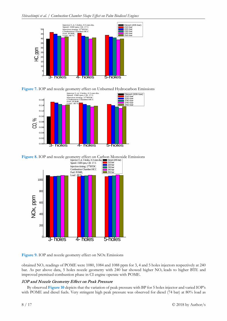
IOP and Nozzle Geometry Effect on HC and CO Emissions From the Figures 7 and 8 showed the effect of various IOP and nozzle geometries on HC and CO emissions
with BP for POME and diesel fuels. The standard diesel has showed HC, CO emissions were 36 ppm and 0.1% respectively. There was decreasing trend of emissions in both HC and CO emissions by increase in both injection pressure and number of nozzle holes operate with POME biodiesel in engine. The minimum emissions were obtained up to 240 bar only with 5 holes nozzle due to improved combustion in engine operated with POME fuel leads to lower emissions in both HC and CO. At same time both pollutants has been increased trend for POME at 25 MPa IOP in diesel engine due to lower BTE. The reason for reducing in both pollutants in engine operates with POME at 240 bar and 5 holes was due to lower ignition delay and diffused combustion phase. The HC results for POME were obtained 41, 40 and 39 ppm for 3, 4 and 5 holes injectors respectively at 240 bar. Similarly CO results for POME were obtained 0.14, 0.135 and 0.13% for 3, 4 and 5 holes injectors respectively at 240 bar. The configurations of 5 holes injector and 240 bar was depicted to reduced in both emissions due to proper combustion and reduced viscosity of POME fuel at higher injection pressure.
IOP and Nozzle Geometry Effect on NOx Emissions As observed from Figure 9 showed the variation of NOx with BP for both varied IOP and nozzle holes
operated with POME and diesel fuels. The oxides of nitrogen emissions were increased due to peak temperature generated in combustion chamber. The standard mineral fuel has showed 1090 ppm NOx due to enhanced pre combustion phase in engine. Usually NOx emission was increases for POME operation in engine as increase in both IOP and number of injector holes due to proper combustion. The higher NOx obtained in engine operated with POME at 240 bar with 5 holes due to raised peak temperature leads to reduced viscosity of POME. The
3- holes 4- holes 5-holes0
10
20
30
40
50
60
Injector:3 ,4, 5 holes, 0.3 mm dia.Speed: 1500 rpm, CR: 17.5Injection timing: 270BTDCCombustion Chamber:HCCFuel: POME, Load : 80 %
Smok
e O
pacit
y, H
SU
Diesel(205 bar) 210 bar 220 bar 230 bar 240 bar 250 bar
Figure 6. IOP and nozzle geometry effect on Smoke opacity
Shivashimpi et al. / Combustion Chamber Shape Effect on Palm Biodiesel Engines
8 / 17 © 2018 by Author/s
obtained NOx readings of POME were 1080, 1084 and 1088 ppm for 3, 4 and 5 holes injectors respectively at 240 bar. As per above data, 5 holes nozzle geometry with 240 bar showed higher NOx leads to higher BTE and improved premixed combustion phase in CI engine operate with POME.
IOP and Nozzle Geometry Effect on Peak Pressure By observed Figure 10 depicts that the variation of peak pressure with BP for 5 holes injector and varied IOP’s
with POME and diesel fuels. Very stringent high peak pressure was observed for diesel (74 bar) at 80% load as
3- holes 4- holes 5-holes0
5
10
15
20
25
30
35
40
45
50
Injector:3 ,4, 5 holes, 0.3 mm dia.Speed: 1500 rpm, CR: 17.5Injection timing: 270BTDCCombustion Chamber:HCCFuel: POME, Load : 80 %
HC, p
pm
Diesel (205 bar) 210 bar 220 bar 230 bar 240 bar 250 bar
Figure 7. IOP and nozzle geometry effect on Unburned Hydrocarbon Emissions
3- holes 4- holes 5-holes0.00
0.02
0.04
0.06
0.08
0.10
0.12
0.14
0.16
Injector:3 ,4, 5 holes, 0.3 mm dia.Speed: 1500 rpm, CR: 17.5Injection timing: 270BTDCCombustion Chamber:HCCFuel: POME, Load : 80 %
CO, %
Diesel (205 bar) 210 bar 220 bar 230 bar 240 bar 250 bar
Figure 8. IOP and nozzle geometry effect on Carbon Monoxide Emissions
3- holes 4- holes 5-holes0
200
400
600
800
1000
Injector:3 ,4, 5 holes, 0.3 mm dia.Speed: 1500 rpm, CR: 17.5Injection timing: 270BTDCCombustion Chamber:HCCFuel: POME, Load : 80 %
NOx,
ppm
Diesel (205 bar) 210 bar 220 bar 230 bar 240 bar 250 bar
Figure 9. IOP and nozzle geometry effect on NOx Emissions

European Journal of Sustainable Development Research, 2(3), 35
© 2018 by Author/s 9 / 17
compared to POME operation due to high energy content in diesel fuel. The POME was showing increased trend in peak pressure as increase in injection pressure with 5 holes injector due to improved atomization of fuel characteristics at higher pressure of fuel. The peak pressure was reducing trend beyond the 240 bar in engine for POME due to negating effect of the engine. By experimental records for POME results obtained in engine were 71, 72, 74 and 73 bar for 220,230,240 and 250 bar respectively for 5 holes injector. The 5 holes injector has showed with higher peak pressure in engine operated with POME fuel due to lower ignition delay, higher adiabatic temperature and improved burning effect at 240 bar.
IOP and Nozzle Geometry Effect on Ignition Delay Figure 11 showed the variation of ID with BP for various IOP and 5 holes nozzle operated with POME and
diesel fuels. The ID has been calculated based on injection timing at static condition. Due to proper combustion for 5 holes nozzle geometry, The mineral diesel has showed the lower ID (9.8 °CA) at 80% load than POME for all IOP due to higher calorific value of diesel fuel. The ID was longer for POME than the diesel due to presence of higher viscosity. POME was showing the decreased trend of ID when increased in IOP with 5 holes nozzle due to combustion rate was fast at higher in engine injection pressure. The ID was increased trend beyond the 240 bar
0.00 1.04 2.08 3.12 4.16 5.2068
70
72
74
76
78
80
82
84
220 bar 230 bar 250 bar Diesel 205 bar 240 bar
Speed: 1500 rpmCR: 17.5Injection Timing: 27oBTDCCR: 17.5, Injector: 5 hole, 0.3 mm dia.Fuel: POME
Peak
Pre
ssur
e, ba
r
Brake Power, kW
Figure 10. IOP and nozzle geometry effect on Peak Pressure
0.00 1.04 2.08 3.12 4.16 5.208.0
8.5
9.0
9.5
10.0
10.5
11.0
11.5
12.0Speed: 1500 rpmCR: 17.5Injection Timing: 27oBTDCCR: 17.5, Injector: 5 hole, 0.3 mm dia.Fuel: POME
Igni
tion
Delay
, o CA
Brake Power, kW
220 bar 230 bar 250 bar Diesel 205 bar 240 bar
Figure 11. IOP and nozzle geometry effect on Ignition Delay period

Shivashimpi et al. / Combustion Chamber Shape Effect on Palm Biodiesel Engines
10 / 17 © 2018 by Author/s
in engine for POME due to negating effect of the engine. By experimental report for POME results obtained in engine were 10.1, 10, 9.8 and 9.9 °CA for 220,230,240 and 250 bar respectively for 5 holes injector. The 5 holes injector has showed with lower ID in engine operated with POME fuel due to improved burning rate of POME at 240 bar.
IOP and Nozzle Geometry Effect on Combustion Duration By the observed Figure 12 showed that the variation of combustion duration with BP for all IOP and 5 holes
nozzle with diesel and POME. The CD was calculated with respect to start of combustion and heat release rate of 90%. The mineral diesel was showing the CD as 38 °CA, it is lower than POME due to lower viscosity and higher diffused combustion could be the reason. CD was higher with POME than the diesel due to higher viscosity and improper mixing strength. The CD was decreases as increased in injection pressure when operated with POME as a fuel in combustion chamber in engine due to reduced in ignition lag, high peak pressure and faster combustion process in the combustion chamber with 5 holes nozzle. The CD was showing higher duration for lower IOP operated with POME due to longer diffusion combustion phase. But CD was increased trend beyond the 240 bar pressure due to negating effect of engine. By experimental report for POME results obtained in engine were 43, 42, 40 and 41 °CA for 220,230,240 and 250 bar respectively for 5 holes injector. The 5 holes injector has showed with lower CD in engine operated with POME fuel due to optimum diffusion combustion phase in POME at 240 bar.
Combustion Chamber Shape Optimization for POME
The IOP 240 bar and 5 holes nozzle geometry were optimized for POME fuel in first phase of research work under diesel engine conditions of 27°BTDC and 80% load. The combustion has not only improved by modification of injection strategies for POME operation in engine. The combustion parameters are also greatly influence on the modification of combustion shape as well as injection strategies in diesel engine operated with POME. Hence there are various combustion chambers shapes such as Hemispherical (HCC), Cylindrical (CCC) Toroidal (TCC) and Toroidal Re-entrant combustion chamber (TRCC) shapes selected for the study in diesel engine fuelled with POME. The experiments were carried on the diesel engine operated with POME as a fuel with HCC, CCC, TCC and TRCC shapes under the engine conditions of 27°BTDC, 240 bar, 5 hole geometry and 80% load. The experiments were carried on the diesel engine operated with diesel as a fuel with HCC shape under manufacturer engine conditions of 23°BTDC, 205 bar, 3 holes geometry and 80% load. The comparisons has made with respect to standard HCC shape of engine keeping the CR same in all the shapes. The experiments were carried out for diesel engine and analyzed performance, combustion and emission characteristics for all combustion chamber shapes and also found efficient combustion shape for POME in engine under the above optimized parameters. The results and discussions of POME operated CCS analyzed with keeping constant parameters were 27°BTDC, 240 bar, 5 hole geometry and 80% load. Similarly, for diesel operated HCC shape analyzed with keeping constant parameters were 23°BTDC, 205 bar, 3 holes geometry and 80% load.
0.00 1.04 2.08 3.12 4.16 5.2039
40
41
42
43
44
45
46
47
48
49
50
220 bar 230 bar 250 bar Diesel 205 bar 240 bar
Speed: 1500 rpmCR: 17.5Injection Timing: 27oBTDCCR: 17.5, Injector: 5 hole, 0.3 mm dia.Fuel: POME
Com
busti
on D
urati
on, o CA
Brake Power, kW
Figure 12. IOP and nozzle geometry effect on Combustion Duration

European Journal of Sustainable Development Research, 2(3), 35
© 2018 by Author/s 11 / 17
Combustion Chamber Shape Effect on Brake Thermal Efficiency Figure 13 presents the variation of BTE with BP for various combustion chambers shapes (CCS) operated
with POME and diesel fuels. The diesel fuel operated HCC shape was showing higher BTE (31.25%) as compared with POME fuel operated combustion chamber shapes. This difference of BTE was due to variations of fuel properties such as viscosity, calorific value, rating numbers and flash point etc. The BTE has increases as increase in BP for the all shapes The POME operated TRCC shape showed increased thermal efficiency than other CCS. The flame prevention from spreading on the squish region of chamber may result into proper formation of mixture of air with POME leads to enhance the flame propagation. Hence BTE has been improved in diesel engine for TRCC shape. The POME operated HCC and CCC shape were undergone unnecessary compression work by initiating the combustion process before TDC, hence BTE of these shapes decline in nature in engine as compared to TRCC shape. The ignition delay and combustion duration were higher in POME operated HCC and CCC shapes, it leads to decreased in BTE might be the reason. However, both POME operated with TCC shape and TRCC shape have given marginally same BTE. Use of TCC and TRCC shapes witnessed in enhanced combustion during the expansion stroke. The POME operated BTE results were obtained as 28.5%, 28.75%, 29.1% and 29.3% for HCC, CCC, TCC and TRCC respectively in diesel engine under the engine conditions of 27°BTDC, 240 bar, 5 hole geometry and 80% load.
Combustion Chamber Configuration Effect on Smoke Opacity Figure 14 presents smoke opacity variation with BP for different CCS operated with POME and diesel fuels.
The diesel operated HCC shape in engine shown lower smoke level (46 HSU) as compared with POME operated combustion chamber shapes. It may be caused by improper air-fuel mixing leading to reduced oxidation during combustion of POME. The POME operated TRCC shape lower smoke intensity in engine as compared with remaining CCS due to improved air-fuel mixing leads to better turbulence occurred in combustion core with
0.00 1.04 2.08 3.12 4.16 5.200
5
10
15
20
25
30
35 Diesel (HCC) POME (HCC) POME (CCC) POME (TCC) POME (TRCC)
Speed: 1500 RPM, CR: 17.5Injection timing: 27 o bTDCInjection pressure: 240 barInjector: 5 holes, Diameter: 0.3 mmFuel: Palm Oil Methyl Ester (POME)
Brake
therma
l effici
ency, %
Brake power, kW
Figure 13. Combustion chamber shape effect on Brake Thermal Efficiency
0.00 1.04 2.08 3.12 4.16 5.200
10
20
30
40
50
60
70
80 Speed: 1500 RPM, CR: 17.5Injection timing: 27 obTDCInjection pressure: 240 barInjector: 5 holes, 0.3 mmFuel: Palm Oil Methyl Ester (POME)
Diesel (HCC) POME (HCC) POME (CCC)POME (TCC) POME (TRCC)
Smok
e opa
city,
HSU
Brake Power, kW
Figure 14. Combustion chamber configuration effect on smoke opacity

Shivashimpi et al. / Combustion Chamber Shape Effect on Palm Biodiesel Engines
12 / 17 © 2018 by Author/s
reduced soot particles. The POME operated TCC shape has given similar results as that of TRCC shape in engine. The POME operated TRCC and TCC shapes were produced enhanced turbulent kinetic energy in their combustion chamber shapes leads to lower the smoke level as compared to POME operated HCC and CCC shapes in engine. Smoke levels were observed that, 49 HSU, 48 HSU, 47 HSU and 47 HSU for HCC, CCC, TCC and TRCC respectively for diesel engine.
Combustion Chamber Shape Effect on HC and CO Emissions Figures 15 and 16 depicted that the variation of HC and CO emissions with BP for various combustion
chamber shapes as operated with POME and diesel fuels. The diesel operated HCC shape shown in engine lower emissions of HC (36 ppm) and CO (0.1%) as compared with POME operated combustion chamber shapes due to difference in fuel properties. Minimum and lower M.E.P. was responsible for rise of HC and CO pollutants with POME operation in engine. By experimentally observed that POME operated TRCC shape resulted very low HC and CO emissions as compared to other POME operated shapes. The POME operated TRCC shape was ensured proper combustion of POME due to improved swirl and squish motion resulting in increased BTE. The TCC shape also resulted into similar trends with that of TRCC with POME operation in engine. For POME operation of engine, HCC/CCC may not be resulted in correct air-fuel mixing associated with unusual swirl existence with high viscous fuel leading to partial combustion. The POME operated HC levels were 43 ppm, 41ppm, 39 ppm and 38ppm for HCC, CCC, TCC and TRCC shapes respectively in diesel engine. Similarly for POME operation of CO emissions were 0.15%, 0.145%, 0.142% and 0.14% ppm, for HCC, CCC, TCC and TRCC shapes respectively in diesel engine.
Combustion Chamber Shape Effect on NOx Emission Figures 17 depicted that the variation of NOx emissions with BP for various combustion chamber shapes as
operated with POME and diesel fuels. The diesel operated HCC shape given highest NOx (1090ppm) emissions as compared to other CCS due to attainment of higher peak temperature in combustion chamber shape. The POME operated combustion chamber shapes showed lower NOx emissions due to improper combustion process during premixed combustion phase and higher viscosity of POME may be the reason. The POME operation with TRCC shape shown higher NOx emissions due to better utilization of oxygen during combustion process. Hence improved swirl and turbulence characteristics were generated in TRCC shape as compared to HCC/CCC/ TCC shapes when POME operated in engine. The POME operated NOx levels were found to 1070, 1075, 1081 and 1085 ppm for HCC, CCC, TCC and TRCC shapes respectively in diesel engine.
0.00 1.04 2.08 3.12 4.16 5.2010
20
30
40
50
60
70
80
Diesel (HCC) POME (HCC) POME (CCC) POME (TCC) POME (TRCC)
Speed: 1500 RPM, CR: 17.5Injection timing: 27 o bTDCInjection pressure: 240 barInjector: 5 holes, Diameter: 0.3 mmFuel: Palm Oil Methyl Ester (POME)
Hydr
ocar
bon,
ppm
Brake power, kW
Figure 15. Combustion chamber shape effect on HC Emission
0.00 1.04 2.08 3.12 4.16 5.200.040.080.120.160.200.240.280.320.360.40
Diesel (HCC) POME (HCC) POME (CCC) POME (TCC) POME (TRCC)
Speed: 1500 RPM, CR: 17.5Injection timing: 27 o bTDCInjection pressure: 240 barInjector: 6 holes, 0.3 mmFuel: Palm Oil Methyl Ester (POME)
Carb
on m
onox
ide,
%
Brake power, kW
Figure 16. Combustion chamber shape effect on CO Emission

European Journal of Sustainable Development Research, 2(3), 35
© 2018 by Author/s 13 / 17
Combustion Chamber Shape Effect on Peak Pressure Figure 18 shows peak pressure variation with brake power on diesel engine operated with POME for various
combustion chamber configurations selected. The diesel operated with HCC shape has given peak pressure of 74 bar, it lower than remaining CCS due to high content energy level of diesel fuel. POME pressure rise in the combustion chamber less than diesel due to improper combustion. However, Lower calorific value and incomplete combustion caused by the large and heavier molecular weight fatty acids of POME may be responsible for these trends of the result. The POME operated TRCC sahpe results into higher peak pressure as it provides swirl associated with turbulence this leads to improved air-fuel mixture during combustion process in engine. However, POME operated TCC shows marginally similar trends as that of TRCC followed by CCC and HCC shapes. The POME operated PP levels were found to be 70, 71, 72 and 72 bar for HCC, CCC, TCC and TRCC shapes respectively in diesel engine.
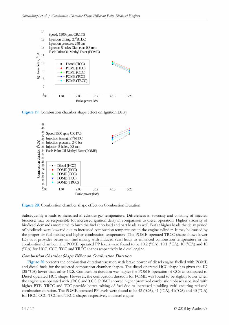
Combustion Chamber Shape Effect on Ignition Delay Figure 19 depicts that the variation of ID with BP for various combustion chamber shapes operated with
POME and diesel fuels. The diesel operated HCC shape has shown the ID 9.9 °CA lower than other CCS due to variation of fuel properties. As the engine power output increased the amount of fuel consumed also increased.
0.00 1.04 2.08 3.12 4.16 5.200
200
400
600
800
1000
1200
1400
1600
Diesel (HCC) POME (HCC) POME (CCC) POME (TCC) POME (TRCC)
Speed: 1500 RPM, CR: 17.5Injection timing: 27 o bTDCInjection pressure: 240 barInjector: 5 holes, 0.3 mmFuel: Palm Oil Methyl Ester (POME)
Nitri
c oxi
de, p
pm
Brake power, kW
Figure 17. Combustion chamber shape effect on NOx Emission
0.00 1.04 2.08 3.12 4.16 5.2050
55
60
65
70
75
80
85
90
Diesel (HCC) POME (HCC) POME (CCC) POME (TCC) POME (TRCC)
Speed: 1500 rpm, CR:17.5Injection timing: 270BTDCInjection pressure: 240 barInjector: 5 holes, 0.3 mmFuel: Palm Oil Methyl Ester (POME)
Peak
pre
ssur
e, ba
r
Brake power, kW
Figure 18. Effect of combustion chamber shape on Peak Pressure
Shivashimpi et al. / Combustion Chamber Shape Effect on Palm Biodiesel Engines
14 / 17 © 2018 by Author/s
Subsequently it leads to increased in-cylinder gas temperature. Differences in viscosity and volatility of injected biodiesel may be responsible for increased ignition delay in comparison to diesel operation. Higher viscosity of biodiesel demands more time to burn the fuel at no load and part loads as well. But at higher loads the delay period of biodiesels were lowered due to increased combustion temperatures in the engine cylinder. It may be caused by the proper air-fuel mixing and higher combustion temperature. The POME operated TRCC shape shows lower IDs as it provides better air- fuel mixing with induced swirl leads to enhanced combustion temperature in the combustion chamber. The POME operated PP levels were found to be 10.2 (°CA), 10.1 (°CA), 10 (°CA) and 10 (°CA) for HCC, CCC, TCC and TRCC shapes respectively in diesel engine.
Combustion Chamber Shape Effect on Combustion Duration Figure 20 presents the combustion duration variation with brake power of diesel engine fuelled with POME
and diesel fuels for the selected combustion chamber shapes. The diesel operated HCC shape has given the ID (38 °CA) lower than other CCS. Combustion duration was higher for POME operation of CCS as compared to Diesel operated HCC shape. However, the combustion duration for POME was found to be slightly lower when the engine was operated with TRCC and TCC. POME showed higher premixed combustion phase associated with higher BTE. TRCC and TCC provide better mixing of fuel due to increased tumbling swirl ensuring reduced combustion duration. The POME operated PP levels were found to be 42 (°CA), 41 (°CA), 41(°CA) and 40 (°CA) for HCC, CCC, TCC and TRCC shapes respectively in diesel engine.
0.00 1.04 2.08 3.12 4.16 5.206
7
8
9
10
11
12
13
14
Diesel (HCC) POME (HCC) POME (CCC) POME (TCC) POME (TRCC)
Speed: 1500 rpm, CR:17.5Injection timing: 270BTDCInjection pressure: 240 barInjector: 5 holes Diameter: 0.3 mmFuel: Palm Oil Methyl Ester (POME)
Igni
tion
delay
, 0 CA
Brake power, kW
Figure 19. Combustion chamber shape effect on Ignition Delay
0.00 1.04 2.08 3.12 4.16 5.20141618202224262830323436384042444648
Diesel (HCC) POME (HCC) POME (CCC) POME (TCC) POME (TRCC)
Speed:1500 rpm, CR:17.5Injection timing: 270bTDCInjection pressure: 240 barInjector: 5 holes, 0.3 mmFuel: Palm Oil Methyl Ester (POME)
Com
busti
on d
urati
on (0 CA
)
Brake power (kW)
Figure 20. Combustion chamber shape effect on Combustion Duration
European Journal of Sustainable Development Research, 2(3), 35
© 2018 by Author/s 15 / 17
CONCLUSIONS
From the exhaustive experimental tests conducted with POME powered diesel engine, the following final conclusions could be enlisted:
• The maximum BTE and lower emissions were obtained at 240 bar, 5 holes nozzle geometry at IT of 27°BTDC, when CI engine was operated with POME as a fuel.
• The maximum BTE and lower emissions were reported for Toroidal re-entrant combustion chamber shape, when diesel engine was operated with POME as a fuel at IT of 27°BTDC, 240 bar, 5 holes nozzle geometry.
On overall, the maximum BTE and lower emissions were reported at IT of 27°BTDC, IOP of 240 bar and 5 holes nozzle geometry with Toroidal re-entrant combustion chamber shape, When POME as alternative fuel used in CI engine. By this experiment, there was enhanced mixing of air and POME in Toroidal re-entrant combustion chamber shape to meet the global requirement of pollution norms and also save the global requirement of fuel for transportation.
REFERENCES
Abhishek, S. and Murugan, S. (2013). Investigation on the behavior of a DI diesel engine fuelled with Jatropha Methyl Ester (JME) and Tyre Pyrolysis Oil (TPO) blends. Fuel, 108, 699–708. https://doi.org/10.1016/j.fuel.2012.12.042
Atadashi, I. M., Aroua, M. K. and Abdul Azizm A. (2010). High quality biodiesel and its diesel engine application: A review. Journal of Renewable and Sustainable Energy Reviews, 14(7), 1999-2008. https://doi.org/10.1016/j.rser.2010.03.020
Atmanli, A., Ileri, E. and Yuksel, B. (2014). Experimental investigation of engine performance and exhaust emissions of a diesel engine fueled with diesel-n-butanol vegetable oil blends. Energy Convers Manage, 81, 312–21. https://doi.org/10.1016/j.enconman.2014.02.049
Aydın, H. and Ilkılıc, C. (2015). Analysis of combustion, performance and emission characteristics of a diesel engine using low sulfur tire fuel. Fuel, 143, 373-82. https://doi.org/10.1016/j.fuel.2014.11.075
Balat, M. and Balat, H. (2008). A critical review of bio-diesel as a vehicular fuel. Energy Convers Manage, 49, 2727–41. https://doi.org/10.1016/j.enconman.2008.03.016
Banapurmath, N. R., Hosmath, R. S. and Tewari, P. G. (2008). Performance and Emissions Characteristics of a DI Compression Ignition Engine Operated OnHonge, Jatropha and Sesame Oil Methyl Esters. Renewable Energy, 33, 1982-1988. https://doi.org/10.1016/j.renene.2007.11.012
Banapurmath, N. R., Tewari, P. G. and Vinodkumar, V. (2009). Combustion and emission characteristics of a direct injection CI engine when operated on Marotti oil methyl ester and blends of Marotti oil methyl ester and diesel. International Journal of Sustainable Engineering, 2, 192 – 200. https://doi.org/10.1080/19397030903089983
Banapurmath, N. R., Tewari, P. G., Gaitonde, V. N. (2012). Experimental investigations on performance and emission characteristics of Honge oil biodiesel (HOME) operated compression ignition engine. Renewable Energy, 48, 193-201. https://doi.org/10.1016/j.renene.2012.04.010
Banapurmath, N. R., Chavan, A. S., Bansode, S. B., Sankalp, P., Naveen, G., Sanketh, T., Keerthi, K. N. and Tandale, M. S. (2015). Effect of Combustion Chamber Shapes on the Performance of Mahua and Neem Biodiesel Operated Diesel Engines. Journal of Petroleum & Environmental Engineering. https://doi.org/10.4172/2157-7463.1000230
Bari, S., Yu, C. W., Lim, T. H. (2004). Effect of fuel injection timing with waste cooking oil as a fuel in direct injection diesel engine. Proc. Instn. Mech. Engrs. IMechE, Part D, Journal of Automobile Engineering, 218, 93-104. https://doi.org/10.1243/095440704322829209
Dixit, S. and Rehman, A. (2012). Linseed oil as a potential resource for bio-diesel: a review. Renew Sustain Energy Rev, 16, 4415–21. https://doi.org/10.1016/j.rser.2012.04.042
Gautam, A. and Agarwal, A. K. (2013). Experimental investigations of comparative performance, emission and combustion characteristics of a cotton seed biodiesel-fueled four-stroke locomotive diesel engine. Int J Engine Res, 14(4), 354–72. https://doi.org/10.1177/1468087412458215
Jaichandar, S. and Annamalai, K. (2012). Effects of open combustion chamber geometries on the performance of pongamia biodiesel in a DI diesel engine. Fuel, 98, 272–279. https://doi.org/10.1016/j.fuel.2012.04.004
Jaichandar, S., Kumar, P. S. and Annamalai, K. (2012). Combined effect of injection timing and combustion chamber geometry on the performance of a biodiesel fueled diesel engine. Energy, 47(1), 388-394. https://doi.org/10.1016/j.energy.2012.09.059
Shivashimpi et al. / Combustion Chamber Shape Effect on Palm Biodiesel Engines
16 / 17 © 2018 by Author/s
Jaichandar, S. and Annamalai, K. (2013). Combined Impact of Injection Pressure and Combustion Chamber Geometry on the performance of a biodiesel fueled diesel engine. Energy, 55, 330-339. https://doi.org/10.1016/j.energy.2013.04.019
Hountalas, D. T., Kouremenos, D. A., Binder, K. B., Raab, A. and Schnabel, M. H. (2001). Using advanced Injection timing and EGR to Improve DI engine efficiency at Acceptable NO and Soot levels. Society of Automotive Engineers, Paper No.: 2001-01-0199.
Kannan, D., Pachamuthu, S., Nurun, N. M., Hustad, J. E. and Lovas, T. (2012). Theoretical and experimental investigation of diesel engine performance, combustion and emissions analysis fuelled with the blends of ethanol, diesel and Jatropha methyl ester. Energy Convers Manage, 53, 322–31. https://doi.org/10.1016/j.enconman.2011.09.010
Karra, P. K. and Kong, S.-C. (2010). Experimental study on effects of nozzle holes geometry on achieving low diesel engine emissions. Journal of Engineering for Gas Turbines and Power, 132(2), 022802. https://doi.org/10.1115/1.3124791
Khandal, S. V., Banapurmath, N. R., Gaitonde, V. N. and Hosmath, R. S. (2015). Effect of Number of Injector Nozzle Holes on the Performance, Emission and Combustion Characteristics of Honge Oil Biodiesel (HOME) Operated DI Compression Ignition Engine. Journal of Petroleum & Environmental Engineering.
Kumar, V. (2017), Experimental investigation of piston bowl geometry effects on performance andemissions characteristics of diesel engine at variable injection pressure and timings. International Journal of Ambient Energy, ISSN: 0143-0750 (Print) 2162-8246.
Labeckas, G. and Slavinskas, S. (2006). The effect of rapeseed oil methyl ester on direct injection diesel engine performance and exhaust emissions. Energy Convers Manage, 47, 1954–67. https://doi.org/10.1016/j.enconman.2005.09.003
Lahane, S. and Subramanian, K. A. (2014). Impact of nozzle holes configuration on fuel spray, wall impingement and NOx emission of a diesel engine for biodiesel–diesel blend (B20). Applied Thermal Engineering, 64(1), 307-314. https://doi.org/10.1016/j.applthermaleng.2013.12.048
Mamilla, V. R., Mallikarjun, M. V. and Rao, G. L. N. (2013). Effect of Combustion Chamber Design on a DI Diesel Engine Fuelled with Jatropha Methyl Esters Blends with Diesel. Procedia Engineering, 64, 479-490. https://doi.org/10.1016/j.proeng.2013.09.122
Mani, M., Nagarajan, G. and Sampath, S. (2011). Characterization and effect of using waste plastic oil and diesel fuel blends in compression ignition engine. Energy, 36, 212-219. https://doi.org/10.1016/j.energy.2010.10.049
Murugesan, A., Umarani, C., Subramanian, R. and Nedunchezhian, N. (2009). Bio-diesel as an alternative fuel for diesel engines-A Review. Renewable and Sustainable Energy Reviews, 13(3), 653-662. https://doi.org/10.1016/j.rser.2007.10.007
Naik, S. N., Vaibhav, V., Goud Prashant, K., Rout, A. and Dalai, K. (2010). Production of first and second generation biofuels: A comprehensive review. Renewable and sustainable energy reviews, 14, 578-597. https://doi.org/10.1016/j.rser.2009.10.003
Paul, T. and Williams. (2013) Pyrolysis of waste tyres: A review. Waste Management, 33, 1714-1728. https://doi.org/10.1016/j.wasman.2013.05.003
Pratoomyod, J. and Laohalidanond, K. (2013). Performance and Emission Evaluation of Blends of Diesel fuel with Waste Plastic Oil in a Diesel Engine. IJESIT, 2(2).
Rajashekhar, C. R., Tumkur, K. C., Chebbiyyan, U. and Rajagopal, H. R. (2012). Studies on effects of combustion chamber geometry and injection pressure on biodiesel combustion. Transactions of the Canadian Society for Mechanical Engineering, 36(4), 429-438. https://doi.org/10.1139/tcsme-2012-0030
Raouf, M. and Peng, Z. (2013). CFD Investigation of the Effects of Re-Entrant Combustion Chamber Geometry in a HSDI Diesel Engine. World Academy of Science, Engineering and Technology. International Journal of Mechanical, Aerospace, Industrial, Mechatronic and Manufacturing Engineering, 7(4), 770-780.
Rosli, A. B., Semin, A. and Rahim, I. (2008). Fuel injection pressure effect on performance of direct injection diesel engines based on experiment. American Journal of Applied Sciences, 5, 197- 202. https://doi.org/10.3844/ajassp.2008.197.202
Roy, M. M. (2009). Effect of fuel injection timing and injection pressure on combustion and odorous emissions in DI diesel engine. Journal of Energy Resources Technology, ASME Transactions, 131, 1-8. https://doi.org/10.1115/1.3185346
Sharma. A. and Murugan, S. (2015). Combustion, performance and emission characteristics of a DI diesel engine fuelled with non-petroleum fuel: A study on the role of fuel injection timing. Journal of the Energy Institute, 88, 364-75. https://doi.org/10.1016/j.joei.2014.11.006
Shivashimpi, M. M., Alur, S. A., Topannavar, S. N. and Dodamani, B. M. (2017). Combined Effect of Cylindrical Combustion Chamber Shape And Nozzle Geometry On The Performance And Emission Characteristics of

European Journal of Sustainable Development Research, 2(3), 35
© 2018 by Author/s 17 / 17
C.I. Engine Operated On Pongamia. Proceedings of the 1st International and 18th national ISME Conference on Mechanical Engineering: Enabling Sustainable Development, NIT Warangal, India February 23rd – 25th, pp-113.
Shivashimpi, M. M., Alur, S. A. and Topannavar, S. N. (2016). Effect of Cylindrical combustion chamber shape on the performance and Emission Characteristics of C.I. Engine Operated on Pongamia. Journal of Adnances in science and Technology, 12(25) (Special Issue), December, ISSN 2230-9659.
Srivastava, P. K. and Verma, M. (2008). Methyl ester of karanja oil as alternative renewable source energy. Fuel, 87, 1673–7. https://doi.org/10.1016/j.fuel.2007.08.018
Sukumar, P., Jegan, R, Balasubbramanian, K. and Nagarajan, G. (2009). Effect of injection pressure on performance, emission and combustion characteristics of high linolenic linseed oil methyl ester in a DI Diesel engine. Renewable Energy, 34, 1227-33. https://doi.org/10.1016/j.renene.2008.10.001
Suresh, G., Kamath, H. C. and Banapurmath, N. R. (2013). Effect of Injection timing, Injector opening pressure and Nozzle geometry on the performance of Cotton seed oil methyl ester fuelled diesel engine. International Journal of Sustainable Engineering, Francis and Taylor Publications, 7, 82-92.
Tao, F., Liu, Y., Rempel Ewert, B. H., Foster, D. E., Reitz, R. D., Choi, D. and Miles, P. C. (2005). Modelling the effect of EGR and retarded injection on soot formation in a high-speed diesel injection (HSDI) diesel engine using a multi-step phenomenological soot model. Society of Automotive Engineers, Paper No.: 2005 -01-0121.
Wategave, S. P., Sawant, M. S., Tandale, M. S., Suresh, G., Yaliwalc, V. S., Banapurmath, N. R. and Tewari, P. G. (2014). Effect of injection timing, injector opening pressure and nozzle geometry on the performance of a compression ignition engine operated on non-edible oil methyl esters from different sources. International Journal of Sustainable Engineering, 7(1), 71–81. https://doi.org/10.1080/19397038.2013.777134
Yaliwal, V. S., Banapurmath, N. R., Gireesh, N. M., Hosmath, R. S., Donateo, T. and Tewari, P. G. (2016). Effect of nozzle and combustion chamber geometry on the performance of a diesel engine operated on dual fuel mode using renewable fuels. Renewable Energy, 93, 483-501. https://doi.org/10.1016/j.renene.2016.03.020