vented heater service manual · 1-5 combustion chamber the combustion chamber consists of two main...
TRANSCRIPT
VENTED HEATER SERVICE MANUAL
Laser 300 (TypeA)
Laser 530 (TypeA)
Laser 560 (TypeA)
Laser 730 (TypeA)
L A S E R H E A T I N G S Y S T E M S
Table of Contents
Description
1-1 Introduction1-2 Physical Specifications1-3 Description of Functions1-4 Description1-5 Combustion Chamber1-6 Burne1-7 Burner Ring Assembly1-8 Burner Mat / Coating1-9 Flame Rod Sensor1-10 Igniter1-11 Flue Pipe1-12 Blower Motor Assembly1-13 Air Circulation Fan1-14 External Fuel Tank1-15 Fuel Pump1-16 Control Circuit Board1-17 Room Temperature Sensor1-18 Fuel Sump (Fuel Constant Level Valve)1-19 Cloth Covered Exhaust Pipe1-20 Air Circulation Fan Filter (Cover)1-21 Fuse1-22 Overheat Protector Switch1-23 Pressure Relief Plate1-24 Combustion System1-25 Forced Flue Venting System
1-26 Fuel Delivery System1-27 Electrical System1-28 Safety Mechanisms1-29 Power Failure Recovery System1-30 Operation Recovery1-31 Reigniting Operation1-32 Error Codes History1-33 Igniting Failure Error Lock1-34 Burner Thermistor Normal Detecting
Temperatures1-35 Power Failure Recovery System1-36 Backup Life1-37 Deleting The Error Code History1-38 Detection of Abnormal Electrical
Frequency Condition1-39 Power Button Malfunction1-40 Low Voltage Detection1-41 Forced Flame Detection1-42 Manual Ignitor Cleaning System1-43 Automatic Ignitor Cleaning System1-44 Manual Combustion Operation Mode1-45 High Altitude Setting Mode1-46 Combustion Cleaning Mode1-47 Flow Volume Setting Mode for The Fuel
Pump
Page 1-8
Section 1
Maintenance
2-1 Introductlon 2-2 Routine maintenance
Page 9-10
Section 2
Service
3-1 3-2 3-3
3-4
IntroductionCleaning The Heat Exchanger and Burner Removal of Water Deposits and Contaminants From Fuel Sump and Fuel
LinesCleaning The Fuel Filter or Water Block Filter
3-5 Error Message3-6 Inspect Intake/Exhaust Air Lines3-7 Verify Igniter Operation3-8 Clean Fuel Inlet Strainer3-9 Replacement of Fuses3-10 Fuel Contamination3-11 Cleaning Blower Motor
Page 11-17
Section 3
Trouble Shooting
4-1 Resistor/Capacitor Value4-2 Control Circuit Board Time Chart
4-3 Parts Description
Page 18-45
Section 4
S E R V I C E M A N U A L 1
L A S E R H E A T I N G S Y S T E M S
1-1 IntroductionThe Laser Heating System is a completely new type of
sophisticated and fuel-efficient vented system featuring
its own housing, combustion and air circulation systems
and a micro computer control system.
In addition to superior design and technology, rigorous
testing for quality and safety have made the Laser
Heating System unmatched for efficiency, convenience,
economy and flexibility. Plus, the Laser is easy to maintain and required minimal service.
The following section outlines the Laser Heater and its
various components
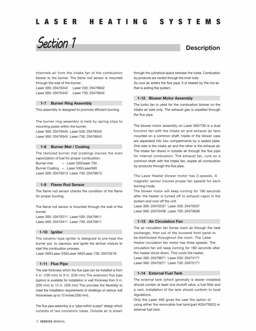
1-2 Physical Specifications
W × D × H (inches) Weight Flue PipeHole
Laser 300 17-3/8” × 21-3/4” × 15-1/8”(440 × 555 × 385 mm)
31 lbs.(14kg)
2-3/4to 3”
diameter(7.0 -
7.5 cm)
Laser 530 19-5/8” × 23-5/8” × 16-1/2”(496 × 600 × 418 mm)
38 lbs.(17kg)
Laser 560 24-3/8” × 26-3/4” × 16”(620 × 680 × 405 mm)
60 lbs.(27kg)
Laser 730/Laser 730AT
30” × 27-1/2” × 16-3/4”(760 × 700 × 427 mm)
75 lbs.(34kg)
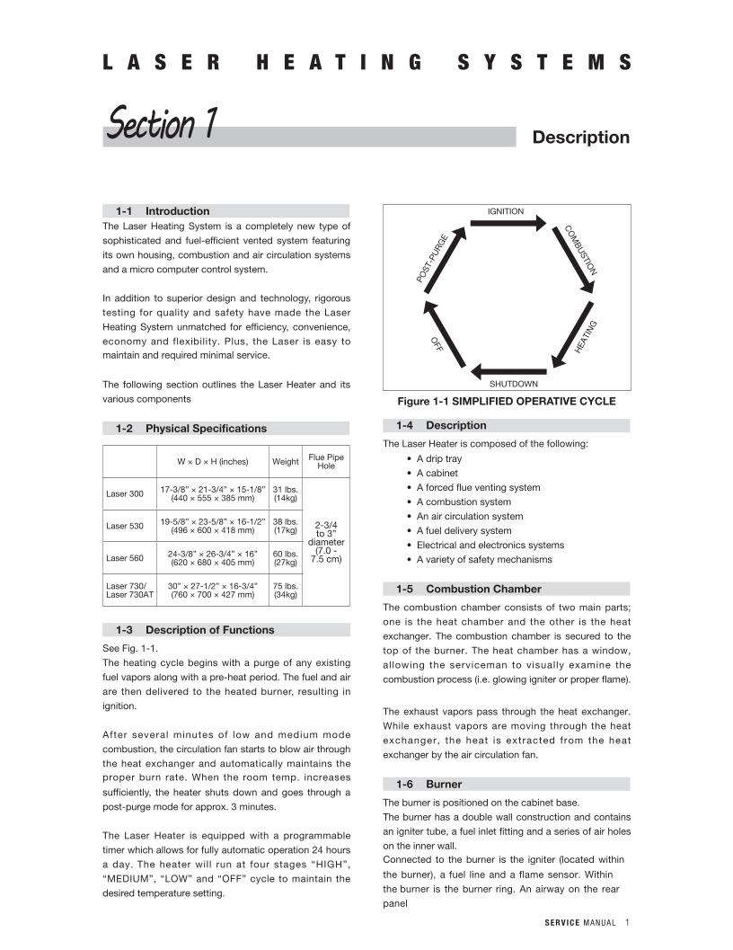
1-3 Description of Functions
See Fig. 1-1.
The heating cycle begins with a purge of any existing
fuel vapors along with a pre-heat period. The fuel and air
are then delivered to the heated burner, resulting in
ignition.
After several minutes of low and medium mode
combustion, the circulation fan starts to blow air through
the heat exchanger and automatically maintains the proper burn rate. When the room temp. increases
sufficiently, the heater shuts down and goes through a
post-purge mode for approx. 3 minutes.
The Laser Heater is equipped with a programmable
timer which allows for fully automatic operation 24 hours
a day. The heater will run at four stages “HIGH”,
“MEDIUM”, “LOW” and “OFF” cycle to maintain the
desired temperature setting.
1-4 Description
The Laser Heater is composed of the following:
• Adriptray
• Acabinet
• Aforcedflueventingsystem
• Acombustionsystem
• Anaircirculationsystem
• Afueldeliverysystem
• Electricalandelectronicssystems
• Avarietyofsafetymechanisms
1-5 Combustion Chamber
The combustion chamber consists of two main parts;
one is the heat chamber and the other is the heat
exchanger. The combustion chamber is secured to the
top of the burner. The heat chamber has a window,
al lowing the serviceman to visually examine the
combustion process (i.e. glowing igniter or proper flame).
The exhaust vapors pass through the heat exchanger.
While exhaust vapors are moving through the heat
exchanger, the heat is extracted from the heat
exchanger by the air circulation fan.
1-6 Burner
The burner is positioned on the cabinet base.
The burner has a double wall construction and contains
an igniter tube, a fuel inlet fitting and a series of air holes
on the inner wall.Connected to the burner is the igniter (located within
the burner), a fuel line and a flame sensor. Within
the burner is the burner ring. An airway on the rear
panel
DescriptionSection 1
SHUTDOWN
OFF
HEA
TIN
G
POST
-PU
RG
E
CO
MB
USTIO
N
IGNITION
Figure 1-1 SIMPLIFIED OPERATIVE CYCLE
2 S E R V I C E M A N U A L
L A S E R H E A T I N G S Y S T E M S
DescriptionSection 1
channels air from the intake fan of the combustion
blower to the burner. The flame rod sensor is mounted
through the wall of the burner.
Laser 300: 20470242 Laser 530: 20479842
Laser 560: 20470442 Laser 730: 20470642
1-7 Burner Ring Assembly
This assembly is designed to promote efficient burning.
The burner ring assembly is held by spring clips to
mounting posts within the burner.
Laser 300: 20479543 Laser 530: 20478343
Laser 560: 20478343 Laser 730: 20478643
1-8 Burner Mat / Coating
The textured burner mat (coating) insures the even
vaporization of fuel for proper combustion.
Burner mat — Laser 300/laser 730
Burner Coating — Laser 530/Laser560
Laser 300: 20479513 Laser 730: 20478613
1-9 Flame Rod Sensor
The flame rod sensor checks the condition of the flame
for proper burning.
The flame rod sensor is mounted through the wall of the
burner.
Laser 300: 20470211 Laser 530: 20479811
Laser 560: 20470411 Laser 730: 20470611
1-10 Igniter
The ceramic-type igniter is designed to pre-heat the
burner pot, to vaporize, and ignite the air/fuel mixture to
start the combustion process.
Laser 300/Laser 530/Laser 560/Laser 730: 20470218
1-11 Flue Pipe
The wall thickness which the flue pipe can be installed is from
4 in. (100 mm) to 9 in. (230 mm) The extension flue pipe
(option) is available for installation in wall thickness from 9 in.
(230 mm) to 13 in. (330 mm) This provides the flexibility to
meet the installation requirements of dwellings of various wall
thicknesses up to 13 inches (330 mm).
The flue pipe assembly is a “pipe-within-a-pipe” design which
consists of two concentric tubes. Outside air is drawn
through the cylindrical space between the tubes. Combustion
by-products are vented through the inner tube.
As cool air enters the flue pipe, it is heated by the hot air
that is exiting the system.
1-12 Blower Motor Assembly
The turbo fan is used for the combustion blower on the
intake air side only. The exhaust gas is expelled through
the flue pipe.
The blower motor assembly on Laser 560/730 is a dual
function fan with the intake air and exhaust air fans
mounted on a common shaft. Inside of the blower case
are separated into two compartments by a sealed plate.
One side is the intake air and the other is the exhaust air.
The intake fan draws in outside air through the flue pipe
for internal combustion. The exhaust fan, runs on a
common shaft with the intake fan, expels all combustion
by-products through the flue pipe.
The Laser Heater blower motor has 3-speeds. A
magnetic sensor insures proper fan speeds for each
burning mode.
The blower motor will keep running for 180 seconds
after the heater is turned off to exhaust vapor in the
system and cool off the unit.
Laser 300: 20470237 Laser 530: 20470337
Laser 560: 20470438 Laser 730: 20470638
1-13 Air Circulation Fan
The air circulation fan forces room air through the heat
exchanger, then out of the louvered front panel to be distributed throughout the room. The Laser
Heater circulation fan motor has three speeds. The
circulation fan will keep running for 180 seconds after
the heater shuts down. This cools the heater.
Laser 300: 20479671 Laser 530: 20474171
Laser 560: 20475071 Laser 730: 20475171
1-14 External Fuel Tank
The external tank (which generally is dealer installed)
should contain at least one shutoff valve, a fuel filter and
a vent. Installation of the tank should conform to local
regulations.
Only the Laser 560 gives the user the option of using either the removable fuel tank (part #20475922) or
external fuel tank.
S E R V I C E M A N U A L 3
L A S E R H E A T I N G S Y S T E M S
DescriptionSection 1
1-15 Fuel Pump
The fuel pump is mounted on top of the fuel sump. The
pump assembly consists of the pump solenoid and the
control circuit.
Laser 300: 20470219 Laser 530: 20470319
Laser 560: 20470419 Laser 730: 20470619
1-16 Control Circuit Board
The control circuit board provides safety timings,
controls relays and provides clock and thermostat
functions for the Laser Heater
Laser 300/Laser 530: 20470212
Laser 560: 20470412 Laser 730: 20470612
1-17 Room Temperature Sensor
The room temperature sensor, which is capable of sensing room temperatures within a range of 50°F
(10°C) to 90°F (32°C), can be wall mounted.
Approx. 8 feet (2.5 m) of wire is supplied with the sensor to facilitate wall mounting to a favorable
location. You can also use speaker wire to extend
the mounting location up to 20 feet (6m).
Laser 300/Laser 530/Laser 560/Laser 730: 20478373
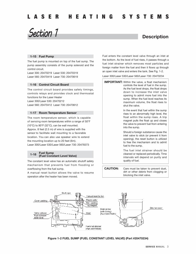
1-18 Fuel Sump(Fuel Constant Level Valve)
The constant level valve has an automatic shutoff safety
mechanism that prevents fuel f rom f looding or
overflowing from the fuel sump.
A manual reset button allows the valve to resume
operation after the heater has been moved.
Fuel enters the constant level valve through an inlet at
the bottom. As the level of fuel rises, it passes through a
fuel inlet strainer which removes most particles and
foreign matter from the fuel and then it flows up through
an open inlet valve and enters the tank. See Fig. 1-2.
Laser 300/Laser 530/Laser 560/Laser 730: 20470234
IMPORTANT: Within the valve, a float mechanism controls the level of fuel in the sump. As the fuel level drops, the float drops down to increase the inlet valve opening to admit more fuel into the sump. When the fuel level reaches its maximum volume, the float rises to shut the valve.
In the event that fuel within the sump rises to an abnormally high level, the float within the sump rises. A trip magnet pulls the float up and closes the valve to prevent fuel from entering into the sump.
Should a foreign substance cause the inlet valve to stick (or prevent it from opening), the reset button is utilized to free the mechanism and to admit fuel to the sump.
The fuel inlet strainer should be cleaned or replaced periodically. Time intervals will depend on purity and quality of fuel.
CAUTION: Care must be taken to prevent dust, dirt or other debris from clogging or blocking the inlet valve.
Figure 1-2 FUEL SUMP (FUEL CONSTANT LEVEL VALVE) (Part #20470234)
4 S E R V I C E M A N U A L
L A S E R H E A T I N G S Y S T E M S
DescriptionSection 1
1-19 Cloth Covered Exhaust PipeInsulating cloth covers are to be placed over all metal
surfaces of the exhaust line during installation. Since
combustion by-products are vented at elevated
temperatures, the exhaust pipe will become hot during operation. The insulating cloth cover protects
the user from accidental contact burn with these hot
metal surfaces.
Laser 300/Laser 530/Laser 560/Laser 730: 20474955
IMPORTANT: Do not operate the heater without the insulat ing covers. Dur ing instal lat ion make sure that al l exhaust lines are tightly connected.
1-20 Air Circulation Fan Filter (Cover)
The fan filter (cover) is an integral part of the fan
assembly and protects the user against physical injury
which could occur from accidental contact with the
revolving metal fan blade.
Laser 300: 20479540 Laser 530: 20479840
1-21 Fuse
In the event of a power surge or an internal wiring
hazard, the fuses will open and power to the heater will
be cut off. The fuses are rated at 250 V AC, 10-amps
and 250 V AC, 5-amps.
The electrical outlet into which the heater is
connected should be protected by at least a 15-amp.
fuse or circuit breaker.
Laser 300/Laser 530/Laser 560/Laser 730:
20470678 / 20470679
1-22 Overheat Protector Switch
Overheat Protector Switch is rated at 194°F (90°C).
Should a heater overheat (internal temperature rises
beyond 194°F (90°C)), the overheat protector switch
(also called a high limit switch) will open to shut off the
heater. Error code “E-12” will be displayed on the digital
indicator at this time. The overheat protector switch will
automatically reset after the heater has cooled down.
Once the heater has cooled to 158°F (70°C), the system
can be restarted manually as follows:
1. Press ON/OFF switch to “OFF”.
2. Allow heater to cool down.
3. Resolve the cause of the overheat.
4. Press ON/OFF switch to “ON” to start.
The heater will start with normal operation.
Laser 300/Laser 530/Laser 560/Laser 730: 20470206
1-23 Pressure Relief Plate
The pressure relief plate is located at the top part of
the heat exchanger, which effectively prevents
damage caused by misfire.
(Laser 300/530 only)
Laser 300 Laser 530: 20479530
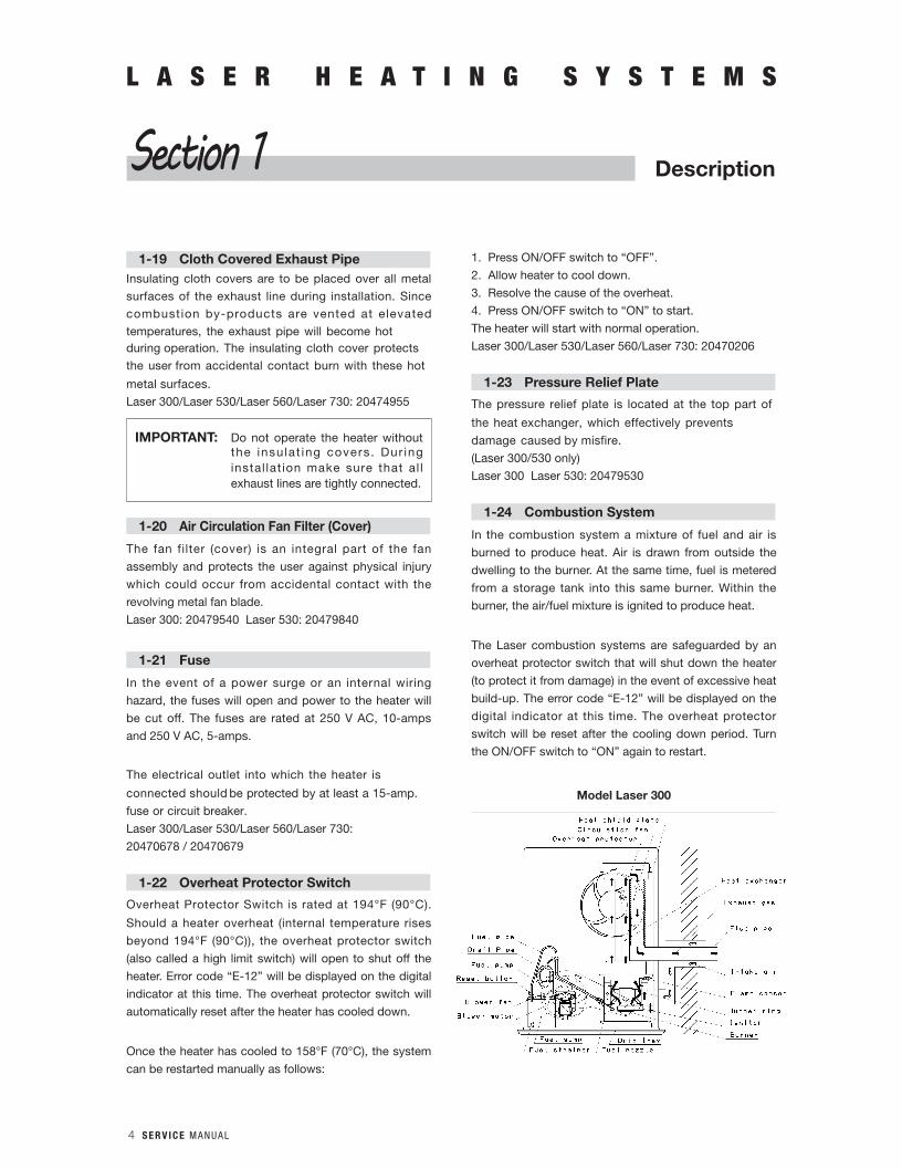
1-24 Combustion System
In the combustion system a mixture of fuel and air is
burned to produce heat. Air is drawn from outside the
dwelling to the burner. At the same time, fuel is metered
from a storage tank into this same burner. Within the
burner, the air/fuel mixture is ignited to produce heat.
The Laser combustion systems are safeguarded by an
overheat protector switch that will shut down the heater
(to protect it from damage) in the event of excessive heat
build-up. The error code “E-12” will be displayed on the
digital indicator at this time. The overheat protector
switch will be reset after the cooling down period. Turn
the ON/OFF switch to “ON” again to restart.
Model Laser 300
S E R V I C E M A N U A L 5
L A S E R H E A T I N G S Y S T E M S
DescriptionSection 1
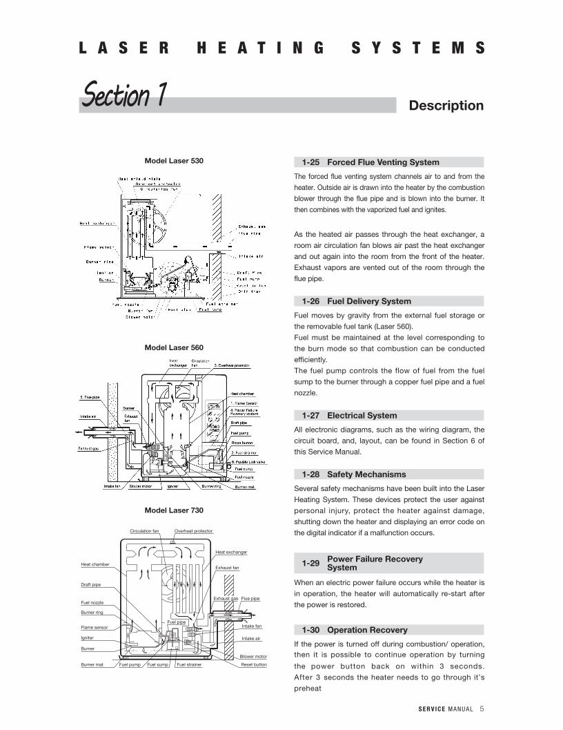
Model Laser 530
Model Laser 560
Model Laser 730
Fuel pipe
Heat chamber
Draft pipe
Fuel nozzle
Burner ring
Flame sensor
Igniter
Burner
Burner mat Fuel pump Fuel sump Fuel strainer
Blower motor
Intake air
Intake fan
Flue pipe
Exhaust fan
Heat exchanger
Overheat protectorCirculation fan
Exhaust gas
Reset button
1-25 Forced Flue Venting System
The forced flue venting system channels air to and from the
heater. Outside air is drawn into the heater by the combustion
blower through the flue pipe and is blown into the burner. It
then combines with the vaporized fuel and ignites.
As the heated air passes through the heat exchanger, a
room air circulation fan blows air past the heat exchanger
and out again into the room from the front of the heater.
Exhaust vapors are vented out of the room through the
flue pipe.
1-26 Fuel Delivery System
Fuel moves by gravity from the external fuel storage or
the removable fuel tank (Laser 560).
Fuel must be maintained at the level corresponding to
the burn mode so that combustion can be conducted
efficiently.
The fuel pump controls the flow of fuel from the fuel
sump to the burner through a copper fuel pipe and a fuel
nozzle.
1-27 Electrical System
All electronic diagrams, such as the wiring diagram, the
circuit board, and, layout, can be found in Section 6 of
this Service Manual.
1-28 Safety Mechanisms
Several safety mechanisms have been built into the Laser
Heating System. These devices protect the user against
personal injury, protect the heater against damage,
shutting down the heater and displaying an error code on
the digital indicator if a malfunction occurs.
1-29 Power Failure RecoverySystem
When an electric power failure occurs while the heater is
in operation, the heater will automatically re-start after
the power is restored.
1-30 Operation Recovery
If the power is turned off during combustion/ operation, then it is possible to continue operation by turning
the power button back on within 3 seconds.
After 3 seconds the heater needs to go through it’s
preheat

6 S E R V I C E M A N U A L
L A S E R H E A T I N G S Y S T E M S
DescriptionSection 1
cycle, before turning back on. The circulation fan motor
will remain on during this time.
1-31 Reigniting OperationStart to reignite (T1) by turning the operation switch ON
if the reigniting time becomes over 3 seconds after
turning the operation switch OFF during combustion.
(Include the unit OFF from the Save Mode and Timer Operation Mode.) Also, the fan motor keeps operating in
this condition.
1-32 Error Codes History
To show the error codes history, first turn the unit off (if
not already in off), then push the “DOWN” and “UP”
button at the same time for 3 seconds, and a buzzer will
sound. To get out of the error codes history, press the
“DOWN” and “UP” button again at the same time for 3
seconds. This will indicate the past 9 error codes. The
error codes are indicated as “XE YY”. (X stands for 1~9
with 1 being the most recent. Error codes more then 9
codes ago will be deleted. YY stands for the error code
or Altitude Setting – see High Altitude Setting Mode.)
If you press the “DOWN” button, the display shows
“AL YY””9E YY”····”1E YY””AL YY”····
If you press the “UP” button, the display shows
“AL YY””1E YY” · · · ·”9E YY””AL YY””1E
YY”····
When the unit is turned ON during Error Codes History,
the unit exits the Error Code History and starts normal
operation.
1-33 Igniting Failure Error Lock
If the igniting fault error “E-2” occurrs 3 times in a row,
then the display will show “E-22”, and it is not able to
reset by the power button but it can be reset by
unpluging the power cord for at least 30 minutes.
1-34 Burner Thermistor Normal DetectingTemperatures
L300 / L530 : above 120°C or 248 F normal
L560 / L730 : above 100°C or 212 F normal
1-35 Power Failure Recovery System
The error codes, weekly timer setting, ˚C/˚F setting,
Power Saver operation, and fuel pump flow setting are
stored in the involatile memory, and will not be erased
due to power failure. The time, however, is stored by the
capacitor, and will only last for so long. This could be 30
minutes or longer.
1-36 Backup Life
Back up time is more than 30 minutes(reference value)
The life guarantee is more than 10 years.
1-37 Deleting The Error Code History
To clear the error code history press the “AUTO” switch
for 3 seconds while in the Error Codes History. The
display will show “Er CL”, which will flash 3 times, and
then switch to time display.
1-38 Detection of Abnormal ElectricalFrequency Condition
When the electrical frequency of the power supplied to
the unit is abnormal and the power button is ON the unit
will display an error code of “E-0” and the unit will not start. To reset, turn the power button OFF and then
back ON.The judging range for the frequency is 55Hz<= or
<65Hz. Normal frequency is 60Hz.
1-39 Power Button Malfunction
If there is a problem with the power button the unit will
make a long buzzer beep sound (by 100msec. interval.),
which will indicate that a short circuit has occurred.
If the power button short circuit condition occurs for
more than 30 seconds, then the following happens:
• Flashallondisplay
• FlashthepowerLED
• Makeabeepsound
• All buttonsare invalid.Nobeep sound by pressing
buttons.To cance l beeping no ise turn the power button
OFF.
1-40 Low Voltage Detection
The unit will turn OFF with “E-0” when the low voltage
condition keeps for more than 10 seconds +/- 2
seconds.
1-41 Forced Flame Detection
If the flame is detected when the power button is turned
S E R V I C E M A N U A L 7
L A S E R H E A T I N G S Y S T E M S
DescriptionSection 1
ON or the unit comes back on from a power failure, the operation lamp will flash (0.5 Hz) and both the blower
motor and circulation fan motor will turn to high
revolution. The heater will turn ON if the flame goes out
within 30 seconds from turning ON or returning back
from power failure. The heater will be turned OFF for
safety with the error code of “E-23” if the flame is
detected for more than 30 seconds. However, both the
blower motor and circulation fan will continue to run on
high, until the flame is no longer detected.
1-42 Manual Ignitor Cleaning System
When the power button is OFF, press the “SET” and
“CLEAR” buttons at the same time for 3 seconds, the
unit will make a beep sound, indicating it is in Cleaning
Mode. LCD display will show “CL: 10” ~ ”CL: 01” (colon flashing) and make a countdown at every minute.
The countdown is shown on the right side of the
indicator in double figures as “10, 09 ... 02, 01”. The
blower motor turns at Low revolution while the igniter
is on for ten minutes. When the “SET and CLEAR”
buttons are pressed at the same time for 3
seconds during the Manual Igniting Cleaning modes,
the unit will make a beep sound and cancel Cleaning
Mode. When the heater is in operation and the “SET and
CLEAR” switches are pressed at the same time for 3
seconds, the heater will make a beep sound, but the
Manual Ignitor Cleaning mode will not accepted. If
the unit is in the Manual Ignitor Cleaning mode and
the power button is turned ON then the cleaning mode
will be cancelled and the heater will turn on.
1-43 Automatic Ignitor Cleaning System
The heater will turn OFF automatically when the time
becomes 2 AM during operation. After the post purge
finishes, the ignitor will be turned on and the blower
motor turns at Low revolution for cleaning operation
mode. LCD display will change to show “CL:10” ~
“CL:01” (colon flashing) and make a countdown at every
minute. The countdown is shown on the right side of the
display as “10, 09 ... 02, 01”. After the countdown
finishes the unit will shift back to normal operation.
1-44 Manual Combustion Operation Mode
To put the unit in Manual Fuel Pump Operation Mode,
first have the power button “ON”, and then push and
hold the “DOWN” and “UP” button at the same time for 3 seconds. A buzzer sound will occur. To return to
normal operation push these buttons again at the same
time for 3 seconds, the unit will then shift back to the
Normal Operation Mode and will make a buzzer sound. Manual Fuel Pump Operation Mode cannot be cancelled
by turning off the power button. The unit will turn off, however, when unit is turned back on, it will be in
Manual Fuel Pump Operation Mode again.
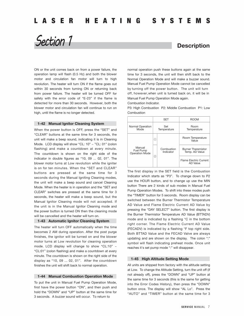
Combustion Indicator.
P3: High Combustion P2: Middle Combustion P1: Low
Combustion
SET ROOM
Normal Operation Mode
SetTemperature
RoomTemperature
ManualFuel Pump
Operation Mode
1
Combustion Indicator
Room Temperature Value
2
Burner Theremistor Temp. AD Value
Flame Electric Current AD Value
The first display in the SET field is the Combustion
Indicator which starts as “P3”. To change down to P2
use the HOUR button, and to change up use the MIN
button There are 2 kinds of sub modes in Manual Fuel
Pump Operation Modes. To shift into these modes push
the “TIMER” button for 5 seconds. Room display can be
switched between the Burner Thermistor Temperature
AD Value and Flame Electric Current AD Value by
pressing the “DAY SELECT” button. The first display is
the Burner Thermistor Temperature AD Value (BTTADV)
mode and is indicated by a flashing °C in the bottom
right corner. The Flame Electric Current AD Value
(FECADV) is indicated by a flashing °F top right side.
Both BTTAD Value and the FECAD Valve are always
updating and are shown on the display. The colon “:”
symbol will flash indicating preheat mode. Once unit reaches it's set pump mode “:” will disappear.
1-45 High Altitude Setting Mode
All units are shipped from factory with the altitude setting
at Low. To change the Altitude Setting, turn the unit off (if
not already off), press the “DOWN” and “UP” button at
the same time for 3 seconds (this is the same for getting
into the Error Codes History), then press the “DOWN”
button once. The display will show “AL Lo”. Press the
“AUTO” and “TIMER” button at the same time for 3
8 S E R V I C E M A N U A L
seconds. The display will show “AL Hi”, flash for 3 times,
and then shift to off mode. If the power button is turned
on when flashing “AL Hi” the display will switch from “AL
Hi” flashing to temperature and start normal operation. To
switch back to Lo altitude setting repeat the steps above.
When switching to Hi altitude setting mode, the fuel
pump flow rates levels will all be switched to Level 1 (see
Flow Volume Setting Mode for the Fuel Pump below),
which is a 10% decrease in fuel flow. In the high altitude
setting mode “AL Hi” the fuel flow rate is L1=1, L2=1,
L3=1. The Lo altitude setting mode is 5 (meaning fuel
flow rates are L1= 5, L2= 5, L3= 5).
If the fuel pump flow rate setting mode is changed to
L1=1, L2=1, L3=1, it is shifted to “Hi” altitude setting
mode automatically.
1-46 Combustion Cleaning ModeWhen the unit is in the high combustion mode for more
than 2 hours continuously, it will automatically shift
to low combustion for 5 minutes. During Combustion
Cleaning mode the unit will change to medium
combustion for 30 seconds, then to low combustion
for 4 minutes, and back to medium combustion for 30
seconds, and then to high combustion. The display will
show “CL:05” (colon flashes at 1.0Hz, and counts
down every minute. The countdown is shown on the
right side of the display in double figures as “04, 03,
02, 01”.
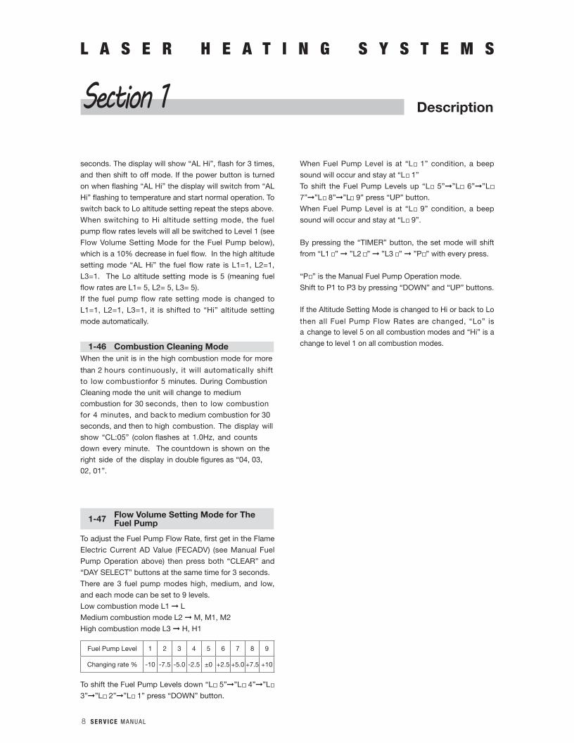
1-47 Flow Volume Setting Mode for TheFuel Pump
To adjust the Fuel Pump Flow Rate, first get in the Flame
Electric Current AD Value (FECADV) (see Manual Fuel
Pump Operation above) then press both “CLEAR” and
“DAY SELECT” buttons at the same time for 3 seconds.
There are 3 fuel pump modes high, medium, and low,
and each mode can be set to 9 levels.
Low combustion mode L1 L
Medium combustion mode L2 M, M1, M2
High combustion mode L3 H, H1
Fuel Pump Level 1 2 3 4 5 6 7 8 9
Changing rate % -10 -7.5 -5.0 -2.5 ±0 +2.5 +5.0 +7.5 +10
To shift the Fuel Pump Levels down “L 5””L 4””L
3””L 2””L 1” press “DOWN” button.
When Fuel Pump Level is at “L 1” condition, a beep
sound will occur and stay at “L 1”
To shift the Fuel Pump Levels up “L 5””L 6””L
7””L 8””L 9” press “UP” button.
When Fuel Pump Level is at “L 9” condition, a beep
sound will occur and stay at “L 9”.
By pressing the “TIMER” button, the set mode will shift
from “L1 ” ”L2 ” ”L3 ” ”P ” with every press.
“P ” is the Manual Fuel Pump Operation mode.
Shift to P1 to P3 by pressing “DOWN” and “UP” buttons.
If the Altitude Setting Mode is changed to Hi or back to Lo
then all Fuel Pump Flow Rates are changed, “Lo” is a change to level 5 on all combustion modes and “Hi” is a
change to level 1 on all combustion modes.
L A S E R H E A T I N G S Y S T E M S
DescriptionSection 1
S E R V I C E M A N U A L 9
L A S E R H E A T I N G S Y S T E M S
2-1 Introductlon
Heater maintenance is divided into two classifications; routine maintenance, which is required to keep the heater in good operating condition; and corrective maintenance, which is necessary in repairing any malfunctions.
2-2 Routine Maintenance
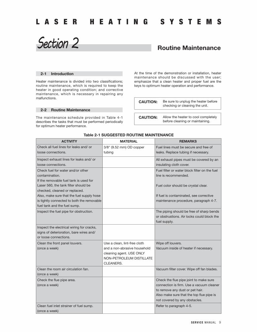
The maintenance schedule provided in Table 4-1 describes the tasks that must be performed periodically for optimum heater performance.
At the time of the demonstration or installation, heater maintenance should be discussed with the user; emphasize that a clean heater and proper fuel are the keys to optimum heater operation and performance.
CAUTION: Be sure to unplug the heater before checking or cleaning the unit.
CAUTION: Allow the heater to cool completely before cleaning or maintaining.
Routine MaintenanceSection 2
Table 2-1 SUGGESTED ROUTINE MAINTENANCE
ACTIVITY MATERIAL REMARKS
Check all fuel lines for leaks and/ or
loose connections.
3/8" (9.52 mm) OD copper
tubing
Fuel lines must be secure and free of
leaks. Replace tubing if necessary.
Inspect exhaust lines for leaks and/ or
loose connections.
All exhaust pipes must be covered by an
insulating cloth cover.
Check fuel for water and/or other
contamination.
If the removable fuel tank is used for Laser 560, the tank filter should be
checked, cleaned or replaced.
Also, make sure that the fuel supply hose
is tightly connected to both the removable
fuel tank and the fuel sump.
Fuel filter or water block filter on the fuel
line is recommended.
Fuel color should be crystal clear.
If fuel is contaminated, see corrective
maintenance procedure, paragraph 4-7.
Inspect the fuel pipe for obstruction. The piping should be free of sharp bends
or obstrustions. Air locks could block the
fuel supply.
Inspect the electrical wiring for cracks,
signs of deterioration, bare wires and/or loose connections.
Clean the front panel louvers.
(once a week)
Use a clean, Iint-free cloth
and a non-abrasive household
cleaning agent. USE ONLY
NON-PETROLEUM DISTILLATE
CLEANERS.
Wipe off louvers.
Vacuum inside of heater if necessary.
Clean the room air circulation fan.
(once a week)
Vacuum filter cover. Wipe off fan blades.
Check the flue pipe area.
(once a week)
Check the flue pipe joint to make sure
connection is firm. Use a vacuum cleaner
to remove any dust or pet hair. Also make sure that the top flue pipe is
not covered by any obstacles.
Clean fuel inlet strainer of fuel sump.
(once a week)
Refer to paragraph 4-5.

10 S E R V I C E M A N U A L
L A S E R H E A T I N G S Y S T E M S
Routine MaintenanceSection 2
ACTIVITY MATERIAL REMARKS
Inspect the burner ring, and the flame
sensor.
(at least every year)
Clean all carbon deposits. Replace if
excessively warped or cracked.
NOTE: If the gasket is torn when
components are removed, the
gasket must be replaced.
Clean the heat chamber and the burner
assembly.
(at least every year)
Brush, scrape and vacuum all
carbon deposits from the interior of
the heat chamber and burner air
holes. Clean all carbon on the burner
bottom. Use a small, stiff brush or a
short piece of soft copper wire to
clean any blocked air holes. Replace
the burner mat, if necessary.
Clean the igniter. Gently scrape any carbon deposits from
igniter.
WARNING: Be careful when you remove the igniter, it may
be difficult to loosen and
may crack.
Check air intake pipe, exhaust pipe, and
blower motor assembly.
(every year)
Replace the air line if it is worn or broken.
Also, clean the exhaust fan if necessary.
Check for carbon build-up on or inside
fuel nozzle.
(every year)
Disconnect the fuel pipe assembly from
the fuel nozzle. Clean inside the nozzle with the proper sized drill bit or piece
of straight wire.
CAUTION: If any obstruction is felt,
remove fuel nozzle before
proceeding.
S E R V I C E M A N U A L 11
L A S E R H E A T I N G S Y S T E M SL A S E R H E A T I N G S Y S T E M S
Servicing
3-1 Introduction
Servicing is required when the heater is running at
proper efficiency. This section covers the possible
causes and the corrective procedures for efficiency losses.
Signs of improper heater efficiency and performance
would be:
n A yellow, high flame.
n A whistling noise.
n Smoke from the flue pipe exhaust .
n Heavy soot and carbon build up in burner, heat chamber and/ or heat exchanger.
n Lowered heat output.
n Failed ignition.n Failure to maintain combustion. n
Noise from the blower motor.
3-2 Cleaning The HeatExchanger and Burner
Under normal running conditions, very little soot will be
formed inside the burner. A light covering of soot will not
affect the performance of the heater. Thus the heater
should not need cleaning. If a heavy soot build up
occurs, follow the outlined steps for opening and
cleaning the heater.
The burner is assembled using gaskets to maintain its
air-tightness. If these gaskets are damaged, the air may
cause soot and/or cause noise.
NOTE: When cleaning the burner, it is recommended
to slide the heat exchanger gasket onto a
piece of cardboard. Or replace the gaskets, if
necessary, carefully remove the gaskets because they are easily damaged.
1. Remove front panel assembly.
2. Remove top plate.
3. Remove top heat shield.
4. Remove heat exchanger.
5. Remove heat shield.
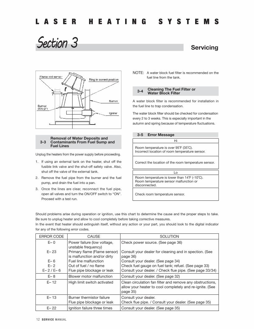
6. Remove flame rod sensor.
7. Turn burner ring counter-clockwise to remove. Burner ring is secured by three side pins in the burner pot.
If burner ring does not turn, pull it up slightly to loosen
the spring clips.
8. Use a wire brush to clean inside the heat exchanger and burner air holes. Clean all carbon on the burner bottom by using a flat-bladed screw driver or wire brush. Vacuum all burner deposits and wipe clean.
NOTE: Make sure that all air inlet openings are clear.
9. Remove the igniter and the fuel nozzle from the
burner.
10. The burner ring may deform and deteriorate after
several years of use and should be cleaned and
inspected before reinstallation. If the burner ring is
badly warped, cracked or deteriorated, it
should be replaced.
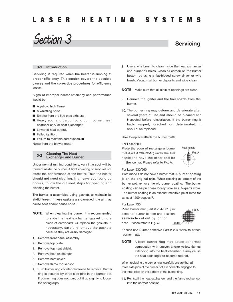
How to replace/attach the burner matts;
For Laser 300Place the edge of rectangular burner
mat (Part # 20479513) under the fuel
nozzle and have the other end be
in the center. Please refer to Fig. A.
For Laser 530/560Both models do not have a burner mat. A burner coating
is on the original units. When cleaning up bottom of the
burner pot, remove the old burner coating. The burner
coating can be purchase locally from an auto-parts store.
The burner coating is an exhaust manifold paint rated for
at least 1200 degees F.
For Laser 730
Place burner mat (Part # 20478613) in
center of burner bottom and position semicircle cut out by ignitor
area. Please refer to Fig. C
* Please use Burner adhesive Part # 20478526 to attach
burner matts
NOTE: A bent burner r ing may cause abnormal
combustion with uneven and/or yellow flames extending into the heat chamber. It may cause
the heat exchanger to become red hot.
When replacing the burner ring, carefully ensure that all three side pins of the burner pot are correctly engaged to
the three clips on the bottom of the burner ring.
11. Reinstall the heat exchanger and the flame rod sensor into the correct position.
Section 3
Fig. A
Fuel nozzle
Fig. C
Igniter
12 S E R V I C E M A N U A L
L A S E R H E A T I N G S Y S T E M SL A S E R H E A T I N G S Y S T E M S
ServicingSection 3
3-3Removal of Water Deposits and Contaminants From Fuel Sump and Fuel Lines
Unplug the heaters from the power supply before proceeding.
1. If using an external tank on the heater, shut off the
fusible link valve and the shut-off safety valve. Also,
shut off the valve of the external tank.
2. Remove the fuel pipe from the burner and the fuel
pump, and drain the fuel into a pan.
3. Once the lines are clear, reconnect the fuel pipe,
open all valves and turn the ON/OFF switch to “ON”.
Proceed with a test run.
NOTE: A water block fuel filter is recommended on the fuel line from the tank.
3-4 Cleaning The Fuel Filter orWater Block Filter
A water block filter is recommended for installation in
the fuel line to trap condensation.
The water block filter should be checked for condensation
every 2 to 3 weeks. This is especially important in the
autumn and spring because of temperature fluctuations.
3-5 Error Message
Hi
Room temperature is over 95˚F (35˚C).Incorrect location of room temperature sensor.
Correct the location of the room temperature sensor.
Lo
Room temperature is lower than 14˚F (-10˚C).Room temperature sensor malfunction or disconnected.
Check room temperature sensor.
Should problems arise during operation or ignition, use this chart to determine the cause and the proper steps to take.
Be sure to unplug heater and allow to cool completely before taking corrective measures.
In the event that heater should extinguish itself, without any action or your part, you should look to the digital indicator
for any of the following error codes.
ERROR CODE CAUSE SOLUTION
E– 0
E– 23
E– 6E– 2
E– 2 / E– 6
Power failure (low voltage, unstable frequency)Primary flame (Flame sensor) is malfunction and/or dirtyFuel line malfunction Out of fuel / no flameFlue pipe blockage or leak
Check power source. (See page 36)
Consult your dealer for cleaning and in spection. (See page 36)Consult your dealer. (See page 34)Check fuel gauge on fuel tank; refuel. (See page 33)Consult your dealer. / Check flue pipe. (See page 33/34)
E– 8 Blower motor malfunction Consult your dealer. (See page 32)
E– 12 High limit switch activated Clean circulation fan filter and remove any obstructions, allow your heater to cool completely and re-ignite. (See page 35)
E– 13 Burner thermistor failureFlue pipe blockage or leak
Consult your dealer.Check flue pipe. / Consult your dealer. (See page 35)
E– 22 Ignition failure three times Consult your dealer. (See page 35)
S E R V I C E M A N U A L 13
L A S E R H E A T I N G S Y S T E M SL A S E R H E A T I N G S Y S T E M S
ServicingSection 3
3-6 Inspect Intake/Exhaust Air Lines
Verify that all intake/exhaust air lines are free of leaks and that there are no loose connections, as specified below:
STEP 1: Remove Insulating Cloth Cover
Remove the insulating cloth covers from all exhaust lines.
STEP 2: Inspection of Intake/Exhaust Air Lines
A. Visually inspect both the intake air and exhaust lines for obvious cracks, leaks or loose connections. Black carbon deposits may be evidence of leakage.
B. Be sure that all lines are installed tightly and securely, especially at the joints.
C. Turn heater to “ON”.
D. Carefully apply a small amount of soapy water (with a paint brush) to the surface areas and joints of the intake/exhaust air lines.
Any leaks that may exist will be readily identified by the appearance of bubbles.
STEP 3: Return to Operating Condition
A. Turn heater to “OFF”.
B. Dry all lines with paper towels.
C. Repair any leaks that have been found (if necessary, replace the tubing or O-ring).
D. Replace insulating cloth covers.
3-7 Verify Igniter Operation
Visually inspect igniter operation.
WARNING: Heater is operational during this inspection, Avoid direct contact with any heated or electrical compoments.
STEP 1: Prepare for InspectionRemove grille and front panel assembly.
STEP 2: Visual InspectionA. Remove the igniter half way.
B. Turn heater to “ON”.
C. Igniter should start to glow red within 30-40 seconds.
If the igniter does not glow red, check for power at
120V AC (or 220V AC) and resistance 17 to 19Ω at
room temperature of 73˚F (23˚C).
CAUTION: If igniter malfunctions, do not turn the heater to “ON” repeatedly.Otherwise, excess fuel may drain in the burner pot.
STEP 3: Reassembly of HeaterTurn the heater to “OFF” and replace the front panel
assembly.
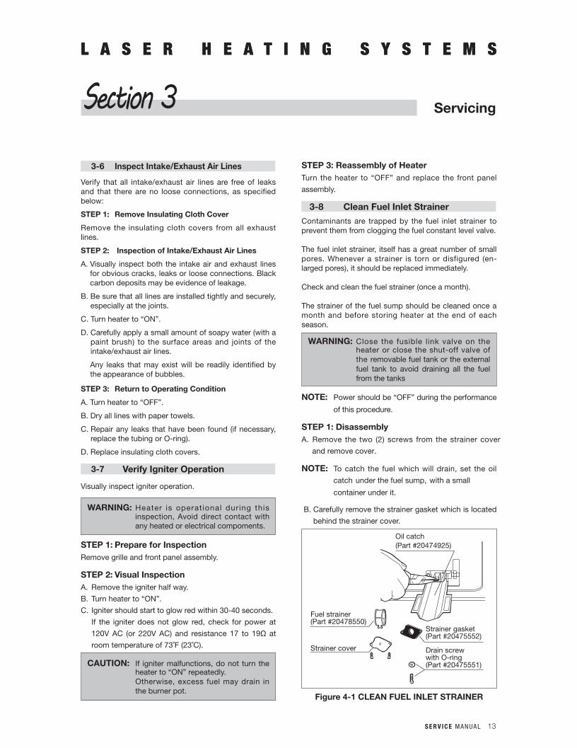
3-8 Clean Fuel Inlet Strainer
Contaminants are trapped by the fuel inlet strainer to prevent them from clogging the fuel constant level valve.
The fuel inlet strainer, itself has a great number of small pores. Whenever a strainer is torn or disfigured (en- larged pores), it should be replaced immediately.
Check and clean the fuel strainer (once a month).
The strainer of the fuel sump should be cleaned once a month and before storing heater at the end of each season.
WARNING: Close the fusible link valve on the heater or close the shut-off valve of the removable fuel tank or the external fuel tank to avoid draining all the fuel from the tanks
NOTE: Power should be “OFF” during the performance
of this procedure.
STEP 1: DisassemblyA. Remove the two (2) screws from the strainer cover
and remove cover.
NOTE: To catch the fuel which will drain, set the oil
catch under the fuel sump, with a small
container under it.
B. Carefully remove the strainer gasket which is located
behind the strainer cover.
Oil catch(Part #20474925)
Fuel strainer(Part #20478550)
Strainer gasket(Part #20475552)
Drain screwwith O-ring(Part #20475551)
Strainer cover
Figure 4-1 CLEAN FUEL INLET STRAINER
14 S E R V I C E M A N U A L
L A S E R H E A T I N G S Y S T E M SL A S E R H E A T I N G S Y S T E M S
ServicingSection 3
STEP 2: Inspection and CleaningA. Pull the fuel strainer out of the fuel sump.
B. If the strainer is dirty (but undamaged), rinse the fuel
strainer in fresh, clean kerosene to remove all
particles. Replace the fuel strainer if necessary.
C. To drain the upper portion of the fuel sump, carefully loosen the drain screw, there is no need to remove
(phillips head screw) which is located to the left of
strainer cover.
STEP 3: ReassemblyA. Push the new cleaned fuel strainer back into the
bottom of the fuel sump.
B. Replace both the strainer gasket and the strainer
cover if necessary.
NOTE: Carefully align the screw holes in the gasket
and strainer cover.
C. Wipe up any spilled fuel.
NOTE: Be sure to unscrew the drain screw to remove
all the remaining fuel from the fuel sump at the
end of each season.
3-9 Replacement of Fuses
A short circuit or similar electrical malfunction could
cause a fuse to blow. Troubleshoot the cause of the
blown fuse.
Replace the fuse as follows:
WARNING: Do not replace fuses while power is “ON”.
STEP 1: Removal of FuseA. Unplug the heater. Remove the front panel assembly.
B. Remove the fuse from fuse holder, located on the
main circuit board.
STEP 2: Installation of New FuseA. Install new fuses into the fuse holder. The fuses must
be a 125V, 10 amp type and a 125V, 3 amp type are
marked on the main circuit board. Do not use
oversized fuses.
B. Replace the front panel assembly and plug the heater
into the electrical outlet.
IMPORTANT: Whenever the heater is unplugged, t he se t -back t ime r mus t be reprogrammed after the power is restored.
3-10 Fuel Contamination
Fuel contamination is often difficult to diagnose, even
though it will adversely affect the heater operation and
performance. The best course of action to take when fuel contamination is suspected is to examine all of
the system’s fuel filters, beginning with the fuel storage
tank. If a Laser kerosene lifter is part of the fueling
system, examine and clean the unit’s filter, as well as
the strainer located in the fuel sump.
When it has been determined that water or some other
contaminant has infiltrated the fuel, the following
procedure should be used:
WARNING: Before proceeding further, unplug the heater.
STEP 1: Remove ContaminationA. Close the fuel valve of the tank and the fusible link
valve on the heater.
B. Drain the contaminants from the external tank, or
disconnect the fuel supply hose and clean the
contamination from the removable fuel tank (Laser
560). Refill with fresh, clean fuel.
STEP 2: Clean the HeaterA. Clean the fuel inlet strainer inside of the fuel sump.
B. Remove the front panel assembly and the fuel pump on
the fuel sump. Clean the fuel pump filter.
C. Using clean paper towels, thoroughly wipe the bottom
of the burner, the burner ring, the flame rod sensor,
and the heat chamber.
Replace the burner mat, if necessary.
STEP 3: Reinstall Cleaned ComponentsA. Replace the components correctly and install a new
gasket, if necessary.
B. Open the fuel valve on the external tank, the
removable fuel tank, and the fusible valve, replace all
covers and supply power to the heater.
If the problem still exists and contaminated fuel is
suspected, it can be checked.The fuel filter or the water
block filter in the fuel line is always required to minimize
any fuel contamination.
Test run the heater to see if the problem clears up, using
new clean fuel.
S E R V I C E M A N U A L 15
L A S E R H E A T I N G S Y S T E M SL A S E R H E A T I N G S Y S T E M S
ServicingSection 3
3-11 Cleaning Blower Motor (Only Laser 560/730)
Usage of poor-quality kerosene (High sulfer, high
viscosity, etc.) or fuel other than No. 1-K kerosene, will
cause heavy carbon to build up on the exhaust fan or
the blower motor assembly. This may cause the exhaust
fan to stick or the blower motor to malfunction.
These will result in noise in the blower motor assembly.
The blower motor assembly must be disassembled
according to the following procedure. Clean the fan or
replace the blower motor (and other parts), if necessary.
STEP 1: Cleaning the Exhaust FanA. Remove the blower motor case from the heater base.
Remove the top cover.
B. Loosen the set screw that secures the exhaust fan to
the motor shaft. Remove the retaining nut.
NOTE: 2.0 mm (5/64 in.) hex key and 7 mm (9/32 in.)
socket are required.
C. Remove the exhaust fan. Clean the fan and the
housing.
D. Re-assemble the exhaust fan and test for proper
operation before re-installation.
STEP 2: Replacing the Blower Motor or Intake FanA. Remove the spacer from the shaft.
B. Remove five (5) screws from the blower motor
bracket.
C. Remove the motor wire bushing and then the blower
motor from the housing.
D. Loosen the set screw and remove intake fan.
E. Remove the two (2) screws fixed on the blower motor
bracket of blower motor.
16 S E R V I C E M A N U A L
L A S E R H E A T I N G S Y S T E M S
ServicingSection 3
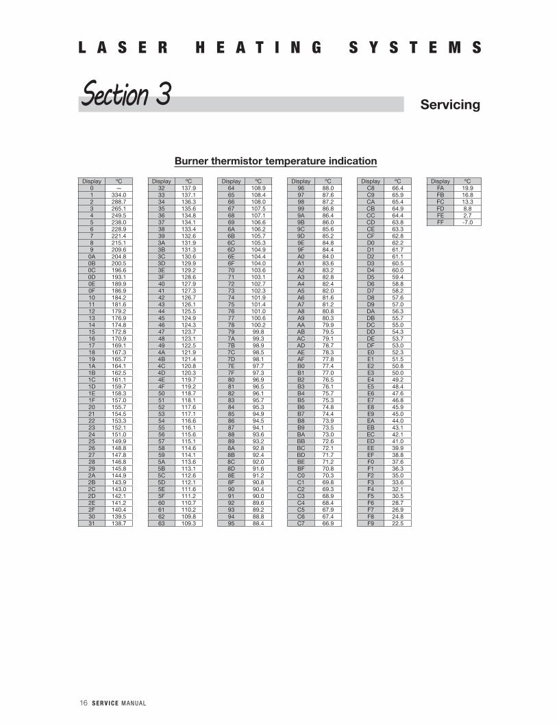
Burner thermistor temperature indication
Display ºC Display ºC Display ºC Display ºC Display ºC Display ºC0 — 32 137.9 64 108.9 96 88.0 C8 66.4 FA 19.91 334.0 33 137.1 65 108.4 97 87.6 C9 65.9 FB 16.82 288.7 34 136.3 66 108.0 98 87.2 CA 65.4 FC 13.33 265.1 35 135.6 67 107.5 99 86.8 CB 64.9 FD 8.84 249.5 36 134.8 68 107.1 9A 86.4 CC 64.4 FE 2.75 238.0 37 134.1 69 106.6 9B 86.0 CD 63.8 FF -7.06 228.9 38 133.4 6A 106.2 9C 85.6 CE 63.37 221.4 39 132.6 6B 105.7 9D 85.2 CF 62.88 215.1 3A 131.9 6C 105.3 9E 84.8 D0 62.29 209.6 3B 131.3 6D 104.9 9F 84.4 D1 61.7
0A 204.8 3C 130.6 6E 104.4 A0 84.0 D2 61.10B 200.5 3D 129.9 6F 104.0 A1 83.6 D3 60.50C 196.6 3E 129.2 70 103.6 A2 83.2 D4 60.00D 193.1 3F 128.6 71 103.1 A3 82.8 D5 59.40E 189.9 40 127.9 72 102.7 A4 82.4 D6 58.80F 186.9 41 127.3 73 102.3 A5 82.0 D7 58.210 184.2 42 126.7 74 101.9 A6 81.6 D8 57.611 181.6 43 126.1 75 101.4 A7 81.2 D9 57.012 179.2 44 125.5 76 101.0 A8 80.8 DA 56.313 176.9 45 124.9 77 100.6 A9 80.3 DB 55.714 174.8 46 124.3 78 100.2 AA 79.9 DC 55.015 172.8 47 123.7 79 99.8 AB 79.5 DD 54.316 170.9 48 123.1 7A 99.3 AC 79.1 DE 53.717 169.1 49 122.5 7B 98.9 AD 78.7 DF 53.018 167.3 4A 121.9 7C 98.5 AE 78.3 E0 52.319 165.7 4B 121.4 7D 98.1 AF 77.8 E1 51.51A 164.1 4C 120.8 7E 97.7 B0 77.4 E2 50.81B 162.5 4D 120.3 7F 97.3 B1 77.0 E3 50.01C 161.1 4E 119.7 80 96.9 B2 76.5 E4 49.21D 159.7 4F 119.2 81 96.5 B3 76.1 E5 48.41E 158.3 50 118.7 82 96.1 B4 75.7 E6 47.61F 157.0 51 118.1 83 95.7 B5 75.3 E7 46.820 155.7 52 117.6 84 95.3 B6 74.8 E8 45.921 154.5 53 117.1 85 94.9 B7 74.4 E9 45.022 153.3 54 116.6 86 94.5 B8 73.9 EA 44.023 152.1 55 116.1 87 94.1 B9 73.5 EB 43.124 151.0 56 115.6 88 93.6 BA 73.0 EC 42.125 149.9 57 115.1 89 93.2 BB 72.6 ED 41.026 148.8 58 114.6 8A 92.8 BC 72.1 EE 39.927 147.8 59 114.1 8B 92.4 BD 71.7 EF 38.828 146.8 5A 113.6 8C 92.0 BE 71.2 F0 37.629 145.8 5B 113.1 8D 91.6 BF 70.8 F1 36.32A 144.9 5C 112.6 8E 91.2 C0 70.3 F2 35.02B 143.9 5D 112.1 8F 90.8 C1 69.8 F3 33.62C 143.0 5E 111.6 90 90.4 C2 69.3 F4 32.12D 142.1 5F 111.2 91 90.0 C3 68.9 F5 30.52E 141.2 60 110.7 92 89.6 C4 68.4 F6 28.72F 140.4 61 110.2 93 89.2 C5 67.9 F7 26.930 139.5 62 109.8 94 88.8 C6 67.4 F8 24.831 138.7 63 109.3 95 88.4 C7 66.9 F9 22.5
S E R V I C E M A N U A L 17
L A S E R H E A T I N G S Y S T E M S
ServicingSection 3
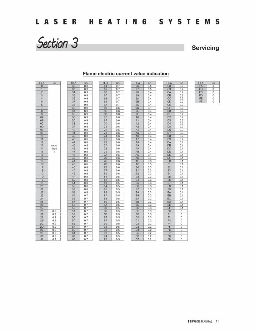
Flame electric current value indication
HEX μA HEX μA HEX μA HEX μA HEX μA HEX μA0 32 0.9 64 0.7 96 0.5 C8 0.2 FA 01 33 0.9 65 0.7 97 0.5 C9 0.2 FB 02 34 0.9 66 0.7 98 0.4 CA 0.2 FC 03 35 0.9 67 0.7 99 0.4 CB 0.2 FD 04 36 0.9 68 0.7 9A 0.4 CC 0.2 FE 05 37 0.9 69 0.7 9B 0.4 CD 0.2 FF 06 38 0.9 6A 0.7 9C 0.4 CE 0.27 39 0.9 6B 0.6 9D 0.4 CF 0.28 3A 0.9 6C 0.6 9E 0.4 D0 0.29 3B 0.9 6D 0.6 9F 0.4 D1 0.2
0A 3C 0.9 6E 0.6 A0 0.4 D2 0.20B 3D 0.9 6F 0.6 A1 0.4 D3 0.20C 3E 0.9 70 0.6 A2 0.4 D4 0.20D 3F 0.8 71 0.6 A3 0.4 D5 0.20E 40 0.8 72 0.6 A4 0.4 D6 0.20F 41 0.8 73 0.6 A5 0.4 D7 0.210 42 0.8 74 0.6 A6 0.4 D8 0.211 43 0.8 75 0.6 A7 0.4 D9 0.212 44 0.8 76 0.6 A8 0.4 DA 0.113 more 45 0.8 77 0.6 A9 0.4 DB 0.114 than 46 0.8 78 0.6 AA 0.4 DC 0.115 1 47 0.8 79 0.6 AB 0.4 DD 0.116 48 0.8 7A 0.6 AC 0.4 DE 0.117 49 0.8 7B 0.6 AD 0.4 DF 0.118 4A 0.8 7C 0.6 AE 0.3 E0 0.119 4B 0.8 7D 0.6 AF 0.3 E1 0.11A 4C 0.8 7E 0.6 B0 0.3 E2 0.11B 4D 0.8 7F 0.6 B1 0.3 E3 0.11C 4E 0.8 80 0.6 B2 0.3 E4 0.11D 4F 0.8 81 0.5 B3 0.3 E5 0.11E 50 0.8 82 0.5 B4 0.3 E6 0.11F 51 0.8 83 0.5 B5 0.3 E7 0.120 52 0.8 84 0.5 B6 0.3 E8 0.121 53 0.8 85 0.5 B7 0.3 E9 0.122 54 0.8 86 0.5 B8 0.3 EA 0.123 55 0.7 87 0.5 B9 0.3 EB 0.124 56 0.7 88 0.5 BA 0.3 EC 0.125 57 0.7 89 0.5 BB 0.3 ED 0.126 58 0.7 8A 0.5 BC 0.3 EE 0.127 59 0.7 8B 0.5 BD 0.3 EF 0.128 0.9 5A 0.7 8C 0.5 BE 0.3 F0 029 0.9 5B 0.7 8D 0.5 BF 0.3 F1 02A 0.9 5C 0.7 8E 0.5 C0 0.3 F2 02B 0.9 5D 0.7 8F 0.5 C1 0.3 F3 02C 0.9 5E 0.7 90 0.5 C2 0.3 F4 02D 0.9 5F 0.7 91 0.5 C3 0.3 F5 02E 0.9 60 0.7 92 0.5 C4 0.2 F6 02F 0.9 61 0.7 93 0.5 C5 0.2 F7 030 0.9 62 0.7 94 0.5 C6 0.2 F8 031 0.9 63 0.7 95 0.5 C7 0.2 F9 0

18 S E R V I C E M A N U A L

S E R V I C E M A N U A L 19
L A S E R H E A T I N G S Y S T E M S
Trouble ShootingSection 4
4-1 Electrical System
BL
GY
BK
RD
GN
BK
YL
WT
BL WT RD
RD
YL
OR
RD
BN
CL
20 S E R V I C E M A N U A L
L A S E R H E A T I N G S Y S T E M S
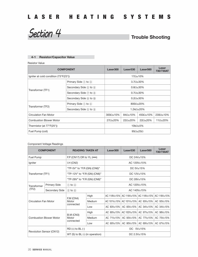
4-1 Resistor/Capacitor Value
Resistor Value
COMPONENT Laser300 Laser530 Laser560 Laser730/730AT
Igniter at cold condition (73°F(23°)) 17Ω±10%
Transformer (TF1)
Primary Side 1 to 3 3.7Ω±30%
Secondary Side 5 to 6 0.6Ω±30%
Secondary Side 7 to 8 0.7Ω±30%
Secondary Side 9 to 0 0.2Ω±30%
Transformer (TF2)Primary Side 1 to 4 800Ω±20%
Secondary Side 5 to 8 1.2kΩ±20%
Circulation Fan Motor 300Ω±10% 84Ω±10% 450Ω±10% 230Ω±10%
Combustion Blower Motor 27Ω±20% 22Ω±20% 22Ω±20% 11Ω±20%
Thermistor (at 77°F(25°)) 10kΩ±5%
Fuel Pump (coil) 95Ω±25Ω
Component Voltage Readings
COMPONENT READING TAKEN AT Laser300 Laser530 Laser560 Laser730/730AT
Fuel Pump F.P(CN17)ORtoYL(•••) DC 24V±15%
Igniter I.H (CN2) AC 120V±15%
Transformer (TF1)
“TP-5V” to “F.R (GN) (CN6)” DC 5V±15%
“TP-12V” to “F.R (GN) (CN6)” DC 12V±15%
“TP-28V” to “F.R (GN) (CN6)” DC 28V±15%
Transformer (TF2)
Primary Side 1 to 4 AC 120V±15%
Secondary Side 5 to 8 AC 140V±15%
Circulation Fan MotorF.M (CN4) Motorconnected
High AC 118V±15% AC 118V±15% AC 118V±15% AC 118V±15%
Medium AC 101V±15% AC 101V±15% AC 93V±15% AC 93V±15%
Low AC 83V±15% AC 83V±15% AC 34V±15% AC 34V±15%
Combustion Blower MotorB.M (CN3) Motorconnected
High AC 80V±15% AC 102V±15% AC 97V±15% AC 98V±15%
Medium AC 71V±15% AC 93V±15% AC 77V±15% AC 75V±15%
Low AC 60V±15% AC 80V±15% AC 69V±15% AC 67V±15%
Revolution Sensor (CN12)RD (+) to BL (-) DC 5V±15%
WT (S) to BL (-) (in operation) DC 2.5V±15%
Trouble ShootingSection 4
S E R V I C E M A N U A L 21
L A S E R H E A T I N G S Y S T E M SL A S E R H E A T I N G S Y S T E M S
Trouble ShootingSection 4
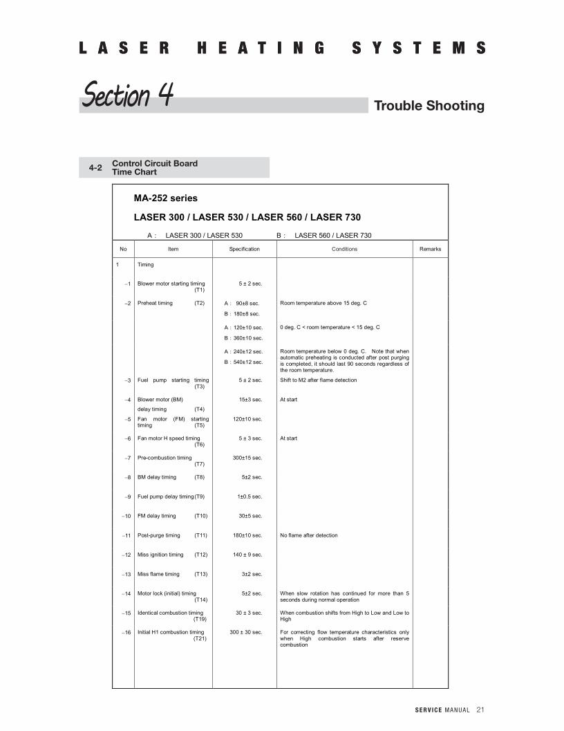
MA-252 series
LASER 300 / LASER 530 / LASER 560 / LASER 730
A: LASER 300 / LASER 530 B: LASER 560 / LASER 730
No Item Specification Conditions Remarks
1 Timing
1 Blower motor starting timing (T1)
5 ± 2 sec.
2 Preheat timing (T2) A: 90±8 sec.
B:180±8 sec.
Room temperature above 15 deg. C
A:120±10 sec.
B:360±10 sec.
0 deg. C < room temperature < 15 deg. C
A:240±12 sec.
B:540±12 sec.
Room temperature below 0 deg. C. Note that when automatic preheating is conducted after post purging is completed, it should last 90 seconds regardless of the room temperature.
3 Fuel pump starting timing (T3)
5 ± 2 sec. Shift to M2 after flame detection
4 Blower motor (BM)
delay timing (T4)
15±3 sec. At start
5 Fan motor (FM) starting timing (T5)
120±10 sec.
6 Fan motor H speed timing (T6)
5 ± 3 sec. At start
7 Pre-combustion timing (T7)
300±15 sec.
8 BM delay timing (T8) 5±2 sec.
9 Fuel pump delay timing (T9) 1±0.5 sec.
10 FM delay timing (T10) 30±5 sec.
11 Post-purge timing (T11) 180±10 sec. No flame after detection
12 Miss ignition timing (T12) 140 ± 9 sec.
13 Miss flame timing (T13) 3±2 sec.
14 Motor lock (initial) timing (T14)
5±2 sec. When slow rotation has continued for more than 5 seconds during normal operation
15 Identical combustion timing (T19)
30 ± 3 sec. When combustion shifts from High to Low and Low to High
16 Initial H1 combustion timing (T21)
300 ± 30 sec. For correcting flow temperature characteristics only when High combustion starts after reserve combustion
4-2 Control Circuit BoardTime Chart
22 S E R V I C E M A N U A L
L A S E R H E A T I N G S Y S T E M SL A S E R H E A T I N G S Y S T E M S
Trouble ShootingSection 4
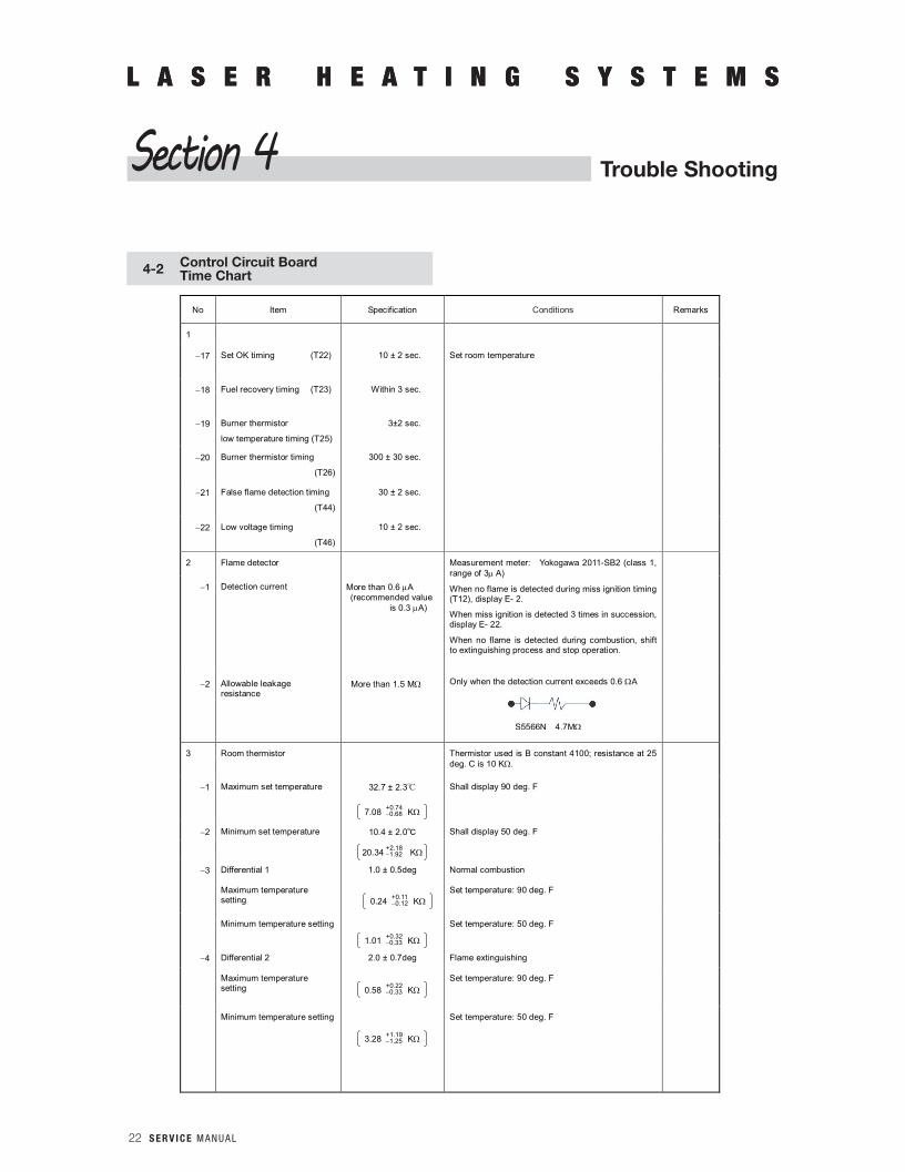
No Item Specification Conditions Remarks
1
17 Set OK timing (T22) 10 ± 2 sec. Set room temperature
18 Fuel recovery timing (T23) Within 3 sec.
19 Burner thermistor
low temperature timing (T25)
3±2 sec.
20 Burner thermistor timing
(T26)
300 ± 30 sec.
21 False flame detection timing
(T44)
30 ± 2 sec.
22 Low voltage timing
(T46)
10 ± 2 sec.
2 Flame detector Measurement meter: Yokogawa 2011-SB2 (class 1, range of 3 A)
When no flame is detected during miss ignition timing (T12), display E- 2.
When miss ignition is detected 3 times in succession, display E- 22.
When no flame is detected during combustion, shift to extinguishing process and stop operation.
Only when the detection current exceeds 0.6 A
1 Detection current More than 0.6 A (recommended value is 0.3 A)
2 Allowable leakage resistance
More than 1.5 M
3 Room thermistor Thermistor used is B constant 4100; resistance at 25 deg. C is 10 K.
1 Maximum set temperature 32.7 ± 2.3 Shall display 90 deg. F
2 Minimum set temperature 10.4 ± 2.0 Shall display 50 deg. F
3 Differential 1 1.0 ± 0.5deg Normal combustion
Maximum temperature setting
Set temperature: 90 deg. F
Minimum temperature setting Set temperature: 50 deg. F
4 Differential 2 2.0 ± 0.7deg Flame extinguishing
Maximum temperature setting
Set temperature: 90 deg. F
Minimum temperature setting Set temperature: 50 deg. F
7.08 K +0.74 0.68
20.34 K +2.18 1.92
0.24 K +0.11 0.12
1.01 K +0.32 0.33
0.58 K +0.22 0.33
3.28 K +1.19 1.25
S5566N 4.7M
4-2 Control Circuit BoardTime Chart

S E R V I C E M A N U A L 23
L A S E R H E A T I N G S Y S T E M S
4-2 Control Circuit BoardTime Chart
L A S E R H E A T I N G S Y S T E M S
Trouble ShootingSection 4
No Item Specification Conditions Remarks
3
5 Differential 3 6.0 ± 1.0deg Save flame extinguishing
Maximum temperature setting
Set temperature: 90 deg. F
Minimum temperature setting
Set temperature: 50 deg. F
6 Preheat reduction resistor 1 15.6 ± 1.9deg A: Preheat for 90 sec.
B: Preheat for 180 sec.
Preheat reduction resistor 2 0.7 ± 2.5deg A: Preheat for 120 sec.
B: Preheat for 360 sec.
7 Room thermistor combustion control (See the following diagram)
8 Initial room thermistor
combustion control (after T7 ends)
For the set temperature:
Less than –1.0 deg.
-1.0 to 0 deg.
Over 0 deg.
High combustion
Medium combustion
Low combustion
2 ± 0.7deg Flame extinguishing begins when the set temperature is exceeded by more than 2 degrees C. Operation begins again when the temperature inside the room falls below the set temperature during the flame extinguishing process.
9 Power saver operation 6 ± 1.0deg Flame extinguishing begins when the set temperature is exceeded by more than 6 degrees C. Operation begins again when the temperature inside the room falls below the set temperature during the flame extinguishing process.
1.54 K +0.31 0.30
5.46 K +0.74 0.71
15.68 K +1.58 1.42
33.85 K +4.51 3.77
Set temperature
Normal operation Save operation
+ 1.0
+ 2.0
+ 6.0
1.0
H M H M L M L OFF M L
24 S E R V I C E M A N U A L
L A S E R H E A T I N G S Y S T E M S
4-2 Control Circuit BoardTime Chart
L A S E R H E A T I N G S Y S T E M S
Trouble ShootingSection 4
No Item Specification Conditions Remarks
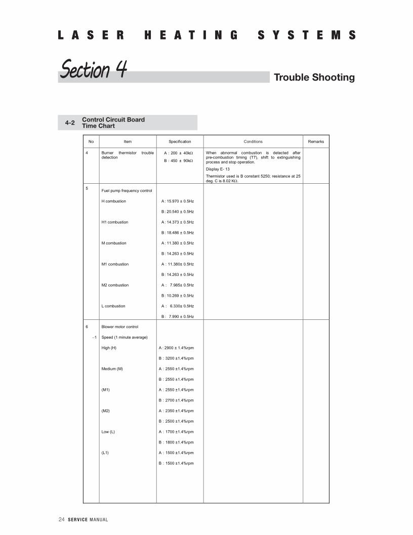
4 Burner thermistor trouble detection
A:200 ± 40k
B:450 ± 90k
When abnormal combustion is detected after pre-combustion timing (T7), shift to extinguishing process and stop operation.
Display E- 13
Thermistor used is B constant 5250; resistance at 25 deg. C is 8.02 K.
5 Fuel pump frequency control
H combustion
H1 combustion
M combustion
M1 combustion
M2 combustion
L combustion
A:15.970 ± 0.5Hz
B:20.540 ± 0.5Hz
A:14.373 ± 0.5Hz
B:18.486 ± 0.5Hz
A:11.380 ± 0.5Hz
B:14.263 ± 0.5Hz
A:11.380± 0.5Hz
B:14.263 ± 0.5Hz
A: 7.985± 0.5Hz
B:10.269 ± 0.5Hz
A: 6.330± 0.5Hz
B: 7.990 ± 0.5Hz
6
1
Blower motor control
Speed (1 minute average)
High (H)
Medium (M)
(M1)
(M2)
Low (L)
(L1)
A:2900 ± 1.4%rpm
B:3200 ±1.4%rpm
A:2550 ±1.4%rpm
B:2550 ±1.4%rpm
A:2550 ±1.4%rpm
B:2700 ±1.4%rpm
A:2350 ±1.4%rpm
B:2500 ±1.4%rpm
A:1700 ±1.4%rpm
B:1800 ±1.4%rpm
A:1500 ±1.4%rpm
B:1500 ±1.4%rpm
S E R V I C E M A N U A L 25
L A S E R H E A T I N G S Y S T E M S
4-2 Control Circuit BoardTime Chart
L A S E R H E A T I N G S Y S T E M S
Trouble ShootingSection 4
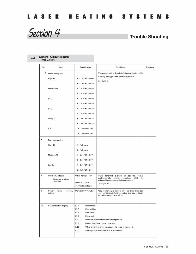
No Item Specification Conditions Remarks
2 Motor lock speed
High (H)
Medium (M)
(M1)
(M2)
Low (L)
(L1)
A:1144 ±1.4%rpm
B:1259 ±1.4%rpm
A:1030 ±1.4%rpm
B:1030 ±1.4%rpm
A:1030 ±1.4%rpm
B:1030 ±1.4%rpm
A:1030 ±1.4%rpm
B:1030 ±1.4%rpm
A: 687 ±1.4%rpm
B: 687 ±1.4%rpm
A: not detected
B: not detected
When motor lock is detected during combustion, shift
to extinguishing process and stop operation.
Display E- 8.
7 Fan motor control
High (H)
Medium (M)
Low (L)
A:Full wave
B:Full wave
A:5 : 1 (ON : OFF)
B:3 : 1 (ON : OFF)
A:2 : 1 (ON : OFF)
B:1 : 3 (ON : OFF)
8 Overheat protector
Abnormal overheat detection
When normal ON
When abnormal
overheat is detected
When abnormal overheat is detected during electromagnetic pump operation, shift to extinguishing process and stop operation.
Display E- 12.
9 Power failure recovery system
More than 30 minutes Keep in memory of current time, set timer time, set room temperature, timer operation and power saver operation during power failure.
10 Segment safety display E- 0 Power failure
E- 2 Miss ignition
E- 6 Miss flame
E- 8 Motor lock
E-12 Recovery after overheat protector operated
E-13 Burner thermistor trouble detection
E-22 When an ignition error has occurred 3 times in succession
E-23 Primary flame (Flame sensor) is malfunction
26 S E R V I C E M A N U A L
L A S E R H E A T I N G S Y S T E M S
4-2 Control Circuit BoardTime Chart
L A S E R H E A T I N G S Y S T E M S
Trouble ShootingSection 4
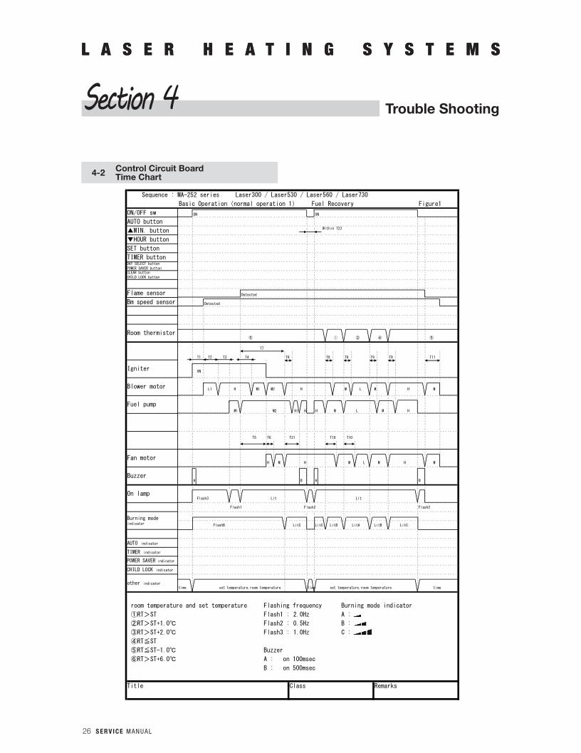
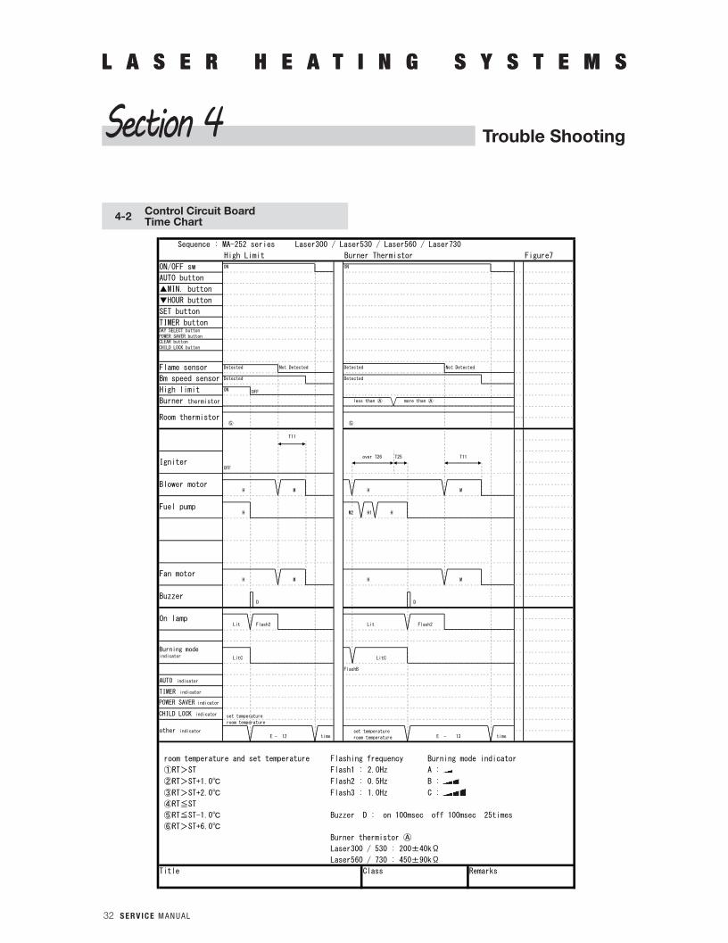
Sequence : MA-252 series Laser300 / Laser530 / Laser560 / Laser730
Basic Operation(normal operation 1) Fuel Recovery Figure1
ON/OFF sw ON ON
AUTO button
MIN. button Within T23
HOUR button
SET button
TIMER button
Flame sensor Detected
Bm speed sensor Detected
⑤ ① ② ④ ⑤
T7
T1 T2 T3 T4 T9 T8 T8 T9 T9 T11
ON
L1 H M1 M2 H M L M H M
M1 M2 H1 H H M L M H
T5 T6 T21 T10 T10
H M H M L M H M
A B A B
Flash3 Lit Lit
Flash1 Flash2 Flash2
FlashB LitC LitC LitB LitA LitB LitC
time set temperature,room temperature time set temperature,room temperature time
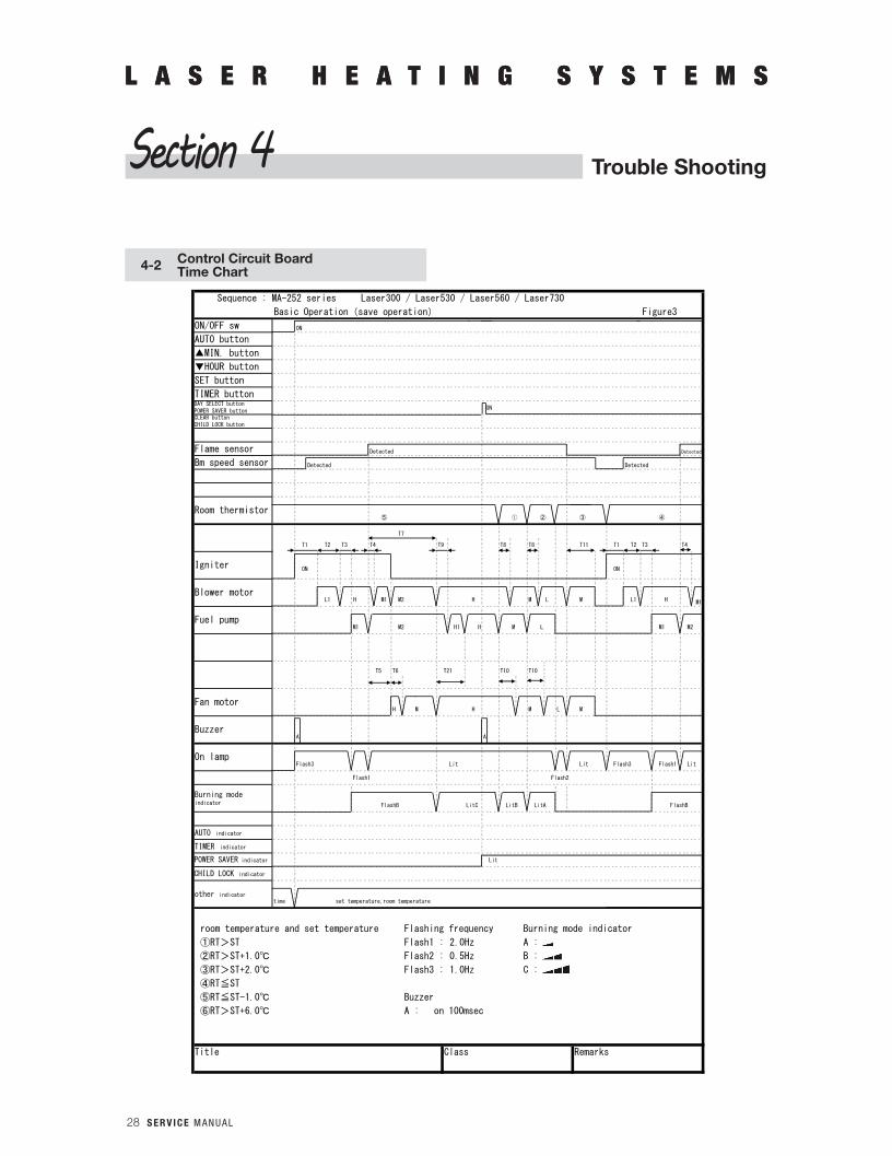
room temperature and set temperature Flashing frequency Burning mode indicator
①RT>ST Flash1 : 2.0Hz A :
②RT>ST+1.0 Flash2 : 0.5Hz B :
③RT>ST+2.0 Flash3 : 1.0Hz C :
④RT≦ST
⑤RT≦ST-1.0 Buzzer
⑥RT>ST+6.0 A : on 100msec
B : on 500msec
Title Class Remarks
Burning modeindicator
On lamp
CHILD LOCK indicator
Room thermistor
DAY SELECT buttonPOWER SAVER buttonCLEAR buttonCHILD LOCK button
Igniter
Blower motor
Fuel pump
Fan motor
Buzzer
AUTO indicator
TIMER indicator
other indicator
POWER SAVER indicator
S E R V I C E M A N U A L 27
L A S E R H E A T I N G S Y S T E M S
4-2 Control Circuit BoardTime Chart
L A S E R H E A T I N G S Y S T E M S
Trouble ShootingSection 4
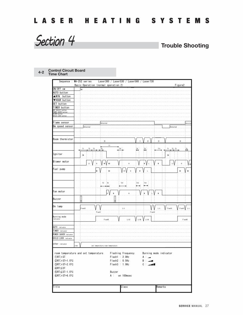
Sequence : MA-252 series Laser300 / Laser530 / Laser560 / Laser730
Basic Operation(normal operation 2) Figure2
ON/OFF sw ON
AUTO button
MIN. button
HOUR button
SET button
TIMER button
Flame sensor Detected Detected
Bm speed sensor Detected Detected
⑤ ① ② ③ ④
T7
T1 T2 T3 T4 T9 T8 T8 T11 T1 T2 T3 T4
ON ON
L1 H M1 M2 H M L M L1 H M1
M1 M2 H1 H M L M1 M2
T5 T6 T21 T10 T10
H M H M L M
A A
Flash3 Lit Lit Flash3 Flash1 Lit
Flash1 Flash2
FlashB LitC LitB LitA FlashB
time set temperature,room temperature
room temperature and set temperature Flashing frequency Burning mode indicator
①RT>ST Flash1 : 2.0Hz A :
②RT>ST+1.0 Flash2 : 0.5Hz B :
③RT>ST+2.0 Flash3 : 1.0Hz C :
④RT≦ST
⑤RT≦ST-1.0 Buzzer
⑥RT>ST+6.0 A : on 100msec
Title Class Remarks
DAY SELECT buttonPOWER SAVER buttonCLEAR buttonCHILD LOCK button
On lamp
Burning modeindicator
POWER SAVER indicator
CHILD LOCK indicator
Blower motor
Fuel pump
Igniter
Buzzer
Room thermistor
Fan motor
AUTO indicator
TIMER indicator
other indicator
28 S E R V I C E M A N U A L
L A S E R H E A T I N G S Y S T E M S
4-2 Control Circuit BoardTime Chart
Sequence : MA-252 series Laser300 / Laser530 / Laser560 / Laser730
Basic Operation(save operation) Figure3
ON/OFF sw ON
AUTO button
MIN. button
HOUR button
SET button
TIMER button
ON
Flame sensor Detected Detected
Bm speed sensor Detected Detected
⑤ ① ② ③ ④
T7
T1 T2 T3 T4 T9 T8 T8 T11 T1 T2 T3 T4
ON ON
L1 H M1 M2 H M L M L1 H M1
M1 M2 H1 H M L M1 M2
T5 T6 T21 T10 T10
H M H M L M
A A
Flash3 Lit Lit Flash3 Flash1 Lit
Flash1 Flash2
FlashB LitC LitB LitA FlashB
Lit
time set temperature,room temperature
room temperature and set temperature Flashing frequency Burning mode indicator
①RT>ST Flash1 : 2.0Hz A :
②RT>ST+1.0 Flash2 : 0.5Hz B :
③RT>ST+2.0 Flash3 : 1.0Hz C :
④RT≦ST
⑤RT≦ST-1.0 Buzzer
⑥RT>ST+6.0 A : on 100msec
Title Class Remarks
other indicator
Burning modeindicator
AUTO indicator
TIMER indicator
POWER SAVER indicator
CHILD LOCK indicator
Blower motor
Fuel pump
Fan motor
Buzzer
On lamp
DAY SELECT buttonPOWER SAVER buttonCLEAR buttonCHILD LOCK button
Room thermistor
Igniter
L A S E R H E A T I N G S Y S T E M S
Trouble ShootingSection 4
S E R V I C E M A N U A L 29
L A S E R H E A T I N G S Y S T E M S
4-2 Control Circuit BoardTime Chart
L A S E R H E A T I N G S Y S T E M S
Trouble ShootingSection 4
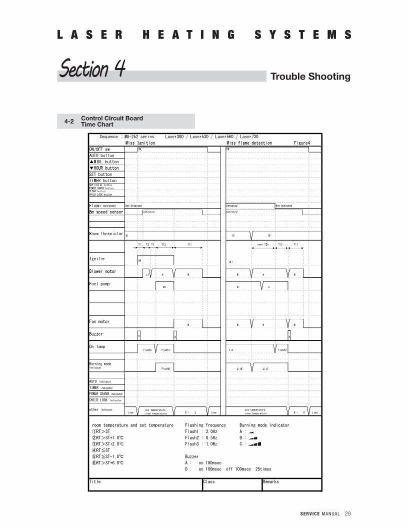
Sequence : MA-252 series Laser300 / Laser530 / Laser560 / Laser730
Miss Ignition Miss flame detection Figure4
ON/OFF sw ON ON
AUTO button
MIN. button
HOUR button
SET button
TIMER button
Flame sensor Not Detected Detected Not Detected
Bm speed sensor Detected Detected
⑤ ④ ⑤
T1 T2 T3 T12 T11 over T24 T13 T11
ONOFF
L1 H M M H M
M1 M H
M M H M
AD D
Flash3 Flash1 Lit Flash2
FlashB LitB LitC
time E - 2 time E - 6 time
room temperature and set temperature Flashing frequency Burning mode indicator
①RT>ST Flash1 : 2.0Hz A :
②RT>ST+1.0 Flash2 : 0.5Hz B :
③RT>ST+2.0 Flash3 : 1.0Hz C :
④RT≦ST
⑤RT≦ST-1.0 Buzzer
⑥RT>ST+6.0 A : on 100msec
D : on 100msec off 100msec 25times
Title Class Remarks
Burning modeindicator
Fuel pump
AUTO indicator
TIMER indicator
other indicator
POWER SAVER indicator
CHILD LOCK indicator
Fan motor
Buzzer
CLEAR buttonCHILD LOCK button
DAY SELECT buttonPOWER SAVER button
Room thermistor
Igniter
Blower motor
On lamp
set temperature
room temperature
set temperature
room temperature
30 S E R V I C E M A N U A L
L A S E R H E A T I N G S Y S T E M S
4-2 Control Circuit BoardTime Chart
L A S E R H E A T I N G S Y S T E M S
Trouble ShootingSection 4
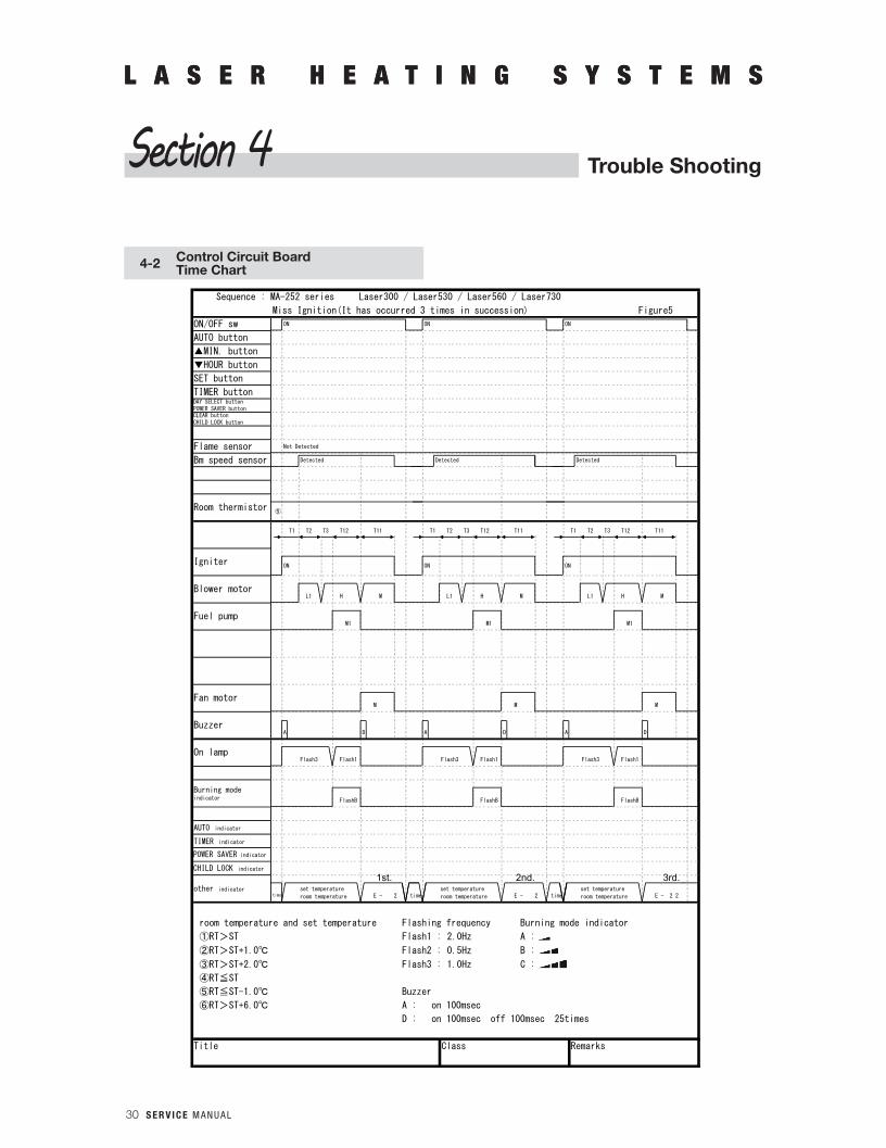
Sequence : MA-252 series Laser300 / Laser530 / Laser560 / Laser730
Miss Ignition(It has occurred 3 times in succession) Figure5
ON/OFF sw ON ON ON
AUTO button
MIN. button
HOUR button
SET button
TIMER button
Flame sensor Not Detected
Bm speed sensor Detected Detected Detected
⑤
T1 T2 T3 T12 T11 T1 T2 T3 T12 T11 T1 T2 T3 T12 T11
ON ON ON
L1 H M L1 H M L1 H M
M1 M1 M1
M M M
A D A D A D
Flash3 Flash1 Flash3 Flash1 Flash3 Flash1
FlashB FlashB FlashB
E - 2 time E - 2 time E - 2 2
room temperature and set temperature Flashing frequency Burning mode indicator
①RT>ST Flash1 : 2.0Hz A :
②RT>ST+1.0 Flash2 : 0.5Hz B :
③RT>ST+2.0 Flash3 : 1.0Hz C :
④RT≦ST
⑤RT≦ST-1.0 Buzzer
⑥RT>ST+6.0 A : on 100msec
D : on 100msec off 100msec 25times
Title Class Remarks
AUTO indicator
TIMER indicator
other indicatortime
POWER SAVER indicator
CHILD LOCK indicator
Fan motor
Room thermistor
Buzzer
On lamp
DAY SELECT buttonPOWER SAVER buttonCLEAR buttonCHILD LOCK button
Burning modeindicator
Igniter
Blower motor
Fuel pump
set temperature
room temperature
set temperature
room temperature
set temperature
room temperature
1st. 2nd. 3rd.
S E R V I C E M A N U A L 31
L A S E R H E A T I N G S Y S T E M S
4-2 Control Circuit BoardTime Chart
L A S E R H E A T I N G S Y S T E M S
Trouble ShootingSection 4
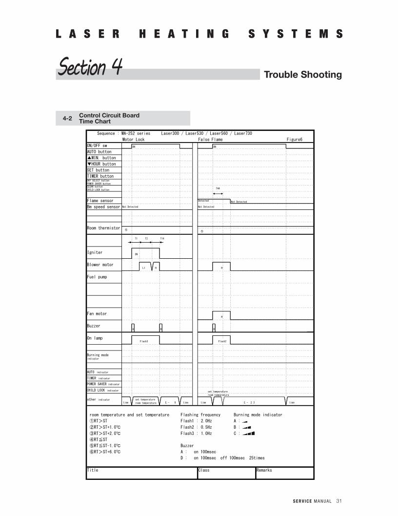
Sequence : MA-252 series Laser300 / Laser530 / Laser560 / Laser730
Motor Lock False Flame Figure6
ON/OFF sw ON ON
AUTO button
MIN. button
HOUR button
SET button
TIMER button
T44
Flame sensor Detected Not Detected
Bm speed sensor Not Detected Not Detected
⑤⑤
T1 T2 T14
ON
L1 H H
H
A D D
Flash3 Flash2
time E - 8 time time E - 2 3 time
room temperature and set temperature Flashing frequency Burning mode indicator
①RT>ST Flash1 : 2.0Hz A :
②RT>ST+1.0 Flash2 : 0.5Hz B :
③RT>ST+2.0 Flash3 : 1.0Hz C :
④RT≦ST
⑤RT≦ST-1.0 Buzzer
⑥RT>ST+6.0 A : on 100msec
D : on 100msec off 100msec 25times
Title Class Remarks
AUTO indicator
Fuel pump
Fan motor
Buzzer
Blower motor
TIMER indicator
other indicator
POWER SAVER indicator
CHILD LOCK indicator
On lamp
Burning modeindicator
Room thermistor
Igniter
DAY SELECT buttonPOWER SAVER buttonCLEAR buttonCHILD LOCK button
set temperature
room temperature
set temperature
room temperature
32 S E R V I C E M A N U A L
L A S E R H E A T I N G S Y S T E M S
4-2 Control Circuit BoardTime Chart
L A S E R H E A T I N G S Y S T E M S
Trouble ShootingSection 4
Sequence : MA-252 series Laser300 / Laser530 / Laser560 / Laser730
High Limit Burner Thermistor Figure7
ON/OFF sw ON ON
AUTO button
MIN. button
HOUR button
SET button
TIMER button
Flame sensor Detected Not Detected Detected Not Detected
Bm speed sensor Detected Detected
High limit ON OFF
Burner thermistor less than more than
⑤ ⑤
T11
over T26 T25 T11
OFF
H M H M
H M2 H1 H
H M H M
D D
Lit Flash2 Lit Flash2
LitC LitC
FlashB
E - 12 time E - 13 time
room temperature and set temperature Flashing frequency Burning mode indicator
①RT>ST Flash1 : 2.0Hz A :
②RT>ST+1.0 Flash2 : 0.5Hz B :
③RT>ST+2.0 Flash3 : 1.0Hz C :
④RT≦ST
⑤RT≦ST-1.0 Buzzer D : on 100msec off 100msec 25times
⑥RT>ST+6.0
Burner thermistor
Laser300 / 530 : 200±40kΩ
Laser560 / 730 : 450±90kΩ
Title Class Remarks
Blower motor
Fuel pump
TIMER indicator
Room thermistor
Igniter
DAY SELECT buttonPOWER SAVER buttonCLEAR buttonCHILD LOCK button
other indicator
POWER SAVER indicator
CHILD LOCK indicator
Fan motor
Buzzer
On lamp
Burning modeindicator
AUTO indicator
set temperature
room temperature
set temperature
room temperature
S E R V I C E M A N U A L 33
Blower motor malfunction or blowerfan touches to obstruction
Check or replace blower motor orblower motor case
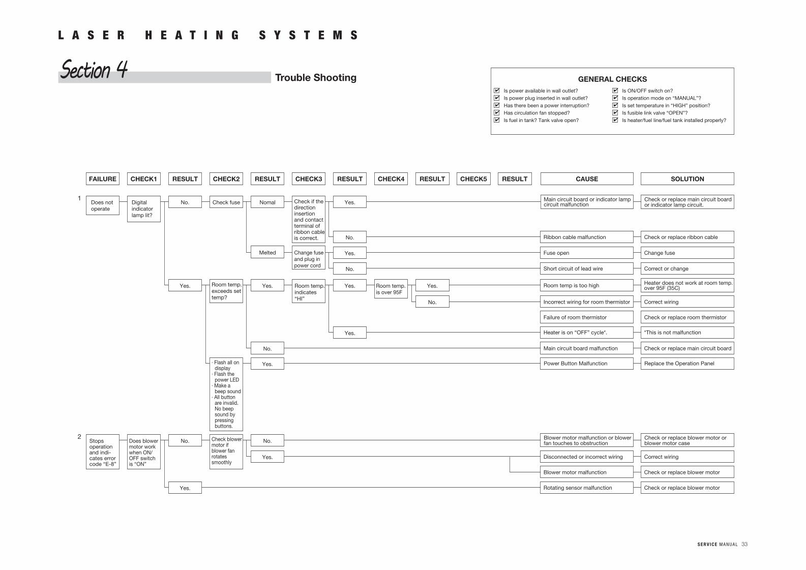
Is power available in wall outlet?Is power plug inserted in wall outlet?Has there been a power interruption?Has circulation fan stopped?Is fuel in tank? Tank valve open?
Is ON/OFF switch on?Is operation mode on “MANUAL”?Is set temperature in “HIGH” position?Is fusible link valve “OPEN”?Is heater/fuel line/fuel tank installed properly?
GENERAL CHECKS
SOLUTIONCAUSERESULTCHECK5RESULTCHECK4RESULTCHECK3RESULTCHECK2RESULTCHECK1FAILURE
Check or replace main circuit boardor indicator lamp circuit.
Main circuit board or indicator lamp circuit malfunction
Check or replace ribbon cableRibbon cable malfunction
Change fuseFuse open
Correct or changeShort circuit of lead wire
Correct wiringIncorrect wiring for room thermistor
Heater does not work at room temp.over 95F (35C)Room temp is too high
Yes.
No.
Yes.
No.
Check if thedirectioninsertionand contactterminal ofribbon cableis correct.
Nomal
Change fuseand plug inpower cord
Melted
Check fuse
Room temp.exceeds settemp?
No.
Yes.
No.
Room temp.is over 95F
Yes.
Yes.
Room temp.indicates“HI”
Yes.Yes.
Digitalindicatorlamp lit?
Does notoperate
1
2No.
No.
Yes.
Check blowermotor ifblower fanrotatessmoothly
Yes.· Flash all ondisplay
· Flash thepower LED
· Make abeep sound
· All buttonare invalid.No beepsound bypressingbuttons.
No.
Check or replace room thermistorFailure of room thermistor
Check or replace main circuit boardMain circuit board malfunction
*This is not malfunctionHeater is on “OFF” cycle*.
Correct wiringDisconnected or incorrect wiring
Check or replace blower motorBlower motor malfunction
Check or replace blower motorRotating sensor malfunctionYes.
Does blowermotor workwhen ON/OFF switchis “ON”
Stopsoperationand indi-cates errorcode “E-8”
Power Button Malfunction Replace the Operation Panel
L A S E R H E A T I N G S Y S T E M S
Trouble ShootingSection 4
S E R V I C E M A N U A L 34
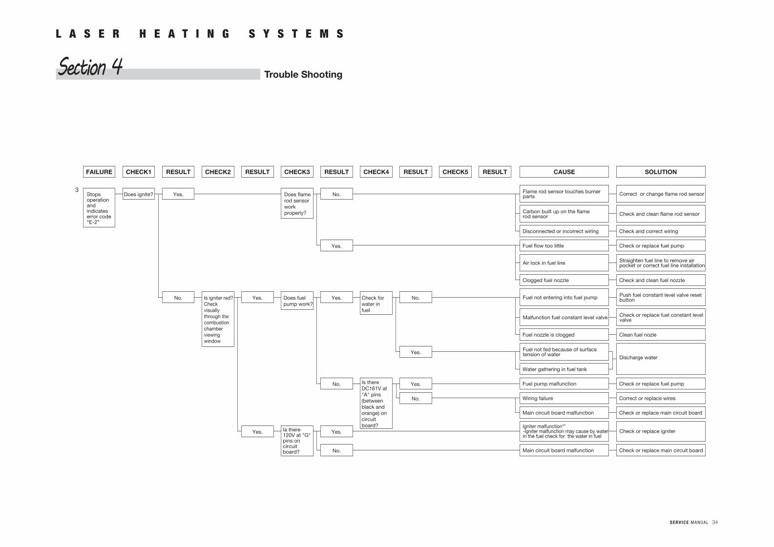
SOLUTIONCAUSERESULTCHECK5RESULTCHECK4RESULTCHECK3RESULTCHECK2RESULTCHECK1
Correct or change flame rod sensorFlame rod sensor touches burnerparts
Check and clean flame rod sensorCarbon built up on the flamerod sensor
Air lock in fuel line Straighten fuel line to remove airpocket or correct fuel line installation
Fuel not entering into fuel pump Push fuel constant level valve resetbutton
Malfunction fuel constant level valve Check or replace fuel constant levelvalve
Discharge water
Fuel not fed because of surfacetension of water
Check or replace igniterlgniter malfunction**-lgniter malfunction may cause by water in the fuel check for the water in fuel
Check and correct wiringDisconnected or incorrect wiring
Check and clean fuel nozzleClogged fuel nozzle
Clean fuel nozleFuel nozzle is clogged
Check or replace fuel pumpFuel pump malfunction
Correct or replace wiresWiring failure
Check or replace main circuit boardMain circuit board malfunction
Check or replace main circuit boardMain circuit board malfunction
Water gathering in fuel tank
Check or replace fuel pumpFuel flow too little
No.
Yes.
Does flamerod sensorworkproperly?
Is igniter red?Checkvisuallythrough thecombustionchamberviewingwindow
Yes.
No.
Yes.
Yes.
No.
Check forwater infuel
Is thereDC161V at"A" pins(betweenblack andorange) oncircuitboard?
Yes.
No.
Yes.
No.
Does fuelpump work?
Yes.
Yes.
No.
Does ignite?Stopsoperationandindicateserror code“E-2”
Ia there120V at "G"pins on circuitboard?
FAILURE
3
L A S E R H E A T I N G S Y S T E M S
Trouble ShootingSection 4
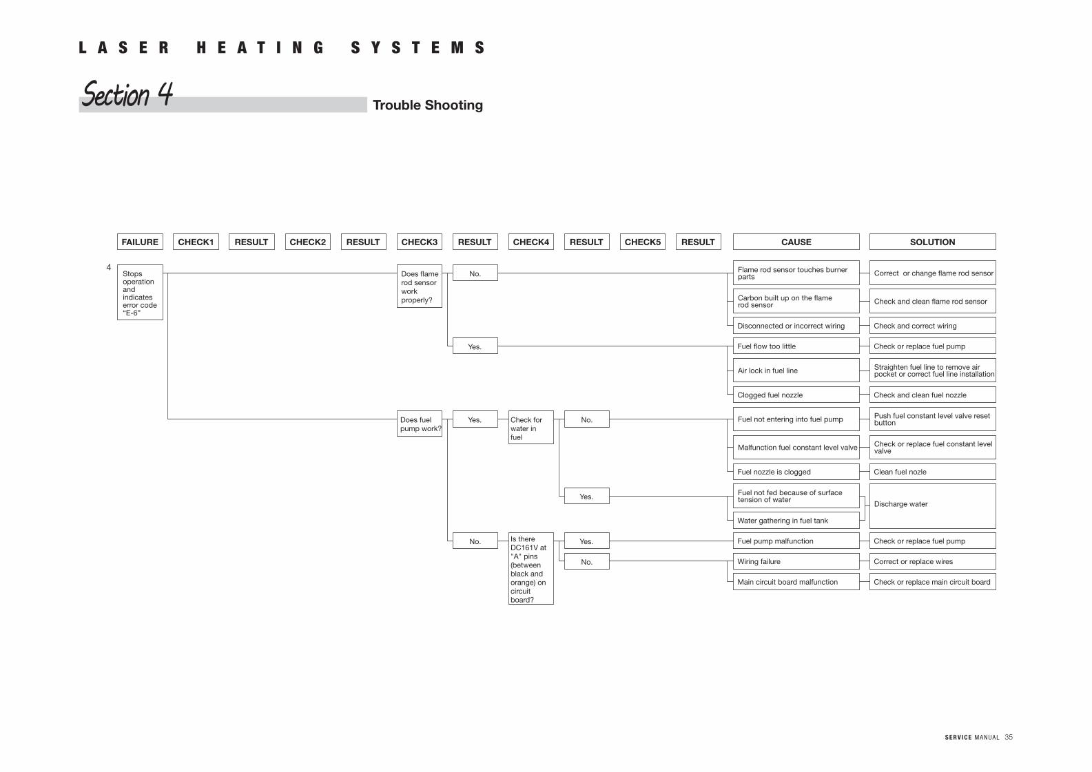
S E R V I C E M A N U A L 35
SOLUTIONCAUSERESULTCHECK5RESULTCHECK4RESULTCHECK3RESULTCHECK2RESULTCHECK1
Correct or change flame rod sensorFlame rod sensor touches burnerparts
Check and clean flame rod sensorCarbon built up on the flamerod sensor
Air lock in fuel line Straighten fuel line to remove airpocket or correct fuel line installation
Fuel not entering into fuel pump Push fuel constant level valve resetbutton
Malfunction fuel constant level valve Check or replace fuel constant levelvalve
Discharge water
Fuel not fed because of surfacetension of water
Check and correct wiringDisconnected or incorrect wiring
Check and clean fuel nozzleClogged fuel nozzle
Clean fuel nozleFuel nozzle is clogged
Check or replace fuel pumpFuel pump malfunction
Correct or replace wiresWiring failure
Check or replace main circuit boardMain circuit board malfunction
Water gathering in fuel tank
Check or replace fuel pumpFuel flow too little
No.
Yes.
Does flamerod sensorworkproperly?
No.
Yes.
Yes.
No.
Check forwater infuel
Is thereDC161V at"A" pins(betweenblack andorange) oncircuitboard?
Yes.
No.
Does fuelpump work?
Stopsoperationandindicateserror code“E-6”
FAILURE
4
L A S E R H E A T I N G S Y S T E M S
Trouble ShootingSection 4
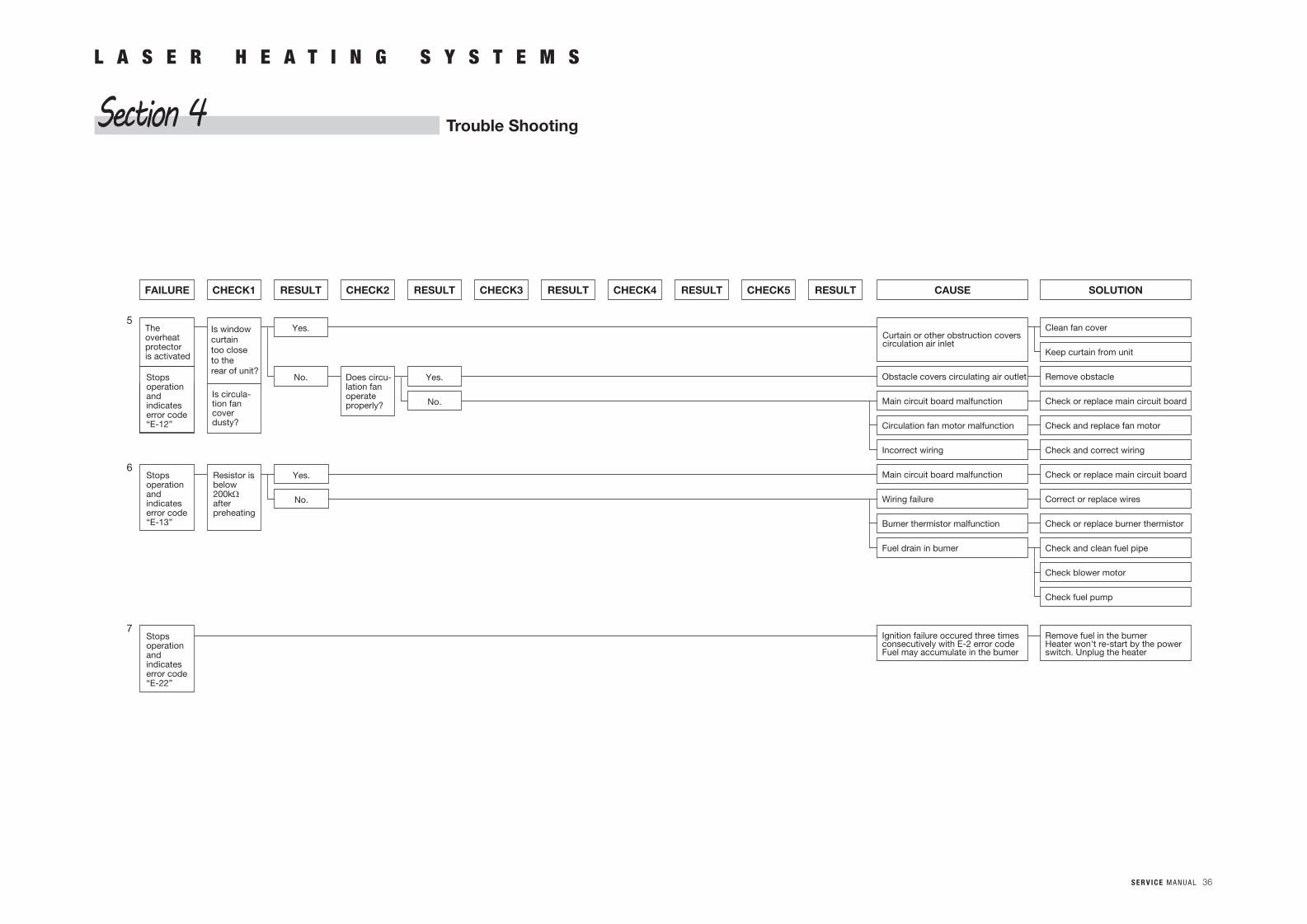
S E R V I C E M A N U A L 36
SOLUTIONCAUSERESULTCHECK5RESULTCHECK4RESULTCHECK3RESULTCHECK2RESULTCHECK1
Curtain or other obstruction coverscirculation air inlet
Remove obstacleObstacle covers circulating air outlet
Check and replace fan motorCirculation fan motor malfunction
Check and correct wiringIncorrect wiring
Check or replace main circuit board
Clean fan cover
Keep curtain from unit
Main circuit board malfunction
Check or replace main circuit boardMain circuit board malfunction
Check or replace burner thermistorBumer thermistor malfunction
Check and clean fuel pipe
Check blower motor
Check fuel pump
Fuel drain in bumer
Remove fuel in the burnerHeater won't re-start by the powerswitch. Unplug the heater
Ignition failure occured three timesconsecutively with E-2 error codeFuel may accumulate in the bumer
Correct or replace wiresWiring failure
Yes.
No.
Yes.
No.
Yes.
No.
Is windowcurtaintoo closeto therear of unit?
Theoverheatprotectoris activated
Is circula-tion fancoverdusty?
Does circu-lation fanoperateproperly?
Resistor isbelow200kΩafterpreheating
Stopsoperationandindicateserror code“E-13”
Stopsoperationandindicateserror code“E-12”
Stopsoperationandindicateserror code“E-22”
FAILURE
5
6
7
L A S E R H E A T I N G S Y S T E M S
Trouble ShootingSection 4
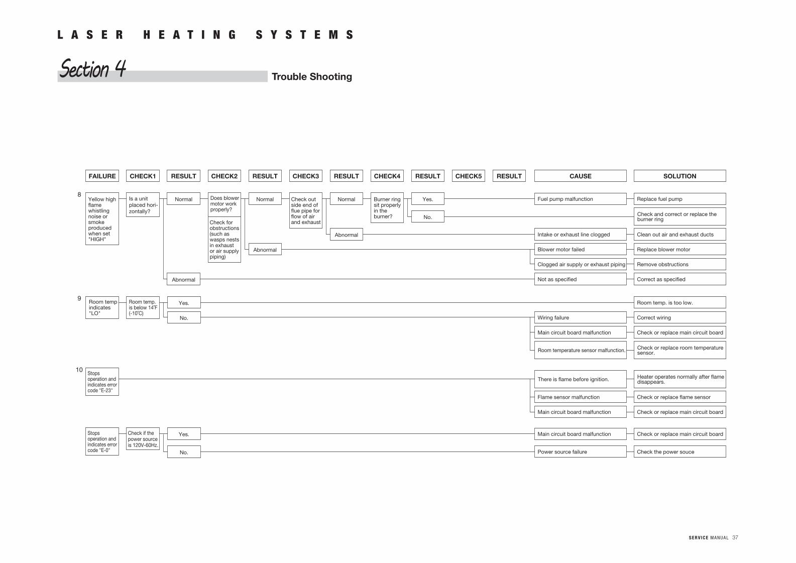
S E R V I C E M A N U A L 37
L A S E R H E A T I N G S Y S T E M S
Trouble ShootingSection 4
SOLUTIONCAUSERESULTCHECK5RESULTCHECK4RESULTCHECK3RESULTCHECK2RESULTCHECK1
Clean out air and exhaust ductsIntake or exhaust line clogged
Remove obstructionsClogged air supply or exhaust piping
Correct as specifiedNot as specified
Replace blower motor
Replace fuel pumpFuel pump malfunction
Blower motor failed
Correct wiringWiring failure
Check or replace main circuit boardMain circuit board malfunction
Check or replace main circuit boardMain circuit board malfunction
Check or replace flame sensorFlame sensor malfunction
Room temp. is too low.
Normal
Abnormal
Normal
Abnormal
Yes.
No.
Is a unitplaced hori-zontally?
Room temp.is below 14˚F(-10˚C)
Yes.
No.
Check if thepower sourceis 120V-60Hz.
Room tempindicates"LO"
Yellow highflamewhistlingnoise orsmokeproducedwhen set"HIGH"
Does blowermotor workproperly?
Check outside end offlue pipe forflow of airand exhaust
Normal
Abnormal
Yes.
No.
Burner ringsit properlyin theburner?
Check forobstructions(such aswasps nestsin exhaustor air supplypiping)
Stopsoperation andindicates errorcode "E-23"
FAILURE
8
9
10
Check and correct or replace theburner ring
Check or replace room temperaturesensor.Room temperature sensor malfunction.
Heater operates normally after flamedisappears.There is flame before ignition.
Check or replace main circuit boardMain circuit board malfunction
Check the power soucePower source failure
Stopsoperation andindicates errorcode "E-0"
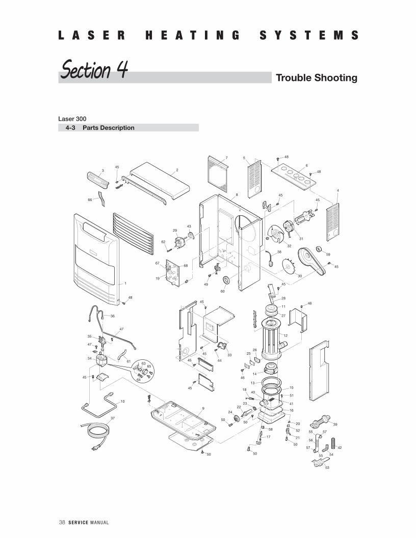
38 S E R V I C E M A N U A L
L A S E R H E A T I N G S Y S T E M SL A S E R H E A T I N G S Y S T E M S
Trouble ShootingSection 4
2
7
45
45
45
45
60
19
33
28
45
11
27
12
37
2625
4614
15
41
16
13
50
58
18
23
40
2224
5050
9
50
17
3
668
30
59
32
38
45
6
48
4
5
31
45
45
29
6768
20
21
50
52
39
42
57
54
55
55
53
56
57
1
48
36
61 6365
6445
10
34
47
35
43
45
51
48
46
49
62
47
44
Laser 3004-3 Parts Description
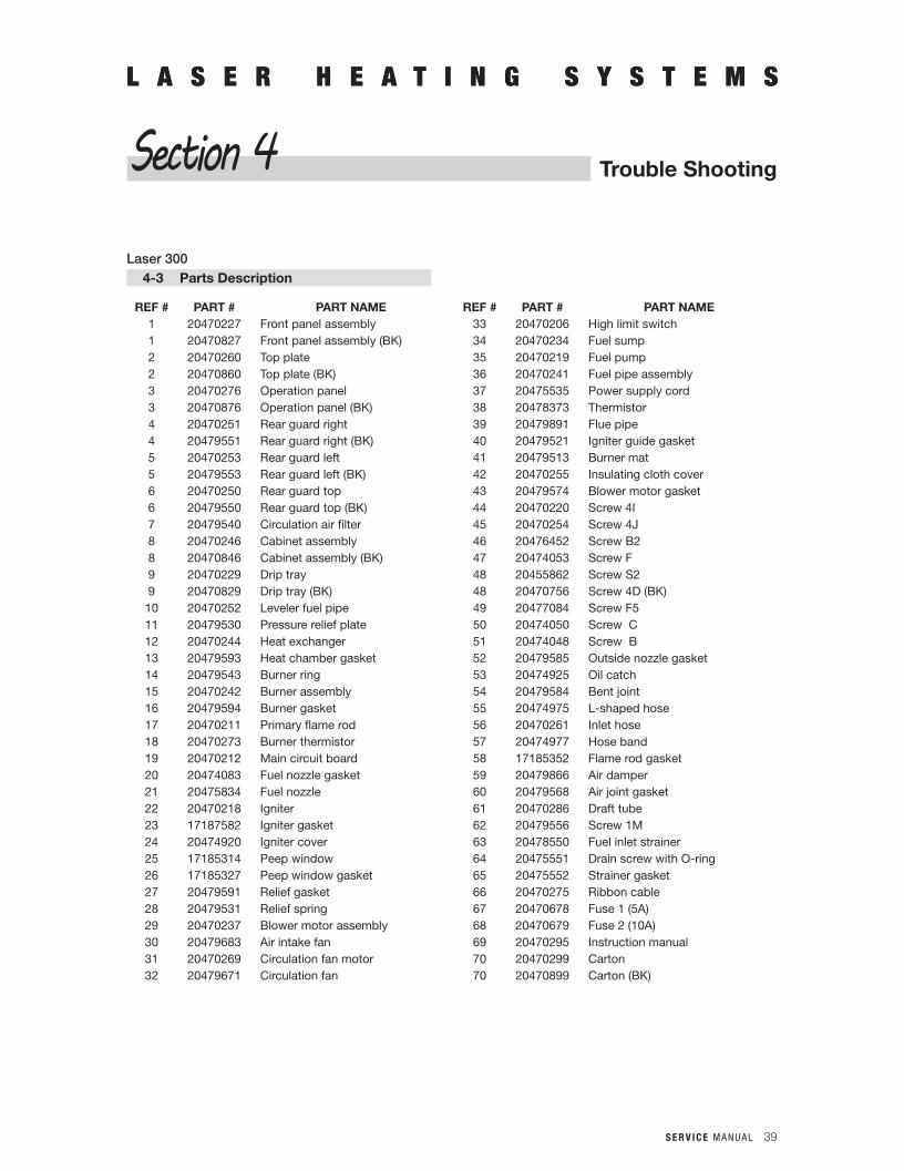
S E R V I C E M A N U A L 39
L A S E R H E A T I N G S Y S T E M SL A S E R H E A T I N G S Y S T E M S
Trouble ShootingSection 4
Laser 3004-3 Parts Description
REF # PART # PART NAME REF # PART # PART NAME1 20470227 Front panel assembly 33 20470206 High limit switch1 20470827 Front panel assembly (BK) 34 20470234 Fuel sump2 20470260 Top plate 35 20470219 Fuel pump2 20470860 Top plate (BK) 36 20470241 Fuel pipe assembly3 20470276 Operation panel 37 20475535 Power supply cord3 20470876 Operation panel (BK) 38 20478373 Thermistor4 20470251 Rear guard right 39 20479891 Flue pipe4 20479551 Rear guard right (BK) 40 20479521 Igniter guide gasket5 20470253 Rear guard left 41 20479513 Burner mat5 20479553 Rear guard left (BK) 42 20470255 Insulating cloth cover6 20470250 Rear guard top 43 20479574 Blower motor gasket6 20479550 Rear guard top (BK) 44 20470220 Screw 4I7 20479540 Circulation air filter 45 20470254 Screw 4J8 20470246 Cabinet assembly 46 20476452 Screw B28 20470846 Cabinet assembly (BK) 47 20474053 Screw F9 20470229 Drip tray 48 20455862 Screw S29 20470829 Drip tray (BK) 48 20470756 Screw 4D (BK)10 20470252 Leveler fuel pipe 49 20477084 Screw F511 20479530 Pressure relief plate 50 20474050 Screw C12 20470244 Heat exchanger 51 20474048 Screw B13 20479593 Heat chamber gasket 52 20479585 Outside nozzle gasket14 20479543 Burner ring 53 20474925 Oil catch15 20470242 Burner assembly 54 20479584 Bent joint16 20479594 Burner gasket 55 20474975 L-shaped hose17 20470211 Primary flame rod 56 20470261 Inlet hose18 20470273 Burner thermistor 57 20474977 Hose band19 20470212 Main circuit board 58 17185352 Flame rod gasket20 20474083 Fuel nozzle gasket 59 20479866 Air damper21 20475834 Fuel nozzle 60 20479568 Air joint gasket22 20470218 Igniter 61 20470286 Draft tube23 17187582 Igniter gasket 62 20479556 Screw 1M24 20474920 Igniter cover 63 20478550 Fuel inlet strainer25 17185314 Peep window 64 20475551 Drain screw with O-ring26 17185327 Peep window gasket 65 20475552 Strainer gasket27 20479591 Relief gasket 66 20470275 Ribbon cable28 20479531 Relief spring 67 20470678 Fuse 1 (5A)29 20470237 Blower motor assembly 68 20470679 Fuse 2 (10A)30 20479683 Air intake fan 69 20470295 Instruction manual31 20470269 Circulation fan motor 70 20470299 Carton32 20479671 Circulation fan 70 20470899 Carton (BK)
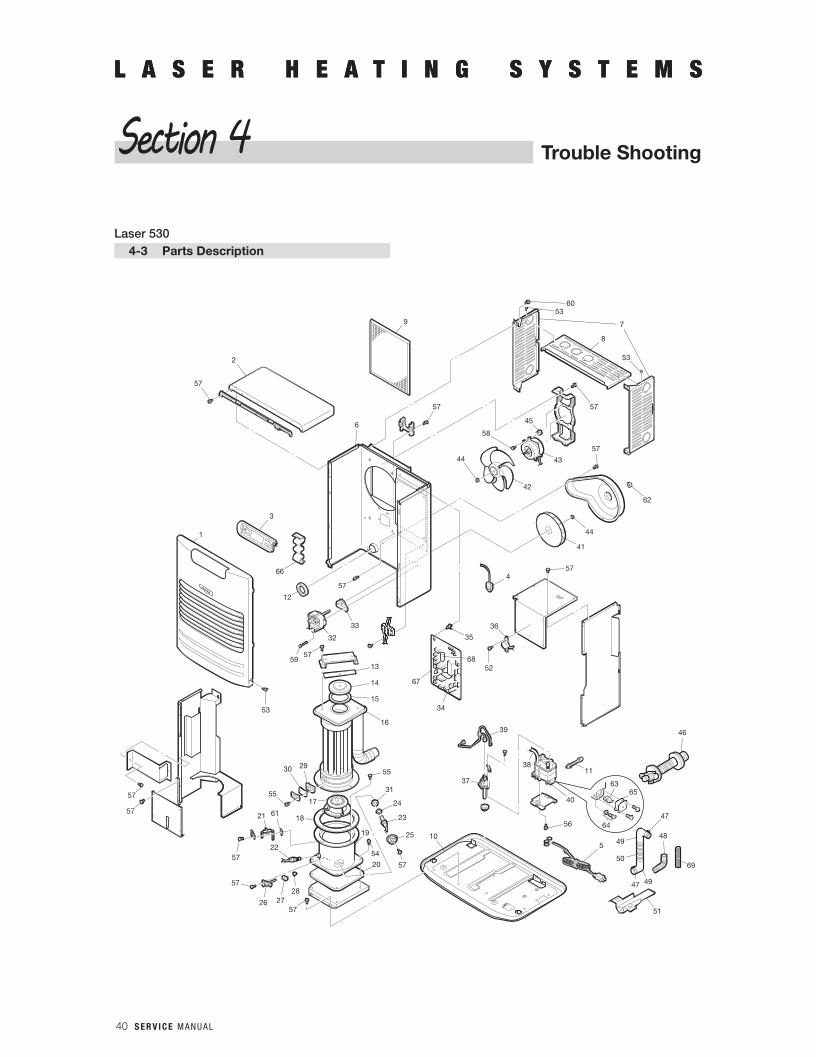
40 S E R V I C E M A N U A L
L A S E R H E A T I N G S Y S T E M SL A S E R H E A T I N G S Y S T E M S
Trouble ShootingSection 4
2
57
44
58
57
6
4
41
44
62
57
42
43
57
45
57
35
34
67
36
52
40
1138
39
37
56
5
50
48
47
46
47 49
49
51
20
24
31
23
25
57
10
29
55
30
17
18
19
5422
2827
5726
57
57
21 61
55
33
32
59
53
57
13
14
15
16
3
66
1
12
57
57
57
8
53
5360
79
6365
64
68
69
Laser 5304-3 Parts Description
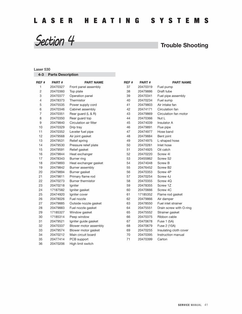
S E R V I C E M A N U A L 41
L A S E R H E A T I N G S Y S T E M SL A S E R H E A T I N G S Y S T E M S
Section 4
Laser 5304-3 Parts Description
REF # PART # PART NAME REF # PART # PART NAME1 20470327 Front panel assembly 37 20470319 Fuel pump2 20470360 Top plate 38 20479886 Draft tube3 20470377 Operation panel 39 20470341 Fuel pipe assembly4 20478373 Thermistor 40 20470234 Fuel sump5 20475535 Power supply cord 41 20479803 Air intake fan6 20470346 Cabinet assembly 42 20474171 Circulation fan7 20470351 Rear guard (L & R) 43 20479869 Circulation fan motor8 20470350 Rear guard top 44 20470366 Nut L9 20479840 Circulation air filter 45 20474039 Insulator A10 20470329 Drip tray 46 20479891 Flue pipe11 20470352 Leveler fuel pipe 47 20474977 Hose band12 20479568 Air joint gasket 48 20479884 Bent joint13 20479531 Relief spring 49 20474975 L-shaped hose14 20479530 Pressure relief plate 50 20470261 Inlet hose15 20479591 Relief gasket 51 20474925 Oil catch16 20479844 Heat exchanger 52 20470220 Screw 4I17 20478343 Burner ring 53 20455862 Screw S218 20479893 Heat exchanger gasket 54 20474048 Screw B19 20479842 Burner assembly 55 20476452 Screw B220 20479894 Burner gasket 56 20470353 Screw 4P21 20479811 Primary flame rod 57 20470254 Screw 4J22 20470273 Burner thermistor 58 20470355 Screw 4Q23 20470218 Igniter 59 20478355 Screw 1Z24 17187582 Igniter gasket 60 20470666 Screw 4C25 20474920 Igniter cover 61 17185352 Flame rod gasket26 20478026 Fuel nozzle 62 20479866 Air damper27 20479885 Outside nozzle gasket 63 20478550 Fuel inlet strainer28 20479883 Fuel nozzle gasket 64 20475551 Drain screw with O-ring29 17185327 Window gasket 65 20475552 Strainer gasket30 17185314 Peep window 66 20470375 Ribbon cable31 20479521 Igniter guide gasket 67 20470678 Fuse 1 (5A)32 20470337 Blower motor assembly 68 20470679 Fuse 2 (10A)33 20479574 Blower motor gasket 69 20470255 Insulating cloth cover34 20470212 Main circuit board 70 20470395 Instruction manual35 20477414 PCB support 71 20470399 Carton36 20470206 High limit switch
Trouble Shooting
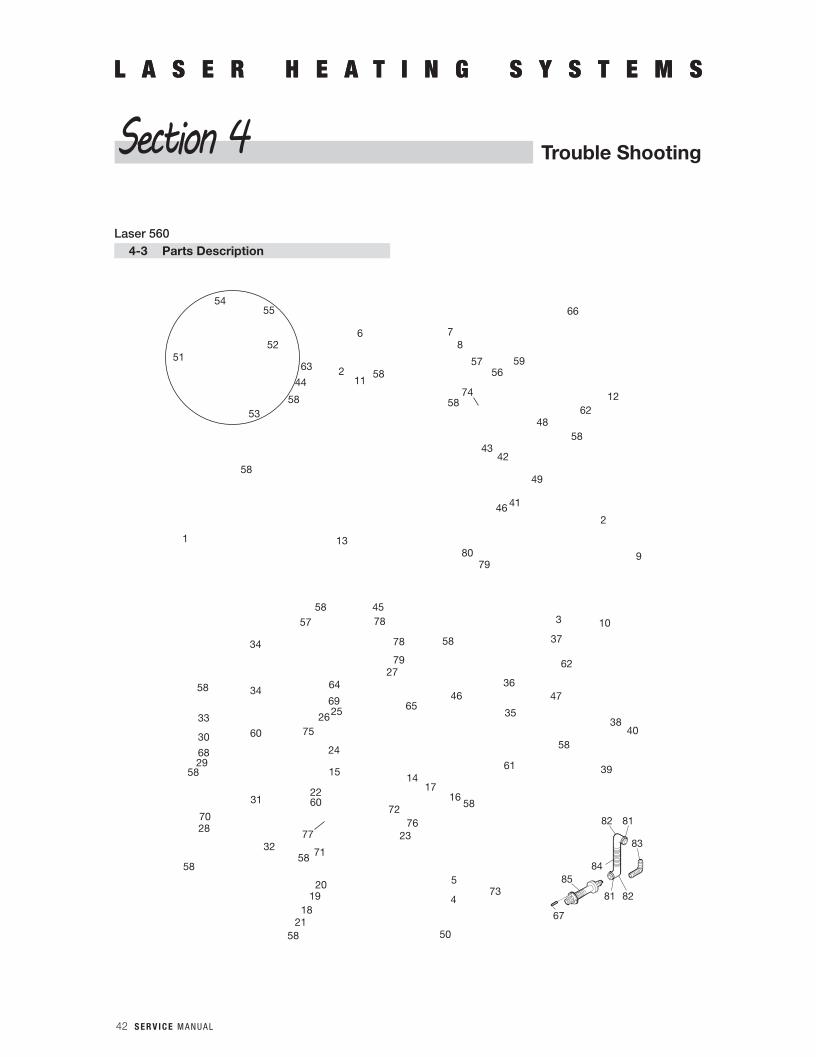
42 S E R V I C E M A N U A L
L A S E R H E A T I N G S Y S T E M SL A S E R H E A T I N G S Y S T E M S
Trouble ShootingSection 4
54
53
211
63
44
58
58
13
58
56
74
59
66
1262
5848
4342
49
4146
8079
46
79
78
2
9
345
27
65
64
692526
75
24
15
2260
77
1417
7672
1658
23
735
58 71
2019
1821
58
58
32
28
31
58
70
2968
30 60
3458
33
4
50
36
37
62
47
35
61
58
38
39
40
58
78 10
57
87
1
34
5758
58
6
51
84
67
85
82 81
83
81 82
55
52
Laser 5604-3 Parts Description
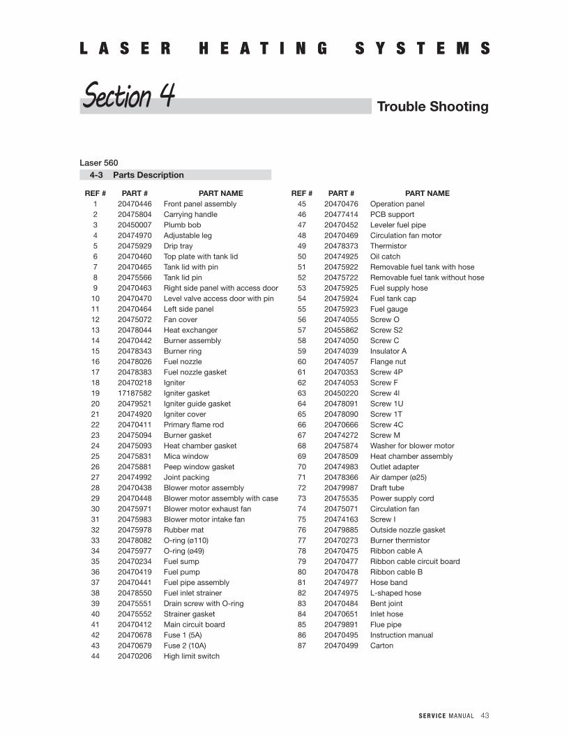
S E R V I C E M A N U A L 43
L A S E R H E A T I N G S Y S T E M S
Trouble Shooting
L A S E R H E A T I N G S Y S T E M S
Section 4
Laser 5604-3 Parts Description
REF # PART # PART NAME REF # PART # PART NAME1 20470446 Front panel assembly 45 20470476 Operation panel2 20475804 Carrying handle 46 20477414 PCB support3 20450007 Plumb bob 47 20470452 Leveler fuel pipe4 20474970 Adjustable leg 48 20470469 Circulation fan motor5 20475929 Drip tray 49 20478373 Thermistor6 20470460 Top plate with tank lid 50 20474925 Oil catch7 20470465 Tank lid with pin 51 20475922 Removable fuel tank with hose8 20475566 Tank lid pin 52 20475722 Removable fuel tank without hose9 20470463 Right side panel with access door 53 20475925 Fuel supply hose10 20470470 Level valve access door with pin 54 20475924 Fuel tank cap11 20470464 Left side panel 55 20475923 Fuel gauge12 20475072 Fan cover 56 20474055 Screw O13 20478044 Heat exchanger 57 20455862 Screw S214 20470442 Burner assembly 58 20474050 Screw C15 20478343 Burner ring 59 20474039 Insulator A16 20478026 Fuel nozzle 60 20474057 Flange nut17 20478383 Fuel nozzle gasket 61 20470353 Screw 4P18 20470218 Igniter 62 20474053 Screw F19 17187582 Igniter gasket 63 20450220 Screw 4l20 20479521 Igniter guide gasket 64 20478091 Screw 1U21 20474920 Igniter cover 65 20478090 Screw 1T22 20470411 Primary flame rod 66 20470666 Screw 4C23 20475094 Burner gasket 67 20474272 Screw M24 20475093 Heat chamber gasket 68 20475874 Washer for blower motor25 20475831 Mica window 69 20478509 Heat chamber assembly26 20475881 Peep window gasket 70 20474983 Outlet adapter27 20474992 Joint packing 71 20478366 Air damper (ø25)28 20470438 Blower motor assembly 72 20479987 Draft tube29 20470448 Blower motor assembly with case 73 20475535 Power supply cord30 20475971 Blower motor exhaust fan 74 20475071 Circulation fan31 20475983 Blower motor intake fan 75 20474163 Screw I32 20475978 Rubber mat 76 20479885 Outside nozzle gasket33 20478082 O-ring (ø110) 77 20470273 Burner thermistor34 20475977 O-ring (ø49) 78 20470475 Ribbon cable A35 20470234 Fuel sump 79 20470477 Ribbon cable circuit board36 20470419 Fuel pump 80 20470478 Ribbon cable B37 20470441 Fuel pipe assembly 81 20474977 Hose band38 20478550 Fuel inlet strainer 82 20474975 L-shaped hose39 20475551 Drain screw with O-ring 83 20470484 Bent joint40 20475552 Strainer gasket 84 20470651 Inlet hose41 20470412 Main circuit board 85 20479891 Flue pipe42 20470678 Fuse 1 (5A) 86 20470495 Instruction manual43 20470679 Fuse 2 (10A) 87 20470499 Carton44 20470206 High limit switch
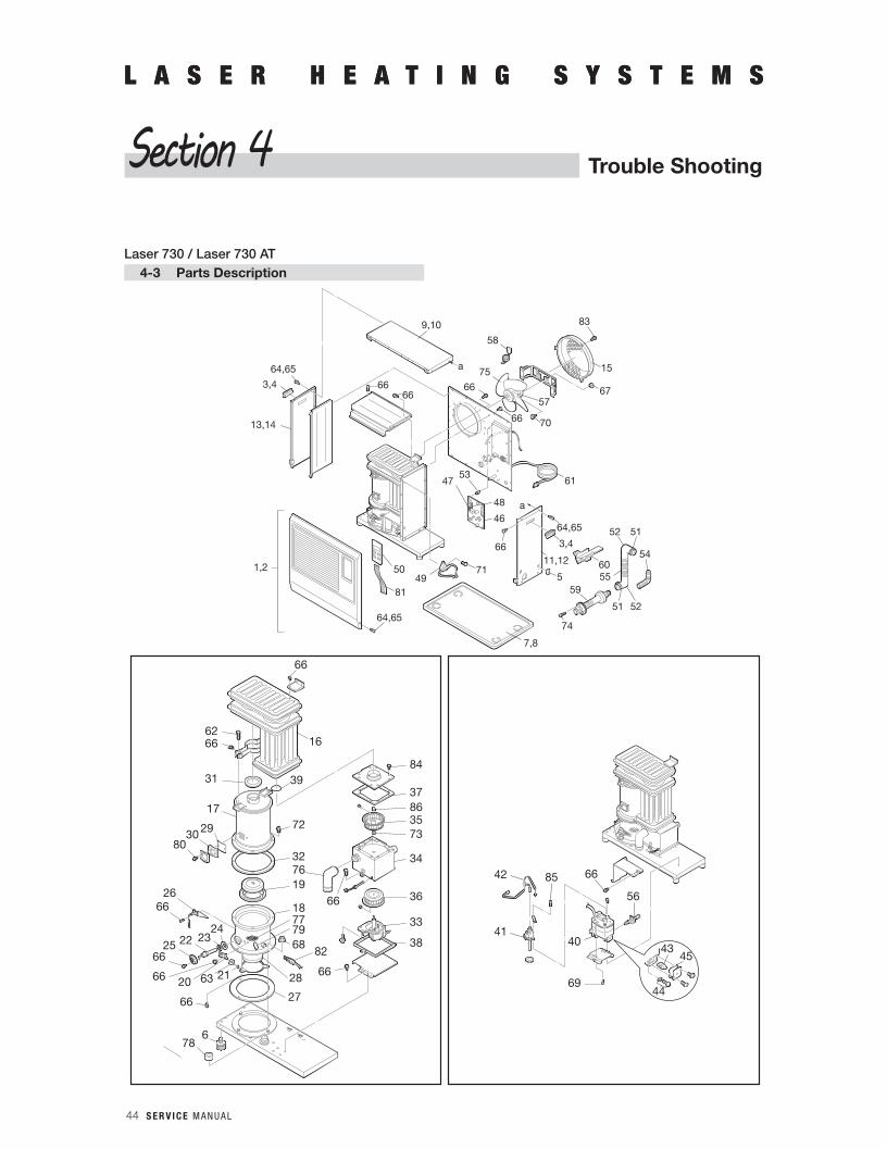
44 S E R V I C E M A N U A L
L A S E R H E A T I N G S Y S T E M SL A S E R H E A T I N G S Y S T E M S
Trouble ShootingSection 4
Laser 730 / Laser 730 AT4-3 Parts Description
3,4
13,14
6666
9,10
a64,65
58
67
15
83
75
66
66 70
57
61
64,65
3,4
11,12
571 60
4950
81
55
53
a
74
59
7,8
64,65
1,2
6685
56
69
4140
42
36
34
73358637
84
76
6619
16
39
72
32
6266
31
17
293080
66
66
38
3318
68
28
27
7779
26
2423
66
678
222566
66
2120 6366
82
66
45
44
43
48
46
47
52 51
54
51 52
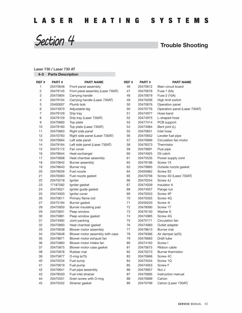
S E R V I C E M A N U A L 45
L A S E R H E A T I N G S Y S T E M SL A S E R H E A T I N G S Y S T E M S
Trouble ShootingSection 4
Laser 730 / Laser 730 AT4-3 Parts Description
REF # PART # PART NAME REF # PART # PART NAME1 20470646 Front panel assembly 46 20470612 Main circuit board2 20479145 Front panel assembly (Laser 730AT) 47 20470678 Fuse 1 (5A)3 20475804 Carrying handle 48 20470679 Fuse 2 (10A)4 20479104 Carrying handle (Laser 730AT) 49 20470206 High limit switch5 20450007 Plumb bob 50 20470676 Operation panel6 20474970 Adjustable leg 50 20470776 Operation panel (Laser 730AT)7 20478129 Drip tray 51 20474977 Hose band8 20479129 Drip tray (Laser 730AT) 52 20474975 L-shaped hose9 20470660 Top plate 53 20477414 PCB support10 20479160 Top plate (Laser 730AT) 54 20474984 Bent joint (L)11 20470663 Right side panel 55 20470651 Inlet hose12 20470763 Right side panel (Laser 730AT) 56 20470652 Leveler fuel pipe13 20470664 Left side panel 57 20470669 Circulation fan motor14 20479164 Left side panel (Laser 730AT) 58 20478373 Thermistor15 20475172 Fan cover 59 20479891 Flue pipe16 20478644 Heat exchanger 60 20474925 Oil catch17 20475808 Heat chamber assembly 61 20475535 Power supply cord18 20470642 Burner assembly 62 20478188 Screw 1X19 20478643 Burner ring 63 20479885 Outside nozzle gasket20 20478026 Fuel nozzle 64 20455862 Screw S221 20478383 Fuel nozzle gasket 65 20470756 Screw 4D (Laser 730AT)22 20470218 Igniter 66 20470254 Screw 4J23 17187582 Igniter gasket 67 20474039 Insulator A24 20479521 Igniter guide gasket 68 20474057 Flange nut25 20474920 Igniter cover 69 20470353 Screw 4P26 20470611 Primary flame rod 70 20470355 Screw 4Q27 20475194 Burner gasket 71 20450220 Screw 4I28 20475850 Burner insulating pad 72 20478090 Screw 1T29 20475831 Peep window 73 20476150 Washer E30 20475881 Peep window gasket 74 20474985 Screw 4G31 20474992 Joint packing 75 20475171 Circulation fan32 20475893 Heat chamber gasket 76 20474983 Outlet adapter33 20470638 Blower motor assembly 77 20478613 Burner mat34 20470648 Blower motor assembly with case 78 20478366 Air damper (ø25)35 20478871 Blower motor exhaust fan 79 20478683 Draft tube36 20475883 Blower motor intake fan 80 20474163 Screw I37 20475875 Blower motor case gasket 81 20470675 Ribbon cable38 20475878 Rubber mat 82 20470273 Burner thermistor39 20475877 O-ring (ø75) 83 20470666 Screw 4C40 20470234 Fuel sump 84 20475554 Screw 1Q41 20470619 Fuel pump 85 20474053 Screw F42 20470641 Fuel pipe assembly 86 20479957 Nut J43 20478550 Fuel inlet strainer 87 20470695 Instruction manual44 20475551 Drain screw with O-ring 88 20470699 Carton45 20475552 Strainer gasket 89 20470799 Carton (Laser 730AT)

TOYOTOMI U.S.A., INC.604 Federal Road, Brookfield, CT 06804
www.toyotomiusa.com
Printed in Japan
New 11/15
Part #B1500021