effect of change of contact ratio on contact fatigue
TRANSCRIPT

International Journal of Current Engineering and Technology E-ISSN 2277 – 4106, P-ISSN 2347 – 5161 ©2018 INPRESSCO®, All Rights Reserved Available at http://inpressco.com/category/ijcet
Research Article
719| International Journal of Current Engineering and Technology, Vol.8, No.3 (May/June 2018)
Effect of change of contact ratio on contact fatigue stress of involute spur gears Michael Gebremariam, Ashish Thakur*, Equbamariam Leake and Daniel Tilahun School of Mechanical and Industrial Engineering, Mekelle University, Mekelle. Ethiopia Solid Mechanics and Design Chair, Ethiopian Institute of Technology. Ethiopia Received 14 April 2018, Accepted 15 June 2018, Available online 20 June 2018, Vol.8, No.3 (May/June 2018)
Abstract This paper dealt on the effect of change of contact ratio on the contact fatigue stresses generated on meshing involute spur gear teeth during operation. In this study, different cases of six contact ratio gearing between and have been analyzed. For each contact ratio the rate of load sharing and angular and radial position of load were determined on the involute profile of meshing tooth of each gearing to determine contact fatigue stress at critical condition. To come up at the result CATIA and Solid Works software involute spur gear models have been developed for stress analysis on ANSYS Workbench (FEM). Because of the decrease in value and the change in location and direction of applied load, higher contact ratio gearing resulted higher generated tooth fatigue contact stress life. The results obtained from ANSYS Workbench are compared with results of the AGMA gear formula results. Keywords: Gear teeth, ANSYS, contact ratio, contact fatigue, AGMA 1. Introduction
1 Gearing is the special division of Mechanical Engineering concerned with the transmission of power and motion between the rotating shafts. Gears not only transmit motion and enormous power satisfactorily, but can do so with very uniform motion. It is the best and the economical means of achieving this transmission. Gear teeth fails due to the static and the dynamic loads acting over it, also the contact between the two meting gears causes the surface failures. The gear fails without any warning and the results due to this failure are catastrophic. Gear are used to transmit torque , motion and angular velocity from one shaft to another in a wide variety of applications there is also a wide variety of gear types to choose from. The motion from one shaft to another shaft may be transmitted with belts, ropes and chains are when the two shafts are having long center distance. But, if the distance between the two shafts is very small, then gears are used to transmit motion from one shaft to another [B.Venkateshet al, 2010]. Although gears have gained wide range of acceptance in all kinds of applications they have to resist the bending and fatigue stresses produced due to the cyclic load during power transmission. However;
*Corresponding author’s Email: ORCID ID: 0000-0001-9287-700X DOI: https://doi.org/10.14741/ijcet/v.8.3.27
after the investigation of shot peening to increase the tooth bending strength in gears, surface durability, in the form of macro and micro-pitting, is now considered the dominant restriction on gear life and performance [Rubén D. Chacónet al, 2005]. In addition to that, failure of tooth due to bending (breakage) tends to be catastrophic to a gear unit, so the designer usually makes the teeth large enough so that they are definitely less appropriate to fail in breakage mode than in a pitting mode. This makes the design life of a gear unit primarily dependent on its surface fatigue capacity (pitting resistance) rather than on its cantilever beam capacity (capacity to resist tooth breakage) [Robert. L. Norton et al, 2006]. A majority of the heavily loaded transmissions used in military applications use gears with a contact ratio less than 2.0. The contact ratios of these transmissions are in the range of 1.3 to 1.8. So, the number of teeth in engagement at any instant is either one or two [J. Shigleyet al, 2006]. Hence, increasing the load carrying capacity of gears for the above conditions can be done by the design of gears with a contact ratio greater than or equal to 2.0. High contact ratio gears having a contact ratio greater than 2.0 have load sharing between two or three teeth during engagement and fewer loads per tooth [Andrew Sommeret al, 1998].
2. Literature Review Gears are used in many fields and under a wide range of conditions such as in smaller watches and

Michael Gebremariam, Ashish Thakur, Equbamariam Leake and Daniel Tilahun Effect of change of contact ratio on contact..
720| International Journal of Current Engineering and Technology, Vol.8, No.3 (May/June 2018)
instruments to the heaviest and most powerful machineries like lifting cranes. Gears are most commonly used for power transmission in all the modern devices. These toothed wheels are used to change the speed or power between two stages (input and output) [B.Venkateshet al, 2010]. [B.Venkateshet al, 2010], has studied on helical gear which offers high contact and more friction and avoids slippage when compared to spur gear. To estimate the bending stress, three dimensional solid models for different number of teeth are generated by CATIA that is powerful and modern modeling software and the numerical solution is done by ANSYS, which is a finite element analysis package. His analytical investigation is based on Lewis stress formula. The aim of the study is to focus on reduction of weight and thereby reducing the unbalance forces setup in the system. [Ali R.H et al, 2009], Investigated natural frequencies and dynamic response of a spur gear sector using a two dimensional finite element model that offers significant advantages for dynamic gear analyses. The gear teeth are analyzed for different operating speeds. A primary feature of this modeling is determination of mesh forces using a detailed contact analysis for each time step as the gears roll through the mesh. ANSYS software has been used on the proposed model to find the natural frequencies and displacements and dynamic stresses by transient mode super position method. [Andrew Sommeret al, 1998], Demonstrated the early transient dynamic loading on teeth within a fixed-axis gear transmission arising from backlash and geometric manufacturing errors by utilizing a non-linear multi-body dynamics software model. Selection of the non-linear contact parameters such as the stiffness, force exponent, damping, and friction coefficients are presented for a practical transmission. Backlash between gear teeth which is essential to provide better lubrication on tooth surfaces and to eliminate interference is included as a defect and a necessary part of transmission design. [M. Rameshkumaret al, 2010], Studied in high precision and heavily loaded spur gears. In this study the effect of gear errors is negligible, so the periodic variation of tooth stiffness is the principal cause of noise and vibration. [EvgenyPodzharovet al, 2008], Says the gears used in vehicles should have lesser noise and vibration. Even though helical gears will meet the requirement, they are prone for additional axial thrust problem. In his study high contact ratio (HCR) is one such gearing concept used for achieving high load carrying capacity with less volume and weight. Contact ratio greater than 2.0 in HCR gearing results in lower bending and contact stresses. [P.J.L. Fernandeset al, 1997], referred that surface contact fatigue is the most common cause of gear failure. It results in damage to contacting surfaces which can significantly reduce the load-carrying of components, and may ultimately lead to complete failure of a gear.
[Rubén D. Chacónet al, 2005], in this paper a study of the stresses in the contact zone among a couple of spur gears is realized using the finite elements method. The analysis is done by using a plane model involving the contact between two teeth. The geometry is defined according to the standards of the American Gear Manufacturers Association (AGMA). 2.1. Spur Gear Tooth Theory 2.1.1 Surface Failure When two bodies having curved surfaces are pressed together, point or line contact changes to area contact, and the stresses developed in the two bodies are three-dimensional. [Evgeny Podzharovet al, 2008], when the two surfaces are in pure rolling contact, or are primarily rolling in combination with a small percentage of sliding, a different surface failure mechanism comes into play, called surface fatigue. Many applications of this condition exist in such as ball and roller bearings, cams with roller followers, nip rolls, and spur or helical gear tooth contact. All except the gear teeth and nip rolls typically have essentially pure rolling with only about I% sliding. Gear teeth have significant sliding at portions of their tooth interface and this will change the stress state significantly compared to the pure rolling cases. Typical failures are seen as cracks, pits, or flaking in the surface material. Under contact conditions, gear teeth are subjected to Hertzian contact stresses and elasto-hydrodynamic lubrication. Excessive loading and lubrication breakdown can cause combinations of abrasion, pitting and scoring. We can define the surface failures as follows: Pitting or surface fatigue failure: Pitting is phenomenon in which small particles are removed from the surface of the tooth because of the high contact forces that are present between mating teeth. It is actually the fatigue failure of the tooth surface [Colbourne J.R et al, 1987]. Complex stresses within the contact zone cause surface and subsurface fatigue failures. An example of pitch line contact fatigue is shown in Fig. 1 [8]. The pits seen on the teeth grow in size and depth, ultimately resulting in tooth fracture and spalling [T.E. Tallianet al, 1992]. [Andrew Sommeret al, 1998] Pitting occurs only after a large number of repeated loading on the contact surfaces of the teeth. It is found to occur most frequently at the pitch circle - where relative sliding of the teeth is zero and the hydrodynamic lubricant film tends to break down.
2.1.2. Spur Gear Tooth Contact Fatigue Analysis
Pitting is a fatigue failure where small cracks form in the tooth surface and then grow to the point where small, round bits of metal break out of the tooth surface. Traditionally, the gear designer first determines a pitch diameter and a face width for the pinion that are large enough for the pinion to last for

Michael Gebremariam, Ashish Thakur, Equbamariam Leake and Daniel Tilahun Effect of change of contact ratio on contact..
721| International Journal of Current Engineering and Technology, Vol.8, No.3 (May/June 2018)
the required service life with a probability of failure less than 1%. This determination is based on a possible pitting fatigue failure. It is assumed in the beginning that the surface finish, the tooth accuracy, the lubrication, and the needed profile and helix modifications will all be carried out well enough to avoid any serious risk of scuffing. Normally, the pinion is more appropriate to fail in pitting than the gear, so the sizing of the pinion tends to determine the needed size of the gear. After the pitch diameter of the pinion has been determined, the size of the teeth is determined by calculations regarding a possible failure in tooth breakage. Standard , suggests allowable contact-stress numbers (for cycles and reliability for through hardened steel gears) as high as ( ) for grade 2. AGMA Standard 2101-D04 strength equation, for allowable contact stress, is given by
Where, is Permissible contact stress taking into
account fatigue strength, [MPa] is Fatigue limit taking into account contact
stress, [MPa] is stress cycle factor for pitting resistance is the hardness ratio factors for pitting
resistance is the temperature factor is the reliability factor is the factor of safety, a stress ratio AGMA Standard 2101-D04 provides the following improved rating formula and permissible stresses applicable for calculating the pitting resistance of external cylindrical involute gear teeth operating on parallel axes [B.Venkateshet al, 2010].
√
(1)
Where: : Pitting resistance (Contact stress), [MPa]
: Elastic coefficient, [√ ]
: Transmitted tangential load, [N] : Overload factor : Dynamic factor : Load distribution factor : Size factor : Surface condition factor for pitting resistance : Face width, [mm] : Operating diameter of pinion, [mm] : Geometry factor for pitting resistance
Pitting Resistance Stress Cycle Factor Analysis
By means of mathematical processing of formula above it is possible to determine the stress cycle factor for pitting resistance according to equation below
√
(2)
2.1.3. Expected Fatigue Lifetime Analysis The number of load cycles expected by pitting ( ) can be evaluated with the stress cycle factor determined by the formulas above and graphical information presented on [AGMA 2101-D04, 2001]. Once certain that the numbers of load cycles corresponding to calculated values of factor the hours of expected fatigue lifetime ( ) can be known by means of the following equation.
(3)
But (
)
(
)
Where: : Number of load cycles expected by pitting in corresponding with stress cycle factor : Rotational speed, (min-1) : Number of load application by 1 turn of gear Contact Ratio Contact ratio is defined as a number of teeth in contact at one time as these teeth pass through the contact zone. In other words, contact ratio is a number which indicates the average number of pairs in contact [R.S. Khurmiet al, 2005]. Length of line of action, AB is:
√( ) ( )
√( ) ( )
( ) (4) By substituting in ⁄ , Contact ratio can be written as:
[√( )
( ) √( )
( ) (
) ] (5) But , equation above will become:
√( )
( )
( )
√( ) ( ) ( ) ( )
( ) (6)
Where, and : are the operating pitch radius of the pinion and gear respectively, : is the operating pressure angle; : is the module and is the addendum (based on the operating pitch radius) which is equal to one module for standard gears. Most spur gear sets will have contact ratios between 1.4 and 2 [Sabah M.J.Aliet al, 2007]. For normal contact ratio gearing the number of meshing teeth alternates between one and two.
Michael Gebremariam, Ashish Thakur, Equbamariam Leake and Daniel Tilahun Effect of change of contact ratio on contact..
722| International Journal of Current Engineering and Technology, Vol.8, No.3 (May/June 2018)
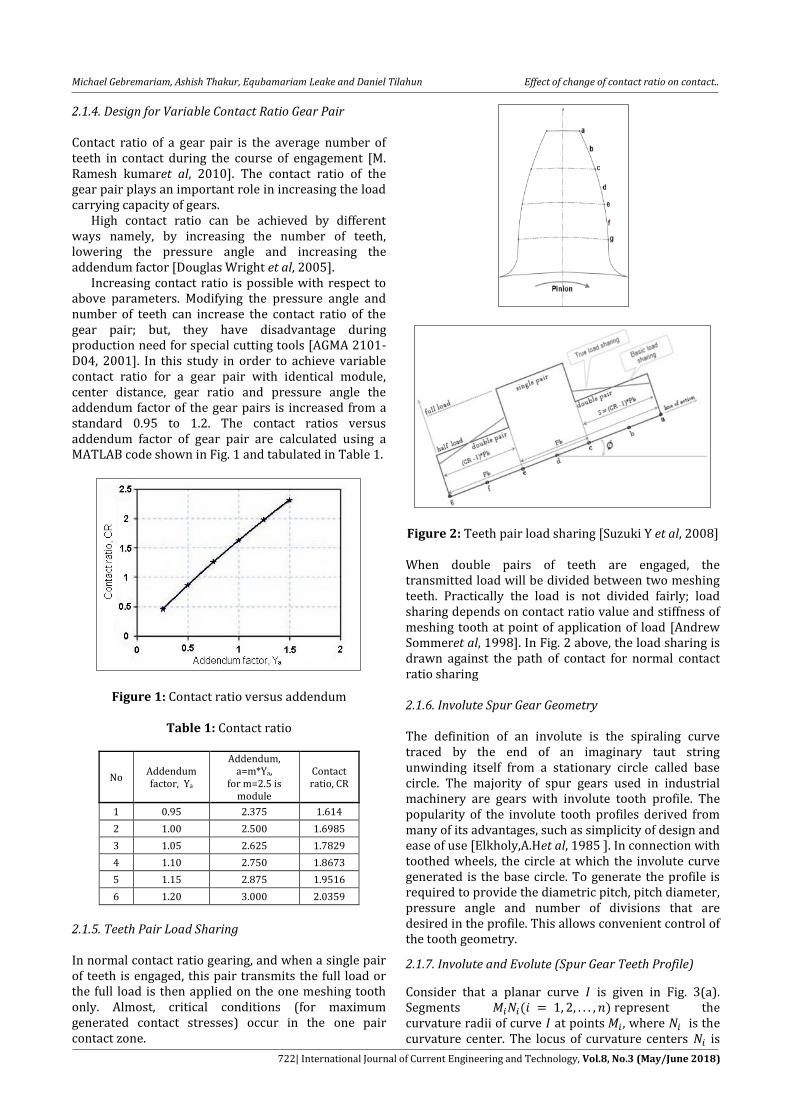
2.1.4. Design for Variable Contact Ratio Gear Pair Contact ratio of a gear pair is the average number of teeth in contact during the course of engagement [M. Ramesh kumaret al, 2010]. The contact ratio of the gear pair plays an important role in increasing the load carrying capacity of gears. High contact ratio can be achieved by different ways namely, by increasing the number of teeth, lowering the pressure angle and increasing the addendum factor [Douglas Wright et al, 2005]. Increasing contact ratio is possible with respect to above parameters. Modifying the pressure angle and number of teeth can increase the contact ratio of the gear pair; but, they have disadvantage during production need for special cutting tools [AGMA 2101-D04, 2001]. In this study in order to achieve variable contact ratio for a gear pair with identical module, center distance, gear ratio and pressure angle the addendum factor of the gear pairs is increased from a standard 0.95 to 1.2. The contact ratios versus addendum factor of gear pair are calculated using a MATLAB code shown in Fig. 1 and tabulated in Table 1.
Figure 1: Contact ratio versus addendum
Table 1: Contact ratio
No Addendum factor, Ya
Addendum, a=m*Ya,
for m=2.5 is module
Contact ratio, CR
1 0.95 2.375 1.614
2 1.00 2.500 1.6985
3 1.05 2.625 1.7829
4 1.10 2.750 1.8673
5 1.15 2.875 1.9516
6 1.20 3.000 2.0359
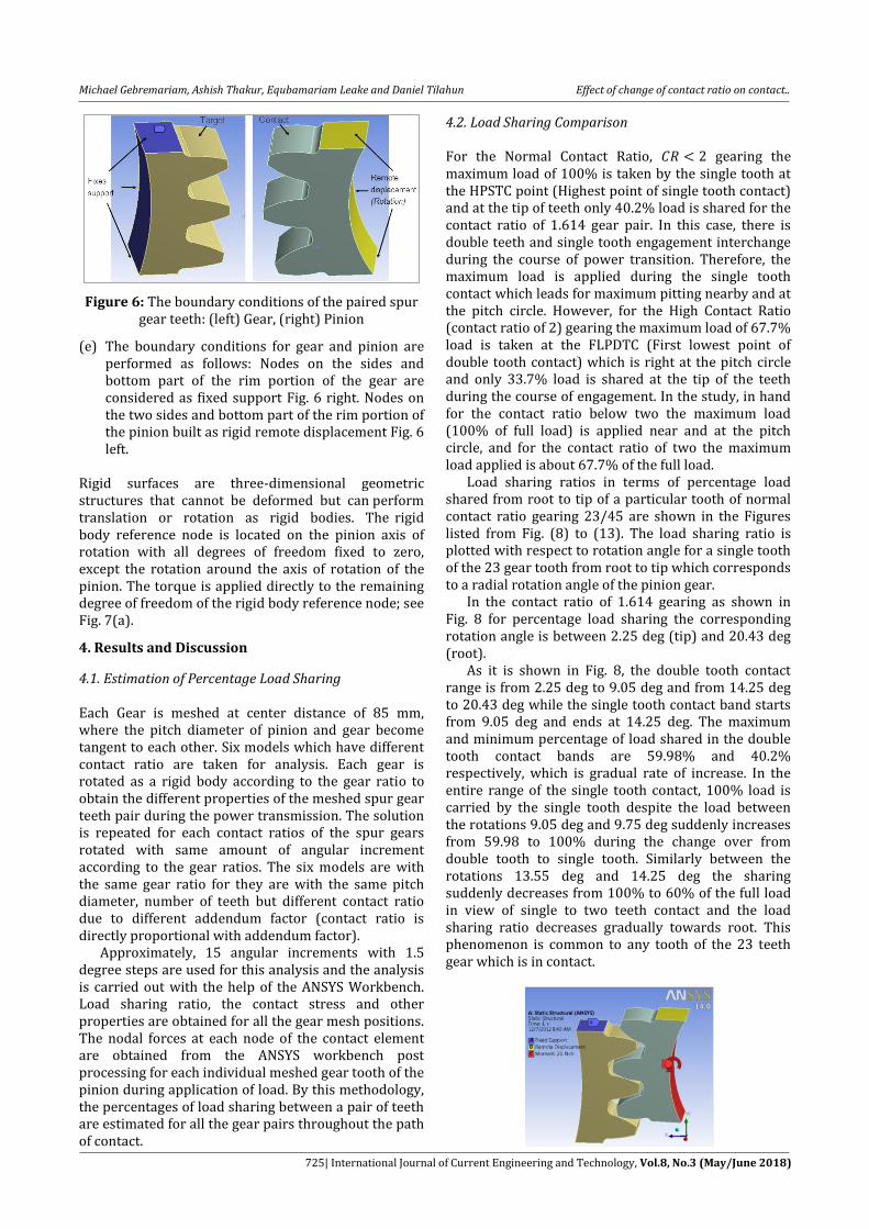
2.1.5. Teeth Pair Load Sharing In normal contact ratio gearing, and when a single pair of teeth is engaged, this pair transmits the full load or the full load is then applied on the one meshing tooth only. Almost, critical conditions (for maximum generated contact stresses) occur in the one pair contact zone.
Figure 2: Teeth pair load sharing [Suzuki Y et al, 2008] When double pairs of teeth are engaged, the transmitted load will be divided between two meshing teeth. Practically the load is not divided fairly; load sharing depends on contact ratio value and stiffness of meshing tooth at point of application of load [Andrew Sommeret al, 1998]. In Fig. 2 above, the load sharing is drawn against the path of contact for normal contact ratio sharing 2.1.6. Involute Spur Gear Geometry The definition of an involute is the spiraling curve traced by the end of an imaginary taut string unwinding itself from a stationary circle called base circle. The majority of spur gears used in industrial machinery are gears with involute tooth profile. The popularity of the involute tooth profiles derived from many of its advantages, such as simplicity of design and ease of use [Elkholy,A.Het al, 1985 ]. In connection with toothed wheels, the circle at which the involute curve generated is the base circle. To generate the profile is required to provide the diametric pitch, pitch diameter, pressure angle and number of divisions that are desired in the profile. This allows convenient control of the tooth geometry.
2.1.7. Involute and Evolute (Spur Gear Teeth Profile)
Consider that a planar curve is given in Fig. 3(a). Segments ( ) represent the curvature radii of curve at points , where is the curvature center. The locus of curvature centers is

Michael Gebremariam, Ashish Thakur, Equbamariam Leake and Daniel Tilahun Effect of change of contact ratio on contact..
723| International Journal of Current Engineering and Technology, Vol.8, No.3 (May/June 2018)
the evolute to curve . The main features of , evolute to curve , are as follows: Considering as given, we may determine the involute for as the result of development of . Let us imagine an inextensible thread that is wrapped on curve . Point of the thread will trace out the involute while the thread is wound on and off.
Figure 3: Geometry of Involute curves: (a) involute and evolute, (b) for derivation of the equation of
involute curves [ISO 6336-1, 1996]. The analytical representation of an involute curve is based on the following equations. ( ) (7) ( ) (8)
3. Finite Element Analysis A new method, Finite Element Analysis (FEA) is used extensively nowadays for calculations of the strength and deflections of mechanical engineering components including gear teeth. Once these techniques were only used by big companies due to their complexity and price, but with the development of computer technology they have become more and more accessible to small gear companies, which are the majority of participants in the market [Durmuset al, 1996; Vanyo Kirovet al, 2011; G. Lundberget al, 1947]. [Faydor L. Litvinet al, 2004], Discussed that the finite element analysis allows us to perform; stress analysis, investigation of formation of gear contact,
detection of severe areas of contact stresses inside the cycle of meshing. The contact conditions are sensitive to the geometry of the contacting surfaces, which means that the finite element mesh near the contact zone needs to be highly refined. Finer meshing generally leads to a more accurate solution, but requires more time and system resources [P. Kumaret al, 2009]. It is recommended not to have a fine mesh everywhere in the model to reduce the computational requirements. To perform this application, developing of finite element mesh of the gear drive, defining the contact surfaces of the teeth pair and establishing the boundary conditions of the loading of the gear drive are carried out before the analysis is performed in ANSYS 14. This procedure is deployed to generate the finite element model as seen in Fig. 4 given below. After the 3D model generated in CATIA V5R16 and assembled in Solid Works 10 is imported to ANSYS 14.0.
Figure 4: Meshed spur gear teeth pair A free and mapped meshing capability of ANSYS Workbench is employed to generate the finite element mesh. Refinement in the contact region is performed using contact sizing option. Then, the meshing performed to generate the finite elements. The finite element mesh is generated in such a way that to decrease element size at the contact region (maximum stress region), increase the size of the elements when moving away from the contact region, so that there will be, more number of small size elements in the contact region and less number of elements in low stress regions respectively to reduce the computation time and computer memory requirement, within reasonable accuracy.
3.1. Generation of Spur Gear The spur gear pair with the properties given in Table 2 is chosen to model the problem at hand. Using these parameters and the involute curve equation the solid models created in CATIA V5R16. In order to generate involute profile in CATIA, five key points are created in the range of Dedendum and Addendum circle radii representing the involute profile using equation 7 and 8. These points represent radii values in the range of Dedendum and Addendum circle. All these radii values are connected with spline, in generative shape design

Michael Gebremariam, Ashish Thakur, Equbamariam Leake and Daniel Tilahun Effect of change of contact ratio on contact..
724| International Journal of Current Engineering and Technology, Vol.8, No.3 (May/June 2018)
modeler. Once the involute shape is generated, by using extrapolation, reflection, and array command the 3D model is developed. Developed solid meshing of the spur gear is shown in Fig. 5 given below. Then the 3D model is imported to Solid Works 10 for assembling, and after that it is imported to ANSYS workbench for the purpose of finite element analysis. However, to minimize computation time, only a three pairs of meshed teeth model is imported to ANSYS Workbench 14.0 to carry out the analysis.
Table 2: Spur Gear Parameters
Parameters pinion gear
Module, m [mm] 2.5 2.5 Pressure angle, [deg] 20 20
Number of teeth, z 23 45 Face width, b [mm] 10 10
Pitch circle diameter, D [mm]
57.5 112.5
Materiality
Chromium-molybdenum
alloy steel (SCM 420)
Chromium-molybdenum
alloy steel (SCM 420)
Modules of elastic [GPa] 206 206 Poisson’s ratio 0.3 0.3
Applied torque [Nm] 25 Center distance [mm] 85
Figure 5: Meshed Spur Gear
ANSYS Contact Models
ANSYS supports five contact models: node-to-node, node-to-surface, surface-to-surface, line-to-line, and line-to-surface [J. Shigleyet al, 2006]. Surface-to-surface contact is typically used to model surface-to-surface contact applications. The finite element model recognizes possible contact pairs by the presence of specific contact elements. These contact elements are overlaid on the parts of the model that are being analyzed for interaction. In this study, two faces of the contacted teeth pairs are taken to employee the surface-to-surface contact. In problems involving contact between two boundaries, one of the boundaries is conventionally established as the "target" surface, and the other as the "contact" surface. For rigid-flexible contact, the target surface is always the rigid surface, and the contact surface is the deformable surface. For flexible-to-flexible contact, both contact and target surfaces are associated with the deformable bodies. These two surfaces together comprise the "contact pair." For 3-D
contact pairs, TARGE170 with CONTA174 are used for the surfaces in contact. Each contact pair is identified via the same real constant number. To create a contact pair, the same real constant number to both the target and contact elements is assigned as per the software command permits. The Employed ANSYS Analysis Steps To come up the final result different steps are used, starting from modeling the spur gear in CATIA to stress analysis of the model in ANSYS workbench. Although the steps used are many, to make general summary they are classified into five as discussed below. [Solomon T et al, 2011], has utilized similar steps in his study. (a) The model is generated using the equations of
involute profile for spur gear tooth, (for both the
pinion and the gear), in CATIA V5R16. Then, after
assembling the model in Solid Works 10, three
pairs of gear teeth is imported in to ANSYS
Workbench 14.0 as working model.
(b) Modules for automatic generation of finite element
models are integrated into the model in ANSYS
Workbench version 14.0, static structural analysis
system. Then, the generation of finite element
models is accomplished for the cycle of meshing.
(c) Define material properties which are necessary to
solve the problem. Here, the gear material is
16MnCr5 and the required material properties for
this analysis are only Modulus of Elasticity,
Poison's Ratio and Density. The Modulus of
Elasticity of 16MnCr5 is 206 GPa, Poison’s Ratio of
16MnCr5 is 0.3 and the Density of 16MnCr5 is
7850 kg/m3.
(d) To get the contact stresses the contact wizard is
used in ANSYS Workbench. The contact algorithm
in ANSYS Workbench computer program requires
definition of contacting surface. To define a contact
pair completely, contact and target element are
referred to same characteristic parameters as
CONTA174 and target170. Then, augmented
Lagrangian method contact algorithm, with
frictionless contact is used.
Michael Gebremariam, Ashish Thakur, Equbamariam Leake and Daniel Tilahun Effect of change of contact ratio on contact..
725| International Journal of Current Engineering and Technology, Vol.8, No.3 (May/June 2018)
Figure 6: The boundary conditions of the paired spur gear teeth: (left) Gear, (right) Pinion
(e) The boundary conditions for gear and pinion are performed as follows: Nodes on the sides and bottom part of the rim portion of the gear are considered as fixed support Fig. 6 right. Nodes on the two sides and bottom part of the rim portion of the pinion built as rigid remote displacement Fig. 6 left.
Rigid surfaces are three-dimensional geometric structures that cannot be deformed but can perform translation or rotation as rigid bodies. The rigid body reference node is located on the pinion axis of rotation with all degrees of freedom fixed to zero, except the rotation around the axis of rotation of the pinion. The torque is applied directly to the remaining degree of freedom of the rigid body reference node; see Fig. 7(a).
4. Results and Discussion
4.1. Estimation of Percentage Load Sharing Each Gear is meshed at center distance of 85 mm, where the pitch diameter of pinion and gear become tangent to each other. Six models which have different contact ratio are taken for analysis. Each gear is rotated as a rigid body according to the gear ratio to obtain the different properties of the meshed spur gear teeth pair during the power transmission. The solution is repeated for each contact ratios of the spur gears rotated with same amount of angular increment according to the gear ratios. The six models are with the same gear ratio for they are with the same pitch diameter, number of teeth but different contact ratio due to different addendum factor (contact ratio is directly proportional with addendum factor). Approximately, 15 angular increments with 1.5 degree steps are used for this analysis and the analysis is carried out with the help of the ANSYS Workbench. Load sharing ratio, the contact stress and other properties are obtained for all the gear mesh positions. The nodal forces at each node of the contact element are obtained from the ANSYS workbench post processing for each individual meshed gear tooth of the pinion during application of load. By this methodology, the percentages of load sharing between a pair of teeth are estimated for all the gear pairs throughout the path of contact.
4.2. Load Sharing Comparison For the Normal Contact Ratio, gearing the maximum load of 100% is taken by the single tooth at the HPSTC point (Highest point of single tooth contact) and at the tip of teeth only 40.2% load is shared for the contact ratio of 1.614 gear pair. In this case, there is double teeth and single tooth engagement interchange during the course of power transition. Therefore, the maximum load is applied during the single tooth contact which leads for maximum pitting nearby and at the pitch circle. However, for the High Contact Ratio (contact ratio of 2) gearing the maximum load of 67.7% load is taken at the FLPDTC (First lowest point of double tooth contact) which is right at the pitch circle and only 33.7% load is shared at the tip of the teeth during the course of engagement. In the study, in hand for the contact ratio below two the maximum load (100% of full load) is applied near and at the pitch circle, and for the contact ratio of two the maximum load applied is about 67.7% of the full load. Load sharing ratios in terms of percentage load shared from root to tip of a particular tooth of normal contact ratio gearing 23/45 are shown in the Figures listed from Fig. (8) to (13). The load sharing ratio is plotted with respect to rotation angle for a single tooth of the 23 gear tooth from root to tip which corresponds to a radial rotation angle of the pinion gear. In the contact ratio of 1.614 gearing as shown in Fig. 8 for percentage load sharing the corresponding rotation angle is between 2.25 deg (tip) and 20.43 deg (root). As it is shown in Fig. 8, the double tooth contact range is from 2.25 deg to 9.05 deg and from 14.25 deg to 20.43 deg while the single tooth contact band starts from 9.05 deg and ends at 14.25 deg. The maximum and minimum percentage of load shared in the double tooth contact bands are 59.98% and 40.2% respectively, which is gradual rate of increase. In the entire range of the single tooth contact, 100% load is carried by the single tooth despite the load between the rotations 9.05 deg and 9.75 deg suddenly increases from 59.98 to 100% during the change over from double tooth to single tooth. Similarly between the rotations 13.55 deg and 14.25 deg the sharing suddenly decreases from 100% to 60% of the full load in view of single to two teeth contact and the load sharing ratio decreases gradually towards root. This phenomenon is common to any tooth of the 23 teeth gear which is in contact.

Michael Gebremariam, Ashish Thakur, Equbamariam Leake and Daniel Tilahun Effect of change of contact ratio on contact..
726| International Journal of Current Engineering and Technology, Vol.8, No.3 (May/June 2018)
Figure 7: Applied Torque and Reaction force: (a) Torque applied on pinion, (b) Reaction force applied on
pinion tooth from gear tooth
Figure 8: Load sharing of 23/45 teeth of contact ratio 1.614
In the case of 1.6985 contact ratio gearing the corresponding rotation angle for load sharing is between 1.76 deg (tip) and 20.92 deg (root).
Figure 9: Load sharing of 23/45 teeth of contact ratio 1.6985
In the case of 1.7829 contact ratio gearing the corresponding rotation angle for load sharing is between 1.27 deg (tip) and 21.42 deg (root).
Figure 10: Load sharing of 23/45 teeth of contact ratio 1.7829
When the 1.8673 contact ratio gearing is considered the corresponding rotation angle for load sharing becomes between 0.77 deg (tip) and 21.91 deg (root).
Figure 11: Load sharing of 23/45 teeth of contact ratio 1.8673
When the 1.9561 contact ratio gearing is considered the corresponding rotation angle for load sharing becomes between 0.28 deg (tip) and 22.40 deg (root).
Figure 12:Load sharing of 23/45 teeth of contact ratio 1.9561
When the 2.00 contact ratio gearing is considered the corresponding rotation angle for load sharing becomes between 0.0 deg (tip) and 22.68 deg (root). It can be seen from the Fig. 13 that the double tooth contact band is throughout the entire engagement, which is from 0.00 deg to 22.68 deg. The maximum and minimum percentage loads shared in the entire double tooth contact range are 67.66% and 33.74% respectively. Maximum Critical load is 67.66 % of the transmitted load when C.R is 2.0.
Figure 13: Load sharing of 23/45 teeth of contact ratio 2.00

Michael Gebremariam, Ashish Thakur, Equbamariam Leake and Daniel Tilahun Effect of change of contact ratio on contact..
727| International Journal of Current Engineering and Technology, Vol.8, No.3 (May/June 2018)
4.3. Comparison of Von Mises Stress The maximum load which causes the higher stress on the tooth in mesh of the different gearing is on the regions, at which the single tooth carries 100% of the full load during power transmission. Von Mises stress distribution for Single pair teeth contact and Double pair teeth contact are shown in Fig. 14(a) and (b) given below.
Figure 14: Von Mises stress distribution: (a) Single pair teeth contact, (b) Double pair teeth contact
In this study, the Von Mises stress at the meshes was calculated based on the tooth load distributed on a unit contact area of the tooth surface. A reduction in the load sharing happens due to the increase of the addendum factor and the number of double teeth contact region, resulting in a lesser Von Mises stress. The variation of Von Mises stress on the 23 tooth normal contact ratio gear as shown in Figures 15 (a-f) resemble the load sharing behavior. For instance, if we take the 1.614 contact ratio gearing Fig. (15a), the stress varies from 227.59 MPa at the tip to 288.94 MPa at the start of single tooth contact, corresponding to 9.05 degrees, then after sudden increase to 374.75 MPa at the 9.75 degree rotation, the stress maintains to increase to 382.79 MPa till the rotation comes to 13.55 degree, then the stress goes to sudden decrease at the end of single pair teeth contact to 297.23 MPa at 14.25 degrees rotation and gradually decreases to 246.72 MPa at the root part of the teeth, in a manner similar to the load sharing pattern. When the contact ratio comes to 2.00 gearing Fig. 15(f) the maximum stress on the teeth is 311.80 MPa corresponding to 11.65 deg which is at the pitch circle. At the tip and root part of teeth the stress goes
decreasing to 207.58 MPa and 229.79 MPa respectively. In general, the load carrying capacity of the teeth increases with increasing the contact ratio of the gear. As a result the Von Mises stress is lower for the higher contact ratio gearing. However, when the contact ratio is changed from 1.9 to 2.0, the decrease of stresses was more than the decrease of stresses when the contact ratio is changed between any two other successive cases.

Michael Gebremariam, Ashish Thakur, Equbamariam Leake and Daniel Tilahun Effect of change of contact ratio on contact..
728| International Journal of Current Engineering and Technology, Vol.8, No.3 (May/June 2018)
Figure 15:Von Mises stress of 23/45 teeth of different contact ratio gearing: (a) CR=1.614, (b) CR=1.6985, (c) CR=1.7829, (d) CR=1.8673, (e) CR=1.9561, (f) CR=2.00 4.4. Critical Point Contact Stress When the contact ratio changes, the path of contact and
the load sharing will be changed too. As explained
earlier the load sharing which leads to critical loading
is with in the higher load sharing region. To explain
how to determine the location of the critical stress and
the angular position of the meshing tooth for each case
of contact ratio, see Fig. 2.
For comparison the contact stress variation at the
two ranges at which single tooth loading begines and
ends (line “c” and “e” respectively) for the different
contact ratio gearing is shown in Fig. 17. The contact
stress at line “c” for the least contact ratio gearing (CR=
1.614) is 666.904 MPa and at line “e” is 686.189 MPa,
in addition if we observe for the rest contact ratio
gearing the maximum stress is at line “e”, untill the CR
becomes greater and equal to 1.9561. It is clear that the
meshing at line “e” with full applied load on meshing
tooth, leads to a maximum generated stresses in
contact area, hence the load applied on point “e” is
the critical load. Meshing at point “e” creates the
largest possible contact stress with single pair of teeth
contact; so that point “e” is called the highest point of
single tooth contact.
The space between the two points (“c” and “e”)
becomes smaller as the contact ratio of the gears goes
larger until contact ratio of 1.95, refer Fig. 2 given
above. Beyond contact ratio 1.95 gearing the two
points are merged with point “d” (pitch circle). This
means single pair of teeth mesh is eliminated and
every contact will be between two pairs of teeth as
result the load will be shared between them.
Figure 16: Contact pressure distribution
Figure 17: Contact stress versus Contact Ratio at line “e” and “c”
4.4.1. Comparison of Theoretical (AGMA) and ANSYS (FEA) results The theoretical (AGMA) and ANSYS Contact stress (pitting resistance) results difference for the different contact ratio gearing is shown in Fig. 17. Results obtained of contact stress compared by AGMA and ANSYS are presented in Table 3 which shows that contact stress of AGMA is little bit higher than ANSYS. Even though, FEA is superior to AGMA and can be used extensively to solve different mechanical problem, it is necessary to remember that FEA has its inherent errors, and the AGMA calculations are based on empirical and proven by field experiments [EvgenyPodzharovet al, 2008]. The results calculated from AGMA (equation) and solved in ANSYS Workbench at the critical line of contact of the pinion tooth (line “e”) show a difference between 1.57% and 2.38% in contact stress, the AGMA result is higher than the ANSYS one. Results of pitting resistance (contact stress) versus contact ratio are shown in Fig. 18 given below.
Table 3: Contact stress between AGMA and ANSYS
Contact
operating diameter of
pinion, [mm]
ANSYS Workbench
(FEA) result 0f contact stress,
[MPa]
Analytical (AGMA) result
of contact stress, [MPa]
Contact Ratio, CR
Error in percent
, [%]
2.0 57.50 545.342 557.037 1.57
1.9516 57.50 642.594 656.374 1.95
1.8673 57.33 664.749 679.005 2.1
1.7829 57.12 667.195 681.503 2.19
1.6985 56.92 669.541 683.899 2.27
1.614 56.73 671.782 686.189 2.38

Michael Gebremariam, Ashish Thakur, Equbamariam Leake and Daniel Tilahun Effect of change of contact ratio on contact..
729| International Journal of Current Engineering and Technology, Vol.8, No.3 (May/June 2018)
Figure 18: Pitting resistance (contact stress) versus contact ratio
Based on the contact stress results of ANSYS and AGMA equations the relations discussed below are analyzed. In Fig. 19 the relation between stress cycle factor and contact ration. Fig. 20 describes the relation between number of load cycles and contact ratio is plotted.
Figure 19: Stress cycle factor versus contact ratio
The stress cycle factor is calculated from equation 2. As the contact ratio increases the stress cycle factor value decreases as shown in Fig. 20.
Figure 20: Number of load cycles expected by pitting versus contact ratio
The number of load cycles is determined from equation . The number of cycles expected by the pitting resistance shows slight increase for the single pair of teeth contact, until the contact ratio comes to 1.90, contact ratio above 1.90, it shows large increase. This is because of the load sharing which is carried on the pair of teeth in mesh is similar at the higher point of single teeth contact (HPSTC) for the ranges available
until CR=1.90. However; since load sharing of the tooth under mesh becomes lower for the other conditions, (for the contact ratios above 1.90) the load cycle graph shows large increase, for instance for CR of 2.00 it reaches above 108 cycles while for those below 1.9 is not more than 2(107) cycle. 4.4.2. Fatigue Sensitivity and Fatigue Life This plot shows how the fatigue life results change as a function of the loading at the critical contact point for the six contact ratio gearing models. The result on Fig. 21 shows the fatigue life for non constant loading (from 50% to 150% of the 25Nm applied torque). The graphs in Fig. 21 are obtained from MS EXCEL (to show how they vary from each other) after extracting the results of ANSYS WB Fig. 16. The contact sensitivity (the available fatigue life cycle for different loading (other than 25Nm)) of the six different gearing is plotted in Fig. 21.
Figure 21: Path of life cycle for six contact ratio gearing between 1.6 and 2.00 due to variable loading
history On the other hand, the contour plot represents the number of cycles at the critical contact point until the part will fail due to fatigue. Fig. 22 shows the contour plot of the fatigue life for each of the contact ratio gearing along the critical contact point. From the FEA requirement in a constant amplitude analysis, if the alternating stress is lower than the lowest alternating stress defined in the S-N curve, the life at that point is acceptable. Since the loading is proportional, the critical fatigue location can be determined by looking on the set of FEM results, Fig. 22(a-d).

Michael Gebremariam, Ashish Thakur, Equbamariam Leake and Daniel Tilahun Effect of change of contact ratio on contact..
730| International Journal of Current Engineering and Technology, Vol.8, No.3 (May/June 2018)
Figure 22: Number of fatigue life: (a) for contact ratio = 1.614, (b) for contact ratio = 1.6985, (c) for contact
ratio = 1.7829, (d) for contact ratio= 1.8673, (e) for CR = 1.9516, and (f) for CR = 2.0
Conclusions The stresses generated on spur gear teeth change with changing the contact ratio of gear. This is because of the change in value, location and direction of load applied on involute tooth in mesh to transmit power. The maximum percentage of load sharing occurs at the HPSTC line in the case of a normal contact ratio gearing . The maximum contact stresses generated at the critical load sharing position decreases with increasing the contact ratio. When the contact ratio is changed from 1.9 to 2.0, the decrease of stresses was more than the decrease of stresses when the contact ratio is changed between any two other successive cases. This is because that the critical load is 67.66% of the transmitted load when (C.R=2.0). As a result, failure in pitting of gear teeth is higher for lower contact ratio gearing. In other words, the higher the contact ratio of the spur gear is the higher the resistance for pitting. Higher contact ratio gearing is gained by modifying the addendum of spur gear teeth. Acknowledgement The authors sincerely acknowledge the support of Department of Mechanical Engineering, Addis Ababa Institute of Technology, Addis Ababa, Ethiopia. References ANSI/AGMA 2001-D04 (2001), Fundamental Rating Factors
and Calculation Methods for Involute Spur and Helical Gear Teeth
B.Venkatesh, V.Kamala and A.M.K.Prasad (2010), Modeling and Analysis of Aluminum A360 Alloy Helical Gear for Marine, international journal of applied engineering research, 1(2
Douglas Wright (May 2005), Notes on Design and analysis of Machine element.
DurmusGunay and Halil ÖZER (1996), Effect of Rim Thickness on the Root Stresses of Spur Gear Tooth, Journal of Engineering Sciences
Andrew Sommer, Jim Meagher, Xi Wu (1998), An Advanced Numerical Model of Gear Tooth Loading from Backlash and Profile Errors.
Elkholy,A.H. (1985), Tooth load sharing in high contact ratio spur gears, Trans, ASME
Faydor L. Litvin (2004), Gear Geometry and Applied Theory, Cambridge University Press, New York
G. González Rey, R. J. García Martín (2007), Strength-Life Theory Can Help Avoid Gear Fatigue Failure
J. Shigley (2006), Mechanical Engineering Design, Eighth Edition, McGraw-Hill, USA
M. Rameshkumar, G. Venkatesan and P. Sivakumar (2010), Finite Element Analysis of High Contact Ratio Gear, American Gear Manufacturers Association technical resource
P. Kumar (2009), Static and Dynamic Analysis of HCR Spur Gear Drive Using Finite Element Analysis
R.S. Khurmi, J.K. Gupta (2005), A Textbook of Machine Design. Eurasia Publishing House, New Delhi.
Robert. L. Norton (2006), Machine Design an integrated approach, 3rd ed. Pearson prentice Hall

Michael Gebremariam, Ashish Thakur, Equbamariam Leake and Daniel Tilahun Effect of change of contact ratio on contact..
731| International Journal of Current Engineering and Technology, Vol.8, No.3 (May/June 2018)
Rubén D. Chacón; Luis J. Andueza; Miguel A. Díaz (2005), Analysis Of Stress Due To Contact Between Spur Gears, Advances in Computational Intelligence, Man-Machine Systems and Cybernetics
P.J.L. Fernandes and C.McDuling (1997), Surface Contact Fatigue Failures in Gears, Advanced Engineering and Testing Services, CSIR, South Africa
EvgenyPodzharov, Vladimir Syromyatnikov and J. P. P. Navarro (2008), Static and Dynamic Transmission Error in Spur Gears, the Open Industrial and Manufacturing Engineering Journal
Solomon T. (2011), Finite Element based Surface Fatigue Estimation in Involute Spur Gear under Rolling Sliding Contact Conditions, MSc., thesis, Addis Ababa Institute of Technology, Addis Ababa
Suzuki. Y, Trend of Transmission and Gear Technology, JSME preprint (in Japanese), (04-17), pp 1-4.
T.E. Tallian,Failure Atlas for Hertz Contact, ASME, 1992. Vanyo Kirov (2011), Comparing AGMA and FEA Calculations Ali R.H. (2009), Contact Stress Analysis of Spur Gear Teeth
Pair, World Academy of Science, Engineering and Technology, Tokyo, Japan
Sabah M.J.Ali, and Omar D.Mohammad (2007), Load Sharing on Spur Gear Teeth and Stress Analysis When Contact Ratio Changed, College of Engineering\ University of Mosul
Colbourne J.R. (1987), the Geometry of Involute Gears, Springer-Verlag, New York
ISO 6336-1: (1996), Calculation of load capacity of spur and helical gears. ISO
G. Lundberg and A. Palmgren (1947), Dynamic Capacity of Rolling Bearings, ActaPolytech, 1(3).