a review of rolling contact fatigue - department of mechanical
TRANSCRIPT

1
fga1aHbodwmbenclsbrczctpttstia
T2
J
Downlo
Farshid SadeghiProfessor
e-mail: [email protected]
Behrooz JalalahmadiGraduate Research Assistant
e-mail: [email protected]
Trevor S. SlackGraduate Research Assistante-mail: [email protected]
Nihar RajeGraduate Research Assistant
e-mail: [email protected]
School of Mechanical Engineering,Purdue University,
West Lafayette, IN 47907
Nagaraj K. ArakereAssociate Professor
Mechanical and Aerospace Engineering,University of Florida,
Gainesville, FL 32611e-mail: [email protected]
A Review of Rolling ContactFatigueBall and rolling element bearings are perhaps the most widely used components inindustrial machinery. They are used to support load and allow relative motion inherent inthe mechanism to take place. Subsurface originated spalling has been recognized as oneof the main modes of failure for rolling contact fatigue (RCF) of bearings. In the past fewdecades a significant number of investigators have attempted to determine the physicalmechanisms involved in rolling contact fatigue of bearings and proposed models topredict their fatigue lives. In this paper, some of the most widely used RCF models arereviewed and discussed, and their limitations are addressed. The paper also presents themodeling approaches recently proposed by the authors to develop life models and betterunderstanding of the RCF. �DOI: 10.1115/1.3209132�
Keywords: rolling contact fatigue, bearing life, empirical models, materialmicrostructure
IntroductionBall and roller bearings commonly referred to as bearings are
requently used in simple and complex machinery �e.g., bicycles,as turbines, transmissions, dental drills, etc.�. They are used tollow rotary motion and support significant load. Before the940s, their design and application in machinery were more of anrt than a science and little was known about their operation.owever, since the 1940s, due to ever increasing demand forearings, usage has required better knowledge and understandingf bearing operation �i.e., elastohydrodynamic lubrication �EHL�,ynamics, rolling contact fatigue �RCF�, etc.�. This paper dealsith the bearing rolling contact fatigue empirical and analyticalodels developed and proposed over the past few decades. It has
een proposed that if a ball or a rolling element bearing is prop-rly loaded, lubricated, installed, and kept free of foreign contami-ants, then the main mode of failure is material fatigue. Histori-ally, it has also been postulated that a rotating bearing has aimited life because of probability of subsurface initiated fatiguepall. The localized contact stresses in ball and rolling elementearings are extremely high as compared with stresses acting onotating structural components �e.g., shafts�. Neglecting the lubri-ation effects, stress in bearing contacts is governed by the Hert-ian theory, where the pressures are in the order of a few gigapas-al. RCF results in metallic particles flaking from the surface ofhe ball and rolling elements or raceways. When the bearing isroperly lubricated this phenomenon commences as a crack belowhe surface and propagates to the surface causing a pit or a spall inhe bearing raceway. The high level of cleanliness of bearingteels in current bearing technology is one factor in minimizinghe probability of fatigue spalls �1–5�. A second important factors the microplastic deformation behavior of bearing steel under thection of RCF. During the running-in process, the bearing raceway
Contributed by the Tribology Division of ASME for publication in the JOURNAL OF
RIBOLOGY. Manuscript received January 6, 2009; final manuscript received July 15,
009; published online September 24, 2009. Assoc. Editor: Shuangbiao �Jordan� Liu.ournal of Tribology Copyright © 20
aded 24 Sep 2009 to 128.46.98.146. Redistribution subject to ASME
material will experience an elastic response after shakedown. Theability to maintain an elastic response during cyclic loading can becompromised by the microstructural changes brought about bymicroplastic deformation, leading to localized damage and in-crease in probability for crack initiation and fatigue failure. Physi-cal parameters such as the applied stress level, operating tempera-ture, number of revolutions, and material parameters such as thealloy steel selected, heat treatment, residual stress level, and work-hardening response during running-in affect the ability to maintainan elastic response during cyclic RCF loading. Microplastic de-formation precedes crack initiation and typically occurs at micro-structural discontinuities such as inclusions and carbide clusterswhere the resultant stress exceeds the local microyield limit at thatfatigue cycle �5�. The cyclic strain amplitudes due to RCF de-crease with distance below the running surface �6�. The materialdegradation due to RCF in ball bearing inner rings can be de-scribed as a three-stage process: �I� shakedown, �II� steady-stateelastic response, and �III� instability �1–5,7–9�. A residual stress isinduced during shakedown with an increase in material strength-ening and microyield stress, due to work hardening, and alsolikely due to the transformation of part of retained austenite tomartensite �5,10�. The subsurface volume that is plastically de-formed is effectively reduced to nearly zero by over-rolling �5,7�.The length of stage II, where no fatigue damage is thought tooccur since cyclic response is elastic �4�, is a function of maxi-mum load-induced stress, material characteristics, and operatingtemperature �10�. The operating temperature is considered to bevery significant �5�. Maintaining a stage II elastic response undercyclic loading for as long as possible is critical for extendingbearing life, and, hence, understanding the mechanism of stabilityof stage II can lead to significant improvement in bearing opera-tional reliability. The stability of the finely dispersed carbides inthe tempered martensite is thought to be important for extendingstage II �5�. Stage III is marked by a decrease in yield stress dueto material softening, causing an increase in subsurface volumethat is deformed plastically. Carbon diffusion, caused by local
temperature peaks, is thought to activate underpinning and poten-OCTOBER 2009, Vol. 131 / 041403-109 by ASME
license or copyright; see http://www.asme.org/terms/Terms_Use.cfm

ttpiwmbmv�ocvc
nmsr1amdsnicpWtfft
Rcl
0
Downlo
ial slip systems, leading to softening. The development of a radialensile stress and texture development promotes growth of cracksarallel to rolling surface �7,11�. A higher initial load applied dur-ng the shakedown stage results in a higher saturation level ofork hardening, resulting in extended fatigue life by modifyingaterial response in stages II and III. Apart from rolling element
earings, RCF is also commonly observed in gears, cam-followerechanisms, and rail-wheel contacts. RCF manifests itself in a
ariety of different mechanisms that ultimately lead to final failure12,13�. The two most dominant RCF mechanisms are subsurfaceriginated spalling and surface originated pitting. These are oftenompeting modes of failure, and the ultimate mechanism that pre-ails depends on a number of factors, e.g., surface quality, lubri-ant cleanliness, material quality, etc.
Subsurface originated spalling occurs when microcracks origi-ate below the surface at material inhomogeneities such as non-etallic inclusions and propagate toward the surface to form a
urface spall. These cracks are most often found to originate in theegion of maximum shear stress below the surface as seen in Fig.�from Ref. �14��. Factors favoring subsurface originated spalling
re smooth surfaces, presence of nonmetallic inclusions in theaterial, and absence of surface shear. This mechanism is the
ominant mode of failure in rolling element bearings that havemooth surfaces and operate under EHL conditions. Surface origi-ated pitting, on the other hand, occurs in cases where surfacerregularities in the form of dents or scratches are present. Here,racks initiate at the surface stress concentrators and thereafterropagate at a shallow angle �15–30 deg� to the surface �15�.hen they reach a critical length or depth, the cracks branch up
oward the free surface, removing a piece of surface material andorm a pit as shown in Fig. 2 �from Ref. �16��. This mechanism ofailure is common in gears where substantial sliding occurs be-ween the contacting surfaces.
There are a number of differences between classical fatigue andCF that make it impossible to directly apply the results fromlassical fatigue to RCF. The most important differences can beisted as follows.
Fig. 1 Subsurface cracks in rolling contact fatigue †14‡
Fig. 2 Mechanism of surface initiated pitting †16‡
41403-2 / Vol. 131, OCTOBER 2009
aded 24 Sep 2009 to 128.46.98.146. Redistribution subject to ASME
1. The state of stress in nonconformal contacts where RCFoccurs is complex and multiaxial and governed by the Hert-zian contact theory. For the derivation of the subsurfacestresses for line and point Hertzian contact, please refer toRefs. �17–24�.
2. Contrary to most classical fatigue phenomena, rolling con-tact fatigue is typically a multiaxial fatigue mechanism. Inthe past few decades, several multiaxial fatigue criteria havebeen developed and verified with experiments �25–31�.
3. Contrary to classical fatigue, the loading history at a pointbelow the surface is nonproportional; i.e., the stress compo-nents do not rise and fall with time in the same proportion toeach other; for example, as shown in Fig. 3, the stress his-tory for a point located at the depth where the orthogonalshear stress �xz is maximum. As seen, there is a completereversal of the shear stress �xz, while the normal stresses �xand �z always remain compressive. Also, the peaks of thetwo normal stresses do not coincide with the peaks for theshear stress.
4. There is a high hydrostatic stress component present in thecase of nonconformal contacts, which is absent in classicaltension-compression or bending fatigue.
5. The principal axes in nonconformal contacts constantlychange in direction during a stress cycle due to which theplanes of maximum shear stress also keep changing. Thus, itis difficult to identify the planes where maximum fatiguedamage occurs.
6. The phenomenon of RCF occurs in a very small volume ofstressed material, because the contact stress field is highlylocalized. Typical bearing contact widths are of the order of200–1000 �m.
7. The evolution of RCF damage leading to a fatigue spallinvolves a three-stage process: �i� shakedown, �ii� steady-state elastic response, and �iii� instability. Localized plasticdeformation and development of residual stresses are precur-sors to fatigue damage, and therefore the ability to computethe 3D elastic-plastic stress fields that accounts for cyclicloading and traction effects, and acknowledge microstruc-tural changes, is a necessary tool for quantifying racewayfatigue damage.
Since fatigue is the predominant mode of failure in rolling el-ement bearings, the life of bearings is governed by its RCF life.Over the years, several mathematical models have been proposedto estimate lives of bearing components under RCF. These modelscan be classified into �i� probabilistic engineering models and �ii�deterministic research models. The engineering models are largelyempirical in nature and include variables that are obtained fromextensive experimental testing. They do not directly consider the
Fig. 3 Stress history at a subsurface point in a Hertzian linecontact
details of the constitutive behavior of materials under contact
Transactions of the ASME
license or copyright; see http://www.asme.org/terms/Terms_Use.cfm

lcrtafii
raaoTt
2C
ddsbtposhWuvatr
wistrtm
walzE
Hbbca
utifsfinsl
J
Downlo
oading, nor the residual stress and strain computations in theontact areas. The research models, on the other hand, are theo-etical in nature, require complete stress-strain behavior informa-ion for the materials in contacts, and are used in conjunction withmaterial failure model. However, these models are usually con-ned to a specific aspect of the failure process, e.g., only the crack
nitiation part or only the crack propagation part.This paper presents a review of existing models for predicting
olling contact fatigue lives for bearings. Sections 2 and 3 providereview of life models for RCF lives existing in literature. Both
nalytical and empirical models are discussed and the emphasis isn the models dealing with the subsurface originated spalling.hen, the models developed by the authors for life estimation of
he rolling elements are reviewed.
Probabilistic Engineering Life Models for Rollingontact FatigueDue to the special nature of RCF and the inability to relate
irectly to classical component fatigue, most of the early work inetermining lives of rolling bearings was based on empirical re-ults and therefore resulting formulas �32�. The first theoreticalasis for the formulation of a bearing life model was provided byhe seminal work of Lundberg and Palmgren �33,34�. They sup-osed that a crack initiates a subsurface due to the simultaneousccurrence at a particular depth of the maximum orthogonal sheartress and a weak point in the material. Such weak points wereypothesized to be stochastically distributed in the material. Theeibull statistical strength theory was applied to the stressed vol-
me in a pure Hertzian contact to obtain the probability of sur-ival of the volume from subsurface initiated fatigue. Failure wasssumed to be crack initiation dominant. The Lundberg–Palmgrenheory �33� states that for bearing rings subjected to N cycles ofepeated loading the probability of survival S is given by
ln1
S= A
Ne�0cV
z0h �1�
here �0 is the maximum orthogonal shear stress in the contact, z0s the corresponding depth at which this stress occurs, and V is thetressed volume of material. The parameters A, c, and h are ma-erial characteristics that are determined experimentally. The pa-ameter e is the Weibull slope for the experimental life data plot-ed on a Weibull probability paper. The stressed volume of
aterial V was assumed to be
V = a z0�2�rr� �2�
here the dimensions a, z0, and rr correspond to the width, depth,nd length of the volume as shown in Fig. 4. The following load-ife equation for the bearing was obtained by substituting for �0,0, and V in terms of the bearing dimensions and contact load inq. �1�,
L10 = �C
P�p
�3�
ere, L10 is the life for 10% probability of failure, C is the bearingasic dynamic load rating, and P is the equivalent load on theearing. The exponent p is 3 for ball bearings having an ellipticalontact area, 10/3 for roller bearings having modified line contactreas, and 4 for pure line contacts.
Equation �3� formed the basis of the first bearing life standardssed in the industry �ISO 281 �35��, and the Lundberg–Palmgrenheory �33� has been extensively used since the 1950s. In spite ofts wide acceptance, the Lundberg–Palmgren theory �33� suffersrom several limitations. It completely overlooks the possibility ofurface initiated failure and the presence of a surface lubricatinglm. The loading on the bearing contact was assumed to be pureormal, with no surface shear traction. However, in practice, somehear traction is always present on the surface, which moves the
ocation of the maximum orthogonal shear stress closer to theournal of Tribology
aded 24 Sep 2009 to 128.46.98.146. Redistribution subject to ASME
surface. Also, the theory assumed the contacting surfaces to beperfectly smooth. In practice, the surfaces contain irregularitiessuch as roughness, scratches, and dents, which deviate the subsur-face stress field considerably from a pure Hertzian case.
Further development in bearing life modeling occurred whenChiu et al. �36� presented a statistical model for subsurface origi-nated spalling in bearing contacts. Spalling was attributed to thepresence of material defects having a severity distribution depen-dent on their size and physical nature. The model was based on acrack propagation law and took into account matrix elastic andplastic properties, defect type, and concentration and geometry ofthe macrostress field. The model yielded an equation of the fol-lowing form:
ln1
S= ��
i=0
4
�i�N� �4�
where the factors �i with i=0–4 depend on material, geometry,loading, and defect distribution.
Ioannides and Harris �37� proposed a new model for predictionof bearing lives in order to overcome the limitations associatedwith the Lundberg–Palmgren model �33�. Their model was crackinitiation dominated and was based on similar principles as theoriginal Lundberg–Palmgren theory �33� with some modifications.The first distinction was the assumption of discrete material vol-umes, each with its own probability of survival. The failure riskover each volume was integrated to obtain the overall failure riskfor the contact. Second, they recognized the presence of a stressthreshold, similar to a fatigue limit for structural components be-low which no failure was possible. Accordingly, Eq. �1� wasmodified to
ln1
S= ANe�
V
�� − �u�c
zh dV, � � �u �5�
where � is a stress quantity occurring at a depth z, �u is the stressthreshold, while A is an empirical constant. The stress quantity �was not limited to the orthogonal shear stress but could be anotherstress measure, e.g., the maximum shear stress or the equivalentvon Mises stress. Then, the load-life equation was correspond-
Fig. 4 Stressed volume in the Lundberg–Palmgren theory †33‡
ingly modified by Ioannides et al. �38� to
OCTOBER 2009, Vol. 131 / 041403-3
license or copyright; see http://www.asme.org/terms/Terms_Use.cfm
wF�Levoittttid
og
wr
bpltat
wah
rttaagtp
FI
0
Downlo
L10 =A
1 − �Pu
P�wc/e
�C
P�p
, P � Pu �6�
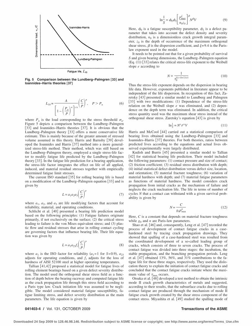
here Pu is the load corresponding to the stress threshold �u.igure 5 depicts a comparison between the Lundberg–Palmgren33� and Ioannides–Harris theories �37�. It is obvious that theundberg–Palmgren theory �33� offers a more conservative lifestimate. This is mainly because of the greater amount of stressedolume assumed in this theory. Harris and Barnsby �39� devel-ped the Ioannides and Harris �37� method into a more general-zed stress-life method. Their method, which was still based onhe Lundberg–Palmgren theory, employed a single stress-life fac-or to modify fatigue life predicted by the Lundberg–Palmgrenheory �33�. In the fatigue life prediction for a bearing application,he stress-life factor integrates the effect on life of all applied,nduced, and material residual stresses together with empiricallyetermined fatigue limit stresses.
The current ISO standard �35� for rolling bearing life is basedn a modification of the Lundberg–Palmgren equation �33� and isiven by
L = a1a2a3�C
P�p
�7�
here a1, a2, and a3 are life modifying factors that account foreliability, material, and operating conditions.
Schlicht et al. �40� presented a bearing life prediction modelased on the following principles: �1� Fatigue failures originaterimarily, if not exclusively on the surface; �2� the critical stresseading to failure is the von Mises equivalent stress; and �3� plas-ic flow and residual stresses that arise in rolling contact cyclingre governing factors that influence bearing life. Their life equa-ion was given by
L = a1a23f t�C
P�p
�8�
here a1 is the ISO factor for reliability �a1=1 for S=0.9�, a23djusts for operating conditions, and f t adjusts for the loss ofardness of AISI 52100 steel at higher operating temperatures.
Tallian �41,42� proposed a statistical model for fatigue lives ofolling element bearings based on a given defect severity distribu-ion. The model used the orthogonal shear stress field as a func-ion of depth below the bearing raceway and computed fatigue lifes the crack propagation life through this stress field according toParis type law. Crack initiation life was assumed to be negli-
ible. The model considered material fatigue susceptibility, fa-igue limiting stress, and defect severity distribution as the main
ig. 5 Comparison between the Lundberg–Palmgren †33‡ andoannides–Harris theories †37‡
arameters. The life equation is given by
41403-4 / Vol. 131, OCTOBER 2009
aded 24 Sep 2009 to 128.46.98.146. Redistribution subject to ASME
ln1
S= �0�2 pmax
�
n0z0�
N�V �9�
Here, �0 is a fatigue susceptibility parameter, �2 is a defect pa-rameter that takes into account the defect density and severitydistribution, n0 is a dimensionless crack growth integral param-eter, z0 is the depth of occurrence of the maximum orthogonalshear stress, � is the dispersion coefficient, and =9.4 is the Paris-law exponent used in the model.
It needs to be pointed out that for a given probability of survivalS and given bearing dimensions, the Lundberg–Palmgren equation�Eq. �1�� �33� relates the critical stress-life exponent to the Weibullslope e according to
N 1
�0��c−h+1�/e� �10�
Thus the stress-life exponent depends on the dispersion in bearinglife data. However, exponents published in literature appear to beindependent of the life dispersion. In recognition of this fact, Za-retsky �43� presented a similar model to Lundberg and Palmgren�33� with two modifications: �1� Dependence of the stress-liferelation on the Weibull slope e was eliminated, and �2� depen-dence on the depth term was eliminated. In addition, the criticalstress quantity used was the maximum shear stress instead of theorthogonal shear stress. Zaretsky’s equation �43� is given by
ln1S = Ne�ceV �11�
Harris and McCool �44� carried out a statistical comparison ofbearing lives obtained using the Lundberg–Palmgren �33� andIoannides–Harris �37� theories. For both theories, ratios betweenpredicted lives according to the equations and actual lives ob-served experimentally were largely distributed.
Kudish and Burris �45� presented a similar model to Tallian�42� for statistical bearing life prediction. Their model includedthe following parameters: �1� contact pressure and size of contact;�2� friction coefficient; �3� residual stress distribution with depth;�4� initial statistical defect distribution versus defect size, location,and orientation; �5� material fracture toughness; �6� variation ofmaterial hardness with depth; and �7� material fatigue parametersas functions of material hardness. The model considers crackpropagation from initial cracks as the mechanism of failure andneglects the crack nucleation life. The life in terms of number ofcycles N that a contact can withstand with a given survival prob-ability is given by
N =C
g0pmaxn �12�
Here, C is a constant that depends on material fracture toughnesswhile g0 and n are Paris-law parameters.
Shao et al. �46� and, consequently, Leng et al. �47� recorded theprocess of development of contact fatigue cracks in a case-hardened steel by tracing crack propagation drawings. Theyshowed that spalling of a case-hardened steel was resulted fromthe coordinated development of a so-called leading group ofcracks, which consists of three to seven cracks. The process ofcontact fatigue was divided into three stages: the incubation, thestable propagation, and the branching propagation periods. Lenget al. �47� obtained 13%, 56%, and 31% contributions to the fa-tigue life for these three stages, respectively. They used the dislo-cation theory to explain the initiation of contact fatigue cracks andconcluded that the contact fatigue cracks initiate where the maxi-mum value of �max occurs.
Otsuka et al. �48� developed a test method to obtain the intrinsicmode II crack growth characteristics of metals and suggested,according to their results, that the subsurface cracks due to rollingcontact fatigue are produced through the mechanism of mode IIfatigue crack growth created by the shear stress component of the
contact stress. Miyashita et al. �49� studied the spalling mode ofTransactions of the ASME
license or copyright; see http://www.asme.org/terms/Terms_Use.cfm

fractfffco
tlpftb
wlriWfcL
rtaHrrsd
msmtRiooe
3C
cpvcHg
atzboH
J
Downlo
ailure under rolling contact fatigue of sintered alloys using theolling contact fatigue tests and finite element model �FEM�nalysis. The location of the ��xy estimated by their FEM analysisoincided with the depth of the crack initiation point observed inheir experiment. Similarly, Otsuka et al. �48� showed that subsur-ace crack growth behavior was controlled by the stress intensityactor range �kII. Also, they concluded considering the surfaceriction force causes the depth of maximum shear stress becomesloser to the contact surface. However, the effect of friction forcen the value of ��xy was not significant.Shimizu �50� showed that bearing steel does not show any fa-
igue limit, whereas structural steel does have a distinct fatigueimit. In the absence of a fatigue limit for bearing steel, a thirdarameter � known as minimum life prior to failure was proposedor the analysis of fatigue life behavior under a given rolling con-act fatigue load, leading to a three-parameter Weibull life distri-ution function
L − � = �C
F�p� ln R
ln 0.9�1/m
�13�
here C is dynamic load capacity, F is equivalent load, p is load-ife component, R is the survival probability of the inner and outerings of bearings, m is Weibull slope, and L is fatigue life. Apply-ng the three-parameter Weibull distribution with a normalized
eibull slope m=10 /9 used in the analysis of a point contactatigue test data for rotary and linear ball bearings, he calculated aonstant value of the load-life exponent p=8 /3 for both L10 and50 lives.Kotzalas �51� investigated the statistical distribution of tapered
oller bearing fatigue lives at high levels of reliability. He showedhat the original two-parameter Weibull distribution cannot predictfinite life value for which 100% of the population will survive.owever, since empirical evidence of a minimum life at 100%
eliability has been shown for through hardened ball and sphericaloller bearings, linear ball bearings, and tapered roller bearings, hehowed that analytical methods using the three-parameter Weibullistribution are able to detect a finite life at high reliability fatigue.
A concise summary of probabilistic engineering bearing lifeodel development is provided in Table 1, in chronological order,
tarting with Palmgren’s �32� seminal work in 1945 to currentodels. Since the engineering models are empirical in nature,
hey offer no significant insights into the physical mechanisms ofCF. On the other hand, the research models are more insightful
n this regard and are attempts to explain some of the mechanismsbserved during the failure process. Section 3 provides a summaryf the research models for estimating the fatigue life of the rollinglements.
Deterministic Research Life Models for Rollingontact FatigueThe deterministic research models are based on physical prin-
iples and take into account the actual mechanics of the failurerocess. Two different sets of models have been traditionally de-eloped to estimate the fatigue lives: �1� models based on therack initiation and �2� models based on the crack propagation.owever, some models account for both the initiation and propa-ation parts of life.
The first analytical approach to study the RCF problem wasdopted by Keer and Bryant �52� who used two-dimensional frac-ure mechanics to evaluate fatigue lives for rolling/sliding Hert-ian contacts. Their approach assumed the crack initiation life toe small in comparison to the crack propagation life. The numberf cycles to failure N was expressed in terms of the maximum
ertzian pressure pmax and the contact half-width b asournal of Tribology
aded 24 Sep 2009 to 128.46.98.146. Redistribution subject to ASME
N =b1−m/2
�0pmaxm �14�
Here, �0 and m are material parameters governing the crackgrowth rate. However, it was found that the fatigue lives calcu-lated using this model were orders of magnitude shorter than thosepredicted for similar Hertzian pressure using engineering models�41�.
Zhou et al. �53,54� introduced a life model that included boththe crack initiation and crack propagation lives. The total life wasexpressed as
N =AWc
��� − 2�k�2D+�
ai
af da
c�Kn �15�
where A, c, and n are material parameters; Wc is the specificfracture energy per unit area; �� is the local shear stress range; �kis the friction stress for the material; D is the damage accumula-tion factor; and �K is the stress intensity factor range at the cracktip.
Bhargava et al. �55� presented a life model based on plasticstrain accumulation in strain hardening materials under cycliccontact stress. The spalling lives were predicted from the plasticstrain. Cheng and co-workers �56,57� proposed a micromechani-cal model based on the dislocation pileup theory to estimate thecrack initiation life in contact fatigue. Microcracks were assumedto be nucleated in slip bands located in material grains. The mi-crocrack initiation life Ni was given by
Ni =c
��� − 2� f�D�16�
where c is a material constant, �� is the critical shear stress am-plitude resolved on the slip layer, � f is a threshold stress below,which cracks do not initiate, and D is a damage accumulationfactor.
Vincent et al. �58� proposed a similar model for crack initiationbased on the dislocation pileup idea. Their model took into ac-count the effect of all stress components and also included re-sidual stress effects. Dislocation emissions were assumed to occurdue to the presence of subsurface inclusions in the bearing steelmatrix that leads to local stress concentrations and local plasticstraining. Inclusions were assumed to be spherical. The number ofcycles to crack initiation N was found according to the followingequation:
�
��1 − ���pl + 2fN�pc�
d
2�ln1
8���pl + 2fN�pc�
d
b��2 −
�x + �y
2
=�
��17�
Here, � and are the shear moduli and Poisson’s ratio for thematrix, f is a damage efficiency accumulation factor, d is theinclusion diameter, � is the length of the domain in which dislo-cations are accumulated, �pl is the effective plastic strain after thefirst loading cycle, �pc is the effective plastic cyclic strain, b� isthe modulus of Burgers’ vector, �x and �y are components of thestress tensor, which include the Hertzian as well as residualstresses, and � is the theoretical strength factor of the order of 5for most metals. Xu and Sadeghi �59� developed an analyticalmodel to investigate the effects of dent on spall initiation andpropagation in lubricated contacts. Their model was based on thedamage mechanics concept that the fatigue spall initiation andpropagation is due to the accumulated plastic strain process ratherthan the stress intensity at the tip of the crack.
Lormand et al. �60� extended the model of Vincent et al. �58� toinclude crack propagation according to a Paris law. Crack growth
was assumed to occur due to shear stresses �mode II propagation�.OCTOBER 2009, Vol. 131 / 041403-5
license or copyright; see http://www.asme.org/terms/Terms_Use.cfm

0
Downlo
Table 1 A chronological listing of probabilistic engineering bearing life prediction model development
Year Researchers Ref. Model description/hypothesis
1945 Palmgren �32� Empirical.1947 Lundberg and Palmgren �33� First probabilistic bearing life model, termed the LP
model, based on probability of crack initiation at asubsurface depth �z0� where orthogonal shear stress ��0�is maximum in stressed volume �V� in the contact,expresses the probability of survival �S� after N RCFcycles as �Eq. �1��: ln�1 /S�=A�Ne�0
cV /z0h�, where A, c,
and h are experimentally determined material parametersand e is the Weibull slope for the experimental life data.The L10 life �Eq. �3�� is expressed as L10= �C / P�p, whereC is the bearing basic dynamic load rating, P is theequivalent load acting on the bearing, and exponent pdepends on contact shape.
1952 Lundberg and Palmgren �34�
1971 Chiu et al. �36� Probabilistic model �Eq. �4�� that attributes spalling tointrinsic material defects and includes influence ofmaterial elastic and plastic properties, defect type,concentration, and geometry on the contact stress field
via factors �i, given by ln�1 /S�= � �i=0
4
�i�N�. �=dispersion
coefficient.1985 Ioannides and Harris �37� Improves on the LP model by �i� assuming discrete
material volumes, each with its own probability ofsurvival, and overall risk obtained by integration; and �ii�introducing a stress threshold ��u� below which nofailure is possible, resulting in the following relation �Eq.�5��:
ln�1/S� = ANe V
�� − �u�c
zh dV, � � �u.
1986 Schlicht et al. �40� Model assumes that fatigue failures originate at thesurface due to von Mises stress, and plastic flow andresidual stress development due to RCF influencebearing life. The life model is given by L=a1a23f t�C / P�p
where a1 and a23 are life modifying factors based onreliability, material, and operating conditions.
1987 Shao et al. �46� The development of cracks due to RCF in case-hardenedbearing steels was described by a three-stage process:incubation, stable propagation, and branching/propagation.
1988 Leng et al. �47� The three stages described in Ref. �46� were allocated13%, 56% and 31% contributions to life.
1989 Current ISO Standard �35� The life relation is given by L=a1a2a3�C / P�p, where ai
are life modifying factors.1992 Tallian 41 and 42 Probabilistic life model uses orthogonal shear stress field
solution in conjunction with a Paris-law exponent ���and growth parameters �n0�, material fatiguesusceptibility ��0�, and defect ��2� parameters, given by�Eq. �9��: ln�1 /S�=�0�2�pmax
� /n0z0��N�V.1994 Zaretsky �43� Life equation �Eq. �11�� is ln�1 /S�=Ne�ceV and is similar
to LP model, with two modifications: �i� dependence ofthe stress-life relation on the Weibull slope e waseliminated, and �ii� dependence on the depth term waseliminated. �ce is the maximum shear stress and notorthogonal shear stress.
1996 Harris and McCool �44� Statistical comparison of actual and computed bearinglives from LP and Ioannides and Harris’s �37� modelsshowed wide dispersion.
1996 Otsuka et al. �48� RCF testing and FEA showed that subsurface crackgrowth behavior was controlled by mode II stressintensity range, �KII.
1999 Ioannides et al. �38� The load-life relation, incorporating model in Ref. �37�,is given by Eq. �6� as
L10 = �A/1 − �Pu
P�wc/e��C
P�p
, P � Pu,
where Pu is the load corresponding to �u.2000 Kudish and Burris �45� Model improved by Tallian �41,42� by including the
effects of contact pressure and size, friction coefficient,residual stresses, initial defect, size, location andorientation distributions, material fracture toughness,material hardness variation with depth, and materialfatigue parameters as function of hardness.
41403-6 / Vol. 131, OCTOBER 2009 Transactions of the ASME
aded 24 Sep 2009 to 128.46.98.146. Redistribution subject to ASME license or copyright; see http://www.asme.org/terms/Terms_Use.cfm

Hn�
wlwbaRqa
setmfss
mwuswanc
waFt
wsacdsPn�sc
J
Downlo
owever, in order to account for the compressive stress compo-ent �n acting along the crack faces, a Coulomb friction stress61� given by
�eff = �� − c�n� �18�
as assumed. A coefficient of friction c=0.4 �used also by Me-ander �62�� was chosen although no justification for this valueas provided. Later, Lormand et al. �63� applied a new physicallyased model to determine the influence of inclusion populationnd loading conditions on the distribution of rolling bearing lives.ecently, in order to estimate the rolling contact fatigue range anduality control of bearing steel, Girodin et al. �64� did a statisticalnalysis of nonmetallic inclusions.
Harris and Yu �65� showed that application of surface sheartresses in combination with Hertz stresses can significantly influ-nce the subsurface octahedral shear stress distribution. However,hey concluded that such surface shear stresses do not alter the
aximum range of the subsurface orthogonal shear stress. There-ore they suggested using the octahedral shear stress �von Misestress� as the failure-causing stress in fatigue life prediction analy-es.
Jiang and Sehitoglu �66� applied an elastoplastic finite elementodel that included the effects of cyclic ratcheting in conjunctionith a multiaxial fatigue criterion �67� to compute the total lifender rolling line contacts. Total damage D was assumed to be aum of damage due to fatigue Df and due to ratcheting Dr. Failureas assumed to occur when the total damage equaled unity. This
pproach was again based only on the crack initiation life andeglected the crack propagation aspect. The rates of damage ac-umulation for the two phenomena were given by
dDf
dN=
�FP − FP0�m
C,
dDr
dN=
�d�r
dN�
�crict�19�
here FP is a fatigue parameter; �r is the ratcheting strain FP0;nd m, C, and �crict are material constants. The fatigue parameterP was related to stresses and strains on a critical plane according
o the following multiaxial fatigue criterion �67�:
FP =��
2�max + J���� �20�
here �� is the normal strain range, �max is the maximum normaltress, �� is the shear strain range, �� is the shear stress range,nd J is a material dependent constant. They concluded that theombination of fatigue and ratcheting damage is maximum at aepth corresponding to the occurrence of maximum orthogonalhear stress range. This is in accordance with the Lundberg–almgren theory �33�. Ringsberg �68� combined elastic-plastic fi-ite element analyses, multiaxial fatigue crack initiation model67� used together with the critical plane concept, fatigue damageummation calculations, and comparison of results from numeri-
Table 1
Year Researchers Ref.
2002 Shimizu �50�
2003 Miyashita et al. �49�
2005 Kotzalas �51�
al analyses and experiments to develop a strategy for fatigue life
ournal of Tribology
aded 24 Sep 2009 to 128.46.98.146. Redistribution subject to ASME
prediction of rolling contact fatigue crack initiation. He concludedthat the strategy developed has the capacity to predict the positionfor greatest fatigue damage, the orientation of crack planes, andthe fatigue life to crack initiation due to both low-cycle fatigueand ratcheting. Multiaxial fatigue damage due to RCF using thecritical plane approach, with applications to railway wheel contactfatigue, is addressed by Liu et al. �69� and Liu and Mahadevan�70�. Table 2 provides a concise summary of the deterministicmodels, in chronological order.
4 Limitations of Existing Life ModelsThe research models proposed in literature are based on a ho-
mogeneous description of material in the contact region to esti-mate the contact fatigue life. Such homogeneous material descrip-tion overlooks the inhomogeneities such as nonmetallic inclusionsthat are invariably present in the contact region as byproducts ofthe bearing manufacturing methods, as shown, for example, inFig. 6 �from Ref. �71��. These inclusions often act as nucleationsites for the fatigue cracks �72,73�. The inclusions not only causeearly damage due to their inferior strength properties but alsocause local stress concentrations owing to their differential con-stitutive properties in relation to the surrounding matrix �74,75�.In addition, nonmetallic inclusions cause stress induced micro-structural alterations in the surrounding matrix under cyclic load-ing �76,77�. These structural changes assist in the fatigue process.Two commonly structural changes occurring under the raceway inrolling element bearings are the “butterfly” effect as shown in Fig.7 �from Refs. �78,79��, and slip bands as shown in Fig. 8 �fromRef. �79��.
Very few models relate the micromechanical material behaviorto the phenomenon of RCF. The first fatigue cracks invariablyappear as microcracks at weak material points, and the crack ini-tiation mechanism is influenced by the microscopic characteristicsof the material. Therefore, the models that are based on a macros-cale description of the material tend to overlook the microscopicdetails. Rolling contact fatigue lives of bearings are known toshow scatter because of the spatial dispersion in material strengthsand inclusion distributions. In fact, experimentally observed bear-ing lives follow the Weibull distribution closely. The process ofcrack initiation is essentially one of seeking the weakest point inthe material where the local strength is a minimum. However, theanalytical models proposed in literature are deterministic in natureand hence do not take this into account. Also, from experimentalevidence, the material properties under contact fatigue are nonuni-form but vary along different subsurface layers �56�. This is an-other aspect that is overlooked in previous analytical models.
On the other hand, in the engineering life models, differentcritical stress criteria have been proposed to be used in the lifeequation. These include the orthogonal shear stress �33�, the maxi-mum shear stress �80�, the von Mises stress �37�, and the octahe-dral shear stress �54�. Note that the maximum value of each stress
ntinued.…
Model description/hypothesis
A three-parameter Weibull life distribution function wasproposed, after showing that bearing steels subject to RCF donot exhibit a fatigue endurance limit, given by �Eq. �13�� L−�= �C /F�p�ln R / ln 0.9�1/m, where � is the minimum lifeprior to failure.The location of ��xy estimated by FEA was shown tocoincide with the depth of crack initiation observed in RCFexperiments using sintered alloys.A three-parameter Weibull distribution was shown to be ableto predict finite life in the high reliability regime, based onstatistical distribution of tapered roller bearings.
„Co
measure occurs at different depths below the surface in a bearing
OCTOBER 2009, Vol. 131 / 041403-7
license or copyright; see http://www.asme.org/terms/Terms_Use.cfm

cdmlmtmbve
mla
0
Downlo
ontact and is different in magnitude. Hence, each criterion pre-icts a different depth where crack initiation could occur. Experi-entally, cracks have been found to initiate at various depths be-
ow the contact surface �81–83�. Therefore, the exact stresseasure governing crack initiation under rolling contact condi-
ions is not clear yet. Moreover, calibration of the engineering lifeodels requires extensive RCF endurance testing that becomes
oth expensive and time consuming. From a practical point ofiew, a model with a few input parameters that can be calibratedasily using simple and inexpensive bench tests is desired.
In view of the limitations of the current state of bearing lifeodeling, some modeling approaches, for predicting the fatigue
ives of the rolling element bearings, recently proposed by the
Table 2 A chronological listing of deterministic
Year Researchers Ref.
1983 Keer and Bryant �52�
1989 Zhou et al. �53�
1990 Bhargava et al. �55�
1992 Sehitoglu and Jiang �67�1993 Zhou �54�1994 Cheng et al. �56�
1995 Cheng and Cheng �57�
1997 Melander �62�
1998 Vincent et al. �58�
1998 Lormand et al. �60�
1999 Harris and Yu �65�
1999 Jiang and Sehitoglu �66�
2001 Ringsberg �68�
2006 Liu et al. �69�
2007 Liu and Mahadevan �70�
research bearing life prediction model development
Model description/hypothesis
First deterministic analysis of RCF life. A 2D fracturemechanics approach is used for life estimation inrolling/sliding Hertzian cylindrical contacts assuminginitiation life is small compared with propagation life.Cycles to failure N=b1−m/2 /�0pmax
m , where pmax ismaximum Hertz pressure, b is contact half-width, and �0and m are crack growth parameters. Life computedgreatly underpredicted compared with LP-based models.Model included both crack initiation and propagationlives. The total life is �Eq. �15�� N=AWc / ���−2�k�2D+ ai
af�da /c�Kn�, where A, c, and n are materialparameters; �k is the specific fracture energy per unitarea; Wc is material friction stress; D is the damageaccumulation factor; and �K is the stress intensity factorrange at the crack tip.Model based on plastic strain accumulation in strainhardening materials under cyclic RCF.Multiaxial fatigue crack initiation model for RCF.Extension to model in Ref. �53�.Micromechanical model based on dislocation dynamics�pileup�. Crack nucleation was assumed to take place inslip bands at the grain level. Initiation life is given by�Eq. �16�� �Ni= �c / ���−2� f�D��, where �� is the criticalshear stress amplitude and � f is a threshold.A FEA study of cracks subjected to RCF including crackface friction due to closure.Crack initiation model based on dislocation pileup andaccounted for full stress tensor and residual stress field.Dislocation emissions were assumed to occur due to thepresence of subsurface inclusions that lead to stressconcentration and localized slip/plasticity.Extension of model in Ref. �58� to include crackpropagation via Paris law, driven by mode II loading. ACoulomb stress was included to account for crack facefriction due to closure.The inclusion of surface traction along with Hertziannormal pressure was shown to significantly increasesubsurface octahedral shear stress �von Mises stress�, butnot the maximum stress range.Elastic-plastic FEA that included effects of ratchetingunder RCF in conjunction with a multiaxial fatiguedamage criterion was used to compute initiation life forline contacts �Eqs. �19� and �20��. Maximum damagecorresponded to depth where orthogonal shear stressrange was maximum, in accordance with LP theory.Elastic-plastic FEA, multiaxial fatigue crack initiationmodel based on a critical plane approach, and fatiguedamage accumulation concepts were used to develop aprocedure for life prediction under RCF loading.Multiaxial fatigue damage due to RCF using the criticalplane approach, with applications to railway wheelcontact fatigue.A unified multiaxial fatigue damage model for RCFusing the critical plane approach for isotropic andanisotropic materials.
uthors are summarized in Sec. 5. The new approaches investigate
41403-8 / Vol. 131, OCTOBER 2009
aded 24 Sep 2009 to 128.46.98.146. Redistribution subject to ASME
Fig. 6 Subsurface inclusions in bearing steel AISI-52100 †71‡
Transactions of the ASME
license or copyright; see http://www.asme.org/terms/Terms_Use.cfm

ttcacpmetmawmIgns
rmecateccpmo
Fub
J
Downlo
he RCF problem from a different viewpoint, by treating the ma-erial in the contact region as a nonhomogeneous microstructureonsisting of randomly shaped, sized, and oriented structures thatre sized to be the same as a grain in bearing material. This mi-rolevel modeling is motivated by the fact that at some level, allhysical materials are discontinuous. Commercially used bearingaterials, including bearing steels and bearing grade ceramics,
xhibit a granular microstructure �84� with average grain sizes ofhe order of 1–10 �m. These materials have a nonhomogeneousicrostructure at the micron level, where the grain boundaries can
ct as physical discontinuities in the system. In bearing contactshere the characteristic length scale is of the order of hundreds oficrons, the microstructural length scale is no longer negligible.
n these cases, it is reasonable to look at the material domain as aranular matrix. Better understanding of the microscopic mecha-isms of failure can be obtained through such analyses whereome of the microgeometric material features are included.
The proposed approaches offer several advantages over existingesearch models for RCF life. First, they are based on a nonho-ogeneous description of the material. In this regard, they can
asily incorporate the effects of material inclusions in bearingontacts. Second, unlike the crack propagation approachesdopted in literature where some initial crack geometry and loca-ion are assumed, the present approaches do not require the pres-nce of initial cracks or flaws in the material domain. In fact,racks can be naturally initiated under the contact loading and canontinue to grow if the stress conditions permit. Third, instead ofresuming a Weibull slope, the new approaches are capable ofodeling the scatter in crack initiation and propagation lives and
ig. 7 Formation of butterflies around nonmetallic inclusionnder rolling contact: „a… bearing steel AISI-52100 †78‡, and „b…earing steel M50 074A †79‡
btaining the Weibull slope as an output of simulations. Finally,
ournal of Tribology
aded 24 Sep 2009 to 128.46.98.146. Redistribution subject to ASME
the models have the potential to offer more insight into the physi-cal mechanism of the failure process occurring during RCF.
5 Computational Models for Rolling Contact FatigueAs mentioned earlier, Lundberg and Palmgren �34� applied the
Weibull weakest link theory to formulate an empirical life formula�Eq. �1�� for bearing lives. The scatter in bearing lives was takeninto account through the parameter e that represents the Weibullslope for experimentally observed bearing lives. As shown inSecs. 2 and 3, Ioannides and Harris �37�, Zhou �53�, Zaretsky�43�, and Cheng and Cheng �57� proposed similar empirical mod-els to Lundberg and Palmgren �33�. The underlying idea in thedevelopment of the empirical life models is a direct application ofthe Weibull strength theory without explicit incorporation of thematerial microstructural characteristics. In other words, it is as-sumed that the lives follow a Weibull distribution, rather than theresultant life distribution being an outcome of the inhomogeneousand random nature of the material microstructure. Raje et al. �85�presented a statistical model to estimate life scatter in rolling el-ement bearings that took the material microstructure explicitlyinto account. Their modeling approach is based on a discreterather than a continuous representation of the material in the bear-ing contact region �86,87�. The semi-infinite domain constitutingthe subsurface region in the bearing line contact is assumed to beformed by an assemblage of discrete, interacting, micro-elements,as shown in Fig. 9. These micro-elements are connected alongtheir contacting sides through fibers to form compliant joints �Fig.10�a��. Loads applied on the boundary of the domain are trans-ferred to the internal elements through deformation of these joints.As shown in Fig. 10�b�, each interelement joint comprises of both
Fig. 8 Cross section of M50 Bearing 216 slightly past the spal-led area showing slip bands: „a… circumferential cross section,and „b… circumferential cross section at higher magnification†79‡
normal and tangential fiber sets, so that elements can overlap in
OCTOBER 2009, Vol. 131 / 041403-9
license or copyright; see http://www.asme.org/terms/Terms_Use.cfm

tbTnd�tmsmmsfi
lbWagerrsd
Ff
0
Downlo
he normal direction as well as slide relative to each other. Thus,oth normal and shear tractions are transferred between elements.he fibers are assumed to be linear-elastic, and the fiber stiff-esses, namely, Kn in the normal direction and Kt in the tangentialirection, are related to the macroscopic elastic properties E and 86�. By assigning unique fiber stiffnesses to each joint, the ma-erial domain can be made nonhomogeneous. Due to the interele-
ent connectivity, the overall material domain behaves as aingle, deformable body. The stress fields in such a discontinuousaterial domain are obtained through the solution of equations ofotion for each element independently. Details of the solution
cheme and the discrete element model used to obtain the stresseld can be found in Ref. �86�.It is hypothesized that it is the variation in the magnitude and
ocation of the critical stress quantity that leads to scatter in theearing fatigue life. The model does not explicitly assume aeibull distribution of fatigue lives. Rather, the life distribution is
n outcome of numerical simulations performed using statisticallyenerated material microstructures. The microstructures are gen-rated using the process of Voronoi tessellation. Two sources ofandomness in the material are considered: �1� the topologicalandomness due to geometric variability in the material micro-tructure and �2� material property randomness due to a statistical
ig. 9 „a… Discrete representation of the semi-infinite domainorming the bearing line contact; „b… zoomed view
istribution of material properties spatially throughout the mate-
41403-10 / Vol. 131, OCTOBER 2009
aded 24 Sep 2009 to 128.46.98.146. Redistribution subject to ASME
rial. The fatigue life N is assumed to be related to the criticalstress and the corresponding depth quantities by a relation of theform
N �zr
�q �21�
However, an explicit Weibull life distribution is not assumed; i.e.,the equation is independent of the Weibull slope e. Instead, thecritical stress and depth quantities � and z are assumed to be thevariable parameters that lead to variability in life. This variationoccurs due to randomness in the material microstructural charac-teristics. For convenience, the exponents q and r are assumed tobe the same as the exponents c and h in the original Lundberg–Palmgren theory �33�. It is assumed that fatigue damage occursalong internal planes of weakness that are subjected to alternateshear stressing. Fatigue damage first starts along planes that expe-rience the maximum range of alternating shear stress during theloading cycle. This is in accordance with several multiaxial fa-tigue criteria proposed in literature �25,27�. Figure 11 illustratesthe effect of variable number of internal flaws on life distribution.It was found that lives are distributed according to a two-parameter Weibull distribution with Weibull slopes ranging from1.29 to 3.36. Similarly, there is a reduction in the Weibull slope ewith increasing number of flaws. Further, the results reach a lim-iting value beyond which there is no change in the Weibull slopewith further increase in number of flaws, as observed in Fig. 12.The limiting value of e is found to be 1.29, which is close to thevalue of 1.125 used in the Lundberg–Palmgren theory �33�.
Jalalahmadi and Sadeghi �88� proposed a new Voronoi finiteelement method �VFEM� using the Voronoi tessellation to simu-late the material microstructure and its effects on rolling contactfatigue. In their model, a fatigue life criterion similar to Raje et al.�85� �Eq. �21�� was adopted, but instead of employing the discreteelement method �DEM�, they used the Voronoi finite elementmethod as the numerical model to investigate the effects of mate-rial microstructure on rolling contact fatigue. Again, unlike theLundberg–Palmgren theory �33� an explicit Weibull life distribu-tion was not assumed, instead the critical stress and its depth were
Fig. 10 „a… Interelement contact in the discrete model; „b… fibermodel
assumed to be the variable parameters, occurring because of the
Transactions of the ASME
license or copyright; see http://www.asme.org/terms/Terms_Use.cfm

rtmuTutmriat
Fo
Fs
J
Downlo
andom shape and size of grains in the material microstructurehat lead to variability in the life. They considered both the maxi-
um range of octahedral shear stress ���xy� and the maximumnidirectional shear stress ��max� as the critical stress quantities.hey studied the effects of material microstructure topology, non-niform elastic properties, and initial flaws on rolling contact fa-igue. The Weibull slopes of the fatigue lives calculated by their
odel agreed with the experimental works �89� and the analyticalesults �85�. They showed that considering material inhomogene-ty using elastic modulus variation and initial flaws increased theverage value of the critical stresses and changed the depths rela-ive to the values obtained for the homogeneous domains. How-
ig. 11 Life distributions in the presence of variable numberf flaws
ig. 12 Effect of internal flaws on „a… L10 life and „b… Weibull
lope eournal of Tribology
aded 24 Sep 2009 to 128.46.98.146. Redistribution subject to ASME
ever, the average value and range of depths remain relatively thesame for both homogeneous and inhomogeneous domains. Ac-cording to their results, introducing both inhomogeneous materialproperties and initial cracks into the domains reduced the fatiguelives and increase their scatter. A general reference for the prop-erties of Voronoi tessellation is given by Okabe and Boots �90�and a more mathematical one by Moller �91�.
The model presented in Ref. �85� was restricted to predictingonly the life distributions and not the absolute lives. It was furtherimproved upon in Ref. �92� by coupling it with a damage mechan-ics based fatigue model to explicitly take into account the gradualmaterial degradation that occurs under rolling contact cycling.Damage was incorporated through an internal damage variable Dand was implemented through degradation of the joint spring stiff-nesses. Figure 13 shows the degradation of joint stiffnesses undercyclic loading. Damage evolution is assumed to occur accordingto an equation of the following form:
dD
dN= ��
�r�1 − D�m
�22�
Here, �� is the shear stress range acting along the interelementjoint. The parameters �r and m are material parameters that aredetermined from torsional fatigue tests according to the followingequations:
m = B, �r = 2� f�B + 1�1/B �23�
Here, B is the slope of the torsional S-N curve for the material and� f is known as the torsional fatigue strength coefficient, which isalso determined from the torsional S-N curve. A microcrack wasassumed to be initiated at an interelement joint when the accumu-lated damage in it equaled unity �D=1�. The process of spallingwas modeled through growth of damaged zones in the material.Final failure is defined when a crack reaches the surface. Figure14 shows a sample spall formation process. Spall formation ismanifested through several distinct cracks rather than a singlecrack as assumed in models based on fracture mechanics �49,93�.This observation has been made experimentally by several re-searchers using metallographic examinations of spalled sections
Fig. 13 Degradation of joint stiffnesses with damage accumu-lation: „a… normal direction and „b… tangential direction
of contacting elements �14,46,47,81�.
OCTOBER 2009, Vol. 131 / 041403-11
license or copyright; see http://www.asme.org/terms/Terms_Use.cfm

lapciw2iota1
Fc„
Ã
m
0
Downlo
Figure 15 depicts the variation of the initiation and propagationives for multiple material domains. The initiation life is defineds the number of cycles elapsed before the first microcrack ap-ears. The subsequent number of cycles before a surface breakingrack forms constitutes the propagation life. It is observed that thenitiation phase of fatigue life is a small fraction of the total life,ith the average initiation life for the 40 domains being about0% of their total life. In relation to the total fatigue lives, thenitiation lives do not show much scatter between domains and theverall scatter in the total lives is primarily governed by the scat-er in propagation lives. The Weibull slopes �e� for the initiationnd total lives using a two-parameter Weibull fit are 11.75 and
ig. 14 Formation of subsurface initiated spall through micro-rack initiation and coalescence: „a… first microcrack initiated11.84Ã106 cycles…, „b… multiple microcracks initiated „14.83
106 cycles…, and „c… multiple crack coalescence and spall for-ation „123.25Ã106 cycles…
.85, respectively. However, the total lives are found to follow a
41403-12 / Vol. 131, OCTOBER 2009
aded 24 Sep 2009 to 128.46.98.146. Redistribution subject to ASME
three-parameter Weibull distribution more closely. Figure 16shows the stress-life curve obtained from model simulations.Here, the L10 lives are plotted against the contact pressure pmax.Table 3 shows the corresponding stress-life exponents obtainedfrom the model and compares them with those obtained fromother models in literature.
Recently, Raje and Sadeghi �94� developed a statistical lifeequation for subsurface initiated spalling of bearing elementsbased on the life distributions and the stress-life results obtainedthrough their simulations. They showed that the spalling lives fol-low a three-parameter Weibull distribution closely. Using the gen-eral equation for the three-parameter Weibull distribution and theirsimulation results, they expressed the spalling life N as
Fig. 15 Weibull life plots for different material domains withconstant material properties
Fig. 16 Variation of L10 life with contact pressure
Table 3 Comparison of stress-life exponents for line contacts
Source Stress-life exponent
Raje et al. �92� �two-parameter Weibull estimate� 8.93Raje et al. �92� �three-parameter Weibull estimate� 9.38Lundberg and Palmgren �33� 8Poplawski et al. �95� 9.9
Transactions of the ASME
license or copyright; see http://www.asme.org/terms/Terms_Use.cfm

wifWmsPa
Fi��ftt1aa
6
eRpagsoe
S
R
L�
Fp
J
Downlo
ln�1
S� =
1
B1e · pmax
e�f−d� · Ne · �pmaxd −
A1
N�e
�24�
here pmax is maximum Hertzian contact pressure, S is probabil-ty of survival, e is Weibull parameter, d is power law exponentor Weibull minimum life parameter, f is power law exponent for
eibull scale parameter, A1 is power law constant for Weibullinimum life parameter, and B1 is power law constant for Weibull
cale parameter. Moreover, they rearranged the Lundberg–almgren equation �Eq. �1�� �33� in terms of the contact pressures
ln�1
S� = M1 · pmax
c−h+1 · Ne �25�
rom Eqs. �24� and �25�, it can be observed that their life equations similar in form to the original Lundberg–Palmgren equation33�, with a modification term. In the absence of a minimum lifei.e., using a two-parameter Weibull fit�, Eq. �24� reduces to aorm similar to Eq. �25�. Table 4 lists the two equations usingwo-parameter Weibull values obtained from their simulations andhe original values used by Lundberg and Palmgren �33�. Figure7 depicts the comparison between these two life equations usingprobability of survival equal to 0.9. As observed there is a good
greement between the two life models.
SummaryRCF is the most unavoidable mode of failure of ball and rolling
lement bearings. There are two most dominant mechanisms forCF, i.e., the subsurface originated spalling and surface originateditting. In this paper, a review of the most acceptable empiricalnd research models, existing in literature, developed for investi-ating the rolling contact fatigue caused by subsurface originatedpalling was provided. Tables 1 and 2 provide a concise summaryf the empirical and research models, respectively. Though thempirical models are practical life prediction tools, they do not
Table 4 Comparison of life equations
ource Life equation
aje and Sadeghi �94� N =39354
pmax8.74 ln�1
S�0.58
undberg–Palmgren theory �33�c=10.33, h=2.33, e=1.125, M1=4.056�10−6� N =
62037
pmax8 ln�1
S�0.88
ig. 17 The comparison between two life equations using a
robability of survival equal to 0.9ournal of Tribology
aded 24 Sep 2009 to 128.46.98.146. Redistribution subject to ASME
take the material microstructure explicitly into account. The un-derlying idea in the development of the empirical life models is adirect application of the Weibull strength theory without explicitincorporation of the material microstructural characteristics. Inother words, it is assumed that the lives follow a Weibull distri-bution, rather than the resultant life distribution being an outcomeof the inhomogeneous and random nature of the material micro-structure. On the other hand, the research models are based on ahomogeneous description of the material in the contact region toestimate the contact fatigue life. However, subsurface initiatedspalling, which is the classical mode of failure in rolling elementbearings that operate under conditions of EHL, is significantlyinfluenced by the material microstructure, which is inherently in-homogeneous due to the presence of defects and nonuniform dis-tribution of material properties. As a result of these inhomoge-neous material microstructures, spalling lives of a seeminglyidentical batch of bearings operating under identical load, speed,lubrication, and environmental conditions show a significant de-gree of scatter.
In view of the limitations of the current state of bearing lifemodeling, some research models recently proposed by the authors,in order to predict the fatigue lives of the rolling element bearings,were reviewed. The new approaches, including DEM �85� andVFEM �88�, investigate the RCF problem from a different view-point, by treating the material in the contact region as a nonho-mogeneous microstructure consisting of randomly shaped, sized,and oriented grains. Contrary to the Lundberg–Palmgren theory�33�, the developed models hypothesized that it is the variation inthe magnitude and location of the critical stress quantity that leadsto scatter in the bearing fatigue life. The models do not explicitlyassume a Weibull distribution of fatigue lives. Rather, the lifedistribution is an outcome of numerical simulations performedusing statistically generated material microstructures. The micro-structures are generated using the process of Voronoi tessellation.Also, the DEM model was further extended �92� by coupling itwith a damage mechanics based fatigue model to explicitly takeinto account the gradual material degradation that occurs underrolling contact cycling. As a result, not only the life distributions,but also the absolute lives of bearings could be predicted. It wasobserved that the Weibull slopes for the fatigue lives and the fa-tigue crack initiation depths, obtained using the models, agreewith the experimental works �82,89�. Moreover, based on the sta-tistical distribution of spalling lives and the resultant stress-liferesults, a new life equation was proposed �94�, which is similar instructure to the original Lundberg–Palmgren equation �33� with amodification term.
References�1� Voskamp, A. P., Osterlund, R., Becker, P. C., and Vingsbo, O., 1980, “Gradual
Changes in Residual Stress and Microstructure During Contact Fatigue in BallBearings,” Met. Technol. �London�, 7, pp. 14–21.
�2� Osterlund, R., and Vingsbo, O., 1980, “Phase Changes in Fatigued Ball Bear-ings,” Metall. Trans. A, 11, pp. 701–707.
�3� Voskamp, A. P., 1985, “Material Response to Rolling Contact Loading,”ASME J. Tribol., 107, pp. 359–366.
�4� Voskamp, A. P., 1998, “Fatigue and Material Response in Rolling Contact,”Bearing Steels: Into the 20th Century, ASTM STP No. 1328, ASTM SpecialTechnical Publication, West Conshohocken, PA, pp. 152–166.
�5� Voskamp, A. P., and Mittemeijer, E. J., 1997, “The Effect of the ChangingMicrostructure on the Fatigue Behavior During Cyclic Rolling Contact Load-ing,” Z. Metallkd., 88, pp. 310–319.
�6� Hahn, G. T., Bhargava, V., and Chen, Q., 1990, “The Cyclic Stress-StrainProperties, Hysteresis Loop Shape, and Kinematic Hardening of Two High-Strength Bearing Steels,” Metall. Trans. A, 21, pp. 653–665.
�7� Voskamp, A. P., 2002, “Microstructural Stability and Bearing Performance,”Bearing Steel Technology, ASTM STP No. 1419, ASTM Special TechnicalPublication, West Conshohocken, PA, pp. 443–456.
�8� Voskamp, A. P., Nierlich, W., and Hengerer, F., 1997, “X-Ray DiffractionProvides Answers to Bearing Failures,” SKF Evolution, 4, pp. 25–31.
�9� Voskamp, A. P., and Mittemeijer, E. J., 1997, “State of Residual Stress Inducedby Cyclic Rolling Contact Loading,” Mater. Sci. Technol., 13, pp. 431–438.
�10� Turteltaub, S., and Suiker, A. S. J., 2005, “Transformation-Induced Plasticityin Ferrous Alloys,” J. Mech. Phys. Solids, 53, pp. 1747–1788.
�11� Voskamp, A. P., and Mittemeijer, E. J., 1996, “Crystallographic Preferred Ori-
OCTOBER 2009, Vol. 131 / 041403-13
license or copyright; see http://www.asme.org/terms/Terms_Use.cfm
0
Downlo
entation Induced by Cyclic Rolling Contact Loading,” Metall. Mater. Trans. A,27, pp. 3445–3465.
�12� Littmann, W. E., and Widner, R. L., 1966, “Propagation of Contact FatigueFrom Surface and Sub-Surface Origins,” ASME J. Basic Eng., 88, pp. 624–636.
�13� Littmann, W. E., 1969, “The Mechanism of Contact Fatigue,” NASA, SpecialReport No. SP-237.
�14� Lou, B., Han, L., Lu, Z., Liu, S., and Shen, F., 1990, “The Rolling ContactFatigue Behaviors in Carburized and Hardened Steel,” Fatigue 90: Proceed-ings of the Fourth International Conference on Fatigue and Fatigue Thresh-olds, Honolulu, HI, H. Kitagawa and T. Tanaka, eds., pp. 627–632.
�15� Bower, A. F., 1988, “The Influence of Crack Face Friction and Trapped Fluidon Surface Initiated Rolling Contact Fatigue Cracks,” ASME J. Tribol., 110,pp. 704–711.
�16� Nelias, D., Dumont, M. L., Champiot, F., Vincent, A., Girodin, D., Fougeres,R., and Flamand, L., 1999, “Role of Inclusions, Surface Roughness and Op-erating Conditions on Rolling Contact Fatigue,” ASME J. Tribol., 121�2�, pp.240–251.
�17� Hertz, H., 1882, “On the Contact of Elastic Solids,” J. Reine Angew. Math.,92, pp. 156–171.
�18� McEwen, E., 1949, “Stresses in Elastic Cylinders in Contact Along a Genera-trix,” Philos. Mag., 40, pp. 454–459.
�19� Poritsky, H., 1950, “Stresses and Deflections of Cylindrical Bodies in Con-tact,” ASME J. Appl. Mech., 17, pp. 191–201.
�20� Smith, J. O., and Liu, C. K., 1953, “Stresses Due to Tangential and NormalLoads on an Elastic Solid,” ASME J. Appl. Mech., 20, pp. 157–166.
�21� Sackfield, A., and Hills, D. A., 1983, “Some Useful Results in the ClassicalHertz Contact Problem,” J. Strain Anal., 18, pp. 101–105.
�22� Sackfield, A., and Hills, D. A., 1983, “Some Useful Results in the TangentiallyLoaded Hertz Contact Problem,” J. Strain Anal., 18, pp. 107–110.
�23� Sackfield, A., and Hills, D. A., 1983, “A Note on the Hertz Contact Problem:Correlation of Standard Formulae,” J. Strain Anal., 18, pp. 195–197.
�24� Johnson, K. L., 1985, Contact Mechanics, Cambridge University, Cambridge.�25� McDiarmid, D. L., 1991, “A General Criterion for High Cycle Multi-Axial
Fatigue Failure,” Fatigue Fract. Eng. Mater. Struct., 14, pp. 429–453.�26� McDiarmid, D. L., 1994, “A Shear Stress Based Critical-Plane Criterion of
Multiaxial Fatigue Failure for Design and Life Prediction,” Fatigue Fract. Eng.Mater. Struct., 17, pp. 1475–1484.
�27� Susmel, L., and Lazzarin, P., 2002, “A Bi-Parametric Wohler Curve for HighCycle Multi-Axial Fatigue Assessment,” Fatigue Fract. Eng. Mater. Struct.,25�1�, pp. 63–78.
�28� Papadopoulos, I. V., 1995, “A High-Cycle Fatigue Criterion Applied in Biaxialand Triaxial Out-of-Phase Stress Conditions,” Fatigue Fract. Eng. Mater.Struct., 18, pp. 79–91.
�29� Brown, M. W., and Miller, K. J., 1973, “A Theory for Fatigue Failure UnderMultiaxial Stress-Strain Conditions,” Proc. Inst. Mech. Eng., 187, pp. 745–755.
�30� Socie, D. F., and Shield, T. W., 1984, “Mean Stress Effects in Biaxial Fatigueof Inconel 718,” ASME J. Eng. Mater. Technol., 106, pp. 227–232.
�31� Socie, D. F., 1987, “Multiaxial Fatigue Damage Models,” ASME J. Eng.Mater. Technol., 109, pp. 292–298.
�32� Palmgren, A., 1945, Ball and Roller Bearing Engineering, SKF Industries,Philadelphia, PA.
�33� Lundberg, G., and Palmgren, A., 1947, “Dynamic Capacity of Rolling Bear-ings,” Acta Polytech. Scand., Mech. Eng. Ser., 1�3�, pp. 1–52.
�34� Lundberg, G., and Palmgren, A., 1952, “Dynamic Capacity of Roller Bear-ings,” Acta Polytech. Scand., Mech. Eng. Ser., 2�4�, pp. 96–127.
�35� ISO, 1989, “Rolling Bearings—Dynamic Load Ratings and Rating Life,” DraftInternational Standard ISO/DIS 281, ISO, Geneva, Switzerland.
�36� Chiu, Y. P., Tallian, T. E., and McCool, J. I., 1971, “An Engineering Model ofSpalling Fatigue Failure in Rolling Contact—The Subsurface Model,” Wear,17, pp. 433–446.
�37� Ioannides, E., and Harris, T. A., 1985, “A New Fatigue Life Model for RollingBearings,” ASME J. Tribol., 107, pp. 367–378.
�38� Ioannides, E., Bergling, G., and Gabelli, A., 1999, “An Analytical Formulationfor the Life of Rolling Bearings,” Acta Polytech. Scand., Mech. Eng. Ser.,137, pp. 58–60.
�39� Harris, T. A., and Barnsby, R. M., 2001, “Life Ratings for Ball and RollerBearings,” Proc. Inst. Mech. Eng., Part J: J. Eng. Tribol., 215, pp. 577–595.
�40� Schlicht, H., Schreiber, E., and Zwirlein, O., 1986, “Fatigue and FailureMechanism of Bearings,” I Mech E Conf. Publ., 1, pp. 85–90.
�41� Tallian, T. E., 1992, “Simplified Contact Fatigue Life Prediction Model—PartI: Review of Published Models,” ASME J. Tribol., 114, pp. 207–213.
�42� Tallian, T. E., 1992, “Simplified Contact Fatigue Life Prediction Model—PartII: New Model,” ASME J. Tribol., 114, pp. 214–222.
�43� Zaretsky, E. V., 1994, “Design for Life, Plan for Death,” Mach. Des., 66�15�,pp. 55–59.
�44� Harris, T. A., and McCool, J., 1996, “On the Accuracy of Rolling BearingFatigue Life Prediction,” ASME J. Tribol., 118, pp. 297–310.
�45� Kudish, I. I., and Burris, K. W., 2000, “Modern State of Experimentation andModeling in Contact Fatigue Phenomenon: Part II—Analysis of the ExistingStatistical Mathematical Models of Bearing and Gear Fatigue Life. New Sta-tistical Model of Contact Fatigue,” Tribol. Trans., 43�2�, pp. 293–301.
�46� Shao, E., Huang, X., Wang, C., Zhu, Y., and Chen, Q., 1987, “A Method ofDetecting Rolling Contact Crack Initiation and the Establishment of CrackPropagation Curves,” Tribol. Trans., 31�1�, pp. 6–11.
�47� Leng, X., Chen, Q., and Shao, E., 1988, “Initiation and Propagation of Case
41403-14 / Vol. 131, OCTOBER 2009
aded 24 Sep 2009 to 128.46.98.146. Redistribution subject to ASME
Crushing Cracks in Rolling Contact Fatigue,” Wear, 122, pp. 33–43.�48� Otsuka, A., Sugawara, H., and Shomura, M., 1996, “A Test Method for Mode
II Fatigue Crack Growth Relating to a Model for Rolling Contact Fatigue,”Fatigue Fract. Eng. Mater. Struct., 19�10�, pp. 1265–1275.
�49� Miyashita, Y., Yoshimura, Y., Xu, J.-Q., Horikoshi, M., and Mutoh, Y., 2003,“Subsurface Crack Propagation in Rolling Contact Fatigue of Sintered Alloy,”JSME Int. J., Ser. A, 46�3�, pp. 341–347.
�50� Shimizu, S., 2002, “Fatigue Limit Concept and Life Prediction Model forRolling Contact Machine Elements,” Tribol. Trans., 45�1�, pp. 39–46.
�51� Kotzalas, M. N., 2005, “Statistical Distribution of Tapered Roller BearingFatigue Lives at High Levels of Reliability,” ASME J. Tribol., 127�4�, pp.865–870.
�52� Keer, L. M., and Bryant, M. D., 1983, “A Pitting Model for Rolling ContactFatigue,” ASME J. Lubr. Technol., 105, pp. 198–205.
�53� Zhou, R. S., Cheng, H. S., and Mura, T., 1989, “Micropitting in Rolling andSliding Contact Under Mixed Lubrication,” ASME J. Tribol., 111, pp. 605–613.
�54� Zhou, R. S., 1993, “Surface Topography and Fatigue Life of Rolling ContactBearings,” Tribol. Trans., 36, pp. 329–340.
�55� Bhargava, V., Hahn, G. T., and Rubin, C. A., 1990, “Rolling Contact Defor-mation, Etching Effects and Failure of High Strength Steels,” Metall. Trans. A,21, pp. 1921–1931.
�56� Cheng, W., Cheng, H. S., Mura, T., and Keer, L. M., 1994, “MicromechanicsModeling of Crack Initiation Under Contact Fatigue,” ASME J. Tribol., 116,pp. 2–8.
�57� Cheng, W., and Cheng, H. S., 1995, “Semi-Analytical Modeling of CrackInitiation Dominant Contact Fatigue for Roller Bearings,” Proceedings of the1995 Joint ASME/STLE Tribology Conference, Orlando, FL.
�58� Vincent, A., Lormand, G., Lamagnere, P., Gosset, L., Girodin, D., Dudragne,G., and Fougeres, R., 1998, “From White Etching Areas Formed Around In-clusions to Crack Nucleation in Bearing Steels Under Rolling Contact,” Bear-ing Steels: Into the 21st Century, ASTM STP No. 1327, J. Hoo and W. Green,eds., ASTM Special Technical Publication, West Conshohocken, PA, pp. 109–123.
�59� Xu, G., and Sadeghi, F., 1996, “Spall Initiation and Propagation Due to DebrisDenting,” Wear, 201, pp. 106–116.
�60� Lormand, G., Meynaud, G., Vincent, A., Baudry, G., Girodin, D., andDudragne, G., 1998, “From Cleanliness to Rolling Fatigue Life ofBearings—A New Approach,” Bearing Steels: Into the 21st Century, ASTMSTP No. 1327, J. Hoo and W. Green, eds., ASTM Special Technical Publica-tion, West Conshohocken, PA, pp. 55–69.
�61� Ashby, M. F., and Hallam, S. D., 1986, “The Fracture of Brittle Solids Con-taining Small Cracks Under Compressive Stress States,” Acta Mater., 34, pp.497–510.
�62� Melander, A., 1997, “A Finite Element Study of Short Cracks With DifferentInclusion Types Under Rolling Contact Fatigue Load,” Int. J. Fatigue, 19�1�,pp. 13–24.
�63� Lormand, G., Piot, D., Vincent, A., Baudry, G., Daguier, P., Girodin, G., andDudragne, G., 2002, “Application of a New Physically Based Model to Deter-mine the Influence of Inclusion Population and Loading Conditions on theDistribution of Bearing Lives,” Proceedings of the ASTM Symposium BearingSteel Technology, ASTM Publication No. STP1419, pp. 493–508.
�64� Girodin, D., Dudragne, G., Courbon, J., and Vincent, A., 2006, “StatisticalAnalysis of Nonmetallic Inclusions for the Estimation of Rolling Contact Fa-tigue Range and Quality Control of Bearing Steel,” J. ASTM Int., 3, pp. 1–16.
�65� Harris, T. A., and Yu, W. K., 1999, “Lundberg-Palmgren Fatigue Theory:Considerations of Failure Stress and Stressed Volume,” ASME J. Tribol., 121,pp. 85–89.
�66� Jiang, Y., and Sehitoglu, H., 1999, “A Model for Rolling Contact Failure,”Wear, 224, pp. 38–49.
�67� Sehitoglu, H., and Jiang, Y., 1992, “Fatigue and Stress Analyses of RollingContact,” College of Engineering, University of Illinois at Urbana-Champaign,Technical Report No. 161.
�68� Ringsberg, J. W., 2001, “Life Prediction of Rolling Contact Fatigue CrackInitiation,” Int. J. Fatigue, 23�7�, pp. 575–586.
�69� Liu, Y., Stratman, B., and Mahadevan, S., 2006, “Fatigue Crack Initiation LifePrediction of Railroad Wheels,” Int. J. Fatigue, 28, pp. 747–756.
�70� Liu, Y., and Mahadevan, S., 2007, “A Unified Multiaxial Fatigue DamageModel for Isotropic and Anisotropic Materials,” Int. J. Fatigue, 29, pp. 347–359.
�71� Styri, H., 1951, “Fatigue Strength of Ball Bearing Races and Heat-Treated52100 Steel Specimens,” Proc. of the American Society for Testing and Ma-terials, ASTM Special Technical Publication, Philadelphia, PA, No. 51, pp.682–700.
�72� Nishioka, K., 1957, “On the Effect of Inclusion Upon the Fatigue Strength,” J.Soc. Mater. Sci. Jpn., 6, pp. 382–385.
�73� Murakami, Y., Kodama, S., and Konuma, S., 1989, “Quantitative Evaluation ofEffects of Non-Metallic Inclusions on Fatigue Strength of High StrengthSteels. I: Basic Fatigue Mechanism and Evaluation of Correlation Between theFatigue Fracture Stress and the Size and Location of Non-Metallic Inclusions,”Int. J. Fatigue, 11�5�, pp. 291–298.
�74� Bohmer, H. J., 1993, “Rolling Contact Fatigue,” Research—A Basis for Prod-ucts of the Future, Publication No. WL40205EA, FAG Kugelfischer GeorgSchafer KGaA, Schweinfurt, Germany, pp. 37–45.
�75� Bohmer, H. J., 1993, “A New Approach to Determine the Effect of Nonme-tallic Inclusions on Material Behavior in Rolling Contact,” Creative Use of
Bearing Steels, ASTM STP No. 1195, J. J. C. Hoo, ed., American Society forTransactions of the ASME
license or copyright; see http://www.asme.org/terms/Terms_Use.cfm

J
Downlo
Testing and Materials, Philadelphia, PA, pp. 211–221.�76� Martin, J. A., Borgese, S. F., and Eberhardt, A. D., 1966, “Microstructural
Alterations of Rolling-Bearing Steel Undergoing Cyclic Stressing,” ASME J.Basic Eng., 88, pp. 555–567.
�77� O’Brien, J. L., and King, A. H., 1966, “Electron Microscopy of Stress-InducedStructural Alterations Near Inclusions in Bearing Steels,” ASME J. Basic Eng.,88, pp. 568–572.
�78� Schlicht, H., Schreiber, E., and Zwirlein, O., 1988, “Effects of Material Prop-erties on Bearing Steel Fatigue Strength,” Effects of Steel Manufacturing Pro-cesses on the Quality of Bearing Steels, ASTM STP No. 987, J. C. C. Hoo, ed.,ASTM Special Technical Pubication, Philadelphia, PA, pp. 81–101.
�79� Forster, N., Ogden, W. P., and Trivedi, H., 2008, “Rolling Contact Fatigue Lifeand Spall Propagation of AISI M50, M50NiL, and ASI 52100, Part III: Met-allurgical Investigation,” STLE Tribol. Trans., in press.
�80� Zaretsky, E. V., Parker, R. J., and Anderson, W. J., 1969, “A Study of ResidualStress Induced During Rolling,” ASME J. Lubr. Technol., 91, pp. 314–319.
�81� Chen, L., Chen, Q., and Shao, E., 1989, “Study on Initiation and PropagationAngles of Sub-Surface Cracks in GCr15 Bearing Steel Under Rolling Con-tact,” Wear, 133, pp. 205–218.
�82� Chen, Q., Shao, E., Zhao, D., Guo, J., and Fan, Z., 1991, “Measurement of theCritical Size of Inclusions Initiating Contact Fatigue Cracks and Its Applica-tion in Bearing Steel,” Wear, 147, pp. 285–294.
�83� Yoshioka, T., 1993, “Detection of Rolling Contact Subsurface Fatigue CracksUsing Acoustic Emission Technique,” Lubr. Eng., 49, pp. 303–308.
�84� Liu, M., and Sia, N., 1999, “Microstructure of Bearing Grade Silicon Nitride,”J. Mater. Res., 14�12�, pp. 4621–4629.
�85� Raje, N. N., Sadeghi, F., Rateick, R. G., Jr., and Hoeprich, M. R., 2008, “A
ournal of Tribology
aded 24 Sep 2009 to 128.46.98.146. Redistribution subject to ASME
Numerical Model for Life Scatter in Rolling Element Bearings,” ASME J.Tribol., 130�1�, p. 011011.
�86� Raje, N. N., Sadeghi, F., and Rateick, R. G., Jr., 2007, “A Discrete ElementApproach to Evaluate Stresses Due to Line Loading on an Elastic Half-Space,”Comput. Mech., 40�3�, pp. 513–529.
�87� Raje, N. N., Sadeghi, F., Rateick, R. G., Jr., and Hoeprich, M. R., 2007,“Evaluation of Stresses Around Inclusions in Hertzian Contacts Using theDiscrete Element Method,” ASME J. Tribol., 129�2�, pp. 283–291.
�88� Jalalahmadi, B., and Sadeghi, F., 2009, “A Voronoi Finite Element Study ofFatigue Life Scatter in Rolling Contacts,” ASME J. Tribol., 131, p. 022203.
�89� Harris, T. A., 2001, Rolling Bearing Analysis, Wiley, New York, p. 696.�90� Okabe, A., and Boots, B., 1992, Spatial Tessellations: Concepts and Applica-
tions of Voronoi Diagrams, Wiley, New York.�91� Moller, J., 1994, Lectures Notes on Random Voronoi Tessellations, Springer,
Berlin.�92� Raje, N. N., Sadeghi, F., and Rateick, R. G., Jr., 2008, “A Statistical Damage
Mechanics Model for Subsurface Initiated Spalling in Rolling Contacts,”ASME J. Tribol., 130�4�, p. 042201.
�93� Fajdiga, G., Glodez, S., and Kramar, J., 2007, “Pitting Formation Due toSurface and Sub-Surface Initiated Fatigue Crack Growth in Contacting Me-chanical Elements,” Wear, 262, pp. 1217–1224.
�94� Raje, N. N., and Sadeghi, F., 2008, “Statistical Numerical Modeling of Sub-Surface Initiated Spalling in Bearing Contacts,” Proc. Inst. Mech. Eng., Part J:J. Eng. Tribol., to be published.
�95� Poplawski, J. V., Peters, S. M., and Zaretsky, E. V., 2001, “Effect of RollerProfile on Cylindrical Roller Bearing Life Predication—Part I: Comparison of
Bearing Life Theories,” Tribol. Trans., 44�3�, pp. 339–350.OCTOBER 2009, Vol. 131 / 041403-15
license or copyright; see http://www.asme.org/terms/Terms_Use.cfm