efcient raytracing of deforming point-sampled surfaces
TRANSCRIPT
EUROGRAPHICS 2005 / M. Alexa and J. Marks(Guest Editors)
Volume 24 (2005), Number 3
Efficient Raytracing of Deforming Point-Sampled Surfaces
Bart Adams1 Richard Keiser2 Mark Pauly3 Leonidas J. Guibas3 Markus Gross2 Philip Dutré1
1Katholieke Universiteit Leuven 2ETH Zürich 3Stanford University
AbstractWe present efficient data structures and caching schemes to accelerate ray-surface intersections for deformingpoint-sampled surfaces. By exploiting spatial and temporal coherence of the deformation during the animation,we are able to improve rendering performance by a factor of two to three compared to existing techniques.Starting from a tight bounding sphere hierarchy for the undeformed object, we use a lazy updating scheme to adaptthe hierarchy to the deformed surface in each animation step. In addition, we achieve a significant speedup forray-surface intersections by caching per-ray intersection points. We also present a technique for rendering sharpedges and corners in point-sampled models by introducing a novel surface clipping algorithm.
Categories and Subject Descriptors (according to ACM CCS): I.3.5 [Computer Graphics]: Computational Geome-try and Object Modeling–Surface Representations I.3.7 [Computer Graphics]: Three-Dimensional Graphics andRealism–Raytracing
1. Introduction
Point-based surface representations have recently becomepopular in computer graphics and geometric modeling[AGP∗04]. As an alternative to traditional surface models,such as spline patches or polygonal meshes, they allow forsimple and efficient dynamic re-sampling due to minimalconsistency requirements [PKKG03]. At the same time, theirexplicit nature supports highly detailed surfaces, which iscrucial for realistic computer animations in feature filmsand games. These two properties make point-based surfacerepresentations particularly suitable for animating complexdeformable objects, as has recently been demonstrated in[MKN∗04], [CZ04], and [PPG04].
To visualize point-sampled surfaces, splat-based ap-proaches have been most popular, e.g., [RL00], [ZPvG01].However, as has been shown in [AAN05], splatting re-sults in poor image quality under magnification. Moreover,splatting-based rendering algorithms typically do not ac-count for secondary effects such as shadows or reflections,which greatly enhance the realism of an animation. Ray-tracing, on the other hand, naturally incorporates these sec-ondary rendering effects. Various authors have proposed ray-tracing schemes for static point-sampled surfaces ([SJ00],[AA03a], [AA03b], [WS03]) using static data structures,such as kd-trees, octrees, or bounding sphere hierarchies to
improve the performance of ray-surface intersection calcu-lations.
In this paper we propose a new raytracing algorithm forrendering deforming point-sampled surfaces, and addressthe challenges that arise when balancing the efficiency of dy-namic updates vs. spatial queries on the data structure usedto accelerate the intersection tests.
We assume a reduced deformation model, where the dis-placement of the object surface can be expressed with sig-nificantly fewer parameters than the number of degrees offreedom of the surface itself. A typical example is the free-form deformation approach of [MKN∗04], where a high-resolution surface is embedded within a low-resolution sim-ulation domain. We render such a deformable model by con-structing and maintaining a bounding sphere hierarchy to ac-celerate ray-surface intersections. Rendering performance isgreatly improved by exploiting different aspects of spatialand temporal coherence:
• The compact representation of the deformation allows ef-ficient local updates of the sphere hierarchy by boundingthe deviation of the displacements of the surface elements.
• The surface representation and corresponding boundingsphere tree are maintained in a lazy fashion when the ob-ject is deformed. Only those elements are updated that po-
c© The Eurographics Association and Blackwell Publishing 2005. Published by BlackwellPublishing, 9600 Garsington Road, Oxford OX4 2DQ, UK and 350 Main Street, Malden,MA 02148, USA.

Adams et al. / Efficient Raytracing of Deforming Point-Sampled Surfaces
tentially experience a ray intersection, while other parts ofthe model remain unchanged.
• For each ray, we first test against the intersected spherenode from the previous time step. This gives a good up-per bound for the current intersection depth, significantlyculling the number of spheres to be updated and tested forintersection.
We also present a novel technique for rendering sharpedges and corners in point-sampled models by introducinga new surface clipping algorithm.
2. Related Work
Raytracing Point-Sampled Geometry. Schaufler andJensen [SJ00] were the first to propose a ray-surface in-tersection algorithm for point-sampled surfaces. They de-fine the intersection as a weighted average of disk inter-sections within a cylinder around the ray. This leads to aslightly view-dependent surface, which can be problematicwhen rendering animations. Adamson and Alexa [AA03b]presented a different technique based on an iterative projec-tion procedure. The ray is intersected with spheres which en-close the surface, and inside the spheres with local polyno-mial surface approximations. As a result, their surface def-inition is view-independent. Our surface intersection algo-rithm is based on their follow-up work [AA03a] (see also[AA04]) on approximating and intersecting surfaces frompoints. The surface is implicitly defined based on normal di-rections and weighted average point positions. The core ofthe intersection algorithm consists of three steps. First, a sup-port plane is constructed using an approximate normal direc-tion. Then a polynomial approximation is constructed overthe support plane serving as a local approximation of thesurface. Finally, the ray is intersected with this polynomial.This procedure is repeated until convergence. As a spatialdata structure they use a bounding sphere hierarchy whichhas shown to be very effective. [AAN05] proposes an exten-sion of this scheme to speed up ray-surface intersections byexploiting image- and object-space coherence. Surface inter-section points are used to construct view-dependent bilinearsurface approximations, which are rendered as quads on theGPU using forward projection. These patches are reused inconsecutive frames, leading to performance gains of up to50% for non-deforming objects.
Accelerated Raytracing. As reviewing all of the acceler-ation techniques is out of the scope of this paper we referto [Gla88], [Gla89], [Shi00], and [3DO] and the excellentstate of the art report on real-time raytracing by Wald andcoworkers [WPS∗03]. Most relevant to this paper is the sec-ond part of their report where various approaches to acceler-ate raytracing in dynamic environments are discussed, e.g.,[RSH00], [LAM01] and [WBS03]. However, most of thiswork focuses on (hierarchical) motion, where whole groupsof triangles are moved under the same affine transformation.
Our technique on the other hand focuses on highly detailedpoint-sampled surfaces which deform in a free-from manner.
We exploit temporal coherence using a lazy updatingscheme similar to [MSH∗92]. They use an octree accel-eration data structure, which is only built up to a certainlevel in each frame. Nodes at lower levels are only updatedwhen necessary. In our setting, sphere nodes of the boundingsphere hierarchy and surface patches are only updated whenqueried, i.e. tested for ray intersection.
A caching scheme similar to ours is used in [AK87],where recently referenced hypercubes are cached and re-trieved for intersection testing in the next time step. We storeper-ray intersected sphere nodes from frame to frame andtest cached spheres for intersection first. This allows efficientculling of unnecessary sphere nodes for increased renderingperformance.
Finally, the update of our bounding sphere hierarchy isinspired by the technique presented in [JP04]. By boundingthe deformation of the surface within each sphere, a conser-vative estimate of the updated sphere radius can be computedfor each time step.
3. Surface Animation
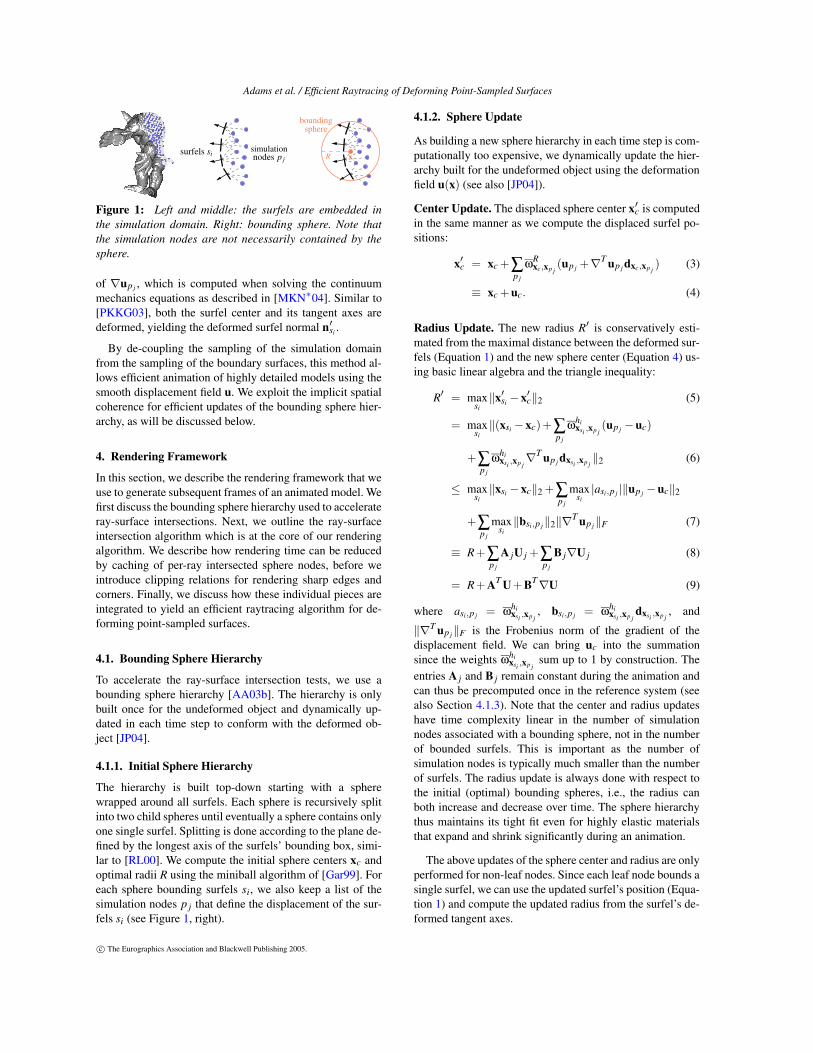
Our method for rendering deformable objects is based onthe animation framework of [MKN∗04] that allows physics-based simulation of elastically and plastically deformingsolids. To solve the equations of continuum mechanics, thesimulation volume is discretized with a set {p j} of simula-tion nodes (see Figure 1, left). The boundary surface of thesolid is represented by a (typically much larger) set {si} ofsurface elements (surfels). When deforming the material, thedisplacements of the surfels are determined from spatiallyadjacent simulation nodes using a free-form deformation ap-proach. In principle, however, our rendering algorithm canbe used with any animation method that applies the ideaof an embedded surface, e.g., mass-spring based systems orFEM-based approaches.
Initially, we assign to each surfel si a set of neighboringsimulation nodes p j (see Figure 1, middle). After an anima-tion step, the new position x′si of si is computed using a firstorder accurate approximation of the displacements up j of theneighboring simulation nodes p j as [MKN∗04]:
x′si = xsi +∑p j
ωhixsi ,xp j
(up j +∇T up j dxsi ,xp j), (1)
where dx,y = y − x, ωhx,y = ωh
x,y/∑y ωhx,y, and ωh
x,y is asmoothly decaying weight function with support radius h.We use the compactly supported radial spline function
ωhx,y = ω(r) =
{
1−6r2 +8r3 −3r4 r ≤ 10 r > 1,
(2)
where r = (‖x− y‖)/h. We reuse the MLS approximation
c© The Eurographics Association and Blackwell Publishing 2005.
Adams et al. / Efficient Raytracing of Deforming Point-Sampled Surfaces
simulation
boundingsphere
surfels si nodes p j xcR
Figure 1: Left and middle: the surfels are embedded inthe simulation domain. Right: bounding sphere. Note thatthe simulation nodes are not necessarily contained by thesphere.
of ∇up j , which is computed when solving the continuummechanics equations as described in [MKN∗04]. Similar to[PKKG03], both the surfel center and its tangent axes aredeformed, yielding the deformed surfel normal n′
si .
By de-coupling the sampling of the simulation domainfrom the sampling of the boundary surfaces, this method al-lows efficient animation of highly detailed models using thesmooth displacement field u. We exploit the implicit spatialcoherence for efficient updates of the bounding sphere hier-archy, as will be discussed below.
4. Rendering Framework
In this section, we describe the rendering framework that weuse to generate subsequent frames of an animated model. Wefirst discuss the bounding sphere hierarchy used to accelerateray-surface intersections. Next, we outline the ray-surfaceintersection algorithm which is at the core of our renderingalgorithm. We describe how rendering time can be reducedby caching of per-ray intersected sphere nodes, before weintroduce clipping relations for rendering sharp edges andcorners. Finally, we discuss how these individual pieces areintegrated to yield an efficient raytracing algorithm for de-forming point-sampled surfaces.
4.1. Bounding Sphere Hierarchy
To accelerate the ray-surface intersection tests, we use abounding sphere hierarchy [AA03b]. The hierarchy is onlybuilt once for the undeformed object and dynamically up-dated in each time step to conform with the deformed ob-ject [JP04].
4.1.1. Initial Sphere Hierarchy
The hierarchy is built top-down starting with a spherewrapped around all surfels. Each sphere is recursively splitinto two child spheres until eventually a sphere contains onlyone single surfel. Splitting is done according to the plane de-fined by the longest axis of the surfels’ bounding box, simi-lar to [RL00]. We compute the initial sphere centers xc andoptimal radii R using the miniball algorithm of [Gar99]. Foreach sphere bounding surfels si, we also keep a list of thesimulation nodes p j that define the displacement of the sur-fels si (see Figure 1, right).
4.1.2. Sphere Update
As building a new sphere hierarchy in each time step is com-putationally too expensive, we dynamically update the hier-archy built for the undeformed object using the deformationfield u(x) (see also [JP04]).
Center Update. The displaced sphere center x′c is computedin the same manner as we compute the displaced surfel po-sitions:
x′c = xc +∑p j
ωRxc,xp j
(up j +∇T up j dxc,xp j) (3)
≡ xc +uc. (4)
Radius Update. The new radius R′ is conservatively esti-mated from the maximal distance between the deformed sur-fels (Equation 1) and the new sphere center (Equation 4) us-ing basic linear algebra and the triangle inequality:
R′ = maxsi
‖x′si −x′c‖2 (5)
= maxsi
‖(xsi −xc)+∑p j
ωhixsi ,xp j
(up j −uc)
+∑p j
ωhixsi ,xp j
∇T up j dxsi ,xp j‖2 (6)
≤ maxsi
‖xsi −xc‖2 +∑p j
maxsi
|asi,p j |‖up j −uc‖2
+∑p j
maxsi
‖bsi,p j‖2‖∇T up j‖F (7)
≡ R+∑p j
A jU j +∑p j
B j∇U j (8)
= R+AT U+BT∇U (9)
where asi,p j = ωhixsi ,xp j
, bsi,p j = ωhixsi ,xp j
dxsi ,xp j, and
‖∇T up j‖F is the Frobenius norm of the gradient of thedisplacement field. We can bring uc into the summationsince the weights ωhi
xsi ,xp jsum up to 1 by construction. The
entries A j and B j remain constant during the animation andcan thus be precomputed once in the reference system (seealso Section 4.1.3). Note that the center and radius updateshave time complexity linear in the number of simulationnodes associated with a bounding sphere, not in the numberof bounded surfels. This is important as the number ofsimulation nodes is typically much smaller than the numberof surfels. The radius update is always done with respect tothe initial (optimal) bounding spheres, i.e., the radius canboth increase and decrease over time. The sphere hierarchythus maintains its tight fit even for highly elastic materialsthat expand and shrink significantly during an animation.
The above updates of the sphere center and radius are onlyperformed for non-leaf nodes. Since each leaf node bounds asingle surfel, we can use the updated surfel’s position (Equa-tion 1) and compute the updated radius from the surfel’s de-formed tangent axes.
c© The Eurographics Association and Blackwell Publishing 2005.
Adams et al. / Efficient Raytracing of Deforming Point-Sampled Surfaces
x x+ux′p j
up j
up j
R◦ txp j
Figure 2: Left: the displacements are computed relative tothe reference system. Right: the displacements are computedrelative to the optimally transformed reference system. Thisresults in smaller relative displacements.
4.1.3. Optimal Rigid Transformation
As illustrated in Figure 2, the displacements u of surfels andsimulation nodes are computed relative to the undeformedpositions x. The latter are defined in the reference system(material coordinates), while the displaced positions x′ arespecified in the deformed system (world coordinates). Al-though the bounding radius update of Equation 9 is invariantunder uniform translations (since then U j = 0 and ∇U j = 0),the sphere radii grow under uniform rotations.
We can address this problem by factoring out the optimalrigid transformation. After each iteration, we transform thereference system rigidly by computing the optimal global ro-tation and translation based on geometric algebra [LFDL98],similar to [TW88]. This will align the transformed referencesystem as closely as possible with the deformed system, re-sulting in smaller U j’s and ∇U j’s and thus in smaller boundsfor the updated sphere nodes (see Figure 2, right).
Translation. The optimal translation t = x′m −xm is the dif-ference between the centers of mass x′m = ∑p j
mp j x′p j andxm = ∑p j
mp j xp j of the displaced and the reference simula-tion nodes respectively, where mp j = mp j /∑p j
mp j , and mp j
is the mass of a simulation node p j .
Rotation. The optimal rotation R = VUT is computed in aleast squares sense by computing the singular value decom-position of F = UWVT , where
F = ∑p j
m2p j (xp j −xm)(x′p j −x′m)T . (10)
This linear transformation is applied to the reference po-sition of all simulation nodes, surfels and bounding spherecenters when used during raytracing. The quantities dx,y andωh
x,y remain constant under rigid transformations and there-fore the entries A j and B j of Equation 9 need to be computedonly once as discussed before.
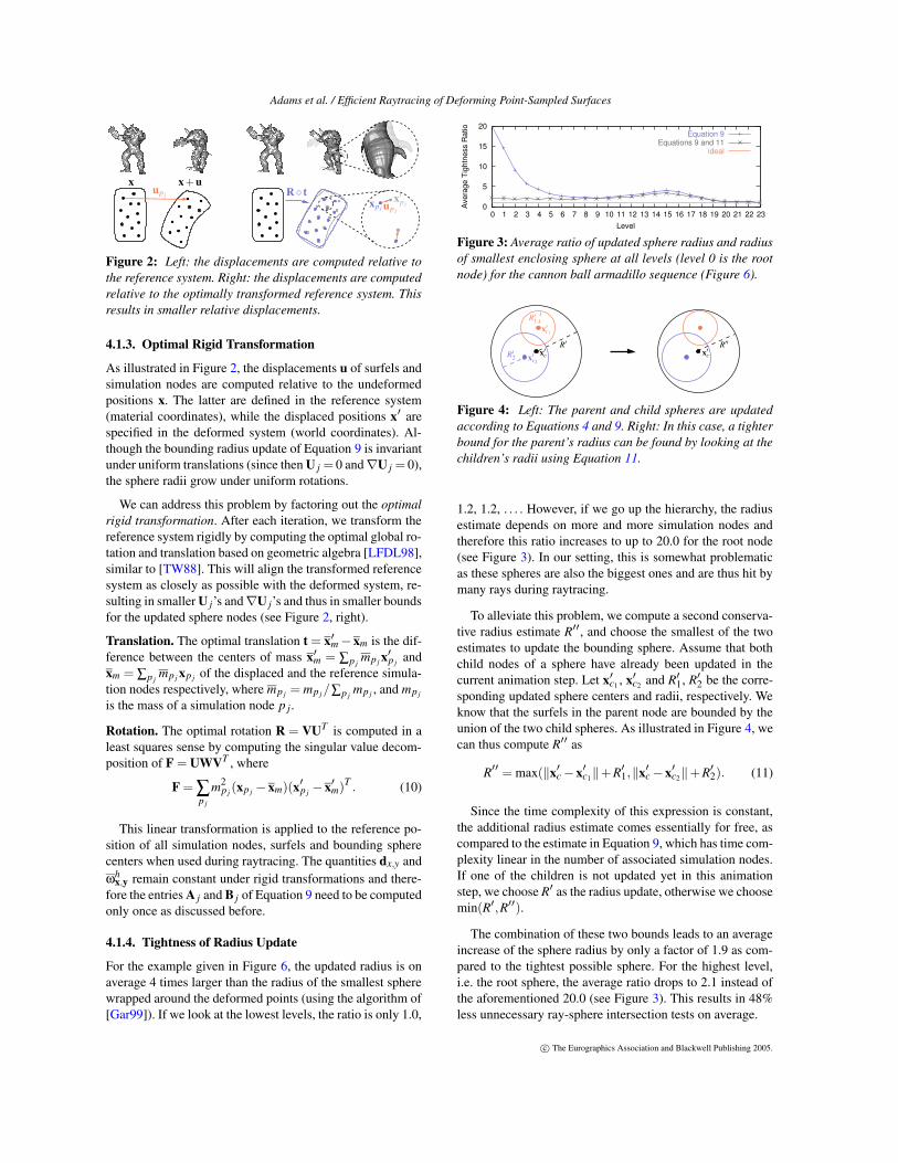
4.1.4. Tightness of Radius Update
For the example given in Figure 6, the updated radius is onaverage 4 times larger than the radius of the smallest spherewrapped around the deformed points (using the algorithm of[Gar99]). If we look at the lowest levels, the ratio is only 1.0,
0
5
10
15
20
0 1 2 3 4 5 6 7 8 9 10 11 12 13 14 15 16 17 18 19 20 21 22 23
Ave
rage
Tig
htne
ss R
atio
Level
Equation 9Equations 9 and 11
ideal
Figure 3: Average ratio of updated sphere radius and radiusof smallest enclosing sphere at all levels (level 0 is the rootnode) for the cannon ball armadillo sequence (Figure 6).
R′′
x′cx′cR′
R′1
x′c1
R′2 x′c2
Figure 4: Left: The parent and child spheres are updatedaccording to Equations 4 and 9. Right: In this case, a tighterbound for the parent’s radius can be found by looking at thechildren’s radii using Equation 11.
1.2, 1.2, . . . . However, if we go up the hierarchy, the radiusestimate depends on more and more simulation nodes andtherefore this ratio increases to up to 20.0 for the root node(see Figure 3). In our setting, this is somewhat problematicas these spheres are also the biggest ones and are thus hit bymany rays during raytracing.
To alleviate this problem, we compute a second conserva-tive radius estimate R′′, and choose the smallest of the twoestimates to update the bounding sphere. Assume that bothchild nodes of a sphere have already been updated in thecurrent animation step. Let x′c1 , x′c2 and R′
1, R′
2 be the corre-sponding updated sphere centers and radii, respectively. Weknow that the surfels in the parent node are bounded by theunion of the two child spheres. As illustrated in Figure 4, wecan thus compute R′′ as
R′′ = max(‖x′c −x′c1‖+R′
1,‖x′c −x′c2‖+R′
2). (11)
Since the time complexity of this expression is constant,the additional radius estimate comes essentially for free, ascompared to the estimate in Equation 9, which has time com-plexity linear in the number of associated simulation nodes.If one of the children is not updated yet in this animationstep, we choose R′ as the radius update, otherwise we choosemin(R′,R′′).
The combination of these two bounds leads to an averageincrease of the sphere radius by only a factor of 1.9 as com-pared to the tightest possible sphere. For the highest level,i.e. the root sphere, the average ratio drops to 2.1 instead ofthe aforementioned 20.0 (see Figure 3). This results in 48%less unnecessary ray-sphere intersection tests on average.
c© The Eurographics Association and Blackwell Publishing 2005.

Adams et al. / Efficient Raytracing of Deforming Point-Sampled Surfaces
4.2. Ray-Surface Intersections
We start by briefly describing the ray-surface intersection al-gorithm for point-sampled surfaces. Next, we demonstratehow we exploit temporal coherence to increase the perfor-mance of intersection tests.
4.2.1. Intersection Algorithm
When a ray hits a leaf node, we intersect it with the el-lipse defined by the node’s surfel. This intersection point xserves as an initial guess for the following iterative proce-dure [AA04]:
• Compute the weighted average a(x) of the deformed sur-fel positions and the weighted average n(x) of surfel nor-mals in the neighborhood of x within a distance h:
a(x) =∑si
ωhx,x′si
x′si
∑siωh
x,x′si
, n(x) =∑si
ωhx,x′si
n′
si
‖∑siωh
x,x′sin′
si‖. (12)
These define a plane f (x) = n(x)T (x−a(x)) = 0.• Test for convergence. The iterative intersection algorithm
has converged if | f (x)|< ε. If not converged, intersect theray with this plane. This yields a new intersection point x′.If x′ falls outside the node’s bounding sphere, the iterationis stopped and the intersection point is rejected.
• Repeat the above steps until convergence.
As shown in [AA03a] this procedure quickly convergesdepending on the initial guess. In our examples we need 3iterations on average before convergence.
We avoid expensive nearest neighbor queries by usinga static surfel neighborhood for the leaf nodes. The sur-fel neighbors are precomputed in the undeformed system.Whenever a ray hits a leaf node we use the stored surfels sias neighbors for the initial intersection point. Note that theweights ωh
x,x′siare computed against the current intersection
point, not against the center of the leaf node. For the exam-ples given in this paper we used fixed neighborhoods of 16surfels.
4.2.2. Sphere Node Caching
We can reduce the number of ray-sphere intersection testsby caching intersected sphere nodes from frame to frame.For each ray we store the sphere node where we found theclosest intersection point (i.e. the one with the smallest t-value). In the next frame, we first test for intersection usingthis cached sphere node (if there is any). In many cases thisgives us a good upper bound for the intersection depth of theray. Next, we test against the root node and descend the hi-erarchy as usual. However, thanks to the upper bound of theintersection depth, many more spheres are trivially culledresulting in less sphere updates and less ray-surface inter-section tests. We experienced a decrease of 27% on averagein the number of performed intersection tests thanks to thesphere node caching.
4.3. Clipping
To be able to render sharp edges and corners we have in-corporated a new clipping technique. Surfels are grouped insurfel collections between which we explicitly store clippingrelations. Suppose we have a sharp edge defined as the in-tersection of two surfaces S1 and S2. Whenever a ray inter-sects a surfel of surface S1 we test if the intersection point isclipped by surface S2. If so, the intersection is rejected.
To be able to perform the clipping test, we store for eachsurfel of S1 the two nearest surfels of S2 and vice versa(these are precomputed and cached for the undeformed sur-faces). Clipping is performed using these two nearest sur-fels of the other surface using the technique proposed in[WTG04]. Note that clipping is done in (deformed) objectspace, as opposed to [WTG04] where clipping is performedin image space. This has the advantage that we are able toanti-alias the sharp edges and corners by super-sampling (seeFigure 8).
4.4. Putting It All Together
In this section we describe how the individual pieces de-scribed above are combined to yield the final rendering al-gorithm for deformable models.
Precomputation. For each surfel si compute its surfelneighbors. If there are clipping relations, precompute theclipping neighbors for the relevant surfels. Also compute thesimulation nodes p j and the corresponding weights ωhi
xsi ,xp j
that define the displacement of si. Build the initial bound-ing sphere hierarchy for the undeformed object. For eachsphere keep a list of simulation nodes p j used by the surfelsbounded by the sphere and keep the corresponding weightsωR
xc,xp j. Precompute the entries in A and B for each sphere
(Equation 9).
Rendering. For each ray, test for intersection against thecached sphere node before testing against the whole hier-archy. When a node is visited for the first time, update thecenter and the radius using Equations 4 and 9. If a node isalready visited before, update the radius using Equation 11,if possible. When eventually the ray hits a leaf node, up-date the surfel si corresponding to this node and its surfelneighbors using Equation 1 (if not already done before inthis time step). For leaf nodes we use the center of the as-sociated surfel as the center of the sphere. Intersect the raywith the ellipse defined by si. Perform the iterative intersec-tion algorithm. If necessary, check whether the intersectionpoint is rejected by one or more clipping surfaces.
Note that both the update of the sphere nodes and the up-date of the surfels are done in a lazy manner. Only the nodesand surfels visited in this time step are updated, leading toadditional savings in computation time.
Optimization For Shadow Rays. When traversing the hi-erarchy for shadow rays, we can reduce the number of ad-
c© The Eurographics Association and Blackwell Publishing 2005.

Adams et al. / Efficient Raytracing of Deforming Point-Sampled Surfaces
Model #Surfels #Sim. Nodes #Spheres #Levels
Armadillo 170k 453 346k 23Goblin 100k 502 200k 24
CSG Head 91k 253 182k 23Elastic Ball 6k 88 10k 14
Table 1: Sampling statistics for the different models used inour examples.
ditional spheres to be updated. If a shadow ray intersects aparent sphere of which only one child is already updated, wefirst test the ray against the updated child. As for shadow raysany intersection point counts (i.e. we do not have to searchfor the closest one), most of the time the other child branchdoes not have to be updated nor traversed.
5. Results
We have tested our implementation using four animation se-quences, all rendered at a resolution of 512 by 384 pixels.The sampling statistics are given in Table 1, average ren-dering times (averaged over 3 runs on a Pentium 4, 3GHz,512Mb ram) are indicated in Figure 5.
The first animation shows the armadillo being hit by acannon ball (Figure 6). As can be seen on the left plot inFigure 5, we achieve an average speedup of a factor 2.1 (8.5seconds per frame compared to 18.5 seconds per frame onaverage) compared to the naive technique, where the spherehierarchy is rebuilt in each time step. In the beginning andend of the animation we clearly gain from caching spherenodes as the object does not deform significantly. In the mid-dle of the animation we also gain from the fact that a largepart of the armadillo is occluded by the cannon ball. Thisresults in less sphere node and surface updates.
The second sequence shows a goblin creature practicinggymnastics on the parallel bars (Figure 7). Timing statisticsare given on the second graph in Figure 5. Again, we obtaina speedup of a factor 2.1 (6 seconds per frame compared to12.8 seconds per frame on average). In this sequence we gainfrom the fact that large parts of the goblin are self-occludedand do not have to be updated from frame to frame. Notethat the middle curve touches the upper curve around frame160. Here the goblin is deformed the most, resulting in theworst fit of the bounding sphere hierarchy.
The third sequence shows three bouncing heads (Fig-ure 8). Each head consists of three surfaces between whichexplicit clipping relations are defined (see Section 4.3). Thetimings on Figure 5 indicate a speedup of a factor 2.2 (19seconds per frame compared to 42.8 seconds per frame onaverage).
Finally, the last animation shows 40 elastic balls beingthrown inside a hollow cube (see Figure 9). Thanks to thedynamic sphere updates and the sphere node caching we ob-tain an average speedup of a factor 3 compared to the naive
technique (15 seconds per frame compared to 45 seconds perframe on average).
6. Discussion and Future Work
As demonstrated in Figure 5, exploiting spatial and tempo-ral coherence leads to significant performance gains over thenaive approach. Speedups are particularly high if the num-ber of surfels is large compared to the number of simulationnodes, since sphere updates are linear in the number of simu-lation nodes. Our method also performs well for animationswhere large parts of the surface are occluded and thus nottouched by any rays (e.g. for the animation of Figure 9).
Situations may arise however where refitting (parts of) thesphere hierarchy is more efficient than lazy updating. As lazyupdating results in sub-optimal bounding spheres, it also re-sults in more ray sphere intersection testing compared tothe optimal sphere hierarchy. Our experiments showed thatthe break-even point (speedup of 1) varies significantly withthe specific sequence. Therefore, one might want to deviseheuristics to decide whether to use lazy updating or to per-form a (full) sphere hierarchy update.
Storing and reusing spatial and temporal proximity infor-mation naturally leads to increased memory consumption.The main bottlenecks are the sphere nodes: for each nodewe keep a list of simulation nodes and the correspondingweights ωR
xc,xp j, and entries A j and B j (see Equation 9).
However, for the armadillo sequence, where all the surfelshave 16 simulation node neighbors, the sphere nodes haveto store only 16.4 simulation nodes on average, since childnodes share their simulation nodes with the associated sur-fels. Storing static surfel neighborhoods requires an addi-tional 16 pointers per surfel. For the caching of per-ray inter-sected sphere nodes we can trade off cache size with cachehit rate by setting a maximum cache size.
Memory overhead can be significantly reduced whenmany instances of the same model are present in a scene(e.g. the animations of Figures 8 and 9). In such cases, wecan reuse the same (undeformed) sphere node hierarchy,even if the individual instances deform differently. Sincethe weights ωR
xc,xp j, entries A j and B j , and neighborhood
relations are constant over all instances, we only need tostore the properties of the deformed simulation nodes, spherenodes, and surfels for each instance.
Tighter bounds on the radius update could be obtainedusing a hierarchical approach when computing the optimalrigid transformation (see Section 4.1.3). Instead of com-puting a single transformation for the whole object, onecould segment the simulation nodes in different sets andcompute an optimal transformation for each set similar to[MHTG05]. For example, the model of Figure 7 could besplit into two sets, one for the body and one for the hands.This yields smaller simulation node displacements and thussmaller bounds for the updated radii.
c© The Eurographics Association and Blackwell Publishing 2005.
Adams et al. / Efficient Raytracing of Deforming Point-Sampled Surfaces
Currently, our method is only suitable for animated mod-els with fixed topology. For highly dynamic substances, suchas fracturing solids or fluids, our caching schemes would failsince neighborhood relations change too frequently. How-ever, we plan to extend our method with dynamic up- anddown-sampling of surfels and simulation nodes to betterhandle models that experience extreme deformations. As re-sampling is often a very localized operation, we expect thatupdating of cached neighbors will be fairly efficient.
We want to stress that even though our method is imple-mented in the context of a point-based animation framework,our dynamic sphere hierarchy can also be used for other sur-face representations. For example, if the boundary surface ofthe solid is given as a polygonal mesh embedded in an FEMsimulation grid [MG04], the same algorithms can be used byapplying the deformation field to the mesh vertices.
7. Conclusion
We have introduced a new method for efficient raytracing ofanimated point-sampled surfaces. Central to our method is adynamic bounding sphere hierarchy that is used to accelerateray-surface intersection tests. By de-coupling the samplingof the simulation domain from the sampling of the boundarysurfaces, we are able to update the hierarchy by only look-ing at the deformation of the simulation nodes. Moreover,the update is done in a lazy manner, only touching spheresand surfels that are actually used during rendering. We showhow this dynamic update and additional caching of inter-sected sphere nodes lead to an efficient raytracing algorithmobtaining speedups of over a factor of 2 compared to exist-ing techniques. Finally, our method incorporates the render-ing of sharp edges and corners which are explicitly definedusing surface clipping relations.
Acknowledgements. The authors wish to acknowledge supportfrom NSF grants CARGO-0138456, ITR-0205671, ARO grantDAAD19-03-1-033, and NIH Simbios Center grant 1091129-1-PABAE. Bart Adams is funded as a Research Assistant by the Fundfor Scientific Research - Flanders, Belgium (F.W.O.-Vlaanderen).
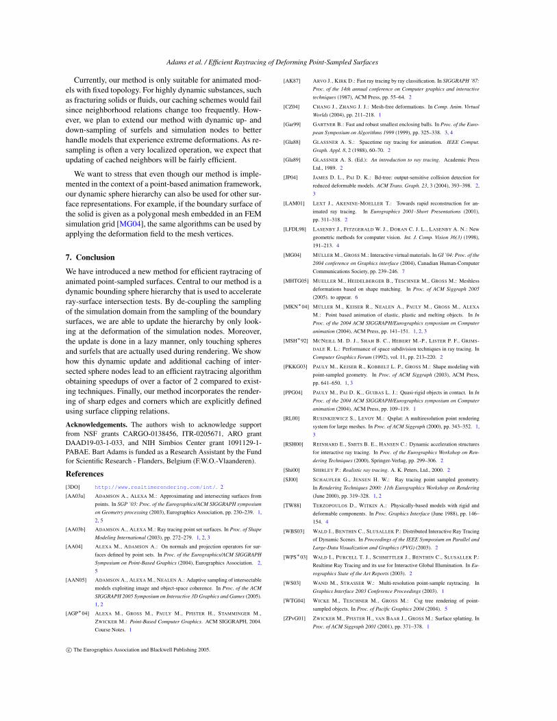
References[3DO] http://www.realtimerendering.com/int/. 2
[AA03a] ADAMSON A., ALEXA M.: Approximating and intersecting surfaces frompoints. In SGP ’03: Proc. of the Eurographics/ACM SIGGRAPH symposium
on Geometry processing (2003), Eurographics Association, pp. 230–239. 1,2, 5
[AA03b] ADAMSON A., ALEXA M.: Ray tracing point set surfaces. In Proc. of Shape
Modeling International (2003), pp. 272–279. 1, 2, 3
[AA04] ALEXA M., ADAMSON A.: On normals and projection operators for sur-faces defined by point sets. In Proc. of the Eurographics/ACM SIGGRAPH
Symposium on Point-Based Graphics (2004), Eurographics Association. 2,5
[AAN05] ADAMSON A., ALEXA M., NEALEN A.: Adaptive sampling of intersectablemodels exploiting image and object-space coherence. In Proc. of the ACM
SIGGRAPH 2005 Symposium on Interactive 3D Graphics and Games (2005).1, 2
[AGP∗04] ALEXA M., GROSS M., PAULY M., PFISTER H., STAMMINGER M.,ZWICKER M.: Point-Based Computer Graphics. ACM SIGGRAPH, 2004.Course Notes. 1
[AK87] ARVO J., KIRK D.: Fast ray tracing by ray classification. In SIGGRAPH ’87:
Proc. of the 14th annual conference on Computer graphics and interactive
techniques (1987), ACM Press, pp. 55–64. 2
[CZ04] CHANG J., ZHANG J. J.: Mesh-free deformations. In Comp. Anim. Virtual
Worlds (2004), pp. 211–218. 1
[Gar99] GARTNER B.: Fast and robust smallest enclosing balls. In Proc. of the Euro-
pean Symposium on Algorithms 1999 (1999), pp. 325–338. 3, 4
[Gla88] GLASSNER A. S.: Spacetime ray tracing for animation. IEEE Comput.
Graph. Appl. 8, 2 (1988), 60–70. 2
[Gla89] GLASSNER A. S. (Ed.): An introduction to ray tracing. Academic PressLtd., 1989. 2
[JP04] JAMES D. L., PAI D. K.: Bd-tree: output-sensitive collision detection forreduced deformable models. ACM Trans. Graph. 23, 3 (2004), 393–398. 2,3
[LAM01] LEXT J., AKENINE-MOELLER T.: Towards rapid reconstruction for an-imated ray tracing. In Eurographics 2001–Short Presentations (2001),pp. 311–318. 2
[LFDL98] LASENBY J., FITZGERALD W. J., DORAN C. J. L., LASENBY A. N.: Newgeometric methods for computer vision. Int. J. Comp. Vision 36(3) (1998),191–213. 4
[MG04] MÜLLER M., GROSS M.: Interactive virtual materials. In GI ’04: Proc. of the
2004 conference on Graphics interface (2004), Canadian Human-ComputerCommunications Society, pp. 239–246. 7
[MHTG05] MUELLER M., HEIDELBERGER B., TESCHNER M., GROSS M.: Meshlessdeformations based on shape matching. In Proc. of ACM Siggraph 2005
(2005). to appear. 6
[MKN∗04] MÜLLER M., KEISER R., NEALEN A., PAULY M., GROSS M., ALEXA
M.: Point based animation of elastic, plastic and melting objects. In In
Proc. of the 2004 ACM SIGGRAPH/Eurographics symposium on Computer
animation (2004), ACM Press, pp. 141–151. 1, 2, 3
[MSH∗92] MCNEILL M. D. J., SHAH B. C., HEBERT M.-P., LISTER P. F., GRIMS-DALE R. L.: Performance of space subdivision techniques in ray tracing. InComputer Graphics Forum (1992), vol. 11, pp. 213–220. 2
[PKKG03] PAULY M., KEISER R., KOBBELT L. P., GROSS M.: Shape modeling withpoint-sampled geometry. In Proc. of ACM Siggraph (2003), ACM Press,pp. 641–650. 1, 3
[PPG04] PAULY M., PAI D. K., GUIBAS L. J.: Quasi-rigid objects in contact. In In
Proc. of the 2004 ACM SIGGRAPH/Eurographics symposium on Computer
animation (2004), ACM Press, pp. 109–119. 1
[RL00] RUSINKIEWICZ S., LEVOY M.: Qsplat: A multiresolution point renderingsystem for large meshes. In Proc. of ACM Siggraph (2000), pp. 343–352. 1,3
[RSH00] REINHARD E., SMITS B. E., HANSEN C.: Dynamic acceleration structuresfor interactive ray tracing. In Proc. of the Eurographics Workshop on Ren-
dering Techniques (2000), Springer-Verlag, pp. 299–306. 2
[Shi00] SHIRLEY P.: Realistic ray tracing. A. K. Peters, Ltd., 2000. 2
[SJ00] SCHAUFLER G., JENSEN H. W.: Ray tracing point sampled geometry.In Rendering Techniques 2000: 11th Eurographics Workshop on Rendering
(June 2000), pp. 319–328. 1, 2
[TW88] TERZOPOULOS D., WITKIN A.: Physically-based models with rigid anddeformable components. In Proc. Graphics Interface (June 1988), pp. 146–154. 4
[WBS03] WALD I., BENTHIN C., SLUSALLEK P.: Distributed Interactive Ray Tracingof Dynamic Scenes. In Proceedings of the IEEE Symposium on Parallel and
Large-Data Visualization and Graphics (PVG) (2003). 2
[WPS∗03] WALD I., PURCELL T. J., SCHMITTLER J., BENTHIN C., SLUSALLEK P.:Realtime Ray Tracing and its use for Interactive Global Illumination. In Eu-
rographics State of the Art Reports (2003). 2
[WS03] WAND M., STRASSER W.: Multi-resolution point-sample raytracing. InGraphics Interface 2003 Conference Proceedings (2003). 1
[WTG04] WICKE M., TESCHNER M., GROSS M.: Csg tree rendering of point-sampled objects. In Proc. of Pacific Graphics 2004 (2004). 5
[ZPvG01] ZWICKER M., PFISTER H., VAN BAAR J., GROSS M.: Surface splatting. InProc. of ACM Siggraph 2001 (2001), pp. 371–378. 1
c© The Eurographics Association and Blackwell Publishing 2005.

Adams et al. / Efficient Raytracing of Deforming Point-Sampled Surfaces
0.0
10.0
30.0
40.0
50.0
60.0
70.0
2 100 200 300
Tim
e (s
ec)
Frame
15.021.5
45.0
No coherenceOur method (without caching)
Our method (with caching)0.0
10.0
20.0
30.0
40.0
50.0
2 50 100 150 200
Tim
e (s
ec)
Frame
26.2
42.8
No coherenceOur method (without caching)
Our method (with caching)0.0
2.0
4.0
6.0
8.0
10.0
12.0
14.0
16.0
2 100 200 300 400
Tim
e (s
ec)
Frame
12.8
No coherenceOur method (without caching)
Our method (with caching)0.0
5.0
10.0
15.0
20.0
25.0
2 100 200 300 400 500
Tim
e (s
ec)
Frame
8.5
12.0
18.5
No coherenceOur method (without caching)
Our method (with caching)
Elastic BallsBouncing HeadsGymnastic GoblinCannon Ball Armadillo
Figure 5: Timing statistics for the different sequences. From left to right: cannon ball armadillo sequence, gymnastic goblinsequence, bouncing heads sequence and elastic balls sequence. The straight lines represent the average rendering time overall frames. The upper curve is the timing without considering any coherence. The middle curve is timed using our techniquewithout sphere node caching enabled. The lower curve shows the average time per frame employing all acceleration techniquespresented in this paper.
Figure 6: Four frames of the cannon ball armadillo sequence.
Figure 7: Four frames of the gymnastic goblin sequence.
Figure 8: Four frames of the bouncing heads sequence.
Figure 9: Four frames of the elastic balls sequence.
c© The Eurographics Association and Blackwell Publishing 2005.