education - creative building toys for kids | k’nex | www...
TRANSCRIPT

Education®
TEACHER’SGUIDE
LEVERS AND PULLEYS
UNDERSTANDING MECHANISMS
78610

1
Understanding�Mechanisms:Levers�and�Pulleys�Teacher’s�Guide
96562-V3-10/14© 2014 K’NEX Limited Partnership Group and its licensors.
Text: Dr. Alex Wright,AW Education, Wrexham, LL12 7LR, U.K.
K’NEX Limited Partnership GroupP.O. Box 700Hatfield, PA 19440-0700
Visit our website at www.knexeducation.co.ukor www.knexeducation.com
Email: [email protected]
K’NEX Education is a Registered Trademark of K’NEX Limited Partnership Group.
Conforms to the Requirements of ASTM Standard Consumer Safety Specification on Toy Safety, F963-03.Manufactured under U.S. Patents 5,061,219; 5,199,919; 5,350,331; 5,137,486. Other U.S. and foreign patents pending.
Protected by International Copyright. All rights reserved.
Und
erstanding M
echanisms
Education®
levers and pulleys
website: www.knexeducation.co.uk
WARNING:CHOKING HAZARD - Small parts.Not for children under 3 years.
A Note About SafetySafety is of primary concern in science and technology classrooms. It is recommended that you develop a set of rules that governs the safe, proper use of K’NEX in your classroom. Safety, as it relates to the use of the elastic bands should be specifically addressed.
PARTICULAR CAUTIONS:Children should not overstretch or overwind their elastic bands. Over- stretching and overwinding can
cause the elastic band to snap and cause personal injury. Any wear and tear or deterioration of elastic bands should be reported immediately to the teacher. Teachers and children should inspect elastic bands for deteriora-tion before each experiment.
Caution children to keep hands and hair away from all moving parts. Never put fingers in moving gears or other moving parts.

2

3
IntroductionYour K’NEX Levers and Pulleys kit is part of a series called “Understanding Mechanisms”. The series has been produced to enable Key Stage 2 pupils to investigate and evaluate some familiar products, to think about how they work and to explore the mechanisms that make them work.
Understanding Mechanisms: Levers and Pulleys Kit
• Developedtointroducepupilstothe way levers and pulleys have been used in the design of familiar products, this construction kit also serves to make the connection between the models the pupils have built and the science that makes them work.
• Workinginpairsorsmallcollaborative groups, the kit provides opportunities for pupils to explore lifting mechanisms through the use of investigative, disassembling and evaluative activities (IDEAs) and focused practical tasks (FPTs).
Teacher Support Materials
• Developedinitiallyforthenon-specialist teacher, the materials included in the Teacher’s Guide can also be used as a resource by more experienced teachers as they develop their own lesson plans.
• Implementingtheideasandinformation included in the Teacher’s Guide can build your pupils’ knowledge and understanding of mechanisms, and the ways in which they can be used to make things move.
• Keybackgroundinformationisprovided in “A Quick Guide”, while the Lesson Notes for each K’NEX model provide more detailed information and ideas for possible teaching activities. These teaching activities have been developed primarily to support the DfEE/QCA Scheme of Work for Key Stages 1 and 2 in Design and Technology and Science, the DATA Design and Technology Primary Lesson Plans and Primary Helpsheets.
• Aglossaryoftechnicaltermsand scientific definitions is offered as a resource for the teacher.
• Eachofthelessonscanbecompleted in one hour but may be extended using the suggested Extension and Research Activities. Useful Internet web sites are listed to help guide the research activities. (Note: these were functioning sites at the time of going to print.)
• Theteachingactivitiesarealsointended to encourage the development of key skills by providing opportunities for whole class and group discussions, observing, evaluating and recording through the use of text and drawings, working with others to solve problems and using ICT within a design and technology context.
TABLE OF CONTENTSLevers 4-38
A Quick Guide to Levers 4-10 Lesson 1: Getting Started 11-12 Lesson 2.1 and 2.2: The Seesaw 13-19 Lesson 3: The Balance 20-25 Lesson 4: The Wheelbarrow 26-29 Lesson 5: The Ice Hockey Stick 30-34 Lesson 6: The Scissors 35-38
Pulleys 39-61
A Quick Guide to Pulleys 39-42 Lesson 7: The Flagpole 43-47 Lesson 8: The Sailboat 48-51 Lesson 9: The Block and Tackle 52-56
Key Terms and Scientific Definitions 57-61
Und
erstanding M
echanisms
Education®
levers and pulleys
website: www.knexeducation.co.uk

4
A�Quick�Guide�to�Levers
5C: ‘Moving Toys’ and 6C: ‘Fairground’: and in Science Units 1E: ‘Pushes and Pulls’; 2E: ‘Force and Movement’; 6E: ‘Balanced and Unbalanced Forces’.
In addition, working with levers helps children relate science to the ways familiar machines work.
What is a lever?A lever is a rigid beam, bar or rod that is able to turn or rotate about a fixed point called the fulcrum. For example:
In the curriculum, the concept of levers may be used in designing and making activities associated with the QCA/DfEE Exemplar Scheme of Work for Design and Technology Units 1A: ‘Playgrounds’; 1D: ‘Moving Pictures’; 3C: ‘Moving Monsters’; 4B: ‘Storybooks’;
The key parts of a lever are:
• Fulcrum - a fixed point that allows the beam to rotate around it and can occur at any point along the lever. It can be in the centre, as in a seesaw and a simple balance; off centre, as in a beam balance and claw hammer; or at one end, as in the hinge on a door, nutcrackers and tweezers.
It is thought that levers have been in use since prehistoric times. They were most likely used to help people lift and move heavy rocks in the Palaeolithic era, to build megalithic structures such as Stonehenge in the Neolithic period, and were the basis of the balances used by early traders and merchants to weigh gold and other valuable trade goods. Today they are found in many commonly used devices such as scissors, pliers, stapling machines, tweezers, and nutcrackers. Even cricket bats, hockey sticks, tennis racquets and JCB™ excavating machines use the principle of levers to make them work.
Fig. 1
Education®

5
A Q
uick Guid
e to Levers
• Effort - the force you apply to the lever to move an object or to overcome a resistance. The effort can be a push, pull, squeeze or lift.
• Load - the mass of the object you need to move or the resistance to movement that must be overcome by the lever. This object provides the force that acts against the effort. For example, the weight of a heavy object to be moved, or a piece of paper that is resisting the cutting action of the scissor blades, or friction preventing a nail from being pulled out of a piece of wood. In fact, the load can be anything that provides a resistance to your effort.
What can levers do for us?Levers can…
• Makejobseasierforustodo. Lifting or moving a heavy object requires a large amount of effort. A lever can make it easier to move the object by reducing the amount of effort force needed to do the job. It does this by amplifying the forces where they are needed. Consider how you would pull a nail out of a piece of wood without using a claw hammer, open a soft drink bottle without a bottle opener, or move a load of sand without a wheelbarrow. A clawhammer, bottle opener and wheelbarrow are each examples of a lever in action. In each case they help by reducing the effort that is needed to perform a specific task.
The longer the lever, the greater the amplification of the effort forces used and the easier it is to carry out the job. Archimedes is supposed to have said, “Give me a lever long enough and I can move the Earth”.
• Changethedirectionof the applied force. A push down on one side of a seesaw, for example, results in the opposite side moving upwards.
• Amplifyordecreasetheamountof output movement. For example, a small movement at the effort end of a car park barrier produces a large movement at the load end.
A push up here…
…makes this side move down
Education®
levers and pulleys
website: www.knexeducation.co.uk

6
A�Quick�Guide�to�Levers
• Increasethespeedtheloadmoves. This characteristic of a lever can be seen in the seige engines known as trebuchets that were used to throw large stones at castle walls in medieval times.
Figure 2 shows a large medieval trebuchet - a giant lever in which the fulcrum is off-centre. A massive effort is applied to move a small load. The end of the long arm on the load side is made to move very quickly, accelerating the sling holding the load and propelling it forward over a long distance. Trebuchets caused enormous damage because they were able to toss objects at castle walls at speeds in excess of 160 kilometres an hour. Fishing rods and hockey sticks use the same principle.
Visit http://www.flyingpig.co.uk/Pages/lever2.htm to see a trebuchet in action.
Visit http://wwwpbs.org/wbgh/nova/lostempires/trebuchet/builds.html to see photos of the reconstruction of a trebuchet.
Are all levers the same?There are three basic types of lever: 1st Class, 2nd Class and 3rd Class levers. They all share the common components of a rigid rod or beam, fulcrum, effort and load. They differ only in the relative positions of the fulcrum, effort and load.
1st Class Levers
Key facts
• In a 1st Class lever the fulcrum is positioned between the effort and the load.
• Theeffortandloadmoveinopposite directions. 1st Class levers, therefore, can be used to change the direction of an applied force. For example a downward push on one end of the lever can result in an upward push or pull at the other end.
• Theeffortforcecanbeamplifiedby increasing the length of the effort arm. The longer the effort arm, the easier it is to move the load.
• Thelongertheloadorresistancearm,the faster the load can be made to move. For example: the trebuchet.
Fig. 2
Fig. 3
Education®

7
A Q
uick Guid
e to Levers
The Principle of Levers identifies a relationship between the effort, the load and the distance of each from the fulcrum. This principle states that a lever is balanced (or in a state of equilibrium) when:
Key factsIn a 2nd Class lever:
• The load is between the effort and the fulcrum.
• The effort and load move in the same direction.
the effort x its distance from the fulcrum on one side
the load x its distance from the fulcrum on the opposite side =
A pair of scissors is an example of two 1st Class levers working together. Squeezing the handles together produces the effort, the hinge is the fulcrum and the resistance of the card being cut is the load. The strongest cutting action is nearest the hinge.
Wire cutters have longer arms than scissors. This design modification generates a much more powerful cutting action by increasing the length of the effort arm.
Fig. 4
2nd Class Levers
Education®
levers and pulleys
website: www.knexeducation.co.uk

8
A�Quick�Guide�to�Levers
3rd Class Levers
Compound 2nd Class levers.
Fig. 5
Nutcrackers are made from two 2nd Class levers. The effort is applied to the effort arms when a hand squeezes them together, the load is the resistance of the nut’s shell to cracking and the fulcrum is the hinge.
Key factsIn a 3rd Class lever:
• The effort is between the fulcrum and the load.
• Theeffortandloadmoveinthe same direction.
• 3rdClassleversalwaysincreasethe speed the load moves because the effort is always positioned closer to the fulcrum than the load. (See Fig. 5). Applying the effort close to the fulcrum requires a large input force but the effort arm only moves through a small distance. The opposite end of the lever (or load arm), however, moves through a greater distance, at a faster speed, but with less force.
In Fig. 6 the load is located twice as far from the fulcrum as the effort. In this example the load moves twice as fast as the effort, because it must move double the distance in the same amount of time.
That’s the trade off. In order to get greater speed, a large effort force is needed to move a small load.
Fig. 6
• 2nd Class levers always amplify the output force. In this type of lever arrangement, the load is always closer to the fulcrum than the effort force. This means the effort arm will be longer than the load arm (see diagram). The longer the effort arm, the more the effort force is amplified where it is needed, so making it easier to move the load. With a 2nd Class lever, therefore, it is possible to move a large load with a smaller effort.
Education®

9
• 3rdClassleversarenotasefficientas other levers because the load is always further from the fulcrum than the effort.
A Q
uick Guid
e to Levers
Compound 3rd Class levers
A small movement of the fingers squeezing the two arms together produces a long movement at the tips of the tweezers in order to grip an object such as a hair. The load is the resistance of the hair.
For example, raising a fish with a fishing rod actually requires more effort force than just lifting the fish using only a hand- held line. A fishing rod, however, helps by lifting the fish quickly. A small movement of your hands near the fulcrum produces a large movement at the tip of the rod, but both move in the same period of time. As a result, the tip of the rod (and the fish attached to it) actually moves more quickly than the hands and this quick action can help land the fish before it escapes.
Some machines use more than one type of lever in their working mechanisms.
Nail clippers involve a double action - the handle presses down onto the tweezer-like action of the cutters. The handle is a 2nd Class lever while the cutter is a 3rd Class lever.
The head of the claw hammer is a 3rd Class lever while the claw is a 1st class lever.
Education®
levers and pulleys
website: www.knexeducation.co.uk

10
A�Quick�Guide�to�Levers
Useful Web Sites.
http://www.enchantedlearning.com/physics/ machines/Levers.shtml This web site has some very simple animated drawings of the different types of levers in action.
http://www.coe.uh.edu/archiveThe University of Houston archive of lessons. Go to: Collection > Science > Lesson plans > Simple Machines.
www.flying-pig.co.uk A general site for simple machines offering useful animated drawings of mechanisms in action.
www.howstuffworks.com A library of information on different types of machines. Useful background information for teachers – you will need to use the search facility to find information.
www.mos.org/sln/Leonardo/ InventorsToolbox.html A useful site covering general information on levers and other simple machines.
www.smartown.com/sp2000/machines2000/ Simple machines made simpler. A good introduction to simple machines made by school children.
The main boom is a3rd class lever.
The excavating arm is a 1st class lever.
Fulcrum
Load
Effort
The excavating arm is hinged onto the main boom and is pulled and pushed by the hydraulic cylinder attached to the main boom. The arm and bucket operating mechanism are examples of 1st class levers in action.
Fulcrum
LoadEffort
The main boom and excavator arm together make up a 3rd class lever. The effort force is the push and pull provided by the hydraulic cylinder between the digger chassis and the moving arm.
JCB excavators that use a series of hydraulically operated arms are good examples of multiple levers in action.
Education®

Lesson�1:�Getting�StartedLesson 1: G
etting Started
Time: 1 hour
LearningObjectives - Children should learn: •toassemble,joinandcombinematerialsandcomponents
•thatconstructionmaterialcanbeusedtotryoutideas
•torecogniseshapesandtheirapplicationinstructures
•todrawandlabeldesigns
Vocabularydimensional, 2D, 3D, cubes, cuboids, cylinders, symmetrical, Rods, Flexi-rods, Connectors, Spacers, Hubs, Tyres, components, right angles, stable, rigid, flexible, functions
ResourcesEach group of 2-3 children will need:• 1 K’NEX Understanding Mechanisms: Levers and Pulleys kit with Building Instructions booklet
Possible Teaching and Learning Activities
IntroductionThis lesson provides children with the opportunity to investigate how K’NEX construction materials may be used to create different 2D and 3D shapes. It could also contribute to cross-curricular activities, including: (i) Mathematics: shape and space, movement and angles.
(ii) Literacy: speaking and listening, describing observations.
Teacher’s Notes For many children, this may be their first opportunity to explore, experience and experiment with the K’NEX materials they will be using in their classroom activities. This includes learning the names of the different components and their functions.Note: K’NEX Rods, Flexi-rods, Connectors, Spacers, Hubs and Tyres are always capitalized.
The Building Instructions booklet provided in each set includes a building tips page, which offers guidelines for connecting the individual pieces. You may want to provide time for the children to practice connecting the different components. It is crucial that they grasp the building concept at this stage so that frustrations are avoided later.
Working in Groups of 2-3 •AskthechildrentousetheK’NEXmaterialsintheirkit to make and name different: •2Dshapes
•3Dshapes–e.g.cubes,cuboidsandcylinders
•Symmetricalshapes/mirrorimages
•Askthechildrenwhatsortsofshapesmightbeused to make stable structures.
•AskthechildrentolookattheirK’NEXcomponentsand: •Identifythosethatcontainanangleof: (i) 90 degrees (ii) less than 90 degrees (iii) more than 90 degrees
•Whatsortofshapescantheymakewith these components?
•IdentifyConnectorsthatallowthemtobuild shapes containing right angles.
•IdentifyConnectorsthatcanbeusedtomake rigid and flexible joints.
•Identifycomponentsthatcanbeusedtomake things move.
NOTE: This lesson, which introduces children to the K’NEX materials and building techniques, is included in each of the Understanding Mechanisms Teacher’s Guides. If your class is already familiar with the K’NEX Understanding Mechanisms kits you may omit it and begin with Lesson 2.
11
levers and pulleys
website: www.knexeducation.co.ukEducation®

12
Provide some basic guidelines for maintaining all the pieces in the set for future use. At least 5 minutes will be needed at the end of each lesson for cleaning up the materials.
•Askthechildrento: •Makeatall,stablestructure.
•Makeamodelwithmovingparts.
•Askthechildrentomakedrawingsoftheirmodelsand to label them showing: •Howandwheretheymadethestructurestable.
•Howtheirmodelworksandthemovementsthe model makes.
•Childrenmaybeencouragedtothinkaboutanddiscuss what they are doing through facilitating questions such as: •Whatdoesthemachinedo?
•Whatarethefunctionsofthemovingparts?
•Howarethemovingpartsconnectedorhowdo they make other parts move?
•Whatarethemovingpartscalled?
•Whattypesofmovementsdothemoving parts make?
Plenary session •Choosearangeofmodelsthatmaybesharedwith the class. •Possiblequestionstoask: •Howdidyoumakethis?
•Wereanypartsofthemodeldifficulttomake?
•Whatpartsofyourmodelareyoupleasedwith and why?
•Whatshapesdidyouuseinyourmodel?Why?
•Howstableisyourmodel?Howdidyoutest your model?
•Whatmovementswereyoutryingtomakeand how did you make them work?
•Whatcomponentsdidyouusetomake the movements?
•Whatothertypesofmachineshaveyouseenin which these components were used and what did the machines do?
•Whatwouldyoudodifferentlynexttime?
Teacher’s Notes Using labelled drawings is an important communication skill that needs to be learnt. Emphasize to the children that it is not important for their drawing to look exactly like the K’NEX or any other machine they are investigating. It is more important for their drawing to show how the machine works. For example, they should show how the moving parts connect to each other.
Interpreting 2D drawings to construct 3D models is an important skill to be learnt and from the outset children should be asked to say what movements/functions their model will perform before they build and investigate the actual mechanisms.
Education®

Lesson�2.1�and�2.2:�The�Seesaw1st Class Lever
Time for each lesson: 1.5 hoursNote: Lesson 2.1 is appropriate for Key Stage 1 and as an introductory activity for Key Stage 2 children. Lesson 2.2 is more appropriate for Key Stage 2.
LearningObjectives - Children should learn: •pushesandpullsareexamplesofforces
•toobserveanddescribemovementsinasimplemachine
•torelatesciencetothewaysfamiliarmachineswork
•tocarryoutasimpleinvestigation
Vocabulary1st Class lever, load, effort, fulcrum, pivot, centre, off centre, beam, rigid, up, down, raise, lower, lift, opposite, direction, turns, rotates, push, pull, force, weight, force meter, simple machine
ResourcesEach group of 2-3 children will need:• 1 K’NEX Understanding Mechanisms: Levers and Pulleys kit and Building Instructions booklet• Dot stickers or pieces of masking tape• Felt-tipped pens• 2 paper cups or 2 pieces of foil• Coins, paperclips or weights to use in the cups• 5 Newton force meter or weights• A collection of devices that use the lever principle
Useful Internet Web Sites:Please refer to Page 10 of A Quick Guide to Levers.
Lesson 2.1 for Key Stage 1
Possible Teaching and Learning ActivitiesIntroductionThe activities outlined in this lesson may be used to support the QCA/ DfEE Exemplar Scheme of Work for: Design and Technology Unit •1A:Playgrounds •1D:MovingPictures •3C:MovingMonsters •4B:Storybooks •5C:MovingToys •6C:Fairground Science Units •1E:PushesandPulls •2C:ForcesandMovement •6E:BalancedandUnbalancedForces
Teacher’s Notes Key Stage 1 and 2 ActivitiesThe suggested activities are suitable for Key Stage 1 children and provide opportunities for children to investigate and use words and phrases related to forces and movement. For example: push, pull, turn, direction, distance, force, up, down, opposite. Activities for older Key Stage 1 and Key Stage 2 children are provided on Page 17.
Lesson 2: The Seesaw
13Education®
levers and pulleys
website: www.knexeducation.co.uk

14
Whole Class •Askthechildrentotalkaboutthetypesofmoving equipment they can find in playgrounds.
•Encouragethechildrentodescribethetypesof movement each piece makes. Answers may include: up/down; back and forward; swing; rocking; round and round/rotates/circle.
•Askthechildrenwhattheyhavetodotomakethe equipment carry out the movement. Answers may include: push or pull to start or stop the movement.
Working in Groups of 2-3 •AskthechildrentobuildtheK’NEXSeesaw.Youmay wish to limit the K’NEX building activity to about 10-15 minutes. This will encourage the children to work cooperatively in order to complete the task within the allotted time frame. Allow them a few minutes to investigate how their model works.
•Ask,“Cantheseesawmovewithoutbeingpushed or pulled?”
•Askthechildrentomakelabelswiththewords‘push’, ‘pull’, ‘push and pull’ written on them. Each group should discuss where, on their K’NEX seesaw model, they should stick the labels in order to show how they make it move.
•Askeachgrouptodescribe: * What they did to make the seesaw move. * The movements produced by the seesaw.
* The shapes used to make the seesaw strong and rigid.
* Why they think their model has a wide base.
This introductory discussion provides an opportunity to assess children’s knowledge and understanding of: (a) simple mechanisms and their use of technical vocabulary in describing movements, (b) forces, pushes and pulls.
* Possible answer: We pushed one end.
* Possible answer: When we pushed one end down, the other end went up; when we pushed and pulled one end the opposite end went up and down.
* Triangles.
* Possible answer: It helps to make the structure stable/ stops it falling over.
Whole Class
•Explaintothechildrenthataseesawisanexampleof a lever and that if we know what to look for we will find levers being used everywhere. Use the seesaw
Lesson�2.1�and�2.2:�The�Seesaw�
Education®
15
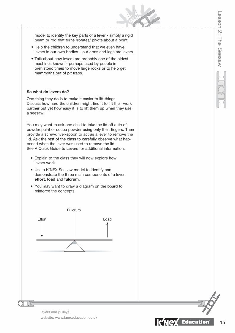
model to identify the key parts of a lever - simply a rigid beam or rod that turns /rotates/ pivots about a point.
•Helpthechildrentounderstandthatweevenhave levers in our own bodies – our arms and legs are levers.
•Talkabouthowleversareprobablyoneoftheoldest machines known – perhaps used by people in prehistoric times to move large rocks or to help get mammoths out of pit traps.
So what do levers do?
One thing they do is to make it easier to lift things. Discuss how hard the children might find it to lift their work partner but yet how easy it is to lift them up when they use a seesaw.
Youmaywanttoaskonechildtotakethelidoffatinof powder paint or cocoa powder using only their fingers. Then provide a screwdriver/spoon to act as a lever to remove the lid. Ask the rest of the class to carefully observe what hap-pened when the lever was used to remove the lid.See A Quick Guide to Levers for additional information.
• Explaintotheclasstheywillnowexplorehow levers work.
• UseaK’NEXSeesawmodeltoidentifyand demonstrate the three main components of a lever: effort, load and fulcrum.
• Youmaywanttodrawadiagramontheboardto reinforce the concepts.
levers and pulleys
website: www.knexeducation.co.uk
Lesson 2: The Seesaw
Education®

16
Teacher’s Notes The children should be aware of the weight, or force, made by the weighted paper cup on their hand. The activity also provides an opportunity to introduce children to the idea that weight is also a force. The effect of using a weight is the same as pushing down with a finger.
It may be useful to create a word board with cards that have the word on one side and a short explanation on the reverse side for children to use when needed.
Working in Groups of 2-3 •Askeachgrouptopreparestickersandlabeltheir seesaw model.
F - Fulcrum
L – Load
E – Effort
Each group will need 2 paper cups (or pieces of foil) and some weights (paper clips/coins/standard weights).
1. Feel the load: •Askonechildfromeachgrouptoplacethebackoftheir hand and arm on the desktop. Another member of the group then places the paper cup/foil containing the weights on the fingers of their partner’s hand who then lifts the cup up from the surface of the desk. Each child tries the exercise in turn.
•Whatdidtheyfeel?
•Didthecupfeelheavy?
2. Use the lever: • Askeachgrouptoplacetheweightedpapercupatone end the seesaw. What happens to the end of the seesaw with the load attached to it? Each child in turn pushes down at the opposite end and notices what happens to the load. Possible questions to ask:
•Diditfeeleasierormoredifficulttolifttheweighted paper cup this time?
•Whatwasthedirectionmovedbytheirpush(effort)?
•Whatwasthedirectionmovedbythepapercup(load)?
• Askthechildrentotaketheirlabelsandplacethemin the appropriate locations on the model to identify the fulcrum, load and effort. Ask the groups to make and add two arrow labels to their models to show the direction of movement of the effort and load forces.
An alternative method is to wrap the weights/coins in foil and attach the foil parcels to the seat of the seesaw with an elastic band. If you use elastic bands in the classroom please review the safety guidelines, outlined at the beginning of this guide, regarding their safe use by the children.
Talk about how one end of the seesaw goes down when the weighted paper cup is placed at the load end but will not move until there is a push (an applied effort) at the opposite end. To lift the load up they must push down. In other words, the lever has helped change the direction of the movement and the applied force. The use of the directional arrows may help the children visualise what is happening as they record their observations and make labelled drawings of their model.
Lesson�2.1�and�2.2:�The�Seesaw
Education®

17
levers and pulleys
website: www.knexeducation.co.uk
Lesson 2: The Seesaw
• Talkabouthowleverscanbefoundeverywhere,butthey do not all look like seesaws. Other examples of levers include scissors to cut paper, a claw hammer to pull a nail out of piece of wood, a stapler, an oar used to row a boat and even their own arms and legs.
Extension Activity 1Some children may feel it was easier to move the paper cup using the lever than without it. Discuss how they might be able to carry out a fair test to verify their ideas.
Teacher’s Notes If time allows ask children to investigate levers on selected Internet web sites. For example www.enchantedlearning.com/physics/ machines/levers.shtml
The children could be asked to come up with different ideas to measure the load and effort. These ideas might include using non-statutory measurements such as the number of paperclips/coins in each paper cup, or using force meters.
• Askthechildrentodescribeandexplaintheir observations in written text and/or verbally. They should include labelled drawings of their model with arrows to indicate movements and use the correct terminology to describe the different components.
To promote the wider use and application of ICT skills and practices, the children’s models and work could be recorded using a digital camera.
Extension Activity 2Discuss what rules the children would have to make if three of them were to use a seesaw at the same time. Where would they have to sit? How might they use their K’NEX seesaw model to test their ideas?
Lesson 2.2 for Key stage 2Possible Teaching and Learning ActivitiesThe following activities are more suitable for older Key Stage 1 or early Key Stage 2 children. The starting point is the K’NEX Seesaw model used in the previous lesson.
Working in Groups of 2-3Making lifting and moving easier: • Askeachgrouptomodifytheirseesawmodelsothat the load is positioned closer to the fulcrum.
• Explaintothechildrenthefulcrumisnow‘off-centre’, making the arms unequal in length. In the original model the fulcrum is positioned in the centre of the beam, making the arms equal in length.
• Askthechildrentopredict,givingtheirreasons,if this change will make any difference in the effort they need to use to lift the load. How will they test their predictions? Write their predictions on the board for later discussion.
The children could be asked to work the modification out for themselves or they could be told to replace the yellow Rods on the load side with shorter blue or white ones.
You may wish to review what the children did in 1: ‘Feel the load’ and 2: ‘Use the lever’ described in Lesson 2.1.
Education®

18
• Tryitandsee.Weretheirpredictionscorrect? Teacher’s Notes The children should find that it requires a much smaller effort (a push or weighted paper cup) to lift the load. If they use the weighted paper “effort” cup from the earlier activity they will find it is too heavy.
At this point you may wish to introduce the idea of input, process and output as applied to machines. In the case of a lever: • the input is the amount and direction of the effort force • the process is the lever mechanism and • the output is the direction and amount of force produced at the ‘load’ end of the lever beam.
• Askthechildrentousewrittentexttodescribe and explain their observations. They should include labelled drawings of their model with arrows to indicate movements and they should use the correct terminology to describe the different components.
To promote the wider use and application of ICT skills and practices, the children’s models and work could be recorded using a digital camera.
Whole Class
•Discusshowitnowrequiresmuchlessefforttoliftthe load when the effort is applied a greater distance from the fulcrum than the load.
•Thisformofleverdesigndiffersfromthatoftheseesaw in which the load and effort are applied equidistant from the fulcrum.
•Talkabouthowmuchthe‘effort’endnowmoves compared to the ‘load’. This demonstrates another function of levers - to increase (amplify) or decrease movements depending on which end of the lever is used to apply the effort.
Lesson�2.1�and�2.2:�The�Seesaw
Education®

19
Lesson 2: The Seesaw
•Askthechildreniftheythinkitwillbehardertoliftthe load when it is placed a long distance from the fulcrum. Explain that they can reverse the load and effort ends of their seesaw lever model. Reposition the labelling stickers to the new arrangement and repeat the activities as before.
•Askthechildrentodescribeandexplaintheir observations. They should include labelled drawings of their model with arrows to indicate movements and use the correct terminology to describe the different components.
Extension Activity 1Ask the children to use a force meter to measure the effort force needed to lift the load in the three different situations outlined above. If two force meters are available per group, one force meter could be used to apply the load and the other force meter could be used to measure the effort.
Record the results on the board and discuss the results.
PlenaryHave a quiz on levers in which the children must use the correct technical vocabulary.
Ask the children to identify ‘levers in action’ from a collection of common devices used in school and at home. The names of the devices are written on cards, which are placed face down on a desk. A child selects a card naming the lever device to which they must respond. They must describe what the device is used for, how it works and be able to identify the load, fulcrum and where the effort is applied.
Teacher’s Notes Children are often surprised how much effort is needed to lift a load positioned a long way from the fulcrum, especially when effort must be applied close to the fulcrum. The other surprise comes when the load end pivots round very quickly, often hitting the back of their hand. To explore this further, some groups could be asked to use blue Rods and others white Rods instead of the yellow ones in the original building plans.
levers and pulleys
website: www.knexeducation.co.ukEducation®

20
Lesson�3:�The�Balance�1st Class Lever
Time for each lesson: 1 - 1.5 hours
LearningObjectives - Children should learn: •toobserveanddescribemovements,directionandtypes of forces working in a lever mechanism
•torelatesciencetothewaysinwhichfamiliar machines work
•tocarryoutasimpleinvestigation
Vocabularybalance, unbalanced, lever, pivot, fulcrum, beam, load, effort, direction, movement, up, down, weight, mass, level, force, Newton, friction, opposes, motion, gravity, horizontal, stationary
ResourcesEach group of 2-3 children will need:• 1 K’NEX Understanding Mechanisms: Levers and Pulleys kit and Building Instructions booklet• Dot stickers or pieces of masking tape• Felt-tipped pens• Washers, paperclips (all of an equal size) or slotted gram masses to hang from the balance arms• Ruler
Useful Internet Web Sites:Please refer to Page 10 of A Quick Guide to Levers.
Possible Teaching and Learning ActivitiesIntroductionThe activities outlined in this lesson may be used to support the QCA/ DfEE Exemplar Scheme of Work for: Design and Technology Unit •1A:Playgrounds •1D:MovingPictures •3C:MovingMonsters •4B:Storybooks •5C:MovingToys •6C:Fairground Science Units •1E:PushesandPulls •2C:ForcesandMovement •6E:BalancedandUnbalancedForces
Whole Class •Talkabouthowbalancesandotherweighingdevices with which the children may be familiar from other lessons, (for example: mathematics), have been used for centuries. Help the children to understand that distributing weight equally, using a form of balance, can also make it easier to carry heavy loads. Ask the children to look at the man in the photograph on Page 4 of the K’NEX Building Instructions booklet.
Teacher’s Notes The large load is split into two equal portions and evenly balanced across his shoulders.
Education®

21
•Askthemwhyitmightbeeasierforhimtocarryloads in this way. What would happen if the man’s load were not balanced on each side of the pole?
Working in Groups of 2-3 •Explainhowtheclasswilldiscoverhowabalance works by building and investigating a K’NEX model balance.
•AskeachgrouptobuildtheK’NEXBalancemodel shown on Pages 4-5 of the Building Instructions booklet. Allow them time to investigate how their model works.
Whole Class
•TalkaboutthesimilaritiesbetweentheK’NEXBalance model and the Seesaw model, investigated in a previous lesson.
•Discusshowthebalanceisanexampleofalever.
•Askthechildrentopreparestickylabelsandusethem to identify the different parts of their balance model.
F = Fulcrum L = Load E = Effort Beam
•(Optional)Explainhowthebalanceandseesaware examples of a 1st Class lever and that there are 3 different types of levers: 1st Class, 2nd Class and 3rd Class levers. Tell the children that they will be able to investigate the different lever types in other lessons.
Working in Groups 2-3 • Askthechildrentoremovethegreyhangingtrays(grey pulley wheels) from their model and push the red and orange hangers to the end of the balance arms.
• Oncethetwoarmsarestationary,askthechildrento observe and describe what the model is doing, using the correct vocabulary.
• Whathappenswhenoneendofthebalancearmis given a small push/has a force applied?
• Thechildrenshouldbeaskedtoexplaintheir observations.
• Discusshowthisactivitydemonstratesthatanobject will remain stationary until a force acts on it.
Teacher’s Notes The balance model does not move because the forces acting on both arms are balanced. When a force is applied to one side it will move because the forces are now unbalanced. The arm to which the force has been applied moves in the direction of the applied force. If a weight is used, instead of a push, it will also causes the arm to move. Weight is also a force.
The balance will remain stationary, or at rest, until a weight is loaded on one side or a force is applied to one side. If that weight or force is larger than the weight or force on the opposite side then the forces acting on the balance arm will become unbalanced and the
Teacher’s Notes If the load is not balanced evenly, one side will hang down lower than the other and make it difficult to carry.
Lesson 3: The Balance
levers and pulleys
website: www.knexeducation.co.ukEducation®

22
Teacher’s Notes If time allows you may wish to demonstrate other examples of objects that remain stationary and have clearly identifiable and familiar forces acting on them. For example, an object suspended from a string, thread or elastic band will remain in that position. If, however, the weight of the object is increased, a point will be reached at which the string will break and the object will fall. At the point at which the string breaks, the forces acting on it are unbalanced. In other words, the weight of the object (load) is now greater than the resistance (load bearing capacity) of the string.
Talk about how mechanisms such as levers (balances) and familiar playground equipment or machines also need to have forces applied to them to make them move. All machines need a force to be applied to them to make them work.
• Askthechildrentoidentifywhatotherforcesmayhave acted on the balance to stop it moving.
* What force slows up the arms and eventually stops them moving?
* Frictioninthepivotjointand air resistance.
Friction is the force that opposes movement. In the pivot joint, friction has the effect of slowing down the movement. It acts just like a brake. If both arms are of equal weight, then the force due to gravity acting on both sides will be equal and, in theory, the arms will come to rest in a horizontal position.
* Why do the arms eventually stop in a horizontal position?
* Both arms are equal in weight and so the forces acting on each side are equal.
* What force is acting on each arm now? * Gravity.
balance arm will move in the direction of the larger force. This is a general law of physics.
Lesson�3:�The�Balance
Education®

23
Exploring the K’NEX balance model • Replacethehangingtrayssothattherearetwopulleys on one side and one on the other side. Push both hanging trays to the end of their arms and observe, record and explain what happens.
• Posethequestion,“Whatdoyouhavetodotobalance the forces in the model?”
Teacher’s Notes The children should note that the heavier tray goes down while the lighter tray moves up. They should also report that this is the result of unbalanced forces in action.
The children may either add, or remove, a grey pulley to one or the other side in order to make the weights on both sides equal. The children should be encouraged to discuss their observations in terms of balanced and unbalanced forces.
• Askthechildrentoreturntotheir‘unbalanced’model with two grey pulleys on one side and one on the other to find a different way to balance their model without adding or removing grey pulleys. They can slide the hanging trays along the arms.
The children should be able to find that by sliding the heavier hanging tray closer to the fulcrum, the balance model will again become balanced.Discuss the children’s findings with those obtained in a previous investigation of the K’NEX Seesaw (Lesson 2.2: Making lifting and moving easier) in which they discovered that a small effort applied a long distance from the fulcrum can be used to lift a heavier load positioned close to the fulcrum.
Whole Class • Askthechildreniftheirresultsmightsuggestageneral rule for making a balance work.
• Discusswiththeclass
•Howwilltheytesttheirrule?
•Whatwilltheymeasure?
•Howmanyreadingsdotheyneedtotake?
•Howwilltheyrecordtheirresults?
If time permits, each group could work individually. Alternatively, the class could share results leading to a general class discussion on their interpretation.
You may also decide to suggest that the children use a table template, such as the one shown on Page 24, in which to record their results.
levers and pulleys
website: www.knexeducation.co.uk
Lesson 3: The Balance
Education®

24
Lesson�3:�The�Balance
Younger children might use squared graph paper to record and visualise their results.For example:The children measure the relative distance they placed the grey K’NEX pulley hangers, the number of washers or paperclips or the value of the masses used to balance their model, in the appropriate distance measurement, as measured from the fulcrum. The blue connecting Rod on the hangers could be placed through the washers or paper clips to prevent them falling off.
For those children who are unable to come up with their own ideas, you might suggest they keep one K’NEX pulley at one end and find the positions on the other arm to balance 2, 3 and 4 K’NEX pulleys.
Using squared graph paper:
Using a template:
Education®

25
• Discusstheresultsoftheirinvestigationinwhichthey explored balancing the forces acting on the model. They should have found that when balanced, the forces on one side must equal the forces on the opposite side.
• Askthechildrentomakelabelleddrawingsoftheir balance model showing the positions of the fulcrum, effort and load and the directions in which the forces are acting. They should describe and explain their observations using appropriate scientific and technological vocabulary.
Problem solving activityChildren could be set the task of applying their rule to find the weight of an unknown object using only one 10g mass.
Plenary Ask some children to describe and explain how they solved the weighing problem.
Teacher’s Notes To promote the wider use and application of ICT skills and practices, the children’s models and work might be recorded using a digital camera.
levers and pulleys
website: www.knexeducation.co.uk
Lesson 3: The Balance
Education®

26
Lesson�4:�The�Wheelbarrow�2nd Class Lever
Time: 1 - 1.5 hours
LearningObjectives - Children should learn: •torelatesciencetothewaysinwhichfamiliar machines work
•tocarryoutasimpleinvestigation
Vocabularylever, pivot, fulcrum, beam, handles, effort, load, lift, weight, force, Newton, heavy, object, force meter, design specification, compare, modify, 1st Class lever, 2nd Class lever, labelled drawings
ResourcesEach group of 2-3 children will need:• 1 K’NEX Introduction to Simple Machines: Levers and Pulleys kit with Building Instructions booklet• Dot stickers or pieces of masking tape• Felt-tipped pens• Aluminium foil or cling film • A pile of small washers, paper clips or plastic beads or other small objects that are awkward to carry by hand• Force meters
Useful Internet Web Sites:Please refer to Page 10 of A Quick Guide to Levers.
Possible Teaching and Learning ActivitiesIntoduction
In this lesson children investigate the science used in the design of a wheelbarrow and how knowledge and under-standing of the lever principle can help them modify and improve its design for a different purpose.
Whole class •Explainthatalthoughleverscomeindifferentforms, they all use the same basic principle: if a heavy object (load) is positioned close to the fulcrum, less force (effort) is needed to move it.
For example, a door, a paper guillotine, a stapler and nutcrackers all make use of the lever principle but they all have very different functions.
•Askthechildrenifitiseasiertoopenadoorbypushing close to the hinge or at the handle? Explain that the door hinge is the fulcrum, the weight of the door is the load and the effort is applied where you push. Review their findings from previous lessons – if the effort is applied a long way from the fulcrum work will be easier.
Teacher’s Notes If time is available, or as prior learning in an ICT lesson, children could use the Internet to research different uses of levers.
Education®

27
Whole class •Reviewhow,inpreviouslessons,thechildren investigated the type of lever used in a seesaw and a balance. Explain that in this lesson they will investigate a different type of lever and discover how it operates in a wheelbarrow. Children may be familiar with a wheelbarrow but they may not recognise it as a lever in action.
Working in Groups of 2-3 •AskeachgrouptobuildtheirK’NEXwheelbarrowmodel and investigate how it works.
•Thechildrenshouldlinethetrayoftheirwheelbarrow with aluminium foil or cling film. This will prevent the washers, or other small objects, from falling out as they are moved in the wheelbarrow.
•Questionstoask:
•Whatarewheelbarrowsusedfor?
•Whattypesofloadsarenormallycarried in wheelbarrows?
•Howarewheelbarrowsloadedandunloaded?
•Howgoodisthewheelbarrowdesignforits intended purpose?
•Howgoodisthewheelbarrowforliftingandmoving heavy loads? (If they did not have a wheelbarrow how might they lift and move a heavy load?).
• Thechildrenshouldbeencouragedtorecord,describe and explain their observations, using labelled drawings where possible.
• Askthechildrentoinvestigatethewheelbarrowasa lever and to identify and label the positions of the fulcrum, load and effort on their model using the dot stickers or masking tape labels.
• Whatarethedesignfeaturesthatmakeawheelbarrow a good machine for lifting and moving heavy loads?
• Reviewwiththechildrenhowtheydiscoveredinthe seesaw and balance investigations that a large weight/force close to the fulcrum could be moved by a smaller weight/force further away from the fulcrum.
• Howdothepositionsoftheeffort,fulcrumandload compare to those they found in their K’NEX balance and seesaw models?
Teacher’s Notes To promote the wider use and application of ICT skills and practices, the children’s models and work might be recorded using a digital camera.
Wheelbarrows are normally used to carry loose materials such as sand, soil or rubble. The wheel not only reduces friction and makes it easier to move over surfaces, but it also acts as a pivot to tip up the wheelbarrow to empty it. The tray has a sloping front end to make it easier to tip out the loose materials.
The handles used for lifting the load are placed much further from the fulcrum than is the load being carried.
Force meters could be introduced to enable the children to compare the force needed to vertically lift the wheelbarrow with its load, versus the force needed to lift the load using the handles.
In wheelbarrows the load is positioned between the lifting effort force and the fulcrum. This means that the lifting force will always be amplified. The load and the effort also move in the same direction.
Lesson 4: The Wheelb
arrow
levers and pulleys
website: www.knexeducation.co.ukEducation®

28
Lesson�4:�The�Wheelbarrow�
Teacher’s Notes The wheelbarrow, although a lever in action, is a different type of lever from that found in the balance and seesaw. In those simple machines the fulcrum is between the effort and load. Talk about how both types of levers share the same features – a rigid beam that rotates about a fulcrum, effort and load.
See the ‘A Quick Guide to Levers’ for additional information.
Whole Class • (Optional)Explainhowleverscanbeclassified,usingthe relative positions of the effort, fulcrum and load, into 1st, 2nd and 3rd Class levers.
The seesaw and balance are examples of 1st Class levers in which the fulcrum is between the effort and load. In 2nd Class levers the load is between the fulcrum and effort.
See the ‘A Quick Guide to Levers’ for additional information.
If time is available, or in a prior ICT lesson, children could use the Internet to research different uses of 2nd Class levers. For example: a door, stapler, bottle opener and nutcrackers.
Working in Groups of 2-3 • Whatotherexamplesof2ndClassleverscanthe children find in the classroom, at home or from an Internet search?
• Identifythepositionsofthefulcrum,loadandeffort and explain how each machine works and why it is a 2nd Class lever.
Extension Activity 1Design problem • Anewwheelbarrowisneededtomoveevenheavier loads. What changes should be made to their present design to enable it to move heavier loads without increasing the effort needed to lift the handles.
• Howwillthechildrentesttheirdesigntoensurethatit meets the new design brief?
• Theyshouldbeabletodescribeandexplainwhytheir design will be able to lift and move heavier loads.
• Thechildrenshouldbeencouragedtouselabelled drawings wherever possible.
To promote the wider use and application of ICT skills and practices, the children’s models and work might be recorded using a digital camera.
2nd Class Lever
Education®

29
Extension Activity 2The wheelbarrow without a wheelIf time is available, or during an ICT lesson, children could use the Internet to research the “travois”.
Not all cultures used the wheel to help move heavy loads. Many nomadic peoples used a different method, similar in principle to the wheelbarrow, but without the wheel. For example, Native Americans on the Great Plains used the ‘tra-vois” to move their household belongings. This device is a frame made from a pair of long poles hitched to a dog or horse. The load is strapped across the poles, while the ends of the poles simply drag along the ground behind the animal. It is easy to assemble, to take apart when not in use, to repair and makes use of readily available materials.Discuss how the travois design compares with that of the wheelbarrow. The children might consider how they are used and how they meet the needs of the users and identify their similarities and differences.
PlenaryShare designs, features and discuss the science behind a good wheelbarrow design.
levers and pulleys
website: www.knexeducation.co.uk
Lesson 4: The Wheelb
arrow
Education®

30
Lesson�5:�The�Ice�Hockey�Stick�3rd Class Lever
Time: 1 - 1.5 hours
LearningObjectives - Children should learn: •torelatesciencetothewaysinwhichfamiliar machines work
•tocarryoutasimpleinvestigation
•tocarryoutaproblemsolvingactivity
Vocabulary3rd Class lever, pivot, fulcrum, effort, load, resistance, handle, weight, force, object, stationary, rest, still, design, specification, compare, labelled drawings, balanced, unbalanced, friction, air resistance, fair test
Possible Teaching and Learning Activities
IntroductionThe activities in this lesson may be used to support the QCA/DfEE Exemplar Scheme of Work for Science: •Unit4:Friction •Unit6E:BalancedandUnbalancedForces
Whole Class • Discusshowthereareanumberofsportsthatuse clubs, bats or sticks to strike balls or other objects, either over a long distance or at high speed. Examples include sticks to score goals in ice hockey, or bats to hit the ball to the boundary in cricket.
ResourcesEach group of 2-3 children will need:• 1 K’NEX Introduction to Simple Machines: Levers and Pulleys kit with Building Instructions booklet• Dot stickers or pieces of masking tape• Felt-tipped pens• Measuring tape
You will need:• Hockey stick (if possible) and other examples of sports equipment such as a cricket bat or tennis racquet
Teacher’s Notes See: A Quick Guide to Levers for additional information.
Education®

31
Teacher’s Notes The wrist of the hand holding the top of the ice hockey stick is the fulcrum, the lower hand provides the effort and the resistance of object being hit is the load.
The children may not realise at first that it is their wrist that is the fulcrum. Their wrist provides the point of rotation, just like a door hinge.
• Introducetheactivitybytellingthechildrentheice hockey player in the photograph on Page 8 of the K’NEX Building Instructions needs an improved design for his hockey stick to help him score more goals. He knows that he isn’t hitting the puck fast enough but he is not sure whether he needs to buy a longer or a shorter hockey stick. The children’s task is to provide evidence to help him make his decision.
• TheywillhaveavailableaK’NEXmodelofhisicehockey stick which they can use to test their ideas.
• Talkabouthowanicehockeystickisyetanothertype of lever and that the concepts they learnt in previous lessons also apply. Review the key points about levers:
•theyallsharethesamebasicfeatures–arigidbeam that rotates about a fulcrum, effort and load.
•whenaheavyobject(load)ispositionedclosetothe fulcrum, less force (effort) is needed to move it.
Working in Groups of 2-3 • AskthechildrentofirstbuildtheirK’NEXHockeystick model, and then investigate, describe and explain how it works as a lever.
• UsethephotographonPage8oftheBuilding Instructions to observe the position of the player’s hands.
• Letthechildrentrythisforthemselvesbyhittingsmall balls of paper with their K’NEX ice hockey stick.
* Which hand acts as the fulcrum?
* Can you identify exactly which part of that hand is the fulcrum?
* Which hand provides the effort (the force that moves the puck)?
* Where is the load?
* The top hand.
* The wrist.
* The lower hand.
* The puck.
Try this:Working in Groups of 2-3 • AskonechildtoholdtheirK’NEXicehockeystickand line it up along the edge of their desktop.
• Usingonlytheirwrist,theyshouldmovetheicehockey stick backwards and forwards.
Depending on the flexibility of their wrists, the head of the ice hockey stick should move about 4 times the distance moved by the hand.
Lesson 5: The Ice Hockey S
tick
levers and pulleys
website: www.knexeducation.co.ukEducation®

32
Lesson�5:�The�Ice�Hockey�Stick
• Theirpartnermarksthestartandstoplinesand measures the distances moved by the head of the hockey stick and their partner’s hand.
• Theirwristmovementisessentiallythesameasadoor opening on a hinge.
Teacher’s Notes The fulcrum is the wrist, the effort is provided by the lower hand on the stick and the load is the ball of paper or ice hockey puck.
It remains at rest/stationary until it is hit with the ice hockey stick. It then moves away very quickly in the direction in which it was hit, gradually slows down and finally stops.
• Askeachgrouptousedotstickersormaskingtape to label the positions of the fulcrum (F), load (L) and effort (E) as well as the direction of the forces involved (using arrows) on their model.
Whole Class (Optional Activity) • Talkaboutwhathappenstotheballofpaperorice hockey puck before and after it is hit with the stick.
• Discusstheconceptofbalancedandunbalancedforces. Ask the children to describe and explain the effect of balanced and unbalanced forces in this activity.
• Just before the paper ball is hit, its weight will be balanced by the reaction of the floor that supports it. There are no other forces acting on the paper ball so it remains stationary until it is hit by the hockey stick.
• The head of the hockey stick is moving very quickly when it hits the paper ball.
• When a force is applied to the paper ball by the moving hockey stick, it moves off at a fast speed but then slows because of friction between it, the floor and air resistance. Friction and air resistance are forces working in the opposite direction to the movement of the ball. Why might a hockey puck move further on ice than on a floor?
Education®

33
Teacher’s Notes To promote the wider use and application of ICT skills and practices, the children’s models and work might be recorded using a digital camera.
• Askthechildrentodescribeandexplaintheir observations. To demonstrate how a hockey stick works they should use labelled drawings, which include the positions of the fulcrum, effort and load as well as the direction of the forces that are applied.
• Howdothepositionsofthefulcrum,effortandload compare to the other two examples of levers the children have investigated?
In 3rd Class levers the effort is positioned between the load and the fulcrum. This means that 3rd Class levers are not as efficient as the other two lever types because the load will always be further from the fulcrum than the effort. As a consequence, a much larger effort is now needed to move even a small load.
The main advantage of a 3rd Class lever is its use in making the load end move very quickly, as happens in fishing rods, cricket bats, softball bats, tennis racquets and golf clubs.See A Quick Guide to Levers for additional information on the three types of levers.
Further information is also available from the following Internet web sites:
www.howstuffworks.com;
www.enchantedlearning.com/physics/ machines/levers.shtml;
www.flying-pig.co.uk
Working in Groups 2-3 • Remindthechildrenoftheirdesigntask:Toprovide evidence to help the hockey player in the photograph on Page 8 of the Building Instructions decide on the type of stick he needs to improve his hitting capabilities.
• Discussthetaskwiththechildrenandaskthemhowthey will set about their investigation.
•Howwilltheytesttheirdesigns?
•Whatwilltheytest?
•Whatwilltheymeasureandrecord?
•Howmighttheypresenttheirresultswithreferenceto the original design specification?
•Discusstheneedtouseafairtestwithwhichto evaluate their design ideas.
If the children perform their test by hand then each test hit may be different. One possible method to eliminate the variability in the test and allow an equal strength hit on each occasion would be to attach the K’NEX ice hockey stick to a stand and allow it to swing from a mea-sured height. The greater the height from which the ice hockey stick blade swings, the harder will be the hit on the ball. Ask: Do the test balls all need to be the same weight? If not, how might this affect their results? How might they obtain equally weighted paper balls?
3rd Class Lever
Lesson 5: The Ice Hockey S
tick
Education®
levers and pulleys
website: www.knexeducation.co.uk

34
Lesson�5:�The�Ice�Hockey�Stick
Teacher’s Notes A stationary puck requires the application of a great amount of effort (force) in order for it to move from rest to high speed in a very short period of time. A longer stick design makes the head of the stick move much faster than the player’s hands. (Think about the radius of a circle.) A longer hockey stick, however, may make the control of the head movement more difficult. Applying the lever principle: With a longer hockey stick, the load (the puck) will be further away from the fulcrum and it will therefore need more effort (muscle power) to hit it. A shorter stick will require less effort and its movement is more easily controlled. The trade-off is that the hitting head will not move as quickly.
That is the designer’s dilemma - how to make best use of the science.
Extension Activity 1 • Askthechildrentoinvestigateother3rdClasslevers used in sports, such as cricket bats, golf clubs, baseball/softball bats, tennis racquets, and fishing rods. Provide examples of these pieces of equipment for the children to examine.
• Whatdotheplayersneedtobeabletodotomeetthe objectives of the game? How do the designs of the different types of sporting equipment meet the needs of the players?
• AskthechildrentobuildaK’NEXmodelofthedifferent types of sporting equipment they have identified and test their ideas.
PlenaryShare ideas about what makes a good ice hockey stick design. Ask the groups to report back to the class with their recommendation to the player. They should make comments on their designs using the correct technical and scientific language.
Education®

35
Lesson�6:�ScissorsConnected 1st Class Levers
Time: 1 - 1.5 hours
LearningObjectives - Children should learn: •torelatesciencetothewaysinwhichfamiliar machines work
•tocarryoutasimpleinvestigation
Vocabularylever, compound, connected, 1st Class levers, pivot, fulcrum, beam, handles, force, blades, wedge, object, resistance, design, specification, compare, labelled, drawings, shearing, wedges, because, evaluate, modify, modifications
ResourcesEach group of 2-3 children will need:• 1 K’NEX Understanding Mechanisms: Levers and Pulleys kit with Building Instructions booklet• Dot stickers or pieces of masking tape• Scissors• Paper and card of different thickness• Felt-tipped pens• Modelling clay/Plasticine
You will need:• Selection of different types of scissor-like cutting devices. For example, wire cutters, garden shears, pliers, and hair-cutting scissors.
NOTE: These items should be used for demonstration purposes only. Do not give these implements to the children.
Possible Teaching and Learning ActivitiesIntroductionIn this lesson the children investigate a familiar tool and apply their knowledge and understanding of forces when used in the design of a cutting machine – a pair of scissors.
Whole ClassDemonstrate how scissors can be safely used to cut paper and textiles.
Demonstrate how the two blades work: the blades cut across each other in a shearing action.
Teacher’s Notes A pair of scissors uses two simple machine concepts in its design: levers and the wedge. The cutting action itself is produced by the sharpened edges of the blades, which are in fact wedges that work in opposite directions to each other.
Lesson 6: The Scissors
levers and pulleys
website: www.knexeducation.co.ukEducation®

36
Lesson�6:�Scissors
Teacher’s NotesUse a magnifying glass to show children the shape of the cutting edge. The role of the levers is to amplify the squeezing forces from your hand.
See K’NEX Introducing Mechanisms: Wheels and Axles and Inclined Planes Teacher’s Guide for further work on wedges.
The blades cut with great force into the paper and, just like all wedges, move the cut paper edges apart in a sideways direction. This action is similar to an axe splitting wood or a knife cutting an apple into two pieces.
If possible demonstrate how this technology works using the K’NEX wedge model from K’NEX Introducing Mechanisms: Wheels and Axles and Inclined Planes kit.
* At the handles.
* The resistance of the paper or card to the cutting blades.
Some children may observe that they need to use two effort and load labels on their model but only one for the fulcrum. A pair of scissors makes use of two levers working in opposite directions and is an example of compound or connected 1st Class levers.
The hinge (fulcrum) is common to both levers and is positioned between the effort (handles) and the blades (load).
Working in Groups of 2-3Investigating how scissors work •AllowthechildrentimetomaketheirK’NEXscissors model and to investigate its action.
* Ask them what scientific concept is being used when scissors work. You may need to provide them with a clue. Scissors have a hinge or fulcrum about which each blade rotates.
* Where is the effort applied?
* What acts as the load?
•Usedotstickersormaskingtapetolabelthepartsof the scissors: F = Fulcrum L = Load E = Effort Use arrows to show the direction of the applied forces.
Cutting edges of scissors.
The sideways movement of a wedge.
Education®

37
Teacher’s NotesSee A Quick Guide to Levers for additional information.
You may find it useful to draw a diagram on the board to illustrate this arrangement.
•Askeachgrouphowtheymighttestthescissors’ cutting action? Fingers are NOT allowed, even with plastic.
•Whereisthestrongestcuttingactionfound?
•Whereistheweakestcuttingactionfound?
•Askthechildrentodescribeandexplainverballyand in written text, how their K’NEX scissors work. They should be encouraged to use labelled drawings indicating the positions of the fulcrum, effort and load and the direction of the applied forces.
Whole Class •Showthechildrenaselectionofotherscissor-like cutting tools with which they may be familiar and which have a similar cutting action to scissors.
•Discusshowallthecuttingtoolshavethesamebasic design but that the design has been modified to make each of them meet different needs.
•Foreachcuttingtoolinturnask:
•Whattypesofmaterialisthistooldesignedtocut?
•Wouldscissorsbeabletocutthesematerials? If not, why not?
•Howdoesthedesignofthiscuttingtoolallowitto cut materials that scissors cannot?
•Askthechildrentomakelabelleddrawingsofthe different types of cutting tools, indicating the position of the fulcrum, effort and load. They should make short notes to describe how the design of the cutting tool fits them for the jobs for which they are used.
You might suggest using thin rolls of modelling clay/Plasticine and use the indentation made by the cutting blades as a possible measure of the cutting forces made by the blades.
To promote the wider use and application of ICT skills and practices, the children’s models and work might be recorded using a digital camera.
Cutting tools with short blades and long handles are used to cut difficult materials such as wire or thick branches. The long handles help amplify the squeezing force (effort), while the short blades mean that the load, or resistance, is near the fulcrum or hinge. This posi-tion is where the cutting forces are greatest. Remind the children about their investigations when using their K’NEX scissors to cut modelling clay.
Hair cutting scissors, on the other hand, have long blades and short handles because the main need is to make long straight cuts. You do not need a lot of cutting force to cut through hair.
levers and pulleys
website: www.knexeducation.co.uk
Lesson 6: The Scissors
Education®

38
Lesson�6:�Scissors�
Teacher’s NotesTo promote the wider use and application of ICT skills and practices, the children’s models and work might be recorded using a digital camera.
Design TaskAsk the children to modify the design of their K’NEX scis-sors model so that it has a much stronger cutting or gripping action. With the aid of a labelled drawing of their design, they should write a description of how their design works and state how their modifications have made the cutting action stronger. They should also include the results of any tests they carried out.
Extension Activity 1If time is available the children might be asked to transfer theirdesignintoresistantmaterials.Youmightaskthem, for example, to make a pair of tongs from wood and other appropriate materials that can pick up and hold an object weighing 200g or more. What is the greatest weight their tongs can lift?
PlenarySelect some models to share with the class and ask the children to describe: •Thereasonsbehindtheirdesign.“Wedidthis because…”
•Whytheirdesignworksbetterthattheoriginalmodel.
•Thepartsoftheirdesignthatpleasethem.
•Whatteststheycarriedouttoevaluatetheirdesign against the design brief.
Education®

39
A�Quick�Guide�to�Pulleys
A pulley is a very simple type of mechanism; it has been used for thousands of years to make easier the job of lifting heavy objects. The simplest type of pulley mechanism is a single pulley.
When a single pulley is used as a lifting device, the effort force needed to raise the load must be equal to or just greater than the load. In theory the effort needed to lift the load is the same as if the load was lifted directly from the ground without using a pulley. In prac-tice, however, the effort force must be greater than that of the load in order to overcome the added effects of friction in the system.
Key elements of a pulley mechanism • Pulley - a freely revolving wheel with a groove in its outer rim through which a rope, cable or chain can be passed.
• Effort – the pulling force applied to the rope to lift the load.
• Load – the weight of the object to be moved by the effort force.
One way of getting bricks to the top of a building is to pull them vertically upwards. This method requires a great amount of hard work. Using a single pulley mechanism, however, allows heavy objects to be lifted by pulling down on a rope from below. This is an easier and safer way to raise the load of bricks than to be on the roof pulling them up. So how does it work?
What is a pulley?A pulley is a mechanism that can change the direction of an effort, or pulling force, applied to a rope. This means that a pull down may be converted into a pull up. Pulleys can also be used to amplify the applied effort force. Passing a rope over the rim of a revolving wheel or pulley helps to reduce the amount of friction in the system.
A Q
uick Guid
e to Pulleys
What can pulleys be used for?Pulleys can: • Changethedirectionoftheapplied effort force 1. A downward pull on the rope running over a single fixed pulley results in an upward movement of the load.
levers and pulleys
website: www.knexeducation.co.ukEducation®

40
2. Pulleys can also be used to move loads horizontally using a vertically applied effort force. A downward pull on a rope attached to a pulley system, can move a clothesline horizontally.
Multiple pulleys and cables are found in systems used to lift very heavy loads. A multiple or compound pulley system is called a block and tackle. Using multiple pulleys amplifies the effort force still fur ther so making the job of raising the very heavy loads easier to do.
Why is it called a block and tackle? The block is the frame that holds the pulleys and the tackle is the rope or cable.
• Amplifytheappliedeffortforce As more pulleys are used in a pulley system, less effort is needed to move or lift a load, but a longer amount of rope must be pulled through the system. This is the trade-off. Less effort is needed but it is applied over a longer distance.
For example, in a system composed of 2 pulleys – one upper pulley that is fixed and one lower, movable pulley – you only need apply half the effort force that would otherwise be needed to raise the load if pulleys were not used. The distance you must pull the rope, however, will be dou ble the distance moved by the load.
Sailboats and yachts make much use of these types of pulley systems to handle and control large heavy sails.
A�Quick�Guide�to�Pulleys
Education®

41
levers and pulleys
website: www.knexeducation.co.uk
A Q
uick Guid
e to Pulleys
Key facts about pulleys:Single or fixed pulleyExamples: flagpole, clothesline, painter’s platform.
A single fixed pulley must be attached to a frame and the pulley wheel can rotate freely to reduce friction.
Fixed pulleys change the direction of the applied effort force.
The load moves the same distance as the effort force.
Using a fixed pulley, however, enables you pull down and to use gravity to your advantage by allowing you to add your body weight to the effort made by your arm muscles, so making it appear to be easier to lift the load.
When a single pulley is used as a lifting device, the effort force needed to raise the load must be equal to or just greater than the load. In theory the effort needed is the same as if the load was lifted directly from the ground. In practice, however, the effort has to be greater than the load in order to overcome friction in the pulley system. Using a rotating wheel is one way of reducing friction.
Movable PulleysWhen two pulleys are used, the upper pulley must be fixed to a frame while the lower movable pulley is attached to the load it lifts. The two pulleys are connected by a single continuous rope and when the rope is pulled down, the lower pulley moves upwards taking the attached load with it.
Fig. 1
The advantage of a pulley can be seen when you compare using a fixed pulley to lifting from above. When lifting from above you can only use muscle power to pull the load upwards, all the time working hard to overcome the effects of gravity.
Fig. 2
Movable pulleys amplify the applied effort force. As more pulleys are used, less effort is needed to raise the load, but the rope must be pulled through a greater distance.
Education®

42
A�Quick�Guide�to�Pulleys
In the example shown in Fig. 2, two pulleys are used. The weight of the load being raised is distributed equally between the two parts of the rope on either side of the movable pulley. The force needed to hold the system in balance or to raise it is now only half that of the load. The downside is that the effort force must move twice as far as the load. For example, to lift a 20N load a height of 3cm. the 10N effort force must move a distance of 6cm.
Compound PulleysCompound pulleys are made from two or more sets of pulleys connected by the same rope. The upper set is made from fixed pul-leys attached to a frame, while the lower set is made from movable pulleys. Effort is applied by pulling down on the rope or chain. Compound pulleys not only change the direction of the applied force but they also increase the force applied to the load.
As more pulleys are used, less and less effort is needed to lift heavy loads. In Fig. 3, the K’NEX block and tackle model has 4 strings supporting the two lower movable pulleys. The number of supporting strings equals the number of times the pulley system multiplies the effort force.
If the load to be lifted by the K’NEX block and tackle model is 4N, then the effort force required to lift it will be 1N. This is because the load is divided between four parts of the rope, each part carrying a quarter of the load.
If the load is raised 1cm, the cumulative effect on the distance moved by the effort will be 4 x 1cm. In this example the effort will move 4 times the distance moved by the load.
Fig. 3
Education®

43
Lesson 7: The Flagpole
Lesson�7:�The�FlagpoleA Fixed Pulley System
Time: 1 - 1.5 hours
LearningObjectives - Children should learn: •pulleysarewheelswithgroovesaroundtheirouterrim
•pulleyscanbeusedtoliftobjectsandchangethe direction of movement
•torelatesciencetothewaysinwhichfamiliar machines work
•tocarryoutasimpleinvestigation
Vocabularypulley, wheel, groove, rim, fixed, pull, force, lift, raise, lower, gravity, rotary, motion, linear, load, effort, Newtons, measurement, opposite, direction
ResourcesEach group of 2-3 children will need:• 1 K’NEX Understanding Mechanisms: Levers and Pulleys kit with Building Instructions booklet• Dot stickers or pieces of masking tape• Felt-tipped pens• Measuring tape or rulers• Coloured paper or cloth• Coloured crayons or pencils• Scissors• Stapler, glue or tape• 200g slotted weights• 1 small bucket or basket filled with heavy objects• String/rope • Broom handle
Possible Teaching and Learning ActivitiesIntroductionThe activities in this lesson may be used to support the QCA/DfEE Exemplar Scheme of Work for: Design and Technology Unit •2C:WindingUp Science Units •1E:PushesandPulls •2C:ForcesandMovement •6E:BalancedandUnbalancedForces
Whole Class/Demonstration: • Reviewwiththechildrenhowmanyofthesimple machines they have investigated make it easier to lift heavy objects.
• Askforavolunteer(s)tobend,facedown,overa table/desk, next to one edge, and reach down on the side of the table/desk to lift a bucket or basket filled with heavy objects. (Children should not extend an arm over the front of the desk).
• Askthevolunteertodescribehowdifficult(oreasy) this was for them.
• Securearopetothebucketandaskthemtopullitup using the rope.
• Encouragethechildrentoconsiderwaysinwhichthis could be done more easily. For example: place a broom handle across two desks and loop the rope over the handle. The volunteer can now pull down on the rope instead of pulling up. Does this arrangement make it easier or more difficult to lift the load? Record their suggestions/answers on the board for later reference and discussion.
• Explainthattheirtaskistobuildamodelthatwill demonstrate the use of a simple machine called a pulley that can make the job of raising an object easier.
levers and pulleys
website: www.knexeducation.co.ukEducation®

44
Working in Groups of 2-3 • AskthechildrentobuildtheK’NEXFlagpolemodel, (Pages 10-11 of the Building Instructions booklet), and allow them time to investigate how it works and what it does.
• Withthehelpofalabelleddiagramdrawnontheboard, discuss how a pulley wheel works and how the rope fits into the groove in the rim of the wheel.
Whole Class • ExplainhowtheirK’NEXFlagpolemodelprovidesan example of a FIXED pulley. This is a pulley that does not move when the rope is pulled, although the wheel may spin in place.
• Askthechildrenwhytheythinkflagpolesmakeuseof pulleys to raise and lower a flag.
• Howwouldtheygetaflagtothetopofthepoleifthey did not use a pulley?
• Wherehavethechildrenseenotherexamplesofthis type of pulley being used?
Teacher’s Notes The children should not cut the string in this model. A long string will be needed for subsequent pulley building activities.
See: A Quick Guide to Pulleys and Key Technical Terms and Scientific Definitions for additional information.
It is easier and safer to pull down on a rope to raise a flag than it is to climb a tall ladder to secure the flag to the top of the pole.
Possibly on cranes, washing lines, on equipment in the school gym, or classrooms.
Free photographs of pulleys in action on cranes can be obtained from www.freefoto.com
How many different types of machines do the children know about that use pulleys in their mechanisms?
What do these machines do?
A pulley is a wheel with a groove around its outside edge into which a rope or belt can fit. By pulling down on one end of the rope a load on the other end can be lifted. Pulleys can be used to change the direction of movement and can make it easier to lift heavy objects. Children will be able to explore different types of pulley systems during the next few lessons.
For additional information please refer to A Quick Guide to Pulleys and Key Technical Terms and Scientific Definitions.
Internet Web site on pulleys: www.howstuffworks.com and search ‘pulleys’.
Lesson�7:�The�Flagpole
Education®

45
* Amplifying forces to help lift heavyobjectsusinglittleeffort.
* The circular motion of a motor is transferred to wheels or cylinders.
* Changing the direction of movement.
Some examples you may want to discuss with the children include:
* liftingheavyobjects,asincranesorrunningaflag up a flagpole.
* transferring movement and forces in sewing machines and vacuum cleaners.
* moving equipment in the gym or even opening and closing curtains.
NOTE: Care should be taken when pulling down on the string so it does not slip. The string should be grasped just belowthepulleyandpulleddownSLOWLY.
• Doesthepulleymakeliftingthemasseasier?
* What types of movement are produced by pulley systems?
* (i) Linear: by the moving load and the pulling force. (ii) Rotary: by the pulley wheel.
Working in Groups of 2-3(If the children have added the string to their flagpole, ask them to remove it before beginning this next activity.) • Askthechildrentocompletethefollowing:
Step 1: Attach a slotted mass to one end of the string and simply lift it vertically by hand. Ask them to feel how much force or effort is needed to lift the mass. What happens when they let go of the string?
Step 2: Pass the string over the pulley. Lift the mass by pulling the string. Feel how much force is now needed to lift the mass.
The pulling force is the effort, while the mass being lifted is the load. This is the same as in levers. When using the fixed pulley the children pull down on the string to raise the mass. It is easier to pull down on the string using a pulley because “body” weight can also be used to help the pulling forces. (Ask them to remember the demonstration at the beginning of the lesson when a pupil reached down to lift up a heavy load.) When pulling directly upwards only “muscle” power can be used. In fact, the same amount of effort is used in both cases.
• Askthechildrentousestickerstolabelthefixedpulley and the directions of movements of the effort and load.
levers and pulleys
website: www.knexeducation.co.uk
Lesson 7: The Flagpole
Education®

46
Lesson�7:�The�Flagpole
• Howmightthechildrenmeasuretheforcesneeded? Teacher’s Notes A force meter could also be used for these activities to enable the children to take direct measurements. If you have not already done so, demonstrate how a force meter is used to measure forces and explain that the unit of mea-surement is Newtons (N).
Step 3: Ask the children to repeat Step 2 but only this time they should measure the distances moved by their hand (the effort) when pulling on the string and the distance moved by the mass (the load). One child should grip the string just below the pulley and pull down slowly to lift the load. Another child then measures: (i) how far the string has been pulled
(ii) how far the load has been raised above the desktop.
• Whatdotheirmeasurementstellthemabouthowa fixed pulley works?
To lift a load the children would have to pull on the rope with at least as much force as the weight of the load. They might test this by connecting a force meter to either end of the pulley rope, pulling each force meter and recording the reading.
The distance moved by the effort and the load is the same. If force meters have been used then, in theory, the values obtained for the effort force and load should also be the same. In reality, however, the effort force is likely to be larger because of the additional effect of friction in the pulley system. Fixed pulleys only change the direction of movement or the applied force; they do not amplify the force.
• Askeachgrouptorecordandexplaintheirfindingsand observations by writing and making labelled drawings. They should indicate the direction of the applied forces, the direction of movement of the pulling force and the object being raised. The children should be encouraged to use the correct scientific vocabulary.
To promote the wider use and application of ICT skills and practices, the children’s models and work might be recorded using a digital camera.
Teacher’s Notes When the load is pulled upwards, the pulling force is greater than the weight of the object – the forces are unbalanced. When the object is held still, the forces are balanced – it is not moving. The force applied on the rope end equals that of the weight on the other end. When released it falls because there is now no upward pull-ing force but only the force of gravity pulling it downwards.
Optional Activity for Step 3 • Askthechildrentodescribewhattheyhaveobserved in terms of balanced and unbalanced forces.
Education®

47
Extension Activity 1Working in Groups of 2-3 • Askthechildrentodesignaflagfortheirflagpoleusing coloured paper or cloth, felt-tipped pens or crayons.
• Howaretheygoingtoattachtheirflagtothestringso that it is also easy to remove?
• Howcantheymakesuretheflagcanopeninabreeze?
OR
Alternative activityWorking in Groups of 2-3Design a flag code message system to be used to send and receive short secret messages to and from another group.
PlenaryDiscuss what the children have learnt about pulleys and how they are used, using vocabulary that relates to the science and technology they discovered.
To promote the wider use and application of ICT skills and practices, the children’s models and work might be recorded using a digital camera.
If possible, retain a flagpole model, with its fixed pulley, so that the children can compare it with the compound pulley system used in the sailboat model.
levers and pulleys
website: www.knexeducation.co.uk
Lesson 7: The Flagpole
Education®

48
Lesson�8:�The�Sailboat��A Compound Pulley System
Time: 1 - 1.5 hours
LearningObjectives - Children should learn: •torelatesciencetothewaysinwhichfamiliar machines work
•tocarryoutasimpleinvestigation
Vocabularypulleys, fixed, movable, force, effort, load, double pulley sys-tem, single pulley system, com-pound, compare, doubled, amplify, because, trade-off, pull, force meter, prototype, Newton, friction, lift, lower, raise
Possible Teaching and Learning ActivitiesIntroduction
Whole class •Reviewwiththechildrenhowtheuseofapulleysystem helps make the job of raising a flag to the top of a pole easier. In this case, the pulley is used to change the direction of the effort force – it is easier to pull down on a rope than to pull up on one. Using a pulley system also means that you do not have to climb a ladder to reach the top of the pole.
ResourcesEach group of 2-3 children will need:• 1 K’NEX Introduction to Simple Machines: Levers and Pulleys kit with Building Instructions booklet• Dot stickers or pieces of masking tape• Felt-tipped pens• Measuring tape or rulers• Coloured paper or cloth• Coloured crayons or pencils• Scissors• Stapler, glue or tape• 200g slotted masses or 5 Newton force meter• Large paperclips
You will need:• The K’NEX flagpole model• Pictures of sailboats and sailing ships available for the children to view• Additional lengths of string for Extension Activity 2 (optional)
Teacher’s Notes More information on pulleys is available from A Quick Guide to Pulleys and the Internet web site www.howstuffworks.com
Education®

49
Teacher’s Notes Free photographs can be obtained from www.freefoto.com and http://pics.tech4learning.com/
• Askthechildrentolookatthepicturesofdifferent sailing boats. Talk about how, regardless of the size of the sailboat, sailors have always been faced with the same problem: how to lower and raise heavy sails safely. In days of large sailing ships sailors had to climb the masts and literally pull up large, heavy sails by hand – it was very dangerous work. Modern sailboats use pulley systems that allow the crew to raise and lower sails quickly without leaving the (relative) safety of the deck.
• Thislessoninvestigateshowpulleyscanbeusedto lift heavy objects.
• Askthechildrentocollect/findpicturesoflifting machines from books or from research using the Internet.
• Discusshowpulleyscanbeusedinanumber of situations.
• Allowthechildrentimetoinvestigatephotographsor illustrations of lifting machines that use pulleys.
• Whatarethesemachinesusedfor?
• Howheavyaretheloadstheylift?
• Isthereanyconnectionbetweenthesizeoftheloads and the number of pulleys and ropes/cables they use?
Working in Groups of 2-3 • AskthechildrentoconstructtheK’NEXSailboat model shown on Pages 12-13 of the Building Instructions booklet.
Building Tip: Building Steps 6 – 8 will require cooperation between the members of the group. This applies particularly to Step 7 when string is attached to the pulleys. Make sure that one child holds the movable pulley (built in Step 6) while another carefully threads the string around the pulley wheels.
Remind the children that they should NOT cut the string. They will need a long string for several other pulley activities.
• Allowtimeforthechildrentoinvestigatehowthesail mechanism works by lifting a mass attached to the lower pulley. An opened, large paperclip could be used as a hook.
Talk about how machines that are used to lift heavy weights usually have numerous pulleys in the lifting mechanisms. The greater the number of pulleys that are used, the easier it becomes to lift heavy loads.
In this model pulley system there are two pulleys, an upper fixed pulley and a lower movable pulley. Two ropes are attached to the lower movable pulley. This arrangement is called a double, or compound, pulley system.
Fixed pulley
Movable pulley
Lesson 8: The Sailb
oat
levers and pulleys
website: www.knexeducation.co.ukEducation®

50
Lesson�8:�The�Sailboat
•Askthechildrentoconsiderhowthelowerpulleydiffers from the pulley wheels at the top of the mast. Talk about the concept of movable pulleys.
•Whatdotheynoticeaboutthedistancesmovedbythe lower pulley wheel and the end of the rope? Are they the same as in the flagpole model, or different? If possible, have the flagpole model available for comparison.
•Whatdotheynoticeabouttheeffortforcesneeded to pull the string to raise the load? How do their findings compare with what they found using the flagpole model?
•Usestickerstoidentifyandlabelthefixed and movable pulleys and the directions of movement observed.
•Askthechildrenhowtheymighttesthowwelltheir pulley system works? Discuss how they might measure the forces used? How many measurements do they need to take?
• Askeachgrouptorecordandexplaintheirfindings and observations through writing and labelled drawings. They should indicate the direction of the applied forces, the direction of movement of the pulling force and the object being raised. The children should be encouraged to use correct scientific vocabulary.
Teacher’s Notes The distance moved by the effort or pulling force - the child’s hand pulling the string – is twice that moved by the load but the pulling force needed to move the load is halved.
This is the trade-off. The pulling force (effort) needed is halved but the distance it has to move is doubled.
It may be necessary to review that forces are measured in Newtons (N) and if weights are used, how their values can be converted into Newtons. Alternatively, two force meters may be used - one to measure the downward pulling force and the other the force that is to be overcome.
To promote the wider use and application of ICT skills and practices, the children’s models and work might be recorded using a digital camera.
Education®
51
Extension Activity 1Working in Groups of 2-3If time is available, ask the children to design a sail for their sailboat using appropriate materials. The children could use photographs of sailboats to research ideas for sail designs and shapes. • Howwillthesailbeattachedtotheirmechanismfor raising and lowering?
• Howwillthesailbe‘fixed’inpositionwhenithas been raised?
Extension Activity 2Design Task - Working in Groups of 2-3Their sailboat needs to be rigged for use by a crew with physical disabilities. The task is to design a sail handling system to raise and lower two sails, one fore and one aft, which can be operated from the deck.
They can only use the contents of the kit to make their prototype.
Allow the children time to select, measure and make a sail from suitable textiles. • Howwilltheyattachthesailto (i) the raising mechanism (ii) the sail boom?
• Howdorealsailboatsdothis?
• Cantheymakeuseofthe“flagpole”mechanism?
The children should be encouraged to draw plans for their design, indicating how they think it will work.On completion ask: • Whatchangesdidyoumakeduringthetestingof your design?
• Whatwerethemostdifficultpartstomake?
• Howdidyousolvetheproblems?
PlenaryReview what the children have learnt about movable and fixed pulleys and how, when fixed and movable pulleys work together, they form a compound pulley system.
Note: The “rope” that comes with the kit should not be cut, so an alternative will be necessary.
To promote the wider use and application of ICT skills and practices, the children’s models and work might be recorded using a digital camera.
levers and pulleys
website: www.knexeducation.co.uk
Lesson 8: The Sailb
oat
Education®

52
Time: 1 - 1.5 hours
LearningObjectives - Children should learn: •toobserveanddescribemovementsinasimplemachine
•torelatesciencetothewaysinwhichfamiliar machines work
•tocarryoutasimpleinvestigation
Vocabularyblock and tackle, pull, pulley, fixed, movable, force, effort, load, counterbalance, counterweight, balanced, unbalanced, lever, modify, evaluate, amplify, trade-off, topple, unstable, stability, compare, because
Possible Teaching and Learning ActivitiesIntroduction
Whole class •Discussand/orreviewthechildren’sprevious experiences in which they discovered a connection between the number of pulleys used in a pulley system and the amplification of the pulling force – the greater the number of pulleys used, the easier becomes the lifting job.
•Show,oraskthechildrentofind,photographsand pictures of cranes at work.
•Askthemtodescribethepulleyssystemstheyuseand the jobs they have to do?
•Howdotheythinkthesepulleyssystemsmakeiteasier to lift heavy loads?
ResourcesEach group of 2-3 children will need:• 1 K’NEX Introduction to Simple Machines: Levers and Pulleys kit with Building Instructions booklet• Dot stickers or pieces of masking tape• Felt-tipped pens• Measuring tape or rulers• Paper cup• 200g slotted masses • Large paperclips• 2 x 5 Newton force meters (optional)
Teacher’s Notes Photographs of cranes can be obtained from www.freefoto.com. and http://pics.tech4learning.com/
www.freefoto.com has some good photographs of a giant float-ing crane pulling the Gateshead Millennium Bridge in place.
Internet research: www.howstuffworks.com.
For additional information on pulleys see A Quick Guide to Pulleys.
Lesson�9:�The�Block�and�Tackle�A Compound Pulley System
Education®

53
Teacher’s Notes The correct answer is 4 times. The multiplication can be found by counting the number of lengths of rope supporting the movable pulleys. In this example there are 2 movable pulleys, each with two supporting ropes = 4. (The three pulleys at the top of the structure are fixed pulleys.)
See: A Quick Guide to Pulleys.
Whole class • Introducetheactivitiesbyexplaininghowthecranes use ‘block and tackle’ mechanisms to lift very heavy loads and how a block and tackle can make the job of lifting heavy objects easier.
• BeforebuildingtheirK’NEXBlockandTacklemodel ask the children to look at the plans for their model on Page 15 of the Building Instructions booklet.
• Explainhowtheblockandtackleisconstructedby winding the rope around a number of fixed and movable pulley wheels.
• Howmanytimesdotheythinktheliftingforcewillbe increased by this pulley system?
Working in Groups of 2-3 Let’s Investigate • AskthechildrentoconstructtheirK’NEXBlockand Tackle model and allow them some time to investigate how it works.
• Askeachgrouptoidentifyandlabelthefixedand movable pulleys in their model.
• Howdothechildrenthinkusinganumberoffixedand movable pulleys in a lifting mechanism will affect its ability to lift a load?
• Askeachchildinturntoplaceapapercupcontaining one or more 200g masses on the palm of his or her hand and to raise and lower it. This will allow them to gain some impression of the load being lifted by their model and the forces needed to raise it.
• Suggestthechildrentryliftingthepapercupusingthe K’NEX Block and Tackle model.
•Askwhathappenedtotheirmodelwhentheyfirst tried to lift the weighted paper cup?
•Askthechildrentoexplaintheirobservations.
•Whatotherscienceconceptisworkinghere?
•Howmighttheysolvetheproblem?
Force meters could be used to record the actual forces needed to lift the weighted paper cup vertically. These can then be compared with those needed when using the block and tackle.
The K’NEX Block and Tackle model becomes unstable and will topple forwards as the weighted paper cup is lifted. When the load is lifted off the desktop the structure acts like a lever that pivots around its front edge. The front edge becomes the fulcrum and if the weight of the load is greater than the weight of the model, the model will topple in the direction of the load. The forces in the system have become unbalanced.
A counterweight is needed to balance the weight of the load being lifted. The folder shown in the photograph on Page 15 of the Building Instructions booklet is acting as the counterweight.
Lesson 9: The Block and
Tackle
levers and pulleys
website: www.knexeducation.co.ukEducation®

54
Lesson�9:�The�Block�and�Tackle�
In cranes the counterweight is very heavy because it must be placed close to the fulcrum. Ask the children to identify the positions of the counterweights in the photographs of cranes they have found.
Teacher’s notes: Investigating Further There are two approaches you might consider using:
a) Building on earlier lessons, ask the children to plan their own tests, including measurements to be taken and data logging techniques. Children could use rulers and measuring tapes to measure the distance moved by the effort and load. Force meters could be used to record the effort force.
(b) Directed investigation
• Askthechildrentoplacetheweightedcupinthebasket and pull on the string to lift it.
b) Direct the children as to what they should do.
Investigating Further • Explainthatastheyusetheblockandtacklemodelto lift a load the children should try to discover answers to the following questions:
•Whatdidtheyfindoutabouttheamountofeffort needed to lift the load?
•Howdoesthelifting‘power’ofthismodelcompare to the other pulley models?
•Howdoesthepulleysysteminthismodeldifferfrom the other pulley models they have investigated?
(a) Planning their own tests • Askthechildrenhowwilltheytesttheirideas.
• Encouragethemtoplanandexplaintheirtestsbefore carrying them out.
• Whatmeasurementsdotheyneedtomake? How will they take their measurements?
• Howwilltheyrecordtheirresults?Inatable?
• Referthembacktowhattheydidinearlierlessons on pulleys.
Education®

55
Teacher’s Notes Force meters could be used to compare the actual forces needed to lift the weighted paper cup verti-cally with those needed when using the K’NEX block and tackle model.
An alternative approach could be to use two force meters - one representing the pulling force, or effort, and the other the load to be overcome by the effort.
• Feeltheforceneededtolifttheweightedpapercup.
• Howdoesliftingtheweightedpapercupwiththeblock and tackle compare to lifting it directly by hand?
• Countthenumberofstringssupportingthelower movable pulleys. What might this information tell you about how much this block and tackle system helps you to lift the load?
• Usingtheblockandtackle,raisethecupabout5cm. Measure how far the string must be pulled to allow the paper cup to reach this height?
For either approach:
• Askthechildrentodescribeandexplaintheir observations, to make labelled drawings of their model and use arrows to indicate movements. They should be encouraged to use the correct terminology to describe the different components.
Extension Activity 1Design Task Working in Groups of 2-3The present lifting mechanism is not safe when in use. Modify the design so that it will not topple when lifting heavy objects.
The children should be encouraged to (i) draw plans for their design (ii) explain how they will evaluate it (iii) write a description of how they think it will work.On completion ask: •Whatchangesdidyoumakeduringthetestingof your design?
•Whatwerethemostdifficultpartstomake?
•Howdidyousolvetheproblems?
The children should notice a significant reduction in the effort needed to lift the weighted cup when using the block and tackle. They should also observe that there are 4 strings supporting the two lower movable pulleys. This system makes it 4 times easier to lift the weighted paper cup load, but the ‘trade-off’ is they have to pull the string 4 times the distance moved by the load.
To promote the wider use and application of ICT skills and practices, the children’s models and work might be recorded using a digital camera.
Extension Activity 2Design TaskWorking in Groups of 2-3Yourmotherisaphysicaltherapistworkingwithpeople who have been injured and have to use wheelchairs. It is often difficult for your mother to lift the patients out of their wheelchairs to use the machines for their exercises. Using K’NEX and other appropriate materials, design and make a portable pulley system that can lift patients out of their wheel chairs and transport them to the different exercise machines. Explain how your machine operates and how it uses pulleys to accomplish the task.
levers and pulleys
website: www.knexeducation.co.uk
Lesson 9: The Block and
Tackle
Education®

56
Lesson�9:�The�Block�and�Tackle�
Plenary Discuss what the children have learnt in the lesson using the words relating to the science and technology they discovered.
Ask them what they think the effect of adding more pulleys to their block and tackle might be on its lifting ability.
Talk about patterns that may be arising in their results fromthisandotherlessons.Youmaywanttodiscuss,forexample, how simple machines help to make jobs easier to do by increasing/amplifying applied forces, but note that there is a trade-off. Using a simple machine can mean that they expend less effort BUT they have to apply the effort over a longer distance.
Education®

57
This list of key terms is intended as background information. While we recognize that some of these terms are not fundamental to National Curriculum requirements for Key Stage 2 Design and Technology and Science, we have nevertheless included them here to help you better understand some of the concepts investigated in the K’NEX Understanding Mechanisms kits.
SIMPLE MACHINEA simple tool used to make jobs easier to do. For example, a lever allows you to apply a small force to move a much larger load. Try pulling a nail out of a piece of wood without a claw hammer. A claw hammer uses the lever principle in its design. Other examples of simple machines are wheels and axles, pulleys, inclined planes or ramps, wedges, and screws. Simple machines can be used to increase forces or change the direction of a force needed to make an object move. They are simple because they transfer energy in a single movement.Simple machines make it easier for you to do jobs by changing the way in which jobs can be done; they cannot change the job to be done. For example, you can load a heavy object onto the back of a lorry by lifting it the short vertical distance – a process that will require a lot of effort. Alternatively, you can take the take the longer but easier route up a ramp with the object. Either way, the job is done.
In science, when an object is moved by a force work is said to have been done. Simple machines make it easier for you to do work. Some simple machines allow a small force to move a large load and are called force amplifiers. For example: crowbars and wheelbarrows.Other simple machines can be used to convert small, slow movements into large, faster movements. Such machines are distance or speed amplifiers. A fishing rod used to cast a hook, or a mediaeval throwing machine, such as a trebuchet, are examples of this application.
COMPOUND MACHINES These have two or more simple machines working together in their mechanism. For example, two 1st Class levers make up a pair of scissors, or pliers, while a complex car engine may be made from several hundred mechanisms.
WORKWork is a scientific concept and is only done when a force moves an object in the same direction as the applied force.
If you push against an object and it does not move then, from a scientific point of view, you will not have done any work. For example, no matter how hard you push in an attempt to move a car while its brakes are on, you will have not done any work if it has not moved. Once, however, the brakes have been released and the car starts to move, then you will be doing work. The amount of work you do depends on the magnitude of the force you apply and the distance you move the object.
Key Term
s and S
cientific Definitions
Key�Technical�Terms��and�Scientific�Definitions
levers and pulleys
website: www.knexeducation.co.ukEducation®

58
Work=ForcexDistancemovedbytheobjectinthedirectionoftheforceor
W = F x d
If the force is measured in newtons (symbol N) and the distance is in metres (m) then the work done (W) is measured in newton metres (Nm).
The SI unit of work is the joule (J) and 1joule=1newtonmetre.
FORCEA force is a push or a pull which, when applied to an object, can make it change shape, move fasterorslower,orchangedirection.Youcannotseeforcesbutyoucanfeelorseetheireffects.A force has both size and direction. The size of a force is measured in newtons (N) and can be measured using spring balances called force meters or Newton meters.
EFFORT The force you apply to move one part of a simple machine, i.e. the input force that is applied to a simple machine, or mechanism, to make it do work. With a wheel and axle simple machine, the effort force can be applied to either the wheel, or the axle, in order to make the other part move. Think of a waterwheel being turned by a millstream or a car axle driving the road wheels.The function of a simple machine, or mechanism, is to transfer the force both to the location and in the direction in which it is needed to move the load.
LOADThe weight of an object to be moved or the resistance that must be overcome before an object can be moved.
The resistance can be the frictional forces in a mechanism itself or simply the friction between two surfaces.
RESISTANCEThe force that works against the effort. It could be either the weight of the object to be moved and/or frictional forces.
FRICTION The force that occurs when two surfaces rub against each other. Friction tends to slow things down, which means it can be both beneficial and unhelpful. For example: friction is beneficial in the case of brakes applied to the wheels of cars and bicycles to slow them down, but friction between surfaces can also cause wear - tyres wear out. Rough surfaces increase friction, while smooth surfaces reduce it.
Frictionalsogeneratesheat.Youcanfeelthiswhenyourubyourhandstogetherquickly.
Key�Technical�Terms��and�Scientific�Definitions
Education®

Key Term
s and S
cientific Definitions
59
levers and pulleys
website: www.knexeducation.co.uk
MECHANICAL ADVANTAGEMost machines are designed to make jobs easier to do. For example, a wheelbarrow that allows you to move a heavy load of soil or a winch used to lift a heavy object. When a machine enables you to use a small effort to move a large load, that machine has given you a “mechanical advantage” you would not otherwise have had. How large or small a mechanical advantage a machine provides can be measured by comparing the load you can move with the effort you used to move it.
The calculation used is:
The mathematical calculation indicates how many times the machine multiplies the effort force.
For example, if a machine allowed you to move a load of 300N using a 100N effort force, the mechanical advantage of the machine will be 3:1 or simply 3.
If the value of the MA is greater than 1 then your machine allows you to move a large load using an effort force less than that of the load. Does this mean you can get something for nothing? Can you get more from less? Unfortunately this is not the case. While a high MA value means you can use less effort force than that of the load to be moved, the distance moved by the effort will be much greater than that moved by the load. This is the trade-off. Remember, simple machines and mechanisms can make it easier to do a job by changing the way in which the job is done; they do not change the actual job to be done. The work needed to be done will always remain the same, so that to move a load, you can use a large effort applied over a short distance, or a small effort applied over a longer distance. It all balances out in the end.
MECHANISMS Although designed and made to do different jobs and make jobs easier to do, all mechanisms share some common features.
•Theyaremadefromsimplemachines,eitherusedsinglyorincombination. •Theyinvolvesomeformofmotion. •Theyneedaninputforcetomakethemwork. •Theyproduceanoutputforceandmotionofsomekind.
Mechanical Advantage (MA) = Load Effort
Education®

Key�Technical�Terms��and�Scientific�Definitions
60
One form of motion (input) can be converted into another (output) through the use of a mechanism (process).
TYPES OF SIMPLE MACHINES •Lever: A rigid beam, bar or rod that turns, or rotates, about a fixed point called the fulcrum. For example: a child’s seesaw.
•Wheelandaxle: A round disk (wheel) with a rod (axle) rigidly connected through the centre of the wheel so that they both turn together. A wheel can be used to turn an axle or an axle can be used to turn a wheel. For example: a winch raising a bucket from a well. The wheel can be a solid, circular disk, such as a car wheel, but it can also be the circular path made by a handle that turns, such as a lever rotating around a fixed point.
•Gear: This is not a simple machine but it could be thought of as a wheel with teeth around its outer rim. Gears are used to transfer motion and force from one location to another, change the direction of rotational motion and amplify the force applied to do a job.
•Rotary: This can be seen in the movement of car, bicycle and gear wheels and in Ferris wheels or carousels as they go round and round on an axis. It is the most commonly occurring type of motion in a mechanism.
•Oscillating:This is an alternating, or swinging to and fro, type of motion. It can be observed in car windscreen wipers, children’s swings or in pendulums as they move backwards and forwards in an arc.
•Linear:This is motion occurring in a straight line, in one direction. Examples include the linear movement of a paper trimmer, a sliding lock, or a conveyor belt.
• Reciprocating: This involves an alternate backward and forward motion, in a straight line, as in the movement of a sewing machine needle or the pistons of a car engine.
TYPES OF MOTION4 basic forms of motion are used in mechanisms:
Education®

61
levers and pulleys
website: www.knexeducation.co.uk
Key Term
s and S
cientific Definitions
•Pulley: A wheel with a groove in its outer rim that spins freely on an axle. A rope, cable, or chain runs in the wheel’s groove and may be attached to a load. As the wheel turns, the rope moves in either direction so that a pull down on one side will raise an object on the opposite side of the wheel.
•FixedPulley: A pulley attached to a solid surface; it does not move when the rope is pulled, other than to turn in place. Fixed pulleys change the direction of an applied force.
•MovablePulleys: A pulley attached directly to the load being lifted; it moves when the rope is pulled.
•CombinationPulleys: A series of fixed and movable pulleys used together to gain the advantages of both in doing the work.
•BlockandTackle: A specific combination of fixed and movable pulleys used to lift very heavy objects; the block is the frame holding the pulleys; the tackle is the rope or cable.
•InclinedPlane: A flat surface with one end higher than the other. The most recognisable form of an inclined plane is a ramp. Ramps make it easier to move from one height to another.
•Screw: A shaft (body) that has an inclined plane spiralling around it. The inclined plane forms ridges (threads) around the shaft to become another simple machine: the screw. It can be used to lift objects or fasten two things together.
•Wedge: A device made of two inclined planes arranged back-to-back. Instead of moving up the slope, wedges themselves move to push things apart. Wedges are inclined planes that move pointed-end first and are used in many cutting tools such as axes, knives and chisels.
Education®