edu34450a 5½-digit dual-display digital multimeter
TRANSCRIPT

Find us at www.keysight.com Page 1
EDU34450A 5½-Digit
Dual-Display Digital Multimeter

Find us at www.keysight.com Page 2
EDU34450A Provides Industry-Grade Measurement Capabilities
The Keysight EDU34450A is a modern digital multimeter (DMM) designed for bench applications.
It measures a broad range of input signals. It features 5½ digits of resolution and up to 110 readings/s
measuring rate for speed-critical tests. It includes generous internal memory, allowing prolonged data
logging of up to 5,000 data points.
With the EDU34450A, you get the benefits of Keysight measurement performance in a low-cost,
compact package.
Combination of hard and soft keys for more intuitive front-panel operation
For easy access to the most frequently used measurement functions, the EDU34450A retains all
the function keys found on a traditional DMM. The function key lights up when pressed to provide
a clear indication of the parameter you are measuring. The intuitive soft keys allow more advanced
configuration when the need arises. Combining these hard and soft keys allows you to quickly set up
and begin your measuring tasks without a steep learning curve.
Standard connectivity to the PC
The DMM has built-in gigabit LAN and USB. The remote connectivity allows you to connect to the
PathWave BenchVue DMM software for more advanced data logging and export logged data.
You can also use the software to retrieve the data saved in the non-volatile memory. Software
drivers are available if you prefer to write your own program, with SCPI commands to control the
DMM and automate your test.
Signature 7-inch dual-measurement color display
The EDU34450A comes with a 7-inch, dual-measurement color display. With this innovation, you can
view your measurement setup, instrument status, reading, and statistics all at once, without flipping
through several screens.
It features a secondary display where you can view primary and secondary components of your input
signal at the same time to help you better understand your device under test.
With the large display, you can set up data logging and view the logged data easily.
USB flash drive adds convenience
The EDU34450A also features a built-in USB memory port, so you can use a USB flash drive to store
your DMM setup. This feature will help you install the same setup in all the DMMs in your lab.
Robust design
We know you can’t afford instrument downtime caused by hardware failures and unscheduled
maintenance. That’s why our engineers designed reliability into the EDU34450A: a rugged enclosure;
state-of-the-art, surface-mount construction throughout; reduced part counts; and rigorous and thorough
testing of all aspects of the product.

Find us at www.keysight.com Page 3
Key features
• Measures 11 input signals:
o DC voltage, DC current, true RMS AC voltage, AC Current, two- and four-wire
resistance, frequency, continuity, diode test, temperature, and capacitance
• Signature 7-inch dual-measurement color display
• Fast reading rate of up to 110 readings/s for speed-critical measurements
• 5,000 points logging memory for recording more data and perform analysis
• Standard USB and LAN for flexible PC connectivity
• USB flash drive support to copy / load configuration for repeated test setup
• Includes PathWave BenchVue DMM software for remote control and data logging

Find us at www.keysight.com Page 4
Simplify Data Gathering and Analysis with PathWave BenchVue DMM Software
PathWave BenchVue software for the PC makes it simple to connect, control, capture, and view
Keysight DMMs with no additional programming.
• Easily log data, screenshots, and system state. Rapidly prototype custom test
sequences.
• Recall the past state of your bench to replicate results.
• Quickly export measurement data in the desired format.
• Quickly access manuals, drivers, FAQs, and videos.
The DMM app in BenchVue allows you to control DMMs to visualize measurements and perform
unrestricted data logging and statistical analysis. The software comes with your EDU34450A purchase.
Record measurements and export results in a few clicks
Quickly log and export data to Microsoft Excel for documentation or further analysis.
Remotely control your DMM via LAN
You can change your instrument settings and perform measurements remotely with built-in LAN
connectivity.
Find us at www.keysight.com Page 5
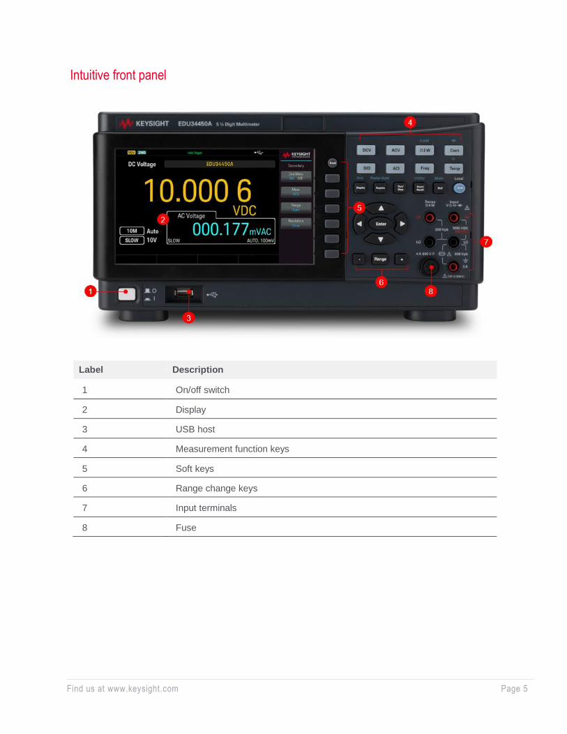
Intuitive front panel
Label Description
1 On/off switch
2 Display
3 USB host
4 Measurement function keys
5 Soft keys
6 Range change keys
7 Input terminals
8 Fuse

Find us at www.keysight.com Page 6
Spec Interpretation Guide
The following pages list the technical specifications for the Keysight EDU34450A DMM. The following
explanations and examples are helpful in understanding how to interpret these specifications:
• Measurement accuracy is specified as the percentage of reading plus the percentage of
range, where reading is the actual measured value and range is the name of the scale
(1 V, 10 V, and so on) — not the full-scale value (1.2 V, 12 V, and so on).
• Accuracies are listed as one-year specifications. This refers to the length of time since
the instrument’s last calibration.
Example 1: Basic DC voltage accuracy
Calculate the accuracy of the following measurement: 9 V DC input, 10 V DC range, one-year accuracy
specifications, standard operating temperature (18 – 28 °C).
From the following page, the one-year accuracy is 0.025% of reading + 0.005% or range.
It translates to this: (0.025/100 x 9 V) + (0.005/100 x 10 V) = 2.75 mV
Total accuracy is 2.75 mV/9 V = 0.0306%.
Example 2: Extreme operating temperature
When the EDU34450A operates outside of its 18 – 28 °C temperature range, you need to consider
additional temperature drift errors. Assume the same conditions in Example 1 but at a 35 °C
operating temperature.
The basic accuracy is again 0.025% of reading + 0.005% of range = 2.75 mV.
Now, multiply the 10 V temperature coefficient from the DC voltage specifications table by the number
of degrees outside of operating range for additional error:
(0.0020% reading + 0.0008% range) / °C x (35 – 28 °C)
= (0.0020% reading + 0.0008% range) / °C x 7 °C
= 0.014% reading + 0.0056% range = 1.82 mV
Total error is 2.75 mV + 1.82 mV = 4.57 mV or 0.0508%.
Example 3: AC voltage accuracy
The AC voltage function measures the true RMS value of the input waveform, regardless of waveshape.
Listed accuracies assume a sine-wave input. To adjust accuracies for non-sinusoids, use the listed crest
factor adder.
For this example, assume a ± 1 V square wave input with a 50% duty cycle and a 1 kHz frequency.
Accuracy for 1 V, 1 kHz sinusoid is 0.2% reading + 0.1% range = 3 mV or 0.3%.

Find us at www.keysight.com Page 7
EDU34450A Accuracy Specifications
Specifications are for 90-minute warm-up time, slow mode, NULL function enabled, and calibration
temperature within 18 – 28 °C (unless stated otherwise).
DC specifications
Accuracy ± (% of reading + % of range):
Function Range 1 Test current or
burden voltage
Input
impedance
1 year
23 ºC ± 5 ºC
Temperature coefficient / ºC
0 ºC – 18 ºC
28 ºC – 55 ºC
DC voltage 100.000 mV - 10 MΩ or > 10 GΩ 0.018 + 0.008 0.0020 + 0.0008
1.00000 V - 10 MΩ or > 10 GΩ 0.015 + 0.005 0.0015 + 0.0008
10.0000 V - 10 MΩ 0.025 + 0.005 0.0020 + 0.0008
100.000 V - 10 MΩ 0.025 + 0.005 0.0020 + 0.0008
1000.00 V - 10 MΩ 0.027 + 0.005 0.0020 + 0.0008
Resistance 2 100.000 Ω 1 mA - 0.065 + 0.010 0.0080 + 0.0008
1.00000 kΩ 500 µA - 0.065 + 0.008 0.0080 + 0.0005
10.0000 kΩ 100 µA - 0.065 + 0.005 0.0080 + 0.0005
100.000 kΩ 10 µA - 0.065 _ 0.005 0.0080 + 0.0005
1.00000 MΩ 1 µA - 0.065 + 0.005 0.0080 + 0.0005
10.0000 MΩ 100 nA - 0.300 + 0.005 0.0250 + 0.0005
100.000 MΩ 100 nA / 10 MΩ - 2.000 + 0.005 0.3000 + 0.0005
DC current 3 10.0000 mA < 0.02 V - 0.10 + 0.015 0.008 + 0.0015
100.000 mA < 0.2 V - 0.10 + 0.007 0.008 + 0.0010
1.00000 A < 0.3V - 0.30 + 0.015 0.019 + 0.0015
3.00000 A < 0.9 V - 0.30 + 0.007 0.019 + 0.0010
Continuity 4 1000 Ω 0.5 mA - 0.1 + 0.1 0.009 + 0.005
Diode test 5 1.0000 V 0.5 mA - 0.05 + 0.10 0.005 + 0.005 1. 20% over range on al l ranges except 1 ,000 VDC and 3 A range. 2. Specifications are for four-wire Ω or two-wire Ω using NULL function. If wi thout NULL function, add 0.2 Ω additional error.
For 1 MΩ, 10 MΩ and 100 MΩ ranges, accuracy may be degraded when humidi ty is > 60 % RH. 3. For 10 mA and 100 mA ranges, al low internal current sense resistor to cool after measuring > 1 A for more than 15 mins. 4. Typical speci fication. Continui ty threshold is f ixed at less than 10 Ω. Avai lable in fast mode only. 5. Typical speci fication. Specifications are for the vol tage measured at the inp ut terminals only. Avai lable in fast mode only.

Find us at www.keysight.com Page 8
AC specifications
Accuracy ± (% of reading + % of range):
Function Range 1 Frequency 1 year 23 ºC ± 5 ºC
Temperature coefficient / ºC
0 ºC – 18 ºC 28 ºC – 55 ºC
True RMS AC voltage 2 100.000 mV 20 Hz – 45 Hz 1.0 + 0.1 0.02 + 0.02
45 Hz – 10 kHz 0.2 + 0.1 0.02 + 0.02
10 kHz – 30 kHz 1.5 + 0.3 0.05 + 0.02
30 kHz – 100 kHz 3 6.0 + 0.3 -
1.00000V to 750.00 V 20 Hz – 45 Hz 1.0 + 0.1 4 0.02 + 0.02
45 Hz – 10 kHz 0.2 + 0.1 0.02 + 0.02
10 kHz – 30 kHz 1.5 + 0.3 0.05 + 0.02
30 kHz – 100 kHz 3 3.0 + 0.3 5 0.10 + 0.02
True RMS AC current 2 10.0000 mA to 3.00000A 6 20 Hz – 45 Hz 1.5 + 0.1 0.02 + 0.02
45 Hz – 1 kHz 0.5 + 0.1 0.02 + 0.02
1 kHz – 10 kHz 7 2.0 + 0.2 0.02 + 0.02 1. 20% over range on al l ranges except ACV 750 V and ACI 3 A. 2. Specifications are for s ine-wave inputs more than 5% of the range, except the 750 V range. Input s ignal must be more than 50 Vrms
for the 750 V range. Maximum crest factor of 3 at ful l scale. Input impedance is at least 1.1 MΩ in paral lel wi th capacitance less than 100 pF, AC couple with up to 400 DCV.
3. Typical speci fication for 100 mV range. Additional error to be added as frequency > 30 kHz and signal input < 10% of range. 30 kHz to 100 kHz: 0.003% of full scale per 4 kHz
4. For input < 200 V rms . 5. For input < 300 V rms. 4.5% of reading + 0.3 % of range for 750 V range (typical speci fication). 6. For 10 mA and 100 mA ranges, al low internal current sense resistor to cool i f appl ied > 1 A for more than 15 mins. 7. Frequencies > 5 kHz are typical for 1 A and 3 A ranges.
Frequency accuracy ± (% of reading + 3 counts):
Function Range 1 Frequency 1 year
23 ºC ± 5 ºC
Temperature coefficient / ºC
0 ºC – 18 ºC 28 ºC – 55 ºC
Frequency 100.000 mV to 750.00 V 20 Hz – 300 kHz 2 0.025 + 3 0.005
10.0000 mA to 3.0000 A 20 Hz – 10 kHz 3 0.025 + 3 0.005 1. The frequency can be measured up to 1 MHz as 0.5 V signal to 100 mV/1 V ranges. 2. 10% of range to ful l -scale input on all ranges , except where noted. 100 mV range specifications are for ful l -scale or greater inputs.
For inputs from 10 mV to 100 mV in 100 mV range, multiply the total percentage of reading error by 10. 3. 10% of range to ful l -scale input on all ranges , except where noted. 10 mA range specifications are for ful l -scale or greater inputs.
For inputs from 1 mA to 10 mA in 10 mA range, multiply the total percentage of reading error by 10.
Frequency resolution:
Function Range Frequency Resolution
Frequency 100.000 mV to 750.00 V 1 0.01200 Hz - 119.999 Hz 0.001 Hz
0.12000 Hz - 1.19999 Hz 0.00001 kHz
1.2000 Hz - 11.9999 kHz 0.0001 kHz
12.000 kHz - 119.999 kHz 0.001 kHz
0.12000 MHz - 1.19999 MHz
0.00001 MHz 1. The frequency can be measured up to 1 MHz as 0.5 V signal to 100 mV/1 V ranges.
Find us at www.keysight.com Page 9
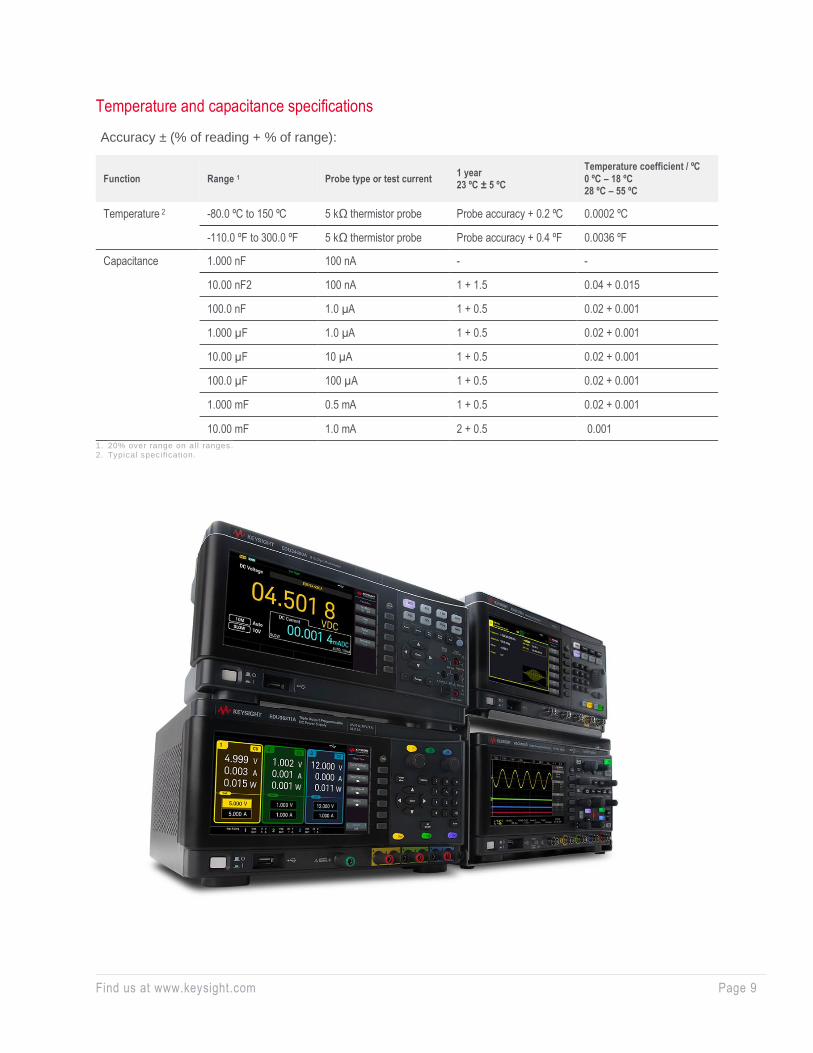
Temperature and capacitance specifications
Accuracy ± (% of reading + % of range):
Function Range 1 Probe type or test current 1 year 23 ºC ± 5 ºC
Temperature coefficient / ºC
0 ºC – 18 ºC 28 ºC – 55 ºC
Temperature 2 -80.0 ºC to 150 ºC 5 kΩ thermistor probe Probe accuracy + 0.2 ºC 0.0002 ºC
-110.0 ºF to 300.0 ºF 5 kΩ thermistor probe Probe accuracy + 0.4 ºF 0.0036 ºF
Capacitance 1.000 nF 100 nA - -
10.00 nF2 100 nA 1 + 1.5 0.04 + 0.015
100.0 nF 1.0 µA 1 + 0.5 0.02 + 0.001
1.000 µF 1.0 µA 1 + 0.5 0.02 + 0.001
10.00 µF 10 µA 1 + 0.5 0.02 + 0.001
100.0 µF 100 µA 1 + 0.5 0.02 + 0.001
1.000 mF 0.5 mA 1 + 0.5 0.02 + 0.001
10.00 mF 1.0 mA 2 + 0.5 0.001
1. 20% over range on al l ranges. 2. Typical speci fication.

Find us at www.keysight.com Page 10
System characteristics
System specifications on single display (typical):
Function Resolution (digit) Function change (sec) 1
Range change (sec) 2
Auto range (sec) 3
Reading rate / sec 4
(USB) Reading rate / sec 4
(LAN)
ACV Slow (5.5) 2.6 2.5 4.6 1.9 1.9
Medium (4.5) 1.2 1.2 1.5 19 19
Fast (4.5) 1.1 1.1 1.2 90 43
DCV Slow (5.5) 1.4 1.4 1.6 1.3 1.3
Medium (4.5) 0.6 0.7 0.8 49 36
Fast (4.5) 0.6 0.7 0.7 110 48
2-wire Ω Slow (5.5) 1.3 2.6 1.6 1.4 1.4
Medium (4.5) 0.7 1.0 0.6 49 36
Fast (4.5) 0.7 1.0 0.5 110 46
4-wire Ω Slow (5.5) 1.8 1.4 1.9 1 1
Medium (4.5) 1.1 0.6 1.1 5.2 5.0
Fast (4.5) 1.1 0.6 1 5.9 5.4
Frequency 5 Slow (5.5) 2.1 2.1 2.6 0.9 0.9
Medium (4.5) 1.2 1.2 1.7 9.0 9.0
Fast (4.5) - - - - -
ACI Slow (5.5) 2.6 2.6 6.2 1.9 1.9
Medium (4.5) 1.2 1.2 1.7 19 19
Fast (4.5) 1.1 1.2 1.3 90 45
DCI Slow (5.5) 1.3 1.3 1.9 1.7 1.7
Medium (4.5) 0.6 0.7 0.9 49 42
Fast (4.5) 0.6 0.7 0.7 110 48
Diode test 4.5 0.1 - - 110 48
Continuity 4.5 0.6 - - 110 47
Temperature 4.5 1.8 - - 4.5 4.2
Capacitance 4.5 - - - - -
1. Time to change from two-wire resistance to this speci fied function and to take at least one reading using SCPI “FUNC” and “READ?” commands.
2. Time to change from one range to the next higher range and to take at least one reading using SCPI “RANGE” and “READ?” commands.
3. Time to automatically change one range and to take at least one reading using SCPI “CONF AUTO” and “READ?” commands. 4. Number of measurements using SCPI “READ?” command when the front-panel display is off using “DISP OFF” command. 5. Reading rate depends on signal frequency ≥ 20 Hz.

Find us at www.keysight.com Page 11
Supplemental measurement characteristics
Measurement Characteristic
DC voltage Measurement method
Input resistance > 10 GΩ (selectable 100 mV, 1 V ranges) 10 MΩ (typical)
Input protection 1,000 V on all ranges (HI terminal)
Resistance Measurement method 2-wire or 4-wire ohms
Open circuit voltage Limited to < 2.8 V
Input protection 1,000 V on all ranges (HI terminal)
DC current Shunt resistance 1 Ω for 10 mA, 100 mA 0.1 Ω for 1 A, 3A
Input protection Externally accessible at front panel 4 A, 600 V fuse for I terminal
Continuity / diode test Measurement method Uses 0.5 mA constant current source
Response time Continuity: 121 samples/second with audible tone Diode: 124 samples/second with audible tone
Continuity threshold 10 Ω fixed
Input protection 1000 V (HI terminal)
Temperature Measurement method 2-wire ohms measurement of 5 kΩ thermistor sensor (YSI 4407) with a 25 ˚C / 125 ˚C ratio of 29.26 Auto-ranging measurement, no manual range selection
Input protection 1000 V (HI terminal)
Measurement noise rejection
CMR (common mode rejection) For 1 kΩ unbalance LO lead
DC 140 dB AC 70 dB
NMR (normal mode rejection) For 60 Hz (50 Hz) ± 0.1%
Slow mode 5½ digits, medium mode: 4½ digits, 60 dB Fast mode: 4½ digits, 0 dB
AC voltage Measurement method AC coupled True-RMS – measures the AC component with up to 400 VDC bias any range
Crest factor Maximum 3:1 at full scale
Input impedance > 1.1 MΩ in parallel with < 100 pF of all ranges
Input protection 750 V rms on all ranges (HI terminal)
AC current Measurement method DC coupled to the fuse and current shunt; AC coupled true-RMS measurement (measures the AC component only)
Shunt resistance 1 Ω for 10 mA, 100 mA 0.1 Ω for 1 A, 3 A
Input protection Externally accessible at front panel 4 A, 600 V fuse for I terminal

Find us at www.keysight.com Page 12
Supplemental measurement characteristics (continued)
Measurement Characteristic
Frequency Measurement method Reciprocal counting technique; AC coupled input using AC voltage function
Signal level 10% of range to full-scale input on ranges except where noted. Auto or manual range selection
Gate time 0.1 second or 1 second gate time
Input protection 750 V rms on all ranges (HI terminal)
Math functions Null, dBm, dB, Min/Max/Avg, hold limit test
Data log Info, list
Triggering and memory Samples per trigger Trigger delay
1 to 5,000 (typical) 0 to 3,600 sec (100 µs step size)
Non-volatile memory 5,000 readings
Sample timer Range Up to 3,600 sec in 100 µs steps
Remote interface USB, LAN standard
Programming language SCPI-1994.0, IEEE-488.2
Rear Panel at a Glance

Find us at www.keysight.com Page 13
General characteristics
Characteristics
Power supply 100 V / 120 V / (127 V) / 220 V / (230 V) / 240 V ± 10% AC line frequency 45 Hz – 66 Hz, automatically sensed at power on
Power consumption 13 VA maximum, < 6.6 W average
Operating environment Full accuracy to 80% RH for 0 ºC to 30 ºC (non-condensing)
Full accuracy to 40% RH for 30 ºC to 55 ºC (non-condensing)
Altitude up to 3,000 meters
Operating temperature Full accuracy for 0 ºC to 55 ºC
Storage temperature - 40 ºC to 70 ºC
Safety compliance IEC 61010-1 / EN 61010-1 Canada: CAN / CSA-C22.2 No. 61010 -1 USA: ANSI / UL std No. 61010-1
Measurement category CAT II, 300 V: CAT I 1000 Vdc 750 Vac rms, 2,500 Vpk transient over-voltages, pollution degree 2
EMC compliance
Compliant to EMC directive (2014/30/EU) Certified to IEC61326-1 / EN61326-1 Group 1 Class A Canada: ICES / NMB-001 Australia / New Zealand: AS / NZS CISPR 11 South Korea KC mark, class A
Shock and vibration Tested to IEC/EN 60086-2
Dimensions (HxWxD) 165 mm x 314 mm x 119 mm (6.5 in x 12.6 in x 4.7 in)
Weight 3.35 kg
Warm-up time 90 minutes
Dimensions (mm)

Find us at www.keysight.com Page 14 This information is subject to change without notice. © Keysight Technologies, 2021, Published in USA, January 11, 2021, 3121-1002.EN
Learn more at: www.keysight.com
For more information on Keysight Technologies’ products, applications or services,
please contact your local Keysight office. The complete list is available at:
www.keysight.com/find/contactus
Ordering Information
Digital multimeter
EDU34450A 5½-digit DMM
Standard shipped items
Power cord, test leads
Keysight optional accessories
EDU190A Instrument stacking kit (to use with other education series instruments)
34138A Test lead set
E2308A Thermistor temperature probe
34330A 30 A current shunt
Other education series products
EDU33211A Waveform generator, 20 MHz, one channel
EDU33212A Waveform generator, 20 MHz, two channels
EDU36311A DC power supply, triple output
EDUX1052A InfiniiVision 1000 X-Series oscilloscope, 50 MHz, analog channels
EDUX1052G InfiniiVision 1000 X-Series oscilloscope, 50 MHz, analog channels, with a built-in
waveform generator
To learn more, please visit:
www.keysight.com/find/EDU34450A