keysight technologies m9181a pxi 6½ digit multimeter
TRANSCRIPT

Keysight M9181A PXI 6½ Digit Multimeter
Calibration and Verification Procedure

2 Keysight M9181A Calibration and Verification Procedure
NoticesCopyright Notice© Keysight Technologies 2011 - 2017No part of this manual may be repro-duced in any form or by any means (including electronic storage and retrieval or translation into a foreign language) without prior agreement and written consent from Keysight Technol-ogies as governed by United States and international copyright laws.
Manual Part Number5185-9181
EditionEdition 3, November 1, 2017
Printed in:Printed in Malaysia
Published by:Keysight Technologies Bayan Lepas Free Industrial Zone, 11900 Penang, Malaysia
Technology Licenses The hardware and/or software described in this document are fur-nished under a license and may be used or copied only in accordance with the terms of such license.
Declaration of ConformityDeclarations of Conformity for this product and for other Keysight prod-ucts may be downloaded from the Web. Go to http://www.keysight.com/go/conformity. You can then search by product number to find the latest Dec-laration of Conformity.
U.S. Government RightsThe Software is “commercial computer software,” as defined by Federal Acqui-sition Regulation (“FAR”) 2.101. Pursu-ant to FAR 12.212 and 27.405-3 and Department of Defense FAR Supple-ment (“DFARS”) 227.7202, the U.S. government acquires commercial com-puter software under the same terms by which the software is customarily provided to the public. Accordingly, Keysight provides the Software to U.S. government customers under its stan-dard commercial license, which is embodied in its End User License Agreement (EULA), a copy of which can be found at http://www.keysight.com/find/sweula. The license set forth in the EULA represents the exclusive authority by which the U.S. government may use, modify, distribute, or disclose the Soft-ware. The EULA and the license set forth therein, does not require or per-mit, among other things, that Keysight: (1) Furnish technical information related to commercial computer soft-ware or commercial computer software documentation that is not customarily provided to the public; or (2) Relinquish to, or otherwise provide, the govern-ment rights in excess of these rights customarily provided to the public to use, modify, reproduce, release, per-form, display, or disclose commercial computer software or commercial com-puter software documentation. No additional government requirements beyond those set forth in the EULA shall apply, except to the extent that those terms, rights, or licenses are explicitly required from all providers of commercial computer software pursu-ant to the FAR and the DFARS and are set forth specifically in writing else-where in the EULA. Keysight shall be under no obligation to update, revise or otherwise modify the Software. With respect to any technical data as defined by FAR 2.101, pursuant to FAR 12.211 and 27.404.2 and DFARS 227.7102, the U.S. government acquires no greater than Limited Rights as defined in FAR 27.401 or DFAR 227.7103-5 (c), as applicable in any technical data.
WarrantyTHE MATERIAL CONTAINED IN THIS DOCUMENT IS PROVIDED “AS IS,” AND IS SUBJECT TO BEING CHANGED, WITHOUT NOTICE, IN FUTURE EDITIONS. FURTHER, TO THE MAXIMUM EXTENT PERMITTED BY APPLICABLE LAW, KEYSIGHT DIS-CLAIMS ALL WARRANTIES, EITHER EXPRESS OR IMPLIED, WITH REGARD TO THIS MANUAL AND ANY INFORMA-TION CONTAINED HEREIN, INCLUD-ING BUT NOT LIMITED TO THE IMPLIED WARRANTIES OF MER-CHANTABILITY AND FITNESS FOR A PARTICULAR PURPOSE. KEYSIGHT SHALL NOT BE LIABLE FOR ERRORS OR FOR INCIDENTAL OR CONSE-QUENTIAL DAMAGES IN CONNECTION WITH THE FURNISHING, USE, OR PERFORMANCE OF THIS DOCUMENT OR OF ANY INFORMATION CON-TAINED HEREIN. SHOULD KEYSIGHT AND THE USER HAVE A SEPARATE WRITTEN AGREEMENT WITH WAR-RANTY TERMS COVERING THE MATE-RIAL IN THIS DOCUMENT THAT CONFLICT WITH THESE TERMS, THE WARRANTY TERMS IN THE SEPARATE AGREEMENT SHALL CONTROL.
Safety Information
CAUTIONA CAUTION notice denotes a hazard. It calls attention to an operating proce-dure, practice, or the like that, if not correctly performed or adhered to, could result in damage to the product or loss of important data. Do not pro-ceed beyond a CAUTION notice until the indicated conditions are fully understood and met.
WARNINGA WARNING notice denotes a hazard. It calls attention to an operating proce-dure, practice, or the like that, if not correctly performed or adhered to, could result in personal injury or death. Do not proceed beyond a WARNING notice until the indicated conditions are fully understood and met.

Trademarks
Microsoft® and Windows® are U.S. registered trademarks of Microsoft Corporation.
PXI is a registered trademark of the PXI Systems Alliance.
Keysight M9181A Calibration and Verification Procedure 3
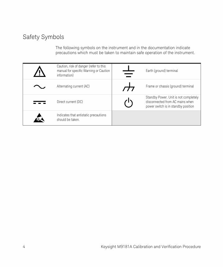
Safety Symbols
The following symbols on the instrument and in the documentation indicate precautions which must be taken to maintain safe operation of the instrument.
Caution, risk of danger (refer to this manual for specific Warning or Caution information)
Earth (ground) terminal
Alternating current (AC) Frame or chassis (ground) terminal
Direct current (DC)Standby Power. Unit is not completely disconnected from AC mains when power switch is in standby position
Indicates that antistatic precautions should be taken.
4 Keysight M9181A Calibration and Verification Procedure

Safety Considerations
Read the information below before using this instrument.
The following general safety precautions must be observed during all phases of operation, service, and repair of this instrument. Failure to comply with these precautions or with specific warnings elsewhere in this manual violates safety standards for design, manufacture, and intended use of the instrument. Keysight Technologies assumes no liability for the customer’s failure to comply with these requirements.
General
Do not use this product in any manner not specified by the manufacturer. The protective features of this product must not be impaired if it is used in a manner specified in the operation instructions.
Before Applying Power
Verify that all safety precautions are taken. Make all connections to the unit before applying power. Note the instrument's external markings described under Safety Symbols.
Ground the Instrument
PXI chassis are provided with a grounding-type power plug. The instrument chassis and cover must be connected to an electrical ground to minimize shock hazard. The ground pin must be firmly connected to an electrical ground (safety ground) terminal at the power outlet. Any interruption of the protective (grounding) conductor or disconnection of the protective earth terminal will cause a potential shock hazard that could result in personal injury.
Do Not Operate in an Explosive Atmosphere
Do not operate the Keysight module/chassis in the presence of flammable gases or fumes.
Keysight M9181A Calibration and Verification Procedure 5

Do Not Operate Near Flammable Liquids
Do not operate the Keysight module/chassis in the presence of flammable liquids or near containers of such liquids.
Do Not Remove Instrument Cover
Only qualified, service-trained personnel who are aware of the hazards involved should remove instrument covers. Always disconnect the power cable and any external circuits before removing the instrument cover.
Cleaning
Clean the outside of the Keysight module, chassis, or accessory with a soft, lint-free, slightly dampened cloth. Do not use detergent or chemical solvents.
Keep Away From Live Circuits
Operating personnel must not remove equipment covers or shields. Procedures involving the removal of covers and shields are for use by service-trained personnel only. Under certain conditions, dangerous voltages may exist even with the equipment switched off. To avoid dangerous electrical shock, DO NOT perform procedures involving cover or shield removal unless you are qualified to do so.
DO NOT Operate Damaged Equipment
Whenever it is possible that the safety protection features built into this product have been impaired, either through physical damage, excessive moisture, or any other reason, REMOVE POWER and do not use the product until safe operation can be verified by service-trained personnel. If necessary, return the product to an Keysight Technologies Sales and Service Office for service and repair to ensure the safety features are maintained.
6 Keysight M9181A Calibration and Verification Procedure

DO NOT Block the Primary Disconnect
The primary disconnect device is the appliance connector/power cord when a chassis used by itself, but when installed into a rack or system the disconnect may be impaired and must be considered part of the installation.
Do Not Modify the Instrument
Do not install substitute parts or perform any unauthorized modification to the product. Return the product to an Keysight Sales and Service Office to ensure that safety features are maintained.
In Case of Damage
Instruments that appear damaged or defective should be made inoperative and secured against unintended operation until they can be repaired by qualified service personnel.
WARNINGIEC Measurement Category II. The HI and LO input terminals may be connected to mains in IEC Category II installations for line voltages up to 300 VAC. To avoid the danger of electric shock, do not connect the inputs to mains for line voltages above 300 VAC. The M9181A DMM is limited to 240 VAC. See IEC Measurement Category II Overvoltage Protection below for further information.
The DMM comes installed with four shields (bottom, top and two edge strips). These shields must be in place for performance and safety reasons. Removal or improper assembly of these shields can result in lethal voltages occurring within your PC. Be sure to check your installation before closing the cover on your chassis.
Keysight M9181A Calibration and Verification Procedure 7

IEC Measurement Category II Overvoltage Protection
To protect against the danger of electric shock, the Keysight M9181A digital multimeters (DMMs) provide overvoltage protection for line-voltage mains connections meeting both of the following conditions:
The HI and LO input terminals are connected to the mains under Measurement Category II conditions, defined below,
and
The mains are limited to a maximum line voltage of 300 VAC (240 VAC for the M9181A).
IEC Measurement Category II includes electrical devices connected to mains at an outlet on a branch circuit. Such devices include most small appliances, test equipment, and other devices that plug into a branch outlet or socket. The M9181A DMMs may be used to make measurements with the HI and LO inputs connected to mains in such devices, or to the branch outlet itself (up to 300 VAC, or 240 VAC for the M9181A). However, the DMMs may not be used with their HI and LO inputs connected to mains in permanently installed electrical devices such as the main circuit-breaker panel, sub-panel disconnect boxes, or permanently wired motors. Such devices and circuits are subject to overvoltages that may exceed the protection limits of the M9181A.
WARNINGDuring and after installing your DMM, verify that no loose wires or ribbon cables infringe upon any of the internal circuits of the DMM, as this may apply measurement voltages to your chassis, causing electrocution and/or damage to your chassis!
To avoid shock hazard, install the DMM only into a chassis that has its power connector connected to a power receptacle with an earth safety ground.
When making any measurements above 50 VDC or 40 VAC, only use safety test leads, such as Keysight test leads.
NOTEThe M9182A and M9183 can measure voltages up to 330 VAC in circuits that are isolated from mains (CAT I).
8 Keysight M9181A Calibration and Verification Procedure

Regulatory Markings
The CE mark is a registered trademark of the European Community. This CE mark shows that the product complies with all the relevant European Legal Directives.
This is the symbol for an Industrial, Scientific, and Medical Group 1 Class A product.
ICES/NMB-001 indicates that this ISM device complies with the Canadian ICES-001. Cet appareil ISM est conforme a la norme NMB-001 du Canada.
The RCM mark is a registered trademark of the Australian Communications and Media Authority.
RECOGNIZED COMPONENTConforms to UL STD 61010-1: Certified to CSA STD C22.2. No. 61010-1
ISM
Keysight M9181A Calibration and Verification Procedure 9

Waste Electrical and Electronic Equipment (WEEE) Directive
This instrument complies with the WEEE Directive marking requirement. This affixed product label indicates that you must not discard this electrical or electronic product in domestic household waste.
Product category:
With reference to the equipment types in the WEEE directive Annex 1, this instrument is classified as a “Monitoring and Control Instrument” product.
The affixed product label is as shown below.
Do not dispose in domestic household waste.
To return this unwanted instrument, contact your nearest Keysight Service Center, or visit http://about.keysight.com/en/companyinfo/environment/takeback.shtml for more information.
Sales and Technical Support
To contact Keysight for sales and technical support, refer to the support links on the following Keysight websites:
– www.keysight.com/find/pxi-dmm (product-specific information and support, software and documentation updates)
– www.keysight.com/find/assist (worldwide contact information for repair and service)
– www.keysight.com/find/tips (information on preventing damage to your Keysight equipment)
10 Keysight M9181A Calibration and Verification Procedure
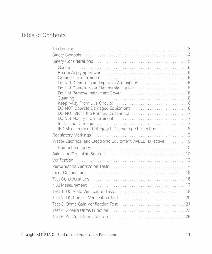
Table of Contents
Trademarks . . . . . . . . . . . . . . . . . . . . . . . . . . . . . . . . . . . . . . . . . . . . . . . .3Safety Symbols . . . . . . . . . . . . . . . . . . . . . . . . . . . . . . . . . . . . . . . . . . . . .4Safety Considerations . . . . . . . . . . . . . . . . . . . . . . . . . . . . . . . . . . . . . . . .5
General . . . . . . . . . . . . . . . . . . . . . . . . . . . . . . . . . . . . . . . . . . . . . . . . .5Before Applying Power . . . . . . . . . . . . . . . . . . . . . . . . . . . . . . . . . . . .5Ground the Instrument . . . . . . . . . . . . . . . . . . . . . . . . . . . . . . . . . . . .5Do Not Operate in an Explosive Atmosphere . . . . . . . . . . . . . . . . . . .5Do Not Operate Near Flammable Liquids . . . . . . . . . . . . . . . . . . . . . .6Do Not Remove Instrument Cover . . . . . . . . . . . . . . . . . . . . . . . . . . .6Cleaning . . . . . . . . . . . . . . . . . . . . . . . . . . . . . . . . . . . . . . . . . . . . . . . .6Keep Away From Live Circuits . . . . . . . . . . . . . . . . . . . . . . . . . . . . . . .6DO NOT Operate Damaged Equipment . . . . . . . . . . . . . . . . . . . . . . .6DO NOT Block the Primary Disconnect . . . . . . . . . . . . . . . . . . . . . . . .7Do Not Modify the Instrument . . . . . . . . . . . . . . . . . . . . . . . . . . . . . . .7In Case of Damage . . . . . . . . . . . . . . . . . . . . . . . . . . . . . . . . . . . . . . . .7IEC Measurement Category II Overvoltage Protection . . . . . . . . . . . .8
Regulatory Markings . . . . . . . . . . . . . . . . . . . . . . . . . . . . . . . . . . . . . . . . .9Waste Electrical and Electronic Equipment (WEEE) Directive . . . . . . .10
Product category: . . . . . . . . . . . . . . . . . . . . . . . . . . . . . . . . . . . . . . .10Sales and Technical Support . . . . . . . . . . . . . . . . . . . . . . . . . . . . . . . . .10Verification . . . . . . . . . . . . . . . . . . . . . . . . . . . . . . . . . . . . . . . . . . . . . . .13Performance Verification Tests . . . . . . . . . . . . . . . . . . . . . . . . . . . . . . . .14Input Connections . . . . . . . . . . . . . . . . . . . . . . . . . . . . . . . . . . . . . . . . . .16Test Considerations . . . . . . . . . . . . . . . . . . . . . . . . . . . . . . . . . . . . . . . .16Null Measurement . . . . . . . . . . . . . . . . . . . . . . . . . . . . . . . . . . . . . . . . .17Test 1: DC Volts Verification Tests . . . . . . . . . . . . . . . . . . . . . . . . . . . . .18Test 2: DC Current Verification Test . . . . . . . . . . . . . . . . . . . . . . . . . . . .20Test 3: Ohms Gain Verification Test . . . . . . . . . . . . . . . . . . . . . . . . . . . .21Test 4: 2-Wire Ohms Function . . . . . . . . . . . . . . . . . . . . . . . . . . . . . . . .23Test 6: AC Volts Verification Test . . . . . . . . . . . . . . . . . . . . . . . . . . . . . .25
Keysight M9181A Calibration and Verification Procedure 11

Test 7: AC Current Verification Test . . . . . . . . . . . . . . . . . . . . . . . . . . . 27Calibration . . . . . . . . . . . . . . . . . . . . . . . . . . . . . . . . . . . . . . . . . . . . . . . 28
Calibration Security . . . . . . . . . . . . . . . . . . . . . . . . . . . . . . . . . . . . . . 28Closed-Case Electronic Calibration . . . . . . . . . . . . . . . . . . . . . . . . . 29Keysight Technologies Calibration Services . . . . . . . . . . . . . . . . . . . 29Calibration Interval . . . . . . . . . . . . . . . . . . . . . . . . . . . . . . . . . . . . . . 29Automating Calibration Procedures . . . . . . . . . . . . . . . . . . . . . . . . . 30Calibration Message and Calibration Count . . . . . . . . . . . . . . . . . . . 30Calibration Process . . . . . . . . . . . . . . . . . . . . . . . . . . . . . . . . . . . . . . 31Calibration Adjustment Process . . . . . . . . . . . . . . . . . . . . . . . . . . . . 32Storing the Calibration Constants . . . . . . . . . . . . . . . . . . . . . . . . . . 33Aborting a Calibration in Progress . . . . . . . . . . . . . . . . . . . . . . . . . . 33Adjustments . . . . . . . . . . . . . . . . . . . . . . . . . . . . . . . . . . . . . . . . . . . . 33Securing the Calibration Memory after Calibration . . . . . . . . . . . . . 34Zero and ADC Adjustment . . . . . . . . . . . . . . . . . . . . . . . . . . . . . . . . 34Calibration Steps . . . . . . . . . . . . . . . . . . . . . . . . . . . . . . . . . . . . . . . . 35Gain Adjustments . . . . . . . . . . . . . . . . . . . . . . . . . . . . . . . . . . . . . . . 36Calibration of ACV Flatness . . . . . . . . . . . . . . . . . . . . . . . . . . . . . . . 38DC Current Offset /Gain Calibration Procedure . . . . . . . . . . . . . . . . 40AC Current Gain and Offset Calibration Procedure . . . . . . . . . . . . . 41Ohms Calibration (2W and 4W) and DCI Source Gain Procedures . 42
12 Keysight M9181A Calibration and Verification Procedure

Verification
Verification
This manual contains procedures for calibrating and verifying the performance of the Keysight M9181A PXI 6½ Digit Multimeter (DMM).
The following table lists the test equipment recommended for calibration and performanceverification. You may substitute calibration standards of equivalent accuracy.
Application Recommended Equipment Accuracy Requirements
DC Voltage Fluke 5720A <1/5 instrument 1 year spec
DC Current Fluke 5720A <1/5 instrument 1 year spec
Resistance Fluke 5720A <1/5 instrument 1 year spec
AC Voltage Fluke 5720A <1/5 instrument 1 year spec
AC Current Fluke 5720A <1/5 instrument 1 year spec
Keysight M9181A Calibration and Verification Procedure 13

Performance Verification Tests
Performance Verification Tests
Use these performance verification tests to verify the measurement performance of the instrument. The performance verification tests use the instrument’s specifications listed in the product data sheet, located at www.keysight.com/find/pxi-dmm.
You can perform three different levels of performance verification tests:
– Self-Test – A series of internal verification tests that give a high confidence that the instrument is operational. Performs an “AutoCalibrate” command.
– Quick Verification – A combination of the internal self–tests and selected verification tests.
– Performance Verification Tests – An extensive set of tests that are recommended as an acceptance test when you first receive the instrument or after performing adjustments.
These three levels of performance verification are described below.
Self–Test
The DMM automatically runs a brief power–on self–test whenever you turn on the instrument. This limited test assures that the instrument is capable of operation, but it does not verify that measurements meet product specifications.
Self-test should be run before beginning calibration or verification. Run the self-test from the Tools menu on the Soft Front Panel (SFP).
– If repair is required, contact a Keysight Service Center.
– If all tests pass, you have a high degree of confidence (~90%) that the instrument is operational.
NOTETo meet the product specifications, perform instrument self-calibration at least once per day. This is a simple software command (AgM918x_AutoCalibrate) that takes less than one minute to perform.
14 Keysight M9181A Calibration and Verification Procedure

Performance Verification Tests
Quick Performance Check
The quick performance check is a combination of internal self–test and an abbreviated performance test (specified by the letter Q in the performance verification tests). This test provides a simple method to achieve high confidence in the instrument’s ability to functionally operate and meet specifications. These tests represent the absolute minimum set of performance checks recommended following any service activity. Auditing the instrument’s performance for the quick check points (designated by a Q) verifies performance for “normal” accuracy drift mechanisms. This test does not check for abnormal component failures.
To perform the quick performance check, do the following:
– Perform a self-test from the Tools menu on the Soft Front Panel.
– Perform the performance verification tests indicated with the letter Q.
If the DMM fails the quick performance check, adjustment or repair is required.
Performance Verification Tests
The performance verification tests are recommended as acceptance tests when you first receive the instrument. The acceptance test results should be compared against the 90 day test limits. You should use the 24–hour test limits only for verification within 24 hours after performing the adjustment procedure. After acceptance, you should repeat the performance verification tests at every calibration interval.
If the instrument fails performance verification, adjustment or repair is required.
Adjustment is recommended at every calibration interval. If adjustment is not made, you must establish a ‘guard band’, using no more than 80% of the specifications, as the verification limits.
Keysight M9181A Calibration and Verification Procedure 15

Input Connections
Input Connections
Shielded, twisted–pair, Teflon interconnect cables of minimum length are recommended between the calibrator and the multimeter. HI and HI Sense should be connected with one twisted pair, and LO and LO Sense should be connected with another. Cable shields should be earth ground referenced. This configuration is recommended for noise reduction and settling time performance during calibration
Test Considerations
Errors may be induced by AC signals present on the input leads during a self–test. Long test leads can also act as an antenna, picking up AC signals.
For optimum performance, all procedures should comply with the following recommendations:
– Ensure that the calibration ambient temperature (Tcal) is stable and between 18 and 28 °C. Ideally the calibration should be performed at 23 °C ±2 °C.
– Ensure ambient relative humidity is less than 80%.
– Allow a 60 minute warmup period with a copper short connected to the voltage input terminals.
– Use shielded twisted pair, Teflon–insulated cables to reduce settling and noise errors. Keep the input cables as short as possible.
– Connect the input cable shields to earth ground. Except where noted in the procedures, connect the calibrator LO source to earth ground at the calibrator. It is important that the LO to earth ground connection be made at only one place in the circuit to avoid ground loops.
– Set the DMM to 32 PLC’s for all verification measurements on functions unless otherwise noted in the verification or calibration process.
Because the instrument is capable of making highly accurate measurements, you must take special care to ensure that the calibration standards and test procedures used do not introduce additional errors. Ideally, the standards used to verify and adjust the instrument should be an order of magnitude more accurate than each instrument range full scale error specification.
16 Keysight M9181A Calibration and Verification Procedure

Null Measurement
Null Measurement
For full accuracy, a null measurement must be performed for the key functions: DC voltage, DC current, and resistance verification measurements. This is done by going to the lowest (most sensitive range) on DCV and OHMS functions and providing a copper short on the input terminals. For the DCI function, the input terminals should be left with no connection.
1 Set the Soft Front Panel to continuous trigger by clicking the Continuous button.
2 Set the Function and Range.
3 Press Null.
The next reading taken by the DMM will become the null value. All subsequent measurements taken on the selected function will have the null value subtracted from the reading.
Keysight M9181A Calibration and Verification Procedure 17

Test 1: DC Volts Verification Tests
Test 1: DC Volts Verification Tests
1 Make sure you have read “Test Considerations” on page 16.
2 Connect the calibrator to the input terminals of the DMM, as shown below.
3 Program a null reading and make all DCV measurement in the following table “nulled” to this measurement. See “Null Measurement”, above.
4 On the M9181A DMM, select each function and range in the order shown in thefollowing table. Using the calibrator, provide the input shown in the same table.
5 Make a DC voltage measurement on the M9181A DMM and return the result. Compare measurement results to the appropriate test limits shown in the table. Be certain to allow for appropriate source settling when using the Fluke 5720A.
18 Keysight M9181A Calibration and Verification Procedure

Test 1: DC Volts Verification Tests
A “Q” in the Quick Check column ind icates a quick performance verification test point. All measurements are taken at 32 NPLC.
CalibratorInput Vol tage
DMM Function DMM Range Quick Check1 Year Error from
Nominal (± V)
0.2 DCV 0.2 Q 2.350E-05
0 DCV 0.2 Q 3.500E-06
–0.2 DCV 0.2 2.350E-05
2 DCV 2 1.900E-04
0 DCV 2 1.000E-05
–2 DCV 2 Q 1.900E-04
20 DCV 20 2.700E-03
0 DCV 20 3.000E-04
–20 DCV 20 2.700E-03
200 DCV 200 Q 2.100E-02
0 DCV 200 1.000E-03
–200 DCV 200 2.100E-02
Keysight M9181A Calibration and Verification Procedure 19

Test 2: DC Current Verification Test
Test 2: DC Current Verification Test
1 Make sure you have read “Test Considerations” on page 16.
2 Remove all connections from the DMM, select DCI function and perform a null measurement. (The input terminals should be left open for the null measurement).
3 Connect the calibrator to the Current input terminals of the DMM, as shown below.
4 On the M9181A DMM, select each function and range in the order shown below. Using the calibrator, provide the input shown in the table below.
5 Make a DC current measurement on the M9181A DMM and return the result. Compare measurement results to the appropriate test limits shown in the table. Be certain to allow for appropriate source settling when using the Fluke 5720A.
CalibratorInput Current (A)
DMM Function DMM Range (A) Quick Check1 Year Error from
Nominal (± A)
0.002 DCI 0.002 2.000E-06
–0.02 DCI 0.02 Q 1.100E-05
0.2 DCI 0.2 1.800E-04
–2 DCI 2 Q 4.100E-03
20 Keysight M9181A Calibration and Verification Procedure

Test 3: Ohms Gain Verification Test
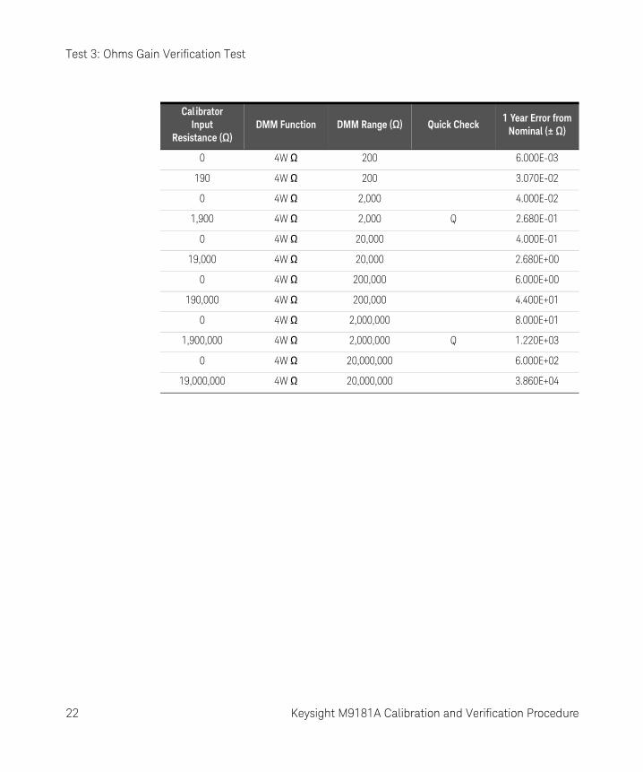
Test 3: Ohms Gain Verification Test
1 Make sure you have read “Test Considerations” on page 16.
2 Set the calibrator to the 4-wire ohms function.
3 Set the M9181A DMM to 4-wire ohms.
4 Connect the calibrator to the input terminals of the DMM, using all four wires as shown below.
5 Perform a null measurement with the calibrator programmed to 0 Ω and the DMM on the lowest range. Perform the 4-wire ohms measurements below on the M9181A DMM “nulled” to this measurement.
6 Select each range in the order shown below. Using the calibrator, provide the resistance value indicated. Compare measurement results to the appropriate test limits shown in the table. Be certain to allow for appropriate source settling.
Keysight M9181A Calibration and Verification Procedure 21
Test 3: Ohms Gain Verification Test
CalibratorInput
Resistance (W)DMM Function DMM Range (W) Quick Check
1 Year Error fromNominal (± W)
0 4W W 200 6.000E-03
190 4W W 200 3.070E-02
0 4W W 2,000 4.000E-02
1,900 4W W 2,000 Q 2.680E-01
0 4W W 20,000 4.000E-01
19,000 4W W 20,000 2.680E+00
0 4W W 200,000 6.000E+00
190,000 4W W 200,000 4.400E+01
0 4W W 2,000,000 8.000E+01
1,900,000 4W W 2,000,000 Q 1.220E+03
0 4W W 20,000,000 6.000E+02
19,000,000 4W W 20,000,000 3.860E+04
22 Keysight M9181A Calibration and Verification Procedure

Test 4: 2-Wire Ohms Function
Test 4: 2-Wire Ohms Function
1 Make sure you have read “Test Considerations” on page 16.
2 Set the M9181A DMM to 2-wire ohms function.
3 Connect the calibrator to the input terminals of the DMM, as shown below.
4 On the calibrator, select 2-wire compensation
5 Perform a null measurement with 0 Ω from the calibrator. All 2-wire ohms measurements are now made relative to this null to remove the lead resistance.
6 Select each range in the order shown below. Using the calibrator, provide the resistance value indicated. Compare measurement results to the appropriate test limits shown in the table. Be certain to allow for appropriate source settling.
Keysight M9181A Calibration and Verification Procedure 23

Test 4: 2-Wire Ohms Function
Calibrator Input Resistance (W)
DMM Function DMM Range (W) Quick Check1 Year Error from
Nominal (± W)
190 2W W 200 3.070E-02
1,900 2W W 2,000 2.680E-01
19,000 2W W 20,000 Q 2.680E+00
190,000 2W W 200,000 4.400E+01
1,900,000 2W W 2,000,000 1.220E+03
19,000,000 2W W 20,000,000 3.860E+04
24 Keysight M9181A Calibration and Verification Procedure

Test 6: AC Volts Verification Test
Test 6: AC Volts Verification Test
1 Make sure you have read “Test Considerations” on page 16.
2 Connect the calibrator to the input terminals of the DMM, as shown below.
3 Compare AC voltage measurement results from the M9181A DMM to the appropriate test limits shown in the table. Be certain to allow for appropriate source settling.
Keysight M9181A Calibration and Verification Procedure 25

Test 6: AC Volts Verification Test
Calib. SourceInput Vol tage
(VAC)
Calib. SourceFreq (Hz)
DMM Function
DMM Vol tage Range
Quick Check1 Year Error
from Nominal (± V)
0.02 47 ACV 0.2 7.320E-04
0.02 50000 ACV 0.2 1.440E-03
0.2 47 ACV 0.2 Q 1.020E-03
0.1 20 ACV 2 2.200E-03
2 47 ACV 2 2.800E-03
2 10000 ACV 2 2.800E-03
0.1 50000 ACV 2 2.900E-03
2 100000 ACV 2 4.900E-02
20 10000 ACV 20 4.000E-02
20 50000 ACV 20 Q 9.500E-02
200 47 ACV 200 4.100E-01
160 50000 ACV 200 1.230E+00
26 Keysight M9181A Calibration and Verification Procedure

Test 7: AC Current Verification Test
Test 7: AC Current Verification Test
1 Make sure you have read “Test Considerations” on page 16.
2 Connect the calibrator to the input terminals of the DMM, as shown below.
3 Set the AC Current function on the M9181A DMM.
4 Select each range in the order shown below. Using the calibrator, provide the input current and frequency indicated. Compare AC current measurement results from the M9181A DMM to the appropriate test limits shown in the table. Be certain to allow for appropriate source settling.
CalibratorInput ACI
Cal ib.Freq. (Hz)
DMM Function
DMM Range (A)
Quick Check1 Year Error
from Nominal (± A)
2.30E-03 10 ACI 0.002 7.070E-05
2.30E-03 20 ACI 0.002 2.700E-05
2.00E-04 47 ACI 0.002 Q 4.240E-06
2.30E-03 1000 ACI 0.002 6.760E-06
2.00E-04 10000 ACI 0.002 4.440E-06
2.00E-02 47 ACI 0.02 6.200E-05
2.00E-01 1000 ACI 0.2 Q 6.200E-04
2.00E+00 1000 ACI 2 1.100E-02
Keysight M9181A Calibration and Verification Procedure 27

Calibration
Calibration
From the Soft Front Panel (SFP), you can read the calibration count, secure and unsecure the calibration memory, read and edit the calibration message and perform each step of the calibration process. From the SFP, click the Single button to place the product in single trigger mode, and then select Tools, Calibration. This will open a window that shows you the calibration message and calibration count. It also gives you access to the tools that perform calibration.
The first step is to unsecure the calibration memory. This is necessary in order to store a new calibration message and to change the DMM’s calibration values.
Calibration Security
The M9181A DMMs have a security code that is stored in non-volatile memory. This feature allows you to prevent accidental or unauthorized adjustments of the instrument. Before you can adjust the instrument, you must unsecure it by entering the correct security code.
When you first receive your instrument, it is secured with the factory default security code of AGM918X. It is a good practice to change the security code to a new value when you receive your instrument. The security code must start with a letter and may contain any combination of up to 12 letters, numbers, or underscores ( _ ). If you change the security code from its default value, be sure to record the new code in a secure location in order to use it the next time you do calibration. If you lose your new code, you will need to contact Keysight support to receive a temporary security code based on the product’s serial number.
To unsecure the instrument for calibration, enter the security code.
Press Unlock. The CAL UNSECURED message appears.
To unsecure or secure the instrument under program control, see the documentation on the Calibrate.SecurityEnable method in the IVI driver documentation.
28 Keysight M9181A Calibration and Verification Procedure

Calibration
Closed-Case Electronic Calibration
The instrument features closed-case electronic calibration. No internal mechanical adjustments are required. The instrument calculates correction factors based upon the input reference values that you enter. The new correction factors are stored in non-volatile memory until the next calibration adjustment is performed.
Keysight Technologies Calibration Services
Keysight Technologies offers calibration services at competitive prices. When your instrument is due for calibration, contact your local Keysight Service Center for recalibration.
Calibration Interval
The instrument should be calibrated on a regular interval determined by the measurement accuracy requirements of your application. A one-year interval is adequate for most applications. Accuracy specifications will remain valid only if adjustment is made at regular calibration intervals. Accuracy specifications are not valid beyond the one-year calibration interval. Keysight does not recommend extending calibration intervals beyond two years for any application.
Adjustment is Recommended
Specifications are only valid within the period stated from the last adjustment. Keysight recommends that complete re-adjustment always be performed at the selected calibration interval. This is necessary to ensure that the instrument will remain within specification for the next calibration interval and provides the best long-term stability.
Performance data measured during performance verification tests do not mean that the instrument will remain within these limits unless the adjustments are performed. Use the Calibration Count feature to verify that adjustments have been performed and stored in non-volatile memory. This can be done using the SFP or with computer control.
In the SFP, click Single, then choose Calibration from the Tools menu. You can then read the calibration count and the calibration message. To do this programmatically, use the AGM918X_ATTR_CALIBRATE_COUNT method.
Keysight M9181A Calibration and Verification Procedure 29

Calibration
Time Required for Calibration
The instrument can be automatically calibrated under computer control. With computer control you can perform the complete calibration procedure and performance verification tests in approximately 60 minutes once the instrument is warmed up (see “Test Considerations” on page 16).
Automating Calibration Procedures
These adjustment procedures demonstrate adjustment through the Soft Front Panel. You can automate the complete verification and adjustment procedures outlined in this manual by programming instrument configurations and tests over the remote interface. You can then read back verification data and compare the results to the appropriate test limit values.
Calibration Message and Calibration Count
The instrument allows you to store a message in calibration memory. For example, you can store information such as the date the last calibration was performed, the date the next calibration is due, the instrument’s serial number, or even the name and phone number of the person to contact for calibration. The calibration message may contain up to 40 characters.
You can record a calibration message only when the instrument is unsecured. You can read the calibration message whether the instrument is secured or unsecured.
You can read the calibration message from the Tools menu of the SFP. If the DMM is unsecured, you can enter a new calibration message in the Calibration Message box.
To do this remotely, use the AGM918X_ATTR_CALIBRATE_MESSAGE method.
Calibration Count
You can query the instrument to determine how many calibrations have been performed.
NOTEYour instrument was calibrated before it left the factory. When you receive your instrument, be sure to read the count to determine its initial value. By monitoring the calibration count you can read the number of times the calibration data has been written into the DMM’s non-volatile memory.
30 Keysight M9181A Calibration and Verification Procedure

Calibration
The calibration count increments up to a maximum of 232 (over 4 billion) after which it rolls over to 0. The value increments by one for each time the calibration points are store to non volatile memory. Therefore, a complete calibration may increase the value by many counts.
You can see the calibration count from the Tools menu in the SFP. To do this remotely, use the method AGM918X_ATTR_CALIBRATE_COUNT.
Calibration Process
The following general procedure is the recommended method to complete a full instrument calibration. The initial verification tests may be skipped if initial data is not required.
1 Read “Test Considerations” on page 16.
2 Perform the verification tests to characterize the instrument.
3 Unsecure the instrument for calibration (“Calibration Security” on page 28).
4 Perform the adjustment procedures.
5 Store the calibration constants in the calibration memory.
6 Secure the instrument’s calibration memory to prevent accidental or unauthorized adjustments.
7 Document the new security code and calibration count in the instrument’s maintenance records.
All adjustments are made using the SFP or the remote interface. Commands used to perform the adjustments are listed in Calibration section of the programmer’s guide. In addition, the SFP’s call monitor log allows you to see each calibration message sent to the DMM.
Keysight M9181A Calibration and Verification Procedure 31

Calibration
Calibration Adjustment Process
The following three steps comprise the general process for calibration adjustment of the DMM.
1 Select the calibration ad justment step.
Calibration is done by performing each of the calibration steps. Each step can be selected using the “setup step #” pulldown tab in the SFP. For remote programming, use the AGM918X_ATTR_CALIBRATE_SETUP to declare the test step to be performed. Setting this calibration step reconfigures the DMM in preparation for the specified calibration step number.
2 Apply the source.
Apply the source to the DMM and program the source to provide the function, amplitude (and frequency) indicated with each step shown below.
3 Enter ad justment values.
The calibration can be performed without the exact amplitude of the signal sourced to the DMM. One can measure the exact value and enter this value. From the Soft Front Panel, simply type in the calibrate value and then press the “perform calibration” button. To enter a calibration value from the remote interface use the AgM918x Calibrate.Value property to enter the value followed by a value where the value is a known value of the input attached to the DMM and then execute the AgM918x_CalibratePerformCalibration function. The calibration value is the actual value being supplied to the instrument. This typically is within 10% of the nominal value required to calibrate a specific step. This allows for the calibration to be made with less accurate standard sources and bootstrapped up to accuracy a precision multimeter such as a Keysight 3458A. The SFP returns “Cal Successful” when each calibration step has been completed. Press “Close” to continue to the next calibration step
Repeat steps 1 through 3 above to perform calibration on all the calibration steps.
32 Keysight M9181A Calibration and Verification Procedure

Calibration
Storing the Calibration Constants
To store the calibration values in non-volatile calibration memory from the remote interface, use the AgM918x_CalibrateStoreCalibrationConstants function. From the SFP, press “Store Calibration Constant.” This measured calibration constant, along with the Calibration Message, is stored in non-volatile memory of the DMM and from the SFP you will see the calibration count increment by one. (From the remote interface you can read the calibration count if you desire).
Aborting a Calibration in Progress
Sometimes it may be necessary to abort a calibration after the procedure has already been initiated. You can abort a calibration at any time on any module by turning off the power or closing the calibration window on the Soft Front Panel or closing the device.
Adjustments
You will need a test input cable and connectors set and a low thermal input short to adjust the instrument (see “Input Connections” on page 16).
Calibration adjustments
Each calibration step number must be executed to perform a complete calibration of the product. (Refer to the Calibration Chart) for the various calibration steps.
Calibration Step dependencies are indicated when certain calibration steps must be performed before another step can be performed.
Unless otherwise indicated, set the aperture of the DMM to 0.5 sec for all calibration steps.
NOTEYou do not need to store calibration constants after every calibration step, but you must store them before leaving the calibration process. If this is not done and you leave the calibration process; all performed calibration steps will be lost as they will not be stored in the nonvolatile calibration memory.
Keysight M9181A Calibration and Verification Procedure 33

Calibration
Securing the Calibration Memory after Calibration
Set the AgM918x_CalibrateSecurityEnable function to true to complete the calibration process by securing the calibration. This can also be done using the SFP.
Zero and ADC Adjustment
Adjustment Procedure
Be sure to allow the instrument to warm up and stabilize for 90 minutes before performing the adjustments.
Each time you perform a zero adjustment, the instrument stores a new set of offset correction constants for every measurement function and range. The instrument will sequence through all required functions and ranges automatically and store new zero offset calibration constants. All offset corrections are determined automatically. You may not correct a single range or function without re-entering ALL zero offset correction constants automatically. This feature is intended to save calibration time and improve zero calibration consistency.
NOTERemember that if you change the security code on the product here, you MUST write this down as it will be required to be entered the next time you CALIBRATE the product.
NOTENever turn off the DMM or abort calibration while performing a calibration step. This may cause calibration memory for the present function to be lost.
34 Keysight M9181A Calibration and Verification Procedure

Calibration
Calibration Steps
Calibrate Zeros (Calibration Step 1)
This step performs calibration on the “zero” measurement for the offset calibration of DCV, 2WΩ, and 4WΩ.
This procedure uses a low-thermal shorting block across the input connectors.
1 Install the shorting block on the front panel voltage input terminals of the DMM, as shown below.
2 Now Perform the calibration process (see “Calibration Process” on page 31). Enter the calibration value of 0.00 for the calibration value (because the source is 0 V).
SFP Cal Step Calibration Name Input Value VDC
1 Zeros 0.00 Low Thermal Short
Keysight M9181A Calibration and Verification Procedure 35

Calibration
ADC Linearity Adjustment (Calibration steps 2-6)
1 Perform the calibration process in the SFP: select the Step #, set the source, enter the Calibrate Value, and click Store Calibration Constant.
2 Enter the calibration value for each of the calibration steps if the sourced input is not exact.
Gain Adjustments
The instrument calculates and stores gain corrections for each input value. The gain constant is computed from the calibration value entered for the calibration command and from measurements made automatically during the adjustment procedure.
Most measuring functions and ranges have gain adjustment procedures, as shown in the tables below. No calibration is required for capacitance, as it uses the calibrated current sources in the ohms functions. Adjustments for each function should be performed ONLY in the order shown.
NOTESteps 2-6 must be done in order.
SFP Cal Step Calibration Name Input Value VDC
2 ADC Linearity 1.16 1.16
3 ADC Linearity 1.9 1.9
4 ADC Linearity 0.6 0.6
5 ADC Linearity –1.1 –1.1
6 ADC Linearity –2.3 –2.3
36 Keysight M9181A Calibration and Verification Procedure
Calibration
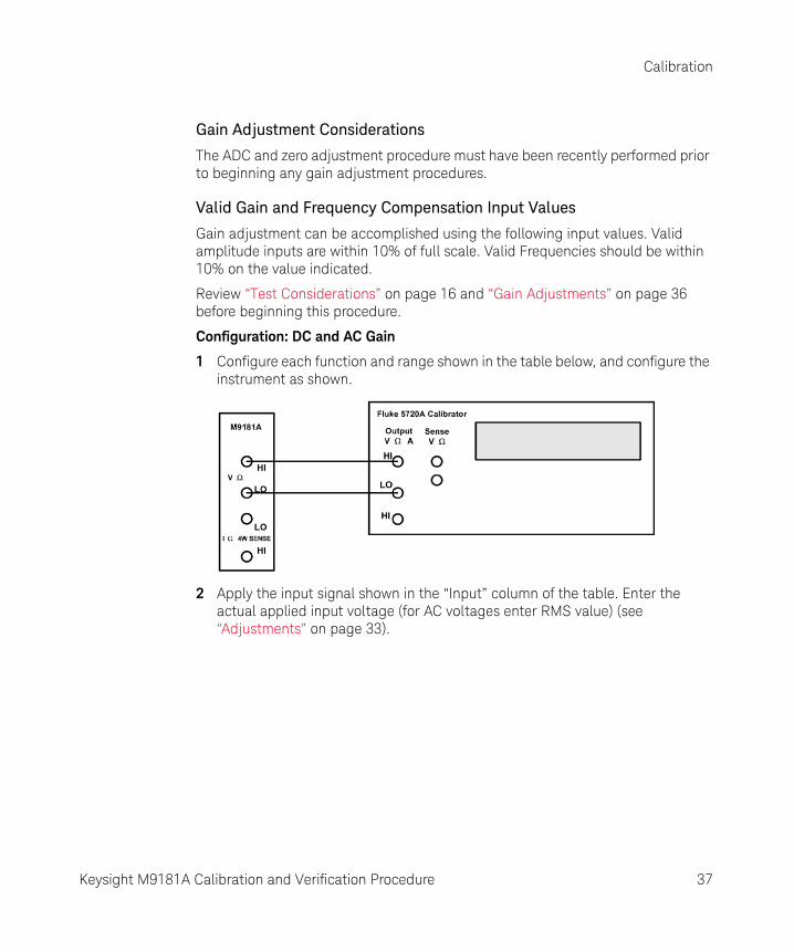
Gain Adjustment Considerations
The ADC and zero adjustment procedure must have been recently performed prior to beginning any gain adjustment procedures.
Valid Gain and Frequency Compensation Input Values
Gain adjustment can be accomplished using the following input values. Valid amplitude inputs are within 10% of full scale. Valid Frequencies should be within 10% on the value indicated.
Review “Test Considerations” on page 16 and “Gain Adjustments” on page 36 before beginning this procedure.
Configuration: DC and AC Gain
1 Configure each function and range shown in the table below, and configure the instrument as shown.
2 Apply the input signal shown in the “Input” column of the table. Enter the actual applied input voltage (for AC voltages enter RMS value) (see “Adjustments” on page 33).
Keysight M9181A Calibration and Verification Procedure 37

Calibration
3 Perform the calibration process in the SFP: select the Step #, set the source, enter the Calibrate Value, and click Store Calibration Constant.
Repeat steps 1 through 3 for each gain adjustment point shown in the table above.
SFP Cal Step Step NameCalibrator Input
Freq (Hz)Cal ibrator Input
Amplitude, Function
7 DCV Gain 0.2 V 0.2 VDC
8 DCV Gain 2 V 2 VDC
9 DCV Gain 20 V 20 VDC
10 DCV Gain 200 V 200 VDC
11 (Skip for M9181A - Applies only to M9182A/83A)
12 ACV Gain 0.2 Vrms 1000 0.2 VAC
13 ACV Gain 2 Vrms 1000 2 VAC
14 ACV Gain 20 Vrms 1000 20 VAC
15 ACV Gain 200 Vrms 1000 200 VAC
16 (Skip for M9181A - Applies only to M9182A/83A)
38 Keysight M9181A Calibration and Verification Procedure

Calibration
Calibration of ACV Flatness
Review “Test Considerations” on page 16 and “Gain Adjustments” on page 36 before beginning this procedure.
Configuration: AC Flatness
1 Configure each function and range shown in the table below.
2 Apply the input signal shown in the “Input” column of the table. Enter the actual applied rms input voltage (see “Adjustments” on page 33).
The next calibration steps perform flatness calibration at 50 kHz on each of the ranges in the ACV. Turn ACV fast off by selecting slow filtering using the SFP. Perform the following steps using the “calibration process” described.
3 Perform the calibration process in the SFP: select the Step #, set the source, enter the Calibrate Value, and click Store Calibration Constant.
Repeat steps 1 through 3 for each gain adjustment point shown in the above table.
NOTEBefore calibrating the flatness on a specific range, calibrate Gain on that range. (For example step 17 can be performed only after step 12 is performed).
SFP Cal Step Step NameCalibrator Input
Freq (Hz)Calibrator Input
Amplitude, Function
17 ACV FComp .2 V 50000 0.2 VAC
18 ACV FComp 2 V 50000 2 VAC
19 ACV FComp 20 V 50000 20 VAC
20 ACV FComp 200/300 V 50000 160 VAC
Keysight M9181A Calibration and Verification Procedure 39

Calibration
Calibration of ACV “zeroes”
Because of the nature of the RMS conversion process, these points are NOT done at 0 V but at the amplitude and frequency level indicated. Review “Test Considerations” on page 16 and “Gain Adjustments” on page 36 before beginning this procedure.
Configuration: AC Offset
1 Configure each function and range shown in the table below.
2 Apply the input signal shown in the “Input” column of the table. Enter the actual applied rms input voltage (see “Adjustments” on page 33).
3 Perform the calibration process in the SFP: select the Step #, set the source, enter the Calibrate Value, and click Store Calibration Constant.
NOTEBefore the ACV offset calibration step can be performed on a given range, the ACV gain and flatness must be performed first. For example, you must perform steps 12 and 17 before step 21.
SFP Cal Step Step NameCalibrator Input
Freq (Hz)Cal ibrator Input
Amplitude, Function
21 ACV Offset 0.2 V 1000 0.02 VAC
22 ACV Offset 2 V 1000 0.1 VAC
23 ACV Offset 20 V 1000 1 VAC
24 ACV Offset 200/300 V 1000 10 VAC
40 Keysight M9181A Calibration and Verification Procedure

Calibration
DC Current Offset /Gain Calibration Procedure
Review “Test Considerations” on page 16 and “Gain Adjustments” on page 36 before beginning this procedure.
Configuration: DC Current
1 For steps 30 through 34 in the table below, configure each function and range as shown, and configure the instrument as shown below.
2 Apply the input signal shown in the “Input” column of the table. Enter the actual applied rms input voltage (see “Adjustments” on page 33).
NOTESteps 27-30 are only available with the M9183A. If you are calibrating an M9182A, skip these steps. Always complete tests in the specified order as shown in the appropriate table.
Before step 26 can be performed, the offsets (step 1) and VDC gains (steps 7, 8, and 9) must be performed. Step 26 must be performed before steps 27-34.
Keysight M9181A Calibration and Verification Procedure 41

Calibration
AC Current Gain and Offset Calibration Procedure
Review “Test Considerations” on page 16 and “Gain Adjustments” on page 36 before beginning this procedure.
1 Configure each function and range shown in the table below.
2 Apply the input signal shown in the “Input” column of the table. Enter the actual applied rms input voltage (see “Adjustments” on page 33).
SFP Cal Step Step Name Calibrator Input Amplitude, Function
26 DCI Offset Open
27 (Skip for M9181A - Applies only to M9182A/83A)
28 (Skip for M9181A - Applies only to M9182A/83A)
29 (Skip for M9181A - Applies only to M9182A/83A)
30 (Skip for M9181A - Applies only to M9182A/83A)
31 DCI Gain .002 A 0.002 IDC
32 DCI Gain .02 A 0.02 IDC
33 DCI Gain .2 A 0.2 IDC
34 DCI Gain 2 A 2 IDC
NOTEThe Fluke 5720A calibrator does not have the capability to source the currents for calibration steps 27, 28, and 29. Source these currents by performing the following steps. All other calibration steps are sourced using the Fluke 5720A and its DCI output with the current shown in the Input section above.
NOTEBefore the ACI Offset on a given range can be performed, the ACI gain on that range must be performed (for example, you must perform step 35 before step 39).
42 Keysight M9181A Calibration and Verification Procedure
Calibration
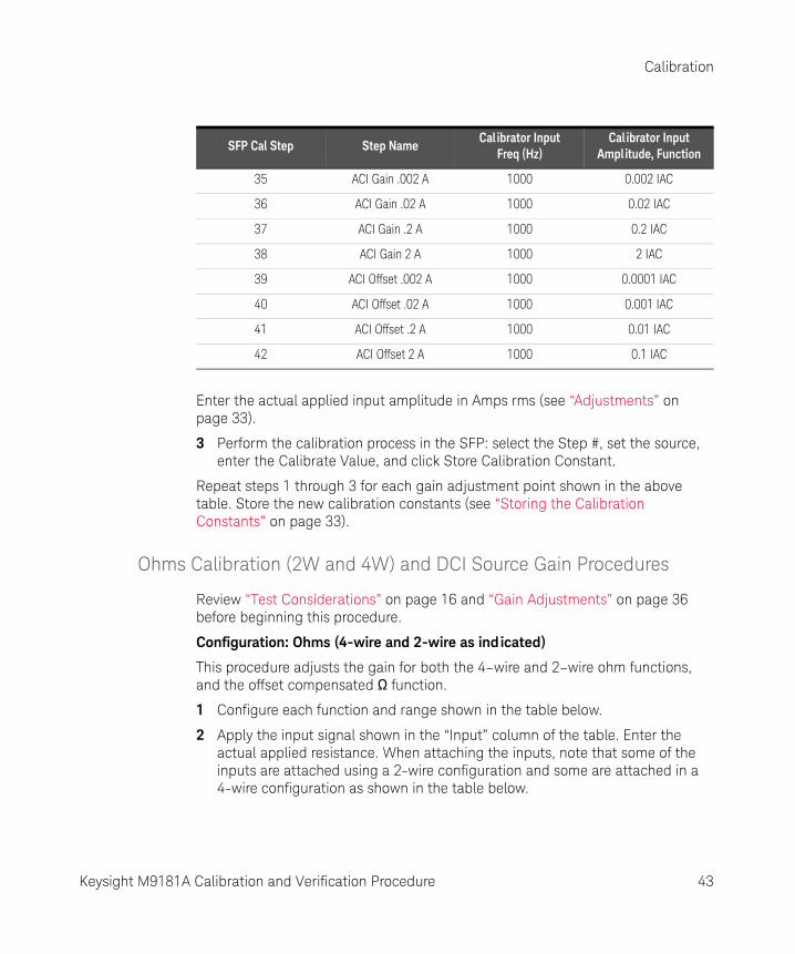
Enter the actual applied input amplitude in Amps rms (see “Adjustments” on page 33).
3 Perform the calibration process in the SFP: select the Step #, set the source, enter the Calibrate Value, and click Store Calibration Constant.
Repeat steps 1 through 3 for each gain adjustment point shown in the above table. Store the new calibration constants (see “Storing the Calibration Constants” on page 33).
Ohms Calibration (2W and 4W) and DCI Source Gain Procedures
Review “Test Considerations” on page 16 and “Gain Adjustments” on page 36 before beginning this procedure.
Configuration: Ohms (4-wire and 2-wire as ind icated)
This procedure adjusts the gain for both the 4–wire and 2–wire ohm functions, and the offset compensated Ω function.
1 Configure each function and range shown in the table below.
2 Apply the input signal shown in the “Input” column of the table. Enter the actual applied resistance. When attaching the inputs, note that some of the inputs are attached using a 2-wire configuration and some are attached in a 4-wire configuration as shown in the table below.
SFP Cal Step Step NameCalibrator Input
Freq (Hz)Calibrator Input
Amplitude, Function
35 ACI Gain .002 A 1000 0.002 IAC
36 ACI Gain .02 A 1000 0.02 IAC
37 ACI Gain .2 A 1000 0.2 IAC
38 ACI Gain 2 A 1000 2 IAC
39 ACI Offset .002 A 1000 0.0001 IAC
40 ACI Offset .02 A 1000 0.001 IAC
41 ACI Offset .2 A 1000 0.01 IAC
42 ACI Offset 2 A 1000 0.1 IAC
Keysight M9181A Calibration and Verification Procedure 43

Calibration
3 Configure the instrument as shown below, depending on whether the calibration step is 2-wire or 4-wire.
4 Enter the actual applied input resistance (see “Adjustments” on page 33).
a Successful completion of each adjustment value is indicated by the message CAL SUCCEEDED flashing in the display.
b If a problem is encountered, the display will flash the message CAL FAILED. Check the input value, range, function, and entered adjustment value to correct the problem and repeat the adjustment step.
5 Repeat these steps for each gain adjustment point shown in the table.
6 Store the new calibration constants (see “Storing the Calibration Constants” on page 33).
NOTEBefore steps 44-48 can be performed, DCV gains (steps 7-11) must be performed.
44 Keysight M9181A Calibration and Verification Procedure

Calibration
SFP Cal Step Function Range (W) Input Level Input Function 2W/4W W
43 (Skip for M9181A - Applies only to M9182A/83A)
44 Ohm-4W Gain 20 Ω 4W 19
45 Ohm-4W Gain 200 Ω 4W 190
46 Ohm-4W Gain 2,000 Ω 4W 1,900
47 Ohm-4W Gain 20,000 Ω 4W 19,000
48 Ohm-4W Gain 200,000 Ω 4W 190,000
49 Ohm-4W Gain 2,000,000 Ω 4W 1,900,000
50 Ohm-4W Gain 20,000,000 Ω 4W 19,000,000
51 (Skip for M9181A - Applies only to M9182A/83A)
52 (Skip for M9181A - Applies only to M9182A/83A)
Keysight M9181A Calibration and Verification Procedure 45

Calibration
THIS PAGE HAS BEEN INTENTIONALLY LEFT BLANK.
46 Keysight M9181A Calibration and Verification Procedure

This information is subject to change without notice. Always refer to the Keysight website for the latest revision.
© Keysight Technologies 2011 - 2017 Edition 3, November 1, 2017
Printed in Malaysia
*5185-9181*5185-9181 www.keysight.com