agilent 34410a/11a 6 ½ digit multimeter · product name: 6 ½ digit multimeter model number:...
TRANSCRIPT
Agilent 34410A/11A 6 ½ Digit Multimeter(includes the L4411A 1U DMM)
User’s Guide
Agilent Technologies
Notices© Agilent Technologies, Inc. 2005, 2006, 2007
No part of this manual may be reproduced in any form or by any means (including elec-tronic storage and retrieval or translation into a foreign language) without prior agree-ment and written consent from Agilent Technologies, Inc. as governed by United States and international copyright laws.
Manual Part Number34410-90001
Edition
Fourth Edition. February 2007
Printed in Malaysia
Agilent Technologies, Inc.3501 Stevens Creek Blvd.Santa Clara, CA 95052 USA
Microsoft® and Windows® are U.S. regis-tered trademarks of Microsoft Corporation.
Software RevisionThis guide is valid for the firmware that was installed in the instrument at the time of manufacture. However, upgrading the firm-ware may add or change product features. For the latest firmware and documentation, go to the product page at:
www.agilent.com/find/34410A
or
www.agilent.com/find/34411A
or
www.agilent.com/find/L4411A
Warranty
The material contained in this docu-ment is provided “as is,” and is sub-ject to being changed, without notice, in future editions. Further, to the max-imum extent permitted by applicable law, Agilent disclaims all warranties, either express or implied, with regard to this manual and any information contained herein, including but not limited to the implied warranties of merchantability and fitness for a par-ticular purpose. Agilent shall not be liable for errors or for incidental or consequential damages in connec-tion with the furnishing, use, or per-formance of this document or of any information contained herein. Should Agilent and the user have a separate written agreement with warranty terms covering the material in this document that conflict with these terms, the warranty terms in the sep-arate agreement shall control.
Technology Licenses The hardware and/or software described in this document are furnished under a license and may be used or copied only in accor-dance with the terms of such license.
Restricted Rights Legend
U.S. Government Restricted Rights. Soft-ware and technical data rights granted to the federal government include only those rights customarily provided to end user cus-tomers. Agilent provides this customary commercial license in Software and techni-cal data pursuant to FAR 12.211 (Technical Data) and 12.212 (Computer Software) and, for the Department of Defense, DFARS 252.227-7015 (Technical Data - Commercial Items) and DFARS 227.7202-3 (Rights in Commercial Computer Software or Com-puter Software Documentation).
Safety Notices
CAUTION
A CAUTION notice denotes a haz-ard. It calls attention to an operat-ing procedure, practice, or the like that, if not correctly performed or adhered to, could result in damage to the product or loss of important data. Do not proceed beyond a CAUTION notice until the indicated conditions are fully understood and met.
WARNING
A WARNING notice denotes a hazard. It calls attention to an operating procedure, practice, or the like that, if not correctly per-formed or adhered to, could result in personal injury or death. Do not proceed beyond a WARNING notice until the indicated condi-tions are fully understood and met.
2 34410A/11A/L4411A User’s Guide
Safety InformationDo not defeat power cord safety ground fea-ture. Plug in to a grounded (earthed) outlet.
Do not use product in any manner not speci-fied by the manufacturer.
Do not install substitute parts or perform any unauthorized modification to the prod-uct. Return the product to an Agilent Tech-nologies Sales and Service Office for service and repair to ensure that safety features are maintained.
Safety Symbols
WARNING
Main Power and Test Input Dis-connect: Unplug instrument from wall outlet, remove power cord, and remove all probes from all terminals before servicing. Only qualified, service-trained person-nel should remove the cover from the instrument.
WARNING
Line and Current Protection Fuses: For continued protection against fire, replace the line fuse and the current-protection fuse only with fuses of the specified type and rating.
WARNING
Front/Rear Switch: Do not change the position of the Front/Rear switch on the front panel while signals are present on either the front or rear set of ter-minals. The switch is not intended as an active multiplexer. Switch-ing while high voltages or cur-rents are present may cause instrument damage and lead to the risk of electric shock.
WARNING
IEC Measurement Category II. The HI and LO input terminals may be connected to mains in IEC Cate-gory II installations for line volt-ages up to 300 VAC. To avoid the danger of electric shock, do not connect the inputs to mains for line voltages above 300 VAC. See "IEC Measurement Category II Overvoltage Protection" on the following page for further infor-mation.
WARNING
Protection Limits: To avoid instru-ment damage and the risk of elec-tric shock, do not exceed any of the Protection Limits defined in the following section.
Earth Ground
Chassis Ground
Risk of electric shock
Refer to manual for addi-tional safety information
CAT II (300V) IEC Measurement Category II. Inputs may be connected to mains (up to 300 VAC) under Category II overvoltage condi-tions.
34410A/11A/L4411A User’s Guide 3
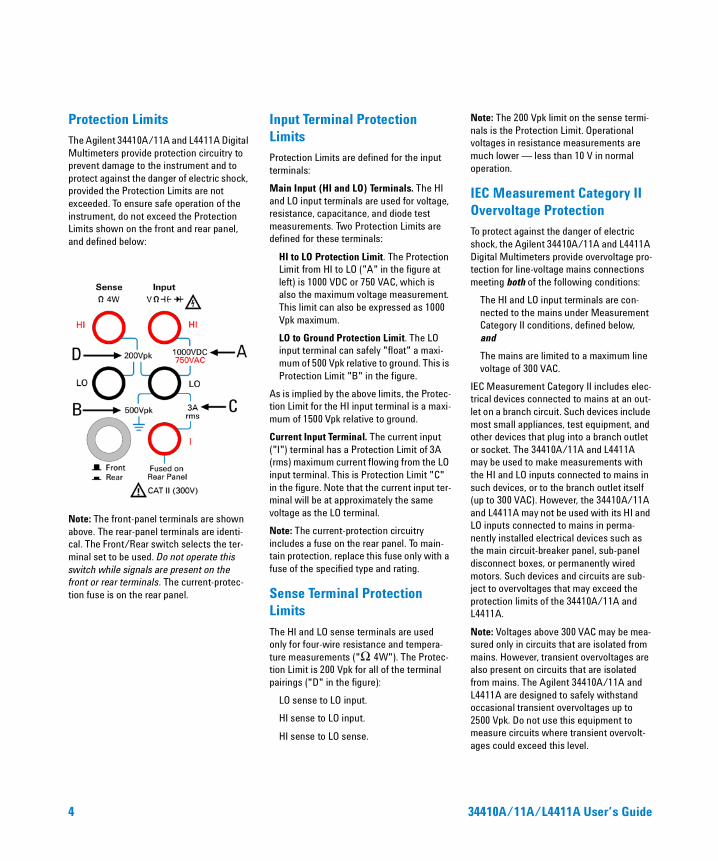
Protection LimitsThe Agilent 34410A/11A and L4411A Digital Multimeters provide protection circuitry to prevent damage to the instrument and to protect against the danger of electric shock, provided the Protection Limits are not exceeded. To ensure safe operation of the instrument, do not exceed the Protection Limits shown on the front and rear panel, and defined below:
Note: The front-panel terminals are shown above. The rear-panel terminals are identi-cal. The Front/Rear switch selects the ter-minal set to be used. Do not operate this switch while signals are present on the front or rear terminals. The current-protec-tion fuse is on the rear panel.
Input Terminal Protection LimitsProtection Limits are defined for the input terminals:
Main Input (HI and LO) Terminals. The HI and LO input terminals are used for voltage, resistance, capacitance, and diode test measurements. Two Protection Limits are defined for these terminals:
HI to LO Protection Limit. The Protection Limit from HI to LO ("A" in the figure at left) is 1000 VDC or 750 VAC, which is also the maximum voltage measurement. This limit can also be expressed as 1000 Vpk maximum.
LO to Ground Protection Limit. The LO input terminal can safely "float" a maxi-mum of 500 Vpk relative to ground. This is Protection Limit "B" in the figure.
As is implied by the above limits, the Protec-tion Limit for the HI input terminal is a maxi-mum of 1500 Vpk relative to ground.
Current Input Terminal. The current input ("I") terminal has a Protection Limit of 3A (rms) maximum current flowing from the LO input terminal. This is Protection Limit "C" in the figure. Note that the current input ter-minal will be at approximately the same voltage as the LO terminal.
Note: The current-protection circuitry includes a fuse on the rear panel. To main-tain protection, replace this fuse only with a fuse of the specified type and rating.
Sense Terminal Protection Limits
The HI and LO sense terminals are used only for four-wire resistance and tempera-ture measurements ("Ω 4W"). The Protec-tion Limit is 200 Vpk for all of the terminal pairings ("D" in the figure):
LO sense to LO input.
HI sense to LO input.
HI sense to LO sense.
Note: The 200 Vpk limit on the sense termi-nals is the Protection Limit. Operational voltages in resistance measurements are much lower — less than 10 V in normal operation.
IEC Measurement Category II Overvoltage ProtectionTo protect against the danger of electric shock, the Agilent 34410A/11A and L4411A Digital Multimeters provide overvoltage pro-tection for line-voltage mains connections meeting both of the following conditions:
The HI and LO input terminals are con-nected to the mains under Measurement Category II conditions, defined below, and
The mains are limited to a maximum line voltage of 300 VAC.
IEC Measurement Category II includes elec-trical devices connected to mains at an out-let on a branch circuit. Such devices include most small appliances, test equipment, and other devices that plug into a branch outlet or socket. The 34410A/11A and L4411A may be used to make measurements with the HI and LO inputs connected to mains in such devices, or to the branch outlet itself (up to 300 VAC). However, the 34410A/11A and L4411A may not be used with its HI and LO inputs connected to mains in perma-nently installed electrical devices such as the main circuit-breaker panel, sub-panel disconnect boxes, or permanently wired motors. Such devices and circuits are sub-ject to overvoltages that may exceed the protection limits of the 34410A/11A and L4411A.
Note: Voltages above 300 VAC may be mea-sured only in circuits that are isolated from mains. However, transient overvoltages are also present on circuits that are isolated from mains. The Agilent 34410A/11A and L4411A are designed to safely withstand occasional transient overvoltages up to 2500 Vpk. Do not use this equipment to measure circuits where transient overvolt-ages could exceed this level.
4 34410A/11A/L4411A User’s Guide
Additional Notices
Waste Electrical and Electronic Equipment (WEEE) Directive 2002/96/EC
This product complies with the WEEE Direc-tive (2002/96/EC) marking requirement. The affixed product label (see below) indi-cates that you must not discard this electri-cal/electronic product in domestic household waste.
Product Category: With reference to the equipment types in the WEEE directive Annex 1, this product is classified as a "Monitoring and Control instrumentation" product.
Do not dispose in domestic household waste.
To return unwanted products, contact your local Agilent office, or see www.agilent.com/environment/product for more information.
Agilent 34138A Test Lead Set
The Agilent 34410A/11A is provided with an Agilent 34138A Test Lead Set, described below.
Test Lead Ratings
Test Leads - 1000V, 15A
Fine Tip Probe Attachments - 300V, 3A
Mini Grabber Attachment - 300V, 3A
SMT Grabber Attachments - 300V, 3A
Operation
The Fine Tip, Mini Grabber, and SMT Grab-ber attachments plug onto the probe end of the Test Leads.
Maintenance
If any portion of the Test Lead Set is worn or damaged, do not use. Replace with a new Agilent 34138A Test Lead Set.
WARNING
If the Test Lead Set is used in a manner not specified by Agilent Technologies, the protection pro-vided by the Test Lead Set may be impaired. Also, do not use a dam-aged or worn Test Lead Set. Instrument damage or personal injury may result.
34410A/11A/L4411A User’s Guide 5
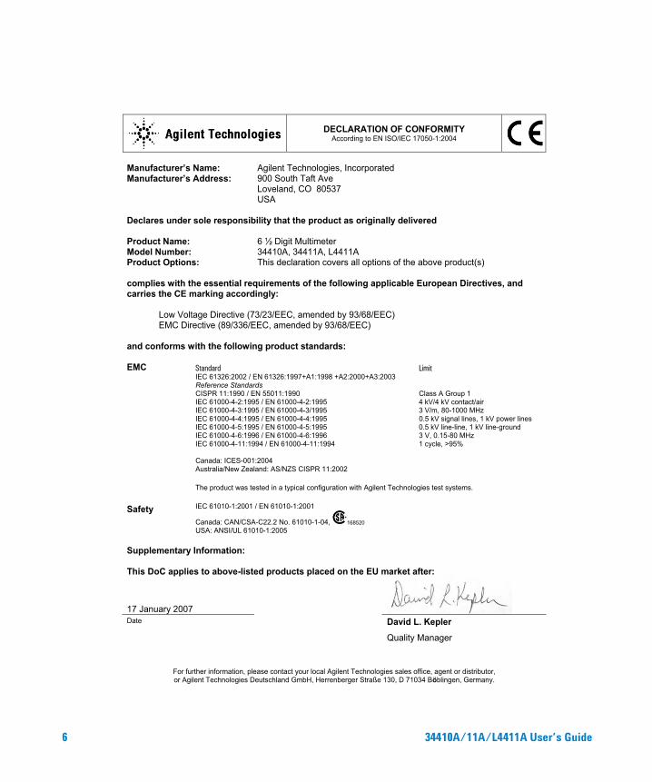
DECLARATION OF CONFORMITY According to EN ISO/IEC 17050-1:2004
Manufacturer’s Name: Agilent Technologies, Incorporated Manufacturer’s Address:
900 South Taft Ave Loveland, CO 80537 USA
Declares under sole responsibility that the product as originally delivered Product Name: 6 ½ Digit Multimeter Model Number: 34410A, 34411A, L4411A Product Options: This declaration covers all options of the above product(s) complies with the essential requirements of the following applicable European Directives, and carries the CE marking accordingly:
Low Voltage Directive (73/23/EEC, amended by 93/68/EEC) EMC Directive (89/336/EEC, amended by 93/68/EEC)
and conforms with the following product standards: EMC Standard Limit
IEC 61326:2002 / EN 61326:1997+A1:1998 +A2:2000+A3:2003 Reference Standards CISPR 11:1990 / EN 55011:1990 Class A Group 1 IEC 61000-4-2:1995 / EN 61000-4-2:1995 4 kV/4 kV contact/air IEC 61000-4-3:1995 / EN 61000-4-3/1995 3 V/m, 80-1000 MHz IEC 61000-4-4:1995 / EN 61000-4-4:1995 0.5 kV signal lines, 1 kV power lines IEC 61000-4-5:1995 / EN 61000-4-5:1995 0.5 kV line-line, 1 kV line-ground IEC 61000-4-6:1996 / EN 61000-4-6:1996 3 V, 0.15-80 MHz IEC 61000-4-11:1994 / EN 61000-4-11:1994 1 cycle, >95% Canada: ICES-001:2004 Australia/New Zealand: AS/NZS CISPR 11:2002
The product was tested in a typical configuration with Agilent Technologies test systems.
Safety IEC 61010-1:2001 / EN 61010-1:2001
Canada: CAN/CSA-C22.2 No. 61010-1-04, 168520 USA: ANSI/UL 61010-1:2005
Supplementary Information: This DoC applies to above-listed products placed on the EU market after:
17 January 2007
Date David L. Kepler
Quality Manager
For further information, please contact your local Agilent Technologies sales office, agent or distributor, or Agilent Technologies Deutschland GmbH, Herrenberger Straße 130, D 71034 Böblingen, Germany.
6 34410A/11A/L4411A User’s Guide
Agilent 34410A/11A/L4411A at a GlanceThe Agilent 34410A, 34411A, and L4411A multimeters provide 6½-digit, high-performance dc and ac measurements.
• Voltage and Current Measurements. DC and AC(true-rms).
• Resistance Measurements. 2-wire and 4-wire.
• Continuity and Diode Testing.
• Frequency and Period Measurements.
• Capacitance Measurements.
• Temperature Measurements. Thermistor and RTD.
• Auto and Manual Ranging.
• Math Features. Null, dB, dBm, limits, and statistics.
• Data Logging. Into non-volatile instrument memory.
• Instrument State Storage. User-defined named states.
• GPIB (IEEE-488), USB, and LAN. Three standard remote interfaces. LXI Class C Compliant.
• Web Interface. Direct web browser access to instrument.
• SCPI Compatibility. For easy instrument programming.
• Voltmeter Complete and External Trigger Signals. Synchronize with other instruments in your test system.
Note: This manual covers operation of the Agilent 34410A, 34411A, and L4411A 6½ Digit Multimeters. The features described in this manual, except where otherwise noted, apply to each of the multimeters.
Key Differences:Model 34410A Model 34411A/L4411A
• Up to 10,000 readings per second. • Up to 50,000 readings per second. • Reading memory (buffer) up
to 50,000 readings. • Reading memory (buffer) up
to 1 million readings. • Pretriggering, internal level triggering,
and digitizer specifications.
34410A/11A/L4411A User’s Guide 7
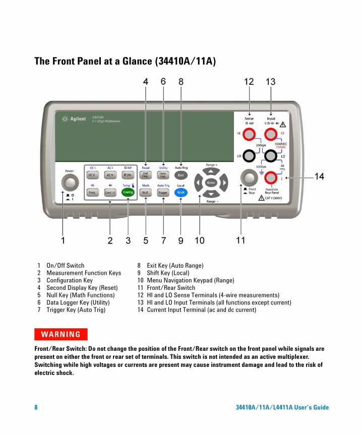
The Front Panel at a Glance (34410A/11A)
WARNING
Front/Rear Switch: Do not change the position of the Front/Rear switch on the front panel while signals are present on either the front or rear set of terminals. This switch is not intended as an active multiplexer. Switching while high voltages or currents are present may cause instrument damage and lead to the risk of electric shock.
1 On/Off Switch 8 Exit Key (Auto Range)2 Measurement Function Keys 9 Shift Key (Local)3 Configuration Key 10 Menu Navigation Keypad (Range)4 Second Display Key (Reset) 11 Front/Rear Switch5 Null Key (Math Functions) 12 HI and LO Sense Terminals (4-wire measurements)6 Data Logger Key (Utility) 13 HI and LO Input Terminals (all functions except current)7 Trigger Key (Auto Trig) 14 Current Input Terminal (ac and dc current)
8 34410A/11A/L4411A User’s Guide
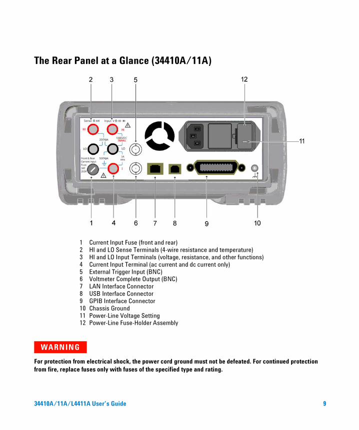
The Rear Panel at a Glance (34410A/11A)
WARNING
For protection from electrical shock, the power cord ground must not be defeated. For continued protection from fire, replace fuses only with fuses of the specified type and rating.
1 Current Input Fuse (front and rear)2 HI and LO Sense Terminals (4-wire resistance and temperature)3 HI and LO Input Terminals (voltage, resistance, and other functions)4 Current Input Terminal (ac current and dc current only)5 External Trigger Input (BNC)6 Voltmeter Complete Output (BNC)7 LAN Interface Connector8 USB Interface Connector9 GPIB Interface Connector10 Chassis Ground11 Power-Line Voltage Setting12 Power-Line Fuse-Holder Assembly
34410A/11A/L4411A User’s Guide 9
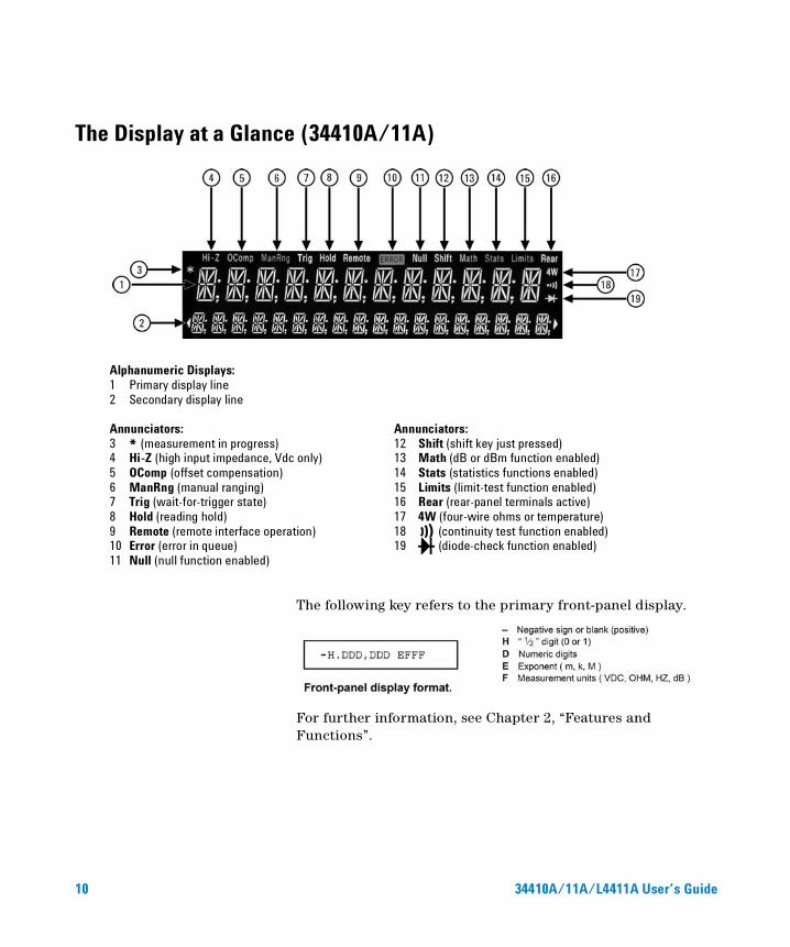
The Display at a Glance (34410A/11A)
The following key refers to the primary front-panel display.
For further information, see Chapter 2, “Features and Functions”.
Alphanumeric Displays:1 Primary display line2 Secondary display line
Annunciators: Annunciators:3 * (measurement in progress) 12 Shift (shift key just pressed)4 Hi-Z (high input impedance, Vdc only) 13 Math (dB or dBm function enabled) 5 OComp (offset compensation) 14 Stats (statistics functions enabled) 6 ManRng (manual ranging) 15 Limits (limit-test function enabled) 7 Trig (wait-for-trigger state) 16 Rear (rear-panel terminals active)8 Hold (reading hold) 17 4W (four-wire ohms or temperature) 9 Remote (remote interface operation) 18 (continuity test function enabled) 10 Error (error in queue) 19 (diode-check function enabled) 11 Null (null function enabled)
10 34410A/11A/L4411A User’s Guide
In This Guide…
1 Quick Start
In this chapter you prepare the multimeter for use and become familiar with the most common front-panel operations.
2 Features and Functions
In this chapter you will find a detailed description of the multimeter’s capabilities and operation. This chapter presents both front-panel and remote interface operation of the instrument.
Note. Refer to the Agilent 34410A/11A/L4411A Programmer’s Reference help system for a detailed description of the SCPI commands.
3 Remote Interface
This chapter describes how to connect the multimeter using a remote interface.
4 Measurement Tutorial
This chapter discusses measurement techniques and considerations to help you reduce sources of error and obtain the best accuracy from your instrument.
5 Specifications
This chapter lists the 34410A/11A/L4411A multimeter specifications and describes how to interpret these specifications.
34410A/11A/L4411A User’s Guide 11

12 34410A/11A/L4411A User’s Guide
Agilent 34410A/11A/L4411A 6½ Digit MultimeterUser’s Guide
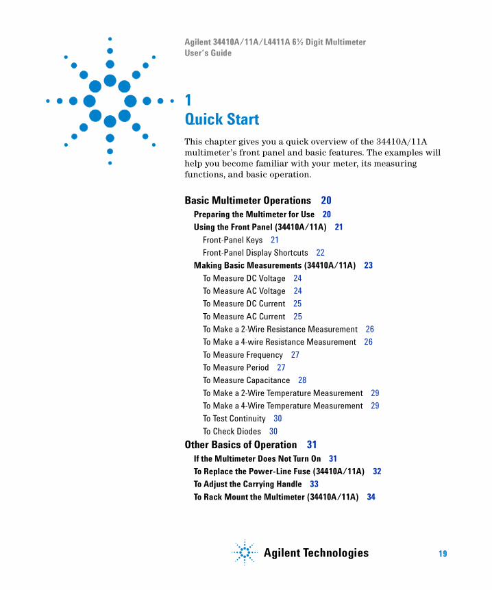
1Quick StartThis chapter gives you a quick overview of the 34410A/11A multimeter’s front panel and basic features. The examples will help you become familiar with your meter, its measuring functions, and basic operation.
Basic Multimeter Operations 20Preparing the Multimeter for Use 20
Using the Front Panel (34410A/11A) 21
Front-Panel Keys 21
Front-Panel Display Shortcuts 22
Making Basic Measurements (34410A/11A) 23
To Measure DC Voltage 24
To Measure AC Voltage 24
To Measure DC Current 25
To Measure AC Current 25
To Make a 2-Wire Resistance Measurement 26
To Make a 4-wire Resistance Measurement 26
To Measure Frequency 27
To Measure Period 27
To Measure Capacitance 28
To Make a 2-Wire Temperature Measurement 29
To Make a 4-Wire Temperature Measurement 29
To Test Continuity 30
To Check Diodes 30
Other Basics of Operation 31If the Multimeter Does Not Turn On 31
To Replace the Power-Line Fuse (34410A/11A) 32
To Adjust the Carrying Handle 33
To Rack Mount the Multimeter (34410A/11A) 34
19Agilent Technologies
1 Quick Start
Basic Multimeter Operations
This section introduces the basics of the 34410A/11A multimeter, and how to use it.
Preparing the Multimeter for Use
To verify that your 34410A or 34411A multimeter is ready for use:
1 Check the list of supplied items.
Verify that you have received the following items with your multimeter. If anything is missing, contact your nearest Agilent Sales Office.
• Test Lead Set.• Power Cord.• USB 2.0 Cable.• Agilent 34410A/11A/L4411A Product Reference CD–ROM.• Agilent Automation Ready (IO Libraries) CD–ROM.• Certificate of Calibration.
The product documentation, including the Agilent 34410A/11A/L4411A Programmer’s Reference Help and the product manuals, are included on the Product Reference CD–ROM. Printed (hardcopy) manuals are optional, and included only if you ordered them.
2 Connect the power cord and turn on the multimeter.
The front–panel display will light up while the multimeter performs its power–on self–test. The multimeter powers up in the dc voltage function with autoranging enabled (unless a previous user has configured power–up using a non–default stored state (see “Multimeter State Storage” on page 48).
NOTE For basic information unique to the L4411A, refer to the L4411A Getting Started Guide (p/n L4411-90001).
20 34410A/11A/L4411A User’s Guide
Quick Start 1
Using the Front Panel (34410A/11A)
This section introduces the 34410A/11A multimeter front panel.
Front-Panel Keys
The front panel provides keys to select various functions and operations. Pressing a measurement function key (e.g. ) selects that function. Press
to enter the configuration menu for the selected measurement function.
Most keys have a shifted function printed in blue above the key. To perform a shifted function, press , and then press the key that has the desired label above it.
To view and select menu items, use the menu navigation keypad (for example the or keys). The current (or default) selection is displayed in FULL BRIGHTNESS. All other choices are displayed in HALF BRIGHTNESS. The selections on each menu level scroll, but do not wrap. Arrow annunciators on the second display line indicate additional selections to the left or right. To accept a selection, press .
To set numeric parameters, use or to select a digit, and or to increase or decrease that digit.
34410A/11A/L4411A User’s Guide 21
1 Quick Start
Front-Panel Display Shortcuts
Direct front panel shortcuts are provided for three commonly used display functions: ranging, digit masking, and integration time.
Ranging. The multimeter’s manual range can be set directly from the navigation keypad.
To manually change the current multimeter range, press or . The ManRng annunciator will light, and the selected range (e.g. 100mV RANGE) will be briefly displayed on the second line.
Digit Masking. The navigation keypad provides a shortcut to mask (change the number of digits displayed) the reading on the main display, easing readability.
To enable digit masking during any measurement function, press or . DIGIT MASK will be displayed, along with a list of choices (3.5, 4.5, 5.5,
6.5 and AUTO) on the second display line. Press or to scroll through and select one of these settings, and then press
.
Integration Time (Bandwidth, Gate Time). Four measurement functions allow you to select the multimeter’s integration time: dc voltage, dc current, resistance, and temperature. The ac voltage and current measurements allow you to select the ac signal filter (bandwidth). The frequency/period function allows you to select gate time. The navigation keypad provides a shortcut for quickly changing these settings.
• If the multimeter is configured to take the measurement using an integration time in NPLCs, pressing or during front panel measurement operations will increase or decrease the integration time setting.
• If either the ac voltage or ac current measurement function is selected, pressing or during front panel measurement operations will increase or decrease the bandwidth setting.
• If the frequency/period measurement function is selected, pressing or during front panel measurement operations will increase or decrease
the gate time setting.
22 34410A/11A/L4411A User’s Guide
Quick Start 1
Making Basic Measurements (34410A/11A)
This section introduces the many types of measurements that you can make with your 34410A/11A multimeter, and how to make connections for each measurement. Most basic measurements can be taken using the factory default settings. A more complete description of all multimeter functions, measurement parameter configuration and remote interface operation is provided in Chapter 2.
For each measurement, connect the test leads as shown. The test lead connections are the same for the front or rear set of terminals.
Before making test lead connections, use the Front/Rear button on the front panel to select either the front or rear set of terminals. The Rear annunciator lights if the rear terminals are selected.
WARNING Do not press the Front/Rear button while signals are present on either the front or rear set of terminals. Switching while high voltages or currents are present can cause instrument damage, and may increase the risk of electric shock.
NOTE For basic measurement connection information unique to the L4411A, refer to the L4411A Getting Started Guide (p/n L4411-90001).
34410A/11A/L4411A User’s Guide 23
1 Quick Start
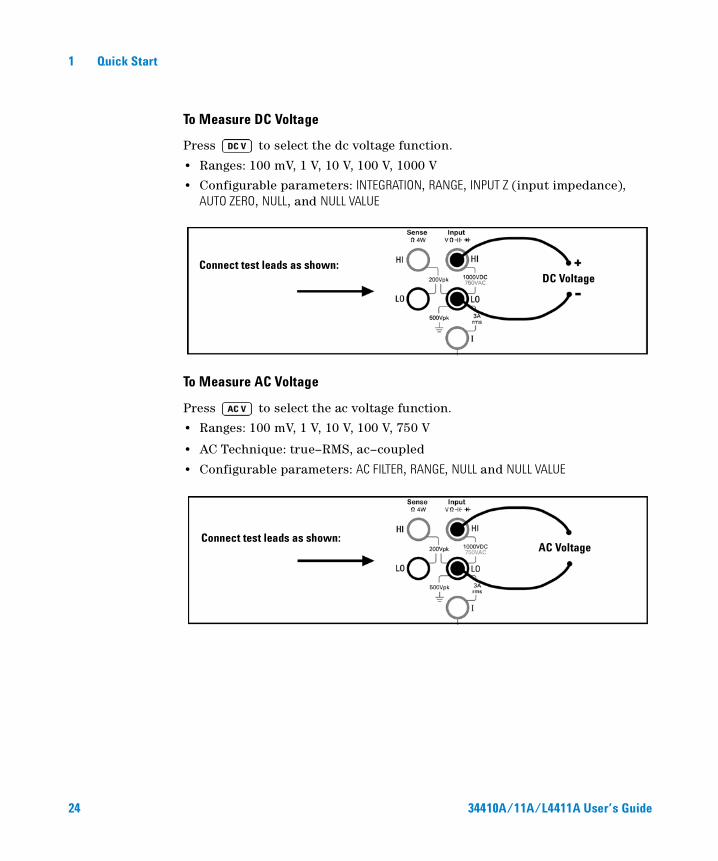
To Measure DC Voltage
Press to select the dc voltage function.
• Ranges: 100 mV, 1 V, 10 V, 100 V, 1000 V
• Configurable parameters: INTEGRATION, RANGE, INPUT Z (input impedance), AUTO ZERO, NULL, and NULL VALUE
To Measure AC Voltage
Press to select the ac voltage function.
• Ranges: 100 mV, 1 V, 10 V, 100 V, 750 V
• AC Technique: true–RMS, ac–coupled
• Configurable parameters: AC FILTER, RANGE, NULL and NULL VALUE
Connect test leads as shown:DC Voltage
Connect test leads as shown:AC Voltage
24 34410A/11A/L4411A User’s Guide
Quick Start 1
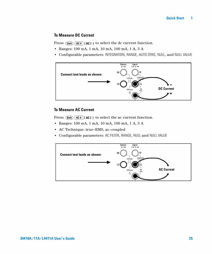
To Measure DC Current
Press to select the dc current function.
• Ranges: 100 mA, 1 mA, 10 mA, 100 mA, 1 A, 3 A
• Configurable parameters: INTEGRATION, RANGE, AUTO ZERO, NULL, and NULL VALUE
To Measure AC Current
Press to select the ac current function.
• Ranges: 100 mA, 1 mA, 10 mA, 100 mA, 1 A, 3 A
• AC Technique: true–RMS, ac–coupled
• Configurable parameters: AC FILTER, RANGE, NULL and NULL VALUE
Connect test leads as shown:
DC Current
Connect test leads as shown:
AC Current
34410A/11A/L4411A User’s Guide 25
1 Quick Start
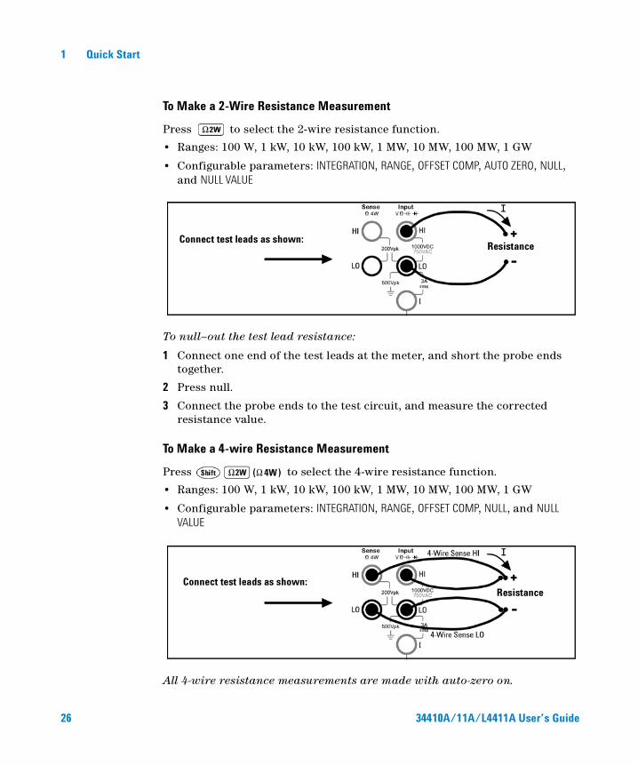
To Make a 2-Wire Resistance Measurement
Press to select the 2-wire resistance function.
• Ranges: 100 W, 1 kW, 10 kW, 100 kW, 1 MW, 10 MW, 100 MW, 1 GW
• Configurable parameters: INTEGRATION, RANGE, OFFSET COMP, AUTO ZERO, NULL, and NULL VALUE
To null–out the test lead resistance:
1 Connect one end of the test leads at the meter, and short the probe ends together.
2 Press null.
3 Connect the probe ends to the test circuit, and measure the corrected resistance value.
To Make a 4-wire Resistance Measurement
Press to select the 4-wire resistance function.
• Ranges: 100 W, 1 kW, 10 kW, 100 kW, 1 MW, 10 MW, 100 MW, 1 GW
• Configurable parameters: INTEGRATION, RANGE, OFFSET COMP, NULL, and NULL VALUE
All 4-wire resistance measurements are made with auto-zero on.
Connect test leads as shown:Resistance
Connect test leads as shown:Resistance
26 34410A/11A/L4411A User’s Guide

Quick Start 1
To Measure Frequency
Press to select the frequency function.
• Measurement band: 3 Hz to 300 kHz
• Input signal range: 100 mVAC to 750 VAC
• Technique: reciprocal counting
• Configurable parameters: GATE TIME, RANGE, AC FILTER, NULL and NULL VALUE
To Measure Period
Press to select the frequency function. Then press and select PERIOD from the menu.
• Measurement band: 0.33 s to 3.3 ms• Input signal range: 100 mVAC to 750 VAC• Technique: reciprocal counting• Configurable parameters: GATE TIME, RANGE, AC FILTER, NULL and NULL VALUE
Connect test leads as shown:AC Signal
Connect test leads as shown:AC Signal
34410A/11A/L4411A User’s Guide 27
1 Quick Start
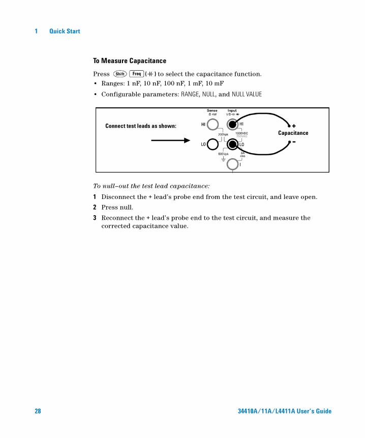
To Measure Capacitance
Press to select the capacitance function.• Ranges: 1 nF, 10 nF, 100 nF, 1 mF, 10 mF
• Configurable parameters: RANGE, NULL, and NULL VALUE
To null–out the test lead capacitance:
1 Disconnect the + lead’s probe end from the test circuit, and leave open.
2 Press null.
3 Reconnect the + lead’s probe end to the test circuit, and measure the corrected capacitance value.
Connect test leads as shown:Capacitance
28 34410A/11A/L4411A User’s Guide
Quick Start 1
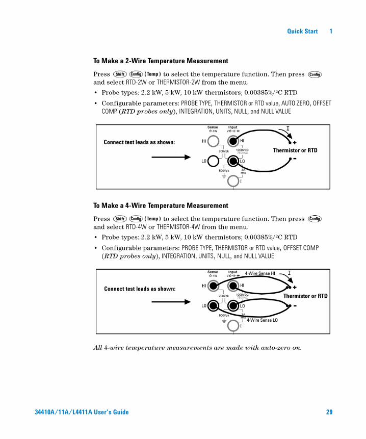
To Make a 2-Wire Temperature Measurement
Press to select the temperature function. Then press and select RTD-2W or THERMISTOR-2W from the menu.
• Probe types: 2.2 kW, 5 kW, 10 kW thermistors; 0.00385%/ºC RTD
• Configurable parameters: PROBE TYPE, THERMISTOR or RTD value, AUTO ZERO, OFFSET COMP (RTD probes only), INTEGRATION, UNITS, NULL, and NULL VALUE
To Make a 4-Wire Temperature Measurement
Press to select the temperature function. Then press and select RTD-4W or THERMISTOR-4W from the menu.
• Probe types: 2.2 kW, 5 kW, 10 kW thermistors; 0.00385%/ºC RTD
• Configurable parameters: PROBE TYPE, THERMISTOR or RTD value, OFFSET COMP (RTD probes only), INTEGRATION, UNITS, NULL, and NULL VALUE
All 4-wire temperature measurements are made with auto-zero on.
Connect test leads as shown:Thermistor or RTD
Connect test leads as shown:Thermistor or RTD
34410A/11A/L4411A User’s Guide 29
1 Quick Start
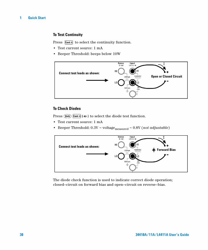
To Test Continuity
Press to select the continuity function.
• Test current source: 1 mA
• Beeper Threshold: beeps below 10W
To Check Diodes
Press to select the diode test function.
• Test current source: 1 mA
• Beeper Threshold: 0.3V ~ voltagemeasured ~ 0.8V (not adjustable)
The diode check function is used to indicate correct diode operation; closed–circuit on forward bias and open–circuit on reverse–bias.
Connect test leads as shown:Open or Closed Circuit
Connect test leads as shown:Forward Bias
30 34410A/11A/L4411A User’s Guide
Quick Start 1
Other Basics of Operation
This section covers basic troubleshooting and general use.
If the Multimeter Does Not Turn On
Use the following steps to help solve problems you might encounter when turning on the multimeter. If you need more help, see the Service Guide for instructions on returning the multimeter to Agilent for service.
1 Verify that there is ac power to the multimeter.
First, verify that the multimeter’s Power switch is in the “On” position. Also, make sure that the power cord is firmly plugged into the power module on the rear panel. You should also make sure that the power source you plugged the multimeter into is energized.
2 Verify the power–line voltage setting.
The line voltage is set to the proper value for your country when the multimeter is shipped from the factory. Change the voltage setting if it is not correct. The settings are: 100, 120, 220, or 240 Vac (for 230 Vac operation, use the 220 Vac setting).
See “To Replace the Power-Line Fuse (34410A/11A)” on page 32 if you need to change the line–voltage setting.
3 Verify that the power–line fuse is good.
The multimeter is shipped from the factory with a power–line fuse installed. The supplied fuse is a 250 mAT, 250V, slow–blow, 5x20mm fuse, Agilent part number 2110–0817. If you determine that the fuse is faulty, replace it with one of the same size and rating.
See “To Replace the Power-Line Fuse (34410A/11A)” on page 32 if you need to replace the power–line fuse.
The current input path is also fused. The supplied fuse is a 3 AT, 250V, slow–blow, 5x20mm fuse, Agilent part number 2110–0780, and is housed in a standard screw–in fuse holder on the left side of the rear panel. If you determine that the fuse is faulty, replace it with one of the same size and rating.
34410A/11A/L4411A User’s Guide 31
1 Quick Start
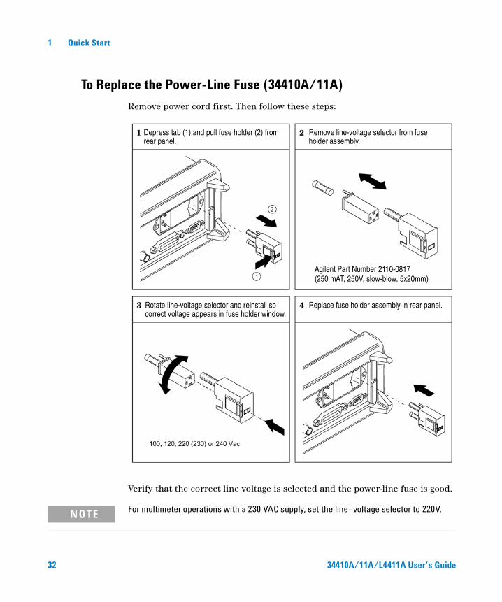
To Replace the Power-Line Fuse (34410A/11A)
Remove power cord first. Then follow these steps:
Verify that the correct line voltage is selected and the power-line fuse is good.
Depress tab (1) and pull fuse holder (2) from Remove line-voltage selector from fuseholder assembly.
Rotate line-voltage selector and reinstall so correct voltage appears in fuse holder window.
Replace fuse holder assembly in rear panel.
Agilent Part Number 2110-0817(250 mAT, 250V, slow-blow, 5x20mm)
rear panel.
NOTE For multimeter operations with a 230 VAC supply, set the line–voltage selector to 220V.
32 34410A/11A/L4411A User’s Guide
Quick Start 1
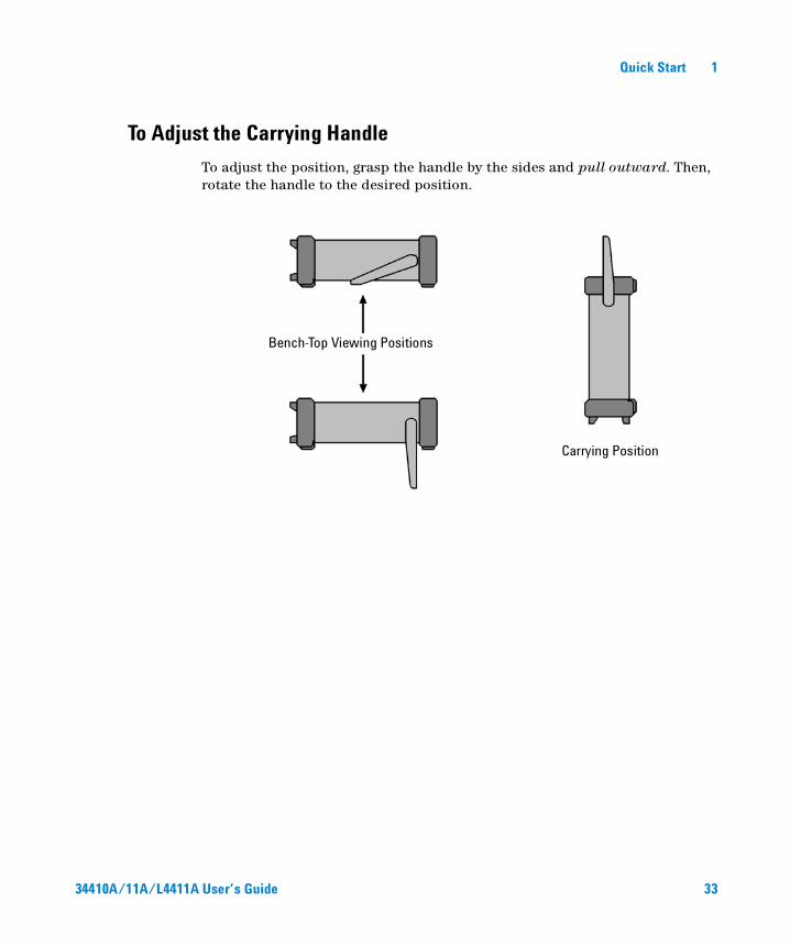
To Adjust the Carrying Handle
To adjust the position, grasp the handle by the sides and pull outward. Then, rotate the handle to the desired position.
Bench-Top Viewing Positions
Carrying Position
34410A/11A/L4411A User’s Guide 33

1 Quick Start
To Rack Mount the Multimeter (34410A/11A)
You can mount the 34410A/11A in a standard 19–inch rack cabinet using the available rack–mount kits. Instructions and mounting hardware are included with each kit. Any Agilent System II (half-width, 2U height) instrument of either the 272.3 mm or the 348.3 mm depth can be rack mounted side–by–side with the 34410A/11A. For example, a 34410A/11A and a 34401A, or two 34410A/11As, can be mounted side–by–side, as shown below.
You must remove the carrying handle, and the front and rear rubber bumpers, before rack mounting an instrument.
To remove each bumper, stretch a corner and slide it off.
To remove the handle, rotate it to the vertical position and pull the ends outward.
To rack mount a single instrument, order adaptor kit 5063-9240
To rack mount two instruments side-by-side, order lock-link kit 5061-8769 and flange kit 5063-9212
NOTE Refer to the L4411A Getting Started Guide for procedures and part numbers for rack mounting the L4411A.
34 34410A/11A/L4411A User’s Guide
Contents
1 Quick Start 19
Basic Multimeter Operations 20
Preparing the Multimeter for Use 20
Using the Front Panel 21Front-Panel Keys 21Front-Panel Display Shortcuts 22
Making Basic Measurements 23To Measure DC Voltage 24To Measure AC Voltage 24To Measure DC Current 25To Measure AC Current 25To Make a 2-Wire Resistance Measurement 26To Make a 4-wire Resistance Measurement 26To Measure Frequency 27To Measure Period 27To Measure Capacitance 28To Make a 2-Wire Temperature Measurement 29To Make a 4-Wire Temperature Measurement 29To Test Continuity 30To Check Diodes 30
Other Basics of Operation 31
If the Multimeter Does Not Turn On 31
To Replace the Power-Line Fuse 32
To Adjust the Carrying Handle 33
To Rack Mount the Multimeter 34
34410A/11A User’s Guide 35
Contents
2 Features and Functions 35
SCPI Commands 37
Front Panel Features (34410A/11A) 38
Front Panel Display 38Displayed Messages 38Self–Guiding Menus 38Annunciators 40Second Display Options 41Turning the Display Off 41Front–Panel Display Shortcuts 42Front Panel Alphanumeric Character Entry 43
Front Panel Measurement Configuration Menus 44Configuring DC Voltage and DC Current Measurements 44Configuring AC Voltage and Current Measurements 45Configuring Resistance Measurements 45Configuring Frequency and Period Measurements 46Configuring Temperature Measurements 46Configuring Capacitance Measurements 47Continuity and Diode Tests 47
Advanced Configuration Options 48
Multimeter State Storage 48
Accessing Reading Memory 49
Front/Rear Input Terminal Switching (34410A/11A) 49
Multimeter Reset 50
DC Measurements 51Integration Time and Resolution 51DC Input Impedance 53
AC Measurements 54AC Filter 54Gate Time 55
Auto Zero 56
Ranging 57
Null Measurements 59
36 34410A/11A/L4411A User’s Guide

Contents
Miscellaneous Configuration Settings 60Radix Character (34410A/11A) 60Thousands Separator (34410A/11A) 60Beeper (34410A/11A) 61
Math Functions 62dB Measurements 63dBm Measurements 64Using Statistics 65Limit Testing 66
Triggering the Multimeter 67
Selecting a Trigger Source 67Auto Triggering (34410A/11A) 68Single Triggering (34410A/11A) 68Reading Hold (34410A/11A) 69Immediate Triggering 69Software (Bus) Triggering 70Internal (Level) Triggering (34411A/L4411A) 70Number of Samples per Trigger 71Number of Pre-Trigger Samples (34411A/L4411A) 71Trigger Delay 72Automatic Trigger Delay 73External Triggering 75Trigger Slope 77
Data Logging 78
System-Related Operations 82
Self–Test 82Error Conditions 83Reading the Error Queue 84Calibration 84
Power-On and Reset State 85
34410A/11A/L4411A User’s Guide 37
Contents
3 Remote Interface Configuration 87
Configuring the GPIB Interface 89
Configuring the USB Interface 90
Configuring the LAN Interface 91
Configuring LAN Parameters 92DHCP 92Auto–IP 92IP Address 93Subnet Mask 93Default Gateway 94Host Name 94DNS Server 95Web Password 95Instrument Unexpectedly Goes into Remote 95
Setting up a LAN connection from the Front Panel 96
Setting up a LAN connection from the Remote Interface 97
Agilent 34410A/11A Web Interface 98
4 Measurement Tutorial 99
DC Measurement Considerations 101
Thermal EMF Errors 101Loading Errors (dc volts) 101
Noise Rejection 102Rejecting Power–Line Noise Voltages 102Common Mode Rejection (CMR) 102Noise Caused by Magnetic Loops 103Noise Caused by Ground Loops 103
Resistance Measurement Considerations 1044–Wire Ohms Measurements 104Removing Test Lead Resistance Errors 105Minimizing Power Dissipation Effects 105Errors in High Resistance Measurements 105
True RMS AC Measurements 106
38 34410A/11A/L4411A User’s Guide
Contents
True RMS Accuracy and High–Frequency Signal Content 107Estimating High–Frequency (Out–of–Band) Error 110
Other Primary Measurement Functions 112
Frequency and Period Measurement Errors 112
DC Current Measurements 112
Capacitance Measurements 113
Temperature Measurements 115Probe Type Choice 1152–Wire vs. 4–Wire Measurements 115Auto Zero On/Off 116Integration 116Offset Compensation 116NULL Reading: 116
High-Speed Measurements 117
Making High–Speed AC Measurements 117Making High–Speed dc and Resistance Measurements 118
Other Sources of Measurement Error 119
Settling Time Effects 119Loading Errors (ac volts) 119Measurements Below Full Scale 120High–Voltage Self–Heating Errors 120AC Current Measurement Errors (Burden Voltage) 120Low–Level Measurement Errors 120Common Mode Errors 122Leakage Current Errors 122
34410A/11A/L4411A User’s Guide 39
Contents
5 Specifications 123
DC Characteristics 125
AC Characteristics 128
Frequency and Period Characteristics 130
Capacitance Characteristics 132
Temperature Characteristics 132
Additional 34411A Specifications 133
Measurement and System Speeds 134System Speeds 135Data From Memory 136
General Specifications 136Dimensions 138
To Calculate Total Measurement Error 139
Interpreting Accuracy Specifications 141Transfer Accuracy 14124–Hour Accuracy 14190–Day and 1–Year Accuracy 141Temperature Coefficients 141
Configuring for Highest Accuracy Measurements 142DC Voltage, DC Current, and Resistance Measurements: 142AC Voltage and AC Current Measurements: 142Frequency and Period Measurements: 142
6 Appendix: Firmware and Driver Updates 143
Downloading the Update Utility and Firmware 144
Downloading and Installing the Firmware Update 144
Downloading IVI-COM Driver Updates 147
40 34410A/11A/L4411A User’s Guide
Agilent 34410A/11A/L4411A 6½ Digit Multimeter User’s Guide
2Features and FunctionsSCPI Commands 37
Front Panel Features (34410A/11A) 38Front Panel Display 38
Displayed Messages 38
Self–Guiding Menus 38
Annunciators 40
Second Display Options 41
Turning the Display Off 41
Front–Panel Display Shortcuts 42
Front Panel Alphanumeric Character Entry 43
Front Panel Measurement Configuration Menus 44
Configuring DC Voltage and DC Current Measurements 44
Configuring AC Voltage and Current Measurements 45
Configuring Resistance Measurements 45
Configuring Frequency and Period Measurements 46
Configuring Temperature Measurements 46
Configuring Capacitance Measurements 47
Continuity and Diode Tests 47
Advanced Configuration Options 48Multimeter State Storage 48
Accessing Reading Memory 49
Front/Rear Input Terminal Switching (34410A/11A) 49
Multimeter Reset 50
DC Measurements 51
Integration Time and Resolution 51
DC Input Impedance 53AC Measurements 54
AC Filter 54
35Agilent Technologies
2 Features and Functions
Gate Time 55
Auto Zero 56
Ranging 57
Null Measurements 59
Miscellaneous Configuration Settings 60
Radix Character (34410A/11A) 60
Thousands Separator (34410A/11A) 60
Beeper (34410A/11A) 61
Math Functions 62
dB Measurements 63dBm Measurements 64Using Statistics 65Limit Testing 66
Triggering the Multimeter 67Selecting a Trigger Source 67
Auto Triggering (34410A/11A) 68
Single Triggering (34410A/11A) 68
Reading Hold (34410A/11A) 69
Immediate Triggering 69
Software (Bus) Triggering 70
Internal (Level) Triggering (34411A/L4411A) 70
Number of Samples per Trigger 71
Number of Pre-Trigger Samples (34411A/L4411A) 71
Trigger Delay 72
Automatic Trigger Delay 73
External Triggering 75
Trigger Slope 77
Data Logging 78System-Related Operations 82
Self–Test 82
Error Conditions 83
Reading the Error Queue 84
Calibration 84
Power-On and Reset State 85
36 34410A/11A/L4411A User’s Guide

Features and Functions 2
SCPI Commands
The Agilent 34410A/11A/L4411A complies with the syntax rules and conventions of SCPI (Standard Commands for Programmable Instruments).
SCPI Language Conventions. Throughout this guide, the following conventions are used for SCPI command syntax for remote interface programming:
• Braces ( ) enclose the parameter choices for a given command string. The braces are not sent with the command string.
• A vertical bar ( | ) separates multiple parameter choices for a given command string.
• Triangle brackets ( < > ) indicate that you must specify a value for the enclosed parameter. The brackets are not sent with the command string.
• Some parameters are enclosed in square brackets ( [ ] ). This indicates that the parameter is optional and can be omitted. The brackets are not sent with the command string. If you do not specify a value for an optional parameter, the instrument chooses a default value.
SCPI Language Version. You can determine the SCPI version to which your instrument adheres by sending a command from the remote interface.
• You can query the SCPI version from the remote interface only.
• Remote Interface Operation: The SYSTem:VERSion? query returns the SCPI version in the form “YYYY.V”, where “YYYY” represents the year of the version, and “V” represents a version number for that year (for example, 1994.0).
NOTE For complete SCPI command syntax information, refer to the Agilent 34410A/11A/L4411A Programmer’s Reference Help. This is a standard Windows help system, provided on the Agilent 34410A/11A/L4411A Product Reference CD-ROM that came with your instrument.
34410A/11A/L4411A User’s Guide 37

2 Features and Functions
Front Panel Features (34410A/11A)
Front Panel Display
The Agilent 34410A/11A provides a two–line, alphanumeric display, with annunciators to indicate certain non–default instrument states.
Displayed Messages
While taking measurements, the primary display line shows the current reading, with units (for example: “-0.001,02 VDC”). For some functions the second display line can be enabled to display a secondary measurement.
When a menu is open (for example, to configure a measurement), the primary display line indicates the menu, or the parameter to be set or selected, while the second line displays the selections, or a value to be set.
The second line also displays momentary messages to convey instrument state changes.
Self–Guiding Menus
The Agilent 34410A/11A provides context–sensitive menus to configure measurements and other functions. The following general guidelines apply to menu operations.
• In this guide, “navigation keypad” refers to the , , , and keys, and the key.
• Several keys (or shifted key sequences) open a menu. These include:
• to configure the currently selected measurement function.
• to select a secondary measurement for the second display line.
• to set up and use the data logger function.
• to turn on and select the math functions.
• to return the multimeter to auto trigger mode, enable reading hold, or select various triggering options.
• to configure utility options or the remote interface.
• to reset the multimeter to its reset state (equivalent to the *RST command in SCPI).
• When you press , the Shift annunciator is lit. It toggles on and off.
38 34410A/11A/L4411A User’s Guide
Features and Functions 2
• If the multimeter is in the remote interface mode (Remote annunciator is lit), pressing (Local) once returns the multimeter to local (front panel) operation.
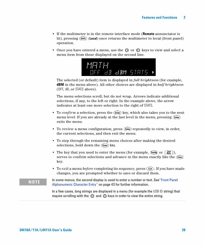
• Once you have entered a menu, use the or keys to view and select a menu item from those displayed on the second line.
The selected (or default) item is displayed in full brightness (for example, dBM in the menu above). All other choices are displayed in half brightness (OFF, dB, or STATS above).
The menu selections scroll, but do not wrap. Arrows indicate additional selections, if any, to the left or right. In the example above, the arrow indicates at least one more selection to the right of STATS.
• To confirm a selection, press the key, which also takes you to the next menu level. If you are already at the last level in the menu, pressing exits the menu.
• To review a menu configuration, press repeatedly to view, in order, the current selections, and then exit the menu.
• To step through the remaining menu choices after making the desired selections, hold down the key.
• The key that you used to enter the menu (for example, or ), serves to confirm selections and advance in the menu exactly like the key.
• To exit a menu before completing its sequence, press . If you have made changes, you are prompted whether to save or discard them.
NOTE In some menus, the second display is used to enter a number or text. See“Front Panel Alphanumeric Character Entry” on page 43 for further information.
In a few cases, long strings are displayed in a menu (for example the USB ID string) that require scrolling with the and keys in order to view the entire string.
34410A/11A/L4411A User’s Guide 39
2 Features and Functions
Annunciators
There are several annunciators, mostly in a line at the top of the display. Each annunciator lights to indicate a particular non–default meter state:
• * A measurement is in progress (the “sample annunciator”).
• Hi–Z For DC voltage measurements in the 100 mV, 1 V or 10 V ranges, an input impedance of >10 GΩ is configured.
• OComp For resistance measurements in the 100 Ω, 1 kΩ and 10 kΩ ranges, offset compensation is enabled.
• ManRng For the selected measurement function, a manual range is selected (autoranging is off).
• Trig Triggering is enabled. The meter is in the “wait–for–trigger” state.
• Hold The reading hold function is enabled.
• Remote The multimeter is operating in the remote interface mode.
• Error A hardware error or remote interface error has been detected, and a message is in the error queue.
• Null The null feature is enabled for the present measurement function.
• Shift The key has been pressed (toggles on and off).
• Math Either the dB or dBm math function is enabled.
• Stats The statistics math function is enabled.
• Limits The limit test math function is enabled.
• Rear The Front/Rear switch is set to Rear and the rear set of input terminals is connected internally to make measurements.
• 4W A four–wire resistance or temperature function is selected.
• The continuity function is selected.
• The diode test function is selected.
40 34410A/11A/L4411A User’s Guide
Features and Functions 2
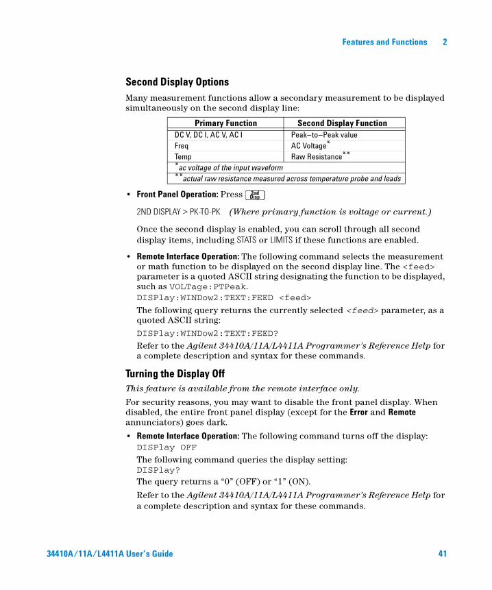
Second Display Options
Many measurement functions allow a secondary measurement to be displayed simultaneously on the second display line:
• Front Panel Operation: Press
2ND DISPLAY > PK-TO-PK (Where primary function is voltage or current.)
Once the second display is enabled, you can scroll through all second display items, including STATS or LIMITS if these functions are enabled.
• Remote Interface Operation: The following command selects the measurement or math function to be displayed on the second display line. The <feed> parameter is a quoted ASCII string designating the function to be displayed, such as VOLTage:PTPeak.DISPlay:WINDow2:TEXT:FEED <feed>
The following query returns the currently selected <feed> parameter, as a quoted ASCII string:DISPlay:WINDow2:TEXT:FEED?
Refer to the Agilent 34410A/11A/L4411A Programmer’s Reference Help for a complete description and syntax for these commands.
Turning the Display OffThis feature is available from the remote interface only.
For security reasons, you may want to disable the front panel display. When disabled, the entire front panel display (except for the Error and Remote annunciators) goes dark.
• Remote Interface Operation: The following command turns off the display:DISPlay OFF
The following command queries the display setting:DISPlay?The query returns a “0” (OFF) or “1” (ON).
Refer to the Agilent 34410A/11A/L4411A Programmer’s Reference Help for a complete description and syntax for these commands.
Primary Function Second Display FunctionDC V, DC I, AC V, AC I Peak–to–Peak valueFreq AC Voltage*Temp Raw Resistance***ac voltage of the input waveform**actual raw resistance measured across temperature probe and leads
34410A/11A/L4411A User’s Guide 41
2 Features and Functions
Front–Panel Display Shortcuts Direct front–panel shortcuts are provided for three commonly used display functions: ranging, digit masking, and integration time. These shortcuts are available only when you are not in a menu.
Ranging. The meter range can be set directly from the navigation keypad.
• To manually change the range, press or . The ManRng annunciator lights, and the selected range (for example, 100mV RANGE) is briefly displayed on the second line.
• To toggle between the selected manual range and autoranging, press . The ManRng annunciator toggles on or off, as appropriate.
Note: This is a dual–function key, not a shifted key. Pressing when in a menu will exit the menu.
Digit Masking. The navigation keypad provides a shortcut to mask (change the number of digits displayed) the reading on the main display.
• To enable digit masking for the selected measurement function, press or . DIGIT MASK will be displayed, along with a list of choices
(3.5, 4.5, 5.5, 6.5 and AUTO). Select the desired setting (use the keys) and press .
• Masking digits only affects what is displayed. It does not affect measurement speed or accuracy.
Integration Time (Bandwidth, Gate Time). Four measurement functions allow you to select the integration time: dc voltage, dc current, resistance, and temperature. The ac voltage and ac current measurements allow you to select the ac signal filter (bandwidth). The frequency/period function allows you to select gate time. The navigation keypad provides a shortcut for quickly changing these settings.
• If the multimeter is configured to take the measurement using an integration time in NPLCs, press or to increase or decrease the integration time setting and display the new setting briefly. You can scroll through the entire range of integration time settings:
Agilent 34410A, PLCs: 0.006, 0.02, 0.06, 0.2, 1, 2, 10 and 100
Agilent 34411A/L4411A, PLCs: 0.001, 0.002, 0.006, 0.02, 0.06, 0.2, 1, 2, 10, 100
42 34410A/11A/L4411A User’s Guide
Features and Functions 2
• If the multimeter is configured to take the measurement using an aperture integration time, press or to display APERTURE, with the current setting on the second line (for example, 101.005mSEC). You can then use the navigation keypad to change the aperture setting. The and keys have their usual functions.
• If either the ac voltage or ac current function is selected, press or to increase or decrease the bandwidth setting, and briefly display the new setting on the second line. You can scroll through the three available bandwidth settings: 3 HZ : SLOW, 20 HZ : MEDIUM, or 200 HZ : FAST.
• If the frequency/period measurement function is selected, pressing or during front panel measurement operations will increase or decrease
the gate time setting, and briefly display the new setting on the second display line (for example, if the setting was 0.1 GATE TIME, the display will show 0.01 GATE TIME when you press ). Repeated use of or will scroll through the selection of gate time settings in seconds (0.001 GATE TIME, 0.01 GATE TIME, 0.1 GATE TIME, and 1 GATE TIME).
Front Panel Alphanumeric Character Entry
When you are in certain menus, particularly the utility menus, you may need to manually enter a number or alphanumeric string on the second display line.
• To enter a number or character, press or to select the displayed character (digit or letter) you wish to edit. The selected character will flash to indicate it can be edited. Use the and keys to modify a digit (from 0 to 9) or a letter (from A to Z).
• To quickly enter large numbers, you may press to scroll over to the most significant digit allowed and/or add leading zeros. For non–zero floating–point entries, you may also press to scroll to the magnitude prefix (for example, u, m, k, M), then use the and keys to change the numerical entry.
Arrow annunciators on the second display line will indicate if there are editable characters left or right of the one selected.
34410A/11A/L4411A User’s Guide 43
2 Features and Functions
Front Panel Measurement Configuration MenusEach measurement function is configured separately, except for Ω 2W and Ω 4W (which are partially inter–dependent), and frequency and period, (which share a configuration menu). The configuration settings (for example, integration, and range) for each measurement function are retained when switching between functions.• To enter the configuration menu for any selected measurement function, press
. The menus are context–sensitive; only the options applicable to the selected function will appear.
• When digit masking is enabled (see “Digit Masking.” on page 42) the DIGIT MASK submenu will appear before other configuration choices.
• For further information, see “Advanced Configuration Options” on page 48.
Configuring DC Voltage and DC Current MeasurementsFor dc voltage and dc current measurements, the menu selections are: INTEGRATION, RANGE, AUTO ZERO, NULL and NULL VALUE. For dc voltage measurements only, you can also configure INPUT Z.• INTEGRATION: Allows you to set the integration time for the measurement in
two ways; in power–line cycles (select NPLC) or in seconds (select APERTURE).• RANGE: Allows you to select a fixed range (select MANUAL), or let the
multimeter automatically select the range using the autoranging feature (select AUTO).
• INPUT Z: Allows you to select an input impedance of 10 MΩ (select 10 M) or >10 GΩ (select HI–Z) for the 100 mVdc, 1 Vdc and 10 Vdc ranges only.
• AUTO ZERO: Allows you to enable for all readings (select ON), enable for one reading (select ONCE), or disable (select OFF) the auto zero feature, which subtracts a zero reading from each measurement.
• NULL: Allows you to enable (ON) or disable (OFF) the null measurement feature, which measures the difference between a stored null value and the input signal.
• NULL VALUE: Allows you to view and edit the null value (if enabled).
44 34410A/11A/L4411A User’s Guide
Features and Functions 2
Configuring AC Voltage and Current MeasurementsFor ac voltage and ac current measurements, your menu selections are: AC FILTER, RANGE, NULL and NULL VALUE.
• AC FILTER: Allows you to select one of three choices (3 HZ : SLOW, 20 HZ : MEDIUM, 200 HZ : FAST). The ac filter allows you to trade off low–frequency bandwidth versus ac settling time.
• RANGE: Allows you to let the multimeter automatically select the range using the autoranging feature (select AUTO), or you may select a fixed range (select MANUAL).
• NULL: Allows you to enable (ON) or disable (OFF) the null measurement feature, which measures the difference between a stored null value and the input signal.
• NULL VALUE: Allows you to view and edit the null value (if enabled).
Configuring Resistance MeasurementsFor 2–wire and 4–wire resistance measurements, your menu selections are: INTEGRATION, RANGE, OFFSET COMP, AUTO ZERO, NULL and NULL VALUE.
• INTEGRATION: Allows you to set the integration time for the measurement in two ways; in power–line cycles (NPLC) or in seconds (APERTURE).
• RANGE: Allows you to let the multimeter automatically select the range using the autoranging feature (select AUTO), or you may select a fixed range (select MANUAL).
• OFFSET COMP: Allows you to enable (ON) or disable (OFF) the offset compensation feature. With offset compensation enabled, the multimeter makes a normal resistance measurement first, followed by a second measurement to determine any offset voltage in the input circuitry. The resultant displayed measurement corrects for this offset. Enabling offset compensation increases measurement time.
• AUTO ZERO: Allows you to enable for all readings (ON), enable for one reading (ONCE), or disable (OFF) the auto zero feature, which subtracts a subsequent zero reading from each measurement.
• NULL: Allows you to enable (ON) or disable (OFF) the null measurement feature, which measures the difference between a stored null value and the input signal.
• NULL VALUE: Allows you to view and edit the null value (if enabled).
34410A/11A/L4411A User’s Guide 45
2 Features and Functions
Configuring Frequency and Period Measurements
For frequency and period measurements, your menu selections are: CONFIGURE, GATE TIME, RANGE, AC FILTER, NULL and NULL VALUE.
• CONFIGURE: Allows you to select either FREQUENCY or PERIOD as the primary measurement.
• GATE TIME: Allows you to select one of four choices (0.001, 0.01, 0.1, or 1) for gate time, in seconds.
• RANGE: Allows you to let the multimeter automatically select the range using the autoranging feature (select AUTO), or you may select a fixed range (select MANUAL).
• AC FILTER: Allows you to select from three choices (3 HZ : SLOW, 20 HZ : MEDIUM, or 200 HZ : FAST). The ac filter allows you to trade off low–frequency bandwidth versus ac settling time.
• NULL: Allows you to enable (ON) or disable (OFF) the null measurement feature, which measures the difference between a stored null value and the input signal.
• NULL VALUE: Allows you to view and edit the null value (if enabled).
Configuring Temperature Measurements
For temperature measurements, your menu selections are: PROBE TYPE, OFFSET COMP, AUTO ZERO, INTEGRATION, NULL, NULL VALUE, and UNITS.
• PROBE TYPE: Allows you to select from four choices (RTD–4W, RTD–2W, THERMISTOR–2W, or THERMISTOR–4W) of temperature probe type.
• OFFSET COMP (for RTD probes only): Allows you to enable (ON) or disable (OFF) the offset compensation feature. With offset compensation enabled, the multimeter makes a normal temperature measurement first, followed by a second measurement to determine any offset voltage in the input circuitry. The resultant displayed measurement corrects for this offset. Enabling offset compensation increases measurement time.
• AUTO ZERO: Allows you to enable (ON) or disable (OFF) the auto zero feature for 2–wire temperature measurements. This feature subtracts a subsequent zero reading from each measurement.
Note that 4–wire temperature measurements are automatically made with auto zero always on.
• INTEGRATION: Allows you to set the integration time for the measurement in two ways; in power–line cycles (NPLC) or in seconds (APERTURE).
46 34410A/11A/L4411A User’s Guide

Features and Functions 2
• NULL: Allows you to enable (ON) or disable (OFF) the null measurement feature, which measures the difference between a stored null value and the input signal.
• NULL VALUE: Allows you to view and edit the null value (if enabled).
• UNITS: Allows you to select the temperature scale: Celsius (select C), Fahrenheit (select F), or Kelvin (select K).
Configuring Capacitance Measurements
For capacitance measurements, your configuration menu choices are: RANGE, NULL and NULL VALUE.
• RANGE: Allows you to let the multimeter automatically select the range using the autoranging feature (select AUTO), or you may select a fixed range (select MANUAL).
• NULL: Allows you to enable (ON) or disable (OFF) the null measurement feature, which measures the difference between a stored null value and the input signal.
• NULL VALUE: Allows you to view and edit the null value (if enabled).
Continuity and Diode Tests
There are no parameters to configure, nor any menus for these functions.
• Continuity Test. The range and resolution are fixed for continuity tests.
• The range is 1 kΩ (a 2-wire resistance measurement).
• The meter beeps (even if beep is disabled) for each measurement that is less than or equal to the continuity threshold (which is 10 Ω), and the actual resistance reading is displayed on the front panel.
• From 10 Ω to 1.2 kΩ the meter displays the actual resistance reading with no beep. If the reading exceeds 1.2 kΩ, the meter displays "OPEN" on the front panel (no beep).
• Diode Test. The range and resolution are fixed for diode tests.
• The range is 1 Vdc (with a 1 mA current source output).
• The voltage is displayed on the front panel if it is in the 0 to 1.2 volt range. The meter beeps when the signal transitions to the 0.3 to 0.8 volt threshold (unless beep is disabled). If the signal is greater than 1.2 volts, "OPEN" is displayed on the front panel.
34410A/11A/L4411A User’s Guide 47

2 Features and Functions
Advanced Configuration Options
Multimeter State Storage
The present multimeter state, including all settings for measurement configuration, math operations, triggering operations, system operations and I/O configuration, can be saved in one of five non–volatile stored states and later recalled. State 0 (POWER_DOWN) retains the multimeter configuration at power down. States 1 – 4 (STATE_1, STATE_2, STATE_3, STATE_4) are available for storing other configurations.
• Front Panel Operation: Press to open the utility menu.
• To store the present multimeter state (for example, to STATE_1):
UTILITY MENU > STORE/RECALL > STORE > STORE STATE > 1: STATE_1 > CHANGE NAME
Use the navigation keypad to enter a new name (up to 12 characters), or just press to store with the default name.
• To recall any of five stored states (for example: STATE_1):
UTILITY MENU > STORE/RECALL > RECALL > RECALL STATE > 1: STATE_1
• To delete a state you have stored (for example: STATE_1):
UTILITY MENU > STORE/RECALL > DELETE > DELETE STATE > 1: STATE_1
• To rename a state you have stored (for example: STATE_1):
UTILITY MENU > STORE/RECALL > RENAME > RENAME STATE > 1: STATE_1 > CHANGE NAME
Use the navigation keypad to enter a new name (up to 12 characters), or just press to store with the current name.
• To select any previously stored state (0 – 4) as the power–on default state (for example: STATE_1):
UTILITY MENU > STORE/RECALL > PWR-ON > PWR-ON AUTO > ON > PWR-ON STATE > 1: STATE_1
NOTE The Remote Interface Operation segments within the following topics describes how the instrument feature is used/accessed from a (remote) programming environment. For the L4411A, this represents the only method of accessing the instrument. See the L4411A Getting Started Guide for details.
48 34410A/11A/L4411A User’s Guide

Features and Functions 2
• Remote Interface Operation: Refer to the MEMory command subsystem in the Agilent 34410A/11A/L4411A Programmer’s Reference Help for a complete description and syntax of the commands that store, recall, and name multimeter states from the remote interface.
Accessing Reading Memory
Reading memory is accessed directly from the remote interface only.
The multimeter’s reading memory is a first–in–first–out (FIFO) buffer holding up to 50,000 readings (34410A) or 1 million readings (34411A/L4411A). The oldest readings are preserved.
• Remote Interface Operation: The following command transfers readings stored in non–volatile memory into the multimeter’s output buffer, from where you can read them into your computer:FETCh?
The following command will obtain whatever readings are present in NVMEM, and erase them as they are read:R?
Refer to the Agilent 34410A/11A/L4411A Programmer’s Reference Help for a complete description and syntax for these commands.
Front/Rear Input Terminal Switching (34410A/11A)
• Front Panel Operation: The Front/Rear switch manually selects the set of input terminals (front or rear) that is connected internally for measurements. Both sets are equivalent and include Sense (LO and HI), Input (LO and HI), and Current (I) terminals. The Rear annunciator is lit when the rear inputs are selected. See “The Front Panel at a Glance (34410A/11A)” on page 8, for the location of the Front/Rear switch. The Front/Rear switch has no effect on the Ext Trig or VM Comp connectors.
WARNING Do not change the position of the Front/Rear switch while signals are present on either the front or rear set of terminals. Switching while high voltages or currents are present may cause instrument damage, and may increase the risk of electric shock.
34410A/11A/L4411A User’s Guide 49
2 Features and Functions
• Remote Interface Operation: The Front/Rear switch is manually switchable only, and cannot be controlled from the remote interface. The following query returns the current switch setting:ROUTe:TERMinals?
The query returns either “FRON” or “REAR”
Multimeter Reset
The reset function resets most multimeter settings to their factory settings, except if the power–on state has been manually set to a stored state (see “Multimeter State Storage” on page 48). The reset function is faster than cycling power because the power–on self tests are omitted.
• Certain settings such as I/O addresses are stored in non–volatile memory, and are not affected by a reset.
• Refer to “Power-On and Reset State” on page 85 for a complete listing of the settings affected by a (front panel or remote interface) reset command.
• Front Panel Operation: To reset the multimeter, press . RESET DMM is displayed, along with the options NO (default) and YES. Select YES to reset the multimeter.
• Remote Interface Operation: The following commands reset the multimeter to the instrument reset state:SYSTem:PRESet*RST
Refer to the Agilent 34410A/11A/L4411A Programmer’s Reference Help for a complete description and syntax for these commands.
50 34410A/11A/L4411A User’s Guide
Features and Functions 2
DC Measurements
Integration Time and Resolution
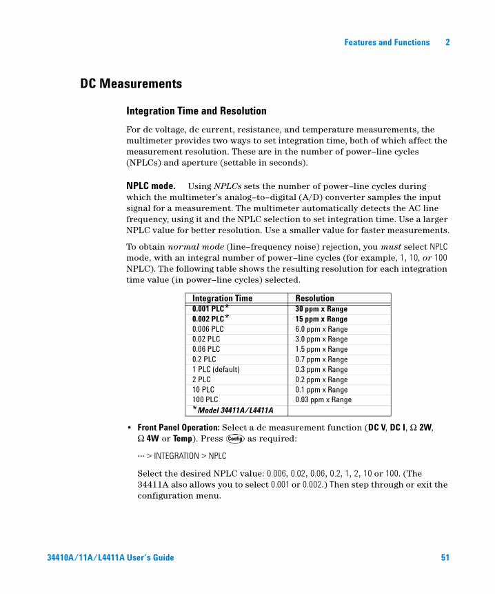
For dc voltage, dc current, resistance, and temperature measurements, the multimeter provides two ways to set integration time, both of which affect the measurement resolution. These are in the number of power–line cycles (NPLCs) and aperture (settable in seconds).
NPLC mode. Using NPLCs sets the number of power–line cycles during which the multimeter’s analog–to–digital (A/D) converter samples the input signal for a measurement. The multimeter automatically detects the AC line frequency, using it and the NPLC selection to set integration time. Use a larger NPLC value for better resolution. Use a smaller value for faster measurements.
To obtain normal mode (line–frequency noise) rejection, you must select NPLC mode, with an integral number of power–line cycles (for example, 1, 10, or 100 NPLC). The following table shows the resulting resolution for each integration time value (in power–line cycles) selected.
• Front Panel Operation: Select a dc measurement function (DC V, DC I, Ω 2W, Ω 4W or Temp). Press as required:
... > INTEGRATION > NPLC
Select the desired NPLC value: 0.006, 0.02, 0.06, 0.2, 1, 2, 10 or 100. (The 34411A also allows you to select 0.001 or 0.002.) Then step through or exit the configuration menu.
Integration Time Resolution0.001 PLC* 30 ppm x Range0.002 PLC* 15 ppm x Range0.006 PLC 6.0 ppm x Range0.02 PLC 3.0 ppm x Range0.06 PLC 1.5 ppm x Range0.2 PLC 0.7 ppm x Range1 PLC (default) 0.3 ppm x Range2 PLC 0.2 ppm x Range10 PLC 0.1 ppm x Range100 PLC 0.03 ppm x Range*Model 34411A/L4411A
34410A/11A/L4411A User’s Guide 51
2 Features and Functions
• Remote Interface Operation: The following commands set the integration time in NPLC:[SENSe:]VOLTage[:DC]:NPLC <PLCs>>MIN>MAX>DEF[SENSe:]CURRent[:DC]:NPLC <PLCs>>MIN>MAX>DEF[SENSe:]RESistance:NPLC <PLCs>>MIN>MAX>DEF[SENSe:]FRESistance:NPLC <PLCs>>MIN>MAX>DEF[SENSe:]TEMPerature:NPLC <PLCs>>MIN>MAX>DEF
Each of these commands also has a query form.
Refer to the Agilent 34410A/11A/L4411A Programmer’s Reference Help for a complete description and syntax for these commands.
Aperture mode. Aperture is the period, measured in seconds, during which the multimeter’s analog–to–digital (A/D) converter samples the input signal for a measurement. A longer aperture yields better resolution; a shorter aperture provides for faster measurements. This mode allows the user to set a specific integration time, not based on power–line frequency. Values range from 100 µs to 1 second for the 34410A, and from 20 µs to 1 second for the 34411A/L4411A.
• To allow for normal mode (line frequency noise) rejection, select the NPLC option for INTEGRATION, with an integral number of NPLCs. Use the APERTURE method only if you need precise control over the multimeter’s integration time, in seconds.
• Front Panel Operation: Select a dc measurement function (DC V, DC I, Ω 2W, Ω 4W or Temp). Press as required:
... > INTEGRATION > APERTURE
Use the navigation keypad to set the desired aperture value, and press . Then step through or exit the configuration menu.
• Remote Interface Operation: The following commands set the aperture value, in seconds:[SENSe:]VOLTage[:DC]:APERture <seconds>>MIN>MAX>DEF[SENSe:]CURRent[:DC]:APERture <seconds>>MIN>MAX>DEF[SENSe:]RESistance:APERture <seconds>>MIN>MAX>DEF[SENSe:]FRESistance:APERture <seconds>>MIN>MAX>DEF[SENSe:]TEMPerature:APERture <seconds>>MIN>MAX>DEF
Each of these commands also has a query form.
52 34410A/11A/L4411A User’s Guide
Features and Functions 2
The following command (similar queries for current, resistance and temperature) returns whether aperture mode is enabled:
[SENSe:]VOLTage[:DC]:APERture:ENABled?
This query returns a “0” (disabled) or “1” (enabled).
Refer to the Agilent 34410A/11A/L4411A Programmer’s Reference Help for a complete description and syntax for these commands.
DC Input Impedance
Applies to dc voltage measurements only.
The default setting for the multimeter’s input impedance is fixed at 10 MΩ for all dc voltage ranges, to minimize noise pickup. To reduce the effects of measurement loading errors when making low–voltage measurements, this fixed resistance can be set to HI–Z (>10 GΩ) for the 100 mVdc, 1 Vdc, and 10 Vdc ranges.
• Front Panel Operation: After the function is selected, press .
INTEGRATION > RANGE > INPUT Z
Select 10 M or HI–Z, and then step through or exit the menu.
Note that when HI–Z is selected, the multimeter will set an input impedance of >10 GΩ for the three lowest dc voltage ranges. The input impedance remains 10 MΩ for all measurement ranges above 10 Vdc.
• Remote Interface Operation: The following command turns on the auto input impedance function for dc voltage measurements. The AUTO function (equivalent of setting HI–Z from the front panel) uses 10 MΩ for the 100V and 1000V ranges, and >10 GΩ for the 100 mVdc, 1 Vdc and 10 Vdc ranges.[SENSe:]VOLTage:DC:IMPedance:AUTO OFF>0>ON>1
The following command queries the auto impedance function setting:[SENSe:]VOLTage:DC:IMPedance:AUTO?This query returns a “0” (OFF) or “1” (ON).
Refer to the Agilent 34410A/11A/L4411A Programmer’s Reference Help for a complete description and syntax for these commands.
34410A/11A/L4411A User’s Guide 53
2 Features and Functions
AC Measurements
AC Filter
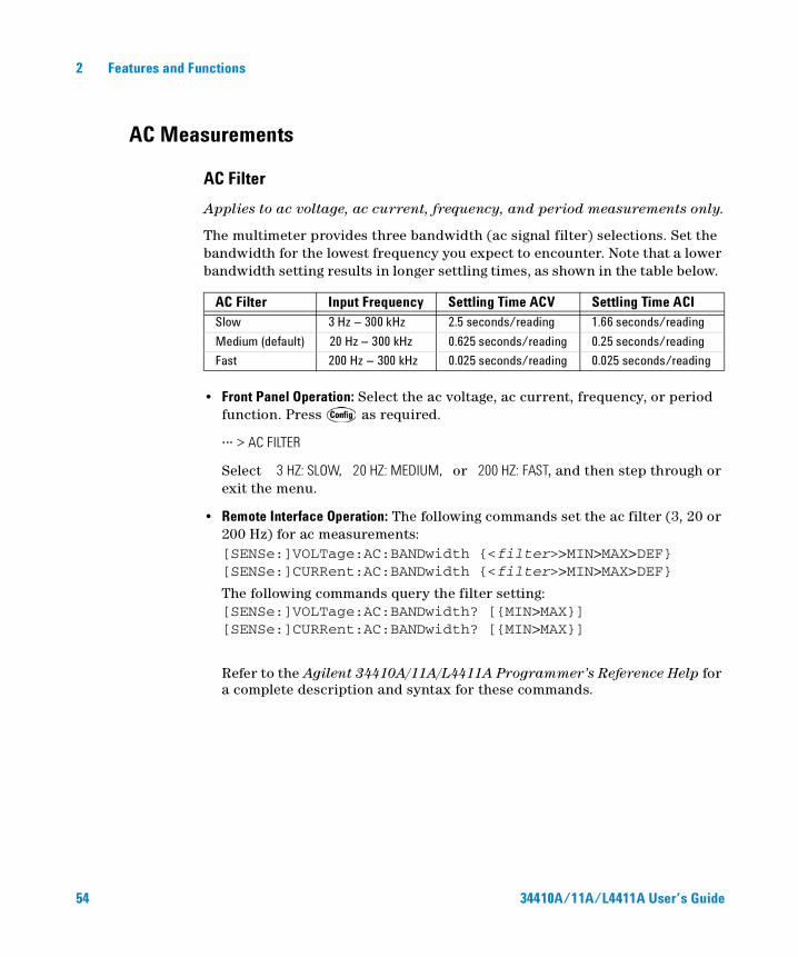
Applies to ac voltage, ac current, frequency, and period measurements only.
The multimeter provides three bandwidth (ac signal filter) selections. Set the bandwidth for the lowest frequency you expect to encounter. Note that a lower bandwidth setting results in longer settling times, as shown in the table below.
• Front Panel Operation: Select the ac voltage, ac current, frequency, or period function. Press as required.
... > AC FILTER
Select 3 HZ: SLOW, 20 HZ: MEDIUM, or 200 HZ: FAST, and then step through or exit the menu.
• Remote Interface Operation: The following commands set the ac filter (3, 20 or 200 Hz) for ac measurements:[SENSe:]VOLTage:AC:BANDwidth <filter>>MIN>MAX>DEF[SENSe:]CURRent:AC:BANDwidth <filter>>MIN>MAX>DEF
The following commands query the filter setting:[SENSe:]VOLTage:AC:BANDwidth? [MIN>MAX][SENSe:]CURRent:AC:BANDwidth? [MIN>MAX]
Refer to the Agilent 34410A/11A/L4411A Programmer’s Reference Help for a complete description and syntax for these commands.
AC Filter Input Frequency Settling Time ACV Settling Time ACISlow 3 Hz – 300 kHz 2.5 seconds/reading 1.66 seconds/reading
Medium (default) 20 Hz – 300 kHz 0.625 seconds/reading 0.25 seconds/reading
Fast 200 Hz – 300 kHz 0.025 seconds/reading 0.025 seconds/reading
54 34410A/11A/L4411A User’s Guide
Features and Functions 2
Gate Time
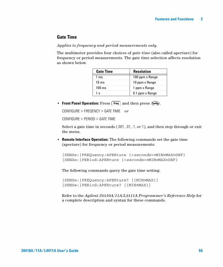
Applies to frequency and period measurements only.
The multimeter provides four choices of gate time (also called aperture) for frequency or period measurements. The gate time selection affects resolution as shown below.
• Front Panel Operation: Press and then press .
CONFIGURE > FREQENCY > GATE TIME or
CONFIGURE > PERIOD > GATE TIME
Select a gate time in seconds (.001, .01, .1, or 1), and then step through or exit the menu.
• Remote Interface Operation: The following commands set the gate time (aperture) for frequency or period measurements:
[SENSe:]FREQuency:APERture <seconds>>MIN>MAX>DEF[SENSe:]PERiod:APERture <seconds>>MIN>MAX>DEF
The following commands query the gate time setting:
[SENSe:]FREQuency:APERture? [MIN>MAX][SENSe:]PERiod:APERture? [MIN>MAX]
Refer to the Agilent 34410A/11A/L4411A Programmer’s Reference Help for a complete description and syntax for these commands.
Gate Time Resolution1 ms 100 ppm x Range
10 ms 10 ppm x Range
100 ms 1 ppm x Range
1 s 0.1 ppm x Range
34410A/11A/L4411A User’s Guide 55
2 Features and Functions
Auto Zero
Auto zero is selectable for dc voltage, dc current, 2–wire resistance, and 2-wire temperature measurements only. Auto zero is always enabled for 4–wire resistance or 4–wire temperature measurements.
When auto zero is ON (default) the multimeter internally disconnects the input signal immediately following each measurement, and takes a zero reading. It then subtracts the zero reading from the preceding measurement. This method prevents small offset voltages present on the multimeter’s input circuitry from affecting measurement accuracy.
When auto zero is OFF, the multimeter takes one zero reading and subtracts it from all subsequent measurements. A new zero reading is taken each time you change the function, range or resolution (integration time).
When auto zero is set to ONCE, the multimeter takes one zero reading, then sets auto zero to OFF. The zero reading taken is used for all subsequent measurements until the next change to the function, range or integration time. If the selected integration time is less than 1 PLC, the zero reading is taken at 1 PLC to ensure normal mode noise rejection in the zero reading; then subsequent readings are taken at the set integration time.
• Front Panel Operation: Select a supported function. Press as required.
... > AUTO ZERO
Select OFF, ONCE, or ON, and then step through or exit the menu.
• Remote Interface Operation: The following command enables or disables auto zero: SENSe:<function>:ZERO:AUTO OFF>ONCE>0>ON>1
where <function> = VOLTage:DC, CURRent:DC, RESistance, or TEMPerature.
Auto zero may be also set indirectly using the CONFigure or MEASure commands.
The following command queries the auto zero feature status:
SENSe:<function>:ZERO:AUTO?
This query command returns “0” (OFF) or “1” (ON).
Refer to the Agilent 34410A/11A/L4411A Programmer’s Reference Help for a complete description and syntax for these commands.
56 34410A/11A/L4411A User’s Guide

Features and Functions 2
Ranging
Applies to all measurements except continuity and diode test, which use a fixed range. Temperature measurements always use autoranging.
You can let the multimeter automatically select the range using autoranging, or you can select a fixed range using manual ranging. Autoranging is convenient because the multimeter automatically selects the appropriate range for sensing and displaying each measurement. However, manual ranging results in better performance, since the multimeter does not have to determine which range to use for each measurement.
• Autorange thresholds – The multimeter will shift range as follows:Down range at <10% of present rangeUp range at >120% of present range
• Ranging is local to the selected function; the multimeter remembers the selected ranging method (auto or manual) and selected manual range when you switch between measurement functions.
• For frequency and period measurements, the selected range is for the ac voltage level of the input signal.
• For temperature measurements, the multimeter uses autoranging, as appropriate for the probe type.
• For continuity tests, the multimeter range is fixed at 1 kΩ. For diode tests the range is fixed at 1 Vdc with a 1 mA current source output.
• Front Panel Operation: For applicable measurement functions, the ranging method and manual range may be selected by front panel shortcuts (see “Ranging.” on page 42).
Or, use the configuration menu for the selected function. For the latter method. Press as required:
... > RANGE > AUTO or
... > RANGE > MANUAL (select the desired range.)
Then step through or exit the menu.
For manual ranging: If the input signal is greater than can be measured on the selected range, the multimeter provides these overload indications: ± OVLD from the front panel or “±9.9E+37” from the remote interface. (The sign is ± or +, whichever is appropriate.)
34410A/11A/L4411A User’s Guide 57
2 Features and Functions
• Remote Interface Operation: Autoranging may be enabled or disabled for the specified function using the following command: SENSe:<function>:RANGe:AUTO OFF>ONCE>0>ON>1
where <function> = VOLTage:DC, VOLTage:AC, CURRent:DC, CURRent:AC, RESistance, FRESistance, or CAPacitance.
For <function> = FREQuency or PERiod, the range commands affect the ac signal input voltage range.
The following command queries the autoranging feature status for the specified <function>:SENSe:<function>:RANGe:AUTO?
This query command returns “0” (OFF) or “1” (ON).
The following command manually sets the multimeter range for the specified <function>:SENSe:<function>:RANGe[:UPPER] <range>>MIN>MAX>DEF
A manual range may also be set using the CONFigure or MEASure commands.
The following command queries the multimeter range setting for the specified <function>:SENSe:<function>:RANGe[:UPPER]? [MIN>MAX]
Refer to the Agilent 34410A/11A/L4411A Programmer’s Reference Help for a complete description and syntax for all commands on this page.
A Word About Ranging and Digits. The 34410A/11A/L4411A is capable of displaying “6½ digits” for most measurements. The crossover is at a 20 percent overload for the currently selected range. Let’s look at an example for dc voltage with autoranging enabled. As the input voltage increases from just below 1 volt to just above 1.2 volts, you might see the following progression of readings on the front-panel display:
0.997,385 VDC1.000,544 VDC1.099,004 VDC1.190,188 VDC0.120,013 VDC
58 34410A/11A/L4411A User’s Guide
Features and Functions 2
The first four readings are taken on the 1 Vdc range, but the autoranging feature switches to the 10 Vdc range for the final reading, which is a 20 percent overload for the 1 Vdc range. This is a typical 6½ digit behavior.
For frequency measurements only, the 34410A/11A/L4411A is capable of displaying a full seven digits (for example, “999.980,3 HZ”).
Null Measurements
The 34410A/11A/L4411A allows separate null settings to be saved for each of the following measurement functions: dc voltage, ac voltage, dc current, ac current, resistance, frequency/period, capacitance, and temperature.
When making null (also called relative) measurements, each reading is the difference between a stored (selected or measured) null value and the input signal. One possible application is to increase accuracy of two–wire resistance measurements by nulling the test lead resistance. Nulling the leads is particularly important prior to making capacitance measurements. The formula used for calculating null measurements is:
Result = reading – null value
• The null value is adjustable, and you can set it to any value between 0 and ±120% of the highest range, for the present function. Note that the null value is entered in fundamental units (for example, Vdc).
• Front Panel Operation: For any measurement function, you can directly measure and store the null value by pressing with the test leads open (nulls the test lead capacitance), shorted (nulls the test lead resistance), or across a desired null value circuit.
Alternately, you can enable null from the menu. Press as required:
... > NULL > ON > NULL VALUE
Enter the desired null value with the navigation keypad, and then step through or exit the menu. The Null annunciator is lit and the null function is enabled.
To turn the null function off: Press again, or use the menu.
• Remote Interface Operation: The following command enables the null measurement feature for the specified function:SENSe:<function>:NULL[:STATe] ON>OFF
where <function> is any function except CONTinuity or DIODe.
34410A/11A/L4411A User’s Guide 59
2 Features and Functions
The following command queries the null measurement feature setting:SENSe:<function>:NULL[:STATe]?This query returns a “0” (OFF) or “1” (ON).
The following command stores a null value for the specified function:SENSe:<function>:NULL[:VALue] <value>>MIN>MAX
The following command queries the null value:SENSe:<function>:NULL[:VALue]?
Refer to the Agilent 34410A/11A/L4411A Programmer’s Reference Help for a complete description and syntax for these commands.
Miscellaneous Configuration Settings
Radix Character (34410A/11A)
Available from the front panel only. The multimeter can display the radix character (decimal point) as a period or a comma.
• The factory (default) setting is PERIOD.
• The radix character setting is stored in non–volatile memory.
• Front Panel Operation: Press
UTILITY MENU > MISC SETTINGS > BEEPER > RADIX CHAR
Select PERIOD or COMMA, and then step through or exit the menu.
Thousands Separator (34410A/11A)
Available from the front panel only. The multimeter can display front panel readings with (ON) or without (OFF) a comma (thousands separator) delimiting the number into 3–digit sets.
• The factory (default) setting is ON.
• Front Panel Operation: Press
UTILITY MENU > MISC SETTINGS > BEEPER > RADIX CHAR > THOUSAND SEP
Select OFF or ON, and then step through or exit the menu.
60 34410A/11A/L4411A User’s Guide
Features and Functions 2
Beeper (34410A/11A)
Normally, the multimeter emits a tone from the front panel whenever certain conditions are met (for example, the multimeter beeps when a stable reading is captured in reading hold mode). The beeper is factory set to ON, but may be disabled or enabled manually.
• Turning off the beeper does not disable the key click generated when you press a front–panel key.
• A beep tone is always emitted (even with the beep state turned OFF) in the following cases.
• A continuity measurement is less than or equal to the continuity threshold.
• A SYSTem:BEEPer command is sent.
• A beep tone is emitted only if the beep state is ON in the following cases.
• An error is generated.
• A set LO or HI limit is exceeded in a limit test.
• A stable reading is captured in the reading hold mode.
• A forward-biased diode is measured in the diode test function.
• Front Panel Operation: Press
UTILITY MENU > MISC SETTINGS > BEEPER
Select OFF or ON, and then step through or exit the menu.
• Remote Interface Operation: The following command disables or enables the front panel beeper:SYSTem:BEEPer:STATe OFF>0>ON>1
The following command queries the state of the beeper:SYSTem:BEEPer:STATe?This query returns a “0” (OFF) or “1” (ON).
Refer to the Agilent 34410A/11A/L4411A Programmer’s Reference Help for a complete description and syntax for these commands.
34410A/11A/L4411A User’s Guide 61
2 Features and Functions
Math Functions
In addition to providing a separate null–per–function measurement capability, the multimeter provides four math functions: dB measurements (dB), dBm measurements (dBm), statistics for accumulated readings (STATS), and limit testing (LIMITS). Only one of these math functions can be enabled at a time (in addition to the null measurement), and remains in effect until you turn it off or change it.
• Front Panel Operation: Press
MATH Select: OFF, dB, dBm, STATS or LIMITS.
See the dB, dBm, statistics, and limit testing sections that follow.
To turn any math function off: Press
MATH > OFF
• Remote Interface Operation: The following command selects the math function to be used:CALCulate:FUNCtion NULL>DB>DBM>AVERage>LIMit
The following command queries the currently selected math function:CALCulate:FUNCtion?
This query returns the currently selected function
The following command turns the CALCulate subsystem, and thus all math functions, on or off:CALCulate[:STATe] OFF>ON
The following command queries the current calculation state:CALCulate:STATe?This query returns a “0” (OFF) or a “1” (ON).
Refer to the Agilent 34410A/11A/L4411A Programmer’s Reference Help for a complete description and syntax for these commands.
NOTE The null function in the CALCulate:FUNCtion command is provided only for SCPI compatibility with the 34401A Multimeter. This null is not available from the front panel. The use of this null is deprecated for the 34410A/11A/L4411A. Use the null-per-function commands found in the [SENSe:] subsystem instead. See “Null Measurements” on page 59 and the Agilent 34410A/11A/L4411A Programmer’s Reference Help for details.
62 34410A/11A/L4411A User’s Guide
Features and Functions 2
dB Measurements
Applies to ac voltage and dc voltage measurements only.
Each dB measurement is the difference between the input signal and a stored relative value, with both values converted to dBm.
dB = reading in dBm – relative value in dBm
• The relative value can take any value between 0 dBm and ± 200.0 dBm. The default relative value is 0 dBm. You can either let the instrument automatically measure this value, or you can enter a specified value.
• Front Panel Operation: Press
MATH > dB > dB RELATIVE
Select MEASURE or VALUE.
• Select MEASURE if you want the instrument to set the relative value automatically by measurement. The Math annunciator will light and the reading will be displayed in dB.
If the configured settings will result in a long measurement time or have the multimeter waiting for an external trigger, the Math annunciator will flash until the relative value measurement is taken.
• Select VALUE if you want to enter a specific relative value. Use the navigation keypad to set the desired dB REL VALUE. The Math annunciator will light and the reading will be displayed in dB.
You can also select VALUE to view a previously set or measured value.
• Remote Interface Operation: The following command sequence selects the dB function, turns the function on, and sets a relative value.CALCulate:FUNCtion DBCALCulate:STATe ONCALCulate:DB:REFerence <value>
Refer to the Agilent 34410A/11A/L4411A Programmer’s Reference Help for a complete description and syntax for these commands.
34410A/11A/L4411A User’s Guide 63
2 Features and Functions
dBm Measurements
Applies to ac voltage and dc voltage measurements only.
The dBm function is logarithmic, and is based on a calculation of power delivered to a reference resistance, relative to 1 milliwatt.
dBm = 10 x log10 (reading 2 / reference resistance / 1 mW )
• You can choose from several reference resistance values: 50, 75, 93, 110, 124, 125, 135, 150, 250, 300, 500, 600, 800, 900, 1000, 1200, or 8000 (ohms). The default setting is 600 ohms.
• Front Panel Operation: Press
MATH > dBM > dBm REF R
Select the desired reference resistance. The Math annunciator turns on and the reading is now displayed in dBm.
• Remote Interface Operation: The following command sequence selects the dBm function, turns the function on, and sets the reference resistance.CALCulate:FUNCtion DBMCALCulate:STATe ONCALCulate:DBM:REFerence <value>
Refer to the Agilent 34410A/11A/L4411A Programmer’s Reference Help for a complete description and syntax for these commands.
64 34410A/11A/L4411A User’s Guide
Features and Functions 2
Using Statistics
Applies to all measurement functions except continuity and diode test.
From the front panel, you can view the following statistical data for any set of readings: average or mean (AVG), maximum (MAX), minimum (MIN), standard deviation (SDEV), and number of samples taken (COUNT). From the remote interface you can read all of these, plus the peak–to–peak (MAX – MIN) value.
• Front Panel Operation: Press
MATH > STATS
Scroll the second display with the and keys to view the statistical data AVG, MAX, MIN, SDEV and COUNT.
• Remote Interface Operation: The following command enables the statistics function:CALCulate:FUNCtion AVERage
The following queries return the mean, minimum value, maximum value, standard deviation, peak–to–peak value, and number of readings, respectively, since statistics were enabled or cleared.CALCulate:AVERage:AVERage?
CALCulate:AVERage:MINimum?CALCulate:AVERage:MAXimum?CALCulate:AVERage:SDEViation?CALCulate:AVERage:PTPeak?CALCulate:AVERage:COUNt?
Refer to the Agilent 34410A/11A/L4411A Programmer’s Reference Help for a complete description and syntax for these commands.
NOTE The stored statistical data are cleared when statistics are enabled, when the CALCulate:FUNCtion command is sent while CALCulate:STATe is ON, when the power has been off, when the CALCulate:AVERage:CLEar command is executed, after a Factory Reset (*RST command), after an Instrument Preset (SYSTem:PRESet command), or after a function change.
34410A/11A/L4411A User’s Guide 65
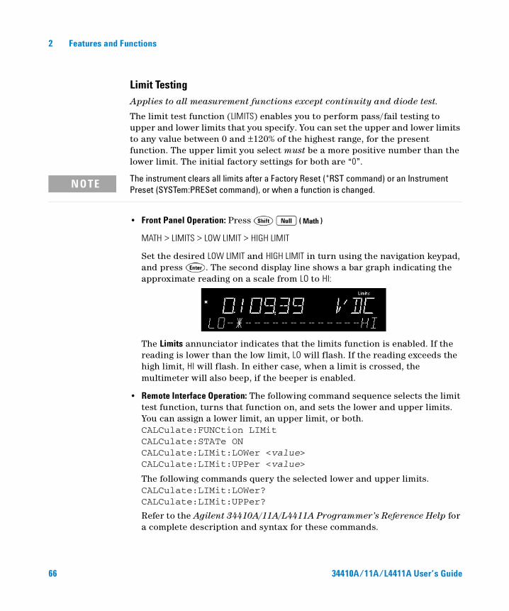
2 Features and Functions
Limit Testing
Applies to all measurement functions except continuity and diode test.
The limit test function (LIMITS) enables you to perform pass/fail testing to upper and lower limits that you specify. You can set the upper and lower limits to any value between 0 and ±120% of the highest range, for the present function. The upper limit you select must be a more positive number than the lower limit. The initial factory settings for both are “0”.
• Front Panel Operation: Press
MATH > LIMITS > LOW LIMIT > HIGH LIMIT
Set the desired LOW LIMIT and HIGH LIMIT in turn using the navigation keypad, and press . The second display line shows a bar graph indicating the approximate reading on a scale from LO to HI:
The Limits annunciator indicates that the limits function is enabled. If the reading is lower than the low limit, LO will flash. If the reading exceeds the high limit, HI will flash. In either case, when a limit is crossed, the multimeter will also beep, if the beeper is enabled.
• Remote Interface Operation: The following command sequence selects the limit test function, turns that function on, and sets the lower and upper limits. You can assign a lower limit, an upper limit, or both.CALCulate:FUNCtion LIMitCALCulate:STATe ONCALCulate:LIMit:LOWer <value>CALCulate:LIMit:UPPer <value>
The following commands query the selected lower and upper limits.CALCulate:LIMit:LOWer?CALCulate:LIMit:UPPer?
Refer to the Agilent 34410A/11A/L4411A Programmer’s Reference Help for a complete description and syntax for these commands.
NOTE The instrument clears all limits after a Factory Reset (*RST command) or an Instrument Preset (SYSTem:PRESet command), or when a function is changed.
66 34410A/11A/L4411A User’s Guide
Features and Functions 2
Triggering the MultimeterThe 34410A/11A/L4411A triggering system allows you to generate triggers either manually or automatically, take multiple readings per trigger, and insert a delay before each reading. The 34411A/L4411A also allows you to set a level for internal triggering, and to set up pre-triggering.
Selecting a Trigger SourceSpecify the source from which the multimeter will accept a trigger. The power–on default is auto triggering from the front panel. Several types of triggering are described in the sections that follow.
• Front Panel Operation:
• Press once to go to the single trigger mode. A single reading is taken, and another reading is taken each time you press , or when a hardware trigger is received on the Ext Trig connector.
• Press and select:
TRIGGER > AUTO To return to auto trigger mode.
TRIGGER > LEVEL To select internal (level) triggering (34411A only).
TRIGGER > HOLD To select reading hold mode.
TRIGGER > SETUP To enter the trigger setup menu.
• Remote Interface Operation: The following command selects the trigger source from the remote interface:TRIGger:SOURce IMMediate>EXTernal|BUS>INTernal
Where INTernal triggering applies only to the 34411A/L4411A.
Refer to the Agilent 34410A/11A/L4411A Programmer’s Reference Help for a complete description and syntax for this command.
34410A/11A/L4411A User’s Guide 67
2 Features and Functions
Auto Triggering (34410A/11A)
This mode is available from the front panel only.
The power–on trigger default mode for the multimeter is front panel operation, in auto trigger mode.
• Auto triggering takes continuous readings at the fastest rate possible for the specified measurement configuration (function, range, resolution, and so forth).
• Auto triggering is a front panel mode similar to immediate triggering from the remote interface, but also sets the sample count to infinite and automatically initiates continuous measurements.
• To enable auto triggering, press
TRIGGER > AUTO
Single Triggering (34410A/11A)
This mode is available from the front panel only.
• The multimeter takes one reading, or a number of readings specified by a sample count you enter, each time you press , or upon receiving an external trigger signal on the rear-panel Ext Trig connector (see “External Triggering” on page 75). See also “Number of Samples per Trigger” on page 71.
• The Trig annunciator indicates that the multimeter is waiting for a trigger.
68 34410A/11A/L4411A User’s Guide
Features and Functions 2
Reading Hold (34410A/11A)
This mode is available from the front panel only.
The reading hold mode allows you to capture and hold a stable reading on the front panel display. This is useful in situations when you want to take a reading, remove the test probes, and have the reading remain on the display. When a stable reading is detected, the multimeter emits a beep (if the front–panel beeper is enabled) and holds the reading on the display.
• The sensitivity band for reading hold depends on the measurement function that is selected. The multimeter captures and displays a new value only when reading stability is detected.
• Reading hold is disabled if you change measurement functions, or if you change to remote mode.
• The currently configured range (auto or manual) is used for reading hold. If you manually select a new range, reading hold is disabled.
• To enable reading hold, press
TRIGGER > HOLD
• The Hold annunciator is lit.
• Each time a stable reading is detected, the reading is displayed and the beeper sounds (if enabled).
Immediate TriggeringThis mode is available from the remote interface only.
In the immediate trigger mode, the trigger signal is always present. When you place the multimeter in the wait–for–trigger state, the trigger is issued immediately. This is the default trigger source for remote interface operation.
• Remote Interface Operation: The following command selects the immediate trigger source:TRIGger:SOURce IMMediate
The CONFigure and MEASure? commands automatically set the trigger source to IMMediate.
Refer to the Agilent 34410A/11A/L4411A Programmer’s Reference Help for a complete description and syntax for these commands.
34410A/11A/L4411A User’s Guide 69
2 Features and Functions
Software (Bus) Triggering
This mode is available from the remote interface only.
The bus trigger mode corresponds in function to pressing the key from the front panel, except that the trigger is initiated by sending a bus trigger command, after selecting BUS as the trigger source.
• The following command selects the bus trigger source:
TRIGger:SOURce BUS
Then, any of the following commands will initiate readings:MEASure?READ?
INITiate
Refer to the Agilent 34410A/11A/L4411A Programmer’s Reference Help for a complete description and syntax for these commands.
Internal (Level) Triggering (34411A/L4411A)
Applies only to ac and dc voltage, ac and dc current, and 2-wire and 4-wire resistance measurements, and only for the 34411A/L4411A.
In the internal trigger mode, the 34411A/L4411A triggers on a positive or negative crossing (as selected) of a specified input level. You can specify both the trigger level, and the slope.
• Front Panel Operation: Press
TRIGGER > LEVEL > TRIG LEVEL > TRIG SLOPE
Set TRIG LEVEL with the navigation keys, and then select NEG or POS for TRIG SLOPE. The Trig annunciator indicates “waiting for trigger”.
• Remote Interface Operation: The following command selects the internal trigger source:TRIGger:SOURce INTernal
The following command sets the trigger level on which to trigger:TRIGger:LEVel <level>
The following command sets the trigger slope (positive or negative):TRIGger:SLOPe POS|NEG
Refer to the Agilent 34410A/11A/L4411A Programmer’s Reference Help for a complete description and syntax for these commands.
70 34410A/11A/L4411A User’s Guide
Features and Functions 2
Number of Samples per Trigger
By default, when the multimeter is in the wait–for–trigger state, it takes one reading (or sample) each time you trigger the multimeter. You can, however, instruct the multimeter to take up to 50,000 readings (up to 1 million for the 34411A/L4411A) each time a trigger is initiated, whether from the front panel or remote interface.
• Front Panel Operation: Press
TRIGGER > SETUP > N SAMPLES
Enter the desired number of samples per trigger using the navigation keypad, and then step through or exit the menu.
• Remote Interface Operation: The following command selects the number of samples the multimeter will take per trigger:
SAMPle:COUNt <count>>MIN>MAX
After setting the sample count, you must place the meter in the wait–for–trigger state before readings are triggered (see “Software (Bus) Triggering” on page 70).
Refer to the Agilent 34410A/11A/L4411A Programmer’s Reference Help for a complete description and syntax for this command.
Number of Pre-Trigger Samples (34411A/L4411A)
The 34411A and L4411A provide pre-triggering. This feature allows you to specify a pre-trigger sample count of readings to be retained before the trigger is received. The pre–trigger sample count must be less than the sample count. Pre–triggering is primarily a remote interface function, and is described more completely in the Agilent 34410A/11A/L4411A Programmer’s Reference Help. However, you can set the pre–trigger count from the front panel, and you can use pre–triggering with the Data Logger feature (see “Data Logging” on page 78). Pre-triggering is not supported for continuity or diode test.
• Front Panel Operation: Press
TRIGGER > SETUP > N SAMPLES > PRE-TRIG CNT
Enter the desired number of pre–trigger samples per trigger using the navigation keypad, and then step through or exit the menu. (The PRE-TRIG CNT selection appears only if N SAMPLES is greater than one.)
34410A/11A/L4411A User’s Guide 71
2 Features and Functions
• Remote Interface Operation: The following commands set the sample count (must be >1) and pre–trigger sample count:
SAMPle:COUNt <count>|MIN|MAX|DEF
SAMPle:COUNt:PRETrigger <PTcount>>MIN>MAX|DEF
Refer to the Agilent 34410A/11A/L4411A Programmer’s Reference Help for a complete description and syntax for this command.
Trigger Delay
You can manually specify a delay between the trigger signal and the first sample that follows. This may be useful in applications where you want to allow the input signal to settle before taking a reading, or for pacing a burst of readings.
• The trigger delay may be set from 0 to 3600 seconds.
• The continuity and diode test functions ignore the trigger delay setting.
• If a trigger delay is not manually set, the default trigger delay is automatically set, based on function, range, integration time and/or ac filter setting (see also “Automatic Trigger Delay” on page 73).
• If you manually specify a trigger delay, that delay is used for all measurement functions (except continuity and diode test).
• Front Panel Operation: Press
TRIGGER > SETUP > N SAMPLES > PRE-TRIG CNT > TRIG DELAY
Select AUTO, ZERO, or MANUAL:
• Select AUTO to use the automatic trigger delay.
• Select ZERO for a zero delay.
• Select MANUAL to enter the desired delay using the navigation keypad.
Then step through or exit the menu.
• Remote Interface Operation: The following command specifies the trigger delay, in seconds:TRIGger:DELay <seconds>>MIN>MAX
The following command specifies the automatic trigger delay:TRIGger:DELay:AUTO
72 34410A/11A/L4411A User’s Guide
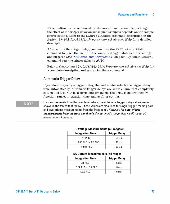
Features and Functions 2
If the multimeter is configured to take more than one sample per trigger, the effect of the trigger delay on subsequent samples depends on the sample source setting. Refer to the SAMPle:SOURce command description in the Agilent 34410A/11A/L4411A Programmer’s Reference Help for a detailed description.
After setting the trigger delay, you must use the INITiate or READ command to place the meter in the wait–for–trigger state before readings are triggered (see “Software (Bus) Triggering” on page 70). The MEASure? command sets the trigger delay to AUTO.
Refer to the Agilent 34410A/11A/L4411A Programmer’s Reference Help for a complete description and syntax for these command.
Automatic Trigger Delay
If you do not specify a trigger delay, the multimeter selects the trigger delay time automatically. Automatic trigger delays are set to ensure that completely settled and accurate measurements are taken. The delay is determined by function, range, integration time, and ac filter setting.
DC Voltage Measurements (all ranges):
DC Current Measurements (all ranges):
NOTE For measurements from the remote interface, the automatic trigger delay values are as shown in the tables that follow. These values are also used for single-trigger, reading-hold, and level-trigger measurements from the front panel. However, for auto-trigger measurements from the front panel only, the automatic trigger delay is 50 ms for all measurement functions.
Integration Time Trigger Delay
≥1 PLC 160 µs
0.06 PLC or 0.2 PLC 130 µs
≤0.02 PLC 100 µs
Integration Time Trigger Delay
≥1 PLC 1.5 ms
0.06 PLC or 0.2 PLC 1.0 ms
≤0.2 PLC 1.0 ms
34410A/11A/L4411A User’s Guide 73
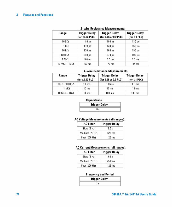
2 Features and Functions
2–wire Resistance Measurements:
4–wire Resistance Measurements
Capacitance
AC Voltage Measurements (all ranges):
AC Current Measurements (all ranges):
Frequency and Period
Range Trigger Delay(for ≤0.02 PLC)
Trigger Delay(for 0.06 or 0.2 PLC)
Trigger Delay (for ≥1 PLC)
100 Ω 80 µs 100 µs 130 µs
1 kΩ 110 µs 130 µs 160 µs
10 kΩ 130 µs 160 µs 190 µs
100 kΩ 540 µs 670 µs 800 µs
1 MΩ 5.0 ms 6.0 ms 7.5 ms
10 MΩ – 1GΩ 60 ms 70 ms 84 ms
Range Trigger Delay(for ≤0.02 PLC)
Trigger Delay(for 0.06 or 0.2 PLC)
Trigger Delay (for ≥1 PLC)
100Ω – 100 kΩ 1.0 ms 1.0 ms 1.5 ms
1 MΩ 10 ms 10 ms 15 ms
10 MΩ – 1GΩ 100 ms 100 ms 100 ms
Trigger Delay
0 s
AC Filter Trigger Delay
Slow (3 Hz) 2.5 s
Medium (20 Hz) 625 ms
Fast (200 Hz) 25 ms
AC Filter Trigger Delay
Slow (3 Hz) 1.66 s
Medium (20 Hz) 250 ms
Fast (200 Hz) 25 ms
Trigger Delay
1 s
74 34410A/11A/L4411A User’s Guide
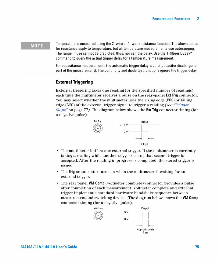
Features and Functions 2
External Triggering
External triggering takes one reading (or the specified number of readings) each time the multimeter receives a pulse on the rear–panel Ext Trig connector. You may select whether the multimeter uses the rising edge (POS) or falling edge (NEG) of the external trigger signal to trigger a reading (see “Trigger Slope” on page 77). The diagram below shows the Ext Trig connector timing (for a negative pulse).
• The multimeter buffers one external trigger. If the multimeter is currently taking a reading while another trigger occurs, that second trigger is accepted. After the reading in progress is completed, the stored trigger is issued.
• The Trig annunciator turns on when the multimeter is waiting for an external trigger.
• The rear panel VM Comp (voltmeter complete) connector provides a pulse after completion of each measurement. Voltmeter complete and external trigger implement a standard hardware handshake sequence between measurement and switching devices. The diagram below shows the VM Comp connector timing (for a negative pulse).
NOTE Temperature is measured using the 2–wire or 4–wire resistance function. The above tables for resistance apply to temperature, but all temperature measurements use autoranging. The range in use cannot be predicted; thus, nor can the delay. Use the TRIGger:DELay? command to query the actual trigger delay for a temperature measurement.
For capacitance measurements the automatic trigger delay is zero (capacitor discharge is part of the measurement). The continuity and diode test functions ignore the trigger delay.
34410A/11A/L4411A User’s Guide 75
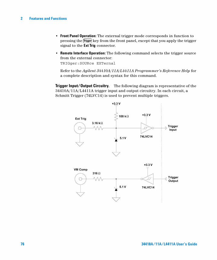
2 Features and Functions
• Front Panel Operation: The external trigger mode corresponds in function to pressing the key from the front panel, except that you apply the trigger signal to the Ext Trig connector.
• Remote Interface Operation: The following command selects the trigger source from the external connector:TRIGger:SOURce EXTernal
Refer to the Agilent 34410A/11A/L4411A Programmer’s Reference Help for a complete description and syntax for this command.
Trigger Input/Output Circuitry. The following diagram is representative of the 34410A/11A/L4411A trigger input and output circuitry. In each circuit, a Schmitt Trigger (74LVC14) is used to prevent multiple triggers.
76 34410A/11A/L4411A User’s Guide
Features and Functions 2
Trigger Slope
You may select whether the multimeter uses the rising edge (POS) or falling edge (NEG) of the external trigger signal to trigger a reading, or (independently) for the voltmeter complete output signal. The default for both is NEG.
• Front Panel Operation: Press
TRIGGER > SETUP > N SAMPLES > TRIG DELAY > TRIG SLOPE > VMC SLOPE
For each of TRIG SLOPE and VMC SLOPE, you can select either NEG or POS:
• TRIG SLOPE sets the slope of the Ext Trig input signal (NEG or POS).
• VMC SLOPE sets the slope of the VM Comp output signal (NEG or POS).
Then step through or exit the configuration menu.
• Remote Interface Operation: The following command selects the trigger slope for the external trigger (Ext Trig) connector:TRIGger:SLOPe POSitive>NEGative
The following query returns the selected trigger slope for the Ext Trig connector:TRIGger:SLOPe?
This query returns POS or NEG.
The following command selects the signal slope for the voltmeter complete (VM Comp) signal:OUTPut:TRIGger:SLOPe POSitive>NEGative
The following query returns the selected trigger slope for the VM Comp connector:OUTPut:TRIGger:SLOPe?
This query returns POS or NEG.
Refer to the Agilent 34410A/11A/L4411A Programmer’s Reference Help for a complete description and syntax for this command.
34410A/11A/L4411A User’s Guide 77
2 Features and Functions
Data LoggingThe Data Logger feature provides a front–panel user interface that allows you to set up data logging into the instrument’s non–volatile memory without programming, and without a connection to a computer. Once you have finished collecting data, you can view it from the front panel, or you can then connect your computer and import the data. The 34410A/11A/L4411A Web Interface provides a very convenient way of importing the data into your spreadsheet or other application.
The 34410A/11A/L4411A allows you to set the following data logging parameters: START DELAY, INTERVAL, EVENTS/TIME (COUNT or DURATION).
• START DELAY is the delay time (0 to 3600 seconds) after initiating a trigger, before the data logging function takes its first reading.
• INTERVAL is the time (20 µs to 3599.99999 s) between subsequent readings. The minimum interval is configuration dependent and may be greater than 20 µs.
• EVENTS/TIME is the total duration of the data logging session. You can set a COUNT of total readings, with N SAMPLES settable from 1 to 50,000 readings. Or, you can set a DURATION in hours, minutes and seconds. The maximum duration that you can set is limited to that which results in 50,000 readings, but in no event more than HH:MM:SS = 99:59:59 (just under 100 hours).
• Front Panel Operation: To set up a data logging session, press
DATA LOGGER > SETUP > START DELAY > INTERVAL > EVENTS/TIME
• For START DELAY, enter the desired delay (use the navigation keypad).
• For INTERVAL, enter the desired interval.
• For EVENTS/TIME, select either COUNT or DURATION. Select COUNT if you want to enter a total sample count. Select DURATION if you want to enter a time duration.
• Upon pressing , the message TO START - PRESS TRIGGER KEY appears. The data logger is now ready to go. Just press to begin logging. (A trigger pulse on the Ext Trig connector will also initiate the session.)
NOTE The Data Logger logs data to non-volatile memory. Once the Data Logger has saved the data, you can turn off the power, move the multimeter, and then view or retrieve the logged data after turning the power back on. The 34410A, 34411A, and L4411A have non-volatile memory for up to 50,000 readings, which is the limit for the Data Logger feature.
78 34410A/11A/L4411A User’s Guide
Features and Functions 2
• After the specified delay, the main display will show the data as it is collected, while the second display line shows a progress bar and the current count (down).
• The multimeter will continue taking readings until the specified count or duration has been reached, unless the data logger is stopped manually. After the programmed count or duration has been reached, the display will show SAVING READINGS, then LOGGING COMPLETE. The readings are stored in non–volatile memory.
To stop a data logging session in progress, press any key. The display will show DATA LOGGER? and offer the selections CONTINUE or STOP. The data logger continues to take readings while this is displayed.
• If you select STOP and press , the display will read DATA TO NV?, prompting you to SAVE or DISCARD the readings already logged. Select one of these options and press to terminate data logging.
• If you select CONTINUE and press , the data logging function will continue as set up, until complete.
To read the data logged from the front panel, press
DATA LOGGER > VIEW–RDGS
Use and to scroll through the stored readings.
• Remote Interface Operation: The following command returns all readings stored in non–volatile memory (NVMEM):DATA:DATA? NVMEM
The following command deletes all readings stored in NVMEM.DATA:DELete NVMEM
The following command returns the number of data points in NVMEMDATA:POINts? NVMEM
Refer to the Agilent 34410A/11A/L4411A Programmer’s Reference Help for a complete description and syntax for these commands.
NOTE The 34411A and L4411A provide pre-triggering. The data logger function can be used in conjunction with pre-triggering to collect data both before and after the triggering event. See “Number of Pre-Trigger Samples (34411A/L4411A)” on page 71 for information about setting a pre-trigger sample count.
34410A/11A/L4411A User’s Guide 79
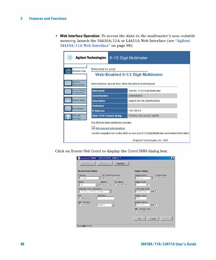
2 Features and Functions
• Web Interface Operation: To access the data in the multimeter’s non–volatile memory, launch the 34410A/11A or L4411A Web Interface (see “Agilent 34410A/11A Web Interface” on page 98):
Click on Browser Web Control to display the Control DMM dialog box:
80 34410A/11A/L4411A User’s Guide
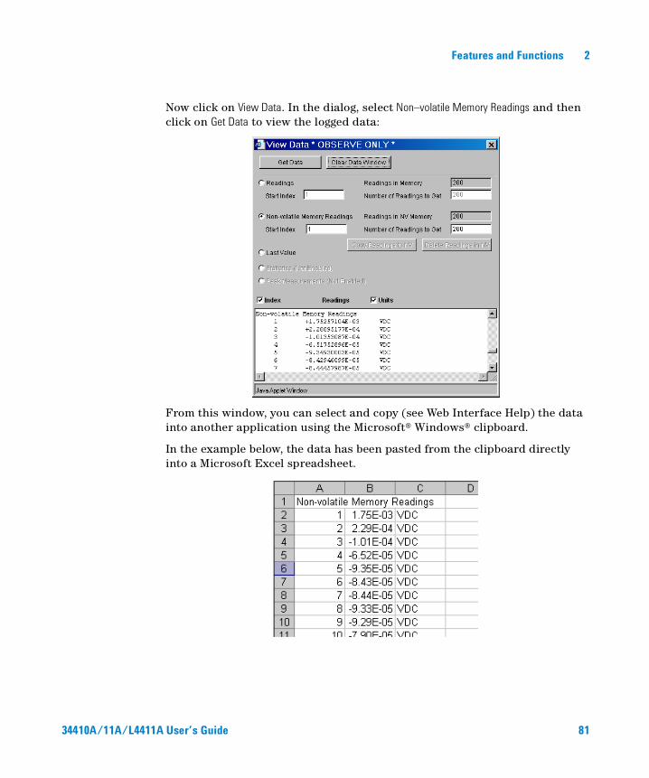
Features and Functions 2
Now click on View Data. In the dialog, select Non–volatile Memory Readings and then click on Get Data to view the logged data:
From this window, you can select and copy (see Web Interface Help) the data into another application using the Microsoft® Windows® clipboard.
In the example below, the data has been pasted from the clipboard directly into a Microsoft Excel spreadsheet.
34410A/11A/L4411A User’s Guide 81
2 Features and Functions
System-Related Operations
The utility menu accesses the following system–related operations: self–test, display of error conditions, calibration, and instrument information. These features are described in the subsections that follow.
The utility menu is also used to access the following three menus:
• REMOTE I/O menu (see Chapter 3, “Remote Interface Configuration” for a complete description of the remote interface features).
• STORE/RECALL menu (see “Multimeter State Storage” on page 48 for a complete description of the state storage feature).
• MISC SETTINGS menu (see “Miscellaneous Configuration Settings” on page 60 for a complete description of these features).
Self–Test
A power–on self–test occurs automatically when you turn on the instrument. This limited test assures you that the multimeter is operational. This self–test does not perform the extensive self test described below.
A complete self–test performs a series of internal tests, and takes about five seconds to execute.
If the power–on or complete self–test fails, an error is stored in the error queue. See the Agilent 34410A/11A/L4411A Service Guide for more information on obtaining service.
• Following the complete self–test, the instrument issues a Factory Reset (*RST) command.
• Front Panel Operation: Press
UTILITY MENU > SELF-TEST
If the test fails, the Error annunciator will light.
• Remote Interface Operation: The following command returns “+0“ if the self–test is successful or “+1“ if it fails.*TST?
Refer to the Agilent 34410A/11A/L4411A Programmer’s Reference Help for a complete description and syntax for this command.
82 34410A/11A/L4411A User’s Guide
Features and Functions 2
Error Conditions
When the front panel ERROR annunciator turns on (34410A/11A), one or more command syntax or hardware errors have been detected. A record of up to 20 errors can be stored in the instrument’s error queue.
• The instrument (34410A/11A) beeps once each time a command syntax or hardware error is generated.
• Each remote interface I/O session (for example, GPIB, USB, LAN) has its own interface–specific error queue.
• A special global error queue holds all power–on and hardware– related errors (for example, over–temperature).
• Errors are retrieved in first–in–first–out (FIFO) order. The first error returned is the first error that was stored. Errors are cleared as you read them. Once you have read all of the interface–specific errors, the errors in the global queue are retrieved.
• Errors are cleared as you read them. When you have read all errors from the interface–specific and global error queues, the ERROR annunciator turns off and the errors are cleared.
• If more than 20 errors have occurred, the last error stored in the queue (the most recent error) is replaced with –350,”Error queue overflow”. No additional errors are stored until you remove errors from the queue. If no errors have occurred when you read the error queue, the instrument responds with +0,“No error”.
• The front panel reports errors from all I/O sessions as well as the global error queue.
• Both the interface–specific and global error queues are cleared by the *CLS (Clear Status) command and when power is cycled. The errors are also cleared when you read the error queue. The error queue is not cleared by a Factory Reset (*RST) command or an Instrument Preset (SYSTem:PRESet) command.
34410A/11A/L4411A User’s Guide 83
2 Features and Functions
Reading the Error Queue
You can read the error queue either from the front panel, or from the remote interface.
• Front Panel Operation: Press
UTILITY MENU > SCPI ERRORS
Scroll through the errors using the navigation keypad. Press to clear all errors from the queue.
• Remote Interface Operation: The following command reads and clears one error from the error queue in first–in–first–out order.SYSTem:ERRor[:NEXT]?
Refer to the Agilent 34410A/11A/L4411A Programmer’s Reference Help for a complete description and syntax for this command.
Calibration
Only service–qualified personnel should calibrate the multimeter. Improper use of the front–panel CALIBRATION procedure in the UTILITY menu could result in damage to the multimeter. The multimeter is secured with a calibration security code at the factory.
Refer to the Agilent 34410A/11A/L4411A Service Guide for calibration procedures.
84 34410A/11A/L4411A User’s Guide

Features and Functions 2
Power-On and Reset State
The tables that follow show the factory defaults for various instrument settings. The parameters marked with a bullet () are stored in non–volatile memory, and are not affected by power–on or a system reset. For those parameters, the initial factory settings are shown. All other parameters are stored in volatile memory, and are reset to the indicated values at power–on, after a front–panel Reset command, or after a *RST or SYSTem:PRESet remote interface command.
Measurement Configuration Factory SettingFunction DC VoltsRange Autorange (for all functions)Resolution 6.5 digits (0.3 ppm x Range) *Integration Time NPLC On, 1 PLC *Auto zero On *Aperture Off, 1 second * Input Impedance 10 MΩ (fixed for all dc V ranges) AC Input Filter (bandwidth) 20 Hz (medium filter)Nulls (for individual measurement functions) Off, 0 (for all functions)Second Display Off*for all dc measurements
Math Operations Factory SettingMath State OffMath Registers Cleared (all registers)dB Relative Value 0dBm Reference Resistance 600 Ω
Triggering Operations Factory SettingTrigger Count 1Trigger Source ImmediateTrigger Delay Auto DelaySample Count 1Sample Source AutoSample Timer 1 second
34410A/11A/L4411A User’s Guide 85
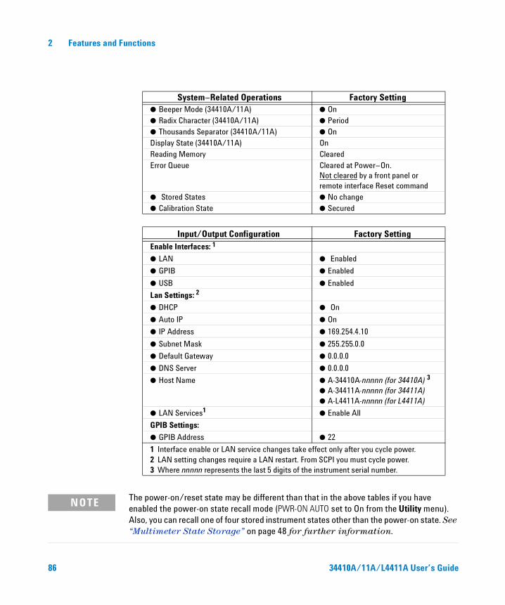
2 Features and Functions
System–Related Operations Factory Setting Beeper Mode (34410A/11A) On Radix Character (34410A/11A) Period Thousands Separator (34410A/11A) OnDisplay State (34410A/11A) OnReading Memory ClearedError Queue Cleared at Power–On.
Not cleared by a front panel or remote interface Reset command
Stored States No change Calibration State Secured
Input/Output Configuration Factory SettingEnable Interfaces: 1
LAN Enabled
GPIB Enabled
USB Enabled
Lan Settings: 2
DHCP On
Auto IP On
IP Address 169.254.4.10
Subnet Mask 255.255.0.0
Default Gateway 0.0.0.0
DNS Server 0.0.0.0
Host Name A-34410A-nnnnn (for 34410A) 3 A-34411A-nnnnn (for 34411A) A-L4411A-nnnnn (for L4411A)
LAN Services1 Enable All
GPIB Settings:
GPIB Address 22
1 Interface enable or LAN service changes take effect only after you cycle power. 2 LAN setting changes require a LAN restart. From SCPI you must cycle power. 3 Where nnnnn represents the last 5 digits of the instrument serial number.
NOTE The power-on/reset state may be different than that in the above tables if you have enabled the power-on state recall mode (PWR-ON AUTO set to On from the Utility menu). Also, you can recall one of four stored instrument states other than the power-on state. See “Multimeter State Storage” on page 48 for further information.
86 34410A/11A/L4411A User’s Guide
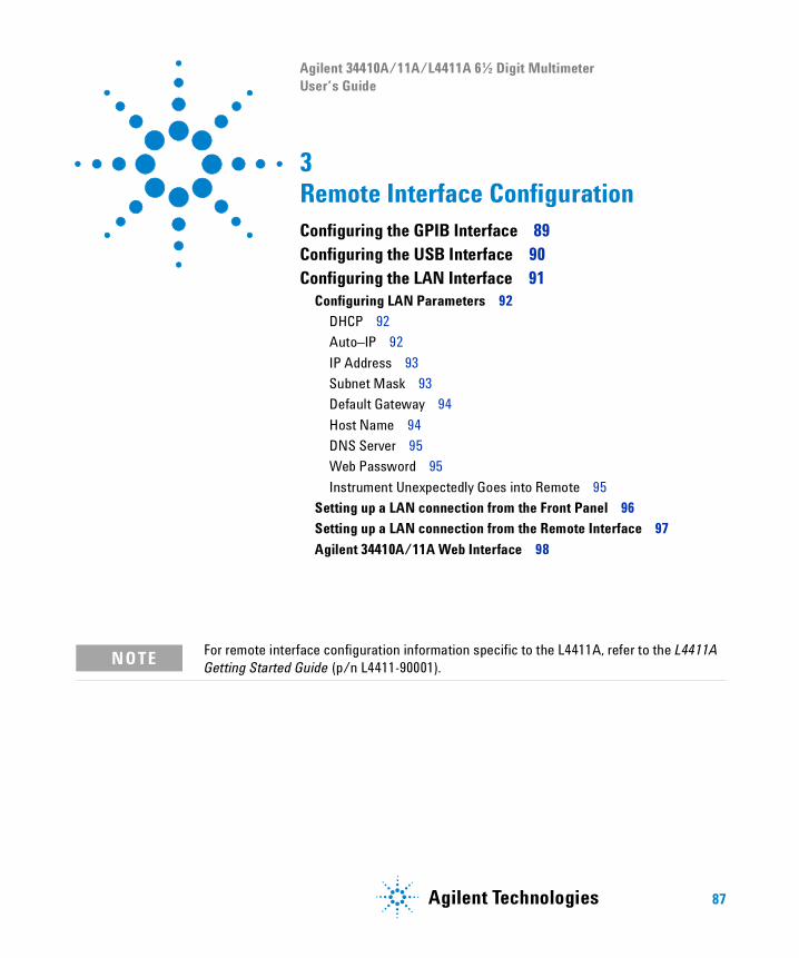
Agilent 34410A/11A/L4411A 6½ Digit Multimeter User’s Guide
3 Remote Interface ConfigurationConfiguring the GPIB Interface 89Configuring the USB Interface 90Configuring the LAN Interface 91
Configuring LAN Parameters 92
DHCP 92
Auto–IP 92
IP Address 93
Subnet Mask 93
Default Gateway 94
Host Name 94
DNS Server 95
Web Password 95
Instrument Unexpectedly Goes into Remote 95
Setting up a LAN connection from the Front Panel 96
Setting up a LAN connection from the Remote Interface 97
Agilent 34410A/11A Web Interface 98
NOTE For remote interface configuration information specific to the L4411A, refer to the L4411A Getting Started Guide (p/n L4411-90001).
87Agilent Technologies
3 Remote Interface Configuration
This chapter tells how to configure the Agilent 34410A/11A for remote interface communication. For additional information, refer to the:
• Agilent USB/LAN/GPIB Connectivity Guide for interface configuration and troubleshooting information. This manual is found on the Agilent Automation–Ready CD–ROM or at www.agilent.com/find/connectivity.
• Agilent 34410A/11A/L4411A Programmer’s Reference Help for information on programming the instrument using SCPI commands. This help file is found on the Agilent 34410A/11A/L4411A Product Reference CD–ROM.
The Agilent 34410A/11A supports GPIB, USB, and LAN interfaces. All three interfaces are enabled at power on. The front panel Remote annunciator turns on whenever there is activity on the remote interface.
• GPIB Interface You need only set the GPIB address for the instrument (the factory default is 22) and connect it to your PC using a GPIB cable (sold separately).
• USB Interface There is nothing to configure on your instrument for a USB connection. Just connect the instrument to your PC using the USB 2.0 cable included with the instrument.
• LAN Interface By default, DHCP is enabled on the instrument, which may enable network communication over the LAN interface (10BaseT/100BaseTx). You may need to set several configuration parameters as described in the LAN configuration sections that follow.
NOTE To configure and verify an interface connection between the 34410A/11A and your PC, use the Agilent IO Libraries Suite (E2094M Agilent IO Libraries for Windows) or an equivalent. For more information about Agilent's I/O connectivity software, go to www.agilent.com/find/iolib.
• Agilent IO Libraries Suite for Windows® 98/2000/ME/XP. For more information and to install this software see the Agilent Automation–Ready CD-ROM provided with your 34410A/11A.
• To download the latest (or previous) version of this software for Windows® 98/NT/2000/ME/XP from the Web, go to www.agilent.com/find/iolib.
88 34410A/11A/L4411A User’s Guide
Remote Interface Configuration 3
Configuring the GPIB Interface
Each device on the GPIB (IEEE–488) interface must have a unique address. You can set the multimeter’s address to any integral value between 0 and 30. The address is set to “22” when the instrument is shipped from the factory.
• Your computer’s GPIB interface card has its own address. Be sure to avoid using that address for any instrument on the interface bus.
• The GPIB address is stored in non–volatile memory, and does not change when power has been off, after a Factory Reset (*RST) command, or after an Instrument Preset (SYSTem:PRESet) command.
• Front Panel Operation: Press
UTILITY MENU > REMOTE I/O > GPIB > ENABLE GPIB? > GPIB ADDRESS
After enabling or disabling GPIB, you must cycle the power for the change to take effect.
• Remote Interface Operation: The following command enables the GPIB remote interface:SYSTem:COMMunicate:ENABle ON,GPIB
The following command queries the state of the GPIB interface:SYSTem:COMMunicate:ENABle? GPIBThis query returns a “0” (OFF) or a “1” (ON).
The following command sets the multimeter’s GPIB (IEEE–488) address:SYSTem:COMMunicate:GPIB:ADDRess <address>
The following query returns the IP address, (for example “+22”):SYSTem:COMMunicate:GPIB:ADDRess?
Refer to the Agilent 34410A/11A/L4411A Programmer’s Reference Help for complete description and syntax for these commands.
34410A/11A/L4411A User’s Guide 89

3 Remote Interface Configuration
Configuring the USB Interface
For the USB interface, no configuration parameters are required to set up the multimeter. Connect your multimeter to a USB port on your computer. Note that it may take several seconds for the computer to recognize and establish a connection to the multimeter.
• Front Panel Operation: Press
UTILITY MENU > REMOTE I/O > USB > ENABLE USB? > USB ID
After enabling or disabling USB, you must cycle the power for the change to take effect.
Note that you generally do not need to know what the USB ID string is for your instrument, as connections are automatic for most software. However, the string is unique to your instrument and has the following format:USB0::<mfgID>::<modID::<serial#>::INSTR
You will need to scroll the USB ID ( ) to view the entire string.
• Remote Interface Operation: The following command enables the USB remote interface:SYSTem:COMMunicate:ENABle ON,USB
The following command queries the state of the USB interface:SYSTem:COMMunicate:ENABle? USB
This query returns a “0” (OFF) or a “1” (ON).
Refer to the Agilent 34410A/11A/L4411A Programmer’s Reference Help for complete description and syntax for these commands.
90 34410A/11A/L4411A User’s Guide
Remote Interface Configuration 3
Configuring the LAN Interface
By default, LAN connectivity with DHCP (Dynamic Host Configuration Protocol) is enabled on the 34410A/11A. In many cases you can simply let DHCP assign the necessary parameters for a LAN connection. However, you can also turn off DHCP and set parameters manually.
LAN Parameters You may choose to manually set the following parameters, as described in the subsections that follow. Following these descriptions are procedures for setting up a LAN configuration from the front panel and the remote interface.
• IP Address
• Subnet Mask
• Default Gateway
• DNS Server
• Host Name
• LAN Services (Visa LAN, Sockets, Telnet, Agilent Web Server)
• Web Password
NOTE The IP Address, Subnet Mask, Default Gateway, and DNS Server parameters use “dot-notation” addresses. Dot–notation addresses (“nnn.nnn.nnn.nnn” where “nnn” is a byte value) must be expressed with care:
Most computers will interpret byte values with leading zeros as octal numbers. For example, “255.255.020.011” is actually equivalent to decimal “255.255.16.9” not “255.255.20.11” because the computer will interpret “.020” as “16” expressed in octal, and “.011” as “9”.
However, the multimeter assumes that all dot–notation addresses are expressed as decimal byte values and strips all leading zeros from these byte values. Thus, attempting to set an IP address of “255.255.020.011” will become “255.255.20.11” (a purely decimal expression). Be sure to enter the exact expression, “255.255.20.11”, in your computer web software to address the instrument. To avoid confusion, use only decimal expressions of byte values (0 to 255), with no leading zeros.
34410A/11A/L4411A User’s Guide 91

3 Remote Interface Configuration
Configuring LAN Parameters
DHCP
DHCP is a protocol for automatically assigning a dynamic IP address, subnet mask and default gateway to a device on a network, and is typically the easiest way to configure your multimeter for remote communication using the LAN interface.
• Changing the DHCP setting will cause an automatic LAN restart.
• When DHCP is enabled (factory setting), the multmeter will try to obtain an IP address from a DHCP server. If a DHCP server is found, it will assign a dynamic IP address, Subnet Mask, and Default Gateway to the instrument. The DHCP server may also assign the DNS address, and may change the specified Host Name if a manually specified Host Name is already in use.
• When DHCP is disabled or unavailable, the multimeter will use the static IP address, Subnet Mask, and Default Gateway during power–on.
• If a DHCP LAN address is not assigned by a DHCP server, then a static IP will be assumed after approximately 1 minute.
• If Auto–IP is enabled, a dynamic (rather than static) IP address will be assigned by the server at power–on.
Auto–IP
The Auto–IP standard automatically assigns an IP address to the multimeter when on a network that does not have DHCP servers.
• Changing the Auto–IP setting will cause an automatic LAN reset.
• Auto–IP allocates IP addresses from the link– local address range (169.254.xxx.xxx).
• From the factory, the Auto–IP setting is enabled.• The IP address is stored in non–volatile memory, and does not change when
power has been off, after a Factory Reset (*RST) command, or after an Instrument Preset (SYSTem:PRESet) command.
92 34410A/11A/L4411A User’s Guide
Remote Interface Configuration 3
IP Address
An Internet Protocol (IP) Address is required for all IP and TCP/IP communications with the instrument. If DHCP is enabled (factory setting), the specified static IP address is not used. However, if the DHCP server fails to assign a valid IP address, or if DHCP and Auto–IP are both off, the currently configured static IP address will be used.
• Changing the IP address will cause an automatic LAN reset.
• The factory–set default IP Address is “169.254.4.10”.
• If you are planning to use a static IP address on a corporate LAN, contact your network administrator to obtain a fixed IP address to be used exclusively for your instrument.
• The IP address is stored in non–volatile memory, and does not change when power has been off, after a Factory Reset (*RST) command, or after an Instrument Preset (SYSTem:PRESet) command.
Subnet Mask
The multimeter uses the Subnet Mask to determine if a client IP address is on the same local subnet. When a client IP address is on a different subnet, all packets must be sent to the Default Gateway. Contact your network administrator to determine if subnetting is being used and for the correct Subnet Mask.
• Changing the Subnet Mask setting will cause an automatic LAN reset.
• The default Subnet Mask for the 34410A/11A multimeter is “255.255.0.0”.
• A value of “0.0.0.0” or “255.255.255.255” indicates that subnetting is not being used.
• The Subnet Mask is stored in non–volatile memory, and does not change when power has been off, after a Factory Reset (*RST) command, or after an Instrument Preset (SYSTem:PRESet) command.
34410A/11A/L4411A User’s Guide 93
3 Remote Interface Configuration
Default Gateway
A Default Gateway address allows the multimeter to communicate with systems that are not on the local subnet. Thus, this is the Default Gateway where packets are sent which are destined for a device not on the local subnet, as determined by the Subnet Mask setting. Contact your network administrator to determine if a gateway is being used and for the correct address.
• Changing the Default Gateway setting will cause an automatic LAN reset.
• The default for the multimeter is “0.0.0.0” (no gateway, and subnetting is not being used).
• The Default Gateway is stored in non–volatile memory, and does not change when power has been off, after a Factory Reset (*RST) command, or after an Instrument Preset (SYSTem:PRESet) command.
Host Name
The Host Name is the host portion of the domain name, which is translated into an IP address.
• Changing the Host Name will cause an automatic LAN reset.
• The default Host Name for the multimeter is “A–34410A–nnnnn” for the 34410A, and “A–34411A–nnnnn” for the 34411A, where nnnnn is the last five digits of the instrument’s serial number representation.
• If Dynamic Domain Name System (DNS) is available on your network and your multimeter uses DHCP, the Host Name is registered with the Dynamic DNS service at power–on.
• The Host Name is stored in non–volatile memory, and does not change when power has been off, after a Factory Reset (*RST) command, or after an Instrument Preset (SYSTem:PRESet) command.
94 34410A/11A/L4411A User’s Guide

Remote Interface Configuration 3
DNS Server
The Domain Name Service (DNS) is an Internet service that translates Domain names into IP addresses. Contact your network administrator to determine if DNS is being used and for the correct address.
• If you change the DNS address, you must cycle power on the multimeter to activate the new setting.
• The default DNS Address for the multimeter is “0.0.0.0”.
• The DNS Server address is stored in non–volatile memory, and does not change when power has been off, after a Factory Reset (*RST) command, or after an Instrument Preset (SYSTem:PRESet) command.
Web Password
You can control access to certain features of the 34410A/11A Web Interface (see “Agilent 34410A/11A Web Interface” on page 98) using password protection. The password is disabled by default. You can enable and set a web password from the front panel. A web password consists of up to 12 alphanumeric characters.
Instrument Unexpectedly Goes into Remote
If your 34410A/11A unexpectedly goes into remote mode, it is likely because you have the instrument configured to the LAN on someone else’s host controller. Operations on that host controller can query your instrument causing it to go into remote mode. To prevent this, do any of the following:
• Disconnect the instrument from the LAN.
• Disable the LAN interface from the front panel (Utility menu).
• Use SYST:COMM:LAN:HISTory? to determine the IP address that is causing the problem. Then delete your instrument’s LAN address from that host controller.
34410A/11A/L4411A User’s Guide 95
3 Remote Interface Configuration
Setting up a LAN connection from the Front Panel
Press
UTILITY MENU > REMOTE I/O > LAN > ENABLE LAN? > LAN SETTINGS > VIEW | MODIFY
• Select VIEW to view the current LAN settings.
• Select MODIFY to change the LAN settings. The following submenus are displayed:
1 RESET LAN? – NO or YES
2 DHCP – OFF or ON
3 AUTO IP – OFF or ON
4 IP ADDRESS. – Set IP address in dot notation using navigation keypad. This parameter appears only if both DHCP and AUTO IP are OFF.
5 SUBNET MASK – Set subnet mask in dot notation using navigation keypad. This parameter appears only if both DHCP and AUTO IP are OFF.
6 DEF GATEWAY – Set default gateway in dot notation using navigation keypad. This parameter appears only if both DHCP and AUTO IP are OFF.
7 DNS SERVER – Set DNS address in dot notation using navigation keypad. This parameter appears only if both DHCP and AUTO IP are OFF.
8 HOST NAME – Enter desired host name using navigation keypad. The Host Name must be an string of alphanumeric characters plus dashes (“–”), up to 15 characters, with the first character a letter.
9 LAN SERVICES – ENABLE ALL or SELECT. SELECT allows you to enable or disable the individual services (VISA LAN, SOCKETS, TELNET or WEB SERVER).
If you disable or re–enable any of the LAN services, you must cycle the power on the instrument for the change to take effect.
10 WEB PASSWORD – DISABLE or ENABLE. Select ENABLE and use the navigation keypad to enter the desired password, up to 12 alphanumeric characters in length.
NOTE If you disable or re–enable the LAN interface, or any of the LAN services, you must cycle the power on the instrument to activate the new configuration. Other settings are activated by a LAN restart when you exit the LAN menu.
96 34410A/11A/L4411A User’s Guide

Remote Interface Configuration 3
Setting up a LAN connection from the Remote Interface
Use the following SCPI commands to configure the LAN interface.
• To enable or disable the LAN remote interface:SYSTem:COMMunicate:ENABle OFF>0>ON>1,LAN
• To enable or disable the use of DHCP for the LAN interface:SYSTem:COMMunicate:LAN:DHCP OFF>0>ON>1
• To enable or disable the use of Auto–IP for the LAN interface:SYSTem:COMMunicate:LAN:AUTOip[STATe] OFF>0>ON>1
• To assign the LAN a static IP address:SYSTem:COMMunicate:LAN:IPADdress “<address>”
• To assign a LAN Subnet Mask:SYSTem:COMMunicate:LAN:SMASk “<mask>”
• To assign a LAN Default Gateway:SYSTem:COMMunicate:LAN:GATEway “<address>”
• To assign a LAN Host Name:SYSTem:COMMunicate:LAN:HOSTname “<name>”
• To assign the LAN a static DNS address:SYSTem:COMMunicate:LAN:DNS “<address>”
• To assign a LAN Domain Name:SYSTem:COMMunicate:LAN:DOMain “<name>”
Query forms of these commands are also available. Refer to the Agilent 34410A/11A/L4411A Programmer’s Reference Help for complete command description and syntax.
NOTE If you disable or re–enable the LAN interface, you must cycle the power for the change to take effect. You must also cylcle power when you disable or re–enable any of the LAN services, or change any LAN settings from the remote interface using SCPI commands.
34410A/11A/L4411A User’s Guide 97
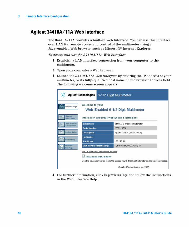
3 Remote Interface Configuration
Agilent 34410A/11A Web Interface
The 34410A/11A provides a built–in Web Interface. You can use this interface over LAN for remote access and control of the multimeter using a Java–enabled Web browser, such as Microsoft® Internet Explorer.
To access and use the 34410A/11A Web Interface:
1 Establish a LAN interface connection from your computer to the multimeter.
2 Open your computer’s Web browser.
3 Launch the 34410A/11A Web Interface by entering the IP address of your multimeter, or its fully–qualified host name, in the browser address field. The following welcome screen appears.
4 For further information, click Help with this Page and follow the instructions in the Web Interface Help.
98 34410A/11A/L4411A User’s Guide

Agilent 34401A/11A/L4411A 6½ Digit Multimeter User’s Guide
4Measurement TutorialThe Agilent 34410A/11A/L4411A multimeter is capable of making highly accurate measurements. In order to achieve the greatest accuracy, you must take the necessary steps to eliminate potential measurement errors. This chapter describes common errors found in measurements and gives suggestions to help you avoid these errors.
DC Measurement Considerations 101Thermal EMF Errors 101
Loading Errors (dc volts) 101Noise Rejection 102
Rejecting Power–Line Noise Voltages 102
Common Mode Rejection (CMR) 102
Noise Caused by Magnetic Loops 103
Noise Caused by Ground Loops 103Resistance Measurement Considerations 104
4–Wire Ohms Measurements 104
Removing Test Lead Resistance Errors 105
Minimizing Power Dissipation Effects 105
Errors in High Resistance Measurements 105
True RMS AC Measurements 106True RMS Accuracy and High–Frequency Signal Content 107
Estimating High–Frequency (Out–of–Band) Error 110
99Agilent Technologies
4 Measurement Tutorial
Other Primary Measurement Functions 112Frequency and Period Measurement Errors 112
DC Current Measurements 112
Capacitance Measurements 113
Temperature Measurements 115
Probe Type Choice 115
2–Wire vs. 4–Wire Measurements 115
Auto Zero On/Off 116
Integration 116
Offset Compensation 116
NULL Reading: 116
High-Speed Measurements 117Making High–Speed AC Measurements 117
Making High–Speed dc and Resistance Measurements 118
Other Sources of Measurement Error 119Settling Time Effects 119
Loading Errors (ac volts) 119
Measurements Below Full Scale 120
High–Voltage Self–Heating Errors 120
AC Current Measurement Errors (Burden Voltage) 120
Low–Level Measurement Errors 120
Common Mode Errors 122
Leakage Current Errors 122
100 34410A/11A/L4411A User’s Guide
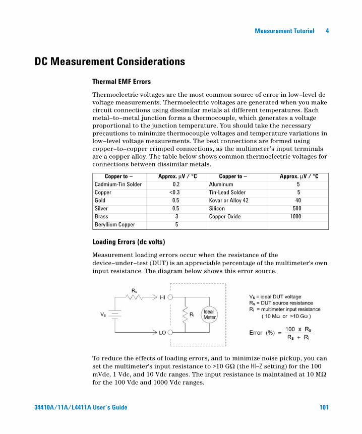
Measurement Tutorial 4
DC Measurement Considerations
Thermal EMF Errors
Thermoelectric voltages are the most common source of error in low–level dc voltage measurements. Thermoelectric voltages are generated when you make circuit connections using dissimilar metals at different temperatures. Each metal–to–metal junction forms a thermocouple, which generates a voltage proportional to the junction temperature. You should take the necessary precautions to minimize thermocouple voltages and temperature variations in low–level voltage measurements. The best connections are formed using copper–to–copper crimped connections, as the multimeter’s input terminals are a copper alloy. The table below shows common thermoelectric voltages for connections between dissimilar metals.
Loading Errors (dc volts)
Measurement loading errors occur when the resistance of the device–under–test (DUT) is an appreciable percentage of the multimeter's own input resistance. The diagram below shows this error source.
To reduce the effects of loading errors, and to minimize noise pickup, you can set the multimeter's input resistance to >10 GΩ (the HI–Z setting) for the 100 mVdc, 1 Vdc, and 10 Vdc ranges. The input resistance is maintained at 10 MΩ for the 100 Vdc and 1000 Vdc ranges.
Copper to – Approx. µV / °C Copper to – Approx. µV / °CCadmium-Tin Solder 0.2 Aluminum 5Copper <0.3 Tin-Lead Solder 5Gold 0.5 Kovar or Alloy 42 40Silver 0.5 Silicon 500Brass 3 Copper-Oxide 1000Beryllium Copper 5
34410A/11A/L4411A User’s Guide 101
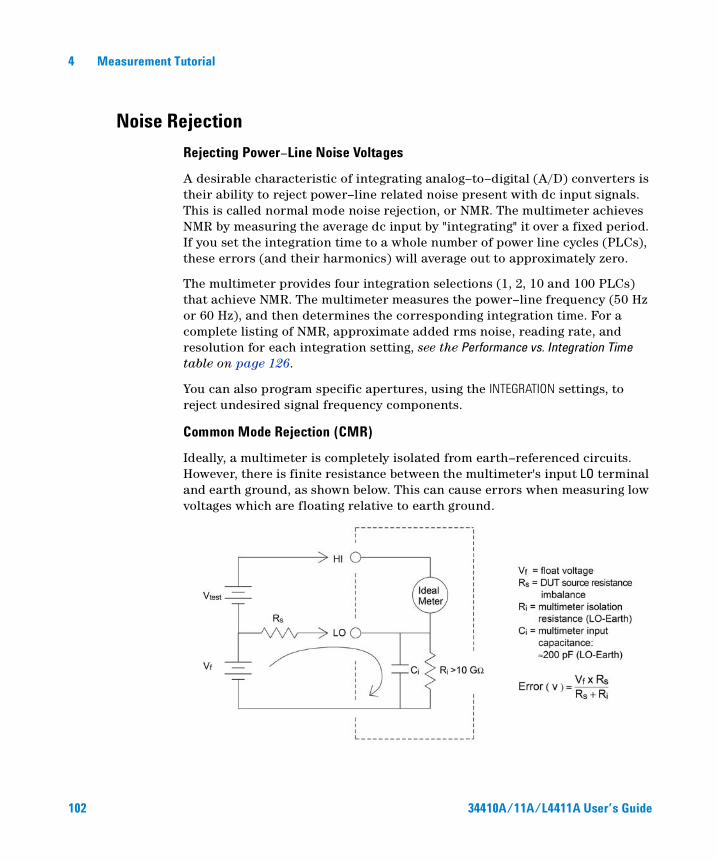
4 Measurement Tutorial
Noise Rejection
Rejecting Power–Line Noise Voltages
A desirable characteristic of integrating analog–to–digital (A/D) converters is their ability to reject power–line related noise present with dc input signals. This is called normal mode noise rejection, or NMR. The multimeter achieves NMR by measuring the average dc input by "integrating" it over a fixed period. If you set the integration time to a whole number of power line cycles (PLCs), these errors (and their harmonics) will average out to approximately zero.
The multimeter provides four integration selections (1, 2, 10 and 100 PLCs) that achieve NMR. The multimeter measures the power–line frequency (50 Hz or 60 Hz), and then determines the corresponding integration time. For a complete listing of NMR, approximate added rms noise, reading rate, and resolution for each integration setting, see the Performance vs. Integration Time table on page 126.
You can also program specific apertures, using the INTEGRATION settings, to reject undesired signal frequency components.
Common Mode Rejection (CMR)
Ideally, a multimeter is completely isolated from earth–referenced circuits. However, there is finite resistance between the multimeter's input LO terminal and earth ground, as shown below. This can cause errors when measuring low voltages which are floating relative to earth ground.
102 34410A/11A/L4411A User’s Guide
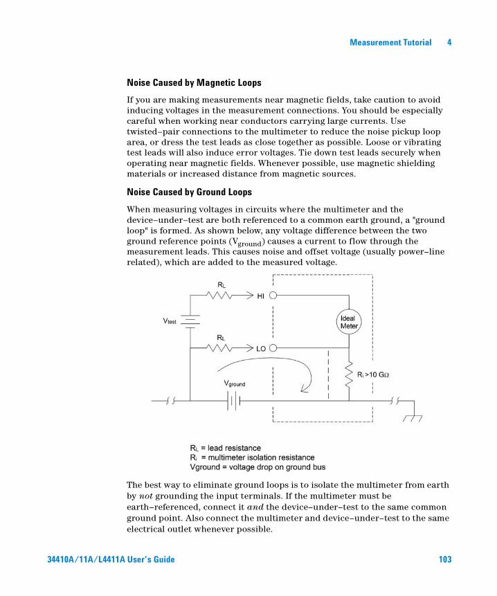
Measurement Tutorial 4
Noise Caused by Magnetic Loops
If you are making measurements near magnetic fields, take caution to avoid inducing voltages in the measurement connections. You should be especially careful when working near conductors carrying large currents. Use twisted–pair connections to the multimeter to reduce the noise pickup loop area, or dress the test leads as close together as possible. Loose or vibrating test leads will also induce error voltages. Tie down test leads securely when operating near magnetic fields. Whenever possible, use magnetic shielding materials or increased distance from magnetic sources.
Noise Caused by Ground Loops
When measuring voltages in circuits where the multimeter and the device–under–test are both referenced to a common earth ground, a "ground loop" is formed. As shown below, any voltage difference between the two ground reference points (Vground) causes a current to flow through the measurement leads. This causes noise and offset voltage (usually power–line related), which are added to the measured voltage.
The best way to eliminate ground loops is to isolate the multimeter from earth by not grounding the input terminals. If the multimeter must be earth–referenced, connect it and the device–under–test to the same common ground point. Also connect the multimeter and device–under–test to the same electrical outlet whenever possible.
34410A/11A/L4411A User’s Guide 103
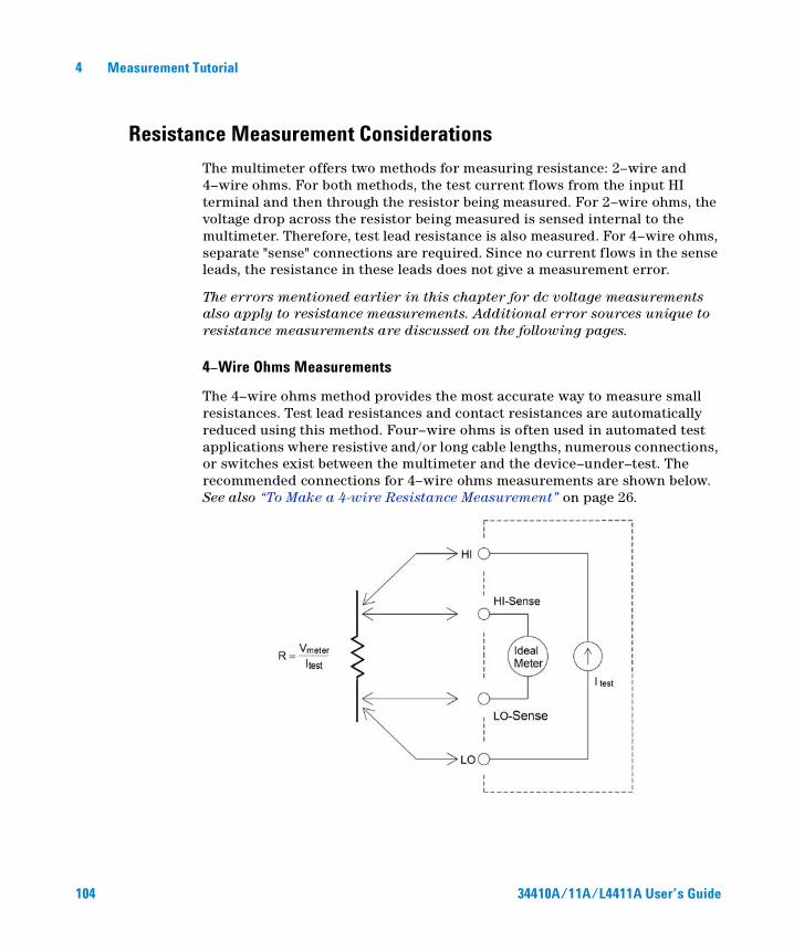
4 Measurement Tutorial
Resistance Measurement Considerations
The multimeter offers two methods for measuring resistance: 2–wire and 4–wire ohms. For both methods, the test current flows from the input HI terminal and then through the resistor being measured. For 2–wire ohms, the voltage drop across the resistor being measured is sensed internal to the multimeter. Therefore, test lead resistance is also measured. For 4–wire ohms, separate "sense" connections are required. Since no current flows in the sense leads, the resistance in these leads does not give a measurement error.
The errors mentioned earlier in this chapter for dc voltage measurements also apply to resistance measurements. Additional error sources unique to resistance measurements are discussed on the following pages.
4–Wire Ohms Measurements
The 4–wire ohms method provides the most accurate way to measure small resistances. Test lead resistances and contact resistances are automatically reduced using this method. Four–wire ohms is often used in automated test applications where resistive and/or long cable lengths, numerous connections, or switches exist between the multimeter and the device–under–test. The recommended connections for 4–wire ohms measurements are shown below. See also “To Make a 4-wire Resistance Measurement” on page 26.
104 34410A/11A/L4411A User’s Guide
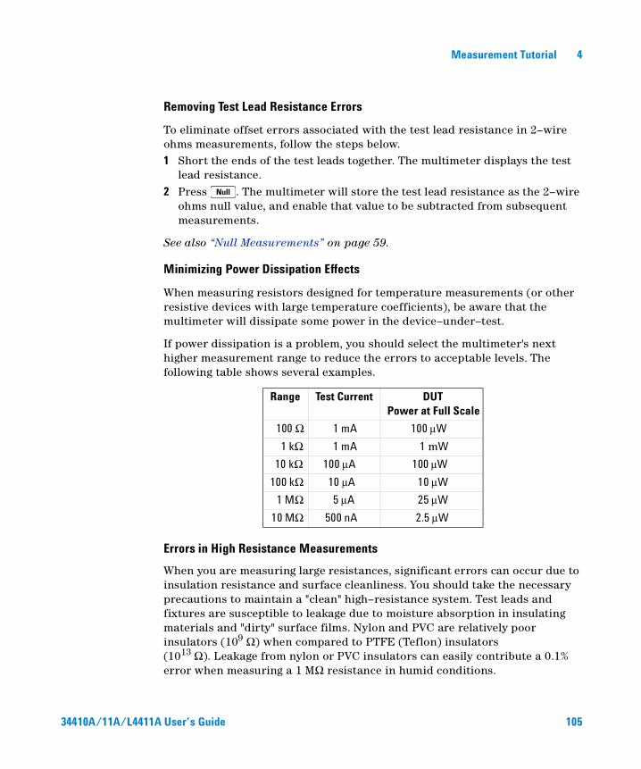
Measurement Tutorial 4
Removing Test Lead Resistance Errors
To eliminate offset errors associated with the test lead resistance in 2–wire ohms measurements, follow the steps below.1 Short the ends of the test leads together. The multimeter displays the test
lead resistance.2 Press . The multimeter will store the test lead resistance as the 2–wire
ohms null value, and enable that value to be subtracted from subsequent measurements.
See also “Null Measurements” on page 59.
Minimizing Power Dissipation Effects
When measuring resistors designed for temperature measurements (or other resistive devices with large temperature coefficients), be aware that the multimeter will dissipate some power in the device–under–test.
If power dissipation is a problem, you should select the multimeter's next higher measurement range to reduce the errors to acceptable levels. The following table shows several examples.
Errors in High Resistance Measurements
When you are measuring large resistances, significant errors can occur due to insulation resistance and surface cleanliness. You should take the necessary precautions to maintain a "clean" high–resistance system. Test leads and fixtures are susceptible to leakage due to moisture absorption in insulating materials and "dirty" surface films. Nylon and PVC are relatively poor insulators (109 Ω) when compared to PTFE (Teflon) insulators (1013 Ω). Leakage from nylon or PVC insulators can easily contribute a 0.1% error when measuring a 1 MΩ resistance in humid conditions.
Range Test Current DUT Power at Full Scale
100 Ω 1 mA 100 µW
1 kΩ 1 mA 1 mW
10 kΩ 100 µA 100 µW
100 kΩ 10 µA 10 µW
1 MΩ 5 µA 25 µW
10 MΩ 500 nA 2.5 µW
34410A/11A/L4411A User’s Guide 105
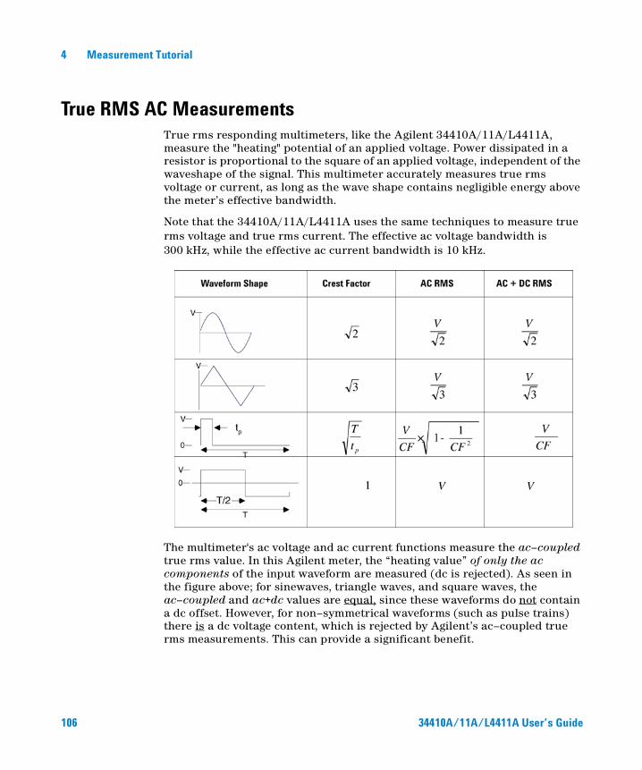
4 Measurement Tutorial
True RMS AC MeasurementsTrue rms responding multimeters, like the Agilent 34410A/11A/L4411A, measure the "heating" potential of an applied voltage. Power dissipated in a resistor is proportional to the square of an applied voltage, independent of the waveshape of the signal. This multimeter accurately measures true rms voltage or current, as long as the wave shape contains negligible energy above the meter’s effective bandwidth.
Note that the 34410A/11A/L4411A uses the same techniques to measure true rms voltage and true rms current. The effective ac voltage bandwidth is 300 kHz, while the effective ac current bandwidth is 10 kHz.
The multimeter's ac voltage and ac current functions measure the ac–coupled true rms value. In this Agilent meter, the “heating value” of only the ac components of the input waveform are measured (dc is rejected). As seen in the figure above; for sinewaves, triangle waves, and square waves, the ac–coupled and ac+dc values are equal, since these waveforms do not contain a dc offset. However, for non–symmetrical waveforms (such as pulse trains) there is a dc voltage content, which is rejected by Agilent’s ac–coupled true rms measurements. This can provide a significant benefit.
106 34410A/11A/L4411A User’s Guide
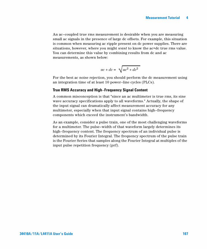
Measurement Tutorial 4
An ac–coupled true rms measurement is desirable when you are measuring small ac signals in the presence of large dc offsets. For example, this situation is common when measuring ac ripple present on dc power supplies. There are situations, however, where you might want to know the ac+dc true rms value. You can determine this value by combining results from dc and ac measurements, as shown below:
For the best ac noise rejection, you should perform the dc measurement using an integration time of at least 10 power–line cycles (PLCs).
True RMS Accuracy and High–Frequency Signal Content
A common misconception is that "since an ac multimeter is true rms, its sine wave accuracy specifications apply to all waveforms." Actually, the shape of the input signal can dramatically affect measurement accuracy for any multimeter, especially when that input signal contains high–frequency components which exceed the instrument’s bandwidth.
As an example, consider a pulse train, one of the most challenging waveforms for a multimeter. The pulse–width of that waveform largely determines its high–frequency content. The frequency spectrum of an individual pulse is determined by its Fourier Integral. The frequency spectrum of the pulse train is the Fourier Series that samples along the Fourier Integral at multiples of the input pulse repetition frequency (prf).
34410A/11A/L4411A User’s Guide 107
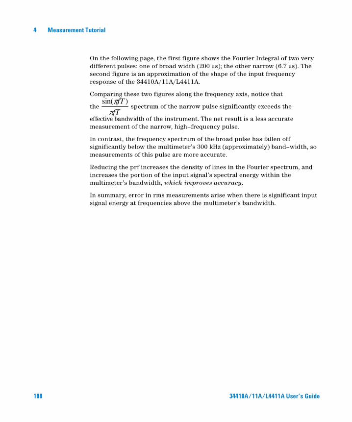
4 Measurement Tutorial
On the following page, the first figure shows the Fourier Integral of two very different pulses: one of broad width (200 µs); the other narrow (6.7 µs). The second figure is an approximation of the shape of the input frequency response of the 34410A/11A/L4411A.
Comparing these two figures along the frequency axis, notice that
the spectrum of the narrow pulse significantly exceeds the
effective bandwidth of the instrument. The net result is a less accurate measurement of the narrow, high–frequency pulse.
In contrast, the frequency spectrum of the broad pulse has fallen off significantly below the multimeter’s 300 kHz (approximately) band–width, so measurements of this pulse are more accurate.
Reducing the prf increases the density of lines in the Fourier spectrum, and increases the portion of the input signal’s spectral energy within the multimeter’s bandwidth, which improves accuracy.
In summary, error in rms measurements arise when there is significant input signal energy at frequencies above the multimeter’s bandwidth.
fT
fT
ππ )sin(
108 34410A/11A/L4411A User’s Guide
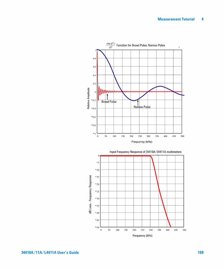
Measurement Tutorial 4
34410A/11A/L4411A User’s Guide 109

4 Measurement Tutorial
Estimating High–Frequency (Out–of–Band) Error
A common way to describe signal waveshapes is to refer to their “Crest Factor”. Crest factor is the ratio of the peak value to rms value of a waveform. For a pulse train, for example, the crest factor is approximately equal to the square root of the inverse of the duty cycle.
Notice that crest factor is a composite parameter, dependent upon the pulse–width and repetition frequency; crest factor alone is not enough to characterize the frequency content of a signal.
Traditionally, DMMs include a crest factor derating table that applies at all frequencies. The measurement algorithm used in the 34410A/11A/L4411A multimeters is not inherently sensitive to crest factor, so no such derating is necessary. With this multimeter, as discussed in the previous section, the focal issue is high–frequency signal content which exceeds the multimeter’s bandwidth.
For periodic signals, the combination of crest factor and repetition rate can suggest the amount of high–frequency content and associated measurement error. The first zero crossing of a simple pulse occurs at:
This gives an immediate impression of the high-frequency,content by identifying where this crossing occurs as a function of crest factor:
ptf
11 =
prfCFf ⋅= 21
110 34410A/11A/L4411A User’s Guide

Measurement Tutorial 4
The following table shows the typical error for various pulse waveforms as a function of input pulse frequency:
This table gives an additional error for each waveform, to be added to the value from the accuracy table provided in Chapter 5, “Specfications.”
The 34410A/11A/L4411A specifications are valid for CF ≤ 10, provided there is insignificant signal energy above the 300 kHz bandwidth for voltage, or the 10 kHz bandwidth for current. Multimeter performance is not specified for CF > 10, or when significant out-of-band signal content is present.
Example:
A pulse train with level 1 Vrms, is measured on the 1 V range. It has pulse heights of 3 V (that is, a Crest Factor of 3) and duration 111 ms. The prf can be calculated to be 1000 Hz, as follows:
Thus, from the table above, this ac waveform can be measured with 0.18 percent additional error.
Typical error for square wave, triangular wave, and pulse trains of CF=3, 5, or 10
prf square wave triangle wave CF=3 CF=5 CF=10
200 –0.02% 0.00% –0.04% –0.09% –0.34%
1000 –0.07% 0.00% –0.18% –0.44% –1.71%
2000 –0.14% 0.00% –0.34% –0.88% –3.52%
5000 –0.34% 0.00% –0.84% –2.29% –8.34%
10000 –0.68% 0.00% –1.75% –4.94% –26.00%
20000 –1.28% 0.00% –3.07% –8.20% –45.70%
50000 –3.41% –0.04% –6.75% –32.0% –65.30%
100000 –5.10% –0.12% –21.8% –50.6% –75.40%
34410A/11A/L4411A User’s Guide 111
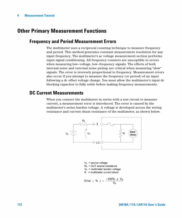
4 Measurement Tutorial
Other Primary Measurement Functions
Frequency and Period Measurement ErrorsThe multimeter uses a reciprocal counting technique to measure frequency and period. This method generates constant measurement resolution for any input frequency. The multimeter's ac voltage measurement section performs input signal conditioning. All frequency counters are susceptible to errors when measuring low–voltage, low–frequency signals. The effects of both internal noise and external noise pickup are critical when measuring "slow" signals. The error is inversely proportional to frequency. Measurement errors also occur if you attempt to measure the frequency (or period) of an input following a dc offset voltage change. You must allow the multimeter's input dc blocking capacitor to fully settle before making frequency measurements.
DC Current MeasurementsWhen you connect the multimeter in series with a test circuit to measure current, a measurement error is introduced. The error is caused by the multimeter's series burden voltage. A voltage is developed across the wiring resistance and current shunt resistance of the multimeter, as shown below.
112 34410A/11A/L4411A User’s Guide
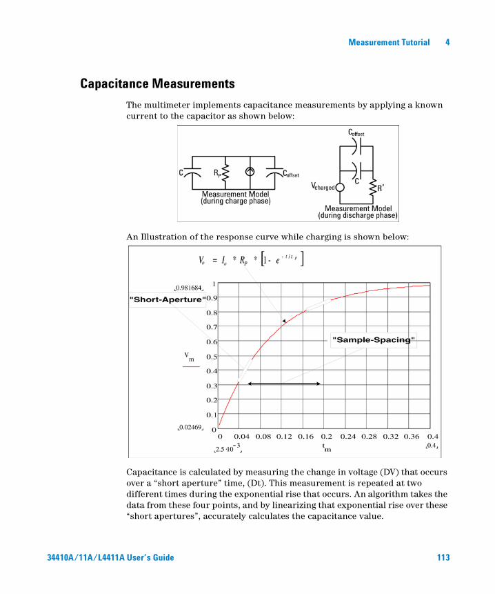
Measurement Tutorial 4
Capacitance Measurements
The multimeter implements capacitance measurements by applying a known current to the capacitor as shown below:
An Illustration of the response curve while charging is shown below:
Capacitance is calculated by measuring the change in voltage (DV) that occurs over a “short aperture” time, (Dt). This measurement is repeated at two different times during the exponential rise that occurs. An algorithm takes the data from these four points, and by linearizing that exponential rise over these “short apertures”, accurately calculates the capacitance value.
34410A/11A/L4411A User’s Guide 113
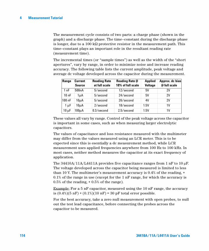
4 Measurement Tutorial
The measurement cycle consists of two parts: a charge phase (shown in the graph) and a discharge phase. The time–constant during the discharge phase is longer, due to a 100 kΩ protective resistor in the measurement path. This time–constant plays an important role in the resultant reading rate (measurement time).
The incremental times (or “sample times”) as well as the width of the “short apertures”, vary by range, in order to minimize noise and increase reading accuracy. The following table lists the current amplitude, peak voltage and average dc voltage developed across the capacitor during the measurement.
These values all vary by range. Control of the peak voltage across the capacitor is important in some cases, such as when measuring larger electrolytic capacitors.
The values of capacitance and loss resistance measured with the multimeter may differ from the values measured using an LCR meter. This is to be expected since this is esentially a dc measurement method, while LCR measurement uses applied frequencies anywhere from 100 Hz to 100 kHz. In most cases, neither method measures the capacitor at its exact frequency of application.
The 34410A/11A/L4411A provides five capacitance ranges from 1 nF to 10 µF. The voltage developed across the capacitor being measured is limited to less than 10 V. The multimeter’s measurement accuracy is 0.4% of the reading, + 0.1% of the range in use (except for the 1 nF range, for which the accuracy is 0.5% of the reading, + 0.5% of the range).
Example: For a 5 nF capacitor, measured using the 10 nF range, the accuracy is (0.4%)(5 nF) + (0.1%)(10 nF) = 30 pF total error possible.
For the best accuracy, take a zero null measurement with open probes, to null out the test lead capacitance, before connecting the probes across the capacitor to be measured.
Range CurrentSource
Reading Rateat full scale
Reading Rate @10% of full scale
AppliedVoltage
Approx. dc bias@ full scale
1 nF 500nA 5/second 12/second 5V 2V
10 nF 1µA 5/second 24/second 5V 2V
100 nF 10µA 5/second 26/second 4V 2V
1 µF 10µA 2/second 18/second 1.5V 1V
10 µF 100µA 0.3/second 2.5/second 1.5V 1V
114 34410A/11A/L4411A User’s Guide
Measurement Tutorial 4
Temperature MeasurementsThe multimeter allows the measurement of temperature by measurement of the temperature sensitive resistance of two different "Probe" types: the resistance temperature detector (RTD) of .0385%/oC; and thermistors of 2.2 KΩ, 5 KΩ, or 10 KΩ). There are a number of measurement parameter and technique choices available to you, and these affect various aspects of the measurement:
• Temperature range and resolution can direct the probe–type choice.
• Choice of four–wire or two–wire technique affects measurement accuracy.
• Use of the auto zero feature affects measurement speed and accuracy.
• Choice of integration (measurement time) setting affects measurement accuracy and power–line noise rejection.
• Use of the offset compensation feature can eliminate residual voltages in the test instrumentation or circuit.
Probe Type Choice
RTD's provide very accurate, highly linear relationships between resistance and temperature, over a range of roughly –200 to 500 oC. There is very little conversion complexity for an RTD since it is so intrinsically linear. The multimeter provides measurement for the IEC751 standard RTD, which has a sensitivity of .0385%/oC.
Thermistors consist of semiconductor materials, and provide roughly 10 times the sensitivity of the RTD. Because they are semiconductors, their temperature range is more limited, commonly to –80 oC to 150 oC. Thermistors have highly non–linear temperature–resistance relationships; therefore their conversion algorithms are more complex. The Agilent multimeters use the standard Hart–Steinhart Approximation to provide accurate conversions, with a typical resolution of .08 oC.
2–Wire vs. 4–Wire Measurements
As with resistance measurements, four–wire temperature measurements are more accurate, since errors due to lead wire resistance are completely eliminated. Alternately, you can use the multimeter’s Null function to remove the test lead resistance from the measurement (see “NULL Reading:” on page 116).
34410A/11A/L4411A User’s Guide 115
4 Measurement Tutorial
Auto Zero On/Off
Enabling the auto zero feature (ON) provides greater accuracy; however, the additional measurement (of zero) reduces the reading speed.
Integration
There are two methods of integrating the sampled data taken in the measurement, NPLC's and Aperture.
NPLC's sets the number of power line cycles in the gating of the measurement. The range of choices for NPLC includes 0.001 and 0.002 (for 34411A/L4411A), 0.006, 0.06, 0.02, 0.2, 1, 2, 10 and 100.
The fractional NPLC values offer faster measurements, at the expense of some accuracy. When you set the NPLC to 1 or more, you not only achieve improved accuracy associated with time averaging, but also achieve rejection of the power–line interference (normal mode rejection, or NMR); the greater the integral NPLC value, the larger the NMR.
Aperture is the period, measured in seconds, during which the multimeter's analog–to–digital (A/D) converter samples the input signal for a measurement. A longer aperture yields better resolution; a shorter aperture provides for faster measurements. This feature allows the user to set a specific measurement period, not based on power line frequency. Values range from 100 µs to 1 s for the 34410A, and from 20 µs to 1 s for the 34411A/L4411A. No normal mode rejection is provided in aperture mode.
Offset Compensation
With offset compensation enabled (ON), the multimeter makes a normal temperature measurement first, followed by a second measurement to determine any offset voltage in the input circuitry. The resultant displayed measurement corrects for this offset. Enabling offset compensation increases measurement time.
NULL Reading:
The multimeter allows a separate null setting to be saved for the temperature function. When making null measurements, each reading is the difference between a stored null value and the input signal. One application of NULL is to increase accuracy of two–wire resistance measurements by first nulling the closed–circuit test lead resistance.
116 34410A/11A/L4411A User’s Guide
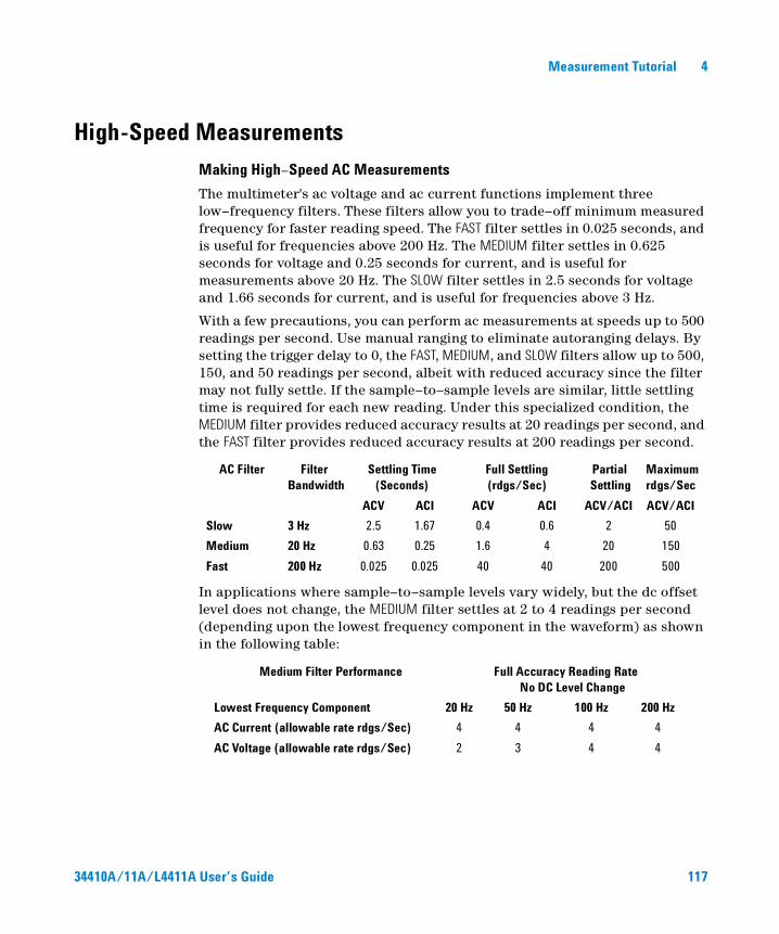
Measurement Tutorial 4
High-Speed Measurements
Making High–Speed AC Measurements
The multimeter's ac voltage and ac current functions implement three low–frequency filters. These filters allow you to trade–off minimum measured frequency for faster reading speed. The FAST filter settles in 0.025 seconds, and is useful for frequencies above 200 Hz. The MEDIUM filter settles in 0.625 seconds for voltage and 0.25 seconds for current, and is useful for measurements above 20 Hz. The SLOW filter settles in 2.5 seconds for voltage and 1.66 seconds for current, and is useful for frequencies above 3 Hz.
With a few precautions, you can perform ac measurements at speeds up to 500 readings per second. Use manual ranging to eliminate autoranging delays. By setting the trigger delay to 0, the FAST, MEDIUM, and SLOW filters allow up to 500, 150, and 50 readings per second, albeit with reduced accuracy since the filter may not fully settle. If the sample–to–sample levels are similar, little settling time is required for each new reading. Under this specialized condition, the MEDIUM filter provides reduced accuracy results at 20 readings per second, and the FAST filter provides reduced accuracy results at 200 readings per second.
In applications where sample–to–sample levels vary widely, but the dc offset level does not change, the MEDIUM filter settles at 2 to 4 readings per second (depending upon the lowest frequency component in the waveform) as shown in the following table:
AC Filter Filter Bandwidth
Settling Time (Seconds)
Full Settling (rdgs/Sec)
Partial Settling
Maximum rdgs/Sec
ACV ACI ACV ACI ACV/ACI ACV/ACI
Slow 3 Hz 2.5 1.67 0.4 0.6 2 50
Medium 20 Hz 0.63 0.25 1.6 4 20 150
Fast 200 Hz 0.025 0.025 40 40 200 500
Medium Filter Performance Full Accuracy Reading RateNo DC Level Change
Lowest Frequency Component 20 Hz 50 Hz 100 Hz 200 Hz
AC Current (allowable rate rdgs/Sec) 4 4 4 4
AC Voltage (allowable rate rdgs/Sec) 2 3 4 4
34410A/11A/L4411A User’s Guide 117
4 Measurement Tutorial
For ac voltage, additional settling time may be required when the dc level varies from sample to sample. The default sample delays allow for a dc level change of 3% of range for all filters. If the dc level change exceeds these levels, additional settling time is required. The multimeter's dc blocking circuitry has a settling time constant of 0.2 seconds. This settling time only affects measurement accuracy when dc offset levels vary from sample to sample. If maximum measurement speed is desired in a scanning system, you may want to add an external dc blocking circuit to those channels with significant dc voltages present. This circuit can be as simple as a resistor and a capacitor.
For ac current, additional settling time is not required when the dc level varies sample to sample.
Making High–Speed dc and Resistance Measurements
The multimeter incorporates an automatic zero measurement procedure (autozero) to eliminate internal thermal EMF and bias current errors. Each measurement actually consists of a measurement of the input terminals followed by a measurement of the internal offset voltage. The internal offset voltage error is subtracted from the input for improved accuracy. This compensates for offset voltage changes due to temperature. For maximum reading speed, turn autozero off. This will more than double your reading speeds for dc voltage, resistance, and dc current functions. Autozero does not apply to other measurement functions.
118 34410A/11A/L4411A User’s Guide
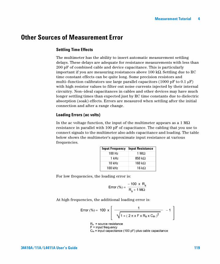
Measurement Tutorial 4
Other Sources of Measurement Error
Settling Time Effects
The multimeter has the ability to insert automatic measurement settling delays. These delays are adequate for resistance measurements with less than 200 pF of combined cable and device capacitance. This is particularly important if you are measuring resistances above 100 kΩ. Settling due to RC time constant effects can be quite long. Some precision resistors and multi–function calibrators use large parallel capacitors (1000 pF to 0.1 µF) with high resistor values to filter out noise currents injected by their internal circuitry. Non–ideal capacitances in cables and other devices may have much longer settling times than expected just by RC time constants due to dielectric absorption (soak) effects. Errors are measured when settling after the initial connection and after a range change.
Loading Errors (ac volts)
In the ac voltage function, the input of the multimeter appears as a 1 MΩ resistance in parallel with 100 pF of capacitance. The cabling that you use to connect signals to the multimeter also adds capacitance and loading. The table below shows the multimeter's approximate input resistance at various frequencies.
For low frequencies, the loading error is:
At high frequencies, the additional loading error is:
Input Frequency Input Resistance100 Hz 1 MΩ
1 kHz 850 kΩ 10 kHz 160 kΩ
100 kHz 16 kΩ
34410A/11A/L4411A User’s Guide 119
4 Measurement Tutorial
Measurements Below Full Scale
You can make the most accurate ac measurements when the multimeter is at or near the full scale of the selected range. Autoranging occurs at 10% (down–range) and 120% (up–range) of full scale. This enables you to measure some inputs at full scale on one range and 10% of full scale on the next higher range. In general, the accuracy is better on the lower range; for the highest accuracy, select the lowest manual range possible for the measurement.
High–Voltage Self–Heating Errors
If you apply more than 300 Vrms, self–heating occurs in the multimeter's internal signal–conditioning components. These errors are included in the multimeter's specifications.
Temperature changes inside the multimeter due to self–heating may cause additional error on other ac voltage ranges. The additional error is less than 0.02% and dissipates in a few minutes.
AC Current Measurement Errors (Burden Voltage)
Burden voltage errors, which apply to dc current, also apply to ac current measurements. However, the burden voltage for ac current is larger due to the multimeter's series inductance and your measurement connections. The burden voltage increases as the input frequency increases. Some circuits may oscillate when performing current measurements due to the multimeter's series inductance and your measurement connections.
Low–Level Measurement Errors
When measuring ac voltages less than 100 mV, be aware that these measurements are especially susceptible to errors introduced by extraneous noise sources. An exposed test lead acts as an antenna and a properly functioning multimeter will measure the signals received. The entire measurement path, including the power line, act as a loop antenna. Circulating currents in the loop create error voltages across any impedances in series with the multimeter's input. For this reason, you should apply low–level ac voltages to the multimeter through shielded cables. You should connect the shield to the input LO terminal.
Make sure the multimeter and the ac source are connected to the same electrical outlet whenever possible. You should also minimize the area of any ground loops that cannot be avoided. A high–impedance source is more
120 34410A/11A/L4411A User’s Guide
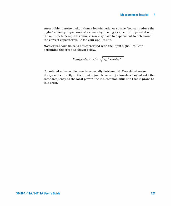
Measurement Tutorial 4
susceptible to noise pickup than a low–impedance source. You can reduce the high–frequency impedance of a source by placing a capacitor in parallel with the multimeter's input terminals. You may have to experiment to determine the correct capacitor value for your application.
Most extraneous noise is not correlated with the input signal. You can determine the error as shown below.
Correlated noise, while rare, is especially detrimental. Correlated noise always adds directly to the input signal. Measuring a low–level signal with the same frequency as the local power line is a common situation that is prone to this error.
34410A/11A/L4411A User’s Guide 121
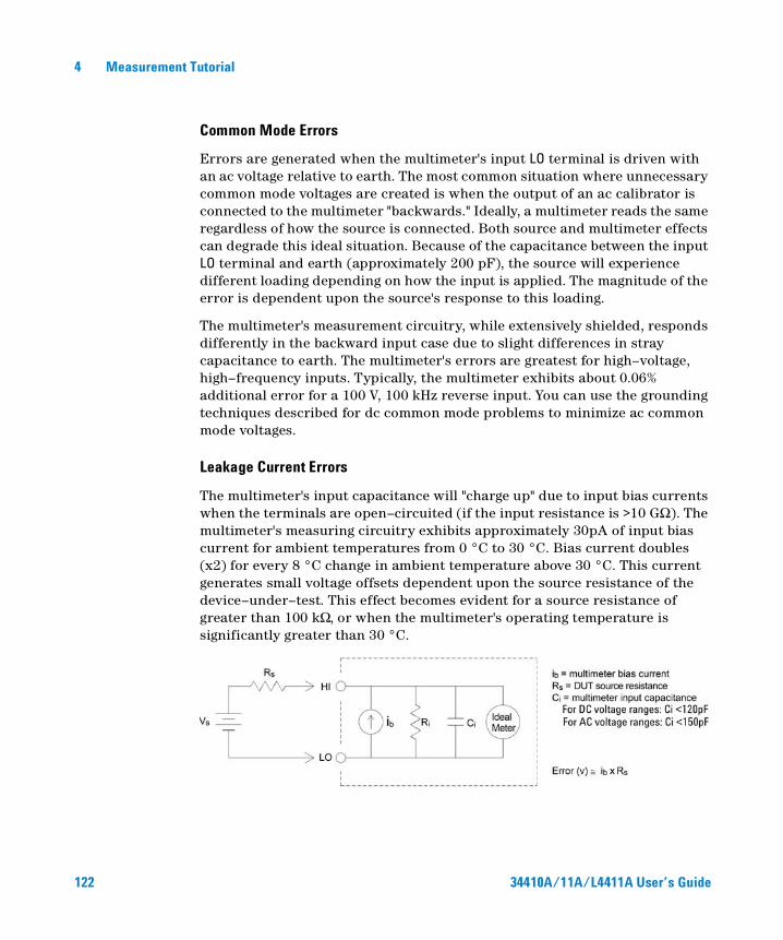
4 Measurement Tutorial
Common Mode Errors
Errors are generated when the multimeter's input LO terminal is driven with an ac voltage relative to earth. The most common situation where unnecessary common mode voltages are created is when the output of an ac calibrator is connected to the multimeter "backwards." Ideally, a multimeter reads the same regardless of how the source is connected. Both source and multimeter effects can degrade this ideal situation. Because of the capacitance between the input LO terminal and earth (approximately 200 pF), the source will experience different loading depending on how the input is applied. The magnitude of the error is dependent upon the source's response to this loading.
The multimeter's measurement circuitry, while extensively shielded, responds differently in the backward input case due to slight differences in stray capacitance to earth. The multimeter's errors are greatest for high–voltage, high–frequency inputs. Typically, the multimeter exhibits about 0.06% additional error for a 100 V, 100 kHz reverse input. You can use the grounding techniques described for dc common mode problems to minimize ac common mode voltages.
Leakage Current Errors
The multimeter's input capacitance will "charge up" due to input bias currents when the terminals are open–circuited (if the input resistance is >10 GΩ). The multimeter's measuring circuitry exhibits approximately 30pA of input bias current for ambient temperatures from 0 °C to 30 °C. Bias current doubles (x2) for every 8 °C change in ambient temperature above 30 °C. This current generates small voltage offsets dependent upon the source resistance of the device–under–test. This effect becomes evident for a source resistance of greater than 100 kΩ, or when the multimeter's operating temperature is significantly greater than 30 °C.
122 34410A/11A/L4411A User’s Guide
Agilent 34410A/11A/L4411A 6½ Digit MultimeterUser’s Guide
5Specifications
DC Characteristics 125
AC Characteristics 128
Frequency and Period Characteristics 130
Capacitance Characteristics 132
Temperature Characteristics 132
Additional 34411A/L4411A Specifications 133
Measurement and System Speeds 134
General Specifications (34410A/11A) 136
General Specifications (L4411A) 137
Dimensions 138
To Calculate Total Measurement Error 139
Interpreting Accuracy Specifications 141
Configuring for Highest Accuracy Measurements 142
123Agilent Technologies
5 Specifications
These specifications apply when using the 34410A/11A/L4411A multimeter in an environment that is free of electromagnetic interference and electrostatic charge.
When using the multimeter in an environment where electromagnetic interference or significant electrostatic charge is present, measurement accuracy may be reduced. Particularly note:
• The voltage measurement probes are not shielded and can act as antennas, causing electromagnetic interference to be added to the signal being measured.
• Electrostatic discharges of 4000 V or greater may cause the multimeter to temporarily stop responding, resulting in a lost or erroneous reading.
Specifications are subject to change without notice. For the latest specifications, see the product datasheet on the Web. Firmware updates may also be available on the Web. Start at either product page:
www.agilent.com/find/34410A
www.agilent.com/find/34411A
www.agilent.com/find/L4411A
NOTE The specifications on the following pages are valid for the Agilent 34410A, 34411A, and L4411A multimeters with firmware revision 2.05, or later.
124 34410A/11A/L4411A User’s Guide
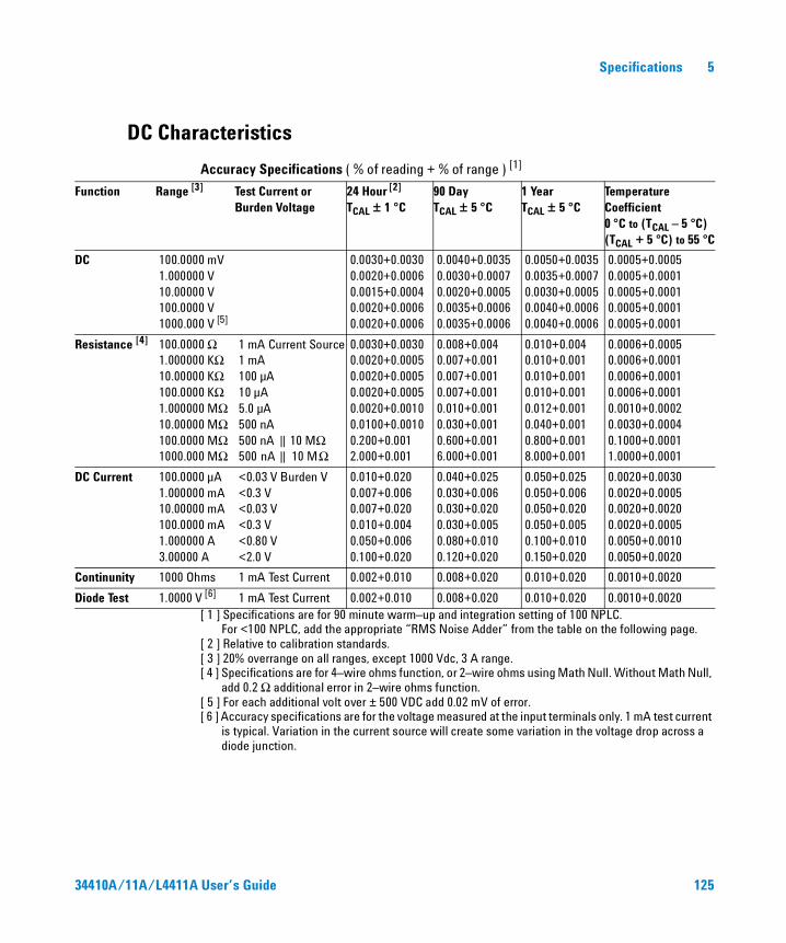
Specifications 5
DC Characteristics
Accuracy Specifications ( % of reading + % of range ) [1]
[ 1 ] Specifications are for 90 minute warm–up and integration setting of 100 NPLC. For <100 NPLC, add the appropriate “RMS Noise Adder” from the table on the following page.
[ 2 ] Relative to calibration standards.[ 3 ] 20% overrange on all ranges, except 1000 Vdc, 3 A range.[ 4 ] Specifications are for 4–wire ohms function, or 2–wire ohms using Math Null. Without Math Null,
add 0.2 Ω additional error in 2–wire ohms function.[ 5 ] For each additional volt over ± 500 VDC add 0.02 mV of error.[ 6 ] Accuracy specifications are for the voltage measured at the input terminals only. 1 mA test current
is typical. Variation in the current source will create some variation in the voltage drop across a diode junction.
Function Range [3] Test Current or Burden Voltage
24 Hour [2]
TCAL ± 1 °C90 DayTCAL ± 5 °C
1 YearTCAL ± 5 °C
Temperature Coefficient0 °C to (TCAL – 5 °C) (TCAL + 5 °C) to 55 °C
DC 100.0000 mV1.000000 V10.00000 V100.0000 V1000.000 V [5]
0.0030+0.00300.0020+0.00060.0015+0.00040.0020+0.00060.0020+0.0006
0.0040+0.00350.0030+0.00070.0020+0.00050.0035+0.00060.0035+0.0006
0.0050+0.00350.0035+0.00070.0030+0.00050.0040+0.00060.0040+0.0006
0.0005+0.00050.0005+0.00010.0005+0.00010.0005+0.00010.0005+0.0001
Resistance [4] 100.0000 Ω1.000000 KΩ10.00000 KΩ100.0000 KΩ1.000000 MΩ10.00000 MΩ100.0000 MΩ1000.000 MΩ
1 mA Current Source1 mA100 µA10 µA5.0 µA500 nA500 nA || 10 MΩ 500 nA || 10 MΩ
0.0030+0.00300.0020+0.00050.0020+0.00050.0020+0.00050.0020+0.00100.0100+0.00100.200+0.0012.000+0.001
0.008+0.0040.007+0.0010.007+0.0010.007+0.0010.010+0.0010.030+0.0010.600+0.0016.000+0.001
0.010+0.0040.010+0.0010.010+0.0010.010+0.0010.012+0.0010.040+0.0010.800+0.0018.000+0.001
0.0006+0.00050.0006+0.00010.0006+0.00010.0006+0.00010.0010+0.00020.0030+0.00040.1000+0.00011.0000+0.0001
DC Current 100.0000 µA1.000000 mA10.00000 mA100.0000 mA1.000000 A3.00000 A
<0.03 V Burden V<0.3 V<0.03 V<0.3 V<0.80 V<2.0 V
0.010+0.0200.007+0.0060.007+0.0200.010+0.0040.050+0.0060.100+0.020
0.040+0.0250.030+0.0060.030+0.0200.030+0.0050.080+0.0100.120+0.020
0.050+0.0250.050+0.0060.050+0.0200.050+0.0050.100+0.0100.150+0.020
0.0020+0.00300.0020+0.00050.0020+0.00200.0020+0.00050.0050+0.00100.0050+0.0020
Continunity 1000 Ohms 1 mA Test Current 0.002+0.010 0.008+0.020 0.010+0.020 0.0010+0.0020
Diode Test 1.0000 V [6] 1 mA Test Current 0.002+0.010 0.008+0.020 0.010+0.020 0.0010+0.0020
34410A/11A/L4411A User’s Guide 125

5 Specifications
Performance Versus Integration Time – 60Hz (50Hz) Power line frequency
[ 1 ] Resolution is defined as the typical 10 VDC range RMS noise.[ 2 ] Normal mode rejection for power–line frequency ± 0.1%.[ 3 ] Maximum rate for DCV, DCI, and 2–Wire resistance functions
(using zero settling delay, autozero off, etc.).[ 4 ] Autozero on for => 1 NPLC.
Basic dc accuracy specifications (previous page) include RMS noise at 100 NPLC. For <100 NPLC, add appropriate “RMS Noise Adder” to basic accuracy specification.
[ 5 ] For power–line frequency ± 1% 75 dB and for ± 3% 55 dB.[ 6 ] Only for 34411A/L4411A.
Transfer Accuracy (Typical)All DC volts, <0.12 A DC Current, < 1.2 MΩ: (24 hour % of range error) / 2)All other DC current and resistance: (24 hour % of range error + % of reading)/2Conditions: - Within 10 minutes and ±0.5 °C
- Within ±10% of initial value. - Following a 2–hour warm–up. - Fixed range. - Using >= 10 NPLC. - Measurements are made using accepted metrology practices.
RMS Noise Adder % range [4]
Integration Time Number of Power
Line Cycles (NPLC)
Resolution ppm Range [1]
NMR db [2] Readings / Second [3]
DCV10, 1000 V
DCV1, 100 V
Resistance1K, 10K ohm
DCV 0.1 V
Resistance100 ohm
DCI 1 amp
0.001 [6]
0.002 [6]
0.0060.020.060.21210
100
301563
1.50.70.30.20.1
0.03
000000
55110 [5]
110 [5]
110 [5]
50,00025,00010,00030001000300
60(50)30(25)
6(5)0.6(0.5)
0.00600.00300.00120.00060.00030.0002
0.00.00.00.0
0.01000.00600.00400.00300.00200.00150.00010.0001
0.00.0
0.10000.06000.06000.03000.02000.01500.00100.00100.0005
0.0
126 34410A/11A/L4411A User’s Guide
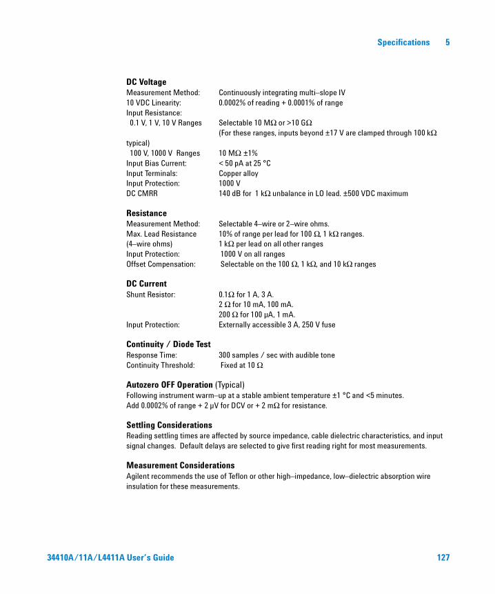
Specifications 5
DC VoltageMeasurement Method: Continuously integrating multi–slope IV10 VDC Linearity: 0.0002% of reading + 0.0001% of rangeInput Resistance:0.1 V, 1 V, 10 V Ranges Selectable 10 MΩ or >10 GΩ
(For these ranges, inputs beyond ±17 V are clamped through 100 kΩ typical)100 V, 1000 V Ranges 10 MΩ ±1%
Input Bias Current: < 50 pA at 25 °CInput Terminals: Copper alloyInput Protection: 1000 VDC CMRR 140 dB for 1 kΩ unbalance in LO lead. ±500 VDC maximum
ResistanceMeasurement Method: Selectable 4–wire or 2–wire ohms.Max. Lead Resistance 10% of range per lead for 100 Ω, 1 kΩ ranges. (4–wire ohms) 1 kΩ per lead on all other rangesInput Protection: 1000 V on all rangesOffset Compensation: Selectable on the 100 Ω, 1 kΩ, and 10 kΩ ranges
DC CurrentShunt Resistor: 0.1Ω for 1 A, 3 A.
2 Ω for 10 mA, 100 mA. 200 Ω for 100 µA, 1 mA.
Input Protection: Externally accessible 3 A, 250 V fuse
Continuity / Diode TestResponse Time: 300 samples / sec with audible toneContinuity Threshold: Fixed at 10 Ω
Autozero OFF Operation (Typical)Following instrument warm–up at a stable ambient temperature ±1 °C and <5 minutes.Add 0.0002% of range + 2 µV for DCV or + 2 mΩ for resistance.
Settling ConsiderationsReading settling times are affected by source impedance, cable dielectric characteristics, and input signal changes. Default delays are selected to give first reading right for most measurements.
Measurement ConsiderationsAgilent recommends the use of Teflon or other high–impedance, low–dielectric absorption wire insulation for these measurements.
34410A/11A/L4411A User’s Guide 127
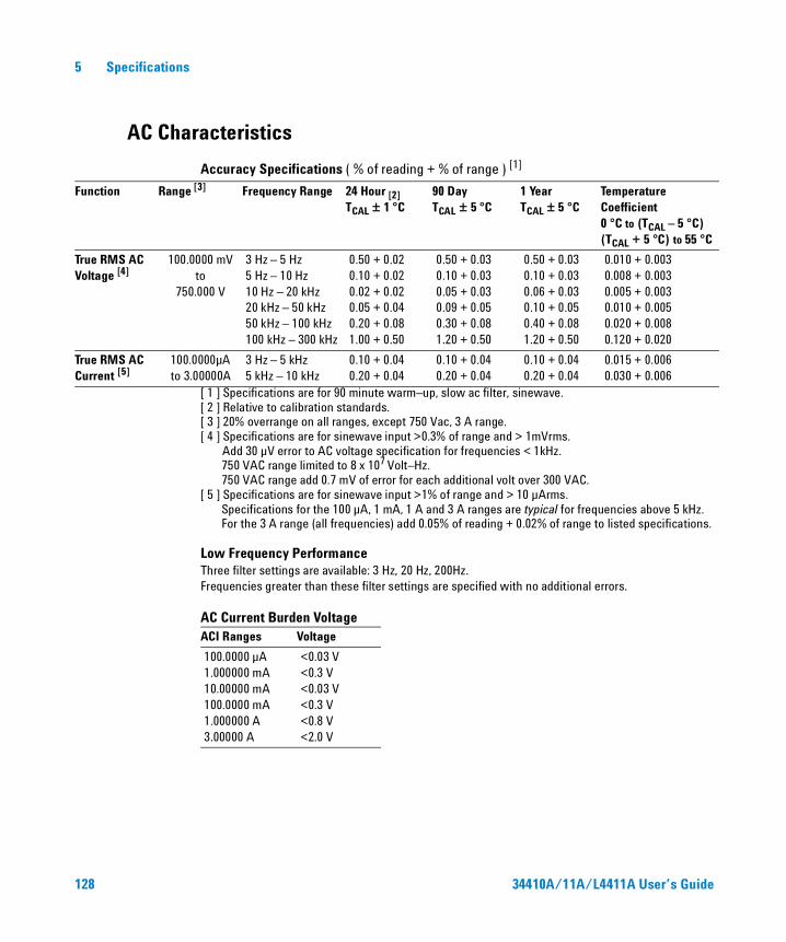
5 Specifications
AC Characteristics
Accuracy Specifications ( % of reading + % of range ) [1]
[ 1 ] Specifications are for 90 minute warm–up, slow ac filter, sinewave.[ 2 ] Relative to calibration standards.[ 3 ] 20% overrange on all ranges, except 750 Vac, 3 A range.[ 4 ] Specifications are for sinewave input >0.3% of range and > 1mVrms.
Add 30 µV error to AC voltage specification for frequencies < 1kHz.750 VAC range limited to 8 x 10⁷ Volt–Hz.750 VAC range add 0.7 mV of error for each additional volt over 300 VAC.
[ 5 ] Specifications are for sinewave input >1% of range and > 10 µArms. Specifications for the 100 µA, 1 mA, 1 A and 3 A ranges are typical for frequencies above 5 kHz. For the 3 A range (all frequencies) add 0.05% of reading + 0.02% of range to listed specifications.
Low Frequency PerformanceThree filter settings are available: 3 Hz, 20 Hz, 200Hz. Frequencies greater than these filter settings are specified with no additional errors.
AC Current Burden Voltage
Function Range [3] Frequency Range 24 Hour [2]TCAL ± 1 °C
90 DayTCAL ± 5 °C
1 YearTCAL ± 5 °C
Temperature Coefficient0 °C to (TCAL – 5 °C) (TCAL + 5 °C) to 55 °C
True RMS AC Voltage [4]
100.0000 mVto
750.000 V
3 Hz – 5 Hz5 Hz – 10 Hz10 Hz – 20 kHz20 kHz – 50 kHz50 kHz – 100 kHz100 kHz – 300 kHz
0.50 + 0.020.10 + 0.020.02 + 0.020.05 + 0.040.20 + 0.081.00 + 0.50
0.50 + 0.030.10 + 0.030.05 + 0.030.09 + 0.050.30 + 0.081.20 + 0.50
0.50 + 0.030.10 + 0.030.06 + 0.030.10 + 0.050.40 + 0.081.20 + 0.50
0.010 + 0.0030.008 + 0.0030.005 + 0.0030.010 + 0.0050.020 + 0.0080.120 + 0.020
True RMS AC Current [5]
100.0000µA to 3.00000A
3 Hz – 5 kHz5 kHz – 10 kHz
0.10 + 0.040.20 + 0.04
0.10 + 0.040.20 + 0.04
0.10 + 0.040.20 + 0.04
0.015 + 0.0060.030 + 0.006
ACI Ranges Voltage
100.0000 µA1.000000 mA10.00000 mA100.0000 mA1.000000 A3.00000 A
<0.03 V<0.3 V<0.03 V<0.3 V<0.8 V<2.0 V
128 34410A/11A/L4411A User’s Guide
Specifications 5
Voltage Transfer Accuracy ( typical )Frequency Error 10 Hz to 300 kHz (24 hour % of range + % of reading)/5
Conditions: - Sinewave input only using slow filter. - Within 10 minutes and ±0.5 °C. - Within ±10% of initial voltage and ±1% of initial frequency. - Following a 2–hour warm–up. - Fixed range between 10% and 100% of full scale (and <120 V). - Measurements are made using accepted metrology practices
True RMS AC VoltageMeasurement Type AC–coupled True RMS. Measures the AC component of the input.Measurement Method: Digital sampling with anti–alias filter.AC Common Mode Rejection
70 dB For 1 kΩ unbalanced in LO lead and <60 Hz. ±500 V peak maximum.Maximum Input: 400 Vdc, 1100 VpeakInput Impedance: 1 MΩ ± 2%, in parallel with <150 pFInput Protection: 750 V rms all ranges
True RMS AC CurrentMeasurement Type: Directly coupled to the fuse and shunt.
AC–coupled True RMS measurement (measure the AC component only).Measurement Method: Digital sampling with anti–alias filter.Maximum Input: The peak value of the DC + AC current must be <300% of range.
The RMS current <3 A including the DC current content.Shunt Resistor: 0.1 Ω for 1A, 3A,
2 Ω for 10 mA 100 mA, 200 Ω for 100 µA, 1 mA
Input Protection: Externally accessible 3A, 250 V fuse
Crest Factor and Peak InputCrest Factor: For <10:1 errors included.
Limited by peak input and 300 kHz bandwidth.Peak Input: 300% of Range. Limited by maximum inputOverload Ranging Will select higher range if peak input overload is detected during
auto range. Overload is reported in manual ranging.
Settling ConsiderationsDefault delays are selected to give first reading right for most measurements. The input blocking RC time constant must be allowed to fully settle before the most accurate measurements are possible.
34410A/11A/L4411A User’s Guide 129
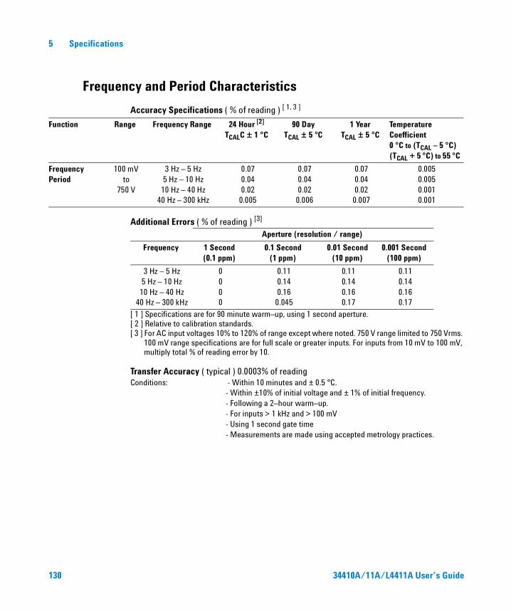
5 Specifications
Frequency and Period Characteristics
Accuracy Specifications ( % of reading ) [ 1, 3 ]
Additional Errors ( % of reading ) [3]
[ 1 ] Specifications are for 90 minute warm–up, using 1 second aperture.[ 2 ] Relative to calibration standards.[ 3 ] For AC input voltages 10% to 120% of range except where noted. 750 V range limited to 750 Vrms.
100 mV range specifications are for full scale or greater inputs. For inputs from 10 mV to 100 mV, multiply total % of reading error by 10.
Transfer Accuracy ( typical ) 0.0003% of readingConditions: - Within 10 minutes and ± 0.5 °C.
- Within ±10% of initial voltage and ± 1% of initial frequency. - Following a 2–hour warm–up. - For inputs > 1 kHz and > 100 mV - Using 1 second gate time - Measurements are made using accepted metrology practices.
Function Range Frequency Range 24 Hour [2]
TCALC ± 1 °C90 Day
TCAL ± 5 °C1 Year
TCAL ± 5 °CTemperature Coefficient0 °C to (TCAL – 5 °C) (TCAL + 5 °C) to 55 °C
FrequencyPeriod
100 mV to
750 V
3 Hz – 5 Hz5 Hz – 10 Hz
10 Hz – 40 Hz40 Hz – 300 kHz
0.070.040.02
0.005
0.070.040.02
0.006
0.070.040.02
0.007
0.0050.0050.0010.001
Aperture (resolution / range)
Frequency 1 Second(0.1 ppm)
0.1 Second(1 ppm)
0.01 Second(10 ppm)
0.001 Second(100 ppm)
3 Hz – 5 Hz5 Hz – 10 Hz10 Hz – 40 Hz
40 Hz – 300 kHz
0000
0.110.140.16
0.045
0.110.140.160.17
0.110.140.160.17
130 34410A/11A/L4411A User’s Guide
Specifications 5
Frequency and PeriodMeasurement Type: Reciprocal–counting technique. AC–coupled input using the AC voltage
measurement function.Input Impedance: 1 MΩ ±2%, in parallel with <150 pFInput Protection: 750 V rms all ranges
Measurement ConsiderationsAll frequency counters are susceptible to error when measuring low–voltage, low–frequency signals. Shielding inputs from external noise pickup is critical for minimizing measurement errors.
Settling ConsiderationsErrors will occur when attempting to measure the frequency or period of an input following a dc offset voltage change. The input blocking RC time constant must be allowed to fully settle ( up to 1 sec. ). before the most accurate measurements are possible.
34410A/11A/L4411A User’s Guide 131

5 Specifications
Capacitance Characteristics
Accuracy Specifications ( % of reading + % of range ) [1]
[ 1 ] Specifications are for 90 minute warm–up using Math Null. Additional errors may occur for non–film capacitors.
[ 2 ] Specifications are for 1% to 120% of range on the 1 nF range and 10% to 120% of range on all other ranges.
CapacitanceMeasurement Type: Current input with measurement of resulting ramp.Connection Type: 2 Wire
Temperature Characteristics
Accuracy Specifications [1]
[ 1 ] For total measurement accuracy, add temperature probe error
Examples (RTD probe, measurement within “Best Range”):
1.) Meter within TCAL ± 5 °C: Error = 0.06 oC + probe error
2.) Meter at TCAL + 10 °C: Error = 0.06 oC + (5 x 0.003 oC) + probe error = 0.075 oC + probe error
Function Range [2] Test Current 1 YearTCAL ± 5 °C
Temperature Coefficient 0 °C to (TCAL – 5 °C) (TCAL + 5 °C) to 55 °C
Capacitance 1 nF10 nF100 nF1 µF10 µF
500 nA1 µA10 µA100 µA1 mA
0.50 + 0.500.40 + 0.100.40 + 0.100.40 + 0.100.40 + 0.10
0.05 + 0.050.05 + 0.010.01 + 0.010.01 + 0.010.01 + 0.01
Function Probe Type Ro Best Range 1 YearTCAL ± 5 °C
Temperature Coefficient
0 °C to (TCAL – 5 °C) (TCAL + 5 °C) to 55 °C
Temperature RTD
Thermistor
from 49 Ω to 2.1 kΩ
N/A
–200 oC to 600 oC
–80 oC to 150 oC
0.06 oC
0.08 oC
0.003 oC
0.002 oC
132 34410A/11A/L4411A User’s Guide
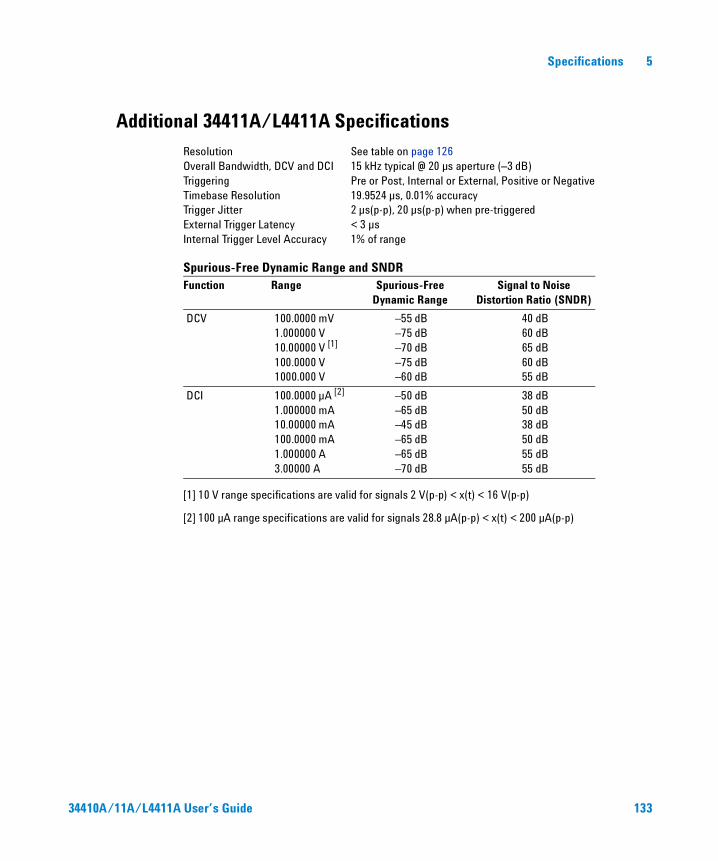
Specifications 5
Additional 34411A/L4411A Specifications
Resolution See table on page 126Overall Bandwidth, DCV and DCI 15 kHz typical @ 20 µs aperture (–3 dB)Triggering Pre or Post, Internal or External, Positive or NegativeTimebase Resolution 19.9524 µs, 0.01% accuracyTrigger Jitter 2 µs(p-p), 20 µs(p-p) when pre-triggeredExternal Trigger Latency < 3 µsInternal Trigger Level Accuracy 1% of range
Spurious-Free Dynamic Range and SNDR
[1] 10 V range specifications are valid for signals 2 V(p-p) < x(t) < 16 V(p-p)
[2] 100 µA range specifications are valid for signals 28.8 µA(p-p) < x(t) < 200 µA(p-p)
Function Range Spurious-FreeDynamic Range
Signal to Noise Distortion Ratio (SNDR)
DCV 100.0000 mV1.000000 V10.00000 V [1]
100.0000 V1000.000 V
–55 dB–75 dB–70 dB–75 dB–60 dB
40 dB60 dB65 dB60 dB55 dB
DCI 100.0000 µA [2]
1.000000 mA10.00000 mA100.0000 mA1.000000 A3.00000 A
–50 dB–65 dB–45 dB–65 dB–65 dB–70 dB
38 dB50 dB38 dB50 dB55 dB55 dB
34410A/11A/L4411A User’s Guide 133
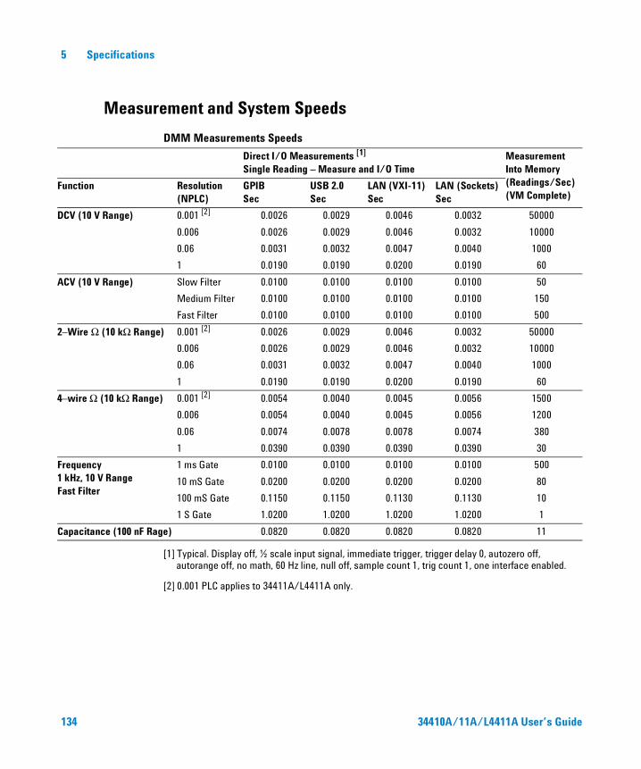
5 Specifications
Measurement and System Speeds
DMM Measurements Speeds
[1] Typical. Display off, ½ scale input signal, immediate trigger, trigger delay 0, autozero off, autorange off, no math, 60 Hz line, null off, sample count 1, trig count 1, one interface enabled.
[2] 0.001 PLC applies to 34411A/L4411A only.
Direct I/O Measurements [1]
Single Reading – Measure and I/O TimeMeasurement Into Memory(Readings/Sec)(VM Complete)
Function Resolution(NPLC)
GPIB Sec
USB 2.0Sec
LAN (VXI-11)Sec
LAN (Sockets)Sec
DCV (10 V Range) 0.001 [2] 0.0026 0.0029 0.0046 0.0032 50000
0.006 0.0026 0.0029 0.0046 0.0032 10000
0.06 0.0031 0.0032 0.0047 0.0040 1000
1 0.0190 0.0190 0.0200 0.0190 60
ACV (10 V Range) Slow Filter 0.0100 0.0100 0.0100 0.0100 50
Medium Filter 0.0100 0.0100 0.0100 0.0100 150
Fast Filter 0.0100 0.0100 0.0100 0.0100 500
2–Wire Ω (10 kΩ Range) 0.001 [2] 0.0026 0.0029 0.0046 0.0032 50000
0.006 0.0026 0.0029 0.0046 0.0032 10000
0.06 0.0031 0.0032 0.0047 0.0040 1000
1 0.0190 0.0190 0.0200 0.0190 60
4–wire Ω (10 kΩ Range) 0.001 [2] 0.0054 0.0040 0.0045 0.0056 1500
0.006 0.0054 0.0040 0.0045 0.0056 1200
0.06 0.0074 0.0078 0.0078 0.0074 380
1 0.0390 0.0390 0.0390 0.0390 30
Frequency 1 kHz, 10 V Range Fast Filter
1 ms Gate 0.0100 0.0100 0.0100 0.0100 500
10 mS Gate 0.0200 0.0200 0.0200 0.0200 80
100 mS Gate 0.1150 0.1150 0.1130 0.1130 10
1 S Gate 1.0200 1.0200 1.0200 1.0200 1
Capacitance (100 nF Rage) 0.0820 0.0820 0.0820 0.0820 11
134 34410A/11A/L4411A User’s Guide
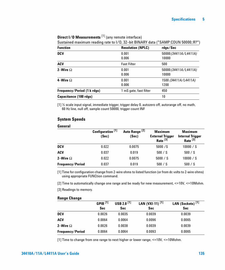
Specifications 5
Direct I/O Measurements [1] (any remote interface)Sustained maximum reading rate to I/O, 32–bit BINARY data ("SAMP:COUN 50000;:R?")
[1] ½ scale input signal, immediate trigger, trigger delay 0, autozero off, autorange off, no math, 60 Hz line, null off, sample count 50000, trigger count INF
System Speeds
General
[1] Time for configuration change from 2-wire ohms to listed function (or from dc volts to 2-wire ohms) using appropriate FUNCtion command.
[2] Time to automatically change one range and be ready for new measurement, <=10V, <=10Mohm.
[3] Readings to memory.
Range Change
[1] Time to change from one range to next higher or lower range, <=10V, <=10Mohm.
Function Resolution (NPLC) rdgs/Sec
DCV 0.001 0.006
50000 (34411A/L4411A) 10000
ACV Fast Filter 500
2–Wire Ω 0.001 0.006
50000 (34411A/L4411A) 10000
4–Wire Ω 0.001 0.006
1500 (34411A/L4411A) 1200
Frequency/Period (1 k rdgs) 1 mS gate, fast filter 450
Capacitance (100 rdgs) 10
Configuration [1]
(Sec)Auto Range [2]
(Sec)Maximum
External Trigger Rate [3]
Maximum Internal Trigger
Rate [3]
DCV 0.022 0.0075 5000 /S 10000 / S
ACV 0.037 0.019 500 / S 500 / S
2–Wire Ω 0.022 0.0075 5000 / S 10000 / S
Frequency/Period 0.037 0.019 500 / S 500 / S
GPIB [1]
SecUSB 2.0 [1]
SecLAN (VXI-11) [1]
SecLAN (Sockets) [1]
Sec
DCV 0.0026 0.0035 0.0039 0.0039
ACV 0.0064 0.0064 0.0096 0.0065
2–Wire Ω 0.0026 0.0038 0.0039 0.0039
Frequency/Period 0.0064 0.0064 0.0093 0.0065
34410A/11A/L4411A User’s Guide 135
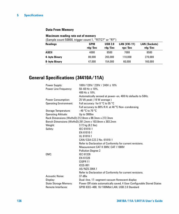
5 Specifications
Data From Memory
Maximum reading rate out of memory (Sample count 50000, trigger count 1, "FETC?" or "R?")
General Specifications (34410A/11A)
Power Supply: 100V/120V/ 220V / 240V ± 10%Power Line Frequency: 50–60 Hz ± 10%,
400 Hz ± 10%.Automatically sensed at power–on, 400 Hz defaults to 50Hz.
Power Consumption: 25 VA peak ( 16 W average )Operating Environment: Full accuracy for 0 °C to 55 °C
Full accuracy to 80% R.H. at 40 oC Non–condensingStorage Temperature: –40 °C to 70 °COperating Altitude: Up to 3000mRack Dimensions (WxHxD):212.8mm x 88.3mm x 272.3mmBench Dimensions (WxHxD):261.2mm x 103.8mm x 303.2mmWeight: 3.72 kg (8.2 lbs)Safety: IEC 61010-1
EN 61010-1UL 61010-1CAN/CSA-C22.2 No. 61010-1Refer to Declaration of Conformity for current revisions.Measurement CAT II 300V, CAT I 1000VPollution Degree 2
EMC: IEC 61326EN 61326CISPR 11ICES-001AS/NZS 2064.1 Refer to Declaration of Conformity for current revisions.
Acoustic Noise: 37 dBaDisplay: Dual–line, 17–segment vacuum florescent displayState Storage Memory: Power Off state automatically saved, 4 User Configurable Stored StatesRemote Interfaces: GPIB IEEE–488, 10/100Mbit LAN, USB 2.0 Standard
Readings GPIB rdg/Sec
USB 2.0rdg/Sec
LAN (VXI-11)rgs/Sec
LAN (Sockets)rdg/Sec
ASCII 4000 8500 7000 8500
4–byte Binary 89,000 265,000 110,000 270,000
8–byte Binary 47,000 154,000 60,000 160,000
136 34410A/11A/L4411A User’s Guide
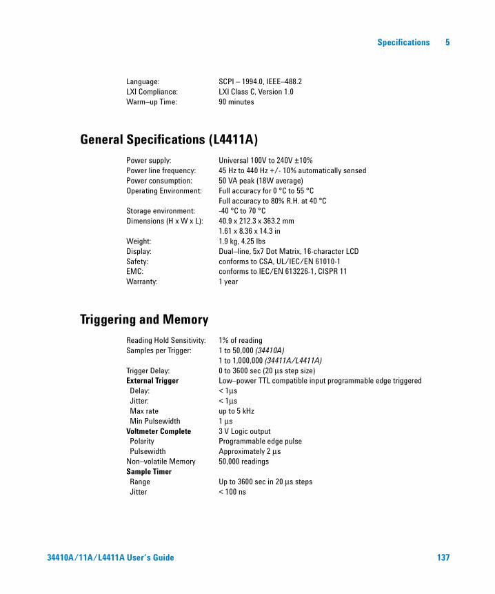
Specifications 5
Language: SCPI – 1994.0, IEEE–488.2LXI Compliance: LXI Class C, Version 1.0Warm–up Time: 90 minutes
General Specifications (L4411A)
Power supply: Universal 100V to 240V ±10%Power line frequency: 45 Hz to 440 Hz +/- 10% automatically sensedPower consumption: 50 VA peak (18W average)Operating Environment: Full accuracy for 0 °C to 55 °C
Full accuracy to 80% R.H. at 40 °CStorage environment: -40 °C to 70 °CDimensions (H x W x L): 40.9 x 212.3 x 363.2 mm
1.61 x 8.36 x 14.3 in Weight: 1.9 kg, 4.25 lbsDisplay: Dual–line, 5x7 Dot Matrix, 16-character LCDSafety: conforms to CSA, UL/IEC/EN 61010-1EMC: conforms to IEC/EN 613226-1, CISPR 11Warranty: 1 year
Triggering and Memory
Reading Hold Sensitivity: 1% of readingSamples per Trigger: 1 to 50,000 (34410A)
1 to 1,000,000 (34411A/L4411A) Trigger Delay: 0 to 3600 sec (20 µs step size)External Trigger Low–power TTL compatible input programmable edge triggeredDelay: < 1µsJitter: < 1µsMax rate up to 5 kHzMin Pulsewidth 1 µs
Voltmeter Complete 3 V Logic outputPolarity Programmable edge pulsePulsewidth Approximately 2 µs
Non–volatile Memory 50,000 readingsSample Timer Range Up to 3600 sec in 20 µs stepsJitter < 100 ns
34410A/11A/L4411A User’s Guide 137
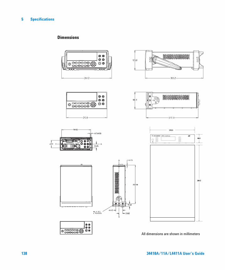
5 Specifications
Dimensions
All dimensions are shown in millimeters
212.3
363.2
40.9
138 34410A/11A/L4411A User’s Guide
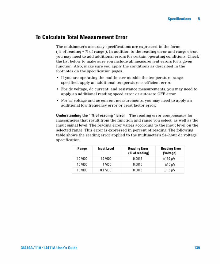
Specifications 5
To Calculate Total Measurement Error
The multimeter's accuracy specifications are expressed in the form: ( % of reading + % of range ). In addition to the reading error and range error, you may need to add additional errors for certain operating conditions. Check the list below to make sure you include all measurement errors for a given function. Also, make sure you apply the conditions as described in the footnotes on the specification pages.
• If you are operating the multimeter outside the temperature range specified, apply an additional temperature coefficient error.
• For dc voltage, dc current, and resistance measurements, you may need to apply an additional reading speed error or autozero OFF error.
• For ac voltage and ac current measurements, you may need to apply an additional low frequency error or crest factor error.
Understanding the " % of reading " Error The reading error compensates for inaccuracies that result from the function and range you select, as well as the input signal level. The reading error varies according to the input level on the selected range. This error is expressed in percent of reading. The following table shows the reading error applied to the multimeter's 24–hour dc voltage specification.
Range Input Level Reading Error (% of reading)
Reading Error (Voltage)
10 VDC 10 VDC 0.0015 ±150 µV
10 VDC 1 VDC 0.0015 ±15 µV
10 VDC 0.1 VDC 0.0015 ±1.5 µV
34410A/11A/L4411A User’s Guide 139

5 Specifications
Understanding the " % of range " Error The range error compensates for inaccuracies that result from the function and range you select. The range error contributes a constant error, expressed as a percent of range, independent of the input signal level. The following table shows the range error applied to the multimeter's 24–hour dc voltage specification.
Total Measurement Error To compute the total measurement error, add the reading error and range error. You can then convert the total measurement error to a "percent of input" error or a "ppm (parts–per–million) of input" error as shown below.
Error Example Assume that a 5 VDC signal is input to the multimeter on the 10 V range. Compute the total measurement error using the 90–day accuracy specifications: ± (0.0020% of reading + 0.0005% of range).
Reading Error = 0.0020% x 5 VDC = 100 µV
Range Error = 0.0005% x 10 VDC = 50 µV
Total Error = 100 µV + 50 µV = \150 µV= \0.003% of 5 VDC= \30 ppm of 5 VDC
Range Input Level Range Error (% of range)
Range Error (Voltage)
10 VDC 10 VDC 0.0004 ±40 µV
10 VDC 1 VDC 0.0004 ±40 µV
10 VDC 0.1 VDC 0.0004 ±40 µV
140 34410A/11A/L4411A User’s Guide
Specifications 5
Interpreting Accuracy Specifications
Transfer Accuracy
Transfer accuracy refers to the error introduced by the multimeter due to noise and short–term drift. This error becomes apparent when comparing two nearly–equal signals for the purpose of "transferring" the known accuracy of one device to the other.
24–Hour Accuracy
The 24–hour accuracy specification indicates the multimeter's relative accuracy over its full measurement range for short time intervals and within a stable environment. Short–term accuracy is usually specified for a 24–hour period and for a ±1 °C temperature range.
90–Day and 1–Year Accuracy
These long–term accuracy specifications are valid at the calibration temperature (Tcal) ± 5 °C temperature range. These specifications include the initial calibration errors plus the multimeter's long–term drift errors.
Temperature Coefficients
Accuracy is usually specified at the calibration temperature (Tcal) ± 5 °C temperature range. This is a common temperature range for many operating environments. You must add additional temperature coefficient errors to the accuracy specification if you are operating the multimeter outside the ± 5 °C temperature range (the specification is per °C).
34410A/11A/L4411A User’s Guide 141
5 Specifications
Configuring for Highest Accuracy Measurements
The measurement configurations shown below assume that the multimeter is in its power–on or reset state. It is also assumed that auto–ranging is enabled to ensure proper full scale range selection.
DC Voltage, DC Current, and Resistance Measurements:
• Select NPLC and 100 (NPLCs) for INTEGRATION.
• Set INPUT Z to HI–Z (for the 100 mV, 1 V, and 10 V ranges) for the best dc voltage accuracy.
• Use the 4–wire ohms function (Ω 4W) for the best resistance measurement accuracy.
• For 2–wire ohms, dc voltage and dc current measurements, set AUTOZERO to ON to remove thermal EMF and offset errors.
• Null the test lead resistance for 2–wire ohms measurements, and to remove any interconnection offset for dc voltage measurements.
AC Voltage and AC Current Measurements:
• Set the AC FILTER to 3 Hz: SLOW.
Frequency and Period Measurements:
• Set the GATE TIME to 1 sec.
142 34410A/11A/L4411A User’s Guide

Agilent 34401A/11A/L4411A 6½ Digit Multimeter User’s Guide
6Appendix: Firmware and Driver UpdatesFirmware and (IVI-COM) driver updates for the 34410A/11A multimeters are available via the Web. This section contains information for locating and downloading the updates to your computer.
Downloading the Update Utility and Firmware 144
Downloading IVI-COM Driver Updates 147
NOTE For firmware and driver update information specific to the L4411A, refer to the L4411A Getting Started Guide (p/n L4411-90001).
143Agilent Technologies

6 Appendix: Firmware and Driver Updates
Downloading the Update Utility and Firmware
Agilent 34410A/11A firmware updates are installed in the instrument using the Agilent Firmware Update Utility. The utility and firmware file can be found on the Web at:
www.agilent.com/find/34410Aor
www.agilent.com/find/34411A
Once this page is displayed, click on ‘Technical Support’ under the heading “More Details”. From the Technical Support window, scroll to ‘Drivers and Software’ and select:
√ 3341xA Firmware Update Revision < x.xx >
√ Documents & Downloads
√ Agilent 34410A/11A Firmware Update Utility
If the firmware update utility is not currently installed on your PC, open and install the utility from the Web site. The utility is saved in the default directory C:\Program Files\Agilent\Firmware Update Utility.
Downloading and Installing the Firmware Update
Return to the Web page and under “Documents & Downloads and select:
3441xA Firmware Update Revision < x.xx >
‘Open’ or ‘Save’ the firmware file to download it to your PC. Note the directory location as you will need to specify the path to the (firmware) file when you run the update utility.
144 34410A/11A/L4411A User’s Guide

Appendix: Firmware and Driver Updates 6
1. From the directory where the update utility was installed, start the utility by selecting FirmwareUpdateUtility.exe. Select ‘Next’ until the window shown in Figure A-1 appears.
Figure A-1. Firmware Update Utility File Selection Window.
2. Using the ‘Browse’ button, specify the path to the firmware file. Once speci-fied, the instrument model number will appear in the ‘Applicable Model’ win-dow along with the revision and instrument description. Select ‘Next’.
NOTE Depending on the interface to the 34410A or 34411A, the firmware update utility will require the instrument’s LAN address, GPIB address, or USB address/alias. Note this address before starting the utility.
34410A/11A/L4411A User’s Guide 145
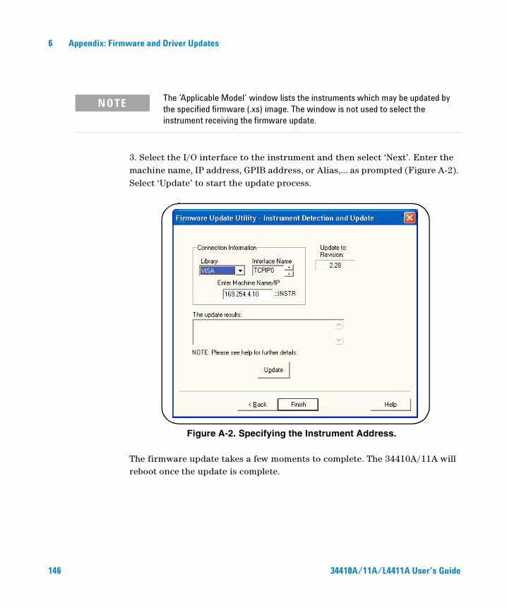
6 Appendix: Firmware and Driver Updates
3. Select the I/O interface to the instrument and then select ‘Next’. Enter the machine name, IP address, GPIB address, or Alias,... as prompted (Figure A-2). Select ‘Update’ to start the update process.
Figure A-2. Specifying the Instrument Address.
The firmware update takes a few moments to complete. The 34410A/11A will reboot once the update is complete.
NOTE The ‘Applicable Model’ window lists the instruments which may be updated by the specified firmware (.xs) image. The window is not used to select the instrument receiving the firmware update.
146 34410A/11A/L4411A User’s Guide
Appendix: Firmware and Driver Updates 6
Downloading IVI-COM Driver Updates
An IVI-COM driver for the 34410A/11A is provided on the Product Reference CD-ROM (p/n 34410-13601). Updates to the IVI-COM driver can be found on the Web at:
www.agilent.com/find/34410Aor
www.agilent.com/find/34411A
Once this page is displayed, click on ‘Technical Support’ under the heading “More Details”. From the Technical Support window, scroll to ‘Drivers and Software’ and select:
√ Instrument Drivers
√ Starts with 3 Download Agilent drivers for instruments that start with 3
√ Agilent 34410A Digital Multimeter, 6.5 Digitor
√ Agilent 34411A Digital Multimeter, 6.5 Digit
Select “Download” to install the driver. Additional information is provided by the ‘More Information’ link next to the ‘Download’ link.
34410A/11A/L4411A User’s Guide 147

6 Appendix: Firmware and Driver Updates
148 34410A/11A/L4411A User’s Guide

Index
Numerics1-Year Specifications, 14124-hour accuracy, 14134410A, 7
firmware updates 14434411A, 7
firmware updates 14490-Day Specifications, 141
AAC Current Measurements, 25
Configuring, 45Configuring for Accuracy, 142Errors In, 120
AC Filter, 45, 46, 54, 55AC Voltage Measurements
Configuring, 45Configuring for Accuracy, 142Errors In, 106High Speed, 117Loading Errors, 119Specifications, 128
AC Volts Measurements, 24Accuracy, 142Accuracy Specification Explained, 139Annunciators, 40Aperture, 52Auto Triggering, 68Auto Zero, 44, 45, 46, 56Auto-IP, 92Automatic Trigger Delay, 73Autoranging, 57Average Value, 65
BBandwidth, 22, 42, 54Beeper, 61Bumper Removal, 34Burden Voltage, 120Bus Triggering, 70
CCable Capacitance, 119Calibration, 84Calibration Errors, 122Capacitance Measurements, 28
Configuring, 47Errors In, 113Specifications, 132
Carrry Handle, 33Changing Digits Displayed, 22, 42Character Entry, 43Configuring
LAN, 91USB, 90
Connectors on Rear Panel, 9Continuity Tests, 47
DData Logger, 78dB Measurements, 63dBm Measurements, 64DC Current Measurements, 25
Configuring, 44Configuring for Accuracy, 142Errors In, 112
DC Voltage MeasurementsConfiguring, 44Configuring for Accuracy, 142Errors In, 101Hih Speed, 118Integration Integration Time, 51Loading Error, 101Specifications, 125Thermal EMF Error, 101
DC Volts Measurement, 24Declaration of Conformity, 6Default Gateway, 94Default Settings, 85Delay (triggering), 72Description, 7DHCP, 91Digit Masking, 22, 42Diode Test, 30Diode Tests, 47Display, 38
Character Entry, 43Shortcuts, 22, 42Turn Off, 41
Display Annunciators, 40Display Options, 41DNS Server, 91, 95downloading firmware updates 144downloading the IVI-COM driver 147
EError Conditions, 83errors
reading, 84EXT TRIG Terminal, 75External Triggering, 75
34410A/11A/L4411A User’s Guide 149
Index
FFactory Settings, 85firmware updates
downloads 144installation 144update utility 144
Frequency Measurements, 27Configuring, 46Configuring for Accuracy, 142Errors In, 112Specifications, 130
Front Panel Description, 8, 10Front Panel Display, 38Front Panel Keys, 21Front/Rear Terminal Switch, 49Fuse, 31
Power Line, 32
GGate Time, 22, 42, 46, 55GPIB Interface, 89Ground Loops, 103
HHigh Speed Measurements, 117High Voltage Self-Heating Error, 120Host Name, 94
IIEEE-488, 89IMMediate Triggering, 69Input Impedance, 44, 53Integration, 44, 45, 46INtegration Time, 22, 42Integration TIme, 102Integration Time, 51INTernal Triggering, 70IP Address, 92IVI-COM
driver updates 147
KKeys, 8, 10, 21
LLAN Interface, 88, 91Leakage Current, 122Limit TEsting, 62Limit Testing, 66Loading Errors, 101, 119
MMagnetic Loop Noise, 103Manual Ranging, 57MAth Functions
dB Measurements, 63Math Functions, 62
dBm, 64Limit Testing, 66Statistics, 65
Maximum Value, 65Measure
2-Wire Ohms, 264-wire Ohms, 26AC Current, 25AC Volts, 24Capacitance, 28DC Current, 25DC Volts, 24Diode Test, 30Frequency, 27Period, 27Resistance, 26Temperature, 29
Measurement Error, 139Below Full Scale, 120Burden Voltage, 120Common Mode, 122Ground Loops, 103High Resistance Measurements, 105Leakage Current, 122Loading, 119Loadiong Errors, 101Low Level Measurments, 120Magnetic Loops, 103Noise, 102Power Dissipation, 105Self-Heating, 120Test Lead Resistance, 105Thermal EMF, 101
Menus, 38Messages Displayed, 38Minimum Value, 65Multimeter
Failure to Turn On, 31Front Panel Keys, 21Fuse, 31Preparing for Use, 20Rack Mounting, 34Reset, 50Supplied Items, 20Triggering, 67
NNMR, 102Noise, 102, 103, 120Non-volatile Memory, 85NPLC, 51Null, 44, 45, 46, 47, 59Null Measurements, 59
OOffset Compensation, 45, 46
150 34410A/11A/L4411A User’s Guide
Index
PPeriod Measurements, 27
Configuring, 46Configuring for Accuracy, 142Errors In, 112Specifications, 130
Power Dissipation, 105Power LIne Noise, Rejecting, 102Power On State, 85Prepare for Use, 20Pre-Trigger Samples, 71Probe Type, 46
RRack Mounting, 34Radix Character, 60Range, 44, 45, 46, 47, 57Reading Hold, 69Rear Panel Description, 9Relative Measurements, 59remote
unexpected, 95Remote Annunciator, 88remote I/O
introduction, 88Remote Interface Configuration, 88Replacing the Power Line Fuse, 32Reset, 50Resistance Measurements, 26
Configuring, 45Configuring for Accuracy, 142Errors In, 104High Resistance Errors, 105High Speed, 118Integration Time, 51NPLC, 51Settling Time Errors, 119
Rubber Bumper Removal, 34
SSafety Information, 3Safety Notices, 2
Safety Symbols, 3Sample Count, 65Samples per Trigger, 71SCPI
Commands, 37Language Conventions, 37Language Version, 37
Second Display, 41Selecting Front or Rear Terminals, 49Self-Test, 82Setting
AC Filter, 45, 46Auto Zero, 44, 45, 46Beeper, 61Centigrade, 47Fahrenheit, 47Gate Time, 46Input IMpedance, 44Integration Time, 44, 45, 46Kelvin, 47NPLC, 44, 45, 46Null, 44, 45, 46, 47Offset Comp, 45, 46Probe Type, 46Radix Character, 60Range, 44, 45, 46, 47, 57Temperature Units, 47
Settling Time, 54, 119Single Triggering, 68Software Triggering, 70Specifications, 124, 141
1-year, 14124-hour accuracy, 14190-day, 141Transfer Accuracy, 141
Specifications Explained, 139Standard Deviation, 65State Storage, 48Statistics, 62, 65Store State, 48Subnet Mask, 91System II Rack Mounts, 34System Memory, 48System Operations, 82
System Specifications, 136
TTCP/IP, 93Temperature Coefficients (and
Accuiracy), 141Temperature Measurements, 29
Configuring, 46Errors In, 115NPLC, 51Units, 47
Test Lead Resistance, 105Test Limits, 66Thermal EMF Errors, 101Thousands Seperator, 60Transfer Accuracy, 141Triggering, 67
Auto Triggering, 68Automatic Delay, 73Bus, 70Delay, 72External, 75, 77Falling Edge, 77Immediate, 69Internal, 70Pre-Trigger Samples, 71Reading Hold, 69Rising Edge, 77Samples Per Trigger, 71Single, 68Slope, 77Software, 70Source, 67
Troubleshooting, 31True RMS, 106Turn Off Display, 41
UUSB Interface, 88, 90
VVM Complete, 75
34410A/11A/L4411A User’s Guide 151
Index
WWaste Electrical and Electronic Equipment
Directive, 5Web Browser, 98Web Password, 91, 95
152 34410A/11A/L4411A User’s Guide