ece 497 capstone design will barrett asato tashiro adam anderson
TRANSCRIPT

ECE 497Capstone Design
Will Barrett Asato Tashiro Adam Anderson

Purpose of the System
• The purpose is to create a scanning system to determine the location and size of metal fragments in a medium density fiber panel.

Background Information• The Weapons Integration & Development Directorate of
the US Army Aviation and Missile Research, Development, & Engineering Center performs a variety of munitions and warhead test programs– Known as the “AMRDEC”– Patrick Taylor is our sponsor
• They use bundles of fiber panels to capture shrapnel from the explosions
• Each bundle is then searched BY HAND to recover fragments, tabulate the X/Y position, and mass for each panel– The panel location is used to determine the depth of the
fragment

Background Information (cont’d)• The process can take up to 100 man hours PER PANEL• Each experiment could require up to 96 panels, or 9600 man-
hours per experiment• Removal is done outside on the test range
– Personnel have to be in protective clothing – Fragments are bagged by weight– Fragments have to be cleaned and decontaminated for safe handling
• Fragments are typically steel, but some tests use titanium or aluminum
• Data derived from the analysis is tabulated in a spreadsheet format, with the fragment designation, count, bundle and panel number, X/Y location, and size/weight

Fragment Set Weight Distribution
Totals\Wt Range <.25g .25g - .75g .75g - 2g 2g - 5g 5g - 7g 7g - 10g 10+gQuantity 235 272 271 157 19 7 3
Total Wt. (g) 34.185 130.017 346.711 467.746 109.794 64.433 32.659Avg. Wt. (g) 0.145 0.478 1.279 2.979 5.779 8.919 10.886
% of Total Captured Wt. 2.89% 10.99% 29.29% 39.52% 39.52% 9.28% 2.76%
STEEL WARHEAD FRAGMENT SETFOR FRAG BUNDLE SCANNER TESTING

Typical Fragment Morphology

Project Objective
• Automate analysis procedures to the maximum degree feasible – Analysis of X/Y location goal is 15 minutes/panel
• Portability – system can be setup by 1 person• Battery operated equipment is desirable

Measurement Parameters
• X/Y resolution of .5”• Minimum fragment detection of .25g

Approach
• Demonstrate a proof-of-concept capability that can be scaled up at a later time
• Use commercial-off-the-shelf (COTS) equipment to produce a gray-scale image of the fragments contained in a panel
• Process image to identify the centroid of each fragment and X/Y location – Output .csv file with the fragment location data

COTS Imaging Systems
• Ground Penetrating Radar (GPR)
• Industrial Radiography

What is Ground Penetrating Radar?
• GPR is a non-destructive imaging method that uses radar pulses to image the subsurface
• The radar pulses used are in the microwave band of the radio spectrum

How does GPR work?
• GPR is similar to a metal detector• The GPR system sends out thousands of RF frequency
pulses into the ground • The frequencies that are reflected back return to the
antennae• Frequency analysis of the reflected RF energy allows
correlation of different material compositions in the subsurface

GPR Schematic

Typical Applications
• Pipe Locating• Archeology• IED Locating (Improvised Explosive Devices)• Quality control of reinforced concrete

Ground Penetrating Radar

GPR Scans

Describing Industrial Radiography
• Industrial Radiography is also a non-destructive detection method which utilizes X-rays and gamma rays to view materials

How Industrial Radiography Works
• Similar to medical radiography, Industrial radiography uses an X-ray source to bombard a sample with high-energy radiation onto a film or a digital detector
• This creates a 2D image of the different materials in the sample.

Radiography Schematic

Typical Applications
• Security• Medical Imaging• Non-Destructive Testing– Castings– Welds

Medical X-Ray Radiography
X-Ray Source
Imaging Surface
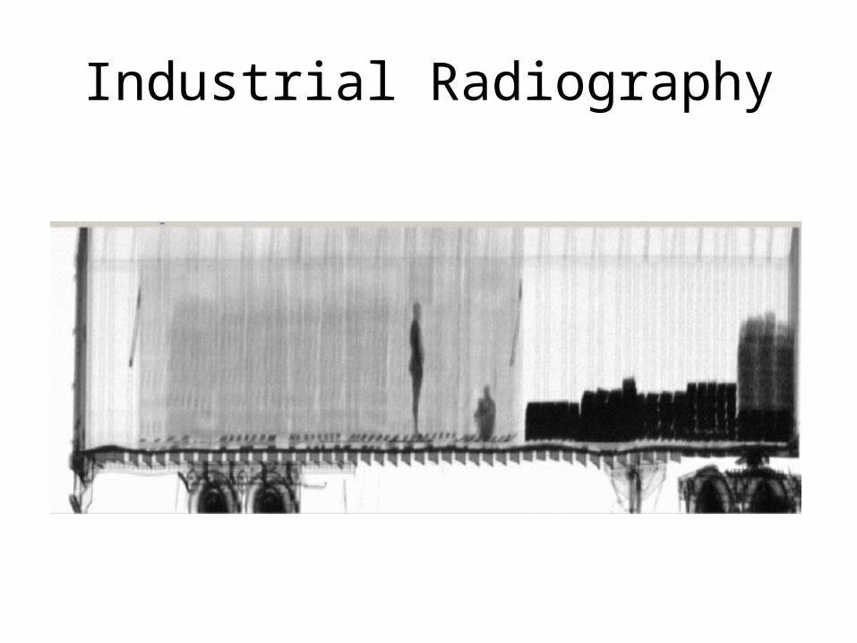
Industrial Radiography

• (Insert pic of Xerox)

Program Plan
• Contact vendors– Image dummy panels using radiography and GPR– Utilize 2D images for image processing study
• Image Processing Approach– 2D grayscale image can be processed using
MATLAB to determine the centroid and area of each fragment
– Tabulate fragments by area and X/Y location

Current Status
• Dummy panels have been fabricated• They will be shipped/delivered to USRadar,
Hayes, ATS, and University Hospital this week• Start analysis of our simulated fragment panel
this week

Simulated Fragment Panel

Simulated Fragment PanelBlack and White

Simulated Panel with Border Detection
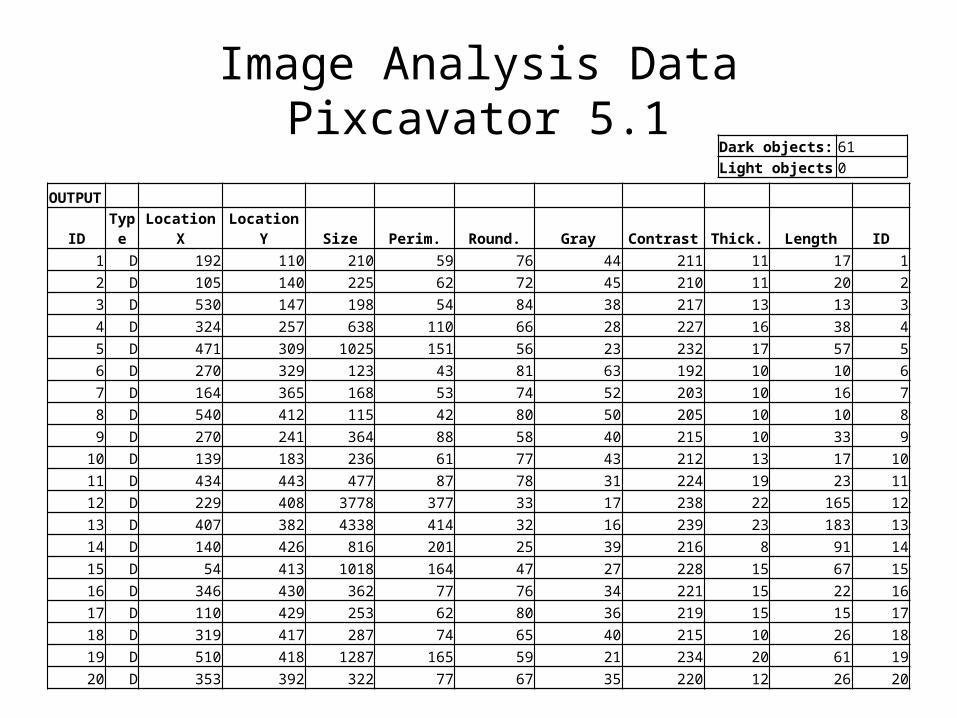
Image Analysis DataPixcavator 5.1
OUTPUT ID Type Location X Location Y Size Perim. Round. Gray Contrast Thick. Length ID
1 D 192 110 210 59 76 44 211 11 17 12 D 105 140 225 62 72 45 210 11 20 23 D 530 147 198 54 84 38 217 13 13 34 D 324 257 638 110 66 28 227 16 38 45 D 471 309 1025 151 56 23 232 17 57 56 D 270 329 123 43 81 63 192 10 10 67 D 164 365 168 53 74 52 203 10 16 78 D 540 412 115 42 80 50 205 10 10 89 D 270 241 364 88 58 40 215 10 33 9
10 D 139 183 236 61 77 43 212 13 17 1011 D 434 443 477 87 78 31 224 19 23 1112 D 229 408 3778 377 33 17 238 22 165 1213 D 407 382 4338 414 32 16 239 23 183 1314 D 140 426 816 201 25 39 216 8 91 1415 D 54 413 1018 164 47 27 228 15 67 1516 D 346 430 362 77 76 34 221 15 22 1617 D 110 429 253 62 80 36 219 15 15 1718 D 319 417 287 74 65 40 215 10 26 1819 D 510 418 1287 165 59 21 234 20 61 1920 D 353 392 322 77 67 35 220 12 26 20
Dark objects: 61Light objects 0