dupont(tm) suva(r) refrigerants: technical reference manual · tioning and refrigeration equipment....
TRANSCRIPT
Technical Information
DuPont™ Suva® Refrigerants:Technical Reference Manual
ART-41
DuPont™ Suva®
refrigerants
Table of ContentsIntroduction ................................................................................................................... 1
Options for Servicing Existing Equipment ................................................................. 1
Suva® Refrigerants Selection Guide ............................................................................ 2
Lubricants ..................................................................................................................... 3Retrofit to an HCFC refrigerant ..................................................................................... 3Retrofit to an HFC refrigerant with POE lubricant .......................................................... 4Lubricant selection ........................................................................................................ 4
Filter Driers .................................................................................................................... 4
Service Tips ................................................................................................................... 5
Retrofit Troubleshooting Guide ................................................................................... 7
Pressure/Temperature Relationships .........................................................................10Temperature glide ........................................................................................................10Superheat calculation ...................................................................................................12Subcool calculation ......................................................................................................12Average evaporator and condenser temperature calculation .......................................12
Expansion Devices ......................................................................................................13TXV operation ..............................................................................................................13Constant pressure expansion valves ............................................................................15Retrofitting TXV systems ..............................................................................................15
Safety and Handling Considerations ..........................................................................20Flammability .................................................................................................................20Decomposition .............................................................................................................20Inhalation toxicity ..........................................................................................................21Mechanical equipment room requirements ..................................................................22Skin and eye contact ....................................................................................................22Pressure and cylinder safety ........................................................................................22General precautions for handling Suva® refrigerants ....................................................23
Recovery, Reclamation, and Recycle .........................................................................23Responsible use ..........................................................................................................23Recovery ......................................................................................................................24Reclamation .................................................................................................................24Recycle ........................................................................................................................24Disposal .......................................................................................................................24
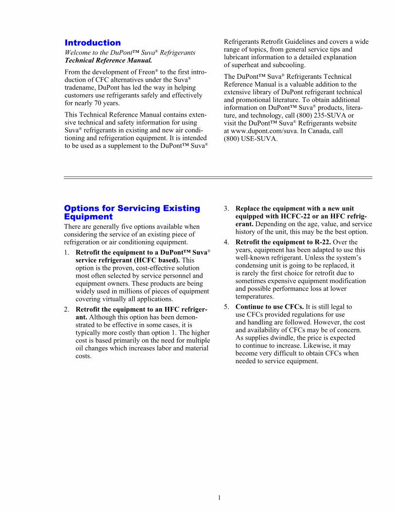
IntroductionWelcome to the DuPont™ Suva® RefrigerantsTechnical Reference Manual.From the development of Freon® to the first intro-duction of CFC alternatives under the Suva®
tradename, DuPont has led the way in helpingcustomers use refrigerants safely and effectivelyfor nearly 70 years.This Technical Reference Manual contains exten-sive technical and safety information for usingSuva® refrigerants in existing and new air condi-tioning and refrigeration equipment. It is intendedto be used as a supplement to the DuPont™ Suva®
1
Refrigerants Retrofit Guidelines and covers a widerange of topics, from general service tips andlubricant information to a detailed explanationof superheat and subcooling.The DuPont™ Suva® Refrigerants TechnicalReference Manual is a valuable addition to theextensive library of DuPont refrigerant technicaland promotional literature. To obtain additionalinformation on DuPont™ Suva® products, litera-ture, and technology, call (800) 235-SUVA orvisit the DuPont™ Suva® Refrigerants websiteat www.dupont.com/suva. In Canada, call(800) USE-SUVA.
Options for Servicing ExistingEquipmentThere are generally five options available whenconsidering the service of an existing piece ofrefrigeration or air conditioning equipment.1. Retrofit the equipment to a DuPont™ Suva®
service refrigerant (HCFC based). Thisoption is the proven, cost-effective solutionmost often selected by service personnel andequipment owners. These products are beingwidely used in millions of pieces of equipmentcovering virtually all applications.
2. Retrofit the equipment to an HFC refriger-ant. Although this option has been demon-strated to be effective in some cases, it istypically more costly than option 1. The highercost is based primarily on the need for multipleoil changes which increases labor and materialcosts.
3. Replace the equipment with a new unitequipped with HCFC-22 or an HFC refrig-erant. Depending on the age, value, and servicehistory of the unit, this may be the best option.
4. Retrofit the equipment to R-22. Over theyears, equipment has been adapted to use thiswell-known refrigerant. Unless the system’scondensing unit is going to be replaced, itis rarely the first choice for retrofit due tosometimes expensive equipment modificationand possible performance loss at lowertemperatures.
5. Continue to use CFCs. It is still legal touse CFCs provided regulations for useand handling are followed. However, the costand availability of CFCs may be of concern.As supplies dwindle, the price is expectedto continue to increase. Likewise, it maybecome very difficult to obtain CFCs whenneeded to service equipment.
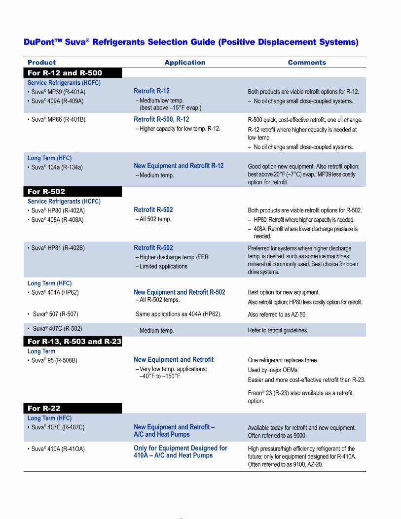
DuPont™ Suva® Refrigerants Selection Guide (Positive Displacement Systems)
2
Product Application CommentsFor R-12 and R-500Service Refrigerants (HCFC)• Suva® MP39 (R-401A)• Suva® 409A (R-409A)
Retrofit R-12– Medium/low temp.
(best above –15°F evap.)
Both products are viable retrofit options for R-12.– No oil change small close-coupled systems.
Retrofit R-500, R-12– Higher capacity for low temp. R-12.
R-500 quick, cost-effective retrofit; one oil change.R-12 retrofit where higher capacity is needed atlow temp.– No oil change small close-coupled systems.
Long Term (HFC)• Suva® 134a (R-134a) New Equipment and Retrofit R-12
– Medium temp.Good option new equipment. Also retrofit option;best above 20°F (–7°C) evap.; MP39 less costlyoption for retrofit.
For R-502Service Refrigerants (HCFC)• Suva® HP80 (R-402A)• Suva® 408A (R-408A)
Retrofit R-502– All 502 temp.
Both products are viable retrofit options for R-502.– HP80: Retrofit where higher capacity is needed.– 408A: Retrofit where lower discharge pressure is
needed.
• Suva® HP81 (R-402B) Retrofit R-502– Higher discharge temp./EER– Limited applications
Preferred for systems where higher dischargetemp. is desired, such as some ice machines;mineral oil commonly used. Best choice for opendrive systems.
Long Term (HFC)• Suva® 404A (HP62) New Equipment and Retrofit R-502
– All R-502 temps.
Same applications as 404A (HP62).
– Medium temp.
Best option for new equipment.Also retrofit option; HP80 less costly option for retrofit.
• Suva® 507 (R-507)
• Suva® 407C (R-502)
Also referred to as AZ-50.
Refer to retrofit guidelines.
For R-13, R-503 and R-23Long Term• Suva® 95 (R-508B) New Equipment and Retrofit
– Very low temp. applications:–40°F to –150°F
One refrigerant replaces three.Used by major OEMs.Easier and more cost-effective retrofit than R-23.
Freon® 23 (R-23) also available as a retrofitoption.
For R-22Long Term (HFC)• Suva® 407C (R-407C)
• Suva® 410A (R-41OA)
New Equipment and Retrofit –A/C and Heat Pumps
Only for Equipment Designed for410A – A/C and Heat Pumps
High pressure/high efficiency refrigerant of thefuture; only for equipment designed for R-410A.Often referred to as 9100, AZ-20.
Available today for retrofit and new equipment.Often referred to as 9000.
• Suva® MP66 (R-401B)
LubricantsLubricant selection is based upon many factors,including compressor wear characteristics, materialcompatibility, and lubricant/refrigerant miscibilitythat can affect oil return to the compressor. Beforestarting a retrofit, consult the compressor manufac-turer about any specific lubricant recommendationsfor your compressors. Other sources of lubricantinformation are the DuPont Authorized Distributor,lubricant manufacturers, and system manufacturers.
Retrofit to an HCFC refrigerantWhen converting from a CFC to a service refriger-ant (such as Suva® MP39), a single compressoroil change to alkylbenzene oil (AB) of the sameviscosity is recommended to ensure optimumoil return. This process will normally replace50%–80% of the existing mineral oil, andsatisfies the recommendations of most compressormanufacturers.However, field experience has shown that servicerefrigerants such as MP39, MP66, 409A, and HP81work successfully with the existing mineral oilin many unitary and close-coupled systems whereoil return is not a concern, such as reach-in coolers,display cases, and beverage dispensers.Oil return to the compressor is required for properlubrication. Systems may have poor oil return ifthe evaporator is distant from the compressor, theevaporator is below the compressor, or there arelow line velocities. In such systems, the best way toprotect the compressor is to make one oil change.Knowledgeable contractors are in the best positionto determine if oil return might be a problem.
How to determine if a system can beretrofit without an oil changeThere are many things to consider when deciding ifa retrofit can be performed without changing theexisting mineral oil. The real key is maintainingadequate oil return to the compressor for properlubrication. What are the factors you shouldconsider when deciding if a system has an oil returnproblem and will require an oil change?• If the system has a history of compressor failure
due to bad lubrication
• If the system layout has low point “traps” in thecompressor suction line where oil might collect
• If the system is properly charged with refrigerantand the control devices are working properly,poor oil return can lead to the following operatingproblems– oil “logging” in the evaporator which can cause
high box temperatures– oil “logging” also can cause an uneven evapo-
rator coil frost pattern– low compressor suction pressure– lubricant “slugging” to the compressor
It is important to note that small hermetic systems(generally less than 5 hp) with the compressorlocated close (less than 25 ft) to the evaporatorare least likely to experience oil return problems.Large systems are not normally candidates for aretrofit without an oil change.Below are some additional tips for considerationwhen evaluating the oil return characteristics of asystem. Although these may not be appropriate formany small, close coupled hermetic systems, thesetips can be very useful when trying to diagnosesystem problems related to poor oil return.• Good piping design requires suction piping to be
pitched in the direction of flow at about 1/4 inchper 10 feet
• Improperly located pipe hangers can cause lowpoints that might trap oil
• Lines going through cold ambient spaces (suchas below the floor in a supermarket) may trap oil
• Refrigerant velocities in vertical lines should beat least 1500 ft/min to insure good oil return;velocities in horizontal lines should be at least750 ft/min.
• When doing the retrofit, install an “access fitting”in the compressor discharge line (at the 6 o’clockposition—bottom of the pipe). This brass fittingis typically about 3 inches long with a schradervalve. Operate the system for about 48 hours afterchanging the oil; purge a small amount of oilfrom the fitting and then take a sample. Checkthe mineral oil concentration with a refractometeror chemical test kit. For most retrofits wherean oil change is recommended, removal of50%–80% is sufficient.
3
Retrofit to an HFC refrigerantwith POE lubricantHFC refrigerants such as R-134a, Suva® 404A(HP62), and R-507 require polyol ester lubricants(POEs) to ensure adequate oil return to the com-pressor. When converting from a CFC to one ofthese refrigerants, it is recommended that at least95% of the existing mineral oil or AB in the systembe replaced with the POE. This will require mul-tiple oil changes, depending on the system size anddesign. Chemical test kits and refractometers areavailable to determine the concentration of mineraloil in the POE when doing the conversion.When converting to an HFC refrigerant, thefollowing steps should be used to replace theexisting mineral oil with POE. Due to the greatnumber of refrigeration designs in use today, thesesteps only serve as a guideline.1. Before removing the CFC refrigerant charge,
remove the mineral oil from all accessiblepoints in the system. Measure the amountremoved.
2. Replace with an equivalent amount of POE.3. Operate the system for a minimum of 48 hours
with the new POE and the old CFC charge.Purge a small amount of oil from a samplelocation and then take a sample. Use a chemicaltest kit or refractometer to determine the oilcomposition.
4. Repeat Steps 1–3 until less than 5% mineral oilor AB remains in the system.
5. Proceed with the rest of the retrofit procedure.
Using POEsDue to the chemical structure of the POE, they arebetter solvents than mineral oils. Because of this,when a system is retrofit to an HFC with a POE, thePOE will tend to dissolve more of the sludge thathas built up in the system. This dissolved sludgecan then plug up filters which may need to bechanged more frequently after the retrofit.POEs also absorb more moisture out of the airthan mineral oils. This does not normally presenta problem as long as the POE containers are kepttightly closed when not being used. In addition, itmay be advisable to use small containers of POElubricants to minimize the chance of the POEabsorbing moisture over a long period of time.
Lubricant selectionThe following table lists the various refrigerantsand the recommended lubricants.
Refrigerant Lubricant
R-12 MO or ABSuva® 134a POESuva® MP39 MO or ABSuva® 409A MO or ABR-500 MOSuva® MP66 MO or ABR-13 MO or ABR-503 MO or ABR-23 POESuva® 95 POER-502 MO or ABSuva® 404A (HP62) POESuva® 507 POESuva® HP80 ABSuva® 408A ABSuva® HP81 MO or ABR-22 MO or ABSuva® 407C POESuva® 410A POE
Note: HCFC refrigerants such as MP39 and 409A are alsocompatible with POE lubricants. Some fractionalhorsepower replacement compressors are shipped withPOE.
Filter DriersAs the name implies, the filter drier helps to filterand dry the refrigerant and lubricant as it flowsthrough the system. Depending on its design, thefilter drier will remove small particles and sludge,as well as moisture. Why is this necessary? Mois-ture in a system can cause a number of problems:• corrosion of metal parts• freeze-up in the cap tube or TXV• reaction with the refrigerant which can form
corrosive products• reaction with lubricants which can form sludge
as well as degrade the lubrication qualitiesThe desiccant in the filter drier is the part thatremoves the moisture. Desiccants are available inthree forms: silica gel, activated alumina andmolecular sieves. All three types can be effectiveprovided they are compatible with the refrigerantand lubricant being used in the system. However,the presence of a good desiccant in the system doesnot reduce the importance of removing as muchmoisture as possible during the system evacuationprocess. This is still a critical part of the serviceprocedure.
4
How should a filter drier be selected? Many typesof filter driers compatible with DuPont’s Suva®
refrigerants are available from several manufactur-ers and are being widely used. Before beginningservice, contact the supplier for this information.In addition, the DuPont Authorized Distributorand the equipment manufacturer can be valuablesources of information.
Service TipsExtensive field experience has demonstrated thatsystems retrofit with Suva® refrigerants performjust as well or better than with the old CFC refrig-erants. Most owners can’t tell the difference andoften see improved performance. Listed below area number of service tips that have been developedover the past several years to make the retrofitprocess even easier.
1. Remove liquid from the cylinder to assureoptimal performance. For disposable cylinders(Dispos-A-Can®), refer to the cylinder or boxlabels to determine the correct orientation forliquid.
2. The same gauges used for CFC-12 and R-502can be used for the Suva® refrigerants. How-ever, the CFC-12 and R-502 temperature scaleshown on the gauge face can’t be used for thenew refrigerant. Instead, use the pressurereadings from the gauge along with the Suva®
pocket temperature guide.Note: Due to its higher pressure, R-410A willrequire its own gauges.
3. The initial charge of Suva® refrigerant shouldbe about 75% of the specified charge for CFC-12 or R-502. Then gradually increasethe charge while monitoring system operatingparameters such as superheat, subcool andsystem pressures. The final charge size formost systems will be about 75–90% of theCFC.For Suva® 95, refer to Retrofit Guidelines(ART-33).Note: when replacing R-500 with MP66,the final charge size will be about 100–105%of the R-500 charge.
4. Suva® refrigerants are more sensitive to chargesize than CFCs. System performance willchange quickly if the system is overcharged orundercharged. Sight glasses in the liquid linecan be used in most cases as a guide, butsystem charge should also be determinedby measuring system operating conditions
(discharge and suction pressures, suction linetemperature, compressor motor amps, super-heat, etc.). Attempting to charge until thesightglass is clear may result in overchargingthe refrigerant. Please read “How to Deter-mine Suction Pressure, Superheat and Subcool”starting on page 10.
5. Suva® refrigerants can be used with the exist-ing cap tube or TXV in most systems. If theexisting TXV is considerably oversized forCFC-12 or R-502 operation, you may seeerratic performance after the retrofit. Fieldexperience has shown that only a small per-centage of expansion devices will need to bereplaced. In some cases, TXV superheat mayneed to be adjusted.
6. Suva® refrigerants can be “topped off” after aleak from the system. Of course, you shouldrepair any leaks before topping-off.Suva® refrigerants can never “break up” intotheir individual components. There could be aslight change in the refrigerant compositionwhen a system leaks, but performance will notbe affected appreciably by this compositionchange. As with CFC-12 and R-502, systemperformance will deteriorate if a large portionof the refrigerant charge is lost.After a series of leaks followed by topping-off,a system could show a slight loss in capacity. Aworst case example would be a system that sitsidle frequently. If this idled system were toundergo a series of five vapor leak/top offs(50% of refrigerant leaked each time), thesystem capacity would still be better than95% of the CFC-12 or R-502 capacity.
7. Determining refrigerant superheat and subcoolis easy with the new Suva® refrigerants. Referto the appropriate pressure-temperature chart.To calculate superheat use the saturated vaportemperature curve. To calculate subcool use thesaturated liquid curve. Refer to the section on“Pressure/Temperature Relationships” formore details.
8. Do not mix different types of refrigerants in asystem. Mixing refrigerants will create asituation where you will be unable to diagnosethe system because the temperature/pressurerelationship will be different than any knownrefrigerant. In addition, it may not be possibleto have this mixture reclaimed and it may needto be disposed at a cost to you.Note: Suva® MP39 and MP66 can be mixedin the same recovery cylinder. Likewise, Suva®
HP80 and HP81 can be mixed in the samerecovery cylinder.
5
9. Suva® refrigerants are compatible with mostexisting O-rings and seals. When retrofitting tothe Suva® service refrigerants such as MP39and HP80, field experience has demonstratedthat existing seals do not have to be replaced.
10. Some R-502 systems that have been retrofitto an HFC refrigerant [404A (HP62) or R-507,for example] have experienced leakage from
valves and fittings that contain elastomeric seals.It is recommended that anytime a R-502 systemis retrofit to an HFC, the seal materials shouldbe evaluated and replaced if necessary. Athorough leak check should be conducted afterall retrofits.
11. After retrofit is complete, label the system toidentify the new refrigerant.
6
7
Retrofit Troubleshooting Guide
Over the past several years, a great deal of field experience has been gained during the widespread use ofSuva® refrigerants to retrofit existing equipment. Although Suva® refrigerants are as easy to use as the CFCsthey replace, and provide comparable performance, problems do occur occasionally. This troubleshootingguide lists some of the common problems and provides possible causes and solutions. This information isprovided as a guide only and is not intended to replace detailed operating and maintenance procedures. Foradditional information, contact the equipment manufacturer, DuPont, or your DuPont Authorized Distributor.
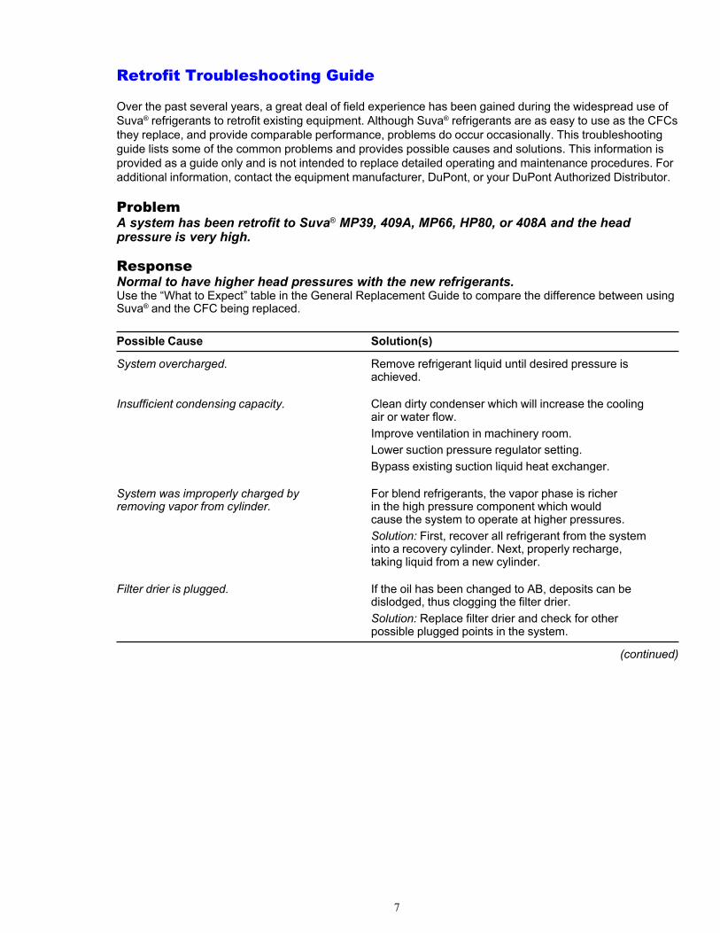
ProblemA system has been retrofit to Suva® MP39, 409A, MP66, HP80, or 408A and the headpressure is very high.
ResponseNormal to have higher head pressures with the new refrigerants.Use the “What to Expect” table in the General Replacement Guide to compare the difference between usingSuva® and the CFC being replaced.
Possible Cause Solution(s)
System overcharged. Remove refrigerant liquid until desired pressure isachieved.
Insufficient condensing capacity. Clean dirty condenser which will increase the coolingair or water flow.Improve ventilation in machinery room.Lower suction pressure regulator setting.Bypass existing suction liquid heat exchanger.
System was improperly charged by For blend refrigerants, the vapor phase is richerremoving vapor from cylinder. in the high pressure component which would
cause the system to operate at higher pressures.Solution: First, recover all refrigerant from the systeminto a recovery cylinder. Next, properly recharge,taking liquid from a new cylinder.
Filter drier is plugged. If the oil has been changed to AB, deposits can bedislodged, thus clogging the filter drier.Solution: Replace filter drier and check for otherpossible plugged points in the system.
(continued)
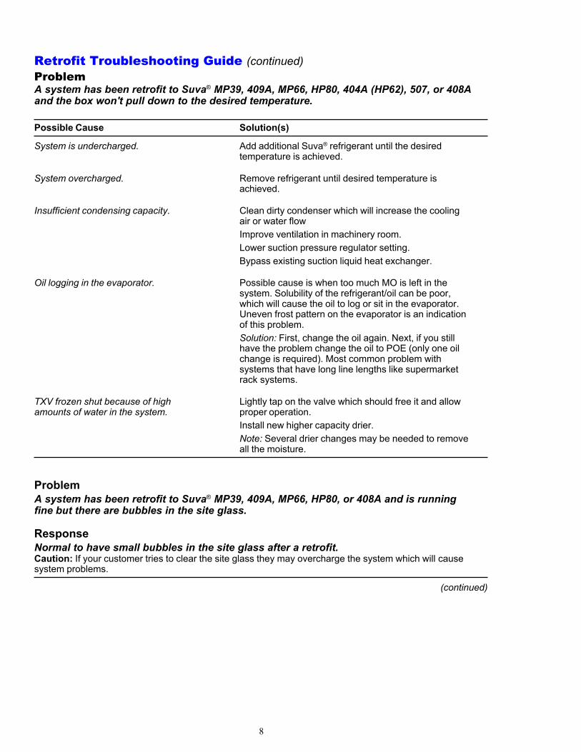
Retrofit Troubleshooting Guide (continued)ProblemA system has been retrofit to Suva® MP39, 409A, MP66, HP80, 404A (HP62), 507, or 408Aand the box won't pull down to the desired temperature.
Possible Cause Solution(s)
System is undercharged. Add additional Suva® refrigerant until the desiredtemperature is achieved.
System overcharged. Remove refrigerant until desired temperature isachieved.
Insufficient condensing capacity. Clean dirty condenser which will increase the coolingair or water flowImprove ventilation in machinery room.Lower suction pressure regulator setting.Bypass existing suction liquid heat exchanger.
Oil logging in the evaporator. Possible cause is when too much MO is left in thesystem. Solubility of the refrigerant/oil can be poor,which will cause the oil to log or sit in the evaporator.Uneven frost pattern on the evaporator is an indicationof this problem.Solution: First, change the oil again. Next, if you stillhave the problem change the oil to POE (only one oilchange is required). Most common problem withsystems that have long line lengths like supermarketrack systems.
TXV frozen shut because of high Lightly tap on the valve which should free it and allowamounts of water in the system. proper operation.
Install new higher capacity drier.Note: Several drier changes may be needed to removeall the moisture.
ProblemA system has been retrofit to Suva® MP39, 409A, MP66, HP80, or 408A and is runningfine but there are bubbles in the site glass.
ResponseNormal to have small bubbles in the site glass after a retrofit.Caution: If your customer tries to clear the site glass they may overcharge the system which will causesystem problems.
(continued)
8
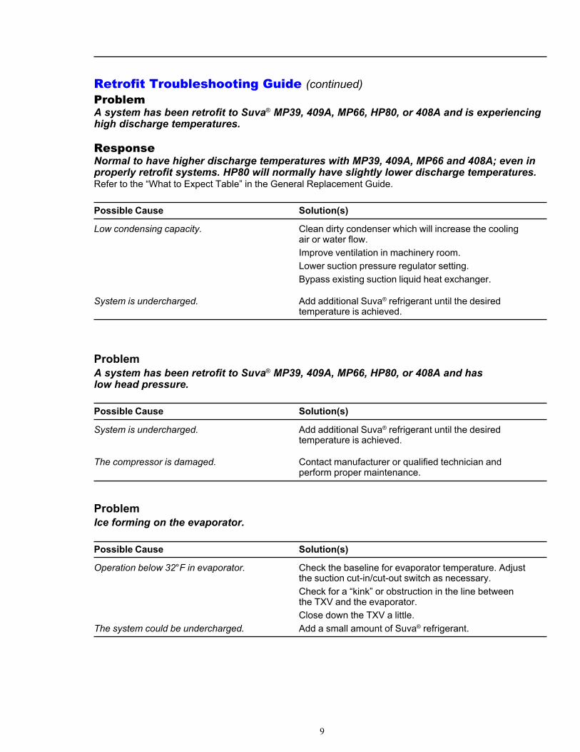
Retrofit Troubleshooting Guide (continued)ProblemA system has been retrofit to Suva® MP39, 409A, MP66, HP80, or 408A and is experiencinghigh discharge temperatures.
ResponseNormal to have higher discharge temperatures with MP39, 409A, MP66 and 408A; even inproperly retrofit systems. HP80 will normally have slightly lower discharge temperatures.Refer to the “What to Expect Table” in the General Replacement Guide.
Possible Cause Solution(s)
Low condensing capacity. Clean dirty condenser which will increase the coolingair or water flow.Improve ventilation in machinery room.Lower suction pressure regulator setting.Bypass existing suction liquid heat exchanger.
System is undercharged. Add additional Suva® refrigerant until the desiredtemperature is achieved.
ProblemA system has been retrofit to Suva® MP39, 409A, MP66, HP80, or 408A and haslow head pressure.
Possible Cause Solution(s)
System is undercharged. Add additional Suva® refrigerant until the desiredtemperature is achieved.
The compressor is damaged. Contact manufacturer or qualified technician andperform proper maintenance.
ProblemIce forming on the evaporator.
Possible Cause Solution(s)
Operation below 32°F in evaporator. Check the baseline for evaporator temperature. Adjustthe suction cut-in/cut-out switch as necessary.Check for a “kink” or obstruction in the line betweenthe TXV and the evaporator.Close down the TXV a little.
The system could be undercharged. Add a small amount of Suva® refrigerant.
9

Pressure/TemperatureRelationshipsTemperature glideOver the past several years, products such as Suva®
MP39 and HP80 have been used to retrofit millionsof direct expansion systems. In these systems,temperature glide has not been a problem. How-ever, in systems with a centrifugal compressor orwith a flooded evaporator, careful design evalua-tion of the system should be performed beforecharging a refrigerant mixture, as the compositiondifference associated with the temperature glidemay impact performance. In general, Suva® MP 39,MP66, 409A and Suva® 407C are not recommendedin these applications.This section is intended to provide you with a morein-depth understanding of temperature glide.During the boiling process for a refrigerant, thetemperature at which a liquid refrigerant firstbegins to boil is known as the saturated liquidtemperature (also called the bubble point tempera-ture). The temperature at which the last drop ofliquid refrigerant has boiled is known as thesaturated vapor temperature (also called the dewpoint temperature). In the condensing process for arefrigerant, the saturated vapor temperature (dewpoint) is the temperature at which the refrigerantvapor first begins to condense; the saturated liquidtemperature (bubble point) is the temperature atwhich all of the refrigerant has been condensed toliquid. At constant pressure, the difference betweenthe saturated vapor temperature and the saturatedliquid temperature is referred to as the “temperatureglide” of the refrigerant.At a given pressure, single component refrigerants,such as CFC-12 and HFC-134a, boil or condense ata constant temperature, i.e., the saturated liquidtemperature and saturated vapor temperature are thesame. As a result, the “temperature glide” of asingle component refrigerant is zero.Refrigerant mixtures behave somewhat differentlythan single component refrigerants when theyboil or condense. In the two phase regions of thesystem, such as the evaporator or condenser, liquidand vapor exist in equilibrium. For a refrigerantmixture at a given temperature or pressure, thecompositions of the liquid and vapor phases aredifferent, with the vapor composition having ahigher concentration of the low boiling pointcomponents in the mixture. As a result of thiscomposition difference, refrigerant mixtures havemeasurable “temperature glide” when they boil
or condense. As shown below, these “effectivetemperature glides” are small for the Suva®
refrigerants:• MP39 and MP66 8°F (4.4°C)• 409A 12°F (6.7°C)• HP80 and HP81 2°F (1.1°C)• 408A 1°F (0.6°C)• 404A (HP62) <1°F (<0.6°C)• 507 <1°F (<0.6°C)• 407C 9°F (5°C)• 410A <1°F (<0.6°C)• 95 <1°F (<0.6°C)
In direct expansion systems using positive displace-ment compressors, the small “temperature glides”of the Suva® blends should result in no significantdifference in heat transfer performance versussingle component refrigerants.In the single phase regions of a refrigeration system(superheated vapor and subcooled liquid), thecomposition of a refrigerant mixture is constantand it behaves exactly like a single componentrefrigerant. Azeotropic refrigerant mixtures, suchas R-500 and R-502, behave like single componentrefrigerants when they are at or very near theirdefined azeotropic point. By definition, the compo-sitions of the vapor phase and liquid phase are thesame for an azeotropic refrigerant mixture at itsazeotropic temperature or pressure.One common misconception about azeotropes,however, is that this behavior holds true every-where in the refrigeration system. These refrigerantmixtures are, in fact, zeotropic mixtures at temper-atures other than their particular azeotropic tem-perature and, at these conditions, will also havedifferent liquid and vapor phase compositions inthe two phase region of a refrigeration system. Asa result of this composition difference, azeotropicrefrigerant mixtures will also have “temperatureglide” at temperatures other than the definedazeotropic point. For R-500 (azeotrope point at32°F [0°C]) and R-502 (azeotrope point at 66°F[18°C]), temperature glides away from the azeo-trope point are very small, typically less than0.3°F (0.2°C).
Temperature glide in an evaporatorIn the boiling process for a given compositionrefrigerant mixture, the liquid phase starts to boilat its saturated liquid temperature (bubble point).While the liquid continues to boil, the liquidphase becomes richer in the high boiling point
10
components as the low boiling point componentsboil off into the vapor phase. Because the liquidcomposition is continually changing during theboiling process, the saturated liquid temperaturealso changes. As the liquid phase becomes richer inthe high boiling point components, the saturatedliquid temperature increases until eventually all ofthe liquid is boiled off, and the saturated vaportemperature is reached. The saturated vapor compo-sition at the exit of the evaporator is the same as thesaturated liquid composition when boiling startedat the expansion device.
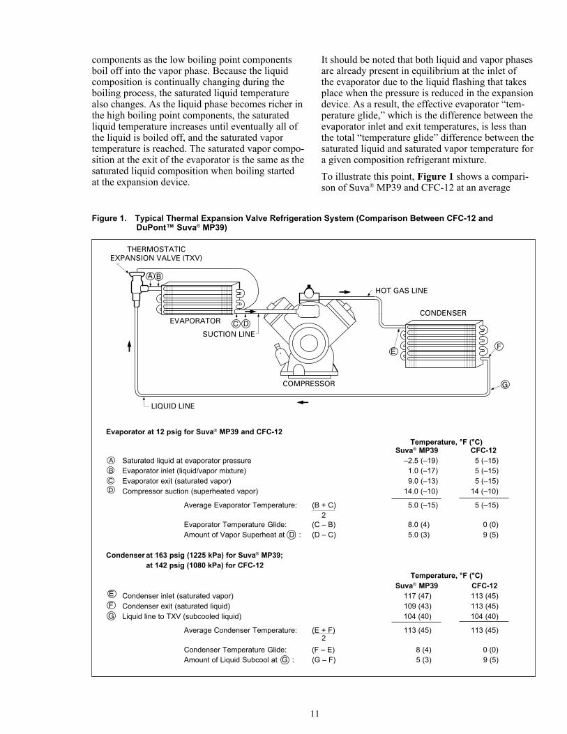
It should be noted that both liquid and vapor phasesare already present in equilibrium at the inlet ofthe evaporator due to the liquid flashing that takesplace when the pressure is reduced in the expansiondevice. As a result, the effective evaporator “tem-perature glide,” which is the difference between theevaporator inlet and exit temperatures, is less thanthe total “temperature glide” difference between thesaturated liquid and saturated vapor temperature fora given composition refrigerant mixture.To illustrate this point, Figure 1 shows a compari-son of Suva® MP39 and CFC-12 at an average
Figure 1. Typical Thermal Expansion Valve Refrigeration System (Comparison Between CFC-12 andDuPont™ Suva® MP39)
THERMOSTATICEXPANSION VALVE (TXV)
EVAPORATOR
BA
COMPRESSOR
LIQUID LINE
SUCTION LINE
HOT GAS LINE
E
G
CONDENSERC
F
D
A
B
C
D
E
F
G
Evaporator at 12 psig for Suva® MP39 and CFC-12Temperature, °F (°C)
Suva® MP39 CFC-12Saturated liquid at evaporator pressure –2.5 (–19) 5 (–15)Evaporator inlet (liquid/vapor mixture) 1.0 (–17) 5 (–15)Evaporator exit (saturated vapor) 9.0 (–13) 5 (–15)Compressor suction (superheated vapor) 14.0 (–10) 14 (–10)
Average Evaporator Temperature: (B + C) 5.0 (–15) 5 (–15)
Evaporator Temperature Glide: (C – B) 8.0 (4) 0 (0)Amount of Vapor Superheat at D : (D – C) 5.0 (3) 9 (5)
Condenser at 163 psig (1225 kPa) for Suva® MP39;at 142 psig (1080 kPa) for CFC-12
Temperature, °F (°C)Suva® MP39 CFC-12
Condenser inlet (saturated vapor) 117 (47) 113 (45)Condenser exit (saturated liquid) 109 (43) 113 (45)Liquid line to TXV (subcooled liquid) 104 (40) 104 (40)
Average Condenser Temperature: (E + F) 113 (45) 113 (45)
Condenser Temperature Glide: (F – E) 8 (4) 0 (0)Amount of Liquid Subcool at G : (G – F) 5 (3) 9 (5)
2
2
11
evaporator temperature of 5°F (–15°C). Subcooledliquid from the condenser (point G) enters thethermostatic expansion valve (TXV) at 104°F(40°C). As the pressure is let down in the TXV,Suva® MP39 first begins boiling when the pressureis reduced to the saturated liquid pressure at 104°F(40°C) and enters the evaporator (point B) as amixture of vapor and liquid at 1°F (–17°C). Forreference, the saturated liquid temperature forSuva® MP39 at the evaporator pressure (point A)is –2.5°F (–19°C). Suva® MP39 continues boilingin the evaporator and exits the evaporator (point C)as a saturated vapor at 9°F (–13°C). Although thetotal “temperature glide” (point C minus point A)is 11.5°F (6.4°C), the effective evaporator “tem-perature glide” (point C minus point B) is only 8°F(4.4°C) or about 70% of the total “temperatureglide.” By comparison, CFC-12 enters the evapora-tor at 5°F (–15°C) and remains at that temperatureuntil boiling is complete.
Superheat calculationFor both Suva® MP39 and CFC-12, the amount ofvapor superheat at a point in the suction line to thecompressor (point D) is calculated from the satu-rated vapor temperature (point C). In this example,the amount of superheat is calculated by subtractingpoint C from point D. For R-12, the superheat is9°F (5°C); for MP39 it is 5°F (2.8°C).In the condensation process for a given composi-tion refrigerant mixture, the vapor phase starts tocondense at its saturated vapor temperature (dewpoint). While the vapor continues to condense, thevapor phase becomes richer in the low boiling pointcomponents as the high boiling point componentscondense into the liquid phase. Because the vaporcomposition is continually changing during thecondensation process, the saturated vapor tempera-ture also changes. As the vapor phase becomesricher in the low boiling point components, thesaturated vapor temperature decreases until eventu-ally all of the vapor is condensed, and the saturatedliquid temperature is reached. The saturated liquidcomposition at the exit of the condenser is the sameas the saturated vapor composition when condensa-tion started at the inlet of the condenser. Therefore,in the condenser, the difference between thestarting saturated vapor temperature and the endingsaturated liquid temperature for a given composi-tion refrigerant mixture is the total “temperatureglide” for that refrigerant mixture.Figure 1 shows a comparison of Suva® MP39 andCFC-12 at an average condenser temperature of113°F (45°C). Suva® MP39 enters the condenser
(point E) as a saturated vapor at 117°F (47°C) andexits the condenser (point F) as a saturated liquidat 109°F (43°C) for a “temperature glide” of 8°F(4.4°C). By comparison, CFC-12 begins condens-ing at 113°F (45°C) and remains at that temperatureuntil condensation is complete.
Subcool calculationFor both Suva® MP39 and CFC-12, the amount ofliquid subcool at a point in the liquid line to theTXV (point G) is calculated from the saturatedliquid temperature (point F). In this example theamount of subcool is calculated by subtractingpoint F from point G. For R-12 the subcool is 9°F(5°C); for MP39 it is 5°F (2.8°C).
Average evaporator and con-denser temperature calculationWhen comparing the performance of zeotropic orazeotropic refrigerant mixtures with that of singlecomponent refrigerants, it is important that thecomparison be made at the average evaporatortemperature and the average condenser tempera-ture. The average evaporator temperature is theaverage of the evaporator inlet and the evaporatorsaturated vapor temperature (usually the evaporatorexit temperature). The average condenser tempera-ture is the average of the condenser inlet tempera-ture (saturated vapor) and the condenser saturatedliquid temperature (usually the condenser exittemperature). In a refrigeration system, the evapo-rator saturated vapor temperature is determinedat the suction pressure of the compressor; thecondenser saturated vapor temperature and thecondenser saturated liquid temperature are deter-mined at the discharge pressure of the compressor.
Suva® MP39, Suva® 409A, Suva® MP66and Suva® 407CFor the typical application ranges for Suva® MP39,409A, MP66, and 407C, both the evaporator andcondenser temperature glides are approximately8°F (4.4°C). The average evaporator temperaturecan be calculated by subtracting 4°F (2.2°C) fromthe saturated vapor temperature. The averagecondenser temperature can be calculated by averag-ing the saturated vapor temperature and saturatedliquid temperature. In field service, where apressure-temperature chart may contain only thesaturated vapor or the saturated liquid temperature,the average condenser temperature can be moreeasily calculated by either subtracting 4°F (2.2°C)from the saturated vapor temperature or adding 4°F(2.2°C) to the saturated liquid temperature.
12

Note: For 409A, the evaporator and condenserglide is slightly higher at 12°F (6.7°C). The samemethods can be used to calculate the averagetemperatures. However, you should use 6°F (3.3°C)when performing the calculation.Note: The amount of vapor superheat is alwayscalculated from the actual saturated vapor tempera-ture; the amount of liquid subcool is always calcu-lated from the actual saturated liquid temperature.Example: Suva® MP39 operating at an evaporatorpressure of 12 psig and a condenser pressure of 163psig (same conditions as shown in Figure 1).Saturated VaporTemperature at 12 psig = 9°F (13°C)Saturated VaporTemperature at 163 psig = 117°F (47°C)Saturated LiquidTemperature at 163 psig = 109°F (43°C)Average EvaporatorTemperature: 9°F – 4°F = 5°F (–15°C)Average Condenser Temperature:117°F – 4°F = 113°F (45°C)or 109°F + 4°F = 113°F (45°C)or (117°F + 109°F)/2 = 113°F (45°C)
Suva® HP80, HP81, and 408AFor the typical application ranges for Suva® HP80,HP81, and 408A, the evaporator temperature glideand the condenser temperature glide are approxi-mately 2°F (1°C). The average evaporator tempera-ture can be calculated by subtracting 1°F (0.6°C)from the saturated vapor temperature. The averagecondenser temperature can be calculated by averag-ing the saturated vapor temperature and saturatedliquid temperature. In field service, where apressure-temperature chart may contain only thesaturated vapor or the saturated liquid temperature,the average condenser temperature can be moreeasily calculated by either subtracting 1°F (0.6°C)from the saturated vapor temperature or adding 1°F(0.6°C) to the saturated liquid temperature.Note: The amount of vapor superheat is alwayscalculated from the actual saturated vapor tempera-ture; the amount of liquid subcool is always calcu-lated from the actual saturated liquid temperature.Example: Suva® HP80 operating at an evaporatorpressure of 15 psig and a condenser pressure of301 psig.Saturated VaporTemperature at 15 psig = –24.3°F (–31°C)
Saturated VaporTemperature at 301 psig = 114°F (46°C)Saturated LiquidTemperature at 301 psig = 112°F (44°C)Average Evaporator Temperature:–24.3°F – 1°F = –25.3°F (–32°C)Average Condenser Temperature:114°F – 1°F = 113°F (45°C)or 112°F + 1°F = 113°F (45°C)or (114°F + 112°F)/2 = 113°F (45°C)
Suva® 404A (HP62), 507, and 410AFor the typical application ranges for Suva® 404A(HP62), 507, and 410A, the evaporator temperatureglide and the condenser temperature glide are verysmall, less than 1°F (0.6°C) for all three refriger-ants. For field service purposes, this glide can beneglected in calculating the average evaporator oraverage condenser temperatures. The evaporatortemperature can be considered equal to the satu-rated vapor temperature at the compressor suctionpressure; the condenser temperature can be consid-ered equal to the saturated vapor temperature or thesaturated liquid temperature at the compressordischarge pressure.Note: The amount of vapor superheat is alwayscalculated from the actual saturated vapor tempera-ture; the amount of liquid subcool is always calcu-lated from the actual saturated liquid temperature.
Expansion DevicesOne consideration when retrofitting a refrigerationor air conditioning system to Suva® refrigerants iswhether the thermostatic expansion valve (TXV) isproperly set for operation with the replacementrefrigerant. Several years of field experienceindicates that the vast majority of systems performwell with the existing TXV. In some cases, theTXV may be improperly set and will need to beadjusted. Occasionally the TXV can't be adjusted toprovide the required capacity and will need to bereplaced. This occurs in a small percentage of thesystems. The following guidelines are provided toassist the user in evaluating the performance of aTXV in systems retrofitted with Suva® refrigerants.Consult the TXV manufacturer for specific recom-mendations for TXV adjustment/replacement.
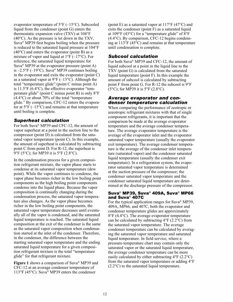
TXV operationTo understand this concept more thoroughly,a review of TXV operation is helpful. A TXVaccomplishes two main functions. First, it throttleshigh pressure (condenser side) to low pressure
13
(evaporator side). Second, it controls the flow rateof refrigerant entering the evaporator so that theevaporator tubes are filled with the proper amountof liquid. As the cooling load on the system in-creases, the valve opens more to increase the flowof refrigerant. Similarly, when the cooling loadon the system decreases, the TXV closes more toreduce the flow of refrigerant. Figure 2 shows theconstruction of a typical TXV. To simplify thisdiscussion, we will assume that there is no pressuredrop in the evaporator, that the force of the up-stream pressure on the valve plug is negligible,and that the TXV’s thermostatic element issystem charged with either saturated R-12 orR-502, depending on the system type.During operation, three forces act to modulate thevalve:P1 = the vapor pressure of the refrigerant charge
in the thermostatic element, which is appliedto the top of the diaphragm and acts to openthe valve.
P2 = the evaporator pressure, which is applied tothe bottom of the diaphragm and acts toclose the valve.
P3 = the pressure exerted by the superheat spring,which is applied to the bottom of the dia-phragm and acts to close the valve. This canchange only if the spring tension is adjusted.
The forces above and below the diaphragm mustbe equal for stable TXV operation:
P1 = P2 + P3For a system at a constant evaporator pressure (P2),if the temperature in the remote bulb increases, sodoes the vapor pressure in the bulb and the pressureon the top of the diaphragm (P1). This will act to“open” the valve since P1 has increased, but P2and P3 have not. If the temperature in the remotebulb decreases, P1 decreases. This acts to “close”the valve since P1 has decreased, but P2 and P3have not.Figure 3 shows the configuration of a TXV/evaporator system. Liquid refrigerant enters theTXV and is reduced in temperature and pressure. Itthen enters the evaporator where it begins to absorbheat and boil. As the refrigerant flows through theevaporator, it continues to boil until all of the liquidhas evaporated. After this occurs (still at the samepressure), the refrigerant vapor continues to flowthrough the evaporator and absorb heat, whichmakes the vapor superheated. The amount ofsuperheat is defined as the number of degrees thatthe gas temperature is above its saturated vaportemperature, at a given pressure. The TXV controlsthe amount of superheat, ensuring that no liquidrefrigerant reaches the compressor. The amount ofsuperheat setpoint is determined by the superheatspring setting.
Figure 2. Typical Thermostatic Expansion Valve
14

Example 1 (see Figure 3)For R-12 operating at an evaporator pressure (P2)of 24.7 psia (170 kPa), the temperature of theliquid-containing portion of the evaporator is at itssaturated vapor temperature, 1.6°F (–16.9°C). If theTXV’s superheat spring is set to give a pressure(P3) of 3 psia (21 kPa), then thermostatic elementpressure (P1) must be 27.7 psia (191 kPa). This isnecessary because the forces on the top and bottomof the diaphragm must be equal for proper TXVoperation. If the remote bulb is charged withsaturated R-12, then it must sense an evaporatorexit temperature of 7.2°F (–13.8°C) to achievethe necessary thermostatic element pressure (P1).This means that the system refrigerant exitingthe evaporator must also be superheated to 7.2°F(–13.8°C). The amount of refrigerant superheat isthe difference between this superheated vaportemperature and the saturated vapor temperature. Inthis case, it would be 5.6°F (3.1°C). This is alsoreferred to as the “degrees of superheat.”
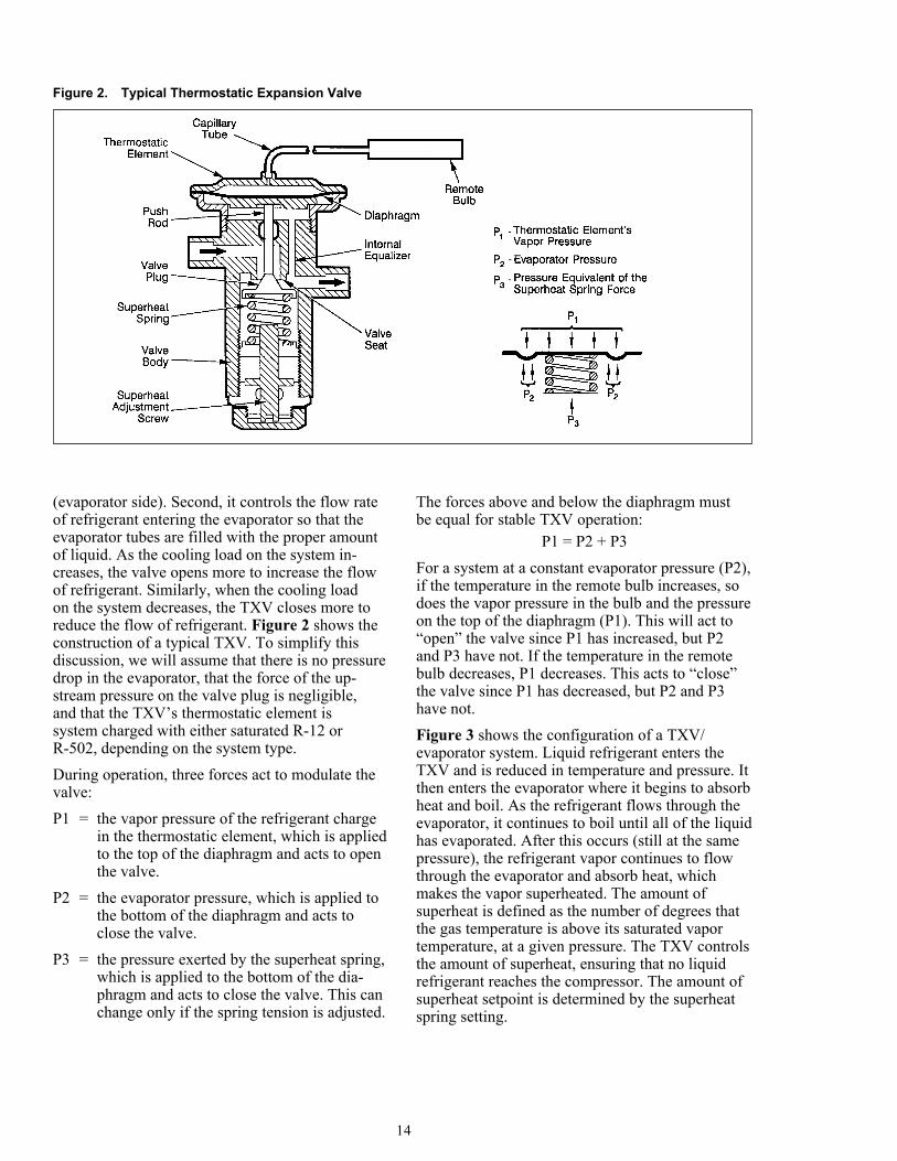
Constant pressure expansion valvesIt is very important to note that in additionto TXVs, constant pressure expansion valves(CPXVs) are used in some applications. Although
these valves may look somewhat like TXVs, theyoperate differently. Figure 4 shows a schematic ofa typical CPXV. Similar to a TXV, three forces acton the diaphragm to modulate the valve. These arethe opening spring force (F1), the force exerted bythe evaporator pressure (F2), and the closing springforce (F3). The opening spring force is adjustableand the closing spring force is not.During constant operation, the forces on the topand the bottom of the diaphragm must be equal:
F1 = F2 + F3The refrigerant flowrate and evaporator pressureare fixed once a constant operating condition exists.Increasing the opening spring force will increasethe refrigerant flowrate and the evaporator pressureand vice versa. This is quite different than a TXV.By increasing a TXV’s superheat spring force, youincrease the amount of superheat and decrease therefrigerant flowrate. Therefore, making the sameadjustment (a clockwise rotation on the adjustmentscrew for instance) has the opposite effect on aTXV than it does on a CPXV. For this reason,it is very important to understand the differencebetween a TXV and a CPXV. In general, CPXVscannot respond to system upsets as well as TXVscan, and therefore are most effective on systemsthat have a constant heat load.
Figure 3. Typical TXV/Evaporator System Operating with R-12
15
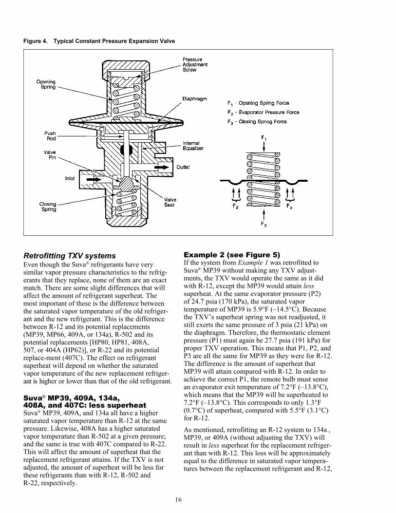
Figure 4. Typical Constant Pressure Expansion Valve
Retrofitting TXV systemsEven though the Suva® refrigerants have verysimilar vapor pressure characteristics to the refrig-erants that they replace, none of them are an exactmatch. There are some slight differences that willaffect the amount of refrigerant superheat. Themost important of these is the difference betweenthe saturated vapor temperature of the old refriger-ant and the new refrigerant. This is the differencebetween R-12 and its potential replacements(MP39, MP66, 409A, or 134a), R-502 and itspotential replacements [HP80, HP81, 408A,507, or 404A (HP62)], or R-22 and its potentialreplace-ment (407C). The effect on refrigerantsuperheat will depend on whether the saturatedvapor temperature of the new replacement refriger-ant is higher or lower than that of the old refrigerant.
Suva® MP39, 409A, 134a,408A, and 407C: less superheatSuva® MP39, 409A, and 134a all have a highersaturated vapor temperature than R-12 at the samepressure. Likewise, 408A has a higher saturatedvapor temperature than R-502 at a given pressure;and the same is true with 407C compared to R-22.This will affect the amount of superheat that thereplacement refrigerant attains. If the TXV is notadjusted, the amount of superheat will be less forthese refrigerants than with R-12, R-502 andR-22, respectively.
Example 2 (see Figure 5)If the system from Example 1 was retrofitted toSuva® MP39 without making any TXV adjust-ments, the TXV would operate the same as it didwith R-12, except the MP39 would attain lesssuperheat. At the same evaporator pressure (P2)of 24.7 psia (170 kPa), the saturated vaportemperature of MP39 is 5.9°F (–14.5°C). Becausethe TXV’s superheat spring was not readjusted, itstill exerts the same pressure of 3 psia (21 kPa) onthe diaphragm. Therefore, the thermostatic elementpressure (P1) must again be 27.7 psia (191 kPa) forproper TXV operation. This means that P1, P2, andP3 are all the same for MP39 as they were for R-12.The difference is the amount of superheat thatMP39 will attain compared with R-12. In order toachieve the correct P1, the remote bulb must sensean evaporator exit temperature of 7.2°F (–13.8°C),which means that the MP39 will be superheated to7.2°F (–13.8°C). This corresponds to only 1.3°F(0.7°C) of superheat, compared with 5.5°F (3.1°C)for R-12.As mentioned, retrofitting an R-12 system to 134a ,MP39, or 409A (without adjusting the TXV) willresult in less superheat for the replacement refriger-ant than with R-12. This loss will be approximatelyequal to the difference in saturated vapor tempera-tures between the replacement refrigerant and R-12,
16
for a given evaporator pressure. The same will betrue for a retrofit from R-22 to 407C, as well as aretrofit from R-502 to 408A.
Example 3An R-12 system operating at an evaporator pressureof 54.7 psia (377 kPa) is retrofitted to 134a withoutmaking any TXV adjustments. From the P–Tcharts, the saturated vapor temperatures of 134aand R-12 are 44.9°F (7.2°C) and 43.3°F (6.3°C),respectively. Subtracting these two numbers gives:
44.9°F (7.2°C) – 43.3°F (6.3°C) = 1.6°F (0.9°C)Therefore, the 134a will be superheated 1.6°F(0.9°C) less than the R-12.If the calculated loss of superheat is greater than theactual amount of superheat, the TXV will notperform properly. For example, if the amount ofsuperheat for R-12 in Example 3 is only 1°F(0.6°C), then the 134a cannot become superheatedif the TXV is not adjusted. Because the TXVcannot force the refrigerant to become superheated,liquid refrigerant can potentially reach the compres-sor, damaging the compressor. TXVs for moststationary refrigeration systems are typically set toprovide at least 10°F (5.6°C) of superheat, which issufficient to accommodate the smaller superheatsexpected with Suva® MP39, 409A, and 134a. SomeTXVs may need to be adjusted to optimize perfor-mance, but TXV replacement is seldom required.
Suva® HP80, 404A (HP62), and 507:more refrigerant superheatSuva® HP80, 404A (HP62), and 507 have lowersaturated vapor temperatures than R-502 (at thesame pressure) in the evaporator pressure range.This results in the opposite effect on refrigerantsuperheat as previously seen with 134a and MP39.When anR-502 system is retrofitted to HP80, 404A (HP62),or 507 without a TXV adjustment, the amount ofsuperheat is higher than with R-502.
Example 4 (see Figures 6 and 7)For R-502 operating at an evaporator pressure (P2)of 24.7 psia (170 kPa), the saturated vapor tempera-ture is –28.7°F (–33.7°C). If the TXV’s superheatspring is set to give a pressure (P3) of 6 psia(41 kPa), then the thermostatic element pressure(P1) must be 30.7 psia (211 kPa). If the remotebulb is charged with saturated R-502, then it mustsense an evaporator exit temperature of –19.0°F(–28.3°C) to achieve the necessary P1. This meansthat the refrigerant vapor must be superheated to–19.0°F (–28.3°C). Because the amount of refriger-ant superheat is the difference between the super-heated vapor and the saturated vapor temperatures,it corresponds to 9.7°F (5.4°C) for this example.
Figure 5. Typical TXV/Evaporator System Operating with Suva® MP39
17
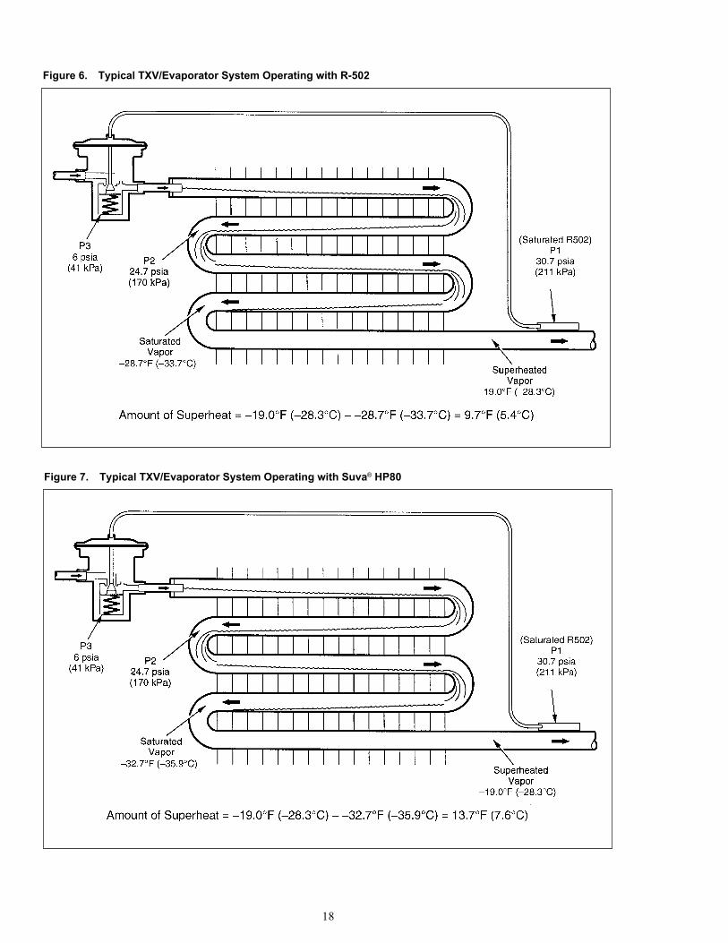
Figure 6. Typical TXV/Evaporator System Operating with R-502
Figure 7. Typical TXV/Evaporator System Operating with Suva® HP80
18
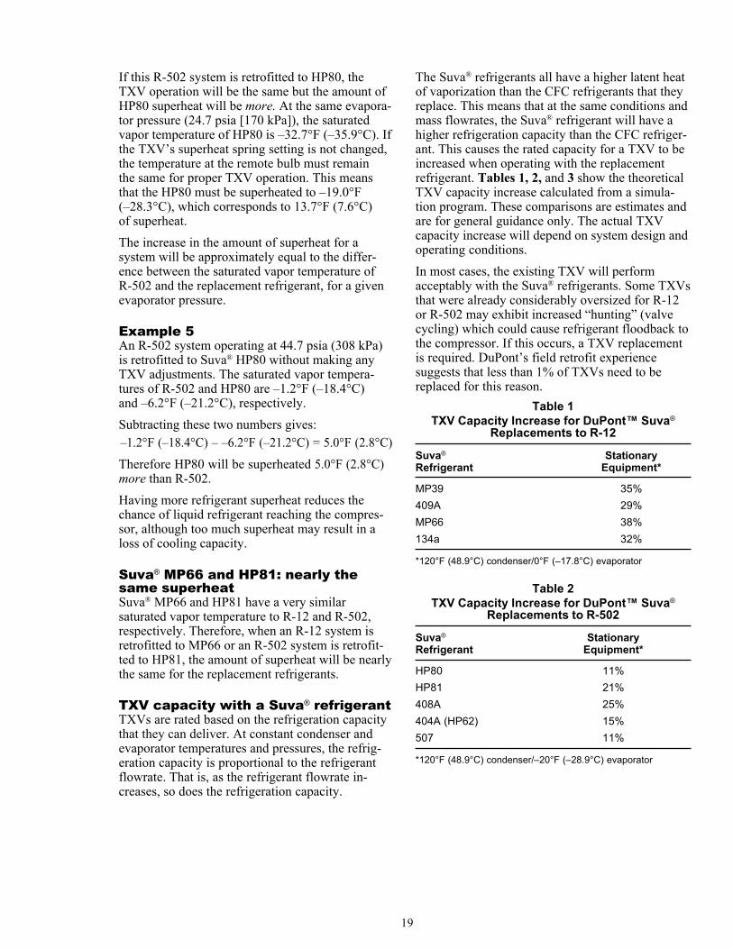
If this R-502 system is retrofitted to HP80, theTXV operation will be the same but the amount ofHP80 superheat will be more. At the same evapora-tor pressure (24.7 psia [170 kPa]), the saturatedvapor temperature of HP80 is –32.7°F (–35.9°C). Ifthe TXV’s superheat spring setting is not changed,the temperature at the remote bulb must remainthe same for proper TXV operation. This meansthat the HP80 must be superheated to –19.0°F(–28.3°C), which corresponds to 13.7°F (7.6°C)of superheat.The increase in the amount of superheat for asystem will be approximately equal to the differ-ence between the saturated vapor temperature ofR-502 and the replacement refrigerant, for a givenevaporator pressure.
Example 5An R-502 system operating at 44.7 psia (308 kPa)is retrofitted to Suva® HP80 without making anyTXV adjustments. The saturated vapor tempera-tures of R-502 and HP80 are –1.2°F (–18.4°C)and –6.2°F (–21.2°C), respectively.Subtracting these two numbers gives:–1.2°F (–18.4°C) – –6.2°F (–21.2°C) = 5.0°F (2.8°C)Therefore HP80 will be superheated 5.0°F (2.8°C)more than R-502.Having more refrigerant superheat reduces thechance of liquid refrigerant reaching the compres-sor, although too much superheat may result in aloss of cooling capacity.
Suva® MP66 and HP81: nearly thesame superheatSuva® MP66 and HP81 have a very similarsaturated vapor temperature to R-12 and R-502,respectively. Therefore, when an R-12 system isretrofitted to MP66 or an R-502 system is retrofit-ted to HP81, the amount of superheat will be nearlythe same for the replacement refrigerants.
TXV capacity with a Suva® refrigerantTXVs are rated based on the refrigeration capacitythat they can deliver. At constant condenser andevaporator temperatures and pressures, the refrig-eration capacity is proportional to the refrigerantflowrate. That is, as the refrigerant flowrate in-creases, so does the refrigeration capacity.
The Suva® refrigerants all have a higher latent heatof vaporization than the CFC refrigerants that theyreplace. This means that at the same conditions andmass flowrates, the Suva® refrigerant will have ahigher refrigeration capacity than the CFC refriger-ant. This causes the rated capacity for a TXV to beincreased when operating with the replacementrefrigerant. Tables 1, 2, and 3 show the theoreticalTXV capacity increase calculated from a simula-tion program. These comparisons are estimates andare for general guidance only. The actual TXVcapacity increase will depend on system design andoperating conditions.In most cases, the existing TXV will performacceptably with the Suva® refrigerants. Some TXVsthat were already considerably oversized for R-12or R-502 may exhibit increased “hunting” (valvecycling) which could cause refrigerant floodback tothe compressor. If this occurs, a TXV replacementis required. DuPont’s field retrofit experiencesuggests that less than 1% of TXVs need to bereplaced for this reason.
Table 1TXV Capacity Increase for DuPont™ Suva®
Replacements to R-12
Suva® StationaryRefrigerant Equipment*
MP39 35%409A 29%MP66 38%134a 32%
*120°F (48.9°C) condenser/0°F (–17.8°C) evaporator
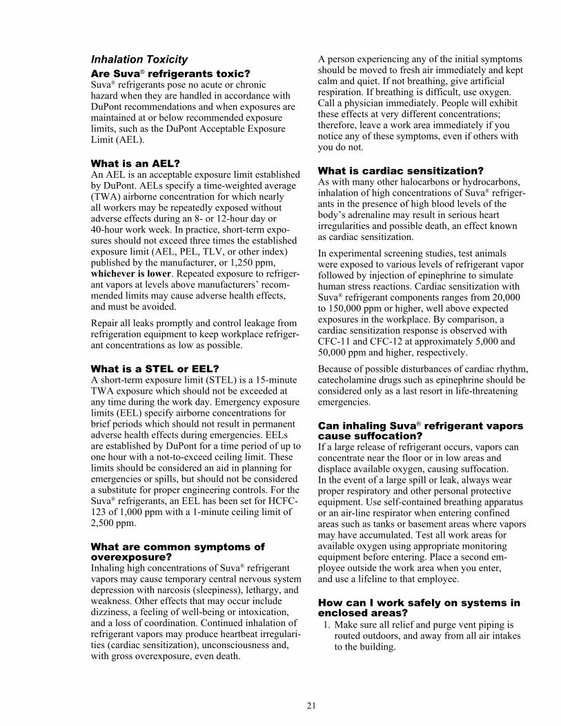
Table 2TXV Capacity Increase for DuPont™ Suva®
Replacements to R-502
Suva® StationaryRefrigerant Equipment*
HP80 11%HP81 21%408A 25%404A (HP62) 15%507 11%
*120°F (48.9°C) condenser/–20°F (–28.9°C) evaporator
19
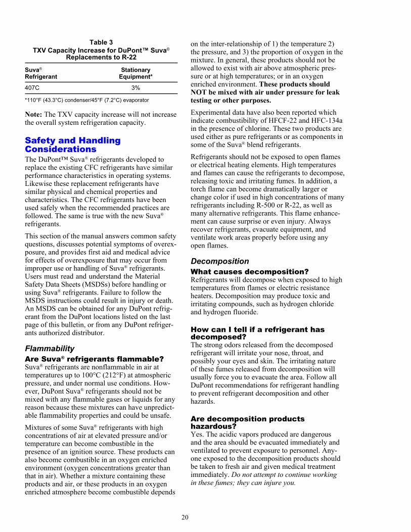
Table 3TXV Capacity Increase for DuPont™ Suva®
Replacements to R-22
Suva® StationaryRefrigerant Equipment*
407C 3%
*110°F (43.3°C) condenser/45°F (7.2°C) evaporator
Note: The TXV capacity increase will not increasethe overall system refrigeration capacity.
Safety and HandlingConsiderationsThe DuPont™ Suva® refrigerants developed toreplace the existing CFC refrigerants have similarperformance characteristics in operating systems.Likewise these replacement refrigerants havesimilar physical and chemical properties andcharacteristics. The CFC refrigerants have beenused safely when the recommended practices arefollowed. The same is true with the new Suva®
refrigerants.This section of the manual answers common safetyquestions, discusses potential symptoms of overex-posure, and provides first aid and medical advicefor effects of overexposure that may occur fromimproper use or handling of Suva® refrigerants.Users must read and understand the MaterialSafety Data Sheets (MSDSs) before handling orusing Suva® refrigerants. Failure to follow theMSDS instructions could result in injury or death.An MSDS can be obtained for any DuPont refrig-erant from the DuPont locations listed on the lastpage of this bulletin, or from any DuPont refriger-ants authorized distributor.
FlammabilityAre Suva® refrigerants flammable?Suva® refrigerants are nonflammable in air attemperatures up to 100°C (212°F) at atmosphericpressure, and under normal use conditions. How-ever, DuPont Suva® refrigerants should not bemixed with any flammable gases or liquids for anyreason because these mixtures can have unpredict-able flammability properties and could be unsafe.Mixtures of some Suva® refrigerants with highconcentrations of air at elevated pressure and/ortemperature can become combustible in thepresence of an ignition source. These products canalso become combustible in an oxygen enrichedenvironment (oxygen concentrations greater thanthat in air). Whether a mixture containing theseproducts and air, or these products in an oxygenenriched atmosphere become combustible depends
on the inter-relationship of 1) the temperature 2)the pressure, and 3) the proportion of oxygen in themixture. In general, these products should not beallowed to exist with air above atmospheric pres-sure or at high temperatures; or in an oxygenenriched environment. These products shouldNOT be mixed with air under pressure for leaktesting or other purposes.Experimental data have also been reported whichindicate combustibility of HFCF-22 and HFC-134ain the presence of chlorine. These two products areused either as pure refrigerants or as components insome of the Suva® blend refrigerants.Refrigerants should not be exposed to open flamesor electrical heating elements. High temperaturesand flames can cause the refrigerants to decompose,releasing toxic and irritating fumes. In addition, atorch flame can become dramatically larger orchange color if used in high concentrations of manyrefrigerants including R-500 or R-22, as well asmany alternative refrigerants. This flame enhance-ment can cause surprise or even injury. Alwaysrecover refrigerants, evacuate equipment, andventilate work areas properly before using anyopen flames.
DecompositionWhat causes decomposition?Refrigerants will decompose when exposed to hightemperatures from flames or electric resistanceheaters. Decomposition may produce toxic andirritating compounds, such as hydrogen chlorideand hydrogen fluoride.
How can I tell if a refrigerant hasdecomposed?The strong odors released from the decomposedrefrigerant will irritate your nose, throat, andpossibly your eyes and skin. The irritating natureof these fumes released from decomposition willusually force you to evacuate the area. Follow allDuPont recommendations for refrigerant handlingto prevent refrigerant decomposition and otherhazards.
Are decomposition productshazardous?Yes. The acidic vapors produced are dangerousand the area should be evacuated immediately andventilated to prevent exposure to personnel. Any-one exposed to the decomposition products shouldbe taken to fresh air and given medical treatmentimmediately. Do not attempt to continue workingin these fumes; they can injure you.
20
Inhalation ToxicityAre Suva® refrigerants toxic?Suva® refrigerants pose no acute or chronichazard when they are handled in accordance withDuPont recommendations and when exposures aremaintained at or below recommended exposurelimits, such as the DuPont Acceptable ExposureLimit (AEL).
What is an AEL?An AEL is an acceptable exposure limit establishedby DuPont. AELs specify a time-weighted average(TWA) airborne concentration for which nearlyall workers may be repeatedly exposed withoutadverse effects during an 8- or 12-hour day or40-hour work week. In practice, short-term expo-sures should not exceed three times the establishedexposure limit (AEL, PEL, TLV, or other index)published by the manufacturer, or 1,250 ppm,whichever is lower. Repeated exposure to refriger-ant vapors at levels above manufacturers’ recom-mended limits may cause adverse health effects,and must be avoided.Repair all leaks promptly and control leakage fromrefrigeration equipment to keep workplace refriger-ant concentrations as low as possible.
What is a STEL or EEL?A short-term exposure limit (STEL) is a 15-minuteTWA exposure which should not be exceeded atany time during the work day. Emergency exposurelimits (EEL) specify airborne concentrations forbrief periods which should not result in permanentadverse health effects during emergencies. EELsare established by DuPont for a time period of up toone hour with a not-to-exceed ceiling limit. Theselimits should be considered an aid in planning foremergencies or spills, but should not be considereda substitute for proper engineering controls. For theSuva® refrigerants, an EEL has been set for HCFC-123 of 1,000 ppm with a 1-minute ceiling limit of2,500 ppm.
What are common symptoms ofoverexposure?Inhaling high concentrations of Suva® refrigerantvapors may cause temporary central nervous systemdepression with narcosis (sleepiness), lethargy, andweakness. Other effects that may occur includedizziness, a feeling of well-being or intoxication,and a loss of coordination. Continued inhalation ofrefrigerant vapors may produce heartbeat irregulari-ties (cardiac sensitization), unconsciousness and,with gross overexposure, even death.
A person experiencing any of the initial symptomsshould be moved to fresh air immediately and keptcalm and quiet. If not breathing, give artificialrespiration. If breathing is difficult, use oxygen.Call a physician immediately. People will exhibitthese effects at very different concentrations;therefore, leave a work area immediately if younotice any of these symptoms, even if others withyou do not.
What is cardiac sensitization?As with many other halocarbons or hydrocarbons,inhalation of high concentrations of Suva® refriger-ants in the presence of high blood levels of thebody’s adrenaline may result in serious heartirregularities and possible death, an effect knownas cardiac sensitization.In experimental screening studies, test animalswere exposed to various levels of refrigerant vaporfollowed by injection of epinephrine to simulatehuman stress reactions. Cardiac sensitization withSuva® refrigerant components ranges from 20,000to 150,000 ppm or higher, well above expectedexposures in the workplace. By comparison, acardiac sensitization response is observed withCFC-11 and CFC-12 at approximately 5,000 and50,000 ppm and higher, respectively.Because of possible disturbances of cardiac rhythm,catecholamine drugs such as epinephrine should beconsidered only as a last resort in life-threateningemergencies.
Can inhaling Suva® refrigerant vaporscause suffocation?If a large release of refrigerant occurs, vapors canconcentrate near the floor or in low areas anddisplace available oxygen, causing suffocation.In the event of a large spill or leak, always wearproper respiratory and other personal protectiveequipment. Use self-contained breathing apparatusor an air-line respirator when entering confinedareas such as tanks or basement areas where vaporsmay have accumulated. Test all work areas foravailable oxygen using appropriate monitoringequipment before entering. Place a second em-ployee outside the work area when you enter,and use a lifeline to that employee.
How can I work safely on systems inenclosed areas?
1. Make sure all relief and purge vent piping isrouted outdoors, and away from all air intakesto the building.
21
2. Make certain the area is well ventilated. Useauxiliary ventilation such as blowers or fans,if necessary, to disperse refrigerant vapors.
3. Test the work area for available oxygen beforeentering enclosed areas. Do not use a leakmonitor to test for oxygen. A refrigerant leakdetector will not tell you if adequate oxygen ispresent to sustain life.
4. Install refrigerant leakage detection and oxygenmonitoring equipment in the work areas. For adiscussion of leak detection equipment, seeDuPont technical bulletin ARTD-27A. Also,refer to ASHRAE Standard 15-1994, “SafetyCode for Mechanical Ventilation,” for ventila-tion and air monitoring requirements forequipment rooms.
What should I do if a largerefrigerant leak or spill occurs?Do not attempt to enter the area to repairequipment until the vapors are dispersed, oruntil you are equipped with proper breathingapparatus. Evacuate everyone until the area hasbeen ventilated. Use blowers or fans to circulate airat the floor level and in any basement or low areas.
Is the deliberate inhalation of Suva®
refrigerant dangerous?Intentional misuse or deliberate inhalation of Suva®
refrigerants may cause death without warning.This practice is extremely dangerous.
Can I smell Suva® refrigerants?Most refrigerants have such a faint odor that theycan be difficult to detect even at dangerous levels.Do not use smell as a test for safe levels of refriger-ants in a work area. Frequent leak checks and airmonitoring are the only adequate ways to determinethat areas are safe for entry and work.
Mechanical equipment roomrequirements• Install an air monitor capable of detecting the
refrigerant(s) used in concentrations up to theEEL or STEL.
• Install suitable alarms that activate at or belowthe refrigerant’s AEL, and that will alert personsoutside of the equipment room that a leak condi-tion exists.
• Route relief valve discharge headers and purgeunits outdoors, away from all air intakes tobuilding.
• Install local exhaust to ventilate the work areain the event that the air monitor alarm point isexceeded.
• Follow minimum standards for refrigerants asrequired and specified by ASHRAE Standard15–1994.
Refer to DuPont technical bulletin AS-5 for moredetailed guidelines for using HCFC-123 in refrig-eration and air-conditioning applications.
Skin and eye contactIs skin or eye contact with Suva®
refrigerants hazardous?At room temperature, Suva® refrigerant vaporshave little effect on skin or eyes.Always wear protective clothing, including long-sleeved clothing and gloves, when there is a risk ofexposure to liquid refrigerants. Protection shouldinclude goggles and face shield to protect the eyes.If liquid refrigerant enters your eyes, flush themwith plenty or water, then seek medical attention.
Is frostbite a possible hazard?In liquid form, Suva® refrigerants can freeze skinor eyes on contact, causing frostbite. If you aresplashed with liquid, immediately remove allclothing that contains refrigerant to preventadditional freezing. Soak the exposed area inlukewarm water, not cold or hot. Do not usedressings or ointments. Then seek medical atten-tion immediately.
Pressure and cylinder safetyCan pressurized refrigerants evercause a hazard?Yes. Some of the potential hazards may include:• An overfilled container, vessel, or pipeline where
temperature increases may cause a “liquid full”situation and immediately create a dangerousincrease in hydrostatic pressure, which can causehigh-pressure leaks or even rupture of the vessel.
• A correctly filled returnable or disposablecylinder that is heated above the recommendedmaximum temperature of 125°F (52°C) couldresult in dangerously high pressures, possiblyin excess of the cylinder design pressure.
• A returnable or disposable refrigerant cylinderconnected to the discharge side of refrigerationor air-conditioning equipment may be exposedto pressures that can exceed the capacity of thecylinder relief devices, causing the cylinder torupture or shatter.
22
DuPont owns returnable refrigerant cylinders andton tanks. No returnable container may be refilledby a user without DuPont consent. United StatesDepartment of Transportation regulations forbidtransportation of returnable cylinders refilledwithout DuPont authorization.
What are the proper proceduresfor safely handling disposable andreturnable cylinders?• Remove liquid from the cylinder when charging
any Suva® blend. Once removed from the cylin-der it can be flashed to vapor for charging.
• Verify proper hookup of charging hoses. Do notcharge to the discharge side of the compressor.
• Open valves slowly.• Protect cylinders from moisture and rusting
during storage.• Verify that the refrigerant label matches any
color code or labeling used on the equipment.• Do not tamper with any relief devices on cylin-
ders or refrigerant equipment.• Do not drop, dent, or mechanically abuse
containers.• Do not recharge disposable or refillable cylinders
with used refrigerants.• Do not use disposable cylinders as compressed
air tanks.• Do not force connections.• Do not use flame on cylinders to heat them.
Never expose cylinders to temperatures above125°F (52°C).
How should I correctly braze orweld piping on refrigeration orair-conditioning equipment?• Make certain there is adequate ventilation in the
work area, and that you have tested the air spacefor safe levels of refrigerant vapor and oxygen.
• Evacuate the Suva® refrigerant from the equip-ment you will be repairing. Recover the refriger-ant into a proper recovery cylinder. Do not ventrefrigerant.
• Purge system with nitrogen if available. If not,open the system and ensure no residual pressureis present. Drain all lubricant possible from thearea to be welded to prevent fires.
• Leave system open during repair to preventpressure buildup.
• Use auxiliary ventilation to disperse any fumes ordecomposing refrigerant that may have remainedin the piping or equipment during the repairprocess.
• If you notice an increase in the size or shape ofthe open flame, or the flame changes color, stopwork immediately and reventilate the equipment.This flame enhancement effect should be awarning that too much refrigerant vapor is stillpresent around the equipment.
General precautions for handlingSuva® refrigerants• Never pressurize systems or vessels containing
Suva® refrigerants with air for leak testing or anyother purpose.
• Never heat cylinders above 125°F (52°C). Do notplace cylinders near flames or heat sources, ordiscard into fires.
• Never use torches or open flames to heat cylin-ders during refrigerant charging operations.
• Never tamper with valves or pressure reliefdevices.
• Never refill disposable cylinders with anything.Any refrigerant heels should be used or trans-ferred to recovery containers, and the emptycylinder should be properly disposed of.
• Never refill disposable or returnable cylinderswith reclaimed refrigerants or lubricants. Useonly proper recovery cylinders for this purpose. Itis illegal to ship original cylinders with usedrefrigerants.
• Never use disposable refrigerant cylinders ascompressed air tanks. Refrigerant cylinders arenot coated properly on the inside, and moisturefrom compressed air will cause corrosion. Thiscan weaken the cylinder and cause a violentrupture. There may be NO evidence of cylinderweakening until it fails.
• Always store refrigerant cylinders in a dry area.Storage in damp areas may permit corrosion,which will weaken the cylinders over time. Alsodo not store in direct sunlight where cylindertemperatures can exceed 125°F (52°C).
• Never mix refrigerants in a system.
Recovery, Reclamation, andRecycleResponsible useResponsible use of Suva® refrigerants requiresthat the product be recovered for reuse or disposalwhenever possible. DuPont purchases used refrig-erants for reclamation through its distributornetworks in the United States, Canada, andEurope. In the United States, used Suva® refriger-ants are accepted as part of this program. Recovery
23
and reuse of Suva® refrigerants makes sense froman environmental and economic standpoint. Inaddition, the U.S. Clean Air Act prohibits knownventing of CFC, HCFC, and HFC refrigerantsduring the maintenance, servicing, or disposal ofrefrigeration equipment.
RecoveryRecovery refers to the removal of refrigerants fromequipment and collection in an approved recoverycontainer. As defined by the Air Conditioning andRefrigeration Institute (ARI), a U.S. organization,recovery does not involve processing or analyticaltesting. Refrigerants may be recovered fromrefrigeration equipment using permanent on-siteequipment or one of the portable recovery devicesnow on the market. The portable devices contain asmall compressor and an air cooled condenser andmay be used for vapor or liquid recovery. At theend of the recovery cycle, the system is evacuatedto remove vapors. In the United States, the Environ-mental Protection Agency (EPA) sets standards forrecovery equipment. Before purchasing a specificrecovery unit, check with the manufacturer to besure that it contains elastomeric seals and a com-pressor oil compatible with refrigerants.
ReclamationReclamation refers to the reprocessing of usedrefrigerants to ARI 700 specifications. Quality ofreclaimed product is verified by chemical analysis.Contact DuPont or one of its Authorized Distribu-tors for further information. Reclamation offers
24
advantages over on-site refrigerant recyclingprocedures, because these systems cannot guaranteecomplete removal of contaminants. Putting refriger-ants that do not meet new product specificationsback into expensive equipment may cause damage.
RecycleRefrigerant recycle refers to the reduction of usedrefrigerant contaminants using devices that reduceoil, water, acidity, and particulates. Recycle isusually a field or shop procedure with no analyticaltesting of refrigerant. Refrigerants may be recycledusing many of the devices now available, providingthat the entire charge is removed from the refrigera-tion equipment and recycled. If you routinelyrecycle refrigerants through several cycles, werecommend that you have the composition of therefrigerant checked periodically. This will preventloss of performance, in the unlikely event that thecomposition has shifted.In the United States, the EPA sets standardsfor recycle equipment. Consult with the manufac-turer before specifying a recycle device for anyrefrigerant.
DisposalDisposal refers to the destruction of used refriger-ants. Disposal may be necessary when refrigerantshave become badly contaminated with otherproducts and no longer meet the acceptance specifi-cations of DuPont or other reclaimers. Be sure tocheck the qualifications of any firm before sendingthem used refrigerants.


(4/05) 300204A Printed in U.S.A.[Replaces: H-77939-4]Reorder No.: H-77939-5
JapanMitsui DuPont Fluorochemicals
Co., Ltd.Chiyoda Honsha Bldg.5-18, 1-Chome SarugakuchoChiyoda-Ku, Tokyo 101-0064 Japan81-3-5281-5805
AsiaDuPont TaiwanP.O. Box 81-777Taipei, Taiwan886-2-514-4400
DuPont China LimitedP.O. Box TST 988511122 New World Office Bldg.(East Wing)Tsim Sha TsuiKowloon, Hong KongPhone: 852-734-5398Fax: 852-236-83516
DuPont Thailand Ltd.9-11 Floor, Yada Bldg.56 Silom RoadSuriyawongse, BankrakBangkok 10500Phone: 66-2-238-0026Fax: 66-2-238-4396
DuPont China Ltd.Rm. 1704, Union Bldg.100 Yenan Rd. EastShanghai, PR China 200 002Phone: 86-21-328-3738Telex: 33448 DCLSH CNFax: 86-21-320-2304
EuropeDuPont de NemoursInternational S.A.2 Chemin du PavillonP.O. Box 50CH-1218 Le Grand-SaconnexGeneva, Switzerland41-22-717-5111
CanadaDuPont Canada, Inc.P.O. Box 2200, StreetsvilleMississauga, Ontario
CanadaL5M 2H3(905) 821-3300
MexicoDuPont, S.A. de C.V.Homero 206Col. Chapultepec MoralesC.P. 11570 Mexico, D.F.52-5-722-1100
South AmericaDuPont do Brasil S.A.Alameda Itapecuru, 506Alphaville 06454-080 BarueriSão Paulo, Brazil55-11-7266-8263
DuPont Argentina S.A.Casilla Correo 1888Correo Central1000 Buenos Aires, Argentina54-1-311-8167
PacificDuPont AustraliaP.O. Box 930North Sydney, NSW 2060Australia61-2-99236111
DuPont Far East Inc.6th Floor Bangunan SamudraNo. 1 JLN. Kontraktor U1/14, SEK U1Hicom-Glenmarie Industrial Park40150 Shah Alam, Selangor MalaysiaPhone 60-3-517-2534
DuPont Korea Inc.4/5th Floor, Asia Tower#726, Yeoksam-dong, Kangnam-kuSeoul, 135-082, Korea82-2-721-5114
DuPont Singapore Pte. Ltd.1 Maritime Square #07 01World Trade CentreSingapore 040965-273-2244
DuPont Far East, Philippines8th Floor, Solid Bank Bldg.777 Paseo de RoxasMakati, Metro ManilaPhilippinesPhone: 63-2-818-9911Fax: 63-2-818-9659
DuPont Far East Inc.7A Murray’s Gate RoadAlwarpetMadras, 600 018, India91-44-454-029
DuPont Far East Inc.—Pakistan9 Khayaban-E-ShaheenDefence Phase 5Karachi, Pakistan 92-21-533-350
DuPont Far East Inc.P.O. Box 2553/JktJakarta 10001, Indonesia62-21-517-800
The information contained herein is based on technical data and tests which we believe to be reliable and is intended for use by persons having technicalskill, at their own discretion and risk. Because conditions of use are outside of DuPont control, we can assume no liability for results obtained or damagesincurred through the application of the data presented.
For Further Information:DuPont FluorochemicalsWilmington, DE 19880-0711(800) 235-SUVAwww.suva.dupont.com
Copyright © 2005 DuPont or its affiliates. All rights reserved. The DuPont Oval Logo, DuPont™, The miracles of science™ and Suva® areregistered trademarks or trademarks of DuPont or its affiliates.
NO PART OF THIS MATERIAL MAY BE REPRODUCED, STORED IN A RETRIEVAL SYSTEM OR TRANSMITTED IN ANY FORM ORBY ANY MEANS ELECTRONIC, MECHANICAL, PHOTOCOPYING, RECORDING OR OTHERWISE WITHOUT THE PRIOR WRITTENPERMISSION OF DUPONT.