drive system application - automatización industrial ... · drive system application ... ¾...
TRANSCRIPT

Drive System Application
SIMATIC / MICROMASTER 4
Application Description
Function block to operate MICROMASTER 4 on Profibus DP

Table of Contents
Function block to operate MICROMASTER 4 on Profibus DP SIMATICMICROMASTER 4
A&D SD Page 2/25
Cop
yrig
ht ©
Sie
men
s A
G 2
005
All
right
s re
serv
ed
Table of Contents
1 Warranty, liability and support ...................................................................... 4
2 Description ...................................................................................................... 5
2.1 Use of the application .................................................................................... 5
2.2 Block functions............................................................................................... 6
2.3 Limitations/constraints .................................................................................. 7 2.3.1 Can be used for MICROMASTER from ............................................................ 7 2.3.2 Can be used for MICROMASTER with............................................................. 7 2.3.3 Cannot be used for ........................................................................................... 7 2.3.4 Restrictions: ...................................................................................................... 7 2.3.5 Software prerequisites ...................................................................................... 7
3 Installing the example .................................................................................... 8
3.1 MM4 connected to S7 and OP without Drive ES Basic and without Starter8
3.2 MM4 connected to S7 and OP with Drive ES Basic and with Starter......... 9
4 Function description .................................................................................... 10
4.1 Control and feedback signals...................................................................... 10
4.2 Controlling the drive..................................................................................... 11 4.2.1 Starting the drive:............................................................................................ 11 4.2.2 Stopping the drive:.......................................................................................... 12
4.3 Automatic commissioning........................................................................... 12 4.3.1 Tasks that are to be handled using this function ............................................ 12 4.3.2 Adapting the parameter DBs .......................................................................... 13 4.3.3 Entering parameters into the DB .................................................................... 14 4.3.4 Automatically commissioning the drive........................................................... 15 4.3.5 Motor identification routine and saturation characteristic................................ 16
4.4 Parameter transfer........................................................................................ 16
4.5 Diagnostics ................................................................................................... 19 4.5.2 Faults/disturbances and warnings/alarms of the MM4.................................... 21 4.5.3 Parameter transfer error and automatic commissioning................................. 21
4.6 Version data of Micromaster ....................................................................... 22
4.7 Adapting the program .................................................................................. 22
4.8 Called sub-programs.................................................................................... 22
5 Error messages............................................................................................. 23

Table of Contents
Function block to operate MICROMASTER 4 on Profibus DP SIMATICMICROMASTER 4
A&D SD Page 3/25
Cop
yrig
ht ©
Sie
men
s A
G 2
005
All
right
s re
serv
ed
5.1 Datenfehler. Nr. ............................................................................................. 23
5.2 Datenfehler. DP_Zusatzinfo ......................................................................... 24
5.3 Datenfehler. Fehler_Inbetriebnahme .......................................................... 24
6 Technical data............................................................................................... 25

Warranty, liability and support
Function block to operate MICROMASTER 4 on Profibus DP SIMATICMICROMASTER 4
A&D SD Page 4/25
Cop
yrig
ht ©
Sie
men
s A
G 2
005
All
right
s re
serv
ed
1 Warranty, liability and support
We do not accept any liability for the information contained in this document.
Claims against us - irrespective of the legal grounds - resulting from the use of the examples, information, programs, engineering and performance data etc., described in this document are excluded. Such an exclusion shall not apply where liability is mandatory e.g. under the German Product Liability Act involving intent, gross negligence, or injury of life, body or health, guarantee for the quality of a product, fraudulent concealment of a deficiency or non-performance. Claims of the purchaser for compensation relating to non-performance of essential contract obligations shall be limited to foreseeable damages typically covered by a contract unless intent, willful misconduct or gross negligence is involved or injury of life, body or health. The above stipulations shall not change the burden of proof to your detriment.
The application examples are not binding and do not claim to be complete regarding the circuits shown and equipping as well as possible eventualities. They do not represent customer-specific solutions. They are only intended to provide support for typical applications. You are responsible in ensuring that the described products are correctly used. These application examples do not relieve you of the responsibility in safely and professionally using, installing, operating and servicing equipment. When using these application examples, you recognize that Siemens cannot be made liable for any damage/claims beyond the liability clause described above. We reserve the right to make changes to this application example at any time without prior notice. If there are any deviations between the recommendations provided in this application example and other Siemens publications - e.g. Catalogs - then the contents of the other documents have priority.
Copyright© 2005 Siemens A&D. It is not permissible to transfer or copy these application examples or excerpts of them without first having prior authorization from Siemens A&D in writing.
If you have any questions relating to this document then please send them to us at the following e-mail address:
mailto:[email protected]

Description
Function block to operate MICROMASTER 4 on Profibus DP SIMATICMICROMASTER 4
A&D SD Page 5/25
Cop
yrig
ht ©
Sie
men
s A
G 2
005
All
right
s re
serv
ed
2 Description
2.1 Use of the application
This application is used to implement a drive that can be operated with a setpoint that can continually change. A SIMATIC S7 300/400 with a MICROMASTER MM4 is used as basis for this solution. Both the SIMATIC S7 300/400 and MICROMASTER MM4 are coupled through Profibus DP. The following functional areas are handled using this function block.
• The PLC controls (operates) the drive.
• The PLC saves the drive parameters and automatically commissions the drive. A PG/PC is not required for series commissioning (when several drive systems are commissioned).
• If a Micromaster is replaced, the PLC automatically commissions the new Micromaster. Neither special know-how nor PC with parameterizing software is required.
• Diagnostic functions are displayed:
Error with error values Old errors with old error values Alarms Old alarms Profibus errors Block errors Micromaster version
• Any parameter can be read and written to (at the OP, parameters can only
be read)
• The software can be simply adapted to specific requirements.

Description
Function block to operate MICROMASTER 4 on Profibus DP SIMATICMICROMASTER 4
A&D SD Page 6/25
Cop
yrig
ht ©
Sie
men
s A
G 2
005
All
right
s re
serv
ed
Profibus DP
MPI
2.2 Block functions
• The drive is started and stopped. • The setpoint is cyclically entered as percentage value [ -100 to +100]. • Fast stop with its own ramp-down time. • Drive faults and alarms are automatically displayed and the DP error
evaluated. • The Micromaster type, the version and the firmware version are displayed • The configured parameters are saved in a motor DB • “Quick commissioning” and then additional parameters are transferred • Motor data is identified with parameter change • Saturation characteristic is identified with parameter change • User interface that can be used to read or write any parameter • A minimum of CPU programming is required when implementing the
operator interface on the OP.

Description
Function block to operate MICROMASTER 4 on Profibus DP SIMATICMICROMASTER 4
A&D SD Page 7/25
Cop
yrig
ht ©
Sie
men
s A
G 2
005
All
right
s re
serv
ed
2.3 Limitations/constraints
2.3.1 Can be used for MICROMASTER from
• MM 411 V 1.10 • MM 420 V 1.17 • MM 430 V 2.00 • MM 440 V 2.05
2.3.2 Can be used for MICROMASTER with
• SIMATIC S7 300 from CPU 313-2DP • SIMATIC S7 400 • SIMATIC C7 • SINUMERIK
2.3.3 Cannot be used for
• SIMATIC S7 200 • SIMATIC S5
2.3.4 Restrictions:
• The system does not monitor as to whether the start signal is permissible.
2.3.5 Software prerequisites
• Step 7 V 5.1 SP 6

Installing the example
Function block to operate MICROMASTER 4 on Profibus DP SIMATICMICROMASTER 4
A&D SD Page 8/25
Cop
yrig
ht ©
Sie
men
s A
G 2
005
All
right
s re
serv
ed
3 Installing the example
3.1 MM4 connected to S7 and OP without Drive ES Basic and without Starter
• Set the DP address at the MM4. Additional settings do not have to be made. The MM4 does not have to have the factory settings.
• Start HW Config • Configure the PLC • Configure MICROMASTER 4
In the PROFIBUS-DP/SIMOVERT Catalog, select MICROMASTER 4. 1. Select the bus in the working sheet 2. In the Catalog, double click on PROFIBUS-DP/SIMOVERT/MICROMASTER 4 Here, the sub-points are still not selected. The Micromaster 4 directory that might be listed is for Drive ES and is therefore not used in this case.
• Set and accept the Profibus address • The slot allocation for the MM4 is displayed at the bottom left in the
window (the MM4 that is set-up must be selected) • Select slot 1 and under PROFIBUS-DP/SIMOVERT > MICROMASTER 4 select 4 PKW, 2 PZD (PPO1). • “Save and Compile” HW Config and “Download to Module” • Copy the blocks from the program example into the user program. • Copy the symbol table in the user program and adapt. • All of the block numbers can be changed. • Load the program into the PLC and start the PLC. • Call the OP screen form, MM4 diagnostics and if required, remove any
DP errors. • Call the OP screen form – commissioning or VAT commissioning. • Enter motor data into the parameter DB • Start automatic commissioning. (I_Enable = 0; I_Enable_QC = 1; IO_W_Parameters = 1) • After the automatic commissioning has been completed without any
errors, start the motor identification routine. • The motor can now be started using the variable tables.
Installing the example
Function block to operate MICROMASTER 4 on Profibus DP SIMATICMICROMASTER 4
A&D SD Page 9/25
Cop
yrig
ht ©
Sie
men
s A
G 2
005
All
right
s re
serv
ed
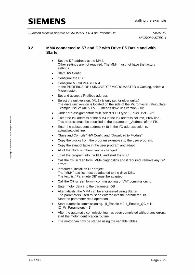
3.2 MM4 connected to S7 and OP with Drive ES Basic and with Starter
• Set the DP address at the MM4. Other settings are not required. The MM4 must not have the factory settings.
• Start HW Config • Configure the PLC • Configure MICROMASTER 4
In the PROFIBUS-DP / SIMOVERT / MICROMASTER 4 Catalog, select a Micromaster.
• Set and accept a Profibus address • Select the unit version. (V1.1x is only set for older units.)
The drive unit version is located on the side of the Micromaster rating plate: Example: Issue: A01/2.05 means drive unit version 2.0x
• Under pre-assignment/default, select “PPO type 1, PKW+PZD-2/2”. • Enter the I/O address of the MM4 in the I/O address column, PKW line.
This address must be specified at the parameter I_Address of the FB. • Enter the subsequent address (+ 8) in the I/O address column,
actual/setpoint line. • “Save and Compile” HW Config and “Download to Module” • Copy the blocks from the program example into the user program. • Copy the symbol table in the user program and adapt. • All of the block numbers can be changed. • Load the program into the PLC and start the PLC. • Call the OP screen form, MM4 diagnostics and if required, remove any DP
errors. • If required, install an OP project.
The “MM4” text list must be adapted to the drive DBs. The text list “ParameterDB” must be adapted.
• Call the OP screen form – commissioning or VAT commissioning. • Enter motor data into the parameter DB • Alternatively, the MM4 can be engineered using Starter.
The parameters used must be entered into the parameter DB. Start the parameter read operation.
• Start automatic commissioning. (I_Enable = 0; I_Enable_QC = 1; IO_W_Parameters = 1)
• After the automatic commissioning has been completed without any errors, start the motor identification routine.
• The motor can now be started using the variable tables.
Function description
Function block to operate MICROMASTER 4 on Profibus DP SIMATICMICROMASTER 4
A&D SD Page 10/25
Cop
yrig
ht ©
Sie
men
s A
G 2
005
All
right
s re
serv
ed
4 Function description
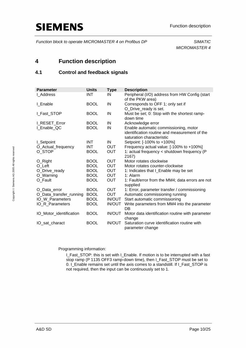
4.1 Control and feedback signals
Parameter Units Type Description I_Address INT IN Peripheral (I/O) address from HW Config (start
of the PKW area) I_Enable BOOL IN Corresponds to OFF 1; only set if
O_Drive_ready is set. I_Fast_STOP BOOL IN Must be set; 0: Stop with the shortest ramp-
down time I_RESET_Error BOOL IN Acknowledge error I_Enable_QC BOOL IN Enable automatic commissioning, motor
identification routine and measurement of the saturation characteristic
I_Setpoint INT IN Setpoint: [-100% to +100%] O_Actual_frequency INT OUT Frequency actual value: [-100% to +100%] O_STOP BOOL OUT 1: actual frequency < shutdown frequency (P
2167) O_Right BOOL OUT Motor rotates clockwise O_Left BOOL OUT Motor rotates counter-clockwise O_Drive_ready BOOL OUT 1: Indicates that I_Enable may be set O_Warning BOOL OUT 1: Alarm O_Fault BOOL OUT 1: Fault/error from the MM4; data errors are not
supplied O_Data_error BOOL OUT 1: Error, parameter transfer / commissioning O_Data_transfer_running BOOL OUT Automatic commissioning running IO_W_Parameters BOOL IN/OUT Start automatic commissioning IO_R_Parameters BOOL IN/OUT Write parameters from MM4 into the parameter
DB IO_Motor_identification BOOL IN/OUT Motor data identification routine with parameter
change IO_sat_charact BOOL IN/OUT Saturation curve identification routine with
parameter change
Programming information:
I_Fast_STOP: this is set with I_Enable. If motion is to be interrupted with a fast stop ramp (P 1135 OFF3 ramp-down time), then I_Fast_STOP must be set to 0. I_Enable remains set until the axis comes to a standstill. If I_Fast_STOP is not required, then the input can be continuously set to 1.

Function description
Function block to operate MICROMASTER 4 on Profibus DP SIMATICMICROMASTER 4
A&D SD Page 11/25
Cop
yrig
ht ©
Sie
men
s A
G 2
005
All
right
s re
serv
ed
4.2 Controlling the drive
4.2.1 Starting the drive:
• Set I_Fast_STOP.
If a fast stop is not required, then I_Fast_STOP can be permanently
assigned a 1.
• O_Drive_ready is output.
The following conditions must be fulfilled:
+ the drive is stationary
+ I_Fast_STOP = 1
+ no fault/error
+ I_Enable = 0
+ a commissioning function is not running
• The speed is entered in I_Setpoint in the range from –100 % to +100 %.
If 0% setpoint is entered with the enable signal switched-in, the drive is
stationary and the motor temperature can inadmissibly rise (temperature
problem).
The setpoint is cyclically transferred to the drive. Changes become
immediately active.
(ramp-up time in P1120; ramp-down time in P1121)
• Set I_Enable. (ramp-up time in P1120)
The drive is only powered-up with a rising edge.
In the user program it must be ensured that a rising edge at I_Enable is
only permitted if O_Drive_ready is output.
• The outputs O_STOP, O_Right and O_Left indicate as to whether the
motor is rotating and in which direction it is rotating.
• The frequency actual value is displayed in O_Actual_frequency. Units: -100
to +100%

Function description
Function block to operate MICROMASTER 4 on Profibus DP SIMATICMICROMASTER 4
A&D SD Page 12/25
Cop
yrig
ht ©
Sie
men
s A
G 2
005
All
right
s re
serv
ed
4.2.2 Stopping the drive:
• Set I_Enable to 0: The drive stops with the ramp-down time in P1121 and
is powered-down.
• Set the setpoint to 0: The drive stops with the ramp-down time in P1121.
The closed-loop control is switched-out; this is the reason that the
temperature must be carefully monitored.
• Set I_Fast_STOP to 0. I_Enable remains at 1 until the drive comes to a
standstill.
Drive stops with the ramp-down time in P1135.
4.3 Automatic commissioning
4.3.1 Tasks that are to be handled using this function
• The function of this software is essentially adequate. An OP is always used at the machine. The Starter software will not be used to provide support when commissioning the drive and when servicing the drive. When service is required, the electrical technician replaces the MM4, the cable or the motor without any commissioning know-how. The automatic commissioning function and when required the motor identification routine are then started at the OP. If an MM420 is defective, an MM440 must be installed as spare part taking into account the changed connection assignment.
• Starter is used when commissioning for the first time.
The parameter DB is adapted when required and the parameters being used are saved (backed-up) in the DB. Service concept: refer above.
• Machines with several identical axes are constructed. The individual axes
are identical in all of the machines. The 1st axis of a type is commissioned using Starter. All of the additional axes are commissioned just the same as when service is required. Service concept: refer above.
Function description
Function block to operate MICROMASTER 4 on Profibus DP SIMATICMICROMASTER 4
A&D SD Page 13/25
Cop
yrig
ht ©
Sie
men
s A
G 2
005
All
right
s re
serv
ed
4.3.2 Adapting the parameter DBs
The parameter DB comprises 2 areas 1 area: Motor data
All of the parameters associated with the fast commissioning function are entered here. The list is already prepared and should be adequate in almost all of the cases. The possible parameters are listed in the parameter descriptions in the Chapter Fast commissioning (P0010=1). Motor data set 0 is used as standard. If several motor data sets are required for a motor, then several parameter DBs must be set-up. The number of the motor data set is then entered in the variable Z_Motor_data_DBNr.
1 area: Technology data
All of the other parameters that are being used are entered here Rules to adapt the parameter DBs All of the parameters used to commission a drive are entered into the list. For the technology parameters, for each parameter, the required sub-parameter number can be entered under the index. The 1st sub-parameter has the index 0. The data [2] in the parameter list signifies that there are sub-parameters 0 and 1. The data type of the value should always be adapted to the appropriate parameter. The length of the list can be modified when required.

Function description
Function block to operate MICROMASTER 4 on Profibus DP SIMATICMICROMASTER 4
A&D SD Page 14/25
Cop
yrig
ht ©
Sie
men
s A
G 2
005
All
right
s re
serv
ed
4.3.3 Entering parameters into the DB
1st version
• Axis was completely commissioned
• I_Enable is set to 0
• I_Enable_QC is set
• When IO_R_Parameters is set, data transfer starts
An error message is not output if the data transfer cannot be started.
• O_Data_transfer_running: 1 while data is being transferred
If commissioning cannot be started, then the bit is not set.
• The IO_R_Parameters is reset after transfer has been completed.
• If an error occurs, transfer is interrupted at the incorrect parameter.
2nd version
• The parameters are entered at the OP.
• However, only those parameters are to be displayed on the OP whose
change makes sense.
• All of the other parameters should be defined using the initial values.
• If there are several drives in a system, then the data structure of the DBs
should be identical.
• It is also permissible to have gaps in the lists. Advantage: Indirect
addressing can be used at the OP.

Function description
Function block to operate MICROMASTER 4 on Profibus DP SIMATICMICROMASTER 4
A&D SD Page 15/25
Cop
yrig
ht ©
Sie
men
s A
G 2
005
All
right
s re
serv
ed
4.3.4 Automatically commissioning the drive
4.3.4.1 Control and feedback signals for data transfer Parameter Type Sort Signal type Description Z_Motor_data_DBNr INT STAT Permanently
assign Enter the number of the parameter DBs
Z_Tech_data_DBNr INT STAT Permanently assign
Permanently set to 0. (only for special applications)
I_Enable BOOL IN Set to 0, otherwise the function is inhibited
I_Enable_QC BOOL IN Set to 1, otherwise the function is inhibited
IO_W_Parameters BOOL IN User sets FB clears
Starts automatic commissioning. FB clears once the function has ended.
O_Data_transfer_running BOOL OUT 1 during commissioning O_Data_fault BOOL STAT Display Error when commissioning the
system I_RESET_Error BOOL IN Pulse Commissioning errors are
acknowledged
Comment: If an error occurs, commissioning is interrupted at the incorrect parameter.
4.3.4.2 Prerequisites
• The correct Profibus address must be set at the MM4. • It is not permissible that the FB outputs a DP error. • Any parameter settings are possible in the MM4.
This also applies to Profibus parameters. • The version of the MM4 must correspond to the above specified data. • Automatic commissioning must be enabled. • The valid version of the MM4 must be located in the instance DB.
I_RESET_Error reads-out the valid version.
4.3.4.3 Automatic commissioning procedure
• Establish (restore) the factory setting • Carry-out the fast (quick) commissioning • Transfer the technology data • Save parameters in the EEPROM

Function description
Function block to operate MICROMASTER 4 on Profibus DP SIMATICMICROMASTER 4
A&D SD Page 16/25
Cop
yrig
ht ©
Sie
men
s A
G 2
005
All
right
s re
serv
ed
4.3.4.4 Starting the control (open-loop)
• If the control (open-loop) is disabled during the automatic commissioning procedure, then after a restart/new start, the automatic commissioning procedure must be interrupted with I_RESET_Error.
4.3.5 Motor identification routine and saturation characteristic
A motor identification routine should always be executed after the automatic commissioning procedure has been completed. If the automatic commissioning procedure was not completed error-free, then it is not permissible to start the motor identification routine. Reason: the function was not ended as the MM4 did not correctly respond. Remedy: interrupt (abort) the motor identification routine with I_RESET_Error and carry-out an automatic commissioning procedure. The motor data identification routine may only be carried-out with the motor in the cold condition as otherwise the drive could oscillate. The saturation characteristic can only be identified for MM440 drive inverters.
4.4 Parameter transfer
Using PKW communications, this application can read and write all of the MM 4 parameters. A parameter is transferred using a read / write request. The first three requests are available for the application.
Several requests can be simultaneously started. The requests are executed one after the other, starting with request 1. Application example: If two requests are to be transferred one after the other in a certain sequence, then they are managed in two requests that immediately follow one another. Both of these requests are started together. A step sequence is not required.
A request can manage an individual parameter or a parameter with several sub-parameters. The following belong to a request:
• 1 request bit to start data transfer • 1 error bit • 1 request data block in which the request is described and the value is
saved There is a common error display for all of the requests

Function description
Function block to operate MICROMASTER 4 on Profibus DP SIMATICMICROMASTER 4
A&D SD Page 17/25
Cop
yrig
ht ©
Sie
men
s A
G 2
005
All
right
s re
serv
ed
4.4.1.1 Structure of request blocks Job_1 to Job_3: Parameter Type Initial value Description Job_1.Parameter_Nr INT 0 Parameter No. from the parameter table Job_1.Index INT 0 No. sub-parameter / for List No. of the last
parameter Job_1.Identifier Byte B#16#0 1/11: read 2/12: write 3/13: write to
EEPROM Job_1.Identifier_internal Byte B#16#0 Is automatically set Job_1.Value_0 DINT L#0 Value to be transferred Job_1.Value_1 DINT L#0 Value to be transferred Job_1.Value_2 DINT L#0 Value to be transferred
Example
Parameter Type Initial value Description Job_1.Parameter_Nr INT 1002 Fixed frequency 2 Job_1.Index INT 0 P 1002 has no sub-parameters Job_1.Identifier Byte B#16#2 2: write Job_1.Identifier_internal Byte B#16#0 Is automatically set Job_1.Value_0 REAL L#0 Value to be transferred Job_1.Value_1 DINT L#0 Not used here Job_1.Value_2 DINT L#0 Not used here
Rules:
• Not all Value_n have to be used. • The texts of the error bits associated with the request bits can be modified. • The texts Job_1 to Job_16 in the request blocks may not be changed. • For requests that are always the same, initial values can be set in the
instance DB.
4.4.1.2 Initializing the request block:
Parameter_Nr.: Parameter No. Index: If an individual parameter is to be transferred print 0 (for Parameter has no sub-parameters) the No. of the sub-parameter If several sub-parameters of a parameter are to be
transferred, print the No. of the last sub-parameter to be transferred.

Function description
Function block to operate MICROMASTER 4 on Profibus DP SIMATICMICROMASTER 4
A&D SD Page 18/25
Cop
yrig
ht ©
Sie
men
s A
G 2
005
All
right
s re
serv
ed
Identifier: 1: Reading an individual parameter 2: Writing an individual parameter into the RAM 3: Writing an individual parameter into the EEPROM 11: Reading several sub-parameters of a parameter 12: Writing several sub-parameters of a parameter into
the RAM 13: Writing several sub-parameters of a parameter into
the EEPROM The IDs do not correspond to the PKW IDs. Identifier_internal: Here, during data transfer, the block automatically enters
the PKW IDs. Value_0 to Value_2: The value is entered that is to be written. When required,
the data type can be adapted.
4.4.1.3 Control signals of the request blocks: Parameter Type Initial value Description Job.RW_Request_1 BOOL False Trigger request 1 (the name can be
modified) Job.RW_Request_2 BOOL False Trigger request 2 (the name can be
modified) Job.RW_Request_3 BOOL False Trigger request 3 (the name can be
modified) Data_fault.Job.RW_Request_1 BOOL False Error request 1 (the name can be
modified) Data_fault.Job.RW_Request_2 BOOL False Error request 2 (the name can be
modified) Data_fault.Job.RW_Request_3 BOOL False Error request 3 (the name can be
modified)

Function description
Function block to operate MICROMASTER 4 on Profibus DP SIMATICMICROMASTER 4
A&D SD Page 19/25
Cop
yrig
ht ©
Sie
men
s A
G 2
005
All
right
s re
serv
ed
4.4.1.4 Behavior of the request bit Job.RW_Request_1/2/3
• The user sets it to start data transfer • The FB resets it if the request was ended with or without error. • Several bits can be simultaneously set. • Bits can be set if other bits are already set. • The requests are executed one after the other starting with
JOB_RW_Request_1. Example:
JOB_RW_Request_4 and JOB_RW_Request_5 are started together. While JOB_RW_Request_4 is being processed, JOB_RW_Request_1 is set. After JOB_RW_Request_4 has been executed, JOB_RW_Request_5 is processed.
• When required, the user can delete the bits. Requests that have already been started are processed to the end. Under certain circumstances, an error message is also generated.
• If a parameter should be continuously read, then the request bit must be cyclically set.
• If a request was ended with an error, then the appropriate error bit is set.
4.5 Diagnostics
There are several error sources. 1. Fault/disturbance and warning/alarms of the MM4 2. Fault messages of the standard FCs used 3. Fault messages of the block 4. Fault messages of the parameter transfer

Function description
Function block to operate MICROMASTER 4 on Profibus DP SIMATICMICROMASTER 4
A&D SD Page 20/25
Cop
yrig
ht ©
Sie
men
s A
G 2
005
All
right
s re
serv
ed
4.5.1.1 Control and feedback signals of the diagnostics Parameter Type Sort Description O_Warning BOOL OUT 1: As long as alarms are present O_Fault BOOL OUT 1: Error from the MM4; data errors are not displayedO_Data_error BOOL OUT 1: Error, parameter transfer / commissioning I_RESET_Error BOOL IN • Acknowledges errors on the MM4
• Deletes all data error displays • Does not interrupt requests to transfer
parameters that are actually running • Interrupts a commissioning procedure that is
running Data errors. JOB_RW_Request_ BOOL STAT For each request to transfer a parameter, one error
bit. Nr INT STAT Error No.
Caution: If Job_Nr <> 0, then a value of 0 is an error.
DP_Add_info HEX STAT Error message from SFC14/15 Job_Nr INT STAT [1..16] indicates the erroneous request Index INT STAT Task index Parameter_Nr INT STAT Parameter No. from the erroneous request Fault_Commissioning INT STAT Error No.
The following displays are only updated if O_Warning or O_Fault are set.
4.5.1.2 Display for faults/disturbances and warnings/alarms
Parameter Type Sort Signal type Description Job_13.Value_0 DINT STAT Display Last alarm; alarm 1 Job_13.Value_1 DINT STAT Display Last alarm; alarm 2 Job_13.Value_2 DINT STAT Display Last alarm - 1; alarm 1 Job_13.Value_3 DINT STAT Display Last alarm - 2; alarm 2 Job_14.Value_0 DINT STAT Display Last fault; fault 1 Job_14.Value_1 DINT STAT Display Last fault; fault 2 Job_14.Value_2 DINT STAT Display Last fault – 1; fault 1 Job_14.Value_3 DINT STAT Display Last fault – 1; fault 2 Job_14.Value_4 DINT STAT Display Last fault – 2; fault 1 Job_14.Value_5 DINT STAT Display Last fault – 2; fault 2 Job_14.Value_6 DINT STAT Display Last fault – 3; fault 1 Job_14.Value_7 DINT STAT Display Last fault – 3; fault 2 Job_14.Value_0 DINT STAT Display Last fault; fault value 1 (service info.) Job_14.Value_1 DINT STAT Display Last fault; fault value 2 (service info.) Job_14.Value_2 DINT STAT Display Last fault – 1; fault value 1 (service info.) Job_14.Value_3 DINT STAT Display Last fault – 1; fault value 2 (service info.) Job_14.Value_4 DINT STAT Display Last fault – 2; fault value 1 (service info.) Job_14.Value_5 DINT STAT Display Last fault – 2; fault value 2 (service info.) Job_14.Value_6 DINT STAT Display Last fault – 3; fault value 1 (service info.) Job_14.Value_7 DINT STAT Display Last fault – 3; fault value 2 (service info.)

Function description
Function block to operate MICROMASTER 4 on Profibus DP SIMATICMICROMASTER 4
A&D SD Page 21/25
Cop
yrig
ht ©
Sie
men
s A
G 2
005
All
right
s re
serv
ed
4.5.2 Faults/disturbances and warnings/alarms of the MM4
As soon as the MM4 signals a fault/disturbance or warning/alarm, the parameters are read-out of the MM4. If the FB detects a DP error, then error 1001 Job_14.Value_0 is displayed. The precise DP error is located in the Data_fault.DP_Add_info. This error corresponds to the error message of the SFC14/15. Under certain circumstances there is an error value for each fault/disturbance. The fault value contains important information for Siemens service.
4.5.3 Parameter transfer error and automatic commissioning
• The FB implements 16 requests to transfer parameters. If neither DP error nor hardware fault occurs, then only error messages from requests 1 to 3 and from requests 4 and 12 can be expected.
• The displays Data_fault.Job. ..... indicate all requests that were aborted
with error. In this case, an error bit with the same name is assigned to each request. In practice, generally, only one error occurs.
• The displays Data_fault.Nr., .Job_Nr., .Index and .Parameter_Nr. indicate
the first error that was identified. • SFC 14/15 outputs error messages in DP_Add_info.
The value is continuously updated as long as there is a DP error. • Data_fault.Fault_Commissioning indicates error messages associated with
the automatic commissioning. If there is an error in the parameter DB, then the following display appears: O_Data_error = 1 Data_fault.Job.RW_Request_12 = 1 Data_fault.Nr = Error description Data_fault.Job_Nr = 12 No. of the sub-parameter or motor data set Data_fault.Parameter_Nr = Parameter No. from the parameter DB Data_fault.Fault_Commissioning = 1002
• If the automatic commissioning was interrupted with error 17 (request was
not able to be executed due to the operating state) in request 4, then this error can be acknowledged and the system re-started.

Function description
Function block to operate MICROMASTER 4 on Profibus DP SIMATICMICROMASTER 4
A&D SD Page 22/25
Cop
yrig
ht ©
Sie
men
s A
G 2
005
All
right
s re
serv
ed
4.6 Version data of Micromaster
The version data are read-out with I_RESET_Error.
Parameter Type Sort Signal type Description Job_16.Value_0 DINT STAT Display 42: Siemens Job_16.Value_1 DINT STAT Display Micromaster type Job_16.Value_2 DINT STAT Display Firmware revision Job_16.Value_3 DINT STAT Display Date: Year Job_16.Value_4 DINT STAT Display Date: Day/month
4.7 Adapting the program
• When required, the user can adapt the control program.
The network “Process parameter request” may not be modified. • When required, the instance data block can also be adapted. All data areas
can be shifted. It is not possible to access absolute addresses. The struct names Job_1 to Job_16 may not be changed as a single entity.
• The name of the request bit and the associated error bit can be adapted.
Example: JOB.RW_Request_1 can be changed to JOB.R_Output_current • PCD_send and PCD_receive can be changed.
4.8 Called sub-programs
The standard FCs SFC 14 (DPRD_DAT) and SFC 15 (DPWR_DAT) are used. If no parameters are transferred, then these blocks are not called.
Error messages
Function block to operate MICROMASTER 4 on Profibus DP SIMATICMICROMASTER 4
A&D SD Page 23/25
Cop
yrig
ht ©
Sie
men
s A
G 2
005
All
right
s re
serv
ed
5 Error messages
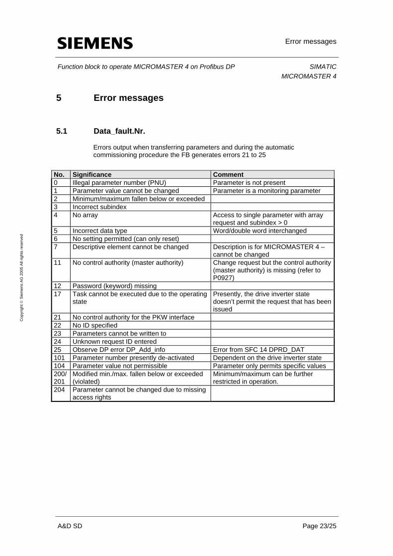
5.1 Data_fault.Nr.
Errors output when transferring parameters and during the automatic commissioning procedure the FB generates errors 21 to 25
No. Significance Comment 0 Illegal parameter number (PNU) Parameter is not present 1 Parameter value cannot be changed Parameter is a monitoring parameter 2 Minimum/maximum fallen below or exceeded 3 Incorrect subindex 4 No array Access to single parameter with array
request and subindex > 0 5 Incorrect data type Word/double word interchanged 6 No setting permitted (can only reset) 7 Descriptive element cannot be changed Description is for MICROMASTER 4 –
cannot be changed 11 No control authority (master authority) Change request but the control authority
(master authority) is missing (refer to P0927)
12 Password (keyword) missing 17 Task cannot be executed due to the operating
state Presently, the drive inverter state doesn’t permit the request that has been issued
21 No control authority for the PKW interface 22 No ID specified 23 Parameters cannot be written to 24 Unknown request ID entered 25 Observe DP error DP_Add_info Error from SFC 14 DPRD_DAT 101 Parameter number presently de-activated Dependent on the drive inverter state 104 Parameter value not permissible Parameter only permits specific values 200/201
Modified min./max. fallen below or exceeded (violated)
Minimum/maximum can be further restricted in operation.
204 Parameter cannot be changed due to missing access rights
Error messages
Function block to operate MICROMASTER 4 on Profibus DP SIMATICMICROMASTER 4
A&D SD Page 24/25
Cop
yrig
ht ©
Sie
men
s A
G 2
005
All
right
s re
serv
ed
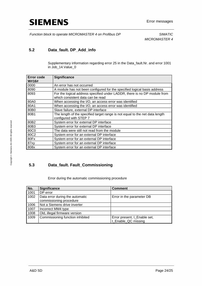
5.2 Data_fault. DP_Add_info
Supplementary information regarding error 25 in the Data_fault.Nr. and error 1001 in Job_14.Value_0
Error code W#16#
Significance
0000 An error has not occurred 8090 A module has not been configured for the specified logical basis address 8093 For the logical address specified under LADDR, there is no DP module from
which consistent data can be read 80A0 When accessing the I/O, an access error was identified 80A1 When accessing the I/O, an access error was identified 80B0 Slave failure, external DP interface 80B1 The length of the specified target range is not equal to the net data length
configured with STEP 7 80B2 System error for external DP interface 80B3 System error for external DP interface 80C0 The data were still not read from the module 80C2 System error for an external DP interface 80Fx System error for an external DP interface 87xy System error for an external DP interface 808x System error for an external DP interface
5.3 Data_fault. Fault_Commissioning
Error during the automatic commissioning procedure
No. Significance Comment 1001 DP error 1002 Data error during the automatic
commissioning procedure Error in the parameter DB
1006 Not a Siemens drive inverter 1007 Incorrect MM4 type 1008 Old, illegal firmware version 1009 Commissioning function inhibited Error present, I_Enable set,
I_Enable_QC missing

Technical data
Function block to operate MICROMASTER 4 on Profibus DP SIMATICMICROMASTER 4
A&D SD Page 25/25
Cop
yrig
ht ©
Sie
men
s A
G 2
005
All
right
s re
serv
ed
6 Technical data
Block: FB Block name: MM4 Version: V 2.2 Language in which it was generated: STL Local data: 36 byte MC 7 code: 3166 byte Load memory requirement: 4244 byte Working memory requirement: 3202 byte