drive circuits for ultra-fast and reliable actuation of thomson coil
TRANSCRIPT

Drive Circuits for Ultra-fast and Reliable Actuationof Thomson Coil Actuators used in Hybrid AC and
DC Circuit Breakers
Chang Peng,Alex Huang and Iqbal Husain
FREEDM Systems Center
North Carolina State University
Raleigh, NC 27606, USA
Email: [email protected]
Bruno LequesneE-Motors Consulting, LLC
Menomonee Falls, WI 53051, USA
Email: [email protected]
Roger BriggsEnergy Efficiency Research, LLC
Colgate, WI 53017, USA
Email: [email protected]
Abstract—Thomson coil actuators (also known as repul-sion coil actuators) are well suited for vacuum circuitbreakers when fast operation is desired such as for hybridAC and DC circuit breaker applications. This paperpresents investigations on how the actuator drive circuitconfigurations as well as their discharging pulse patternsaffect the magnetic force and therefore the acceleration,as well as the mechanical robustness of these actuators.
Comprehensive multi-physics finite-element simulationsof the Thomson coil actuated fast mechanical switch arecarried out to study the operation transients and how tomaximize the actuation speed. Different drive circuits arecompared: three single switch circuits are evaluated; thepulse pattern of a typical pulse forming network circuitis studied, concerning both actuation speed and maximumstress; a two stage drive circuit is also investigated. A 630A, 15 kV / 1 ms prototype employing a vacuum interrupterwith 6 mm maximum open gap was developed and tested.The total moving mass accelerated by the actuator is about1.2 kg. The measured results match well with simulatedresults in the FEA study.
Index Terms—Fast mechanical switch, Hybrid circuitbreaker, DC circuit breaker, Thompson coil actuator,repulsion coil actuator
I. INTRODUCTION
The past two decades have witnessed a resurgence of
research in high voltage DC circuit breakers [1]. In a manner
that departs from high voltage DC (HVDC) transfer switches
that are used in classical HVDC systems [2, 3], voltage source
converter (VSC) based HVDC systems require much faster
protections in order to provide high reliability and availability
of power transfer in HVDC networks [4, 5]. Among the
proposed schemes, the so-called “hybrid configuration” which
combines mechanical and electronic switches is the most
promising [4, 6–8]. Although driven by the needs in DC
applications, such concepts could also be of advantage for
AC systems. One of the most desirable features of the fast
mechanical switches (FMS) for hybrid circuit breakers is
a fast opening speed, which led to selecting the Thomson
coil actuator design over other electro-mechanical actuator
configurations.
A. Operation principle of the Thomson coil actuator
The FMS employing a Thomson coil actuator has four
main parts, as shown in Fig. 1: the interrupter, the operating
mechanism, the energy storage and control circuit, and the
damping and holding mechanism. Referring to the control
circuit in Fig. 1, when the FMS is to open, the control switch
(the SCR in Fig. 1) turns on and allows the capacitor bank
to discharge through the opening coil (the upper one in the
figure). The fast rising discharge current in the coil induces
current in the conductive (typically copper) disk which results
in a strong repulsive force between the coil and copper disk.
The force drives the copper disk downwards and opens the
FMS. The role of the diode in this particular circuit is to limit
the rate of the current decay after it has peaked. This opening
movement is stopped by a disc spring. The closing operation is
accomplished in a similar way by turning on a second switch,
not shown in this figure, that controls the discharge through
the closing coil (the lower one), then the copper disk moves
upward to close the contacts.
B. Problem description
One of the key challenges of the FMS is to actuate the
moving mass as fast as possible. Fig. 2 - 6 show a number
of drive circuits described in the literature for the repulsion
coil application (Fig. 1 and the above description used the
simplest of these drive circuits, Circuit 1, shown in Fig. 2).
Both simulations and experiments indicate that a capacitor
bank charged to a higher voltage drives the moving mass to
a higher speed [9–17]. However, this is only a reflection of
systems starting with more stored energy. What still needs
to be elucidated is the effectiveness of the energy transfer
from storage to motion. For instance, the peak force may be
as important a parameter as force rise, and duration of that

Fig. 1: Structure of the FMS.
peak, in terms of inducing fast motion. Furthermore, a fair
design comparison must be based on similar ratings of both
the mechanical and electrical components, some of which are
rated based on peak values. This is the case with the peak
force which generally corresponds to the peak stress level in
the moving parts. It is also critical to use the stored energy
wisely, to minimize the overall size of the energy storage, the
rating of the control components and the dimensions of the
actuator structure. The focus here is on design efficacy, that
is, how to get the fastest motion from a given design and set
of parameter and ratings. It is not a question of efficiency,
understood as energy used per motion, which is not of much
concern since breakers operate very infrequently. Therefore
this paper aims to investigate different drive circuits regarding
the aforementioned considerations.
Most implementations of Thomson coil based FMS [9–
16, 18–20], employ a single pulse circuit, perhaps because
of simplicity. Its variations include Circuit 1, 2 and 3 as
shown in Fig. 2 to 4. But reference [21] has proposed a pulse
forming network as shown in Fig. 5 (Circuit 4), to generate
multiple pulses into the coil. Reference [22] has developed a
fast acting circuit breaker using Circuit 5 shown in Fig. 6,
which is called “two-stage fast actuator power supply” using
only one control switch but two capacitors pre-charged to
different voltage levels. Circuit 4 and 5 have more components
and thus require more detailed optimization. Because of the
problem complexity, this paper investigates the problems by
finite element analysis (FEA); and the FEA model has been
validated with experimental measurement.
Fig. 2: Circuit 1, first single pulse drive circuit.
Fig. 3: Circuit 2, second single pulse drive circuit.
Fig. 4: Circuit 3, bidirectional drive circuit.
II. FEA MODELING
The finite element modeling of the actuator consists of a
coil as the stationary part, and a shaft and copper disk as the
moving part. The actuator is then co-simulated with an external
drive circuit with lumped parameters and sequence control.
The drive circuit can be controlled by switches to discharge
the coil in desired patterns. Electromagnetic, thermal, and
structural physics are coupled into the model, and the multi-
physics equations are solved simultaneously in time domain.
The software used is COMSOL Multiphysics. For additional
details regarding the method of the FEA modeling, the readers
are referred to [17].
The system baseline consists of a copper disk with an outer
diameter of 80 mm and a thickness of 4 mm. The coil has an
inner diameter of 12 mm with 11 turns of 2.31 mm by 4.62 mm
wires. The gap between the disk and coil is 3 mm. The payload
of the actuator is 0.7 kg; and the total moving mass is about 1.2
kg. The geometry is built in axis-symmetrical two-dimensions
because of the symmetry of the actuator structure. This reduces
the required simulation time for this complex multi-physics
problem. To obtain accurate results, the mesh is refined and
more than 40,000 elements are created; the time domain step
size is 2 us. Fig. 7 shows a typical three-dimensional plot
of current density for the actuator at a given position and
moment. Fig. 8 corresponds to a stress distribution in the
moving structure.
III. SINGLE CAPACITOR DRIVE CIRCUITS
Circuits that deliver a single pulse into the coil, shown
in Fig. 2 - 4 are most common in the prior art. There are
some subtle differences between Circuit 1 and 2; Circuit
3 is quite different as the current oscillates bidirectionally.
Nevertheless, these differences have not been discussed by
earlier publications and will be investigated in this section.

Fig. 5: Circuit 4, pulse forming network drive circuit.
Fig. 6: Circuit 5, two-stage drive circuit.
A. Simulation
Circuit 1, 2 and 3 were all modeled with the same com-
ponents. C1, 2 mF and pre-charged to 300 V, represents the
capacitor bank, charged with the same amount of energy in
all 3 cases; R1, 0.002 Ω, represents the equivalent series
resistance (ESR) of the capacitor; T1 and D1 are the thyristor
switch and diode, respectively. Both T1 and D1 are modeled
as a voltage drop in series with a certain resistance. By FEA
simulation, the operation transients for all three single pulse
drive circuits are compared in Fig. 9 and 10.
B. Circuit 1 and 2 - unidirectional circuits
Based on Fig. 9 and 10, it is apparent that the performance
of the actuator driven by Circuit 1 is slightly better than Circuit
2. In both Circuit 1 and 2, the current and force rises and peaks
are the same. After the current peak, its decay is limited by
the voltage drop in the diode for Circuit 1 and in a similar
manner in the diode and thyristor in series for Circuit 2.
Therefore the current decays slightly faster in Circuit 2, and
the control switch in Circuit 2 needs to withstand more current
surge than in Circuit 1. This is because, after the current
peaks in Circuit 1, the voltage across the coil is equal to the
diode voltage drop, thus forcing the current to zero in the
capacitor/thyristor branch of the circuit and making the coil
current flow exclusively through the diode. While a similar
voltage limitation across the coil is in operation in Circuit
2, it does not lead to an interruption of the current in the
thyristor switch. Considering the high current levels in such
applications, it is therefore desirable that the current stress
in the control switch should be minimized as is achieved in
Circuit 1.
C. Circuit 3 - a bidirectional circuit
In contrast to Circuit 1 and 2, Circuit 3 generates a damped
sinusoidal current in the coil, see solid green curve in Fig. 9.
Fig. 7: FEA simulation model, 3-D view.
Fig. 8: Von Mises stress distribution, 2-D view.
It should be noted that the polarity of the current in the solid
disk follows that of the coil current (with some delay), so there
is a repulsion force most or all of the time, regardless of coil
current polarity. Accordingly, as the current goes from positive
to negative and back, multiple force pulses, with decreasing
magnitudes, are observed, see broken green line in Fig. 9.
The force in this case is therefore periodically higher and
periodically lower than those observed with Circuits 1 and
2. However, overall, the effect of the multiple force pulses on
the acceleration is weaker than with Circuits 1 and 2, as seen
in Fig. 10. The forces are the same until the peak in all 3
cases, but with Circuit 3, the peak is followed by a temporary,
but sharp decrease in the force during which the disk loses
momentum, a loss it never recovers from completely despite
the higher forces later on. Concerning the circuit design, the
bidirectional current requires that the capacitor be unpolarized,
an added cost for Circuit 3. Further, the force pattern may
induce vibrations in the disk that are largely avoided with
Circuits 1 and 2.
IV. PULSE FORMING NETWORK (PFN) DRIVE CIRCUIT
The pulse forming network (PFN) shown in Fig. 5 generates
multiple pulses into the coil. In essence, this circuit decouples
the peak and frequency of the current waveform, whereas these
two parameters are linked in Circuits 1 to 3. In general, there
can be as many pulses as possible in a PFN to drive the

Fig. 9: Currents and forces of Circuit 1, 2, 3.
Fig. 10: Displacements and velocities of Circuit 1, 2, 3.
actuator. However, a two-pulse circuit is sufficient to show
their differences to other circuits, and therefore is evaluated in
this section.
A. Simulation
A set of simulations was conducted to find out how the delay
between two discharge pulses in a PFN with two capacitors
(C1 and C2) affects the transients behavior of the actuation.
Both C1 and C2 are 1 mF and pre-charged to 300 V, therefore
the total stored energy is the same as in Circuits 1 to 3. Instead
of dumping the energy into the coil at the same time, C1 and
C2 are separately controlled by two thyristor switches, T1 and
T2 as shown in Fig. 5. The delay between firings of T1 and
T2 are swept from 0 to 250 us.
B. Discussion
Fig. 13 plots motion versus time for various values of delay
in the firing of Thyristor T2, with a delay of 0 making Circuit
4 equivalent in principle to Circuit 1. One can see in the figure
that, from the displacement point of view, the delay does not
help; on the contrary, the delay slows down the displacement
compared with the circuit with no delay. At the same time,
the forces profiles shown in Fig. 12 and the currents profiles
shown in Fig. 11 also indicate that peak force and peak current
are higher with no delay, which is consistent with the faster
acceleration.
While faster accelerations are obviously desirable, they can
come at a price if the higher force is much larger, in proportion,
than the motion is faster. In other words, this raises the
question of the effectiveness of the system to provide a given
acceleration and a given motion pattern for a set level of peak
rating, both on the electrical and mechanical components. In
this example, when driven with no delay, the peak force is 9.4
kN and the device travels to 4 mm in 2 ms; with a 150 us delay,
the peak force is 7.5 kN and the device travels to 3.7 mm in
2 ms. Comparing these two cases, if driven with no delay, the
peak force is more than 25% higher, but the displacement is
less than 10% faster. Accordingly, from the mechanical point
of view the maximum stress levels also increase significantly,
Fig. 14, approximately in proportion of the peak force. From a
system design point of view, a fair comparison must be made
with comparable rating levels, including similar mechanical
stress levels. Consequently, a design with a single pulse may
require a reinforced, thus heavier, moving disk as compared to
a system with a PFN circuit, which leads to a larger moving
mass. This will result in a slower acceleration, especially if
the mass of the moving disk is important compared to that of
the payload. Similarly the electrical component rating must be
increased thus leading to higher cost.
In conclusion, circuits with multiple control switches and
discharging pulses would not necessarily result in faster ac-
tuation than a single discharge circuit when the total energy
stored in the capacitors is the same. Allowing the energy to
be delivered into the actuator in a few steps helps reduce
the maximum stress and therefore improve the mechanical
reliability of the switch unit. In the same manner, even if the
mechanical design is strong enough, releasing higher energy
in a single shot would generate tens of kA current that could
exceed the rating of the most powerful thyristor switches
available and therefore require more complicated designs.
V. TWO-STAGE DRIVE CIRCUIT
Kimblin [22] has proposed a fast acting circuit breaker
using Circuit 5, which is called “two-stage fast actuator power
supply”, shown in Fig. 6. In that paper, C1 is 110 uF pre-
charged to 5 kV while C2 is 2 mF pre-charged to 2 kV. This
two stage drive circuit can be considered as a special form of
the PFN: the delay of the second discharge is dictated by the
discharge time of the first capacitor. The second capacitor C2
is blocked by Diode D2 until the voltage of the first capacitor
C1 falls below the voltage across C2. Since Circuit 5 uses 1
thyristor and 2 diodes, as opposed to 2 thyristors and 1 diode
in Circuit 4, Circuit 5 is smaller and cheaper than Circuit 4.
A. Simulation
In this paper, FEA simulations were conducted to explore
how these two capacitors should be selected to optimize the
operation of the actuator and how the performance differs
with different combinations of those two capacitors. In the
simulation, Capacitor C2 of the two stage drive circuit is
assumed 1 mF and pre-charged to 300 V, while Capacitor C1
has a variable capacitance but pre-charged with a voltage such
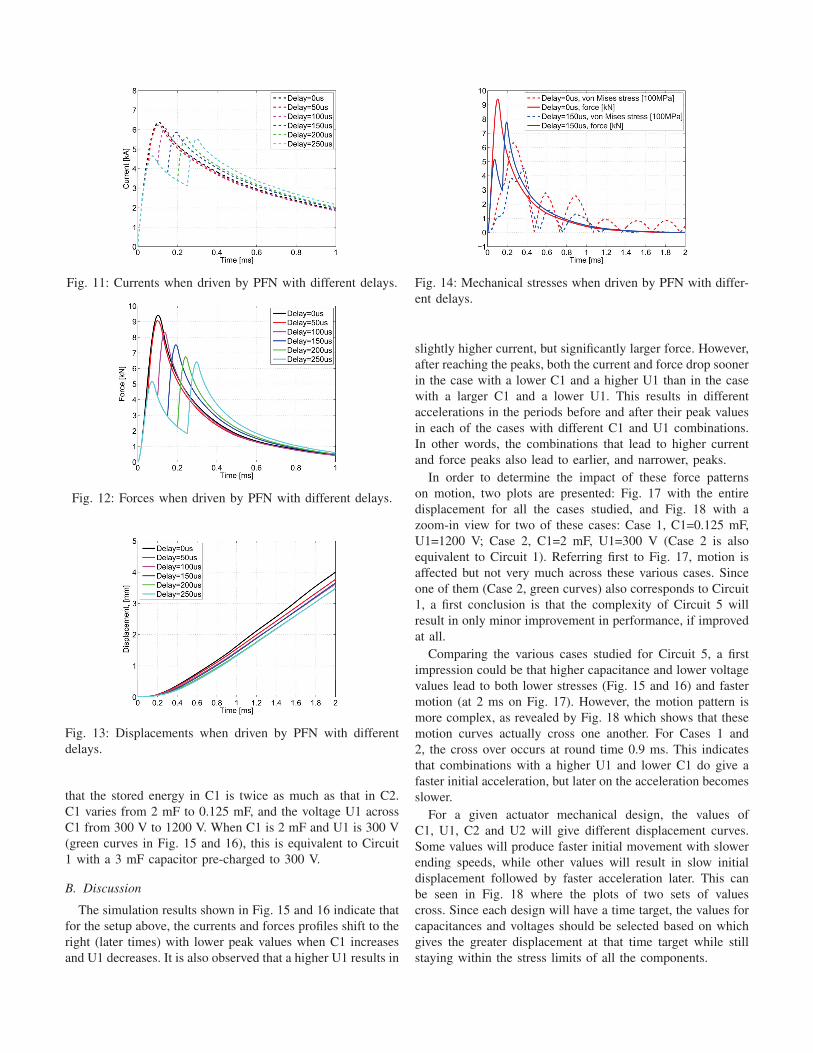
Fig. 11: Currents when driven by PFN with different delays.
Fig. 12: Forces when driven by PFN with different delays.
Fig. 13: Displacements when driven by PFN with different
delays.
that the stored energy in C1 is twice as much as that in C2.
C1 varies from 2 mF to 0.125 mF, and the voltage U1 across
C1 from 300 V to 1200 V. When C1 is 2 mF and U1 is 300 V
(green curves in Fig. 15 and 16), this is equivalent to Circuit
1 with a 3 mF capacitor pre-charged to 300 V.
B. Discussion
The simulation results shown in Fig. 15 and 16 indicate that
for the setup above, the currents and forces profiles shift to the
right (later times) with lower peak values when C1 increases
and U1 decreases. It is also observed that a higher U1 results in
Fig. 14: Mechanical stresses when driven by PFN with differ-
ent delays.
slightly higher current, but significantly larger force. However,
after reaching the peaks, both the current and force drop sooner
in the case with a lower C1 and a higher U1 than in the case
with a larger C1 and a lower U1. This results in different
accelerations in the periods before and after their peak values
in each of the cases with different C1 and U1 combinations.
In other words, the combinations that lead to higher current
and force peaks also lead to earlier, and narrower, peaks.
In order to determine the impact of these force patterns
on motion, two plots are presented: Fig. 17 with the entire
displacement for all the cases studied, and Fig. 18 with a
zoom-in view for two of these cases: Case 1, C1=0.125 mF,
U1=1200 V; Case 2, C1=2 mF, U1=300 V (Case 2 is also
equivalent to Circuit 1). Referring first to Fig. 17, motion is
affected but not very much across these various cases. Since
one of them (Case 2, green curves) also corresponds to Circuit
1, a first conclusion is that the complexity of Circuit 5 will
result in only minor improvement in performance, if improved
at all.
Comparing the various cases studied for Circuit 5, a first
impression could be that higher capacitance and lower voltage
values lead to both lower stresses (Fig. 15 and 16) and faster
motion (at 2 ms on Fig. 17). However, the motion pattern is
more complex, as revealed by Fig. 18 which shows that these
motion curves actually cross one another. For Cases 1 and
2, the cross over occurs at round time 0.9 ms. This indicates
that combinations with a higher U1 and lower C1 do give a
faster initial acceleration, but later on the acceleration becomes
slower.
For a given actuator mechanical design, the values of
C1, U1, C2 and U2 will give different displacement curves.
Some values will produce faster initial movement with slower
ending speeds, while other values will result in slow initial
displacement followed by faster acceleration later. This can
be seen in Fig. 18 where the plots of two sets of values
cross. Since each design will have a time target, the values for
capacitances and voltages should be selected based on which
gives the greater displacement at that time target while still
staying within the stress limits of all the components.

Fig. 15: Currents of Circuit 5 with different C1 and U1.
Fig. 16: Forces of Circuit 5 with different C1 and U1.
Fig. 17: Displacements of Circuit 5 with different C1 and U1.
Fig. 18: Zoomed-in displacements of Case 1 and Case 2.
Accordingly, Circuit 5 is more likely to be favorable when
the time target is really short. It will give slightly faster
acceleration within that time target at the cost of an additional
diode and increased stress levels. In Cases 1 and 2, for
example, if the time target is 0.6 ms, Case 1 with Circuit 5
gives a faster acceleration; if the time target is 1.2 ms, however,
Case 2 with Circuit 1 shows better performance.
VI. EXPERIMENTAL VERIFICATION
A prototype was fabricated to validate the accuracy of the
model and simulation. It is shown in Fig. 19. Details regarding
the electrical and structural design can be found in [23]. The
prototype has the same dimensions and materials used in the
FEA model.
Fig. 19: FMS prototype assembly.
Fig. 20: Simulation and measurement results.
This model in the finite element domain has been verified
by measurements. Fig. 20 shows the comparison of the test
results of the prototype driven by a 2 mF capacitor bank pre-
charged to 300 V, and the simulation results obtained from
FEA simulation of the modeled prototype driven based on
Circuit 1. Both the discharging current in the coil and the
displacement of the movable parts match well with each other
in the simulation and experiment. The current peaks at 4.5
kA at about 160 us and then drops slowly down to 1.5 kA at
1 ms, and 0.5 kA at 2 ms. The movable parts start moving
at around 200 us; they reach 0.9 mm at 1 ms and 2.2 mm

at 2 ms. The experimental data has verified the FEA model
presented in the previous sections and therefore the study of
drive circuit analysis based on such model is supported.
VII. CONCLUSIONS
This paper has presented an investigation of different
electric drive circuits used in Thomson coil actuators. Five
different drive circuits are evaluated. Comprehensive FEA
simulation, confirmed by experimental studies, have revealed
that:
1) The circuits come in two broad categories, single and
multiple pulse circuits. With two or more pulses, the PFN
decouples the peak value and the frequency of the current
pulse, providing an additional degree of freedom for the
designer. With lower peaks, the PFN circuits result in slightly
lower actuation speed compared to single pulse circuits, with
the same amount of stored energy. However, they significantly
reduce the mechanical stress on the structure, as well as
the peak current the electrical components are exposed to.
Whether single of multiple pulses is better depends therefore
on rating margins. For instance if the load being moved is
large compared to the moving disk, the disk can be made
heavier to sustain higher forces, resulting in single-pulse
circuits being better, and vice versa.
2) The single switch circuits such as Circuit 1 and Circuit 2
with a single pulse can drive the actuator to a comparable
speed; however, the control switch in Circuit 1 is exposed to
less current surge stress.
3) Circuit 3 generates a bidirectional current. It does not drive
the actuator any faster than Circuits 1 and 2. The current
oscillation can cause vibration of the moving structure and
the circuit requires an unpolarized capacitor.
4) The PFN drive circuit is an attractive solution when the
discharge current expected from a single pulse exceeds the
current rating of the available semiconductor switches. The
reduction in peak force can also be advantageous in reducing
the moving disk mass, for a given stress level.
5) The two-stage drive circuit is more complex than the
single-pulse circuit options. It will provide slightly better
performance only in specific situations where travel is
particularly short and the moving disk can be reinforced
to accommodate higher stress levels, without impacting
acceleration in a significant way.
6) The FEA simulation has been verified by a prototype. The
measured movement and current transients match very well
with the simulated results based on the same FEA model
used in the drive circuit study.
REFERENCES
[1] C. M. Franck, “HVDC circuit breakers: A review iden-
tifying future research needs,” Power Delivery, IEEETransactions on, vol. 26, no. 2, pp. 998–1007, 2011.
[2] C. Peng, J. Wen, G. Ma, X. Wang, Z. Liu, and K. Yu,
“Analysis and simulation on current commutation of the
DC transfer switches in UHVDC transmission systems,”
Proceedings of the Chinese Society for Electrical Engi-neering, vol. 31, no. 36, pp. 1–7, 2011.
[3] C. Peng, J. Wen, W. Xiuhuan, Z. Liu, Z. Shen, and
K. Yu, “Development of DC Transfer Switch in Ultra
High Voltage DC Transmission Systems,” Proceedings ofthe Chinese Society for Electrical Engineering, vol. 16,
p. 020, 2012.
[4] J. Hafner and B. Jacobson, “Proactive Hybrid HVDC
Breakers-A key innovation for reliable HVDC grids,”
CIGRE paper, vol. 264, 2011.
[5] C. Peng and A. Q. Huang, “A protection scheme against
DC faults VSC based DC systems with bus capacitors,”
in Applied Power Electronics Conference and Exposition(APEC), 2014 Twenty-Ninth Annual IEEE, March 2014,
pp. 3423–3428.
[6] A. Burnett, C. Oates, and C. Davidson, “High voltage dc
circuit breaker apparatus,” Sep. 6 2013, WO Patent App.
PCT/EP2012/053,574.
[7] Y. Wang and R. Marquardt, “Future HVDC-grids em-
ploying modular multilevel converters and hybrid DC-
breakers,” in Power Electronics and Applications (EPE),2013 15th European Conference on, 2013, pp. 1–8.
[8] C. Peng, A. Q. Huang, M. A. Rezaei, X. Huang, and
M. Steurer, “Development of Medium Voltage Solid-
State Fault Isolation Device for Ultra-Fast Protection of
Distribution System,” in The 40th Annual Conference ofthe IEEE Industrial Electronics Society. IEEE, Oct.
2014.
[9] S. Basu and K. Srivastava, “Analysis of a fast acting
circuit breaker mechanism part i: Electrical aspects,”
Power Apparatus and Systems, IEEE Transactions on,
no. 3, pp. 1197–1203, 1972.
[10] ——, “Analysis of a fast acting circuit breaker mecha-
nism, part ii : Thermal and mechanical aspects,” PowerApparatus and Systems, IEEE Transactions on, vol. PAS-
91, no. 3, pp. 1203–1211, May 1972.
[11] R. Rajotte and M. G. Drouet, “Experimental analysis of a
fast acting circuit breaker mechanism: Electrical aspects,”
Power Apparatus and Systems, IEEE Transactions on,
vol. 94, no. 1, pp. 89–96, 1975.
[12] A. M. S. Atmadji, “Direct current hybrid breakers: A
design and its realization,” Ph.D. dissertation, Technis-
che Universiteit Eindhoven, Eindhoven, The Netherlands,
May 2000.
[13] B. Roodenburg, A. Taffone, E. Gilardi, S. Tenconi,
B. Evenblij, and M. Kaanders, “Combined zvs–zcs topol-
ogy for high-current direct current hybrid switches: de-
sign aspects and first measurements,” Electric PowerApplications, IET, vol. 1, no. 2, pp. 183–192, 2007.
[14] M. Tsukima, T. Takeuchi, K. Koyama, and H. Yoshiyasu,
“Development of a high-speed electromagnetic repulsion
mechanism for high-voltage vacuum circuit breakers,”
Electrical Engineering in Japan, vol. 163, no. 1, pp. 34–
40, 2008.
[15] A. Bissal, J. Magnusson, E. Salinas, G. Engdahl, and
A. Eriksson, “On the design of ultra-fast electromechani-

cal actuators: A comprehensive multi-physical simulation
model,” Electromagnetic Field Problems and Applica-tions (ICEF), 2012 Sixth International Conference on,
pp. 1–4, June 2012.
[16] V. Puumala and L. Kettunen, “Electromagnetic design
of ultrafast electromechanical switches,” Power Delivery,IEEE Transactions on, vol. 30, no. 3, pp. 1104–1109,
June 2015.
[17] C. Peng, I. Husain, and A. Huang, “Evaluation of Design
Variables in Thompson Coil based Operating Mecha-
nisms for Ultra-Fast Opening in Hybrid AC and DC Cir-
cuit Breakers,” in Applied Power Electronics Conferenceand Exposition, Thirtieth Annual IEEE, 2015.
[18] Y. Kishida, K. Koyama, H. Sasao, N. Maruyama, and
H. Yamamoto, “Development of the high speed switch
and its application,” in Industry Applications Conference,1998. Thirty-Third IAS Annual Meeting. The 1998 IEEE,
vol. 3, Oct 1998, pp. 2321–2328 vol.3.
[19] M. Steurer, K. Frohlich, W. Holaus, and K. Kalteneg-
ger, “A novel hybrid current-limiting circuit breaker
for medium voltage: principle and test results,” PowerDelivery, IEEE Transactions on, vol. 18, no. 2, pp. 460–
467, 2003.
[20] J.-M. Meyer and A. Rufer, “A DC hybrid circuit breaker
with ultra-fast contact opening and integrated gate-
commutated thyristors (IGCTs),” Power Delivery, IEEETransactions on, vol. 21, no. 2, pp. 646–651, 2006.
[21] Z. Wang, J. He, X. Yin, J. Lu, D. Hui, and H. Zhang,
“10kV High Speed Vacuum Switch With Electromag-
netic Repulsion Mechanism,” Transactions of ChinaElectrotechnical Society, vol. 24, no. 11, pp. 68–75,
2009.
[22] C. W. Kimblin, “Development of current limiter using
vacuum arc current commutation. Phase 2: Maximizing
the current rating of a single 72kV device using a min-
imum amount of parallel capacitance.” NASA STI/ReconTechnical Report N, vol. 77, p. 33427, Oct. 1979.
[23] C. Peng, I. Husain, A. Huang, B. Lequesne, and
R. Briggs, “A Fast Mechanical Switch for Medium
Voltage Hybrid DC and AC Circuit Breakers,” in IEEEEnergy Conversion Conference and Expo, 2015, 2015.