drager primus service manual en
DESCRIPTION
tech description maint proceduresTRANSCRIPT

5132.3009036004
Revision 6.0
Because you care
Technical DocumentationPrimusAnaesthetic Workstation


All
right
s re
serv
ed. C
opyr
ight
rese
rved
.K5
1323
00IE
CIV
Z.fm
02.
06.0
6
I
Contents
General
1 Symbols and Definitions 3
2 Notes 3
Function Description
1 General 7
1.1 Medical purpose ..................................................................................................................... 7
1.2 Product classification ............................................................................................................. 8
1.3 Protection classes .................................................................................................................. 8
1.4 Short description of Primus ................................................................................................... 9
1.4.1 Ventilator .................................................................................................................. 9
1.4.2 Breathing system ...................................................................................................... 9
1.4.3 Mixer (fresh gas metering) .................................................................................... 10
1.4.4 Monitor control panel .............................................................................................. 11
1.4.5 Options ................................................................................................................... 12
1.5 Primus component structure ............................................................................................... 12
1.5.1 NEUTRAL POINT PCB .......................................................................................... 12
1.5.2 Graphical User Interface (GUI) ............................................................................... 13
1.5.3 Mixer ....................................................................................................................... 13
1.5.4 VGC (Ventilation and Gas Controller) .................................................................... 13
1.5.5 Power pack ............................................................................................................. 13
1.5.6 Cylinder pressure regulator .................................................................................... 13
2 NEUTRAL POINT PCB 15

All
right
s re
serv
ed. C
opyr
ight
rese
rved
.K5
1323
00IE
CIV
Z.fm
02.
06.0
6
II
Contents
3 GUI 17
3.1 Monitor Control Panel (MoBi) ...............................................................................................17
3.1.1 MONITOR CONTROL PANEL PCB .......................................................................19
3.2 S-Box (interface box) ............................................................................................................20
3.2.1 BACKPLANE PCB ..................................................................................................21
3.2.2 SpO2 sampling function (option) .............................................................................22
4 Patient gas module 23
4.1 Version PGM2 ......................................................................................................................23
4.1.1 ILCA2 function ........................................................................................................26
4.1.2 PGM2 with Pato O2 sensor ....................................................................................28
4.1.3 PGM2 with Servomex O2 sensor ...........................................................................30
4.1.4 Pneumatics of the PGM2 ........................................................................................32
4.2 Version PGM ........................................................................................................................34
4.2.1 PGM pneumatic components .................................................................................37
4.3 Operating modes ..................................................................................................................39
4.3.1 "Reduced Accuracy" mode (PGM only) ..................................................................39
4.3.2 "ISO" mode (ISO accuracy) (PGM/PGM2) .............................................................39
4.3.3 "Full Accuracy" mode (PGM only) ..........................................................................39
4.3.4 "Standby" response of the Primus (PGM/PGM2) ...................................................39
4.3.5 IRIA/ILCA2 calibration ...........................................................................................39
4.3.6 Auto-Wake-up function ..........................................................................................39
4.3.7 O2 sensor/Servomex ..............................................................................................39
4.4 PGM/PGM2 electronics ........................................................................................................40
4.4.1 MOPS PCB (PGM/PGM2) ......................................................................................40
4.4.2 AMO IRIA PCB (PGM) ............................................................................................40
4.4.3 AMO ILCA2 PCB (PGM2) .......................................................................................40
4.4.4 AMO O2 PUMP PCB (PGM) ..................................................................................40
4.4.5 AMO MFM PCB (PGM2) ........................................................................................40
4.4.6 AMO FLOW ILCA PCB (PGM/PGM2) ....................................................................41

All
right
s re
serv
ed. C
opyr
ight
rese
rved
.K5
1323
00IE
CIV
Z.fm
02.
06.0
6
III
Contents
5 Mixer 43
5.1 Operating modes .................................................................................................................. 46
5.1.1 10 VA mode ............................................................................................................ 46
5.1.2 'Normal' mode ........................................................................................................ 46
5.2 Layout ................................................................................................................................... 46
5.2.1 MIXER PCB ............................................................................................................ 46
5.2.2 PRIMUS CPU PCB (mixer) .................................................................................... 47
5.3 Gas inlet block (AIR, O2 and N2O) ...................................................................................... 48
5.3.1 Pneumatic components, gas inlet block ................................................................. 50
5.3.2 Pressure status LEDs ............................................................................................. 52
5.4 Mixer block ........................................................................................................................... 55
5.5 Pneumatic system ................................................................................................................ 56
5.5.1 VMIX valves ........................................................................................................... 57
5.5.2 PDMIX and RM ...................................................................................................... 57
5.5.3 PTANK (pressure sensor) ....................................................................................... 57
5.5.4 VTANK valve .......................................................................................................... 57
5.5.5 VMGS (fresh gas flow valve) .................................................................................. 57
5.5.6 PDMGSHI / PDMGSLO (differential pressure sensors) ......................................... 57
5.5.7 PSYS (pressure sensor) ......................................................................................... 57
5.5.8 VSWAK (A-cone valve) .......................................................................................... 58
5.5.9 VBAK (safety valve) ............................................................................................... 58
5.5.10 TEMPTANK / TEMPBLOCK (temperature sensors) ............................................... 58
5.5.11 VSFC (safety O2 adjuster) ..................................................................................... 58
5.5.12 VO2+ (flush button) ................................................................................................ 58

All
right
s re
serv
ed. C
opyr
ight
rese
rved
.K5
1323
00IE
CIV
Z.fm
02.
06.0
6
IV
Contents
6 VGC 59
6.1 VGC electronics ....................................................................................................................61
6.1.1 VGC POWER PCB .................................................................................................61
6.1.2 PRIMUS ANALOG PCB .........................................................................................61
6.2 Piston cylinder unit (PCU) ....................................................................................................62
6.3 VGC pneumatic block ...........................................................................................................64
6.4 VGC pneumatic system ........................................................................................................65
6.5 Interface plate .......................................................................................................................67
6.6 Breathing system ..................................................................................................................69
6.6.1 Compact breathing system pneumatic components ...............................................72
6.7 Automatic ventilation ............................................................................................................73
6.7.1 Inspiration ...............................................................................................................73
6.7.2 Expiration ................................................................................................................75
6.8 Manual ventilation .................................................................................................................77
6.8.1 Inspiration ...............................................................................................................77
6.8.2 Expiration ................................................................................................................78
6.9 Spontaneous breathing .........................................................................................................79
6.9.1 Inspiration ...............................................................................................................79
6.9.2 Expiration ................................................................................................................80
7 Ventilation modes with software version 2.n or higher 81
7.1 “Volume Mode” .....................................................................................................................81
7.2 “Pressure Mode” ...................................................................................................................84
7.3 “Pressure Support Mode” .....................................................................................................87
7.4 “Man./Spont Mode” ...............................................................................................................88
7.5 Switching ventilation modes .................................................................................................89
7.6 HLM mode ............................................................................................................................89

All
right
s re
serv
ed. C
opyr
ight
rese
rved
.K5
1323
00IE
CIV
Z.fm
02.
06.0
6
V
Contents
8 Power pack 91
8.1 Power pack input .................................................................................................................. 91
8.2 Power switch ........................................................................................................................ 92
8.3 Output voltages and currents ............................................................................................... 92
8.4 Secondary connector ........................................................................................................... 93
8.5 UPS batteries ....................................................................................................................... 93
8.6 Power pack CAN communication ......................................................................................... 94
8.7 Power failure warning ........................................................................................................... 94
9 Operating modes 95
9.1 Cold start .............................................................................................................................. 95
9.2 Standby mode ...................................................................................................................... 95
9.3 Shutdown ............................................................................................................................. 95
9.4 Safety mode ......................................................................................................................... 95
9.4.1 Safety O2 flow ........................................................................................................ 95
9.5 Alarm system ........................................................................................................................ 96
10 Cylinder pressure reducer 97
11 Vaporizer 101
12 Bronchial aspirator 103
12.1 Intended use ....................................................................................................................... 103
12.2 Device types ....................................................................................................................... 103
12.2.1 Variants ................................................................................................................. 103
12.3 Bronchial aspirator with ejector .......................................................................................... 103
12.3.1 Pneumatics (ejector) ............................................................................................ 104
12.4 Bronchial aspirator with vacuum ........................................................................................ 105
12.4.1 Pneumatics (vacuum) ........................................................................................... 106
13 Block diagrams and pneumatic components layout 109
13.1 Introduction ......................................................................................................................... 109

All
right
s re
serv
ed. C
opyr
ight
rese
rved
.K5
1323
00IE
CIV
Z.fm
02.
06.0
6
VI
Contents
Maintenance Procedures
1 Safety precautions 123
2 Rear panel 125
2.1 Rear panel removal ............................................................................................................125
2.2 Rear panel fitting .................................................................................................................125
2.2.1 Rear panel final check ..........................................................................................125
3 Replacing bronchial suction device bacterial filter 127
4 Replacing filter mat on PGM fan 129
5 Replacing bacterial filter and Nafion tube in PGM 131
5.1 Removing the PGM ............................................................................................................131
5.1.1 Removing the PGM housing .................................................................................131
5.2 Replacing the bacterial filter ...............................................................................................133
5.3 Replacing the Nafion tube .................................................................................................133
5.4 Fitting the PGM housing (new) ...........................................................................................134
6 Cleaning or replacing filter mat in housing cover 137
6.1 Filter mat removal ...............................................................................................................137
6.1.1 Filter mat fitting .....................................................................................................138
7 Replacing filter mat in power pack 139
8 Replacing UPS batteries 141
8.1 Power pack removal ...........................................................................................................141
8.2 Removing UPS batteries ....................................................................................................142
8.3 Fitting UPS batteries ...........................................................................................................144
8.4 Fitting the power pack .........................................................................................................146

All
right
s re
serv
ed. C
opyr
ight
rese
rved
.K5
1323
00IE
CIV
Z.fm
02.
06.0
6
VII
Contents
9 Cleaning or replacing large and small filter mats in VGC 147
9.1 Removal of large filter mat ................................................................................................. 147
9.1.1 Fitting of large filter mat ........................................................................................ 149
9.2 Removal of small filter mat ................................................................................................. 149
9.2.1 Fitting of small filter mat ....................................................................................... 150
10 Replacing bag upper roller diaphragm 151
11 Replacing the lower rolling seal (VGC) 153
11.1 Removing the VGC ............................................................................................................ 153
11.2 Removing the piston-cylinder unit ...................................................................................... 158
11.2.1 Removing/Fitting the lower rolling seal ................................................................. 162
11.3 Mounting piston-cylinder unit .............................................................................................. 168
12 Replacing pressure regulators PRPN2O, PRPAIR, PRPO2 173
12.1 Removing gas inlet block pressure regulators ................................................................... 173
12.2 Fitting pressure regulators .................................................................................................. 174
13 Replacing CPU PRIMUS PCB lithium battery 179
13.1 Removing mixer ................................................................................................................. 179
13.2 Removing mixer cover ........................................................................................................ 182
13.3 Replacing the lithium battery .............................................................................................. 183
13.4 Fitting mixer cover .............................................................................................................. 184
13.5 Mixer fitting ......................................................................................................................... 184
14 Replacing PEEP diaphragm and MAN/SPONT diaphragm 185
15 Pressure regulator major overhaul 189
15.1 Safety precautions .............................................................................................................. 189
15.2 Required spare parts .......................................................................................................... 190
15.3 Service Equipment Required .............................................................................................. 191
15.4 Removing the pressure regulator ....................................................................................... 192
15.5 Replacing the “Major Overhaul” spare parts set ................................................................. 194

All
right
s re
serv
ed. C
opyr
ight
rese
rved
.K5
1323
00IE
CIV
Z.fm
02.
06.0
6
VIII
Contents
Schematics and Diagrams
1 Primus pneumatic components diagram 203
2 Schematics and Diagrams 209
Annex
Parts catalog
Test List
Technical Information

1
General

2

5132.300
All
right
s re
serv
ed. C
opyr
ight
rese
rved
.Ve
rsio
n 3.
0_ R
elea
sed_
Prin
ted
on_0
2.06
.06_
Gen
eral
_Tec
hnic
al_D
ocum
enta
tion.
fm
3
Primus General
1 Symbols and Defini-tions
2 Notes This Technical Documentation conforms to the IEC 60601-1 standard.
Read each step in every procedure thoroughly before beginning any test. Always use the proper tools and specified test equipment. If you deviate from the instructions and/or recommendations in this Technical Documentation, the equipment may operate improperly or unsafely, or the equipment could be damaged.
It is our recommendation to use only Dräger parts and supplies.
The maintenance procedures described in this Technical Documentation may be performed by qualified service personnel only. These maintenance proce-dures do not replace inspections and servicing by the manufacturer.
The information in this Technical Documentation is confidential and may not be disclosed to third parties without the prior written consent of the manufac-turer.
This Technical Documentation is for the purpose of information only. Product descriptions found in this Technical Documentation are in no way a substitute for reading and studying the Instructions for Use/Operating Manual enclosed with the product at the time of delivery.
WARNINGA WARNING statement provides important information about a poten-tially hazardous situation which, if not avoided, could result in death or serious injury.
CAUTIONA CAUTION statement provides important information about a potentially hazardous situation which, if not avoided, may result in minor or moderate injury to the user or patient or in damage to the equipment or other prop-erty.
NOTEA NOTE provides additional information intended to avoid inconvenience during operation.
Definitions according to German standard DIN 31051:Inspection = examination of actual conditionMaintenance = measures to maintain specified conditionRepair = measures to restore specified conditionServicing = inspection, maintenance, and repair

All
right
s re
serv
ed. C
opyr
ight
rese
rved
.Ve
rsio
n 3.
0_ R
elea
sed_
Prin
ted
on_0
2.06
.06_
Gen
eral
_Tec
hnic
al_D
ocum
enta
tion.
fm
4 5132.300
General Primus
Know-how contained in this Technical Documentation is subject to ongoing change through research and development and Dräger Medical reserves the right to make changes to this Technical Documentation without notice.
NOTEUnless otherwise stated, reference is made to laws, regulations or stan-dards (as amended) applicable in the Federal Republic of Germany for equipment used or serviced in Germany. Users or technicians in all other countries must verify compliance with local laws or applicable international standards.

5
Function Description

6

5132.300
All
right
s re
serv
ed. C
opyr
ight
rese
rved
.Ve
rsio
n 2.
0_ R
elea
sed_
Prin
ted
on_0
2.06
.06_
F513
2300
T01_
Allg
emei
nes.
fm
7
Primus Function Description
1 General
1.1 Medical purpose Primus is an anaesthetic workstation for automatic and manual ventilation and spontaneous breathing, usable for adults, children and infants.
Application:– Inhalation anesthesia in rebreathing systems.– Inhalation anesthesia in virtually closed systems for low-flow and mini-
mum-flow applications.– Inhalation anesthesia in non-rebreathing systems with separate fresh gas
output for connection of “Bain” or “Magill” system, for example, with a fresh gas flow of 0.2 L/min to 18 L/min.
Changed ventilation modes (software 2.n or higher):– Volume-controlled ventilation “Volume Mode”. Switchable functions:
• Synchronization.• Pressure support (optional).
– Pressure-controlled ventilation “Pressure Mode” Switchable functions:• Synchronization.• Pressure support (optional).
– Manual ventilation “MAN”.– Spontaneous breathing “SPONT”.– Pressure-assisted ventilation “Pressure Support” (optional).
Ventilation modes (up to software 1.06):– Volume-controlled ventilation “IPPV, SIMV”.– Pressure-controlled ventilation “PCV”– Manual ventilation “MAN”.– Spontaneous breathing “SPONT”.
Displayed values:– Peak pressure “Ppeak”, mean pressure “Pmean”, plateau pressure
“Pplat, PEEP”.– Expiratory minute volume “MV”, tidal volume “VT”, respiratory frequency
“f”.– Inspiratory and expiratory concentrations of O2, N2O, anesthetic gas and
CO2.– System compliance and leakage minute volume.– Functional oxygen saturation “SpO2” and pulse rate (optional).

All
right
s re
serv
ed. C
opyr
ight
rese
rved
.Ve
rsio
n 2.
0_ R
elea
sed_
Prin
ted
on_0
2.06
.06_
F513
2300
T01_
Allg
emei
nes.
fm
8 5132.300
Function Description Primus
Curve diagrams:– Airway pressure “Paw”.– Inspiratory and expiratory flow “V”.– Inspiratory and expiratory concentrations of O2, CO2 and anesthetic gas.– Plethysmogram (optional).– P/V loops and flow/V loops (optional in software 2.n or higher).
Bargraph:– Display of inspiratory tidal volume, expiratory tidal volume and leakage
tidal volume.– Volumeter.– Econometer (optional in software 2.n or higher).
Time trends of measured values (trends) are additionally available.
Monitoring:– By programmable alarm limits which can be adjusted automatically to the
respective ventilation situation.
Monitored parameters:– Airway pressure “Paw”.– Expiratory minute volume “AMV”.– Apnea (deactivated in heart-lung machine mode (HLM mode)).– Inspiratory and expiratory anesthetic gas concentrations.– Detection of anesthetic gas mixtures.– Inspiratory O2 and N2O concentrations (breathing-phase independent
measurement in HLM mode).– Inspiratory and expiratory CO2 concentrations (breathing-phase indepen-
dent measurement in HLM mode).– Optional: Oxygen saturation (alarms deactivated in HLM mode), pulse
rate.
1.2 Product classifica-tion
– Class II b, according to rules 2, 9 and 11 of the Medical Products Direc-tive.
1.3 Protection classes – Protection class I, type B according to EN 60601-1.– With optional SpO2: Protection class I, type BF.

5132.300
All
right
s re
serv
ed. C
opyr
ight
rese
rved
.Ve
rsio
n 2.
0_ R
elea
sed_
Prin
ted
on_0
2.06
.06_
F513
2300
T01_
Allg
emei
nes.
fm
9
Primus Function Description
1.4 Short description of Primus
The following sections provide an overview of the Primus components.
1.4.1 Ventilator
Figure 1 Ventilator with breathing system
The electronically controlled and driven ventilator has the following features:– Tidal volumes of 20 mL (10 mL with software 2.n or higher) to 1400 mL at
frequencies of 3/min to 80/min.– Peak flow of up to 150 L/min.– Ventilation modes such as IPPV, PCB, SIMV (plus adjustable trigger, plus
adjustable PEEP) and MAN/SPONT (up to software 1.n).– Ventilation modes such as volume mode, pressure mode, pressure sup-
port (optional) and MAN/SPONT with switchable synchronization and pressure assistance (optional).
1.4.2 Breathing system The breathing system comprises the following components:– Integrated absorber, either reusable or disposable.– Electronic interfaces for inspiratory and expiratory flow measurement.– Direct patient section heating is integrated into the valve plate of the
breathing system.– Pneumatic interface to ventilator.– Fresh gas isolation and minimized compliance.

All
right
s re
serv
ed. C
opyr
ight
rese
rved
.Ve
rsio
n 2.
0_ R
elea
sed_
Prin
ted
on_0
2.06
.06_
F513
2300
T01_
Allg
emei
nes.
fm
10 5132.300
Function Description Primus
1.4.3 Mixer (fresh gas meter-ing)
The electronic mixer offers the following features:– Gas metering for O2, N2O and AIR.– Metering range from 200 mL/min to 18 L/min.– Alarm monitoring for the pressure values of the central supply (CS) and
the cylinder supply. LEDs on the front panel indicate the pressure status.– ORC function for low-flow and minimum-flow applications.– O2 flush and mechanical safety O2 adjuster (see Figure 2).
Figure 2 O2 flush (O2+), mechanical safety O2 adjuster
– Double Vapor plug-in system with interlock.– Optional external A-cone as fresh gas outlet.

5132.300
All
right
s re
serv
ed. C
opyr
ight
rese
rved
.Ve
rsio
n 2.
0_ R
elea
sed_
Prin
ted
on_0
2.06
.06_
F513
2300
T01_
Allg
emei
nes.
fm
11
Primus Function Description
1.4.4 Monitor control panel
Figure 3 Monitor control panel
The parameters for fresh-gas flow control, ventilation, and gas monitoring are displayed on a 12-inch color screen.
The following parameters are monitored:– Airway pressure.– Inspiratory and expiratory flow.– Circle system leakage.– Inspiratory and expiratory O2 concentration.– CO2 measurement and anesthetic gas measurement.– Anesthetic gas detection.– Quantitative measurement of mixed-gas values and MAC calculation
(age-relevant).
A data view, a trend view (graphical) and a log view can be selected.
As from software release 2.n the following settings are possible:– Free configuration of 3 real-time curves and different numerical values.– Body-weight-relevant ventilator presettings (Vt and frequency) and age-
relevant calculation of minimum alveolar concentration (MAC ) according to “Mapleson” as well as age-relevant scaling of volumeter and influence on ventilation monitoring.
All
right
s re
serv
ed. C
opyr
ight
rese
rved
.Ve
rsio
n 2.
0_ R
elea
sed_
Prin
ted
on_0
2.06
.06_
F513
2300
T01_
Allg
emei
nes.
fm
12 5132.300
Function Description Primus
The safety concept incorporates the following tests:– Automatic self-test with mixer test, ventilator test and test of the breathing
system.– Test and automatic calibration of all sensors.
1.4.5 Options Primus is prepared for future upgrading with the following options:– Integrated SpO2 measurement.– Consumption-free O2 measurement (with software 2.n or higher).– PAW preview – display of expected airway pressure curve when chang-
ing parameters.– P/V and flow/V loops (with software 2.n or higher).– Econometer function (with software 2.n or higher).– Additional ventilation modes (e.g. autoflow, CPAP).– Additional languages available for display texts.
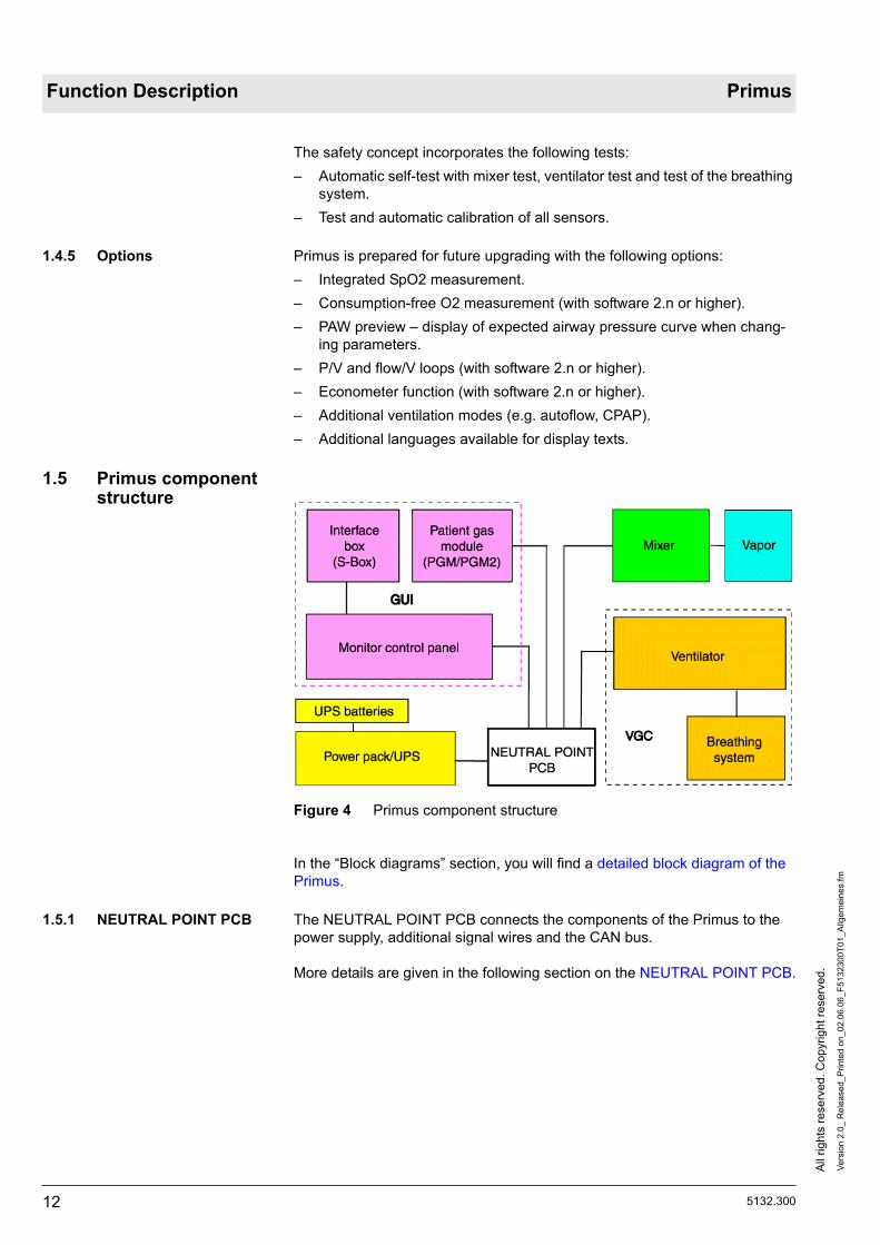
1.5 Primus component structure
Figure 4 Primus component structure
In the “Block diagrams” section, you will find a detailed block diagram of the Primus.
1.5.1 NEUTRAL POINT PCB The NEUTRAL POINT PCB connects the components of the Primus to the power supply, additional signal wires and the CAN bus.
More details are given in the following section on the NEUTRAL POINT PCB.

5132.300
All
right
s re
serv
ed. C
opyr
ight
rese
rved
.Ve
rsio
n 2.
0_ R
elea
sed_
Prin
ted
on_0
2.06
.06_
F513
2300
T01_
Allg
emei
nes.
fm
13
Primus Function Description
1.5.2 Graphical User Interface (GUI)
The GUI has the following components:– On the Monitor Control Panel (MoBi) the ventilation mode is displayed.
Limit and target values are specified and the ventilation and anesthesia parameters are displayed.
– S-Box (Interface box). PC interfaces and optional measuring functions such as SpO2 and BISTM.
– Patient Gas Module (PGM) for measurement of O2, CO2 and anesthetic gas.
For more details refer to the section headed GUI.
1.5.3 Mixer The mixer comprises the following function units:– Electronically controlled and monitored mixer.– Vapor plug-in system for one or two conventional vaporizer types.– External fresh gas outlet, A-cone (optional).– Pressure monitoring for CS and compressed gas cylinders.
More details are given in the following section on the mixer.
1.5.4 VGC (Ventilation and Gas Controller)
The VGC comprises the following function units:– Electronically controlled and driven ventilator.– Integrated breathing system for “low flow” and “minimum flow” applica-
tions.
For more details refer to the section headed VGC.
1.5.5 Power pack The power pack comprises:– Switched-mode power supply unit.– Uninterruptible power supply (UPS) with one battery pack consisting of
two 12 V lead-gel batteries.– Battery charging management.
For more details refer to the section headed Power pack.
1.5.6 Cylinder pressure regu-lator
The cylinder pressure regulators reduce the pressure of the optional com-pressed gas cylinders.
For more details refer to the section headed Cylinder pressure regulators.
The function description relating to the NEUTRAL POINT PCB follows.

All
right
s re
serv
ed. C
opyr
ight
rese
rved
.Ve
rsio
n 2.
0_ R
elea
sed_
Prin
ted
on_0
2.06
.06_
F513
2300
T01_
Allg
emei
nes.
fm
14 5132.300
Function Description Primus
5132.300
All
right
s re
serv
ed. C
opyr
ight
rese
rved
.Ve
rsio
n 2.
0_ R
elea
sed_
Prin
ted
on_0
2.06
.06_
F513
2300
T02_
LP_S
tern
punk
t.fm
15
Primus Function Description
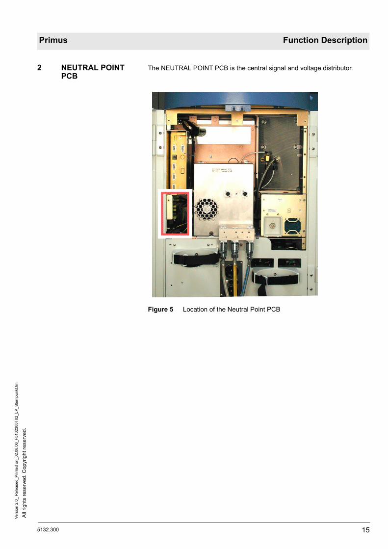
2 NEUTRAL POINT PCB
The NEUTRAL POINT PCB is the central signal and voltage distributor.
Figure 5 Location of the Neutral Point PCB

All
right
s re
serv
ed. C
opyr
ight
rese
rved
.Ve
rsio
n 2.
0_ R
elea
sed_
Prin
ted
on_0
2.06
.06_
F513
2300
T02_
LP_S
tern
punk
t.fm
16 5132.300
Function Description Primus
Figure 6 Component mounting diagram, NEUTRAL POINT PCB, for leg-end see Table 1
Table 1 Legend to Figure 6
The function description relating to the GUI follows.
Item Connector
1 Monitor Control Panel (MoBi).
2 Monitor Control Panel (MoBi).
3 Ventilation and Gas Controller (VGC).
4 Mixer B.
5 Mixer A.
6 Safety O2 flow valve (microswitch).
7 Power switch (main switch).
8 Halogen lamp
9 Jack plug (production tests).
10 PGM.
11 Power pack A.
12 Power pack B.
13 Not assigned.

5132.300
All
right
s re
serv
ed. C
opyr
ight
rese
rved
.Ve
rsio
n 5.
0_ R
elea
sed_
Prin
ted
on_0
2.06
.06_
F513
2300
T03_
GU
I.fm
17
Primus Function Description
3 GUI The following section describes the user interface (“GUI = Graphical User Interface”).
Figure 7 GUI block diagram
In the “Block diagrams” section, in the block diagram of the Primus, you will find a block diagram of the GUI.
The GUI has the following components:– MoBi (monitor control panel).– S-Box (Interface Box).– Patient Gas Module (PGM). The function description relating to the
Patienten Gas Module (PGM) follows.
3.1 Monitor Control Panel (MoBi)
Figure 8 Position of Monitor Control Panel (MoBi)
In the “Block diagrams” section, you will find a block diagram of the MoBi.

All
right
s re
serv
ed. C
opyr
ight
rese
rved
.Ve
rsio
n 5.
0_ R
elea
sed_
Prin
ted
on_0
2.06
.06_
F513
2300
T03_
GU
I.fm
18 5132.300
Function Description Primus
The user and Primus communicate via the MoBi. The MoBi display presents system and patient information. It is here that the user sets the parameters and ventilation modes.
The Patient Gas Module (PGM) is connected to the GUI.
Figure 9 Exploded view of MoBi, for legend see Table 2
Table 2 Legend to Figure 9
Item Components
1 Front panel with membrane keypad. Includes keypad membrane covering with design imprint, keys, LEDs (e.g. for CS gases), the carrier plate and the shielding, anti-glare glass screen.
2 12 inch color display (TFT, resolution: 800 x 600).
3 MONITOR CONTROL PANEL PCB (motherboard).
4 Backlight converter (display backlighting).
5 LCD800 PCB (adapter PCB for connection of different makes of display).
6 Loudspeaker.
7 Rotary transducer.
8 Control knob (central operator control element).

5132.300
All
right
s re
serv
ed. C
opyr
ight
rese
rved
.Ve
rsio
n 5.
0_ R
elea
sed_
Prin
ted
on_0
2.06
.06_
F513
2300
T03_
GU
I.fm
19
Primus Function Description
3.1.1 MONITOR CONTROL PANEL PCB
The following software is installed on the PCB:– GUI software.– Monitoring and evaluation software for the PGM.– Software for Medibus connections and SpO2.
A 2-processor system is in operation on the PCB. It comprises a Display Master (DiMa) and a Communication Master (CoMa).
The powerful DiMa processor incorporates the following components:– Motorola processor (MPC823) with 48 MHz clock frequency and 32-bit
address and data buses.– Flash-PROM (program memory).– RAM (data memory).– CAN controller.– RS232 interface for in-house development purposes. – Serial communication channel for Ethernet.
The LCD controller is a programmable logic device (“PLD”). A “DRAM” serves as the video memory.
The CoMa processor system primarily controls communication with the other Primus components.
The CoMa incorporates the following components:– Motorola processor (M68332) with 16.7 MHz clock frequency, internal 32-
bit bus and external 16-bit data bus.– Flash-PROM (program memory).– RAM (data memory).– RS232 interface for communication with the SPO2, PGM and Medibus 1 -
3 modules.– Real-time clock (RTC).– Keyboard and rotary knob scan, LED actuation and sound output.– CAN interface.
Both processor systems communicate by way of a Dual-Port RAM (DPR). This memory device is battery-buffered. The buffering is provided primarily by the UPS batteries of the Primus. If they fail, the lithium battery on the MONI-TOR CONTROL PANEL PCB ensures data is retained.
The operating voltage is provided by an unstabilized voltage of 20 V to 30 V (Vcc). DC converters on the MONITOR CONTROL PANEL PCB generate all other voltages on the PCB.
The MoBi is interconnected over the CAN bus with the other components of the Primus (power pack, mixer and VGC).
All
right
s re
serv
ed. C
opyr
ight
rese
rved
.Ve
rsio
n 5.
0_ R
elea
sed_
Prin
ted
on_0
2.06
.06_
F513
2300
T03_
GU
I.fm
20 5132.300
Function Description Primus
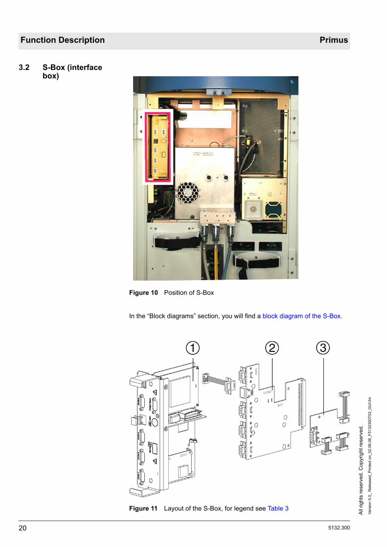
3.2 S-Box (interface box)
Figure 10 Position of S-Box
In the “Block diagrams” section, you will find a block diagram of the S-Box.
Figure 11 Layout of the S-Box, for legend see Table 3

5132.300
All
right
s re
serv
ed. C
opyr
ight
rese
rved
.Ve
rsio
n 5.
0_ R
elea
sed_
Prin
ted
on_0
2.06
.06_
F513
2300
T03_
GU
I.fm
21
Primus Function Description
Table 3 Legend to Figure 11
Figure 12 S-Box, block diagram
The S-Box as standard includes the BACKPLANE PCB and thus the exter-nally available Medibus ports (COM 1-3), IV-System (Ethernet for TIVA) and a CAN port (SABUS exclusively for debug purposes).
The S-Box is prepared for the SpO2 option.
3.2.1 BACKPLANE PCB The BACKPLANE PCB is the base component for additional modules and the insulated interfaces to external devices.
In the “Block diagrams” section, you will find a block diagram of the BACK-PLANE PCB
The BACKPLANE PCB has the following functions:– Electrical isolation and level conversion of the 3 Medibus ports (RS232).– Connects the MoBi with the CAN (SABUS) and Ethernet (TCP/IP) con-
nectors.– Connects the optional hardware (SPO2, IV-System) with the MoBi (as
from SW 1.n).
Item Components
1 Drawer unit components fully mounted.
2 BACKPLANE PCB.
3 SpO2 ADAPTER PCB (SpO2 PCB not shown).

All
right
s re
serv
ed. C
opyr
ight
rese
rved
.Ve
rsio
n 5.
0_ R
elea
sed_
Prin
ted
on_0
2.06
.06_
F513
2300
T03_
GU
I.fm
22 5132.300
Function Description Primus
3.2.2 SpO2 sampling function (option)
The SpO2 sampling function has the following tasks:– Non-invasive measurement of functional oxygen saturation in the arterial
blood. The upper and lower alarm limits are monitored on the MONITOR CONTROL PANEL PCB by the CoMa processor.
– Measurement of pulse rate.– Monitoring of the pulse rate with upper and lower alarm limits.
The SpO2 sensor essentially comprises two LEDs (light-emitting diodes) which alternatingly emit infrared light with typical wavelengths of 920 nm and 660 nm respectively. An opposing photodetector measures the radiant inten-sity. The sensor is placed on a part of the body on which arterial blood ves-sels can be X-rayed, such as the fingers, toes or bridge of the nose.
The new SpO2 sensor “DS-100A” incorporates a memory chip. The Nellcor module used in the Primus now detects only this SpO2 sensor. The new sen-sor is identifiable by the fact that all nine pins are present on the connector.
The SpO2 sensor is connected without a pre-amplifier to the module. The module communicates through a serial port with the MONITOR CONTROL PANEL PCB. On the BACKPLANE PCB the module is electrically isolated with 1.5 kV.
The function description relating to the Patienten Gas Module (PGM) follows.

5132.300
All
right
s re
serv
ed. C
opyr
ight
rese
rved
.Ve
rsio
n 5.
0_ R
elea
sed_
Prin
ted
on_0
2.06
.06_
F513
2300
T03_
PG
M.fm
23
Primus Function Description
4 Patient gas module The PGM (patient gas module) or PGM2 is an integral part of the GUI func-tional unit (see function description GUI.
There are two versions of the patient gas module:– PGM.– PGM2.
In the “Block diagrams” section, you will find the block diagrams of the PGM/PGM2 electronics
Differences between PGM2 and PGM:
4.1 Version PGM2 The following illustration shows the location of the PGM2 (rear panel of unit is open).
Figure 13 Location of the PGM2
PGM PGM2
Anesthetic gas mea-surement.
IRIA. ILCA2.
O2 sampling. Electrochemical O2 cell. Servomex sensor or Pato sensor.
O2 measurement electronics.
AMO O2 PUMP PCB AMO MFM PCB.
Pump flow. 150 mL 200 mL
Flush flow. 200 mL 250 mL

All
right
s re
serv
ed. C
opyr
ight
rese
rved
.Ve
rsio
n 5.
0_ R
elea
sed_
Prin
ted
on_0
2.06
.06_
F513
2300
T03_
PG
M.fm
24 5132.300
Function Description Primus
Figure 14 Exploded view of PGM2, for legend see Table 4
Table 4 Legend to Figure 22
Item Component
1 ILCA2 sensor head.
2 Solenoid valve V1.
3 Pump (200 mL).
4 Insulating foil.
5 MOPS PCB (central processor).
6 PCBs mounting frame.
7 AMO ILCA2 PCB (anesthetic gas analysis).
8 AMO Flow ILCA PCB (flow measurement, pump control, and valve control).
9 AMO MFM PCB (O2 analysis).
10 “Servomex” O2 sensor or “Pato” O2 sensor.
11 Filter mat.

5132.300
All
right
s re
serv
ed. C
opyr
ight
rese
rved
.Ve
rsio
n 5.
0_ R
elea
sed_
Prin
ted
on_0
2.06
.06_
F513
2300
T03_
PG
M.fm
25
Primus Function Description
The PGM2 automatically detects and measures the anesthetic gas in use - Halothane, Enflurane, Isoflurane, Desflurane or Sevoflurane. It also detects and measures mixtures of two of the above anesthetic gases. If it encounters a mixture of more than two anesthestic gases, the warning “AGas mixture” is delivered.
CO2, O2 and the anesthetic gas mixture are presented as a real-time curve.
Some of the parameters measured by the PGM2 (etCO2, inCO2 etN2O, inN2O, etO2 and inO2) are presented on the GUI as digital values.
One component of the PGM2 is the water trap. The water trap is accessible from the front panel. For position see following diagram.
Figure 15 Position of water trap
12 Bacterial filter.
13 Holder for WaterLock (water trap).
14 WaterLock.
15 Fan.
16 Solenoid valve V2.
17 Adapter board (connection board).
Item Component

All
right
s re
serv
ed. C
opyr
ight
rese
rved
.Ve
rsio
n 5.
0_ R
elea
sed_
Prin
ted
on_0
2.06
.06_
F513
2300
T03_
PG
M.fm
26 5132.300
Function Description Primus
4.1.1 ILCA2 function ILCA2 is a gas measuring module for the analgesic N2O, the anesthetic gases Halothane, Enflurane, Isoflurane, Desflurane and Sevoflurane, and for measurement of mixtures. ILCA2 conforms to the measurement accuracy specified by ISO standards.
The ILCA2 module is capable of automatically detecting the above mentioned gases.
ILCA2 module design
The ILCA2 module principally comprises the following components:– Sensor head with double-optics, pressure sensor, and electronics.– Diaphragm pump.– Pneumatic low pass.– Solenoid valve for zero calibration.– Module rack with 3 PCBs.
In the “Block diagrams” section, you will find a block diagram of the ILCA2 module.
Sensor head
The sensor head houses 2 PCBs with the following functions:– Pre-amplifier PCB for the two multi-channel detectors.– Base PCB with emitter activation, temperature regulation, absolute pres-
sure measurement and a serial EEPROM holding the serial number, set-ting and calibration data for operation of the sensor head.
The module rack of the ILCA2 module contains 4 additional PCBs with the following functions:– AMO FLOW ILCA PCB - Control of the diaphragm pump and the zero
calibration solenoid. A serial EEPROM stores the necessary data such as the serial number, hardware/software revision, control parameters etc.
– AMO ILCA2 PCB - Here the necessary supply voltages are generated and the data transfer from the ILCA2 sensor to the MOPS PCB is imple-mented.
– AMO MFM PCB - This circuit board amplifies the signal from the Ser-vomex sensor.
– MOPS PCB - Primarily delivers the data for further processing via an RS 232 interface.
Measurement principle
The measurement principle of the ILCA2 module is based on the absorption of infrared light by the various media (see Figure 16). The sensor head con-sists of a double measuring head with one emitter each which emits a broad spectrum of infrared light. The light beam passes through a cuvette, through which the gas being measured is also drawn by means of a diaphragm pump. Downstream of the cuvette the light beam hits a multi-channel detector with IR filters. The filters are dimensioned so that only the light in the absorption wavelength of the measured gases is transmitted. If a gas is present light is absorbed. The higher the partial pressure of the gas, the greater the absorp-tion of the light and the smaller the sensor signal.

5132.300
All
right
s re
serv
ed. C
opyr
ight
rese
rved
.Ve
rsio
n 5.
0_ R
elea
sed_
Prin
ted
on_0
2.06
.06_
F513
2300
T03_
PG
M.fm
27
Primus Function Description
Figure 16 Principle of multi-channel detector with IR filters
Table 5 Legend to Figure 16
Item Meaning
1 Infrared light.
2 Beam splitter.
3 Sensor chip.
4 Infrared filter.
5 Sensor window.

All
right
s re
serv
ed. C
opyr
ight
rese
rved
.Ve
rsio
n 5.
0_ R
elea
sed_
Prin
ted
on_0
2.06
.06_
F513
2300
T03_
PG
M.fm
28 5132.300
Function Description Primus
4.1.2 PGM2 with Pato O2 sensor
The oxygen analyser measures the patient's O2 concentration at the Y-piece.
Measurement principle
The oxygen sensor uses the effect that oxygen molecules are attracted very much more strongly to a magnetic field (paramagnetism) than the molecules of other gases, which in some cases are repelled by the magnetic field (dia-magnetism).
Layout
The Pato houses a cuvette containing a sensor system, the cuvette is located between two electromagnets.
Figure 17 Pato system structure
Table 6 Legend to Figure 17
This sensor system comprises the gas path (cuvette) and the sensor inside the measurement compartment.
The measurement compartment is designed as a bulge in the gas path.
The sensor consists of a heating element and thermoelement assembly.
Item Component
1 Magnetic system
2 Sensor system
3 Cuvette
4 Magnetic system

5132.300
All
right
s re
serv
ed. C
opyr
ight
rese
rved
.Ve
rsio
n 5.
0_ R
elea
sed_
Prin
ted
on_0
2.06
.06_
F513
2300
T03_
PG
M.fm
29
Primus Function Description
Figure 18 Pato sensor system
Table 7 Legend to Figure 18
Function
The electromagnets generate an alternating field.
The sampling gas flows through the cuvette and the gas path in the sensor system.
The heating element heats up the sampling gas to operating temperature, the thermoelement measures the temperature.
The outer alternating magnetic field influences the mobility of the oxygen con-tained in the sampling gas.
The changing mobility alters the heat transfer in the sampling gas which results in the thermoelement measuring a changing temperature.
The exent of the heat transfer variation depends on the oxygen concentration in the sampling gas.
The ILCA2 module converts the temperature change in an oxygen concentra-tion value which is then displayed on the connected patient monitor.
Item Name
1 Measurement compartment
2 Heating element and thermoelement assembly
3 Gas path
4 Sensor element

All
right
s re
serv
ed. C
opyr
ight
rese
rved
.Ve
rsio
n 5.
0_ R
elea
sed_
Prin
ted
on_0
2.06
.06_
F513
2300
T03_
PG
M.fm
30 5132.300
Function Description Primus
4.1.3 PGM2 with Servomex O2 sensor
The Servomex sensor uses the fact that oxygen molecules have a stronger paramagnetic characteristic (attracted to a magnetic field) than the molecules of other gases that are sometimes even diamagnetic (repulsed by a magnetic field).
The following position numbers refer to Figure 19.
The permanent magnets (7 and 12) in the sensor create a symmetric magnet field (11). The magnet field contains two nitrogen-filled quartz spheres (9) arranged in the form of dumbbells. The dumbbell is suspended rotating from a taut platinum band. A reel of platinum wire is wound around the dumbbell as a feedback coil (10).
When oxygen flows through the measuring cell (1 and 6), the magnetic field (11) changes based on the paramagnetic effect of the oxygen dependent on its concentration. This rotates the quartz spheres (9) of the dumbbells out of the magnetic field.
A mirror attached to the pivot of the dumbbell (8) reflects a light beam (5) onto a photocell pair (4). The photocells are connected to an amplifier (3) of which the output signal supplies the feedback coil (10) of the dumbbell. The dumb-bell is rotated back by the current in the feedback coil (10) until the light beam (5) is illuminating both photocells (4) equally by means of the mirror (8). Then the system is at equilibrium. The current flowing through the feedback coil (10) is proportional to the paramagnetism of the oxygen and thus a measure of the oxgen concentration, which is displayed on the display instrument (2).

5132.300
All
right
s re
serv
ed. C
opyr
ight
rese
rved
.Ve
rsio
n 5.
0_ R
elea
sed_
Prin
ted
on_0
2.06
.06_
F513
2300
T03_
PG
M.fm
31
Primus Function Description
Figure 19 Schematic representation of the Servomex sensor

All
right
s re
serv
ed. C
opyr
ight
rese
rved
.Ve
rsio
n 5.
0_ R
elea
sed_
Prin
ted
on_0
2.06
.06_
F513
2300
T03_
PG
M.fm
32 5132.300
Function Description Primus
4.1.4 Pneumatics of the PGM2 In the “Block diagrams” section, you will find a schematic of the PGM2 pneu-matic components.
Figure 20 Schematic of PGM2 pneumatic components, see legend Table 10
Table 8 Legend to Figure 24
The item numbers and abbreviations occurring in this section relate to Figure 24.
Item Meaning
1 Sampling gas.
2 Goretex membrane (flow 20 mL).
3 Goretex membrane (flow 180 mL).
4 Water trap.
5 Teflon tube.
6 Nafion tube.
7 ILCA2 solenoid valve (pneutronics).
8 Room air (calibration).
9 Filter.
10 ILCA2 (anesthetic gas analysis).
11 O2 sensor.
12 Solenoid valve (pneutronics).
13 Filter.
14 OLC pump 200 mL (DC diaphragm pump).
15 Gas outlet.
C1 Volume.
R1 Restrictor.
R2
P Differential pressure sensor.

5132.300
All
right
s re
serv
ed. C
opyr
ight
rese
rved
.Ve
rsio
n 5.
0_ R
elea
sed_
Prin
ted
on_0
2.06
.06_
F513
2300
T03_
PG
M.fm
33
Primus Function Description
The sample gas (1) enters the water trap (4). In the water trap are two Gore-tex membranes (1, 2). The moisture in the sample gas cannot pass through the Goretex membranes. This prevents water from reaching the ILCA2 (flow approx. 180 mL/min). Consequently no water can penetrate the bypass branch (flow approx. 20 mL/min) either. An approximately 10 cm long Teflon tube (5) serves as a resistor, and meters the flow in the bypass branch.
If the water in the water tank reaches to the level of the membranes, they are closed off by the water. An error message is displayed on-screen. A filling level detector is therefore no longer necessary.
The sample gas flows through the Nafion tube (6) and is additionally dried. The sample gas then passes on to the ILCA2 solenoid valve (7). Depending on the valve switching state, either the sample gas (1) or, during calibration, the room air (8) reaches the ILCA2. The sample gas is fed through the cuvette (10) of the ILCA2 and passes on to the “Servomex” O2 sensor (11).
When the Primus is in leak test mode, and the PGM2 in standby, the pump (14) is shut off. Whenever the pump is off, the solenoid valve (12) interrupts the gas flow to the system. This does not increase the leakage value.
The following low-pass filter comprises the restrictor (R1) and the volume (C1).
R1 is dimensioned as follows:– R1 is small enough for the pump not to be placed under unnecessary
strain.– R1 is large enough so that the pump pressure surges occurring in the
ILCA2 cuvette do not impair the signal ratio and noise ratio in gas sam-pling.
– The pressure drop at R1 is measured. The measured value is used for pump control.
The pneumatic low-pass components are integrated into the module housing of the electronics. The low-pass minimizes the pressure surges generated by the pump. Downstream of the pneumatic low-pass filter the sample gas passes to the pump.
The flow through the pump (14) in measuring mode is approx. 200 mL/min (flush flow approx. 250 mL/min). The supply voltage of the pump is in the range from 2.5 VDC to 7.5 VDC at a current of up to 150 mA.
Dimensioning of R2:
In a calibration, the switching of the ILCA2 solenoid valve (7) is tested with the pressure sensor (in the sensor head). In this case the pressure drop via R2 and the filter (9) must be significantly less than the minimum pressure drop through the water trap and the sample gas tube. In the event of an error, an error log entry is generated.
In substitution for a flowmeter, the pressure is measured with a differential pressure sensor (P) upstream and downstream of the low pass. The AMO FLOW ILCA PCB controls the pump with the pressure signal as the input variable.

All
right
s re
serv
ed. C
opyr
ight
rese
rved
.Ve
rsio
n 5.
0_ R
elea
sed_
Prin
ted
on_0
2.06
.06_
F513
2300
T03_
PG
M.fm
34 5132.300
Function Description Primus
In order to ensure an adequate measurement accuracy, an automatic zero calibration is performed periodically. For this, room air is drawn in by the dia-phragm pump through the ILCA2 solenoid (zero calibration valve) and passed through the sensors. The zero calibration valve is controlled by the AMO Flow ILCA PCB.
Further measures to safeguard measurement accuracy:– Heating of the cuvette so the intensity of the light beam is not affected by
condensation. As the temperature also influences the measurement result, the cuvette temperature is kept constant by means of a control loop.
– The pressure in the cuvette likewise influences the result. So the pres-sure is measured and entered as a correction variable into the system.
4.2 Version PGM The following diagram shows the position of the PGM with the rear panel open.
Figure 21 Position of the Patient Gas Module (PGM)

5132.300
All
right
s re
serv
ed. C
opyr
ight
rese
rved
.Ve
rsio
n 5.
0_ R
elea
sed_
Prin
ted
on_0
2.06
.06_
F513
2300
T03_
PG
M.fm
35
Primus Function Description
Figure 22 Exploded view of the PGM, legend Table 9
Table 9 Legend to Figure 22
Item Components
1 Connection board.
2 IRIA cuvette.
3 IRIA = “Infrared Rapidly Identifying Analyzer”. Sensor head of anesthetic gas analyzer.
4 Bacterial filter.
5 Fan.
6 Water trap.
7 Filter mat.
8 O2 cell (fast O2 analysis).
9 MOPS PCB (electronics).
10 AMO IRIA PCB (anesthetic gas analysis).
11 AMO O2 PUMP PCB (O2 analysis).
12 Pump.
13 ILCA solenoid valve (room air/sampling gas).

All
right
s re
serv
ed. C
opyr
ight
rese
rved
.Ve
rsio
n 5.
0_ R
elea
sed_
Prin
ted
on_0
2.06
.06_
F513
2300
T03_
PG
M.fm
36 5132.300
Function Description Primus
The PGM automatically detects and measures the anesthetic gas in use - Halothane, Enflurane, Isoflurane, Desflurane or Sevoflurane. It also detects and measures mixtures of two of the above anesthetic gases. If it encounters a mixture of more than two anesthestic gases, the warning “AGas mixture” is delivered.
CO2, O2 and the anesthetic gas mixture are presented as a real-time curve.
Some of the parameters measured by the PGM (etCO2, inCO2 etN2O, inN2O, etO2 and inO2) are presented on the GUI as digital values.
One component of the PGM is the water trap. The water trap is accessible from the front panel. For position see following diagram.
Figure 23 Location of the water trap
14 AMO FLOW ILCA PCB (actuation and monitoring of valve, pump and flow values).
15 ILCA component carrier (for items 9 - 14).
16 ILCA solenoid valve (leakage).
17 Board (Teflon plate).
Item Components

5132.300
All
right
s re
serv
ed. C
opyr
ight
rese
rved
.Ve
rsio
n 5.
0_ R
elea
sed_
Prin
ted
on_0
2.06
.06_
F513
2300
T03_
PG
M.fm
37
Primus Function Description
4.2.1 PGM pneumatic compo-nents
In the “Block diagrams” section, you will find a schematic of the PGM pneu-matic components.
Figure 24 Schematic of PGM pneumatic components, legend Table 10
Table 10 Legend to Figure 24
The item numbers and abbreviations occurring in this section relate to Figure 24.
Item Meaning
1 Sampling gas.
2 Goretex membrane (flow 15 mL).
3 Goretex membrane (flow 135 mL).
4 Water trap.
5 Teflon tube.
6 Nafion tube.
7 ILCA solenoid valve (pneutronics).
8 Room air (calibration).
9 Filter.
10 Electrochemical O2 cell (fast O2 analysis).
11 Solenoid valve (pneutronics).
12 Filter.
13 Pump (DC diaphragm pump).
14 Gas outlet.
C1 Volume.
R1 Restrictor.
R2
P Differential pressure sensor.

All
right
s re
serv
ed. C
opyr
ight
rese
rved
.Ve
rsio
n 5.
0_ R
elea
sed_
Prin
ted
on_0
2.06
.06_
F513
2300
T03_
PG
M.fm
38 5132.300
Function Description Primus
The sample gas (1) enters the water trap (4). In the water trap are two Gore-tex membranes (1, 2). The moisture in the sample gas cannot pass through the Goretex membranes. This prevents water reaching the IRIA (flow 135 mL/min). Consequently no water can penetrate the bypass branch (flow approx. 15 mL/min) either. An approximately 9 cm long Teflon tube (5) serves as a resistor, and meters the flow in the bypass branch.
If the water in the water tank reaches to the level of the membranes, they are closed off by the water. An error message is displayed on-screen. A filling level detector is therefore no longer necessary.
The sample gas flows through the Nafion tube (6) and is additionally dried. The sample gas then passes on to the ILCA solenoid valve (7). Depending on the valve switching state, either the sample gas (1) or, during calibration, the room air (8) reaches the IRIA. The sample gas is fed through the IRIA cuvette and passes on to the O2 sensor (10).
When the Primus is in Leak Test mode, and the PGM in Standby, the pump (13) is shut off. Whenever the pump is off, the solenoid valve (11) interrupts the gas flow to the system. This does not increase the leakage value.
The following low-pass filter comprises the restrictor (R1) and the volume (C1).
R1 is dimensioned as follows:– R1 is small enough for the pump not to be placed under unnecessary
strain.– R1 is large enough so that the pump pressure surges occurring in the
IRIA cuvette do not impair the signal ratio and noise ratio in gas sampling.– The pressure drop at R1 is measured. The measured value is used for
pump control.
The pneumatic low-pass components are integrated into the module housing of the electronics. The low-pass minimizes the pressure surges generated by the pump. Downstream of the pneumatic low-pass filter the sample gas passes to the pump.
The flow through the pump (13) in measuring mode is approx. 150 mL/min (flush flow approx. 200 mL/min). The supply voltage of the pump is in the range from 2.5 VDC to 7.5 VDC at a current of up to 150 mA.
Dimensioning of R2:
In a calibration, the switching of the valve is tested with the pressure sensor in the IRIA. In this case the pressure drop via R2 and the filter (9) must be significantly less than the minimum pressure drop through the water trap and the sample gas tube. In the event of an error, an error log entry is generated.

5132.300
All
right
s re
serv
ed. C
opyr
ight
rese
rved
.Ve
rsio
n 5.
0_ R
elea
sed_
Prin
ted
on_0
2.06
.06_
F513
2300
T03_
PG
M.fm
39
Primus Function Description
4.3 Operating modes
4.3.1 "Reduced Accuracy" mode (PGM only)
The sampling bank of the PGM/PGM2 is in so-called “Reduced Accuracy” mode after approx. 5 minutes. During that time, the measured values are out-side the specified accuracy. During that time, a calibration of the O-point is carried out every 2 minutes.
4.3.2 "ISO" mode (ISO accu-racy) (PGM/PGM2)
Following “Reduced Accuracy” mode the sampling bank has ISO accuracy. After a maximum of 30 minutes the switch is made to “Full Accuracy” mode.
4.3.3 "Full Accuracy" mode (PGM only)
After power-up, the IRIA takes around 30 minutes to reach its operating tem-perature for maximum accuracy. During this time, a calibration of the O-point is carried out every 2 hours.
4.3.4 "Standby" response of the Primus (PGM/PGM2)
The filter wheel in the IRIA (PGM only) and the sampling gas pump are switched off after approximately 30 minutes. After 90 minutes the emitter and the heater are shut off. This is done to extend service life and reduce noise.
4.3.5 IRIA/ILCA2 calibration The IRIA/ILCA2 is calibrated automatically. The user cannot initiate manual calibration. Nor is calibration possible during the ventilator leak test. This pre-vents a possible increase in volume resulting from intake of ambient air.
4.3.6 Auto-Wake-up function If the Primus is switched to a ventilation mode following a cold-start, the alarm monitoring is initially disabled. This applies to all the parameters of the CO2 sampling bank except the alarm CO2/AGENT INOP. Alarm monitoring is acti-vated when a respiration phase is detected.
4.3.7 O2 sensor/Servomex The electrochemical O2 sensor and the Servomex sensors are calibrated during the cold start. In operation, the electrochemical O2 sensor is calibrated automatically every 8 hours. The Servomex sensor is calibrated every 2 hours. During calibration, the ILCA/ILCA2 solenoid valve is switched to room air.
When the zero point of the IRIA/ILCA2 is calibrated the plausibility of the electrochemical O2 sensor signal is also checked. The Servomex sensor is calibrated with 21% O2.
If non-linearity occurs, the user is offered a 100% O2 calibration. In 100% O2 calibration the user is responsible for connecting 100% O2 to the sampling line.
All
right
s re
serv
ed. C
opyr
ight
rese
rved
.Ve
rsio
n 5.
0_ R
elea
sed_
Prin
ted
on_0
2.06
.06_
F513
2300
T03_
PG
M.fm
40 5132.300
Function Description Primus
4.4 PGM/PGM2 electron-ics
4.4.1 MOPS PCB (PGM/PGM2) In the “Block diagrams” section, you will find a block diagram of the MOPS PCB
“MOPS” stands for “Modular Platform for Sensors”. It is a modular concept by which suitable sensor components (pneumatic and mechanical components) can be operated together by way of a processor board.
The resultant arrangements are supported by a software program with a uni-form communications interface. In this way, the user is provided with a uni-form view of the parameters on offer, irrespective of the components deployed.
The software is automatically configured for the connected components when the system starts up.
With this concept, different gas sampling modules (for example “ILCA2” and “IRIA”) can be configured for specific customer needs using standard compo-nents.
The MOPS PCB calculates the values of the patient parameters and controls the sensor head signals.
4.4.2 AMO IRIA PCB (PGM) “AMO” stands for “Adapter MOPS”. The PCB has the following tasks:– Convert digital target values from the MOPS PCB into analog voltages for
the IRIA emitter.– Generate the IRIA supply voltage.– Data transfer from the IRIA sensor to the MOPS PCB (data evaluation).
4.4.3 AMO ILCA2 PCB (PGM2) “AMO” stands for “Adapter MOPS”. The PCB has the following tasks:– Convert digital target values from the MOPS PCB into analog voltages for
the ILCA2 emitter.– Generate the ILCA2 supply voltage.– Data transfer from the ILCA2 sensor to the MOPS PCB (data evaluation).
4.4.4 AMO O2 PUMP PCB (PGM)
The PCB has the following task: – Transfer the O2 sensor data to the MOPS PCB (data evaluation).
4.4.5 AMO MFM PCB (PGM2) The PCB has the following task: – Transfer the O2 sensor data (Servomex) to the MOPS PCB (data evalua-
tion).

5132.300
All
right
s re
serv
ed. C
opyr
ight
rese
rved
.Ve
rsio
n 5.
0_ R
elea
sed_
Prin
ted
on_0
2.06
.06_
F513
2300
T03_
PG
M.fm
41
Primus Function Description
4.4.6 AMO FLOW ILCA PCB (PGM/PGM2)
The AMO FLOW ILCA PCB controls the pump and the valves of the PGM/PGM2. The PCB is controlled and powered by the MOPS PCB. The actual regulation of the pump flow is handled by the software of the controller on the MOPS PCB.
The AMO FLOW ILCA PCB holds the following components:– A DC/DC converter generates the pump voltage (2.5 - 7.5 V/DC). The
output voltage of the DC/DC converter is controlled with a digital potenti-ometer on the PCB. The digital potentiometer is regulated by the MOPS PCB.
– The output stage to operate the valve.– Service LEDs for the pump voltage, the valves and the supply voltage– The temperature-compensated differential pressure sensor for flow mea-
surement. The sensor offset is corrected with a digital potentiometer.– The analog electronics for evaluation of the pump voltage, pump current,
valve current and differential pressure.
The flow is measured by way of the differential pressure of restrictor R1 plus the upstream (sintered-metal) filter. The measuring range is 0 mbar to 350 mbar.
The AMO FLOW ILCA PCB is connected directly to a 60-pin connector on the MOPS PCB and is detected automatically by the MOPS PCB.
The function description relating to the mixer follows.

All
right
s re
serv
ed. C
opyr
ight
rese
rved
.Ve
rsio
n 5.
0_ R
elea
sed_
Prin
ted
on_0
2.06
.06_
F513
2300
T03_
PG
M.fm
42 5132.300
Function Description Primus

5132.300
All
right
s re
serv
ed. C
opyr
ight
rese
rved
.Ve
rsio
n 1.
1_ R
elea
sed_
Prin
ted
on_0
2.06
.06_
F513
2300
T04_
Mis
cher
.fm
43
Primus Function Description
5 Mixer This section describes the mixer for the AIR, N2O and O2 gases. The newly generated fresh gas is fed through the vaporizer to the VGC.
Figure 25 Mixer position, with rear panel open
All
right
s re
serv
ed. C
opyr
ight
rese
rved
.Ve
rsio
n 1.
1_ R
elea
sed_
Prin
ted
on_0
2.06
.06_
F513
2300
T04_
Mis
cher
.fm
44 5132.300
Function Description Primus
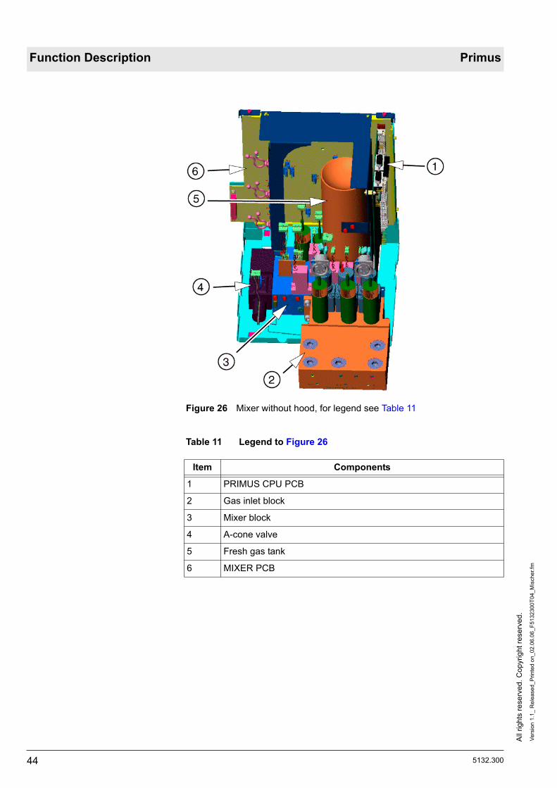
Figure 26 Mixer without hood, for legend see Table 11
Table 11 Legend to Figure 26
Item Components
1 PRIMUS CPU PCB
2 Gas inlet block
3 Mixer block
4 A-cone valve
5 Fresh gas tank
6 MIXER PCB

5132.300
All
right
s re
serv
ed. C
opyr
ight
rese
rved
.Ve
rsio
n 1.
1_ R
elea
sed_
Prin
ted
on_0
2.06
.06_
F513
2300
T04_
Mis
cher
.fm
45
Primus Function Description
Figure 27 Block diagram of fresh gas metering, legend Table 12
Table 12 Legend to Figure 27
The item numbers and abbreviations occurring in this section relate to Figure 27 .
On the MCP (1) the user selects the carrier gas AIR or N2O as well as the fresh gas flow and the O2 concentration.
A CAN bus (2) transfers the setup parameters to the mixer electronics (3). The mixer electronics generate the actuation signals for the gas inlet valves (7).
At the inlet of the fresh gas tank (6) the flow (V) is measured. With the mea-sured flow value the switching times for the gas inlet valves (7) are calcu-lated. The selected gas concentration is set in the fresh gas tank. The pressure in the tank (6) and at the fresh gas outlet (4) is measured and moni-tored.
Item Component
1 Monitor Control Panel (MCP)
2 CAN bus
3 Mixer electronics (PRIMUS CPU PCB/MIXER PCB)
4 Fresh gas outlet
5 Fresh gas flow valve
6 Fresh gas tank
7 Gas inlet valves
8 Pressure regulator

All
right
s re
serv
ed. C
opyr
ight
rese
rved
.Ve
rsio
n 1.
1_ R
elea
sed_
Prin
ted
on_0
2.06
.06_
F513
2300
T04_
Mis
cher
.fm
46 5132.300
Function Description Primus
The fresh gas flow valve (5) delivers the selected fresh gas flow. The flowme-ter at the fresh gas outlet (4) regulates the fresh gas flow valve.
5.1 Operating modes The operating mode is regardless of whether the Primus is powered from the mains via its power plug or is powered up in battery mode.
5.1.1 10 VA mode Internal leakage may mean that the O2 concentration in the Primus is above 21% when operation is begun. “10 VA” mode prevents dangerous operating states from occurring.
When the power plug is connected to the mains power but the power switch is not yet switched on, the following safety rule applies:– A supply voltage of only 10 VA is fed into the interior of the mixer (10 VA
is the product of the no-load voltage and short-circuit current of the supply voltage “24 V PLUG-IN”. Only the DC/DC converters (-15 V, +15 V) for the pressure sensor amplifiers are supplied).
– The pressure sensors for the gases from the central supply (CS) system and the cylinder supply are read and the compressed gas supply status is indicated by LEDs on the front panel (see 5.3.2 Pressure status LEDs).
When the Primus is switched on at the power switch (mains or battery pow-ered) the following safety rule applies:– Before other modules receive operating voltage, the fan in the mixer is
switched on for at least 10 seconds. Only then is “Normal” mode acti-vated.
5.1.2 'Normal' mode In this mode the mixer CPU PCB controls normal mixing. All DC/DC convert-ers (+5 V, +24 V, -15 V, +15 V) are supplied with “24 V SWITCH”.
5.2 Layout
5.2.1 MIXER PCB In the “Block diagrams” section you will find a block diagram of the MIXER PCB.
The MIXER PCB holds the following components:– DC/DC converters (+5 V, + 15 V, - 15 V, +24 V) with voltage monitoring– Amplifiers of the pressure and temperature sensors– Valve power switch and monitoring circuits – Fan actuation and monitoring– Logic device for the safety O2 adjuster
A cable harness connects the mixer with the NEUTRAL POINT PCB and with the other unit components. By way of the cable harness the mixer receives the unstabilized 18 V to 30 V supply voltage and the 12 V fan power from the power pack as well as the CAN bus.
The mixer fan is switched on 10 seconds before the other components and is powered directly by the power pack (see 5.1.1 10 VA mode).
When the fan wheel rotates a proportional square signal is generated (approx. 90 Hz). This square signal is monitored by the PRIMUS CPU PCB.
5132.300
All
right
s re
serv
ed. C
opyr
ight
rese
rved
.Ve
rsio
n 1.
1_ R
elea
sed_
Prin
ted
on_0
2.06
.06_
F513
2300
T04_
Mis
cher
.fm
47
Primus Function Description
The valves on the mixer block are actuated by the Master CPU (PRIMUS CPU PCB). Power drivers on the MIXER PCB operate the valves. When one of the valves is actuated, the current flows through a shunt. The voltage drop at the shunt is evaluated by a comparator circuit and monitored by the super-visor processor on the PRIMUS CPU PCB. An exception to this is the fresh gas flow valve “VMGS”. The proportional valve cannot be monitored by this procedure.
For safety shut-off of all valves, the supply voltage can be cut to all valves.
5.2.2 PRIMUS CPU PCB (mixer)
In the “Block diagrams” section you will find a block diagram of the PRIMUS CPU PCB.
The PRIMUS CPU PCB is based on a 2-processor system with Master and Supervisor. Both 16-bit processor systems are identical in structure. The peripherals are controlled by way of an interface.
Each processor has the following components:– Quartz– undervoltage detector– External watchdog– Flash-PROM– RAM– EEPROM (system configuration)
A Dual-Port RAM is placed between the two processor systems for data exchange. A logic circuit prevents both processors writing to a memory cell simultaneously.
Each processor system has an isolated serial port and a CAN bus.
Configuration options for the serial port by jumper:– Independent serial ports, RS232 level, isolation on jack plug.– Independent serial ports, TTL level, no isolation, output to connector strip.
7-segment displays are provided for visual indication of operating states of the Master and the Supervisor.

All
right
s re
serv
ed. C
opyr
ight
rese
rved
.Ve
rsio
n 1.
1_ R
elea
sed_
Prin
ted
on_0
2.06
.06_
F513
2300
T04_
Mis
cher
.fm
48 5132.300
Function Description Primus
5.3 Gas inlet block (AIR, O2 and N2O)
In the “Block diagrams” section you will find a detailed layout of the pneumatic components of the Primus.
On the underside of the gas inlet block are the ISO ports for the CS gases (Figure 28/1) e.g. Nist or DISS and the compressed gas cylinder ports for N2O and O2 (Figure 28/2).
Figure 28 CS/compressed gas cylinder ports
Optional outlets for a bronchial suction device with AIR (Figure 29/1) and for a O2 flowmeter (Figure 29/2) are prepared.
Figure 29 Optional outlets AIR (1) and O2 (2)
The following specifications apply to the CS and the compressed gas cylin-ders:– The pressure values of the CS gases must be between 270 kPa and
690 kPa (19 psi to 80 psi).

5132.300
All
right
s re
serv
ed. C
opyr
ight
rese
rved
.Ve
rsio
n 1.
1_ R
elea
sed_
Prin
ted
on_0
2.06
.06_
F513
2300
T04_
Mis
cher
.fm
49
Primus Function Description
– If the CS pressure falls below 270 kPa, the user must open the O2 or N2O compressed gas cylinder, as appropriate. If the cylinder pressure is too low, the user is warned on the MCP display. The maximum cylinder pressure is 19000 kPa.
Figure 30 Detail, gas inlet block, for legend see Table 13
Table 13 Legend to Figure 30
Item Component
1 Pressure regulators (N2O, AIR, O2) regulate the input pressure to the mixer to 2.3 0.1 bar
2 Sintered-metal filter
3 ISO port (e.g. NIST for O2 cylinder supply)
4 Optional gas outlet (plug-in connection for AIR)
5 Non-return valve
6 Non-return valve for N2O gas inlet
7 CS sensor N2O
8 CS sensor AIR
9 CS sensor O2

All
right
s re
serv
ed. C
opyr
ight
rese
rved
.Ve
rsio
n 1.
1_ R
elea
sed_
Prin
ted
on_0
2.06
.06_
F513
2300
T04_
Mis
cher
.fm
50 5132.300
Function Description Primus
5.3.1 Pneumatic components, gas inlet block
Figure 31 Pneumatic components diagram, gas inlet block, for legend see Table 14
Table 14 Legend to Figure 31
Abb./Item Component
PPO2 Relative pressure sensors with integral amplifier for CS pressure measurementPPAIR
PPN2O
PCO2 High-pressure sensor cylinder pressure O2
PCN2O High-pressure sensor cylinder pressure N2O
PRPO2 Pressure regulator, O2 line
PRPAIR Pressure regulator, AIR line
PRPN2O Pressure regulator, N2O line
PRCO2 Pressure regulator, O2 compressed gas cylinder

5132.300
All
right
s re
serv
ed. C
opyr
ight
rese
rved
.Ve
rsio
n 1.
1_ R
elea
sed_
Prin
ted
on_0
2.06
.06_
F513
2300
T04_
Mis
cher
.fm
51
Primus Function Description
The item numbers and abbreviations occurring in this section relate to Figure 31 .
For the following description the O2 gas path was chosen.
The CS gas (3) passes through the ISO port to the gas inlet block.
By way of the sintered-metal filter (4) the gas passes to the pressure sensor “PPO2”. The relative pressure sensor delivers a signal proportional to the pressure.
The sintered-metal filter (4) prevents the non-return valve (5) from being con-taminated by particles.
If the CS fails, no CS pressure is indicated. The non-return valve (5) prevents O2 from escaping out of the compressed gas cylinder (2) into the CS system.
The pressure regulator PRPO2 generates a constant input pressure for the mixer (2.3 bar 0.1 bar). The O2 pressure regulator additionally supplies (8) the flush button “VO2+” and the safety O2 adjuster “VSFC”.
An optional compressed gas supply for an external bronchial suction device (7) or an external O2 flowmeter (6) is provided for.
PRCN2O Pressure regulator, N2O compressed gas cylinder
1 Gas inlet block (complete)
2 HP ISO port O2 (NIST or DISS)
3 CS ISO port O2 (NIST or DISS)
4 Sintered-metal filter in CS ISO port
5 Non-return valve, CS inlet O2
6 ISO outlet O2 (optional)
7 ISO outlet AIR (optional)
8 To flush button and safety O2 adjuster
9 To the CS flow metering inlet valves
Abb./Item Component
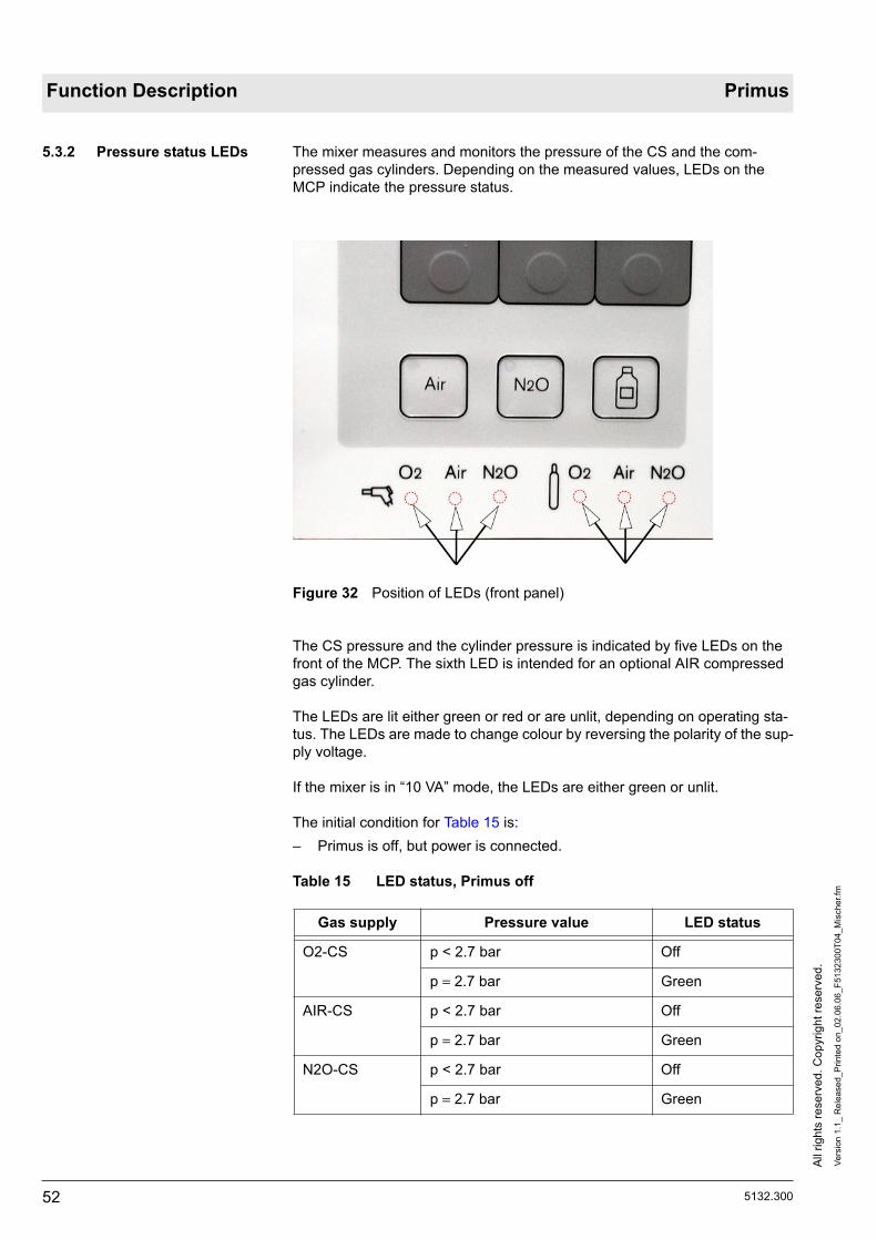
All
right
s re
serv
ed. C
opyr
ight
rese
rved
.Ve
rsio
n 1.
1_ R
elea
sed_
Prin
ted
on_0
2.06
.06_
F513
2300
T04_
Mis
cher
.fm
52 5132.300
Function Description Primus
5.3.2 Pressure status LEDs The mixer measures and monitors the pressure of the CS and the com-pressed gas cylinders. Depending on the measured values, LEDs on the MCP indicate the pressure status.
Figure 32 Position of LEDs (front panel)
The CS pressure and the cylinder pressure is indicated by five LEDs on the front of the MCP. The sixth LED is intended for an optional AIR compressed gas cylinder.
The LEDs are lit either green or red or are unlit, depending on operating sta-tus. The LEDs are made to change colour by reversing the polarity of the sup-ply voltage.
If the mixer is in “10 VA” mode, the LEDs are either green or unlit.
The initial condition for Table 15 is:– Primus is off, but power is connected.
Table 15 LED status, Primus off
Gas supply Pressure value LED status
O2-CS p < 2.7 bar Off
p 2.7 bar Green
AIR-CS p < 2.7 bar Off
p 2.7 bar Green
N2O-CS p < 2.7 bar Off
p 2.7 bar Green

5132.300
All
right
s re
serv
ed. C
opyr
ight
rese
rved
.Ve
rsio
n 1.
1_ R
elea
sed_
Prin
ted
on_0
2.06
.06_
F513
2300
T04_
Mis
cher
.fm
53
Primus Function Description
The initial condition for Table 16 is:– Primus is on. The mixer is in normal mode.
Table 16 LED status, Primus in normal mode
O2 cylinder p < 20 bar Off
p 20 bar Green
Pressure sensor not connected Off
AIR cylinder p < 20 bar Off
p 20 bar Green
Pressure sensor not connected Off
N2O cylinder p < 10 bar Off
p 10 bar Green
Pressure sensor not connected Off
Gas supply Pressure value LED status
O2-CS p < 2.7 bar Off
p 2.7 bar Green
Pressure sensor error Flashing green
AIR-CS p < 2.7 bar Off
p 2.7 bar Green
Error Flashing
N2O-CS p < 2.7 bar Off
p 2.7 bar Green
Pressure sensor error Flashing green
O2 cylinder p < 20 bar and CS O2 pressure is 2.7 bar
Off
p 20 bar Green
p < 20 bar and the CS O2 pres-sure is < 2.7 bar
Flashing red at 1.4 to 2.8 Hz
Pressure sensor not connected Off
AIR cylinder p < 10 bar and the CS N2O pressure is < 2.7 bar
Flashing red at 1.4 to 2.8 Hz
p 10 bar Green
Pressure sensor not connected Off
p < 10 bar and CS N2O pres-sure is 2.7 bar
Off
Gas supply Pressure value LED status

All
right
s re
serv
ed. C
opyr
ight
rese
rved
.Ve
rsio
n 1.
1_ R
elea
sed_
Prin
ted
on_0
2.06
.06_
F513
2300
T04_
Mis
cher
.fm
54 5132.300
Function Description Primus
N2O cylinder p < 10 bar and CS N2O pres-sure is 2.7 bar
Off
p 10 bar Green
p < 10 bar and CS N2O pres-sure is < 2.7 bar
Flashing red at 1.4 to 2.8 Hz
Pressure sensor not connected Off
Gas supply Pressure value LED status

5132.300
All
right
s re
serv
ed. C
opyr
ight
rese
rved
.Ve
rsio
n 1.
1_ R
elea
sed_
Prin
ted
on_0
2.06
.06_
F513
2300
T04_
Mis
cher
.fm
55
Primus Function Description
5.4 Mixer block
Figure 33 Mixer block, for legend see Table 17
Table 17 Legend to Figure 33
Item Component Short name
1 Differential pressure sensors with piezo mea-suring bridge
PDMGSHI
2 PDMGSLO
3 Absolute pressure sensors with integral ampli-fier
PSYS
4 PTANK
5 Tank vent valve VTANK
6 Temperature sensors TANKTEMP, MGSTEMP
7 Connection for tank volume TANK
8 Gas inlet valves VMIXO2
9 VMIXAIR
10 VMIXN2O
11 Pressure inlets (N2O, AIR, O2) to the gas inlet valves
12 O2 inlet to safety O2 adjuster and flush button
13 Differential pressure sensor with piezo measur-ing bridge
PDMIX
14 Fresh gas flow valve (proportional valve) VMGS
15 A-cone valve VSWAK

All
right
s re
serv
ed. C
opyr
ight
rese
rved
.Ve
rsio
n 1.
1_ R
elea
sed_
Prin
ted
on_0
2.06
.06_
F513
2300
T04_
Mis
cher
.fm
56 5132.300
Function Description Primus
5.5 Pneumatic system
Figure 34 Pneumatic components diagram, mixer, for legend see Table 18
Table 18 Legend to Figure 34
In the “Block diagrams” section you will find a detailed layout of the pneumatic components of the Primus.
The abbreviations occurring in the following sections relate to Figure 34 and Figure 33.
Item Component/Meaning
1 Gas inlet block
2 A-cone valve (optional)
3 Mixer, flow metering
4 Vaporizer
I To compact breathing system
II To A-cone valve/compact breathing system switching valve (MV3) for airway pressure measurement
III To A-cone outlet

5132.300
All
right
s re
serv
ed. C
opyr
ight
rese
rved
.Ve
rsio
n 1.
1_ R
elea
sed_
Prin
ted
on_0
2.06
.06_
F513
2300
T04_
Mis
cher
.fm
57
Primus Function Description
5.5.1 VMIX valves The “VMIX” valves mix the desired gas concentration. By way of the “VMIX” valves the CS gas (N2O, AIR, O2) passes to the differential pressure sensor “PDMIX”, to the pressure sensor “PTANK” and to the flowmeter section “RM”.
The “VMIX” valves fill “TANK”. The pressure range in 'TANK“ is between 1 bar and 1.5 bar. The pressure difference of 0.5 bar and the “TANK” volume of 0.5 L produce a usable “TANK” volume of 0.25 L (0.5 bar x 0.5 L = 0.25 L).
At a fresh gas flow setting of 18 L/min, the “VMIX” valves are opened 72 times a minute. The following equation illustrates the TANK filling process (72 /min x 0.25 L = 18 L/min).
5.5.2 PDMIX and RM With the differential pressure sensor “PDMIX” and the flowmeter “RM” the gas flow and volume of the gas flowing into the TANK are measured (flow x time = volume). If a constant usable 'TANK' volume of 0.25 L is used then any given gas concentration can be mixed.
The differential pressure sensor “PDMIX” and the absolute pressure sensor “PTANK” form a single functional unit. The output signal of the pressure sen-sor “PTANK” is used for the bridge supply voltage for “PDMIX”. The output voltage of “PDMIX” is evaluated on the PRIMUS CPU PCB (mixer).
5.5.3 PTANK (pressure sen-sor)
The pressure sensor “PTANK” has the following tasks:– Tank pressure monitoring– Compensation for effect of ambient pressure fluctuations on flow meter-
ing with “PDMIX”.– Monitoring of flowmeter “RM” by means of the proportional pressure rise
in “TANK”.
The pressure sensor “PTANK” has a resolution of 2 mbar and a maximum measuring range of 2.558 bar absolute. The pressure sensor “PTANK” also has a second amplification branch to the AD converter of the PRIMUS CPU PCB (mixer). To be able to measure higher pressures for service purposes, the resolution is 4 mbar per digit. The maximum measured value is 4.092 bar absolute.
5.5.4 VTANK valve The tank vent valve “VTANK” opens when:– O2 and AIR are missing.
5.5.5 VMGS (fresh gas flow valve)
The fresh gas flow valve is a proportional valve. It delivers a fresh gas flow of 0.2 L/min to 18 L/min. The flowmeter at the fresh gas outlet regulates the valve.
5.5.6 PDMGSHI / PDMGSLO (differential pressure sensors)
The differential pressure sensors each have a press-dependent resistance measuring bridge.
The differential pressure sensors measure the flow through the flowmeter section “RMGS”. With the measured value the PRIMUS CPU (mixer) PCB regulates the fresh gas flow valve “VMGS”.
5.5.7 PSYS (pressure sensor) The pressure sensor “PSYS” compensates for the effect of ambient pressure fluctuations on the flow metering of “PDMGSHI” and “PDMGSLO”.
The pressure sensor “PSYS” has a resolution of 1 mbar.
All
right
s re
serv
ed. C
opyr
ight
rese
rved
.Ve
rsio
n 1.
1_ R
elea
sed_
Prin
ted
on_0
2.06
.06_
F513
2300
T04_
Mis
cher
.fm
58 5132.300
Function Description Primus
5.5.8 VSWAK (A-cone valve) The A-cone valve actuated by the MIXER PCB has a bistable switching response.
The valve is switched with a time-limited voltage pulse. The polarity of the voltage pulse determines the switching direction.
The valve position is detected by a proximity sensor in the valve and moni-tored by the PRIMUS CPU (mixer) PCB.
5.5.9 VBAK (safety valve) A mechanical safety valve for the A-cone valve. Opening pressure 80 mbar at 18 L/min +15%.
5.5.10 TEMPTANK / TEMP-BLOCK (temperature sensors)
The volume of the gases “N2O, AIR, O2” is dependent on the temperature. Consequently, the measured values of the temperature sensors “NTC” are incorporated into the mixing process. The temperature sensors (“TEMP-TANK”, “TEMPBLOCK”) used for temperature compensation generate volt-ages proportional to the temperature. The PRIMUS CPU (mixer) PCB compares and monitors the sensor voltages.
5.5.11 VSFC (safety O2 adjuster)
The safety O2 adjuster is located outside the mixer unit. With the manual safety O2 adjuster the user can set an additional O2 flow of 3 to 12 L/min 30%.
When the overall system power-up test is running the flow adjuster must be closed. The operating status is registered by a microswitch in the safety O2 adjuster. The microswitch is plugged into the NEUTRAL POINT PCB. The signal is transmitted via the cable harness to the mixer.
5.5.12 VO2+ (flush button) Mechanical flush button. Output min. 35 L/min.
The function description relating to the VGC follows.

5132.300
All
right
s re
serv
ed. C
opyr
ight
rese
rved
.Ve
rsio
n 4.
0_ R
elea
sed_
Prin
ted
on_0
2.06
.06_
F513
2300
T05_
VG
C.fm
59
Primus Function Description
6 VGC This section describes the VGC (Ventilation and Gas Controller). The VGC consists of the ventilator and the compact breathing system.
Figure 35 VGC position
The patient is ventilated by the VGC according to the ventilation mode and parameters set on the MCP.
The VGC also measures the airway pressure and the inspiratory and expira-tory flow (two flow sensors).
A cable harness connects the VGC with the NEUTRAL POINT PCB. From there, the VGC is connected to other Primus components.
By way of the cable harness the VGC receives the following voltages and sig-nals:– The unstabilized supply voltage of 18 V to 30 V.– The 12 V for the VGC fan (there immediately).– The 12 V for the pneutronics valves (there after approx. 10 seconds).– CAN bus.

All
right
s re
serv
ed. C
opyr
ight
rese
rved
.Ve
rsio
n 4.
0_ R
elea
sed_
Prin
ted
on_0
2.06
.06_
F513
2300
T05_
VG
C.fm
60 5132.300
Function Description Primus
Figure 36 Exploded view of VGC, legend Table 19
Table 19 Legend to Figure 36
Item Component
1 MV4 “Pneutronics”
2 MV2, calibration and venting
3 Electrical connections for inspiratory and expiratory flow sensor
4 Piston-cylinder unit.
5 VGC POWER PCB.
6 CPU PRIMUS PCB.
7 Electronics fan.
8 PRIMUS ANALOG PCB (VGC).

5132.300
All
right
s re
serv
ed. C
opyr
ight
rese
rved
.Ve
rsio
n 4.
0_ R
elea
sed_
Prin
ted
on_0
2.06
.06_
F513
2300
T05_
VG
C.fm
61
Primus Function Description
6.1 VGC electronics In the “Block diagrams” section, you will find a block diagram of the VGC electronics.
The supply voltages required for the VGC to function (5 V, 15 V, +24 V) are generated by the VGC itself.
The interface plate holds the connecting pneumatic tubes and the plug-in flow sensor connectors.
The interface plate is the carrier for all other VGC components, and includes the breathing system lock. The complete interface unit is inserted from above into the VGC housing.
6.1.1 VGC POWER PCB The following functional units are provided on the PCB:– 5 V voltage regulator (Imax 2 A).– Driver for the DC motor (M2) of the piston cylinder unit (PCU).– Valve control.– Breathing system heater control. Temperature monitoring with 2 indepen-
dent NTCs in the heater mat.– Control for the DC pump (M1). Output voltage 8 to 18 V.– Monitoring of the PCB supply voltages.
6.1.2 PRIMUS ANALOG PCB The following functional units are provided on the PCB:– +15 V voltage regulator (Imax 300 mA). 15 V is only connected if 5 V is
present.– -15 V voltage regulator (Imax ca. 100 mA).– PEEP valve control (0 to 430 mA).– Pressure measurement with two airway pressure sensors and a vacuum
sensor.– 12-bit A/D converter for the airway pressure sensors and the flow sen-
sors.– Incremental encoder evaluation. Evaluation of direction of rotation, rota-
tion angle and velocity of the PCU motor (M2).– Light barriers. One light barrier each for the end position of the PCU and
for detection of a fully inserted ventilator drawer unit.
9 Bacterial filter.
10 Non-return valve RV3.
11 VGC pneumatic block.
12 Interface plate.
13 Interface plate fan.
14 Light barrier.
15 Breathing system heater contacts.
Item Component

All
right
s re
serv
ed. C
opyr
ight
rese
rved
.Ve
rsio
n 4.
0_ R
elea
sed_
Prin
ted
on_0
2.06
.06_
F513
2300
T05_
VG
C.fm
62 5132.300
Function Description Primus
6.2 Piston cylinder unit (PCU)
Figure 37 Piston cylinder unit layout, for legend see Table 20
Table 20 Legend to Figure 37
Item Component
1 Breathing volume dependent on piston position.
2 Cylinder.
3 Rolling seal (loose).
4 Piston.
5 Diaphragm (fixed).
6 Piston motor.
7 Perforated disk for incremental encoder.
8 incremental encoder.
9 Rubber buffer.
10 Light barrier.
11 Spindle nut.
12 Spindle.

5132.300
All
right
s re
serv
ed. C
opyr
ight
rese
rved
.Ve
rsio
n 4.
0_ R
elea
sed_
Prin
ted
on_0
2.06
.06_
F513
2300
T05_
VG
C.fm
63
Primus Function Description
The items cited in the following text relate to Figure 37.
The ventilator unit consists of a piston cylinder unit and two diaphragms. The vacuum for the rolling seal (3) comes from the pneumatic system of the VGC and is generated in the space between the cylinder (2) and the rolling seal (3).
The spindle (12) is permanently fixed to the piston. The spindle nut (11) is permanently fixed to the hollow shaft axle of the piston motor. When the motor shaft, and thus the spindle nut, rotates the spindle is moved vertically. This sends a corresponding volume through to the compact breathing system and consequently to the patient. Also, the motor is permanently fixed with rubber buffers (9) to the drive housing.
When the spindle nut rotates once, a volume displacement of 38.5 mL is pro-duced. So to achieve a volume change of 1400 mL, around 37 revolutions are required.
The piston motor (6) is powered by direct voltage and operated by way of the PCBs of the VGC. The actuator requires the signal from the incremental encoder (8). The incremental encoder has a resolution of 1024 pulses per motor revolution.
When the VGC is switched on, the counter of the incremental encoder must be set. To do so, the piston is lowered until it reaches the light barrier (10). This position is then recorded as the reference position.
Only when the vacuum is applied to the rolling seal is the piston motor acti-vated. An exception is possible, however. If the roller diaphragm is not inserted, a vacuum may be created. The roller diaphragm can only be inserted without difficulty when the piston is at its bottom end position, how-ever. If the control detects this state, it will slowly move the piston to the bot-tom end position in “Standby” mode. With software version 2.n or higher, the piston motor (6) is additionally switched on as an active brake as soon as the light barrier (10) is touched. This is to avoid that the spindle (12) gets stuck in the bottom end position.

All
right
s re
serv
ed. C
opyr
ight
rese
rved
.Ve
rsio
n 4.
0_ R
elea
sed_
Prin
ted
on_0
2.06
.06_
F513
2300
T05_
VG
C.fm
64 5132.300
Function Description Primus
6.3 VGC pneumatic block
Figure 38 Exploded view of VGC pneumatic system, legend Table 21
Table 21 Legend to Figure 38
The components of the pneumatic block are detailed in the following section.
Item Components
1 PEEP valve “MV1”.
2 Restrictor “R2”.
3 Pump motor “M2” with vacuum pump “VP”.
4 Vacuum valve “Vu”.
5 Bacterial filter “BF”.
6 Volume “V” (2 containers).
7 Solenoid valve “MV3”“Pneutronics”.

5132.300
All
right
s re
serv
ed. C
opyr
ight
rese
rved
.Ve
rsio
n 4.
0_ R
elea
sed_
Prin
ted
on_0
2.06
.06_
F513
2300
T05_
VG
C.fm
65
Primus Function Description
6.4 VGC pneumatic sys-tem
In the “Block diagrams” section, you will find a detailed schematic of the Pri-mus pneumatic components.
Figure 39 VGC pneumatic system and breathing system, for legend see Table 22
Table 22 Legend to Figure 39
Item Component/Meaning
5 VGC ventilator unit.
6 Breathing system.
I Fresh gas inlet.
II From A-cone valve (if fitted).
E Ejector.
BF Bacterial filter.
M2 Vacuum pump motor.
MV1 PEEP/Pmax valve.
MV2 Calibration and vent valve.
MV3 Breathing system/A-cone outlet switching valve.
MV4 PEEP valve/control valve.

All
right
s re
serv
ed. C
opyr
ight
rese
rved
.Ve
rsio
n 4.
0_ R
elea
sed_
Prin
ted
on_0
2.06
.06_
F513
2300
T05_
VG
C.fm
66 5132.300
Function Description Primus
The position numbers mentioned in this section refer to Figure 39.
The vacuum sensor “Pu” is connected to the intake side of the vacuum pump “VP”. In operation, the vacuum sensor “Pu” measures the vacuum for the roller diaphragm of the KZE. Another port is connected during operation to the switching valve “V2”“AUTO-MAN/SPONT”. When the vacuum pump is running, the software checks the pressure value at the vacuum sensor “Pu”. The drive motor is only activated if the vacuum pump is able to build up a vac-uum of between 120 mbar and 250 mbar (hPA).
The vacuum pump “VP” draws the air in through the bacterial filter “BF”. The following valve “Vu” is preset to approx. 200 mbar. The air is pumped in two consecutive volumes “V”.
To smooth pressure peaks, the outlet of the volumes is designed as a fine hole “R1”. From there, the gas flows through the PEEP valve “MV1”. If the PEEP valve is not actuated, the integral ejector “E” generates a low-level vac-uum in its control line. This smoothes the zero of the PEEP characteristic.
So that the vacuum is reduced when the vacuum pump is shut off, the vac-uum valve is bridged by a restrictor “R2”.
When the user switches the ventilation mode from automatic ventilation to “MAN/SPONT”, the vacuum pump is switched off. The vacuum is reduced with “R2”. The non-return valve “RV3” prevents the vacuum in the diaphragm volume from being reduced too. This considerably reduces the switching time from automatic ventilation to “MAN/SPONT”. At the same time, “RV3” also prevents a reduction of the vacuum in the diaphragm volume in “MAN/SPONT” mode. The vacuum can then be built up faster when the user switches to an automatic ventilation mode.
With valve “MV2” the system is calibrated and vented.
PAWe Expiratory airway pressure sensor.
Pu Vacuum sensor.
R1 Restrictor to smooth pressure peaks.
R2 Restrictor to reduce vacuum (when pump “VP” is off).
RV3 KZE vacuum non-return valve.
V Volume.
VP Vacuum pump.
Item Component/Meaning

5132.300
All
right
s re
serv
ed. C
opyr
ight
rese
rved
.Ve
rsio
n 4.
0_ R
elea
sed_
Prin
ted
on_0
2.06
.06_
F513
2300
T05_
VG
C.fm
67
Primus Function Description
6.5 Interface plate
Figure 40 Layout of interface plate measuring points, for legend see Table 23
Table 23 Legend to Figure 40 and Figure 41
Item Connection/Meaning
1 Pressure sensor “Pz”.
2 Fresh gas outlet.
3 Anesthetic gas scavenging system AGSS.
4 ILCA suction device (optional).
5 PEEP valve “V1”.
6 APL bypass valve “V2”.
7 “PAWe” / “MV2”.
8 ILCA sampling gas return line (optional).
9 Expiratory flow sensor (electric).
10 IRIA sampling gas return line.
11 Inspiratory flow sensor (electrical).
12 A-cone airway pressure.
13 IRIA sampling gas return line.
14 Fresh gas.

All
right
s re
serv
ed. C
opyr
ight
rese
rved
.Ve
rsio
n 4.
0_ R
elea
sed_
Prin
ted
on_0
2.06
.06_
F513
2300
T05_
VG
C.fm
68 5132.300
Function Description Primus
The following diagram Figure 41 permits allocation of the measuring points/connections on the interface plate to the pneumatic components dia-gram.
Figure 41 Allocation of measuring points/connections, for legend see Table 23
15 Piston of piston cylinder unit.
Item Connection/Meaning

5132.300
All
right
s re
serv
ed. C
opyr
ight
rese
rved
.Ve
rsio
n 4.
0_ R
elea
sed_
Prin
ted
on_0
2.06
.06_
F513
2300
T05_
VG
C.fm
69
Primus Function Description
6.6 Breathing system There can be two different types of breathing systems. The difference lies in the design of the APL valve (adjustable pressure-limiting valve, see Figure 42).
Figure 42 APL valves, new type (1) and old type (2)
The new type (Figure 42/2) has a toggle mechanism for toggling between MAN and SPONT mode. The new type (Figure 42/1) uses a locking function.
This results in different types of breathing system covers (see breathing sys-tem cover Figure 43/1). The valve plate (Figure 43/5) and the breathing sys-tem block (Figure 43/6) remain unchanged.

All
right
s re
serv
ed. C
opyr
ight
rese
rved
.Ve
rsio
n 4.
0_ R
elea
sed_
Prin
ted
on_0
2.06
.06_
F513
2300
T05_
VG
C.fm
70 5132.300
Function Description Primus
Figure 43 Overview of the breathing system, see legend Table 24
Table 24 Legend to Figure 43
Item Component
1 Breathing system cover with fixing screws.
2 Valve “RV1”.
3 Breathing system heater contacts.
4 Valve “RV2” (new design).
5 Valve plate.
6 Breathing system block.

5132.300
All
right
s re
serv
ed. C
opyr
ight
rese
rved
.Ve
rsio
n 4.
0_ R
elea
sed_
Prin
ted
on_0
2.06
.06_
F513
2300
T05_
VG
C.fm
71
Primus Function Description
The compact breathing system permits the following ventilation modes:– Manual ventilation.– Spontaneous breathing.– Automatic, pressure-limited ventilation modes (IPPV, SIMV and PCB) or
“Volume Mode” and “Pressure Mode” with optional synchronization and pressure support.
– (Optional) pressure-assisted ventilation “Pressure Support” for spontane-ously breathing patients.
The switch of the APL valve can be set to MAN or SPONT.
In the “MAN” position, the breathing system is closed to atmosphere. The APL valve opening pressure can be adjusted from 5 to 70 hPa (mbar). This switch setting is the default for manual ventilation.
In the “SPONT” position the APL valve is open to atmosphere. This switch setting is the default for spontaneous breathing.
The pressure limitation “Pmax” can also be adjusted between 20 hPa (mbar) and 70 hPa (mbar) on the GUI during automatic ventilation.
The following section permits allocation of the components to the pneumatic components diagram.
7 Fixing screws.
8 Absorber canister.
9 Absorber element.
10 Expiratory flow sensor “Flowe”.
11 Connection for manual breathing bag “Bag”.
12 Expiratory socket.
13 Inspiratory socket with downstream inspiratory flow sensor “Flowi”.
14 APL bypass valve “V2”.
15 Valve “V1”, PEEP diaphragm.
16 Expiratory valve “Ve”.
17 Inspiratory valve “Vi”.
18 “APL” valve, new type.
19 “APL” valve, old type.
Item Component

All
right
s re
serv
ed. C
opyr
ight
rese
rved
.Ve
rsio
n 4.
0_ R
elea
sed_
Prin
ted
on_0
2.06
.06_
F513
2300
T05_
VG
C.fm
72 5132.300
Function Description Primus
6.6.1 Compact breathing sys-tem pneumatic compo-nents
In the “Block diagrams” section, you will find a detailed schematic of the Pri-mus pneumatic components.
Figure 44 Breathing system and VGC pneumatic components, for legend see Table 25
Table 25 Legend to Figure 44
Item / Abbrevia-tion
Component
6 Breathing system pneumatic components.
A Absorber
V2 APL bypass valve.
APL APL valve.
Ve Expiratory valve.
PAWe Expiratory pressure sensor.
FLOWe Expiratory flow sensor.
FG Fresh-gas port.
RV1 Fresh-gas decoupling valve.
BAG Breathing bag.
Vi Inspiratory valve.
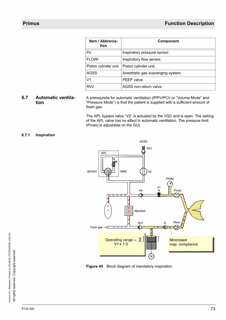
5132.300
All
right
s re
serv
ed. C
opyr
ight
rese
rved
.Ve
rsio
n 4.
0_ R
elea
sed_
Prin
ted
on_0
2.06
.06_
F513
2300
T05_
VG
C.fm
73
Primus Function Description
6.7 Automatic ventila-tion
A prerequisite for automatic ventilation (IPPV/PCV or “Volume Mode” and “Pressure Mode”) is that the patient is supplied with a sufficient amount of fresh gas.
The APL bypass valve “V2” is actuated by the VGC and is open. The setting of the APL valve has no effect in automatic ventilation. The pressure limit (Pmax) is adjustable on the GUI.
6.7.1 Inspiration
Figure 45 Block diagram of mandatory inspiration
Pz Inspiratory pressure sensor.
FLOWi Inspiratory flow sensor.
Piston cylinder unit Piston cylinder unit.
AGSS Anesthetic gas scavenging system.
V1 PEEP valve.
RV2 AGSS non-return valve.
Item / Abbrevia-tion
Component

All
right
s re
serv
ed. C
opyr
ight
rese
rved
.Ve
rsio
n 4.
0_ R
elea
sed_
Prin
ted
on_0
2.06
.06_
F513
2300
T05_
VG
C.fm
74 5132.300
Function Description Primus
The abbreviations occurring in the following text relate to Figure 45 .
Mandatory inspiration process:– The fresh gas isolation valve “RV1” is closed.– The PEEP valve “V1” is closed during inspiration. Depending on the pre-
set maximum pressure “Pmax”, an appropriate control pressure is applied to the PEEP valve.
– The piston of the PCU rises according to the preset parameters (F, VT, I:E...). The mixed gas (expiratory gas and fresh gas) flows through the inspiratory valve “Vi”, the flow sensor “Flowi”, the inspiratory patient tube, and through the Y-piece into the patient’s lung.
– The inspiratory pressure is measured.– For inspiratory compliance only the volume between “RV1”, “Vi” and “V1”
is active.– The manual breathing bag serves as a mixed gas reservoir.
If the ventilation pressure exceeds the maximum pressure (Pmax) set on the GUI, the PEEP “V1” opens. The gas from the patient's lung flows either into the manual breathing bag or through the open APL bypass valve “V2”. Depending on the non-return valve opening pressure “RV2”, the mixed gas flows into the anesthetic gas scavenging system AGSS.
Advantage of this method:– The fresh gas isolation valve “RV1” minimizes the inspiratory compliance
(without absorber and manual breathing bag).
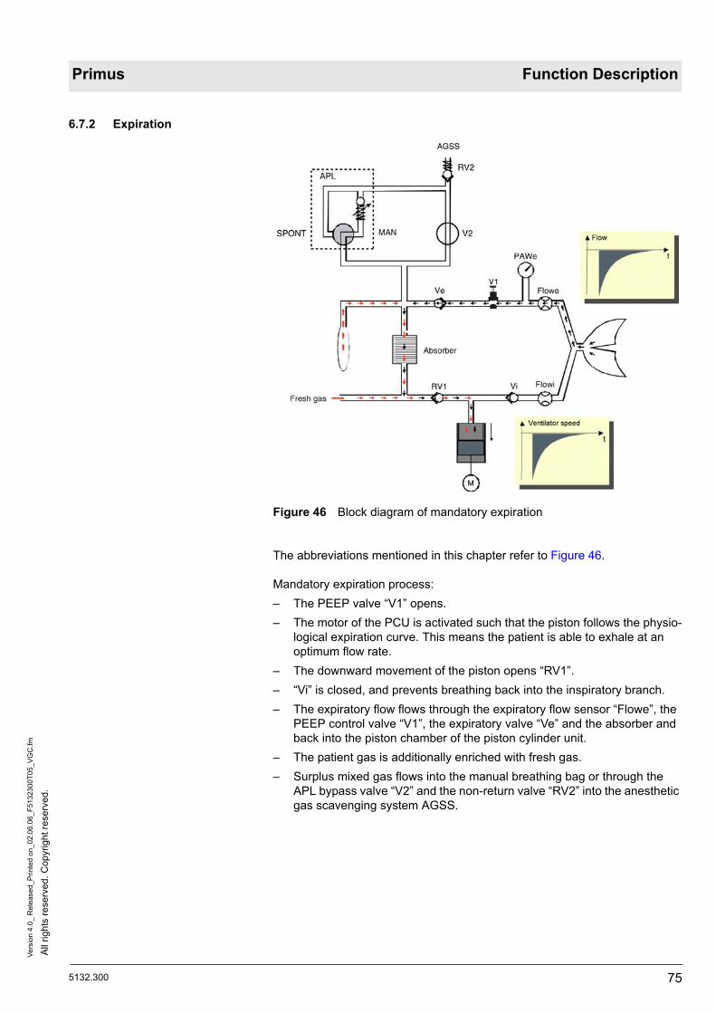
5132.300
All
right
s re
serv
ed. C
opyr
ight
rese
rved
.Ve
rsio
n 4.
0_ R
elea
sed_
Prin
ted
on_0
2.06
.06_
F513
2300
T05_
VG
C.fm
75
Primus Function Description
6.7.2 Expiration
Figure 46 Block diagram of mandatory expiration
The abbreviations mentioned in this chapter refer to Figure 46.
Mandatory expiration process:– The PEEP valve “V1” opens.– The motor of the PCU is activated such that the piston follows the physio-
logical expiration curve. This means the patient is able to exhale at an optimum flow rate.
– The downward movement of the piston opens “RV1”.– “Vi” is closed, and prevents breathing back into the inspiratory branch.– The expiratory flow flows through the expiratory flow sensor “Flowe”, the
PEEP control valve “V1”, the expiratory valve “Ve” and the absorber and back into the piston chamber of the piston cylinder unit.
– The patient gas is additionally enriched with fresh gas.– Surplus mixed gas flows into the manual breathing bag or through the
APL bypass valve “V2” and the non-return valve “RV2” into the anesthetic gas scavenging system AGSS.

All
right
s re
serv
ed. C
opyr
ight
rese
rved
.Ve
rsio
n 4.
0_ R
elea
sed_
Prin
ted
on_0
2.06
.06_
F513
2300
T05_
VG
C.fm
76 5132.300
Function Description Primus
Advantages of flow-optimized piston guidance:– The gas loss through the AGSS valve is minimized, because no non-
physiological overpressure is created in the expiratory phase.– The fresh gas consumption via the absorber is high as long as the fresh
gas flow is lower than the minute tidal volume “AMV”.– No non-physiological overpressure in the expiration phase. Consequently
there is also no intake of the diaphragm by “V1” (PEEP valve in breathing system).

5132.300
All
right
s re
serv
ed. C
opyr
ight
rese
rved
.Ve
rsio
n 4.
0_ R
elea
sed_
Prin
ted
on_0
2.06
.06_
F513
2300
T05_
VG
C.fm
77
Primus Function Description
6.8 Manual ventilation During manual ventilation of the patient, the switch of the APL valve is set to the MAN position.
Only the warnings/alarms for the lower O2 alarm, for the upper airway pres-sure (Paw) and for CO2 are enabled.
The piston of the VGC is in the upper end position in order to reduce the dead space volume of the ventilator.
The APL bypass valve “V2” is not actuated and is closed.
6.8.1 Inspiration
Figure 47 Block diagram of manual inspiration
The expiratory valve “Ve” is closed during the inspiratory phase.
Manual inspiration process:– When the manual breathing bag is compressed, the mixed gas (expira-
tory gas and fresh gas) flows through the absorber, the fresh gas isolation valve “RV1”, the inspiratory valve “Vi” and the flow sensor “Flowi” and then into the patient’s lung.
– The pressure sensor “PAWe” measures the airway pressure.– The APL valve limits the ventilation pressure.– The surplus mixed gas flows via the APL valve and the non-return valve
“RV2” into the anesthetic gas scavenging system AGSS.

All
right
s re
serv
ed. C
opyr
ight
rese
rved
.Ve
rsio
n 4.
0_ R
elea
sed_
Prin
ted
on_0
2.06
.06_
F513
2300
T05_
VG
C.fm
78 5132.300
Function Description Primus
6.8.2 Expiration
Figure 48 Block diagram of manual expiration
The inspiratory valve “Vi” is closed, and prevents expiratory gas from flowing back into the inspiratory branch.
Manual expiration process:– When the pressure is relieved from the manual breathing bag, the expira-
tory gas flows through the expiratory flow sensor “Flowe”, the PEEP con-trol valve “V1” and the expiratory valve “Ve” and then into the manual breathing bag.
– At the same time, fresh gas flows continuously during inspiration and expiration into the manual breathing bag.

5132.300
All
right
s re
serv
ed. C
opyr
ight
rese
rved
.Ve
rsio
n 4.
0_ R
elea
sed_
Prin
ted
on_0
2.06
.06_
F513
2300
T05_
VG
C.fm
79
Primus Function Description
6.9 Spontaneous breathing
During spontaneous breathing of the patient, the switch of the APL valve is set to the SPONT position. No gas pressure builds up in the compact breath-ing system. Only the warnings/alarms for the lower O2 alarm, for the upper airway pressure (Paw) and for CO2 are enabled. The piston of the KZE is moved to the upper end position in order to reduce the dead space volume of the ventilator. The APL bypass valve “V2” is not actuated.
6.9.1 Inspiration
Figure 49 Block diagram of spontaneous inspiration
The expiratory valve “Ve” is closed during the inspiratory phase, and so pre-vents inhalation of expiratory gas with CO2.
Inspiration process:– The patient inhales independently. During inhalation, the gas flows out of
the manual breathing bag through the absorber and is additionally enriched with fresh gas. The enriched mixed gas passes through the fresh gas isolation valve “RV1”, the inspiratory valve “Vi” and the inspira-tory flow sensor “Flowi” and then enters the patient’s lung.

All
right
s re
serv
ed. C
opyr
ight
rese
rved
.Ve
rsio
n 4.
0_ R
elea
sed_
Prin
ted
on_0
2.06
.06_
F513
2300
T05_
VG
C.fm
80 5132.300
Function Description Primus
6.9.2 Expiration
Figure 50 Block diagram of spontaneous expiration
During expiration, the inspiratory valve “Vi” remains closed thus preventing the expiratory gas from flowing back into the inspiratory branch.
Spontaneous expiration process:– During exhalation, the expiratory gas flows out of the patient’s lung
through the expiratory flow sensor “Flowe”, the PEEP control valve “V1” and the expiratory valve “Ve” into the manual breathing bag and the absorber.
– At the same time, fresh gas flows into the breathing bag.– If the pressure in the manual breathing bag is greater than the opening
pressure of “RV2”, the surplus gas mixture flows into the anesthetic gas scavenging system AGSS.

5132.300
All
right
s re
serv
ed. C
opyr
ight
rese
rved
.Ve
rsio
n 4.
0_ R
elea
sed_
Prin
ted
on_0
2.06
.06_
F513
2300
T05_
VG
C.fm
81
Primus Function Description
7 Ventilation modes with software ver-sion 2.n or higher
As of Primus software version 2.n, the ventilation modes terms for synchroni-zation and pressure support of spontaneously breathing patients will be changed into the four following terms:– “Volume Mode”.– “Pressure Mode”.– “Pressure Support Mode” (optional).– “Man./Spont Mode”.
7.1 “Volume Mode”
Figure 51 Volume-controlled ventilation with constant inspiratory flow
Ventilation mode Intended use
Volume-controlled ventilation mode with fixed mandatory tidal volume “VT” and frequency “Freq.”, including switchable synchronization and adjustable pressure support for spon-taneous breaths (optional “Pressure Support”).
Anesthesia in relaxed or partially relaxed patients with healthy lungs and in patients with cranio-cerebral trauma. The goal is to maintain a constant volume or a constant “et CO2”.

All
right
s re
serv
ed. C
opyr
ight
rese
rved
.Ve
rsio
n 4.
0_ R
elea
sed_
Prin
ted
on_0
2.06
.06_
F513
2300
T05_
VG
C.fm
82 5132.300
Function Description Primus
The following parameters determine the breathing cycle (see Figure 51):– Frequency “1/freq”.– Inspiratory time “Tinsp”.– Inspiratory flow level.– Inspiratory pause time “TIP:Tinsp”.– Tidal volume “VT”.
Figure 52 Synchronization of volume-controlled ventilation and spontaneous breathing
Synchronization is activated as soon as a trigger sensitivity value is entered. The message “sync” is displayed in the ventilation mode status field on the screen.
The flow trigger sensitivity controls the synchronization. The maximum time delay between the controlled ventilation breaths is adjusted by means of the frequency. To keep the frequency constant in the event of a premature trig-gering, the time is equalized in the next ventilation cycle.
A ventilation breath triggered by the patient is indicated by a continuous line (Figure 52/1) in the pressure curve and in the flow curve (trigger indicator). The active flow trigger window (Figure 52/2) corresponds to the last 25% of the relevant expiratory time.

5132.300
All
right
s re
serv
ed. C
opyr
ight
rese
rved
.Ve
rsio
n 4.
0_ R
elea
sed_
Prin
ted
on_0
2.06
.06_
F513
2300
T05_
VG
C.fm
83
Primus Function Description
Figure 53 Synchronization of volume-controlled ventilation and “Pressure Support” of spontaneous breathing
Pressure support is activated if, during volume-controlled ventilation, a value is entered for the level of the pressure support “ pps”.
The message “PressSupp” is displayed in the ventilation mode status field on the screen.
The flow trigger sensitivity and the “ pps” level control the synchronization or the pressure support. The maximum time delay between the controlled venti-lation breaths is adjusted by means of the frequency. To keep the frequency constant in the event of a premature triggering, the time is equalized in the next cycle.
If, at the time of pressure support activation, the patient was being ventilated without synchronization, automatic activation of the synchronization is initi-ated with the last trigger setting used.
If pressure support is deactivated with “OFF”, the synchronization is main-tained with the set value.
If the trigger is deactivated with “OFF”, then the pressure support will be deactivated automatically.

All
right
s re
serv
ed. C
opyr
ight
rese
rved
.Ve
rsio
n 4.
0_ R
elea
sed_
Prin
ted
on_0
2.06
.06_
F513
2300
T05_
VG
C.fm
84 5132.300
Function Description Primus
7.2 “Pressure Mode”
Figure 54 Pressure-controlled ventilation with decelerating flow
Pressure-controlled ventilation with fixed pressure limit “Pinsp” and frequency “1/freq”. Synchronization and adjustable pressure support of spontaneous breaths (optional) are switchable.
A continuous flow is applied to the patient during the inspiratory time “Tinsp”. The curve's rate of rise can be preset with the slope increase time “TSlope”. The maximum time delay between the controlled ventilation breaths is adjusted by means of the frequency. To keep the frequency constant in the event of a premature triggering, the time is equalized in the next cycle.
Changes to the lung compliance and the ventilation parameters affect the tidal volume.
Ventilation mode Intended use
Pressure-controlled ventilation with decelerating flow (PCB), with syn-chronization of mandatory breaths (SIMV-PC) and with pressure support of spontaneous breathing (“Pressure Support”).
Anesthesia in patients suffering from a lung disease (inhomogeneous lung), neonates, children mask ven-tilation, pulmonary fistulae, laryn-geal masks, inversed ratio ventilation, in relaxed or partially relaxed patients.

5132.300
All
right
s re
serv
ed. C
opyr
ight
rese
rved
.Ve
rsio
n 4.
0_ R
elea
sed_
Prin
ted
on_0
2.06
.06_
F513
2300
T05_
VG
C.fm
85
Primus Function Description
Figure 55 Synchronization of pressure-controlled ventilation and spontaneous breathing
Synchronization is activated as soon as a trigger value is entered.
The message “sync” is displayed in the ventilation mode status field on the screen.
The flow trigger sensitivity controls the synchronization.
A breath triggered by the patient is indicated by a continuous line (Figure 55/1) in the pressure curve and in the flow curve (trigger indicator). The active flow trigger window (Figure 55/2) corresponds to the last 25% of the relevant expiratory time.

All
right
s re
serv
ed. C
opyr
ight
rese
rved
.Ve
rsio
n 4.
0_ R
elea
sed_
Prin
ted
on_0
2.06
.06_
F513
2300
T05_
VG
C.fm
86 5132.300
Function Description Primus
Figure 56 Synchronization of pressure-controlled ventilation and “Pressure Support” of spontaneous breathing
Activation of pressure support during pressure-controlled ventilation is initi-ated by entering a value for the pressure support level “ pps”. The message “PressSupp” is displayed in the ventilation mode status field on the screen.
The flow trigger sensitivity and the “ pps” level control the synchronization or the pressure support.
If, at the time of pressure support activation, the patient was being ventilated without synchronization, automatic activation of the synchronization is initi-ated with the last “trigger” setting used.
If pressure support is deactivated with “OFF”, the synchronization is main-tained with the set value.
If the trigger is deactivated with “OFF”, then the pressure support will be deactivated automatically.

5132.300
All
right
s re
serv
ed. C
opyr
ight
rese
rved
.Ve
rsio
n 4.
0_ R
elea
sed_
Prin
ted
on_0
2.06
.06_
F513
2300
T05_
VG
C.fm
87
Primus Function Description
7.3 “Pressure Support Mode”
The ventilation mode “Pressure Support Mode” is an optional feature that must be activated.
Ventilation mode Intended use
Pressure support for spontaneous brathing. This option can be used in all mechanical ventilation modes. At the same time, this option is an inde-pendent ventilation mode.
The patient's spontaneous breathing effort is sup-ported by the following factors:– The flow trigger sensitivity controls the syn-
chronization.– The adjusted pressure setting is a measure of
the pressure support.
The curve's rate of rise can be preset with the slope increase time “Tslope”.
In addition, an apnea ventilation can be set via the minimum frequency “Freqmin”.
If the patient does not breathe spontaneously, the ventilator is activated automatically dependent on the set minimum frequency “Freqmin”. The sub-sequent ventilation breath is not a mandatory ventilation breath. The patient can always stop the mandatory ventilation breath by his/her own breathing activity.
Anesthesia in sponta-neously breathing patients with laryngeal masks during surgeries without muscle relax-ants.

All
right
s re
serv
ed. C
opyr
ight
rese
rved
.Ve
rsio
n 4.
0_ R
elea
sed_
Prin
ted
on_0
2.06
.06_
F513
2300
T05_
VG
C.fm
88 5132.300
Function Description Primus
Figure 57 Spontaneous breathing support
The flow trigger sensitivity and the “ pps” level control the synchronization or the pressure support of the spontaneous breathing effort. The curve's rate of rise can be preset with the slope increase time “Tslope”.
In addition, an apnea ventilation can be set via the minimum frequency “1/freqmin”. “1/freqmin” controls the automatic triggering of the ventilator when the patient is not breathing spontaneously. It is not a mandatory ventila-tion breath from the ventilator. The patient can always stop the breath trig-gered by the ventilator by his/her breathing activity. This breath is not provided with a trigger indicator.
7.4 “Man./Spont Mode”Ventilation mode Intended use
Manual ventilation or assisted venti-lation and spontaneous breathing.
Anesthesia induction/recovery and in emergency situations.

5132.300
All
right
s re
serv
ed. C
opyr
ight
rese
rved
.Ve
rsio
n 4.
0_ R
elea
sed_
Prin
ted
on_0
2.06
.06_
F513
2300
T05_
VG
C.fm
89
Primus Function Description
7.5 Switching ventila-tion modes
When switching to another ventilation mode, the presettings of the previous mode's parameters are transferred or usefully derived.
Identical parameters in both ventilation modes (Freq., TINSP, PEEP, pps, trigger) are transferred directly.
7.6 HLM mode The HLM mode (“HLM” = heart-lung machine) enables an alarm-free patient monitoring during extracorporeal oxygenization of the patient by means of a heart-lung machine.
The following conditions apply in the HLM mode:– All gas concentrations are measured independent of the breathing phase.– The CO2 apnea alarm, the pressure apnea alarm, and the SpO2 monitor-
ing alarms are deactivated.
The HLM mode remains active when switching from one ventilation mode to another. Switching to standby mode will deactivate the HLM mode.
The function description relating to the Power pack follows.
Switching ventila-tion modes
Transfer of settings
Volume-controlled to pressure-controlled.
The measured parameter “Pplat” is applied as new parameter “Pinsp”.
Pressure-controlled to volume-controlled.
The new tidal volume “VT” is transferred from the measured minute volume “MV” and the set fre-quency “Freq.”. Only the mechanically applied minute volume is used in this case.
Pressure-supported breaths by the patients are not taken into consideration.
Automatic ventilation modes to “Pressure Support” (optional).
The set PEEP, “ pps” and trigger are transferred.
If “ pps” and/or trigger were set to “OFF”, the most recently used values are transferred to pressure support, otherwise the configured default settings.
Pressure support (optional) to automatic ventilation modes.
The set PEEP, “ pps” and the trigger are trans-ferred.
The other parameters correspond to the most recently used settings, otherwise to the configured default settings.

All
right
s re
serv
ed. C
opyr
ight
rese
rved
.Ve
rsio
n 4.
0_ R
elea
sed_
Prin
ted
on_0
2.06
.06_
F513
2300
T05_
VG
C.fm
90 5132.300
Function Description Primus

5132.300
All
right
s re
serv
ed. C
opyr
ight
rese
rved
.Ve
rsio
n 1.
0_ R
elea
sed_
Prin
ted
on_0
2.06
.06_
F513
2300
T06_
Net
ztei
l.fm
91
Primus Function Description
8 Power pack This section describes the power pack. The power pack comprises the elec-tronics component and two UPS batteries (UPS = Uninterruptible Power Sup-ply).
Figure 58 Power pack position
In the 'Block diagrams' section you will find a block diagram of the power pack.
8.1 Power pack input The power pack generates the direct voltage for the Primus components and the charging voltage for the UPS batteries.
The power pack input processes alternating voltages from 85 to 265 V (45 to 65 Hz).
In the event of a power failure or power pack failure, an automatic switch is made to the UPS. The connection to the mains voltage is via a 16 A inlet con-nector for non-heating apparatus.
The inlet connector for non-heating apparatus is protected by a mechanical locking device (to EN 740) to prevent it being pulled out unintentionally.
The power pack has a grounding connection with a 6.3 mm contact.

All
right
s re
serv
ed. C
opyr
ight
rese
rved
.Ve
rsio
n 1.
0_ R
elea
sed_
Prin
ted
on_0
2.06
.06_
F513
2300
T06_
Net
ztei
l.fm
92 5132.300
Function Description Primus
8.2 Power switch
Figure 59 Power switch position
The power switch is connected via the NEUTRAL POINT PCB to the power pack. The power switch switches an auxiliary voltage of 5 V.
8.3 Output voltages and currents
The power pack delivers the following output voltages:– 3x 20 to approx. 30 Volts (battery voltage)– 3x regulated output voltage of 12 Volts.
The voltages are battery-buffered.
Voltage Unit on Unit off applies to:
U1: 24 V, 10 mA
Always present Battery-buffered RAM in GUI
U2: 24 V, 10 VA
Present as soon as mains plug is connected or unit is switched on.
Pressure sensors of CS and compressed gas cylinders. CS LEDs, mixer LEDs

5132.300
All
right
s re
serv
ed. C
opyr
ight
rese
rved
.Ve
rsio
n 1.
0_ R
elea
sed_
Prin
ted
on_0
2.06
.06_
F513
2300
T06_
Net
ztei
l.fm
93
Primus Function Description
A higher power demand than 600 W is supplied from the batteries.
The switched output voltages (U3 to U6) release with a delay after operation of the switch. The delay is 10 seconds, but can be altered with the CAN pro-tocol to between 5 and 15 seconds.
The power pack is short-circuit-proof and shuts off if operating current = Imax and U < Umin for t > 20 ms.
8.4 Secondary connec-tor
The connector for the voltage outputs is a 24-pin plug. The connector addi-tionally carries the CAN signals, the switching contacts of the power switch and the control wires for the power and battery LEDs on the front panel.
8.5 UPS batteries The two UPS batteries are fitted separately in the housing, behind the power pack. The battery capacity is sufficient to run the Primus for at least 30 minutes.
The Primus power pack performs an automatic battery test every 30 days. The battery test has no effect on the operation of the Primus. In testing, the batteries are discharged by 20% of the available capacity. The battery condi-tion is determined from the resultant battery curve.
The charging time for fully discharged batteries is a maximum of 10 hours. The batteries’ charging management system takes into account the battery temperature. The battery temperature is measured with a temperature sensor (NTC) directly at the batteries.
The battery charging management system prevents exhaustive discharge. If the battery voltage falls below 20 V the power pack shuts down the Primus. If the battery voltage is below 20 V the power pack cannot be powered up.
U3: 24 V, 1-23 A
Present 10 sec-onds after the power switch is switched on (inde-pendent of mains voltage).
Releases with a delay of approx. 10 s after operation of the switch
- GUI - Mixer - VGC
U4: 12 V, 1-10 A
- IRIA - ILCA - VGC - small pneutronic valves
U5: 12 V, 10 VA
Present as soon as the unit is switched on.
Fan for VGC and mixer
U6: 12 V, 10 VA
Fan for IRIA and opti-cal Diva
Voltage Unit on Unit off applies to:

All
right
s re
serv
ed. C
opyr
ight
rese
rved
.Ve
rsio
n 1.
0_ R
elea
sed_
Prin
ted
on_0
2.06
.06_
F513
2300
T06_
Net
ztei
l.fm
94 5132.300
Function Description Primus
8.6 Power pack CAN communication
With the CAN (Controller Area Network) bus data can be exchanged between the power pack and the other modules. The higher-level software protocol is SABUS (Sensor and Actuator BUS).
The power pack has a CAN 2.0 B compatible interface. The interface trans-fers data and status information in both directions.
The power pack sends its data periodically, every 500 ms, to the GUI.
The power pack CAN bus transfers the following data:– Power pack version– Power pack hours. Total time in operation of power pack.– Battery hours. Power pack operating time in battery mode. The figure is
given in Ah (Ampere hours). – Time remaining: Indicates the time remaining in seconds until the power
pack will shut off.– Battery type: Indication of battery type.– Power pack details: e.g. self-test errors.– Date: To determine how long the unit was switched off.– Switch power pack off. The power pack shuts when the remaining time
expires. The shut-off is aborted as soon as the value “0” (->switch off power pack = no) is received by the power pack.
8.7 Power failure warn-ing
The power pack hooter sounds under the following conditions:– About 1 second after power-up for about 1 second.– If the “Hooter on” error is delivered over the CAN bus. For as long as the
CAN controller is in “Reset” mode.– When the power switch is set to “On” and the batteries are flat or have
been removed.– If no CAN messages are received for the power pack during operation for
more than 15 seconds after receipt of the first CAN message.– In case of power failure.
The hooter sounds for as long as the error condition persists, up to a maxi-mum of 30 seconds +-5 seconds.
The function description relating to the operating modes follows.

5132.300
All
right
s re
serv
ed. C
opyr
ight
rese
rved
.Ve
rsio
n 1.
0_ R
elea
sed_
Prin
ted
on_0
2.06
.06_
F513
2300
T07_
Bet
riebs
mod
es.fm
95
Primus Function Description
9 Operating modes This section details the individual operating modes of the Primus.
9.1 Cold start When the Primus is switched on, the unit starts up with a so-called cold start.
During the cold start the user checks and confirms the checklist on the dis-play. Then the user is prompted to connect the Y-piece to the patient unit and set the APL valve to 30 mbar (MAN setting).
In the self-test which follows the unit checks its system components. Any errors detected are indicated on the display. If no errors occurred, the Primus switches to “ready”.
The self-test can be interrupted for an emergency start.
9.2 Standby mode When the self-test is completed, standby mode is automatically activated. In this operating mode no CS gas is consumed. No fresh gas supply is possible (except for fresh gas through the safety O2 adjuster “VSFC”). The user can select all ventilation parameters, the fresh gas flow setting and the ventilation mode.
Alarms and messages are indicated on the display.
9.3 Shutdown All Primus components are switched off from the central power switch. Only the charging circuit for the UPS batteries is permanently in operation.
When the Primus is off, the following alarms are inactive:– Mains power failure– CS pressure failure
9.4 Safety mode If the software detects a serious error during fresh gas supply or ventilation, individual components (such as the mixer) or the entire Primus unit switch to safety mode.
In safety mode it is possible to provide the patient with manual ventilation or spontaneous breathing. The fresh gas is then supplied by the adjustable safety O2 flow control valve “VSFC”.
9.4.1 Safety O2 flow The safety O2 flow is usually set by the user with the safety O2 adjuster and routed through the vaporizer.
The patient is supplied with O2 (4 L/min to 12 L/min) by the “VSFC”. As a result, anaesthetic gas metering is possible. This operating mode is usually activated by the user under the following conditions:– In case of a total system failure. Primus switches to Safety mode.– Power failure or UPS batteries flat.
In this case the control range of the O2 flow is 4 L/min to 12 L/min. If the safety O2 flow is activated in normal mode, a warning appears on the display. The mixer electronics additionally limit the fresh gas flow to 3 L/min. The fresh gas settings are then greyed on the display (from software release 1.n).

All
right
s re
serv
ed. C
opyr
ight
rese
rved
.Ve
rsio
n 1.
0_ R
elea
sed_
Prin
ted
on_0
2.06
.06_
F513
2300
T07_
Bet
riebs
mod
es.fm
96 5132.300
Function Description Primus
9.5 Alarm system The Primus has a common alarm system for visual and acoustic indication of ventilator and monitoring alarms. Error messages are indicated on the dis-play.
There are three categories of alert:– Alarm (category I)– Warning (category II)– Notification (category III
The function description relating to the cylinder pressure reducers follows.

5132.300
All
right
s re
serv
ed. C
opyr
ight
rese
rved
.Ve
rsio
n 2.
0_ R
elea
sed_
Prin
ted
on_0
2.06
.06_
F513
2300
T08_
Flas
chen
druc
kmin
dere
r.fm
97
Primus Function Description
10 Cylinder pressure reducer
This section describes the pressure reducer for the high-pressure cylinders (option).
Figure 60 Sectional drawing of cylinder pressure reducer; for legend see Table 26
Table 26 Legend to Figure 60
The abbreviations occurring in the following text relate to Figure 60 .
Abbreviation Function
H Adjusting screw
Fst Adjusting spring force
M Diaphragm
Fpa Press force
pem Sensor/pressure gauge connection
pe Input pressure
pa Low pressure
Vs Valve seat
Vk Valve cone

All
right
s re
serv
ed. C
opyr
ight
rese
rved
.Ve
rsio
n 2.
0_ R
elea
sed_
Prin
ted
on_0
2.06
.06_
F513
2300
T08_
Flas
chen
druc
kmin
dere
r.fm
98 5132.300
Function Description Primus
The following pressure reducer types exist:– AIR, from 200 bar to 5 bar– O2, from 200 bar to 5 bar– N2O, from 60 bar to 5 bar
The diaphragm (M) regulates the pressure.
When the adjusting screw “H” is at the anti-clockwise stop limit the adjusting spring force “Fst” is at its lowest. The valve cone “Vk” is pressed into the valve seat by the spring underneath it and interrupts the gas flow.“pa” rises.
When the adjusting screw (H) is turned clockwise the adjusting spring force (Fst) increases. The valve cone is pressed down by the diaphragm, the valve opens and the low pressure “pa” rises.
A constant low pressure “pa” results from the equilibrium of forces (Fpa = Fst).
The low pressure is preset to between 5 and 6 bar (USA = 2.7 bar and 3.5 bar).
If the low pressure drops, the force “Fpa” decreases and the adjusting spring force “Fst” opens the valve.
If the low pressure rises, the force “Fst” increases and compresses the adjusting spring. The valve is closed accordingly.
The pre-tension of the spring is set by the manufacturer, and can be adjusted by the DrägerService technician.

5132.300
All
right
s re
serv
ed. C
opyr
ight
rese
rved
.Ve
rsio
n 2.
0_ R
elea
sed_
Prin
ted
on_0
2.06
.06_
F513
2300
T08_
Flas
chen
druc
kmin
dere
r.fm
99
Primus Function Description
If the valve cone does not close, the internal blow-off valve “Sv” limits the low pressure (see Figure 61). The opening pressure is between 6.6 bar and 8.5 bar.
Figure 61 Sectional drawing of blow-off valve
The function description relating to the vaporizer follows.

All
right
s re
serv
ed. C
opyr
ight
rese
rved
.Ve
rsio
n 2.
0_ R
elea
sed_
Prin
ted
on_0
2.06
.06_
F513
2300
T08_
Flas
chen
druc
kmin
dere
r.fm
100 5132.300
Function Description Primus

5132.300
All
right
s re
serv
ed. C
opyr
ight
rese
rved
.Ve
rsio
n 1.
0_ R
elea
sed_
Prin
ted
on_0
2.06
.06_
F513
2300
T09_
Vapo
r.fm
101
Primus Function Description
11 Vaporizer The interlock system prevents two vaporizers from operating simultaneously.
The active vaporizer enriches the mixed gas with anaesthetic.
For a detailed description refer to the relevant Instructions for Use of the vaporizers used.

All
right
s re
serv
ed. C
opyr
ight
rese
rved
.Ve
rsio
n 1.
0_ R
elea
sed_
Prin
ted
on_0
2.06
.06_
F513
2300
T09_
Vapo
r.fm
102 5132.300
Function Description Primus
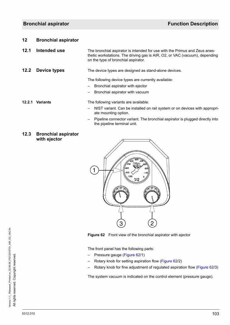
5312.010
All
right
s re
serv
ed. C
opyr
ight
rese
rved
.Ve
rsio
n 1.
1_ R
elea
sed_
Prin
ted
on_0
2.06
.06_
F531
2010
T01_
AIR
_O2_
VAC
.fm
103
Bronchial aspirator Function Description
12 Bronchial aspirator
12.1 Intended use The bronchial aspirator is intended for use with the Primus and Zeus anes-thetic workstations. The driving gas is AIR, O2, or VAC (vacuum), depending on the type of bronchial aspirator.
12.2 Device types The device types are designed as stand-alone devices.
The following device types are currently available:– Bronchial aspirator with ejector– Bronchial aspirator with vacuum
12.2.1 Variants The following variants are available:– NIST variant. Can be installed on rail system or on devices with appropri-
ate mounting option. – Pipeline connector variant. The bronchial aspirator is plugged directly into
the pipeline terminal unit.
12.3 Bronchial aspirator with ejector
Figure 62 Front view of the bronchial aspirator with ejector
The front panel has the following parts:– Pressure gauge (Figure 62/1) – Rotary knob for setting aspiration flow (Figure 62/2)– Rotary knob for fine adjustment of regulated aspiration flow (Figure 62/3)
The system vacuum is indicated on the control element (pressure gauge).

All
right
s re
serv
ed. C
opyr
ight
rese
rved
.Ve
rsio
n 1.
1_ R
elea
sed_
Prin
ted
on_0
2.06
.06_
F531
2010
T01_
AIR
_O2_
VAC
.fm
104 5312.010
Function Description Bronchial aspirator
12.3.1 Pneumatics (ejector)
Figure 63 Pneumatics of the bronchial aspirator with ejector
Table 27 Legend to Figure 63
The position numbers and valve positions mentioned in this chapter refer to Figure 63.
The driving gas (AIR or O2) enters into the bronchial aspirator through the supply pressure connector.
The operating mode selector (2) is used to select the following operating modes:– OFF (valve position “b”). The bronchial aspirator is switched off.– Regulated flow (valve position “a”). The driving gas passes through the
control valve (3). The control valve adjusts the ejector driving gas thus generating the required vacuum.
– Maximum flow (valve position “c”). The supply pressure is fed directly to the ejector. This generates a maximum vacuum in the suction system.
The non-return valve (6) is used as a mount for the bacterial filter. In the event of malfunctions, the non-return valve makes sure no positive pressure is present in the vacuum system.
Pos. Meaning
1 Supply pressure connector (O2/AIR-NIST or AIR-NIST or O2/AIR pipeline connector)
2 Operating mode selector
3 Control valve
4 Ejector
5 Pressure gauge
6 Non-return valve (bacterial filter mount)
7 bacterial filter
8 Collector

5312.010
All
right
s re
serv
ed. C
opyr
ight
rese
rved
.Ve
rsio
n 1.
1_ R
elea
sed_
Prin
ted
on_0
2.06
.06_
F531
2010
T01_
AIR
_O2_
VAC
.fm
105
Bronchial aspirator Function Description
The bacterial filter (7) makes sure that no particles or bacteria from the collec-tor (8) enter the suction system. The filter material can block fluids up to a vacuum pressure of 920 mbar.
The pneumatic circuit has the following advantages:– In the “regulated flow” position only as much driving gas is used as
required to generate the vacuum.– Fast toggling between regulated flow and maximum flow.– Less noise by reduced gas consumption.– No suction flow loss by bypass openings.
12.4 Bronchial aspirator with vacuum
Figure 64 Front view of the bronchial aspirator with vacuum
The front panel has the following parts:– Pressure gauge (Figure 64/1) – Vacuum regulator (Figure 64/2)– Operating mode selector (Figure 64/3)
The system vacuum is indicated on the control element (pressure gauge).

All
right
s re
serv
ed. C
opyr
ight
rese
rved
.Ve
rsio
n 1.
1_ R
elea
sed_
Prin
ted
on_0
2.06
.06_
F531
2010
T01_
AIR
_O2_
VAC
.fm
106 5312.010
Function Description Bronchial aspirator
12.4.1 Pneumatics (vacuum)
Figure 65 Pneumatics of the bronchial aspirator with vacuum
Table 28 Legend to Figure 65
The position numbers and valve positions mentioned in this chapter refer to Figure 65.
The vacuum enters into the bronchial aspirator through the VAC connector (1).
The operating mode selector (2) is used to select the following operating modes:– OFF (valve position “b”). The bronchial aspirator is switched off.– Regulated flow (valve position “a”). The generated vacuum depends on
the position of the vacuum regulator (3). The vacuum is indicated by the pressure gauge (4).
– Maximum flow (valve position “c”). The vacuum is fed directly to the non-return valve (5). This generates a maximum vacuum in the suction sys-tem.
The non-return valve (5) is used as a mount for the bacterial filter.
Pos. Meaning
1 VAC connector (VAC-NIST or VAC pipeline connector)
2 Operating mode selector
3 Vacuum regulator
4 Pressure gauge
5 Non-return valve (bacterial filter mount)
6 bacterial filter
7 Collector

5312.010
All
right
s re
serv
ed. C
opyr
ight
rese
rved
.Ve
rsio
n 1.
1_ R
elea
sed_
Prin
ted
on_0
2.06
.06_
F531
2010
T01_
AIR
_O2_
VAC
.fm
107
Bronchial aspirator Function Description
The bacterial filter (6) makes sure that no particles or bacteria from the collec-tor (7) enter the suction system. The filter material can block fluids up to a vacuum pressure of 920 mbar.
The pneumatic circuit has the following advantages:– Fast toggling between regulated flow and maximum flow.– High-quality vacuum control.– No suction flow loss by bypass openings.

All
right
s re
serv
ed. C
opyr
ight
rese
rved
.Ve
rsio
n 1.
1_ R
elea
sed_
Prin
ted
on_0
2.06
.06_
F531
2010
T01_
AIR
_O2_
VAC
.fm
108 5312.010
Function Description Bronchial aspirator

Primus Function Description
5132.300 109
All
right
s re
serv
ed. C
opyr
ight
rese
rved
.Ve
rsio
n 3.
0_ R
elea
sed_
Prin
ted
on_0
2.06
.06_
F513
2300
T12_
Blo
cksc
haltb
ilder
.fm
13B
lock
dia
gram
s an
d pn
eum
atic
com
pone
nts
layo
ut
13.1
Intr
oduc
tion
The
follo
win
g bl
ock
diag
ram
s an
d th
e pn
eum
atic
com
pone
nts
layo
ut a
re c
ompo
nent
ele
men
ts o
f the
func
tion
desc
riptio
n of
the
Prim
us.
Figu
re 6
6 P
rimus
blo
ck d
iagr
am, d
etai
led
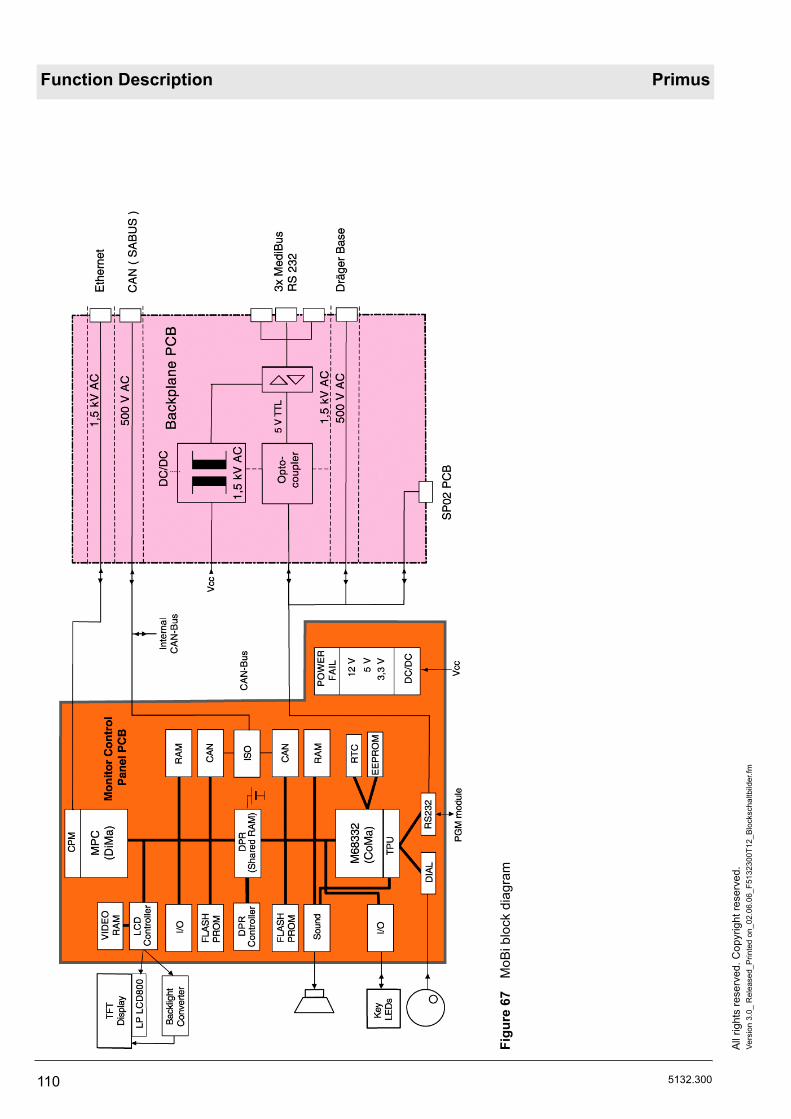
Function Description Primus
110 5132.300
All r
ight
s re
serv
ed. C
opyr
ight
rese
rved
.Ve
rsio
n 3.
0_ R
elea
sed_
Prin
ted
on_0
2.06
.06_
F513
2300
T12_
Bloc
ksch
altb
ilder
.fm
Figu
re 6
7 M
oBi b
lock
dia
gram

Primus Function Description
5132.300 111
All
right
s re
serv
ed. C
opyr
ight
rese
rved
.Ve
rsio
n 3.
0_ R
elea
sed_
Prin
ted
on_0
2.06
.06_
F513
2300
T12_
Blo
cksc
haltb
ilder
.fm
Figu
re 6
8 S
-Box
, blo
ck d
iagr
am, d
etai
led

Function Description Primus
112 5132.300
All r
ight
s re
serv
ed. C
opyr
ight
rese
rved
.Ve
rsio
n 3.
0_ R
elea
sed_
Prin
ted
on_0
2.06
.06_
F513
2300
T12_
Bloc
ksch
altb
ilder
.fm
Figu
re 6
9 P
GM
pne
umat
ics
diag
ram
, det
aile
d

Primus Function Description
5132.300 113
All
right
s re
serv
ed. C
opyr
ight
rese
rved
.Ve
rsio
n 3.
0_ R
elea
sed_
Prin
ted
on_0
2.06
.06_
F513
2300
T12_
Blo
cksc
haltb
ilder
.fm
Figu
re 7
0 P
GM
2 pn
eum
atic
s di
agra
m, d
etai
led

Function Description Primus
114 5132.300
All r
ight
s re
serv
ed. C
opyr
ight
rese
rved
.Ve
rsio
n 3.
0_ R
elea
sed_
Prin
ted
on_0
2.06
.06_
F513
2300
T12_
Bloc
ksch
altb
ilder
.fm
Figu
re 7
1 P
GM
2 bl
ock
diag
ram

Primus Function Description
5132.300 115
All
right
s re
serv
ed. C
opyr
ight
rese
rved
.Ve
rsio
n 3.
0_ R
elea
sed_
Prin
ted
on_0
2.06
.06_
F513
2300
T12_
Blo
cksc
haltb
ilder
.fm
Figu
re 7
2 M
OP
S P
CB
blo
ck d
iagr
am

Function Description Primus
116 5132.300
All r
ight
s re
serv
ed. C
opyr
ight
rese
rved
.Ve
rsio
n 3.
0_ R
elea
sed_
Prin
ted
on_0
2.06
.06_
F513
2300
T12_
Bloc
ksch
altb
ilder
.fm
Figu
re 7
3 V
GC
blo
ck d
iagr
am

Primus Function Description
5132.300 117
All
right
s re
serv
ed. C
opyr
ight
rese
rved
.Ve
rsio
n 3.
0_ R
elea
sed_
Prin
ted
on_0
2.06
.06_
F513
2300
T12_
Blo
cksc
haltb
ilder
.fm
Figu
re 7
4 C
PU
PR
IMU
S P
CB
blo
ck d
iagr
am, i
nsta
lled
in m
ixer
and
VG
C

Function Description Primus
118 5132.300
All r
ight
s re
serv
ed. C
opyr
ight
rese
rved
.Ve
rsio
n 3.
0_ R
elea
sed_
Prin
ted
on_0
2.06
.06_
F513
2300
T12_
Bloc
ksch
altb
ilder
.fm
Figu
re 7
5 M
ixer
PC
B b
lock
dia
gram

Primus Function Description
5132.300 119
All
right
s re
serv
ed. C
opyr
ight
rese
rved
.Ve
rsio
n 3.
0_ R
elea
sed_
Prin
ted
on_0
2.06
.06_
F513
2300
T12_
Blo
cksc
haltb
ilder
.fm
Figu
re 7
6 P
ower
pac
k/U
PS
blo
ck d
iagr
am

Function Description Primus
120 5132.300
All r
ight
s re
serv
ed. C
opyr
ight
rese
rved
.Ve
rsio
n 3.
0_ R
elea
sed_
Prin
ted
on_0
2.06
.06_
F513
2300
T12_
Bloc
ksch
altb
ilder
.fm

121
Maintenance Procedures

122

5132.300
All
right
s re
serv
ed. C
opyr
ight
rese
rved
.Ve
rsio
n 1.
1_ R
elea
sed_
Prin
ted
on_0
2.06
.06_
W51
3230
0T01
_Sic
herh
eits
hinw
eise
.fm
123
Primus Maintenance Procedures
1 Safety precautionsWARNINGRisk of explosion!Always make sure parts which come into contact with oxygen are free of grease and oil prior to fitting.
WARNINGHazardous voltage!Do not touch live conductors/parts when Primus’ power plug is plugged into the AC outlet.Switch off the Primus at the power switch (main switch).Unplug the power plug from the non-heating apparatus socket on the power pack. To do so, turn the mechanical guard aside.
CAUTIONElectrostatic discharge!Electrostatic discharge may damage electrostatic sensitive devices.When handling electrostatic sensitive devices always use an anti-static mat and a wrist strap.
WARNINGFunction and safety tests after servicing!After carrying out servicing work, perform a function test and a test of electrical safety.

All
right
s re
serv
ed. C
opyr
ight
rese
rved
.Ve
rsio
n 1.
1_ R
elea
sed_
Prin
ted
on_0
2.06
.06_
W51
3230
0T01
_Sic
herh
eits
hinw
eise
.fm
124 5132.300
Maintenance Procedures Primus

5132.300
All
right
s re
serv
ed. C
opyr
ight
rese
rved
.Ve
rsio
n 1.
0_ R
elea
sed_
Prin
ted
on_0
2.06
.06_
W51
3230
0T02
_Rue
ckw
and
_oef
fnen
.fm
125
Primus Maintenance Procedures
2 Rear panel
2.1 Rear panel removal 1. Follow the safety instructions (see Safety precautions). 2. Remove the five rear panel fixing screws (see Figure 1).
Figure 1 Rear panel fixing screws
3. Withdraw the rear panel from the unit and place it down safely.
2.2 Rear panel fitting 1. Re-assemble using the reverse (logical) sequence of that used for disas-sembly.
2.2.1 Rear panel final check 1. Are all screws fixed?2. Is the rear panel fitted in place without mechanical strain?3. Electrical safety test.

All
right
s re
serv
ed. C
opyr
ight
rese
rved
.Ve
rsio
n 1.
0_ R
elea
sed_
Prin
ted
on_0
2.06
.06_
W51
3230
0T02
_Rue
ckw
and
_oef
fnen
.fm
126 5132.300
Maintenance Procedures Primus

5132.300
All
right
s re
serv
ed. C
opyr
ight
rese
rved
.Ve
rsio
n 1.
0_ R
elea
sed_
Prin
ted
on_0
2.06
.06_
W51
3230
0T10
_Bak
terie
nfilt
er_B
ronc
hial
absa
ugun
g.fm
127
Primus Maintenance Procedures
3 Replacing bronchial suction device bac-terial filter
1. Remove the old bacterial filter from the underside of the bronchial suction device and replace it (see Figure 2/1).
Figure 2 Bacterial filter position
2. Carry out a functional test.

All
right
s re
serv
ed. C
opyr
ight
rese
rved
.Ve
rsio
n 1.
0_ R
elea
sed_
Prin
ted
on_0
2.06
.06_
W51
3230
0T10
_Bak
terie
nfilt
er_B
ronc
hial
absa
ugun
g.fm
128 5132.300
Maintenance Procedures Primus

5132.300
All
right
s re
serv
ed. C
opyr
ight
rese
rved
.Ve
rsio
n 1.
0_ R
elea
sed_
Prin
ted
on_0
2.06
.06_
W51
3230
0T05
_Filt
erm
atte
_PG
M.fm
129
Primus Maintenance Procedures
4 Replacing filter mat on PGM fan
1. Take out the filter on the rear of the PGM (see Figure 3) and replace it with a new one.
Figure 3 PGM, filter

All
right
s re
serv
ed. C
opyr
ight
rese
rved
.Ve
rsio
n 1.
0_ R
elea
sed_
Prin
ted
on_0
2.06
.06_
W51
3230
0T05
_Filt
erm
atte
_PG
M.fm
130 5132.300
Maintenance Procedures Primus

5132.300
All
right
s re
serv
ed. C
opyr
ight
rese
rved
.Ve
rsio
n 2.
1_ R
elea
sed_
Prin
ted
on_0
2.06
.06_
W51
3230
0T07
_Bak
terie
nfilt
er_N
afio
n_PG
M.fm
131
Primus Maintenance Procedures
5 Replacing bacterial filter and Nafion tube in PGM
5.1 Removing the PGM
5.1.1 Removing the PGM housing
1. Remove the three fixing screws (see Figure 4).
Figure 4 Fixing screws
2. Remove the four side panel fixing screws (see Figure 5).
Figure 5 Side panel fixing screws

All
right
s re
serv
ed. C
opyr
ight
rese
rved
.Ve
rsio
n 2.
1_ R
elea
sed_
Prin
ted
on_0
2.06
.06_
W51
3230
0T07
_Bak
terie
nfilt
er_N
afio
n_PG
M.fm
132 5132.300
Maintenance Procedures Primus
3. Slide the top cover aside (see Figure 6).
Figure 6 Top cover
4. Place the top cover next to the housing. Tilt the side panel slightly (Figure 7/1) and place the adapter board (Figure 7/2) next to the housing.
Figure 7 Opened PGM housing

5132.300
All
right
s re
serv
ed. C
opyr
ight
rese
rved
.Ve
rsio
n 2.
1_ R
elea
sed_
Prin
ted
on_0
2.06
.06_
W51
3230
0T07
_Bak
terie
nfilt
er_N
afio
n_PG
M.fm
133
Primus Maintenance Procedures
5.2 Replacing the bacte-rial filter
1. Remove the old bacterial filter (Figure 8/1) and replace it with the new one.
Figure 8 Bacterial filter
5.3 Replacing the Nafion tube
1. Remove the old Nafion tube (Figure 9) and replace it with the new one.
Figure 9 Nafion tube connections
NOTEAlways use gloves when replacing the Nafion tube.

All
right
s re
serv
ed. C
opyr
ight
rese
rved
.Ve
rsio
n 2.
1_ R
elea
sed_
Prin
ted
on_0
2.06
.06_
W51
3230
0T07
_Bak
terie
nfilt
er_N
afio
n_PG
M.fm
134 5132.300
Maintenance Procedures Primus
5.4 Fitting the PGM housing (new)
1. Refit the PGM housing in the reverse order of its removal, as described in section 5.1.1 Removing the PGM housing.
Check the following points during the various operations: 2. Are all electrical connections plugged in? Are all tubes connected and
without kinks? Are all components firmly screwed down inside the PGM module? Do all housing interlocks fit together (see Figure 10/1)? Is the Teflon plate fitted over the IRIA (see Figure 10/2)?
Figure 10 Housing interlocks and insulating foil

5132.300
All
right
s re
serv
ed. C
opyr
ight
rese
rved
.Ve
rsio
n 2.
1_ R
elea
sed_
Prin
ted
on_0
2.06
.06_
W51
3230
0T07
_Bak
terie
nfilt
er_N
afio
n_PG
M.fm
135
Primus Maintenance Procedures
3. Mount the top cover, lift slightly at the rear (see Figure 11), and slide it completely over the housing.
Figure 11 Fitting the cover
4. Carry out function and electrical safety tests.

All
right
s re
serv
ed. C
opyr
ight
rese
rved
.Ve
rsio
n 2.
1_ R
elea
sed_
Prin
ted
on_0
2.06
.06_
W51
3230
0T07
_Bak
terie
nfilt
er_N
afio
n_PG
M.fm
136 5132.300
Maintenance Procedures Primus

5132.300
All
right
s re
serv
ed. C
opyr
ight
rese
rved
.Ve
rsio
n 1.
0_ R
elea
sed_
Prin
ted
on_0
2.06
.06_
W51
3230
0T03
_Filt
erm
atte
_Geh
Dec
kel.f
m
137
Primus Maintenance Procedures
6 Cleaning or replac-ing filter mat in housing cover
6.1 Filter mat removal 1. Remove the four housing cover fixing screws (see Figure 12).
Figure 12 Housing cover fixing screws
2. On the rear of the unit slacken the three fixing screws about four turns (see Figure 13).
Figure 13 Unit rear fixing screws

All
right
s re
serv
ed. C
opyr
ight
rese
rved
.Ve
rsio
n 1.
0_ R
elea
sed_
Prin
ted
on_0
2.06
.06_
W51
3230
0T03
_Filt
erm
atte
_Geh
Dec
kel.f
m
138 5132.300
Maintenance Procedures Primus
3. Raise the housing cover at the rear just enough to push it forward away from the unit (see Figure 14).
Figure 14 Remove housing cover
4. Place the housing cover on a suitable surface.5. Clean (yearly) or replace (every three years) the filter mat (see Figure
15).
Figure 15 Filter mat position
6.1.1 Filter mat fitting 1. Mount the filter mat in the bracket.2. Refit the housing cover in the reverse order of its removal.3. Check that the housing cover is mounted horizontally on the housing.4. Check that all fixing screws are fitted tight.

5132.300
All
right
s re
serv
ed. C
opyr
ight
rese
rved
.Ve
rsio
n 1.
0_ R
elea
sed_
Prin
ted
on_0
2.06
.06_
W51
3230
0T06
_Filt
erm
atte
_Net
ztei
l.fm
139
Primus Maintenance Procedures
7 Replacing filter mat in power pack
1. Remove the two filter cover fixing screws from the rear of the power pack (see Figure 16)
2. Take out the filter mat and replace it with a new one.
Figure 16 Filter cover fixing screws
3. Refit the filter cover in the reverse order of its removal.

All
right
s re
serv
ed. C
opyr
ight
rese
rved
.Ve
rsio
n 1.
0_ R
elea
sed_
Prin
ted
on_0
2.06
.06_
W51
3230
0T06
_Filt
erm
atte
_Net
ztei
l.fm
140 5132.300
Maintenance Procedures Primus

5132.300
All
right
s re
serv
ed. C
opyr
ight
rese
rved
.Ve
rsio
n 1.
1_ R
elea
sed_
Prin
ted
on_0
2.06
.06_
W51
3230
0T11
_USV
_Bat
terie
n_N
etzt
eil.f
m
141
Primus Maintenance Procedures
8 Replacing UPS bat-teries
8.1 Power pack removal 1. Follow the safety instructions (see Safety precautions).2. Remove the compressed gas supply tubing as necessary - see3. Remove the fixing screws from the power pack (see Figure 17).
Figure 17 Power pack fixing screws
4. Open up the top of the power pack.

All
right
s re
serv
ed. C
opyr
ight
rese
rved
.Ve
rsio
n 1.
1_ R
elea
sed_
Prin
ted
on_0
2.06
.06_
W51
3230
0T11
_US
V_B
atte
rien_
Net
ztei
l.fm
142 5132.300
Maintenance Procedures Primus
5. Unplug the four connectors (temperature sensor (Figure 18/1), supply voltages (Figure 18/2), UPS batteries (Figure 18/3), protective conductor (Figure 18/4)).
Figure 18 Power pack connectors
6. Lift out the power pack and place it on a suitable surface.
8.2 Removing UPS bat-teries
The retaining strap for the UPS batteries is attached by a Velcro strip (see Figure 19).
Figure 19 Velcro strip on retaining strap

5132.300
All
right
s re
serv
ed. C
opyr
ight
rese
rved
.Ve
rsio
n 1.
1_ R
elea
sed_
Prin
ted
on_0
2.06
.06_
W51
3230
0T11
_USV
_Bat
terie
n_N
etzt
eil.f
m
143
Primus Maintenance Procedures
The following illustrations show a removed holder containing UPS batteries.
1. Do not fully detach the retaining strap (see Figure 20).
Figure 20 Retaining strap partially detached
2. Take out the two UPS batteries.3. Dispose of the used UPS batteries in accordance with local regulations.
CAUTIONRisk of injury resulting from incorrect removal of the UPS batteries!The two UPS batteries weigh about 13 kg. The UPS batteries may slip out of place and knock into each other.When removing, lift both batteries simultaneously and take them out together.

All
right
s re
serv
ed. C
opyr
ight
rese
rved
.Ve
rsio
n 1.
1_ R
elea
sed_
Prin
ted
on_0
2.06
.06_
W51
3230
0T11
_US
V_B
atte
rien_
Net
ztei
l.fm
144 5132.300
Maintenance Procedures Primus
8.3 Fitting UPS batteries 1. Connect the electrical connectors of the two new UPS batteries (see Fig-ure 21).
Figure 21 Positive and negative poles of the UPS batteries
2. Position the UPS batteries so they are half-way into the holder.

5132.300
All
right
s re
serv
ed. C
opyr
ight
rese
rved
.Ve
rsio
n 1.
1_ R
elea
sed_
Prin
ted
on_0
2.06
.06_
W51
3230
0T11
_USV
_Bat
terie
n_N
etzt
eil.f
m
145
Primus Maintenance Procedures
3. Hold the retaining strap upwards (see Figure 22). Push the UPS batteries all the way into the holder.
Figure 22 Lifting retaining strap

All
right
s re
serv
ed. C
opyr
ight
rese
rved
.Ve
rsio
n 1.
1_ R
elea
sed_
Prin
ted
on_0
2.06
.06_
W51
3230
0T11
_US
V_B
atte
rien_
Net
ztei
l.fm
146 5132.300
Maintenance Procedures Primus
4. Tighten the retaining strap around the batteries and secure it with the Vel-cro strip (see Figure 23).
Figure 23 Tightening and securing the retaining strap
8.4 Fitting the power pack
1. Refit the power pack in the reverse order of its removal.
2. Carry out functional and electrical safety tests.3. Fully charge the UPS batteries.
CAUTIONCables will be damaged if the power pack is not fitted correctly!Do not allow any cables to become trapped when fitting the power pack.

5132.300
All
right
s re
serv
ed. C
opyr
ight
rese
rved
.Ve
rsio
n 1.
1_ R
elea
sed_
Prin
ted
on_0
2.06
.06_
W51
3230
0T04
_Filt
erm
atte
n_V
GC
.fm
147
Primus Maintenance Procedures
9 Cleaning or replac-ing large and small filter mats in VGC
9.1 Removal of large fil-ter mat
1. Withdraw the VGC as far as possible out of the unit.
Figure 24 VGC, filter housing attachment points
NOTEThe large filter mat is held in place at five points (see Figure 24). The filter bracket is located underneath the VGC housing.

All
right
s re
serv
ed. C
opyr
ight
rese
rved
.Ve
rsio
n 1.
1_ R
elea
sed_
Prin
ted
on_0
2.06
.06_
W51
3230
0T04
_Filt
erm
atte
n_VG
C.fm
148 5132.300
Maintenance Procedures Primus
2. Press on one corner of the filter housing to release it (see Figure 25).
Figure 25 VGC, filter housing fitting position
3. Carefully detach the entire filter housing (see Figure 26).
Figure 26 VGC, filter housing fitting position
CAUTIONWhen performing the following action note that the plastic retaining lugs of the filter housing may snap off.

5132.300
All
right
s re
serv
ed. C
opyr
ight
rese
rved
.Ve
rsio
n 1.
1_ R
elea
sed_
Prin
ted
on_0
2.06
.06_
W51
3230
0T04
_Filt
erm
atte
n_V
GC
.fm
149
Primus Maintenance Procedures
9.1.1 Fitting of large filter mat 1. After cleaning (yearly) or replacement (every 3 years), refit the filter mat in its bracket fixture.
2. First clip the filter housing in towards the unit body.3. Refit the filter housing in the reverse order of its removal.4. After fitting, check that the filter housing is fully contacting the housing.5. DO not yet slot the VGC back into the unit (see section 9.2 Removal of
small filter mat).
9.2 Removal of small fil-ter mat
1. Remove the four fixing screws for the cover panel on the side of the VGC housing (see Figure 27).
Figure 27 VGC, cover panel fixing screws
The small filter mat is accessible through the resultant opening in the hous-ing.

All
right
s re
serv
ed. C
opyr
ight
rese
rved
.Ve
rsio
n 1.
1_ R
elea
sed_
Prin
ted
on_0
2.06
.06_
W51
3230
0T04
_Filt
erm
atte
n_VG
C.fm
150 5132.300
Maintenance Procedures Primus
2. Remove the small filter mat and replace it with the new one (see Figure 28).
Figure 28 VGC, small filter mat
9.2.1 Fitting of small filter mat 1. After cleaning (yearly) or replacement (every 3 years), refit the filter mat in the housing.
2. Refit the cover panel in the reverse order of its removal.3. After fitting, check that the cover panel is fully contacting the housing.4. Check that the VGC can be slotted back into the housing without prob-
lem.

5132.300
All
right
s re
serv
ed. C
opyr
ight
rese
rved
.Ve
rsio
n 1.
0_ R
elea
sed_
Prin
ted
on_0
2.06
.06_
W51
3230
0T08
_obe
re_B
eute
lrollm
embr
an_V
GC
.fm
151
Primus Maintenance Procedures
10 Replacing bag upper roller diaphragm
1. Withdraw the VGC from the Primus.2. Release the three catches for the compact breathing system and remove
the breathing system from the VGC.3. If the piston is at the upper position, the bag upper roller diaphragm can-
not be inserted. In this case carefully push the piston down by hand. As far as possible, apply force to the middle of the piston (see Figure 29).
Figure 29 Upper piston position
4. Take the old bag upper roller diaphragm out of the VGC and replace it with the new one.
5. Refit the VGC in the reverse order of its removal.6. Carry out the functional test.

All
right
s re
serv
ed. C
opyr
ight
rese
rved
.Ve
rsio
n 1.
0_ R
elea
sed_
Prin
ted
on_0
2.06
.06_
W51
3230
0T08
_obe
re_B
eute
lrollm
embr
an_V
GC
.fm
152 5132.300
Maintenance Procedures Primus

5132.300
All
right
s re
serv
ed. C
opyr
ight
rese
rved
.Ve
rsio
n 4.
1_ R
elea
sed_
Prin
ted
on_0
2.06
.06_
W51
3230
0T09
_unt
ere_
Rol
lmem
bran
_VG
C.fm
153
Primus Maintenance Procedures
11 Replacing the lower rolling seal (VGC)
11.1 Removing the VGC 1. Disconnect the Primus from the mains power supply.2. Disconnect the Primus from the three central supply system gases.3. Withdraw the VGC as far as possible out of the Primus.4. Slacken the three fixing screws for the breathing system and remove the
breathing system from the VGC.5. If the piston of the piston cylinder unit is still at the upper position, care-
fully push it down to the lower position by hand (see Figure 30). This will help to fit the upper bag rolling seal later.
6. Take the upper bag rolling seal out of the VGC (see Figure 30).
7. The piston of the VGC is located under the upper bag rolling seal. Care-fully push the piston down to the lower working position.
Figure 30 Location of the upper bag rolling seal
CAUTIONRisk of blocking the motor spindle!Do apply too much force on the piston when performing the next step. This is to avoid that the motor spindle gets stuck in the lower limit position.As of software version 2.01 the piston is moved to the bottom position. Therefore, it is no longer necessary to push down the piston when opening the VGC.

All
right
s re
serv
ed. C
opyr
ight
rese
rved
.Ve
rsio
n 4.
1_ R
elea
sed_
Prin
ted
on_0
2.06
.06_
W51
3230
0T09
_unt
ere_
Rol
lmem
bran
_VG
C.fm
154 5132.300
Maintenance Procedures Primus
8. Remove the four chain box cover fixing screws (see Figure 31).
Figure 31 Chain box cover, fixing screws
9. Unplug the three pneumatic connectors and the two electrical connectors (see Figure 32).
Figure 32 Chain box cover, unplugging connections

5132.300
All
right
s re
serv
ed. C
opyr
ight
rese
rved
.Ve
rsio
n 4.
1_ R
elea
sed_
Prin
ted
on_0
2.06
.06_
W51
3230
0T09
_unt
ere_
Rol
lmem
bran
_VG
C.fm
155
Primus Maintenance Procedures
10. Slacken the two chain box fixing screws just enough so that the washers do not fall down (see Figure 33 and Figure 34)
Figure 33 Chain box, fixing screws
Figure 34 Chain box, lock washers
CAUTIONPossible damage to chain box!Remove the chain box before the running rails of the VGC are detached.

All
right
s re
serv
ed. C
opyr
ight
rese
rved
.Ve
rsio
n 4.
1_ R
elea
sed_
Prin
ted
on_0
2.06
.06_
W51
3230
0T09
_unt
ere_
Rol
lmem
bran
_VG
C.fm
156 5132.300
Maintenance Procedures Primus
11. Slacken the fixing screw (A) on the right side running rail of the VGC one quarter turn (otherwise it will scrape on the rail). Remove the two fixing screws (B) (see Figure 35).
Figure 35 VGC, removing right side running rail
12. Slacken the fixing screw (A) on the left side running rail of the VGC one quarter turn (otherwise it will scrape on the rail). Remove the two fixing screws (B) (see Figure 36).
Figure 36 VGC, removing left side running rail
13. Withdraw the VGC from the housing such that it can be lifted out subse-quently. The VGC housing is secured by four screws to prevent it from falling down.
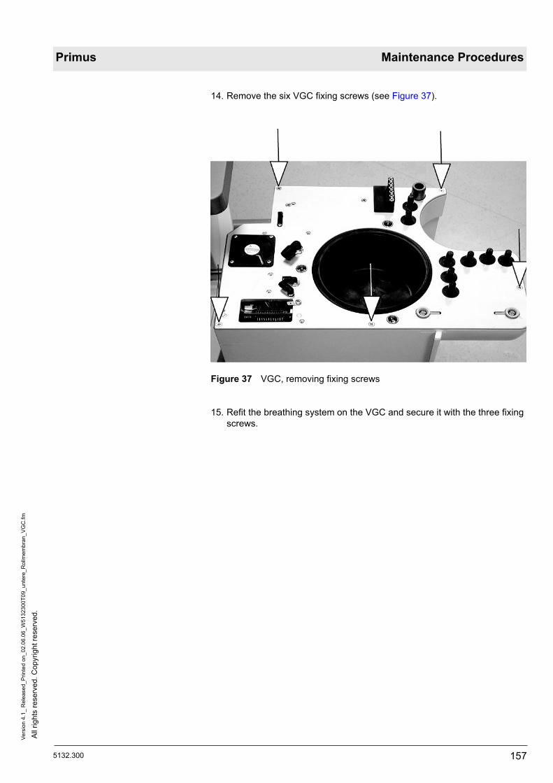
5132.300
All
right
s re
serv
ed. C
opyr
ight
rese
rved
.Ve
rsio
n 4.
1_ R
elea
sed_
Prin
ted
on_0
2.06
.06_
W51
3230
0T09
_unt
ere_
Rol
lmem
bran
_VG
C.fm
157
Primus Maintenance Procedures
14. Remove the six VGC fixing screws (see Figure 37).
Figure 37 VGC, removing fixing screws
15. Refit the breathing system on the VGC and secure it with the three fixing screws.

All
right
s re
serv
ed. C
opyr
ight
rese
rved
.Ve
rsio
n 4.
1_ R
elea
sed_
Prin
ted
on_0
2.06
.06_
W51
3230
0T09
_unt
ere_
Rol
lmem
bran
_VG
C.fm
158 5132.300
Maintenance Procedures Primus
16. Lift the VGC together with the breathing system (total weight approx. 15 kg) vertically out of the VGC housing (see Figure 38).
Figure 38 Taking VGC out of housing
17. Place the VGC on a static-dissipative mat.
18. Slacken the three fixing screws for the breathing system and remove the breathing system from the VGC.
11.2 Removing the pis-ton-cylinder unit
CAUTIONElectrostatic discharge!Electrostatic discharge may damage electrostatic sensitive devices. When handling electrostatic sensitive devices use a static-dissipative mat and a wrist strap.
CAUTIONPossible damage to the perforated disk of the incremental encoder (piston-cylinder unit)!The perforated disk of the incremental encoder is deformed even by slight mechanical pressure (for location see Figure 39).Exercise great care when reaching into the opening above the perforated disk.

5132.300
All
right
s re
serv
ed. C
opyr
ight
rese
rved
.Ve
rsio
n 4.
1_ R
elea
sed_
Prin
ted
on_0
2.06
.06_
W51
3230
0T09
_unt
ere_
Rol
lmem
bran
_VG
C.fm
159
Primus Maintenance Procedures
Figure 39 VGC, position of incremental encoder perforated disk
1. Place the VGC upside down on the static-dissipative mat.2. Remove the fixing screw of the PCB unit (see Figure 40).
Figure 40 VGC, PCB unit fixing screw
3. Swivel the PCB unit aside to the left.

All
right
s re
serv
ed. C
opyr
ight
rese
rved
.Ve
rsio
n 4.
1_ R
elea
sed_
Prin
ted
on_0
2.06
.06_
W51
3230
0T09
_unt
ere_
Rol
lmem
bran
_VG
C.fm
160 5132.300
Maintenance Procedures Primus
4. Unplug the three electrical connectors of the piston-cylinder unit (see Fig-ure 41).
Figure 41 ANALOG PRIMUS PCB, connections to the piston-cylinder unit
5. Remove the four piston-cylinder unit fixing screws (see Figure 42 and Figure 43).
Figure 42 Piston-cylinder unit, fixing screws (1)

5132.300
All
right
s re
serv
ed. C
opyr
ight
rese
rved
.Ve
rsio
n 4.
1_ R
elea
sed_
Prin
ted
on_0
2.06
.06_
W51
3230
0T09
_unt
ere_
Rol
lmem
bran
_VG
C.fm
161
Primus Maintenance Procedures
Figure 43 Piston-cylinder unit, fixing screws (2)
6. Place the motor section of the piston-cylinder unit upside down on a suit-able surface.

All
right
s re
serv
ed. C
opyr
ight
rese
rved
.Ve
rsio
n 4.
1_ R
elea
sed_
Prin
ted
on_0
2.06
.06_
W51
3230
0T09
_unt
ere_
Rol
lmem
bran
_VG
C.fm
162 5132.300
Maintenance Procedures Primus
11.2.1 Removing/Fitting the lower rolling seal
1. Remove the three fixing screws from the cylinder of the rolling seal (see Figure 44).
Figure 44 Piston-cylinder unit, cylinder fixing screws

5132.300
All
right
s re
serv
ed. C
opyr
ight
rese
rved
.Ve
rsio
n 4.
1_ R
elea
sed_
Prin
ted
on_0
2.06
.06_
W51
3230
0T09
_unt
ere_
Rol
lmem
bran
_VG
C.fm
163
Primus Maintenance Procedures
2. Lift the cylinder upwards out of the piston-cylinder unit (see Figure 45).
Figure 45 Piston-cylinder unit, removing cylinder

All
right
s re
serv
ed. C
opyr
ight
rese
rved
.Ve
rsio
n 4.
1_ R
elea
sed_
Prin
ted
on_0
2.06
.06_
W51
3230
0T09
_unt
ere_
Rol
lmem
bran
_VG
C.fm
164 5132.300
Maintenance Procedures Primus
The lower rolling seal (subsequently referred to as the rolling seal for short) is attached to the cylinder by the snap ring (A) and the O-ring (B) (see Figure 46).
Figure 46 Piston-cylinder unit, snap ring (A) and O-ring (B)

5132.300
All
right
s re
serv
ed. C
opyr
ight
rese
rved
.Ve
rsio
n 4.
1_ R
elea
sed_
Prin
ted
on_0
2.06
.06_
W51
3230
0T09
_unt
ere_
Rol
lmem
bran
_VG
C.fm
165
Primus Maintenance Procedures
3. Remove the snap ring and the O-ring (see Figure 47 and Figure 48).
Figure 47 Piston-cylinder unit, removing the snap ring
Figure 48 Piston-cylinder unit, removing the O-ring

All
right
s re
serv
ed. C
opyr
ight
rese
rved
.Ve
rsio
n 4.
1_ R
elea
sed_
Prin
ted
on_0
2.06
.06_
W51
3230
0T09
_unt
ere_
Rol
lmem
bran
_VG
C.fm
166 5132.300
Maintenance Procedures Primus
Figure 49 Piston-cylinder unit, incorrect installation of the rolling seal
4. Fold the rolling seal over the cylinder such that a narrow bulge is created under the snap ring groove (see Figure 50).
Figure 50 Piston-cylinder unit, folding rolling seal correctly
CAUTIONFaulty rolling seal due to incorrect installation!The rolling seal can be fitted the wrong way round. If it is, however, a wide bulge occurs under the snap ring (see Figure 49).To avoid errors, follow the instructions below precisely and compare the illustrations against the result achieved.
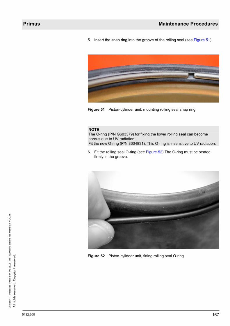
5132.300
All
right
s re
serv
ed. C
opyr
ight
rese
rved
.Ve
rsio
n 4.
1_ R
elea
sed_
Prin
ted
on_0
2.06
.06_
W51
3230
0T09
_unt
ere_
Rol
lmem
bran
_VG
C.fm
167
Primus Maintenance Procedures
5. Insert the snap ring into the groove of the rolling seal (see Figure 51).
Figure 51 Piston-cylinder unit, mounting rolling seal snap ring
6. Fit the rolling seal O-ring (see Figure 52) The O-ring must be seated firmly in the groove.
Figure 52 Piston-cylinder unit, fitting rolling seal O-ring
NOTEThe O-ring (P/N G603379) for fixing the lower rolling seal can become porous due to UV radiation.Fit the new O-ring (P/N 8604831). This O-ring is insensitive to UV radiation.
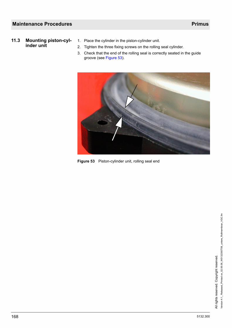
All
right
s re
serv
ed. C
opyr
ight
rese
rved
.Ve
rsio
n 4.
1_ R
elea
sed_
Prin
ted
on_0
2.06
.06_
W51
3230
0T09
_unt
ere_
Rol
lmem
bran
_VG
C.fm
168 5132.300
Maintenance Procedures Primus
11.3 Mounting piston-cyl-inder unit
1. Place the cylinder in the piston-cylinder unit.2. Tighten the three fixing screws on the rolling seal cylinder.3. Check that the end of the rolling seal is correctly seated in the guide
groove (see Figure 53).
Figure 53 Piston-cylinder unit, rolling seal end
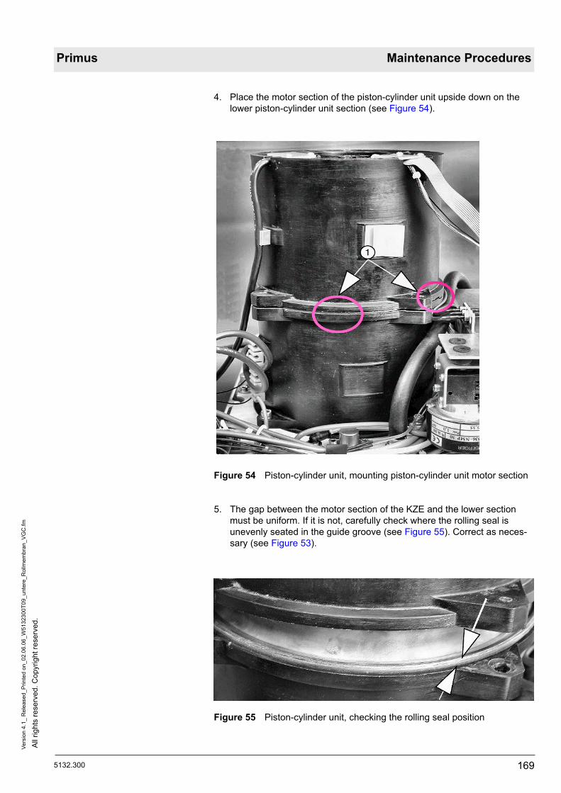
5132.300
All
right
s re
serv
ed. C
opyr
ight
rese
rved
.Ve
rsio
n 4.
1_ R
elea
sed_
Prin
ted
on_0
2.06
.06_
W51
3230
0T09
_unt
ere_
Rol
lmem
bran
_VG
C.fm
169
Primus Maintenance Procedures
4. Place the motor section of the piston-cylinder unit upside down on the lower piston-cylinder unit section (see Figure 54).
Figure 54 Piston-cylinder unit, mounting piston-cylinder unit motor section
5. The gap between the motor section of the KZE and the lower section must be uniform. If it is not, carefully check where the rolling seal is unevenly seated in the guide groove (see Figure 55). Correct as neces-sary (see Figure 53).
Figure 55 Piston-cylinder unit, checking the rolling seal position

All
right
s re
serv
ed. C
opyr
ight
rese
rved
.Ve
rsio
n 4.
1_ R
elea
sed_
Prin
ted
on_0
2.06
.06_
W51
3230
0T09
_unt
ere_
Rol
lmem
bran
_VG
C.fm
170 5132.300
Maintenance Procedures Primus
6. Screw in the four piston-cylinder unit fixing screws.7. Insert the piston-cylinder unit cables and the pneumatic system tube in
the cable holders (see Figure 56).
Figure 56 VGC, cable routing 1
8. Connect the three piston-cylinder unit cables with the ANALOG PRIMUS PCB (see Figure 57).
Figure 57 ANALOG PRIMUS PCB, connections to the piston-cylinder unit

5132.300
All
right
s re
serv
ed. C
opyr
ight
rese
rved
.Ve
rsio
n 4.
1_ R
elea
sed_
Prin
ted
on_0
2.06
.06_
W51
3230
0T09
_unt
ere_
Rol
lmem
bran
_VG
C.fm
171
Primus Maintenance Procedures
9. Lift the PCB unit. Make sure no tubes are bent or cables trapped as you do so.
10. Tighten the PCB unit fixing screw (see Figure 58).
Figure 58 VGC, PCB unit fixing screw

All
right
s re
serv
ed. C
opyr
ight
rese
rved
.Ve
rsio
n 4.
1_ R
elea
sed_
Prin
ted
on_0
2.06
.06_
W51
3230
0T09
_unt
ere_
Rol
lmem
bran
_VG
C.fm
172 5132.300
Maintenance Procedures Primus
11. Push the piston-cylinder unit cables into the holders according to the labelling on the cylinder (see Figure 59).
Figure 59 VGC, cable routing 2
12. Refit the VGC in the reverse order of its removal (see 11.1 Removing the VGC).
13. Carry out functional and electrical safety tests.
NOTEPossible leakages during the RV2 leak test!
To avoid leakages, secure the three fixing screws (cylinder of rolling seal, see Figure 44) with silicone glue at the at the screw seats.

5132.300
All
right
s re
serv
ed. C
opyr
ight
rese
rved
.Ve
rsio
n 2.
1_ R
elea
sed_
Prin
ted
on_0
2.06
.06_
W51
3230
0T12
_ZV-
Dru
ckm
inde
rer A
usta
usch
.fm
173
Primus Maintenance Procedures
12 Replacing pressure regulators PRPN2O, PRPAIR, PRPO2
12.1 Removing gas inlet block pressure regu-lators
The following steps can be carried out with the mixer fitted.
1. Follow the safety instructions (see Safety precautions document).2. Remove the compressed gas supply tubing.3. Take off the housing cover as necessary (see document: Removing hous-
ing cover).4. Remove the mixer cover.
Looking from above into the mixer, you will see the three pressure regulators (for assignment of gases see Figure 60).
Figure 60 Pressure regulator positions

All
right
s re
serv
ed. C
opyr
ight
rese
rved
.Ve
rsio
n 2.
1_ R
elea
sed_
Prin
ted
on_0
2.06
.06_
W51
3230
0T12
_ZV-
Dru
ckm
inde
rer A
usta
usch
.fm
174 5132.300
Maintenance Procedures Primus
5. Remove the hexagon socket fixing screws of the relevant pressure regu-lator (for position see Figure 61).
Figure 61 Pressure regulator fixing screws
12.2 Fitting pressure reg-ulators
In the following, fitting of the PRPN2O pressure regulator is shown as an example. The steps also apply correspondingly to the PRPAIR and PRPO2 pressure regulators.
CAUTIONMalfunction resulting from fitting error!On each pressure regulator is a label indicating the direction of flow (for example of pressure regulator for N2O see Figure 62). If the label is miss-ing, the direction of flow is indicated on the underside of the pressure regu-lator (see Figure 63).The preferential direction of the individual pressure regulators is embossed into the gas inlet block.When fitting, pay attention to the preferential direction of the pressure regu-lators.

5132.300
All
right
s re
serv
ed. C
opyr
ight
rese
rved
.Ve
rsio
n 2.
1_ R
elea
sed_
Prin
ted
on_0
2.06
.06_
W51
3230
0T12
_ZV-
Dru
ckm
inde
rer A
usta
usch
.fm
175
Primus Maintenance Procedures
Figure 62 Preferential direction of N2O pressure regulator 'PRPN2O“ with label
Figure 63 Preferential direction of N2O pressure regulator 'PRPN2O“ with-out label

All
right
s re
serv
ed. C
opyr
ight
rese
rved
.Ve
rsio
n 2.
1_ R
elea
sed_
Prin
ted
on_0
2.06
.06_
W51
3230
0T12
_ZV-
Dru
ckm
inde
rer A
usta
usch
.fm
176 5132.300
Maintenance Procedures Primus
Figure 64 Fixed locking cap
1. Pull locking cap upwards and unlock (A). This creates a gap (B) between the housing and the locking cap (see Figure 65). The pressure regulator can now be adjusted.
Figure 65 Unlocked locking cap
NOTEThe locking caps of the new pressure regulators are fixed in place (see Fig-ure 64). Unlock the caps prior to fitting.

5132.300
All
right
s re
serv
ed. C
opyr
ight
rese
rved
.Ve
rsio
n 2.
1_ R
elea
sed_
Prin
ted
on_0
2.06
.06_
W51
3230
0T12
_ZV-
Dru
ckm
inde
rer A
usta
usch
.fm
177
Primus Maintenance Procedures
2. Check that the two O-rings are fitted on the pressure regulator (see Fig-ure 66).
Figure 66 O-rings on pressure regulator 'PRPN2O“
3. Fit the pressure regulators in their respective preferential directions (see Figure 67).
Figure 67 Preferential directions of pressure regulators

All
right
s re
serv
ed. C
opyr
ight
rese
rved
.Ve
rsio
n 2.
1_ R
elea
sed_
Prin
ted
on_0
2.06
.06_
W51
3230
0T12
_ZV-
Dru
ckm
inde
rer A
usta
usch
.fm
178 5132.300
Maintenance Procedures Primus

5132.300
All
right
s re
serv
ed. C
opyr
ight
rese
rved
.Ve
rsio
n 3.
1_ R
elea
sed_
Prin
ted
on_0
2.06
.06_
W51
3230
0T13
_LiB
atte
rie_L
P_M
isch
er.fm
179
Primus Maintenance Procedures
13 Replacing CPU PRIMUS PCB lithium battery
13.1 Removing mixer 1. Follow the safety instructions (see document: Safety Precautions ).2. Remove the rear panel (see document: Removing rear panel).3. Remove the compressed gas supply tubing as necessary.4. Remove the three central gas supply tubes (see Figure 68).
Figure 68 Central gas supply hoses
NOTEBefore you replace the CPU PRIMUS PCB lithium battery, please note:Replacement as a maintenance procedure is only required up to software version 1.01.The lithium battery is no longer needed in software versions 1.05 or higher (and must always be removed).
NOTEBatteries are special waste.Dispose of the batteries in accordance with local waste disposal regula-tions.

All
right
s re
serv
ed. C
opyr
ight
rese
rved
.Ve
rsio
n 3.
1_ R
elea
sed_
Prin
ted
on_0
2.06
.06_
W51
3230
0T13
_LiB
atte
rie_L
P_M
isch
er.fm
180 5132.300
Maintenance Procedures Primus
5. Remove the fixing screw from the gas inlet block using an Allen key (see Figure 69).
Figure 69 Fixing screw on gas inlet block
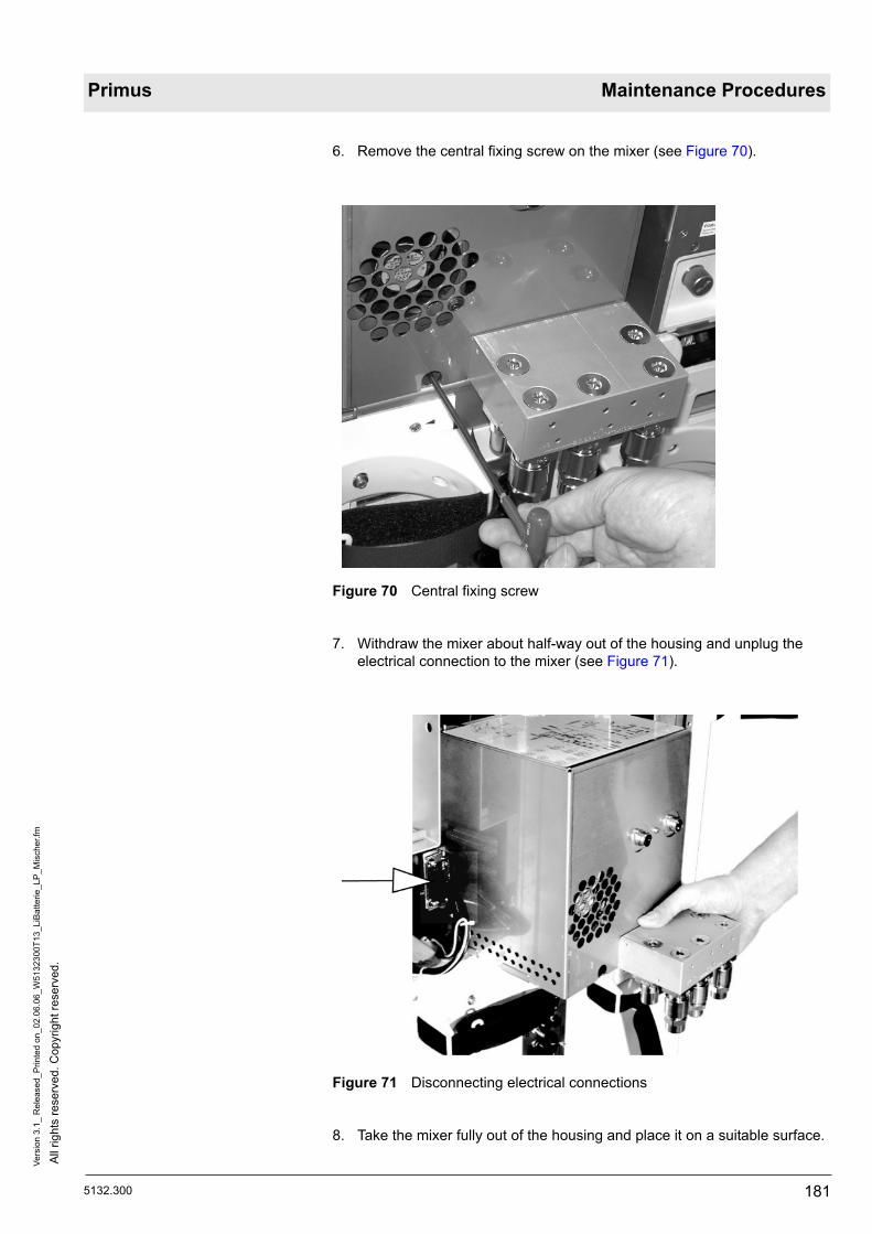
5132.300
All
right
s re
serv
ed. C
opyr
ight
rese
rved
.Ve
rsio
n 3.
1_ R
elea
sed_
Prin
ted
on_0
2.06
.06_
W51
3230
0T13
_LiB
atte
rie_L
P_M
isch
er.fm
181
Primus Maintenance Procedures
6. Remove the central fixing screw on the mixer (see Figure 70).
Figure 70 Central fixing screw
7. Withdraw the mixer about half-way out of the housing and unplug the electrical connection to the mixer (see Figure 71).
Figure 71 Disconnecting electrical connections
8. Take the mixer fully out of the housing and place it on a suitable surface.

All
right
s re
serv
ed. C
opyr
ight
rese
rved
.Ve
rsio
n 3.
1_ R
elea
sed_
Prin
ted
on_0
2.06
.06_
W51
3230
0T13
_LiB
atte
rie_L
P_M
isch
er.fm
182 5132.300
Maintenance Procedures Primus
13.2 Removing mixer cover
1. Follow the safety instructions (see document: Safety Precautions ).2. Remove the compressed gas supply tubing as necessary.3. Remove the three mixer cover fixing screws (see Figure 72).
Figure 72 Mixer cover fixing screws
4. Remove the mixer cover.

5132.300
All
right
s re
serv
ed. C
opyr
ight
rese
rved
.Ve
rsio
n 3.
1_ R
elea
sed_
Prin
ted
on_0
2.06
.06_
W51
3230
0T13
_LiB
atte
rie_L
P_M
isch
er.fm
183
Primus Maintenance Procedures
13.3 Replacing the lith-ium battery
Figure 73 Location of the lithium battery on the CPU PRIMUS PCB
1. Pry the lithium battery off the holder using an appropriate tool (see Figure 74).
Figure 74 Removing the lithium battery

All
right
s re
serv
ed. C
opyr
ight
rese
rved
.Ve
rsio
n 3.
1_ R
elea
sed_
Prin
ted
on_0
2.06
.06_
W51
3230
0T13
_LiB
atte
rie_L
P_M
isch
er.fm
184 5132.300
Maintenance Procedures Primus
2. Place the new lithium battery into the holder (positive terminal up) and click into the clamps without using too much force.
13.4 Fitting mixer cover
1. Refit the mixer cover in the reverse order of its removal.2. Fit the mixer (see section 13.5 Mixer fitting).
13.5 Mixer fitting 1. Before fitting the mixer, check that the six terminal block O-rings are fitted in the housing (see Figure 75).
Figure 75 Six O-rings on connector block
2. Refit the mixer in the reverse order of its removal (see 13.1 Removing mixer ).
3. Carry out functional and electrical safety tests.
NOTEBatteries are special waste.Dispose of the batteries in accordance with local waste disposal regula-tions.
CAUTIONDamage to cables by trapping!Make sure no cables are trapped when refitting the mixer cover.

5132.300
All
right
s re
serv
ed. C
opyr
ight
rese
rved
.Ve
rsio
n 2.
0_ R
elea
sed_
Prin
ted
on_0
2.06
.06_
W51
3230
0T15
_PE
EP_
MA
N_S
PO
NT_
Mem
bran
.fm
185
Primus Maintenance Procedures
14 Replacing PEEP dia-phragm and MAN/SPONT dia-phragm
1. Follow the safety instructions (see document: Safety precautions).2. Remove the absorber cup.3. Slacken the five screws on the compact breathing system cover (see Fig-
ure 76).
Figure 76 Compact breathing system cover
4. Lift the compact breathing system cover and place it on a suitable sur-face.
Underneath the valve block (Figure 77/1) are the diaphragm sets of the PEEP valve V1 (Figure 77/2) and the MAN/SPONT switching valve V2 (Figure 77/3).
Figure 77 Valve block (1)

All
right
s re
serv
ed. C
opyr
ight
rese
rved
.Ve
rsio
n 2.
0_ R
elea
sed_
Prin
ted
on_0
2.06
.06_
W51
3230
0T15
_PE
EP_
MA
N_S
PO
NT_
Mem
bran
.fm
186 5132.300
Maintenance Procedures Primus
5. Turn the valve plate round and remove the four valve block fixing screws (see Figure 78).
Figure 78 Valve block fixing screws
6. Replace the following components: the diaphragm connector of the PEEP valve V1 (Figure 79/1), the O-rings (Figure 79/2) and the diaphragm set of the MAN/SPONT switching valve V2 (Figure 79/3) (see Figure 79).When assembling, make sure the metal ring of valve V1 and the springs of valve V2 are in place!
Figure 79 Positions of V1, V2 and O-rings
7. Screw in the four Phillips screws.8. Refit the valve block in the reverse order of its removal. Observe the fol-
lowing points: After fitting the valve block, valves V1 and V2 must be moveable by fingers. The spring effect of V2 must be perceptible.

5132.300
All
right
s re
serv
ed. C
opyr
ight
rese
rved
.Ve
rsio
n 2.
0_ R
elea
sed_
Prin
ted
on_0
2.06
.06_
W51
3230
0T15
_PE
EP_
MA
N_S
PO
NT_
Mem
bran
.fm
187
Primus Maintenance Procedures
The following test steps are carried out with a ventilation dummy:9. Carry out the Primus power-on test.10. Carry out a MAN/SPONT ventilation.11. Carry out an IPPV ventilation with pre-set “PEEP” of 10 hPa.12. Check the flow and pressure parameters.

All
right
s re
serv
ed. C
opyr
ight
rese
rved
.Ve
rsio
n 2.
0_ R
elea
sed_
Prin
ted
on_0
2.06
.06_
W51
3230
0T15
_PE
EP_
MA
N_S
PO
NT_
Mem
bran
.fm
188 5132.300
Maintenance Procedures Primus

5132.300
All
right
s re
serv
ed. C
opyr
ight
rese
rved
.Ve
rsio
n 3.
1_ R
elea
sed_
Prin
ted
on_0
2.06
.06_
W51
3230
0T16
_Hoc
hdru
ckre
gler
_Fla
sche
n.fm
189
Primus Maintenance Procedures
15 Pressure regulator major overhaul
15.1 Safety precautionsWARNINGExplosion and fire hazard!Always make sure parts which come into contact with oxygen are free of grease and oil prior to fitting.
CAUTIONRisk of damage to Primus if pressure regulator and blow-off valve are adjusted incorrectly.The pressure regulator and its blow-off valve must be readjusted after a major overhaul. For safety reasons, it is recommended to have the adjust-ment done by DrägerService.

All
right
s re
serv
ed. C
opyr
ight
rese
rved
.Ve
rsio
n 3.
1_ R
elea
sed_
Prin
ted
on_0
2.06
.06_
W51
3230
0T16
_Hoc
hdru
ckre
gler
_Fla
sche
n.fm
190 5132.300
Maintenance Procedures Primus
15.2 Required spare parts
Figure 80 Major overhaul spare parts set, see legend
Table 1 Legend to Figure 80
Name Part number
General overhaul spare parts set MX08047
Set of gas type labels MX08060
Item Designation
1 Closing plunger (blow-off valve)
2 Friction (valve tappet)
3 Sealing (valve tappet)
4 Diaphram on diaphragm carrier

5132.300
All
right
s re
serv
ed. C
opyr
ight
rese
rved
.Ve
rsio
n 3.
1_ R
elea
sed_
Prin
ted
on_0
2.06
.06_
W51
3230
0T16
_Hoc
hdru
ckre
gler
_Fla
sche
n.fm
191
Primus Maintenance Procedures
15.3 Service Equipment Required
Figure 81 Tools; for legend, see the following table
Table 2 Legend to Figure 81
Item Name Part no.
1 Torque spanner 7910132
2 Square bit, 1/2 inch. 7901864
3 Pin insert (Note: Tool was modified mid-2004. The pins have now a length of 5 mm instead of 3 mm. Perform the general overhaul using the new tool only!).
7901129
4 Loctite 221 (not shown). 7901966
6 Loctite 271 (not shown). 1198165

All
right
s re
serv
ed. C
opyr
ight
rese
rved
.Ve
rsio
n 3.
1_ R
elea
sed_
Prin
ted
on_0
2.06
.06_
W51
3230
0T16
_Hoc
hdru
ckre
gler
_Fla
sche
n.fm
192 5132.300
Maintenance Procedures Primus
Figure 82 Wrench; for legend, see the following table
Table 3 Legend to Figure 82
15.4 Removing the pres-sure regulator
In the following section an O2 pressure regulator is used as an example for a major overhaul.
Item Name Part no.
1 Wrench (blow-off valve) 7911318
WARNINGRisk of personal injury due to improper setting up of high-pressure cylinders!The high-pressure cylinders used shall be set up securely (to prevent them from being knocked over) in accordance with applicable safety regulations.
WARNINGRisk of personal injury due to improper disassembly of the pressure regulator!If the high-pressure regulator is fitted on a high-pressure cylinder, always vent the high-pressure of the high-pressure cylinder first before performing the following work steps.During the entire major overhaul procedure, protect the high-pres-sure cylinder valve from being opened unintentionally.

5132.300
All
right
s re
serv
ed. C
opyr
ight
rese
rved
.Ve
rsio
n 3.
1_ R
elea
sed_
Prin
ted
on_0
2.06
.06_
W51
3230
0T16
_Hoc
hdru
ckre
gler
_Fla
sche
n.fm
193
Primus Maintenance Procedures
1. Leave the pressure regulator fitted on the high-pressure cylinder or place it flat on an appropriate surface.
2. Remove the gas-type label (Figure 83/1).
Figure 83 Gas-type label
3. Remove the front housing part of the pressure regulator (Figure 84/1).While doing so, the pressure regulator should be fitted on the high-pres-sure cylinder or on an assembly aid, or should be placed flat on an appro-priate surface.
Figure 84 Removing the front housing part

All
right
s re
serv
ed. C
opyr
ight
rese
rved
.Ve
rsio
n 3.
1_ R
elea
sed_
Prin
ted
on_0
2.06
.06_
W51
3230
0T16
_Hoc
hdru
ckre
gler
_Fla
sche
n.fm
194 5132.300
Maintenance Procedures Primus
15.5 Replacing the “Major Overhaul” spare parts set
1. Remove the diaphragm carrier (Figure 85/1).
Figure 85 Housing (open)
2. Remove the fixing nut (Figure 86/1) from the diaphragm carrier.
Figure 86 Diaphragm carrier with fixing nut
WARNINGExplosion and fire hazard!Always make sure parts which come into contact with oxygen are free of grease and oil prior to fitting.

5132.300
All
right
s re
serv
ed. C
opyr
ight
rese
rved
.Ve
rsio
n 3.
1_ R
elea
sed_
Prin
ted
on_0
2.06
.06_
W51
3230
0T16
_Hoc
hdru
ckre
gler
_Fla
sche
n.fm
195
Primus Maintenance Procedures
3. Fit the new diaphragm and secure the nut with Loctite 221. Tighten the nut (Figure 86/1) only such that the diaphragm is not deformed. Fit the ring (Figure 87/1) with its radius side facing the diaphragm.
Figure 87 Fitting position of the ring

All
right
s re
serv
ed. C
opyr
ight
rese
rved
.Ve
rsio
n 3.
1_ R
elea
sed_
Prin
ted
on_0
2.06
.06_
W51
3230
0T16
_Hoc
hdru
ckre
gler
_Fla
sche
n.fm
196 5132.300
Maintenance Procedures Primus
4. Place the diaphragm carrier into the housing. Make sure that the compo-nents under the diaphragm are fitted in the correct order (see Figure 88).
Figure 88 Components under the diaphragm
Table 4 Legend to Figure 88
Item Designation
1 Diaphragm
2 Ring
3 Diaphragm carrier
4 Control spring
5 Pressure plate
6 Adjusting screw

5132.300
All
right
s re
serv
ed. C
opyr
ight
rese
rved
.Ve
rsio
n 3.
1_ R
elea
sed_
Prin
ted
on_0
2.06
.06_
W51
3230
0T16
_Hoc
hdru
ckre
gler
_Fla
sche
n.fm
197
Primus Maintenance Procedures
5. Using an appropriate tool (bit with 11 mm WAF), unscrew the brass valve seat (Figure 89/1).
Figure 89 Valve seat

All
right
s re
serv
ed. C
opyr
ight
rese
rved
.Ve
rsio
n 3.
1_ R
elea
sed_
Prin
ted
on_0
2.06
.06_
W51
3230
0T16
_Hoc
hdru
ckre
gler
_Fla
sche
n.fm
198 5132.300
Maintenance Procedures Primus
6. Remove the friction (Figure 90/1) from the valve plunger (Figure 90/2)and replace it with a new one.
7. Remove the sealing (Figure 90/3) from the valve seat and replace it with a new one.
Figure 90 Valve components
8. Fit the valve components. Place the new sealing such that the internal chamfer (Figure 90/3) points toward the valve plunger. Tighten the valve seat (to a torque of 5 Nm).
9. Refit the housing in the reverse order of its removal.
NOTEAvoid any contamination during the next work steps.

5132.300
All
right
s re
serv
ed. C
opyr
ight
rese
rved
.Ve
rsio
n 3.
1_ R
elea
sed_
Prin
ted
on_0
2.06
.06_
W51
3230
0T16
_Hoc
hdru
ckre
gler
_Fla
sche
n.fm
199
Primus Maintenance Procedures
10. Secure the thread of the housing. To do so, fill a small amount of Loctite 270 (1198165) into the small housing borehole (Figure 91/1).
Figure 91 Small housing borehole
11. Remove the blow-off valve using the wrench (Figure 92/1).
Figure 92 Removing the blow-off valve

All
right
s re
serv
ed. C
opyr
ight
rese
rved
.Ve
rsio
n 3.
1_ R
elea
sed_
Prin
ted
on_0
2.06
.06_
W51
3230
0T16
_Hoc
hdru
ckre
gler
_Fla
sche
n.fm
200 5132.300
Maintenance Procedures Primus
12. Remove the blow-off valve's components and replace the closing plunger (Figure 93/3).
Figure 93 Blow-off valve components
Table 5 Legend to Figure 88
13. Refit the blow-off valve in the reverse order of its removal. Screw in the adjusting screw without using excessive force.
14. For safety reasons, it is recommended to have the downstream pressure and the blow-off valve adjusted by DrägerService.
Item Designation
1 Adjusting screw
2 Control spring
3 Closing plunger

201
Schematics and Diagrams

202

Primus Schematics and Diagrams
5132.300 203
All
right
s re
serv
ed. C
opyr
ight
rese
rved
.Ve
rsio
n 2.
0_ R
elea
sed_
Prin
ted
on_0
2.06
.06_
S51
3230
0T01
_Pne
umat
ikpl
an_P
rimus
.fm
1Pr
imus
pne
umat
ic c
ompo
nent
s di
agra
m
Figu
re 1
Prim
us p
neum
atic
com
pone
nts
diag
ram
as
of s
oftw
are
2.n,
see
lege
nd T
able
1 (c
hang
es s
ee (X
))
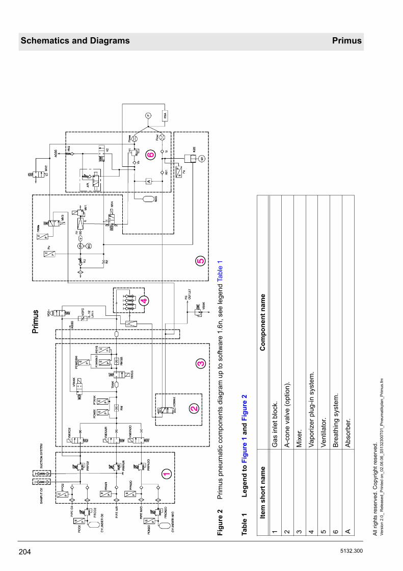
Schematics and Diagrams Primus
204 5132.300
All r
ight
s re
serv
ed. C
opyr
ight
rese
rved
.Ve
rsio
n 2.
0_ R
elea
sed_
Prin
ted
on_0
2.06
.06_
S51
3230
0T01
_Pne
umat
ikpl
an_P
rimus
.fm
Figu
re 2
Prim
us p
neum
atic
com
pone
nts
diag
ram
up
to s
oftw
are
1.6n
, see
lege
nd T
able
1
Tabl
e 1
Lege
nd to
Fig
ure
1 an
d Fi
gure
2
Item
sho
rt n
ame
Com
pone
nt n
ame
1G
as in
let b
lock
.
2A
-con
e va
lve
(opt
ion)
.
3M
ixer
.
4Va
poriz
er p
lug-
in s
yste
m.
5Ve
ntila
tor.
6B
reat
hing
sys
tem
.
AA
bsor
ber.

Primus Schematics and Diagrams
5132.300 205
All
right
s re
serv
ed. C
opyr
ight
rese
rved
.Ve
rsio
n 2.
0_ R
elea
sed_
Prin
ted
on_0
2.06
.06_
S51
3230
0T01
_Pne
umat
ikpl
an_P
rimus
.fm
AG
SS
Ane
sthe
tic g
as s
cave
ngin
g sy
stem
.
AP
LA
PL
valv
e.
BA
GB
reat
hing
bag
.
CY
LIN
DE
R N
2ON
2O c
ompr
esse
d-ga
s cy
linde
r.
CY
LIN
DE
R O
2O
2 co
mpr
esse
d-ga
s cy
linde
r.
EE
ject
or.
FG O
UTL
ET
Fres
h ga
s ou
tlet
Flow
eE
xpira
tory
flow
sen
sor
Flow
iIn
spira
tory
flow
sen
sor.
IRIA
IRIA
(ane
sthe
tic g
as m
easu
rem
ent).
KZE
Pis
ton-
cylin
der u
nit.
M1
Pis
ton-
cylin
der u
nit m
otor
.
M2
Mot
or P
EE
P p
ress
ure.
MV
1P
EE
P/P
max
val
ve.
MV
2C
alib
ratio
n va
lve.
MV
3B
reat
hing
sys
tem
/fres
h-ga
s ou
tlet s
witc
hing
val
ve.
MV
4P
EE
P v
alve
/con
trol v
alve
.
PP
atie
nt.
PAW
eE
xpira
tory
airw
ay p
ress
ure
sens
or.
PC
N2O
N2O
com
pres
sed-
gas
cylin
der p
ress
ure.
PC
O2
O2
com
pres
sed-
gas
cylin
der p
ress
ure.
PD
MG
SH
ID
iffer
entia
l pre
ssur
e (h
igh
rang
e).
PD
MG
SLO
Diff
eren
tial p
ress
ure
(low
rang
e).
PD
MIX
Diff
eren
tial p
ress
ure
mix
er.
PD
TAN
KP
ress
ure
in th
e “T
AN
K”.
PIP
E A
IRA
IR c
entra
l sup
ply.
PIP
E N
2ON
2O c
entra
l sup
ply.
Item
sho
rt n
ame
Com
pone
nt n
ame

Schematics and Diagrams Primus
206 5132.300
All r
ight
s re
serv
ed. C
opyr
ight
rese
rved
.Ve
rsio
n 2.
0_ R
elea
sed_
Prin
ted
on_0
2.06
.06_
S51
3230
0T01
_Pne
umat
ikpl
an_P
rimus
.fm
PIP
E O
2O
2 ce
ntra
l sup
ply.
PPA
IRA
IR c
entra
l sup
ply
pres
sure
.
PP
N2O
N
2O c
entra
l sup
ply
pres
sure
.
PP
O2
O2
cent
ral s
uppl
y pr
essu
re.
PR
CN
2ON
2O c
ompr
esse
d-ga
s cy
linde
r pre
ssur
e re
gula
tor.
PR
PAIR
AIR
cen
tral s
uppl
y pr
essu
re re
gula
tor.
PR
PN
2ON
2O c
entra
l sup
ply
pres
sure
regu
lato
r.
PR
PO
2O
2 ce
ntra
l sup
ply
pres
sure
regu
lato
r.
PS
YS
Sys
tem
pre
ssur
e.
Pu
Vacu
um p
ress
ure
sens
or, c
urre
nt v
acuu
m.
Pz
Insp
irato
ry a
irway
pre
ssur
e se
nsor
.
R1
Res
trict
or to
sm
ooth
pre
ssur
e pe
aks.
R2
Res
isto
r to
redu
ce v
acuu
m (p
ump
off).
RM
Fres
h-ga
s m
easu
ring
path
(ups
tream
of t
he T
AN
K).
RM
GS
Fres
h-ga
s m
easu
ring
path
.
RV
1N
on-r
etur
n va
lve
of fr
esh-
gas
deco
uplin
g.
RV
2A
GS
S n
on-r
etur
n va
lve.
RV
3K
ZE v
acuu
m n
on-r
etur
n va
lve
(as
from
sof
twar
e 2.
n).
SA
MP
LE O
2O
2 co
nnec
tion
for e
xter
nal O
2 flo
wm
eter
(opt
ion)
.
SU
CTI
ON
SY
STE
MC
onne
ctio
n fo
r ext
erna
l bro
nchi
al s
uctio
n de
vice
(opt
ion)
.
TAN
K
Fres
h-ga
s ta
nk.
VVo
lum
e.
V1
PE
EP
val
ve d
iaph
ragm
.
V2
Aut
o-m
an/s
pont
ON
/OFF
val
ve.
VB
AK
A-c
one
safe
ty v
alve
.
VeE
xpira
tory
val
ve.
Vi
Insp
irato
ry v
alve
.
Item
sho
rt n
ame
Com
pone
nt n
ame

Primus Schematics and Diagrams
5132.300 207
All
right
s re
serv
ed. C
opyr
ight
rese
rved
.Ve
rsio
n 2.
0_ R
elea
sed_
Prin
ted
on_0
2.06
.06_
S51
3230
0T01
_Pne
umat
ikpl
an_P
rimus
.fm
VM
GS
Fres
h-ga
s flo
w v
alve
(pro
porti
onal
val
ve).
VM
IXO
2O
2 m
ixer
val
ve.
VM
IXA
IRA
IR m
ixer
val
ve.
VM
IXN
2ON
2O m
ixer
val
ve.
VO
2+O
2 flu
sh v
alve
.
VP
Vacu
um p
ump.
VS
FCS
afet
y O
2 co
ntro
l.
VS
WA
KA
-con
e va
lve.
VTA
NK
TAN
K v
alve
(saf
ety
valv
e).
VU
Vacu
um v
alve
-200
mba
r.
Item
sho
rt n
ame
Com
pone
nt n
ame

Schematics and Diagrams Primus
208 5132.300
All r
ight
s re
serv
ed. C
opyr
ight
rese
rved
.Ve
rsio
n 2.
0_ R
elea
sed_
Prin
ted
on_0
2.06
.06_
S51
3230
0T01
_Pne
umat
ikpl
an_P
rimus
.fm

Primus Schematics and Diagrams
5132.300 209
All
right
s re
serv
ed. C
opyr
ight
rese
rved
.Ve
rsio
n 3.
0_ R
elea
sed_
Prin
ted
on_0
2.06
.06_
S51
3230
0T02
_Dia
gram
me_
Scha
ltpla
ene.
fm
2Sc
hem
atic
s an
d D
iagr
ams
Figu
re 3
Prim
us b
lock
dia
gram

Schematics and Diagrams Primus
210 5132.300
All r
ight
s re
serv
ed. C
opyr
ight
rese
rved
.Ve
rsio
n 3.
0_ R
elea
sed_
Prin
ted
on_0
2.06
.06_
S51
3230
0T02
_Dia
gram
me_
Sch
altp
laen
e.fm
Figu
re 4
Mix
er c
onne
ctio
n di
agra
m

Primus Schematics and Diagrams
5132.300 211
All
right
s re
serv
ed. C
opyr
ight
rese
rved
.Ve
rsio
n 3.
0_ R
elea
sed_
Prin
ted
on_0
2.06
.06_
S51
3230
0T02
_Dia
gram
me_
Scha
ltpla
ene.
fm
Figu
re 5
Prim
us tu
bing
dia
gram

Schematics and Diagrams Primus
212 5132.300
All r
ight
s re
serv
ed. C
opyr
ight
rese
rved
.Ve
rsio
n 3.
0_ R
elea
sed_
Prin
ted
on_0
2.06
.06_
S51
3230
0T02
_Dia
gram
me_
Sch
altp
laen
e.fm
Figu
re 6
VG
C tu
bing
con
figur
atio
n an
d el
ectri
cal c
onne
ctio
ns (w
ith R
V3)

Primus Schematics and Diagrams
5132.300 213
All
right
s re
serv
ed. C
opyr
ight
rese
rved
.Ve
rsio
n 3.
0_ R
elea
sed_
Prin
ted
on_0
2.06
.06_
S51
3230
0T02
_Dia
gram
me_
Scha
ltpla
ene.
fm
Figu
re 7
VG
C tu
bing
con
figur
atio
n an
d el
ectri
cal c
onne
ctio
ns (w
ithou
t RV
3)

Schematics and Diagrams Primus
214 5132.300
All r
ight
s re
serv
ed. C
opyr
ight
rese
rved
.Ve
rsio
n 3.
0_ R
elea
sed_
Prin
ted
on_0
2.06
.06_
S51
3230
0T02
_Dia
gram
me_
Sch
altp
laen
e.fm
Figu
re 8
PG
M b
lock
dia
gram

Primus Schematics and Diagrams
5132.300 215
All
right
s re
serv
ed. C
opyr
ight
rese
rved
.Ve
rsio
n 3.
0_ R
elea
sed_
Prin
ted
on_0
2.06
.06_
S51
3230
0T02
_Dia
gram
me_
Scha
ltpla
ene.
fm
Figu
re 9
Blo
ck d
iagr
am o
f the
PG
M2
with
Ser
vom
ex O
2 se
nsor

Schematics and Diagrams Primus
216 5132.300
All r
ight
s re
serv
ed. C
opyr
ight
rese
rved
.Ve
rsio
n 3.
0_ R
elea
sed_
Prin
ted
on_0
2.06
.06_
S51
3230
0T02
_Dia
gram
me_
Sch
altp
laen
e.fm
Figu
re 1
0 C
onne
ctio
n di
agra
m o
f the
PG
M2
with
Pat
o O
2 se
nsor
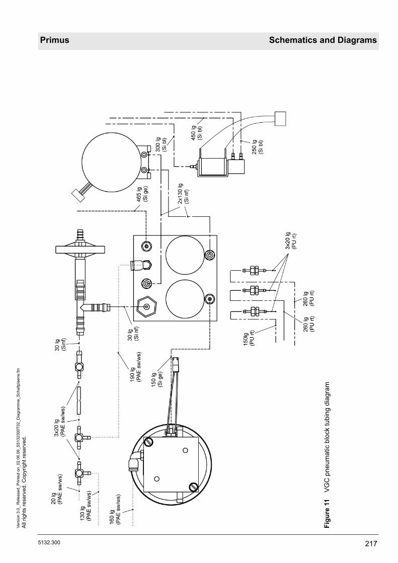
Primus Schematics and Diagrams
5132.300 217
All
right
s re
serv
ed. C
opyr
ight
rese
rved
.Ve
rsio
n 3.
0_ R
elea
sed_
Prin
ted
on_0
2.06
.06_
S51
3230
0T02
_Dia
gram
me_
Scha
ltpla
ene.
fm
Figu
re 1
1 V
GC
pne
umat
ic b
lock
tubi
ng d
iagr
am

Schematics and Diagrams Primus
218 5132.300
All r
ight
s re
serv
ed. C
opyr
ight
rese
rved
.Ve
rsio
n 3.
0_ R
elea
sed_
Prin
ted
on_0
2.06
.06_
S51
3230
0T02
_Dia
gram
me_
Sch
altp
laen
e.fm
Figu
re 1
2 V
GC
ass
embl
y pl
ate

Annex
Parts catalog
Test List
Technical Information


Parts catalog
Primus
Because you careEmergency Care - Perioperative Care - Critical Care - Perinatal Care - Home Care
5132.300
Revision: 2006-02-27 12:45:21
Because you care

2

Primus 3 annual Parts catalog
ItemNo. Part No. Description Qty. Qty.
unit Remark
2 8603057 Battery 2.000 St
4 2600650 DIAPHRAGM,CUP 1.000 St
5 6870910 FILTER MAT 1.000 St
6 8603144 FILTER MAT 1.000 St
7 8603301 FILTER MAT 1.000 St
8 8603662 FILTER MAT 1.000 St
9 U04314 O-RING SEAL 4.000 St
Revision: 2006-02-27 12:45:215132.300
Items that are shown in the illustration but are not listed below the illustration are not available as spare parts
3

Primus 1 annual Parts catalog
ItemNo. Part No. Description Qty. Qty.
unit Remark
1 8603662 FILTER MAT 1.000 St
2 6870910 FILTER MAT 1.000 St
3 8603301 FILTER MAT 1.000 St
4 8603144 FILTER MAT 1.000 St
5 U04314 O-RING SEAL 4.000 St
6 2600650 DIAPHRAGM,CUP 1.000 St
Revision: 2006-02-27 12:45:215132.300
Items that are shown in the illustration but are not listed below the illustration are not available as spare parts
4

Primus 2 annual Parts catalog
ItemNo. Part No. Description Qty. Qty.
unit Remark
2 8601238 NAFION HOSE 150 LG. 1.000 St
3 8603585 FILTER MAT 1.000 St
4 M19238 MESH BOTTOM 3.000 St
5 8603780 DIAPHRAGM 1.000 St
6 8603781 SEALING WASHER 1.000 St
7 M33275 DIAPHRAGM 1.000 St
8 R52382 O-RING SEAL 2.000 St
9 2600650 DIAPHRAGM,CUP 1.000 St
10 6870910 FILTER MAT 1.000 St
11 8603144 FILTER MAT 1.000 St
12 8603301 FILTER MAT 1.000 St
13 8603662 FILTER MAT 1.000 St
14 U04314 O-RING SEAL 4.000 St
Revision: 2006-02-27 12:45:215132.300
Items that are shown in the illustration but are not listed below the illustration are not available as spare parts
5

AGS system Parts catalog
ItemNo. Part No. Description Qty. Qty.
unit Remark
1 M33294 FILTER 1.000 St
Revision: 2006-02-27 12:45:215132.300
Items that are shown in the illustration but are not listed below the illustration are not available as spare parts
6

AGS system Canada Parts catalog
ItemNo. Part No. Description Qty. Qty.
unit Remark
M33294 FILTER 1.000 St
Revision: 2006-02-27 12:45:215132.300
Items that are shown in the illustration but are not listed below the illustration are not available as spare parts
7

Ejector type aspirator Parts catalog
ItemNo. Part No. Description Qty. Qty.
unit Remark
6723976 SET OF 5 BACTERIA FILT.(CH102) 1.000 St
CH00102 BACTERIA FILTERS 1.000 St for shut-offcash sucking off ejector
Revision: 2006-02-27 12:45:215132.300
Items that are shown in the illustration but are not listed below the illustration are not available as spare parts
8

PGM Primus Parts catalog
ItemNo. Part No. Description Qty. Qty.
unit Remark
6850930 O2-SENSOR-S 1.000 St
Revision: 2006-02-27 12:45:215132.300
Items that are shown in the illustration but are not listed below the illustration are not available as spare parts
9

RS SpO2 Parts catalog
ItemNo. Part No. Description Qty. Qty.
unit Remark
8603870 Upgrade kit Spo2 Primus 1.000 St
Revision: 2006-02-27 12:45:215132.300
Items that are shown in the illustration but are not listed below the illustration are not available as spare parts
10

Kit Parking holder Parts catalog
ItemNo. Part No. Description Qty. Qty.
unit Remark
1-8 M25102 SUPPORT FOR PARKING POSITION 1.000 St
Revision: 2006-02-27 12:45:215132.300
Items that are shown in the illustration but are not listed below the illustration are not available as spare parts
11

Accessories Suction Parts catalog
ItemNo. Part No. Description Qty. Qty.
unit Remark
M07582 SECRETION CONTROL GLASS 1.000 St
2M85594 RECEPTACLE 1.000 St
M25780 ASPIRATION HOSE 1.000 St
2M85012 CYLINDER CAP WITH VALVE 1.000 St
1203606 HOSE 5X2SI 60SHA NF M25779 1.000 m
2M19063 ANGULAR PORCELAIN BUSH 1.000 St
M30159 ANGULAR PORCELAIN BUSH 1.000 St
8601179 ACCESS.SUCTION UNIT F.JULIAN 1.000 St
Revision: 2006-02-27 12:45:215132.300
Items that are shown in the illustration but are not listed below the illustration are not available as spare parts
12

Accessories Julian Parts catalog
ItemNo. Part No. Description Qty. Qty.
unit Remark
8290286 Sample Line Set (10pcs) 10.000 St
M25647 NOZZLE 22/22 1.000 St
2166046 BREATH.HOSE 150CMLONG SLEEVE 1.000 St
2166038 BREATH.HOSE LONG 110CM SLEEVE 1.000 St
M33278 Y-PIECE ADULT,LUER LOCK 1.000 St
2166062 SILICON-BREATHING BAG 2,3 L 1.000 St
Revision: 2006-02-27 12:45:215132.300
Items that are shown in the illustration but are not listed below the illustration are not available as spare parts
13

Suction hoses Parts catalog
ItemNo. Part No. Description Qty. Qty.
unit Remark
1 M35015 AGS-SCAVANGER HOSE 0,5M 1.000 St
2 M33297 AGS-SCAVANGER HOSE 1,5M 1.000 St
3 M33298 AGS-SCAVANGER HOSE 3M 1.000 St
4 M33299 AGS-SCAVANGER HOSE 5M 1.000 St
Revision: 2006-02-27 12:45:215132.300
Items that are shown in the illustration but are not listed below the illustration are not available as spare parts
14

Plugs Parts catalog
ItemNo. Part No. Description Qty. Qty.
unit Remark
1 G60580 AGSS PROBE/STRAIGHT-TYPE1/ EN 1.000 St
2 G60495 AGSS ANGLE PROBE / TYPE 1 / EN 1.000 St
Revision: 2006-02-27 12:45:215132.300
Items that are shown in the illustration but are not listed below the illustration are not available as spare parts
15

Plugs Parts catalog
ItemNo. Part No. Description Qty. Qty.
unit Remark
3 G60440 ANAESTH.WASTE GAS PROBE 45 1.000 St
Revision: 2006-02-27 12:45:215132.300
Items that are shown in the illustration but are not listed below the illustration are not available as spare parts
16

Ejector type aspirat. NIST Air Parts catalog
ItemNo. Part No. Description Qty. Qty.
unit Remark
1-16 MK01420 Suction Ejector, NIST 1.000 St
9 MK00514 FILTER 1.000 St
Revision: 2006-02-27 12:45:215132.300
Items that are shown in the illustration but are not listed below the illustration are not available as spare parts
17
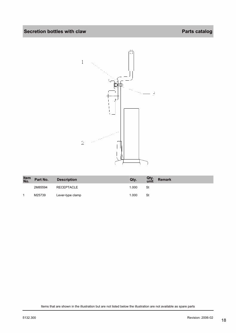
Secretion bottles with claw Parts catalog
ItemNo. Part No. Description Qty. Qty.
unit Remark
2M85594 RECEPTACLE 1.000 St
1 M25739 Lever-type clamp 1.000 St
Revision: 2006-02-27 12:45:215132.300
Items that are shown in the illustration but are not listed below the illustration are not available as spare parts
18

Pressure Reducer Parts catalog
ItemNo. Part No. Description Qty. Qty.
unit Remark
8603465 Press.Red.o2, DIN477-1,Primus 1.000 St
8603466 Press.Red.o2,PIN INDEX,Primus 1.000 St
8603706 Press.Red.o2,DIN477-1/6,Primus 1.000 St
8603707 Press.Red.o2,NF E29-650,Primus 1.000 St
8603718 Press.Red.Air,PIN IND.Primus 1.000 St
8603719 Press.Red.Air,DIN477-1,Primus 1.000 St
8603720 Press.Red.Air.NF E29-650,Prim 1.000 St
8603462 Press.Red.N2o,PIN IND.Primus 1.000 St
8603463 Press.Red.N2o,DIN477-1/11,Prim 1.000 St
8603464 Press.Red.N2o,DIN477-1/12,Prim 1.000 St
8603711 Press.Red.N2o,NF E29-650,Prim 1.000 St
Revision: 2006-02-27 12:45:215132.300
Items that are shown in the illustration but are not listed below the illustration are not available as spare parts
19

High Pressure Sensors Parts catalog
ItemNo. Part No. Description Qty. Qty.
unit Remark
8603316 HIGH PRESSURE SENSOR O2 1.000 St
8603520 HIGH PRESSURE SENSOR AIR 1.000 St
8603315 HIGH PRESSURE SENSOR N2O 1.000 St
Revision: 2006-02-27 12:45:215132.300
Items that are shown in the illustration but are not listed below the illustration are not available as spare parts
20

Pressure Gauges Parts catalog
ItemNo. Part No. Description Qty. Qty.
unit Remark
MX08048 PRESSURE GAUGE O2 1.000 St
MX08049 PRESSURE GAUGE AIR 1.000 St
MX08050 PRESSURE GAUGE N2O,CO2,XE 1.000 St
Revision: 2006-02-27 12:45:215132.300
Items that are shown in the illustration but are not listed below the illustration are not available as spare parts
21
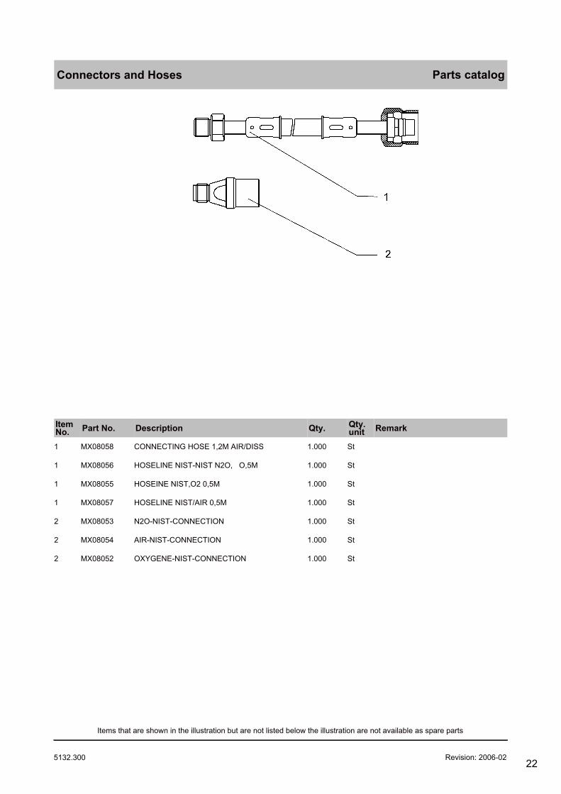
Connectors and Hoses Parts catalog
ItemNo. Part No. Description Qty. Qty.
unit Remark
1 MX08058 CONNECTING HOSE 1,2M AIR/DISS 1.000 St
1 MX08056 HOSELINE NIST-NIST N2O, O,5M 1.000 St
1 MX08055 HOSEINE NIST,O2 0,5M 1.000 St
1 MX08057 HOSELINE NIST/AIR 0,5M 1.000 St
2 MX08053 N2O-NIST-CONNECTION 1.000 St
2 MX08054 AIR-NIST-CONNECTION 1.000 St
2 MX08052 OXYGENE-NIST-CONNECTION 1.000 St
Revision: 2006-02-27 12:45:215132.300
Items that are shown in the illustration but are not listed below the illustration are not available as spare parts
22

Sets and Spare Parts Parts catalog
ItemNo. Part No. Description Qty. Qty.
unit Remark
4 D02316 MESH BOTTOM 1.000 St
5 MX08157 REP.SET GASKET/F ( FRANKREICH) 1.000 St
6 MX08158 REP.SET GASKET/C (USA) 1.000 St
7 MX08159 REP.SET GASKET/B (ENGLAND ) 1.000 St
8 MX08160 REP.SET GASKET/N (NIEDERLANDE) 1.000 St
10 MX08051 PROTECTING CAP 1.000 St
O.A MX08061 REP.SET GASKET 1.000 St Contents:MX08157,MX08158,MX08159,D02316,D43929
O.A. D20215 SET OF PACKING RINGS 1.000 St
Revision: 2006-02-27 12:45:215132.300
Items that are shown in the illustration but are not listed below the illustration are not available as spare parts
23

O2-Pressure reducer G3/4 Parts catalog
ItemNo. Part No. Description Qty. Qty.
unit Remark
AF00528 HIGH PRESSURE SENSOR O2 1.000 St
8603704 HIGH PRESSURE SENSOR O2 1.000 St
AF00529 PRESS.RED.+SENSOR O2 PIN INDEX 1.000 St
AF00530 PRESS.RED.+SENSOR N2O PIN IND. 1.000 St
8603709 HIGH PRESSURE SENSOR N2O 1.000 St
AF00532 HIGH PRESSURE SENSOR N2O 1.000 St
1-3,7-15 M34017 N2O-PRESSURE REDUCER G3/4I 1.000 St
1-3,7-15 M34012 O2-PRESSURE REDUCER GB-HS 1.000 St
1-3,7-15 M34022 N2O-PRESSURE REDUCER GI 1.000 St
1-3,7-15 M34021 N2O-PRESSURE REDUCER GX 1.000 St
1-3,7-15 M34014 O2-PRESSURE REDUCER GO 1.000 St
1-3,7-15 M34020 N2O-PRESSURE REDUCER GH 1.000 St
1-3,7-15 M34016 O2-PRESSURE REDUCER GC-HT 1.000 St
1-3,7-15 M34013 O2-PRESSURE REDUCER GE 1.000 St
Revision: 2006-02-27 12:45:215132.300
Items that are shown in the illustration but are not listed below the illustration are not available as spare parts
24

O2-Pressure reducer G3/4 Parts catalog
ItemNo. Part No. Description Qty. Qty.
unit Remark1-3,7-15 M34009 O2-PRESSURE REDUCER GA 1.000 St
1-3,7-15 M34007 O2-PRESSURE REDUCER G3/4 1.000 St
1-3,7-15 M34018 N2O-PRESSURE REDUCER G3/8 1.000 St
2 2312573 O-RING SEAL O2 GA 1.000 St
2 2312572 O-RING SEAL O2 GERMANY 1.000 St
2 2312571 O-RING SEAL O2 GC+GB 1.000 St
2 2312578 O-RING SEAL N2O GH 1.000 St
2 2312574 O-RING SEAL O2 GE 1.000 St
2 2312579 O-RING SEAL N2O GJ 1.000 St
2 2312577 O-RING SEAL N2O GERMANY 3/8" 1.000 St
2 2312576 O-RING SEAL N2O GERMANY 1.000 St
2 2312575 O-RING SEAL O2 GO 1.000 St
3 2312586 NUT N2O GER. G 3/8" 1.000 St
3 2312585 NUT N2O GER. G 3/4" 1.000 St
Revision: 2006-02-27 12:45:215132.300
Items that are shown in the illustration but are not listed below the illustration are not available as spare parts
25

O2-Pressure reducer G3/4 Parts catalog
ItemNo. Part No. Description Qty. Qty.
unit Remark
3 2312580 TERMINAL NUR O2 GER. 1.000 St
4 2312591 PIN-INDEX BOW N2O 1.000 St
4 2312590 PIN-INDEX BOW O2 1.000 St
4-15 M34008 O2-PRESSURE REDUCER PIN INDEX 1.000 St
4-15 M34019 N2O-PRESSURE REDUCER PIN INDEX 1.000 St
5 2312592 PIN-INDEX CONNECTING BRANCH 1.000 St
6 2312593 FLAT PACKING 1.000 St
7 2312594 PRESSURE GAUGE PROTECTING CAP 1.000 St
8 2312596 PRESSURE GAUGE N2O 1.000 St
8 2312595 PRESSURE GAUGE O2 1.000 St
9 2312597 PRESSURE GAUGE PACKING RING 1.000 St
10 2312599 SAFETY VALVE N2O 1.000 St
10 2312598 SAFETY VALVE O2 1.000 St
11 2312600 DIAPHRAGM VALVE W.O-RING SEAL 1.000 St
Revision: 2006-02-27 12:45:215132.300
Items that are shown in the illustration but are not listed below the illustration are not available as spare parts
26

O2-Pressure reducer G3/4 Parts catalog
ItemNo. Part No. Description Qty. Qty.
unit Remark
12 2312601 PRESSURE SPRING 1.000 St
13 2312603 CONNECTION PIECE 1.000 St ab 01.97/ from 01.97
13 2312602 CONNECTION PIECE 1.000 St bis 01.97/ up to 01.97
14 2312605 LOCK M10X1 1.000 St ab 01.97/ from 01.97
14 2312604 LOCK G 3/8" 1.000 St bis 01.97/ up to 01.97
15 2312607 NYLON-GASKET F. THREAD M10X1 1.000 St ab 01.97/ from 01.97
15 2312606 NYLON-GASKET 3/8" 1.000 St bis 01.97/ up to 01.97
Revision: 2006-02-27 12:45:215132.300
Items that are shown in the illustration but are not listed below the illustration are not available as spare parts
27

Products concerned Parts catalog
ItemNo. Part No. Description Qty. Qty.
unit Remark
1 M35140 Vapor 2000 Halothane 1.000 St
2 M35150 Vapor 2000 Enflurane 1.000 St
3 M35160 Vapor 2000 Isoflurane 1.000 St
4 M35170 Vapor 2000 Sevoflurane 1.000 St
Revision: 2006-02-27 12:45:215132.300
Items that are shown in the illustration but are not listed below the illustration are not available as spare parts
28
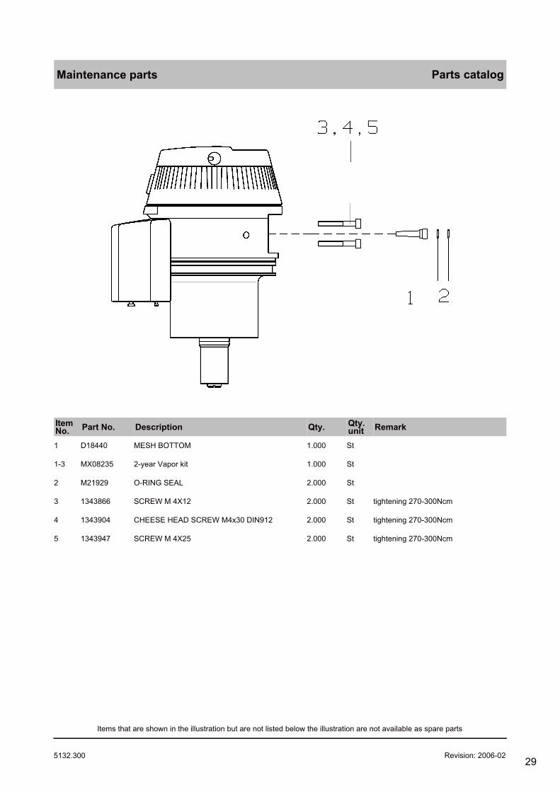
Maintenance parts Parts catalog
ItemNo. Part No. Description Qty. Qty.
unit Remark
1 D18440 MESH BOTTOM 1.000 St
1-3 MX08235 2-year Vapor kit 1.000 St
2 M21929 O-RING SEAL 2.000 St
3 1343866 SCREW M 4X12 2.000 St tightening 270-300Ncm
4 1343904 CHEESE HEAD SCREW M4x30 DIN912 2.000 St tightening 270-300Ncm
5 1343947 SCREW M 4X25 2.000 St tightening 270-300Ncm
Revision: 2006-02-27 12:45:215132.300
Items that are shown in the illustration but are not listed below the illustration are not available as spare parts
29

Plug-in adapter DW-2000 H Parts catalog
ItemNo. Part No. Description Qty. Qty.
unit Remark
1343866 SCREW M 4X12 2.000 St tightening 270 - 300Ncm
1 M34676 HANDLE (PLUG-IN SYSTEM DW) 1.000 St
1-6 M34725 Plug-in adapter DW-2000 H 1.000 St
2 M34677 CAP FOR HANDLE 1.000 St
3 1327542 WASHER A 4,3 DIN 125-A4 1.000 St
5 M34662 BOLT 1.000 St
Revision: 2006-02-27 12:45:215132.300
Items that are shown in the illustration but are not listed below the illustration are not available as spare parts
30

Rep. Set Pflug-In System Parts catalog
ItemNo. Part No. Description Qty. Qty.
unit Remark
1-4 M34907 REP.SET PLUG-IN SYSTEM 1.000 St
Revision: 2006-02-27 12:45:215132.300
Items that are shown in the illustration but are not listed below the illustration are not available as spare parts
31

Plug-in adapter DW 2000 E Parts catalog
ItemNo. Part No. Description Qty. Qty.
unit Remark
1343866 SCREW M 4X12 2.000 St tightening 270 - 300Ncm
1 M34676 HANDLE (PLUG-IN SYSTEM DW) 1.000 St
1-6 M34726 Plug-in adapter DW-2000 E 1.000 St
2 M34677 CAP FOR HANDLE 1.000 St
3 1327542 WASHER A 4,3 DIN 125-A4 1.000 St
5 M34662 BOLT 1.000 St
Revision: 2006-02-27 12:45:215132.300
Items that are shown in the illustration but are not listed below the illustration are not available as spare parts
32

Plug-in adapter DW 2000 I Parts catalog
ItemNo. Part No. Description Qty. Qty.
unit Remark
1343866 SCREW M 4X12 2.000 St tightening 270 - 300 Ncm
1 M34676 HANDLE (PLUG-IN SYSTEM DW) 1.000 St
1-6 M34727 Plug-in adapter DW-2000 I 1.000 St
2 M34677 CAP FOR HANDLE 1.000 St
3 1327542 WASHER A 4,3 DIN 125-A4 1.000 St
5 M34662 BOLT 1.000 St
Revision: 2006-02-27 12:45:215132.300
Items that are shown in the illustration but are not listed below the illustration are not available as spare parts
33

Plug-in adapter DW 2000 S Parts catalog
ItemNo. Part No. Description Qty. Qty.
unit Remark
1343866 SCREW M 4X12 2.000 St tightening 270 - 300Ncm
1 M34676 HANDLE (PLUG-IN SYSTEM DW) 1.000 St
1-6 M34728 Plug-in adapter DW-2000 S 1.000 St
2 M34677 CAP FOR HANDLE 1.000 St
3 1327542 WASHER A 4,3 DIN 125-A4 1.000 St
5 M34662 BOLT 1.000 St
Revision: 2006-02-27 12:45:215132.300
Items that are shown in the illustration but are not listed below the illustration are not available as spare parts
34

Plug-in adapter S-2000 Parts catalog
ItemNo. Part No. Description Qty. Qty.
unit Remark
1343866 SCREW M 4X12 2.000 St tightening 270-300Ncm
1-18 M34821 Plug-in adapter S-2000 1.000 St
2 M34677 CAP FOR HANDLE 1.000 St
4 1327542 WASHER A 4,3 DIN 125-A4 1.000 St
5 M34758 Hand lever 1.000 St
12 M34817 BOLT 1.000 St
Revision: 2006-02-27 12:45:215132.300
Items that are shown in the illustration but are not listed below the illustration are not available as spare parts
35

Vapor plug-in system w. pivot Parts catalog
ItemNo. Part No. Description Qty. Qty.
unit Remark
1 D18400 O-RING SEAL 4.000 St
1-11 M26588 VAPOR PLUG-IN SYSTEM W.PIVOT 1.000 St
2 U04314 O-RING SEAL 2.000 St
5 M05128 PACKING RING 2.000 St
6 1329324 AM4X8 DIN 963-A4/051 2.000 St
10 M28935 FIXING CAM 1.000 St
11 1334514 SCREW AM2X4 DIN 963-A4 2.000 St secured with Loctite 221 andtightening 27-30Ncm
Revision: 2006-02-27 12:45:215132.300
Items that are shown in the illustration but are not listed below the illustration are not available as spare parts
36
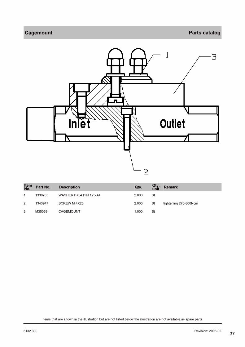
Cagemount Parts catalog
ItemNo. Part No. Description Qty. Qty.
unit Remark
1 1330705 WASHER B 6,4 DIN 125-A4 2.000 St
2 1343947 SCREW M 4X25 2.000 St tightening 270-300Ncm
3 M35059 CAGEMOUNT 1.000 St
Revision: 2006-02-27 12:45:215132.300
Items that are shown in the illustration but are not listed below the illustration are not available as spare parts
37

Keyed filler adapter H Parts catalog
ItemNo. Part No. Description Qty. Qty.
unit Remark
9028953 MA check valve filling adapter 1.000 St
1 M30288 Keyed filler adapter H 1.000 St old version
2 M35320 Keyed Filling Adapter H 1.000 St new version
3 M34614 MODIF.KIT BALL VALVE 1.000 St
4 M35209 MRI Label 1.000 St
Revision: 2006-02-27 12:45:215132.300
Items that are shown in the illustration but are not listed below the illustration are not available as spare parts
38

Keyed filler adapter E Parts catalog
ItemNo. Part No. Description Qty. Qty.
unit Remark
9028953 MA check valve filling adapter 1.000 St
1 M30289 Keyed filler adapter E 1.000 St old version
2 M35321 Keyed Filling Adapter E 1.000 St new version
3 M34614 MODIF.KIT BALL VALVE 1.000 St
4 M35209 MRI Label 1.000 St
Revision: 2006-02-27 12:45:215132.300
Items that are shown in the illustration but are not listed below the illustration are not available as spare parts
39
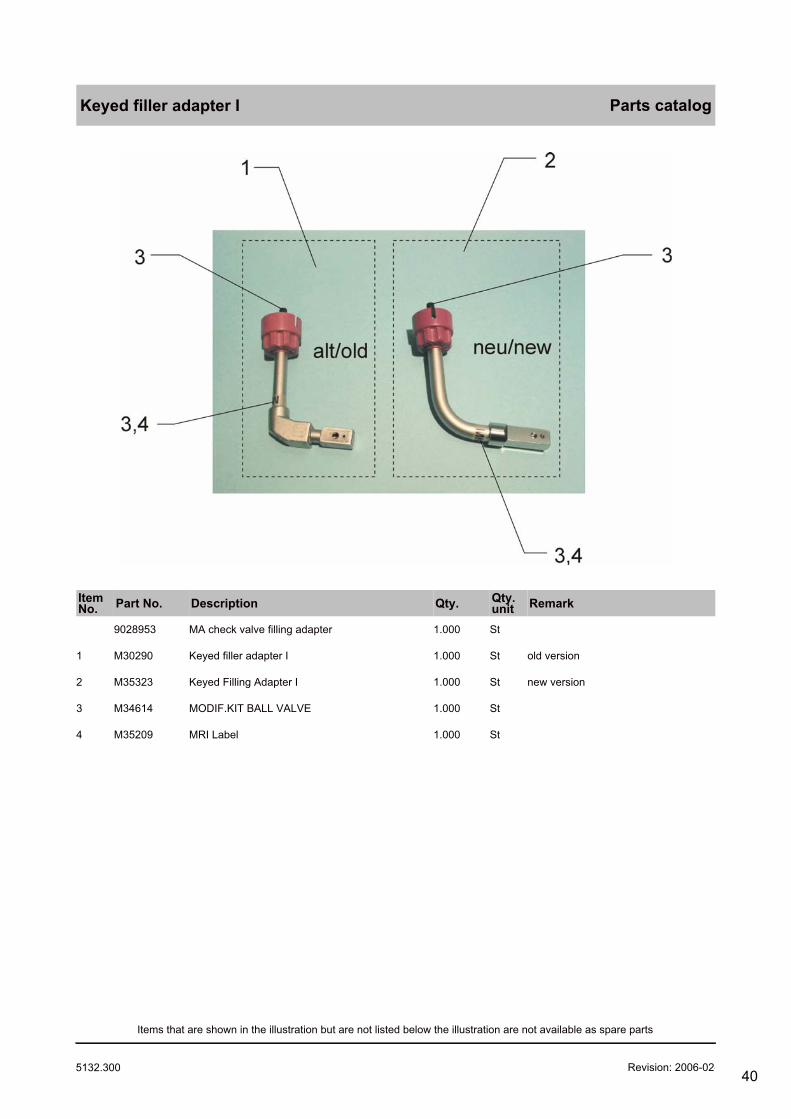
Keyed filler adapter I Parts catalog
ItemNo. Part No. Description Qty. Qty.
unit Remark
9028953 MA check valve filling adapter 1.000 St
1 M30290 Keyed filler adapter I 1.000 St old version
2 M35323 Keyed Filling Adapter I 1.000 St new version
3 M34614 MODIF.KIT BALL VALVE 1.000 St
4 M35209 MRI Label 1.000 St
Revision: 2006-02-27 12:45:215132.300
Items that are shown in the illustration but are not listed below the illustration are not available as spare parts
40

Keyd filler adapter S Parts catalog
ItemNo. Part No. Description Qty. Qty.
unit Remark
9028953 MA check valve filling adapter 1.000 St
1 M31930 Keyed filler adapter S 1.000 St old version
2 M35322 Keyed Filling Adapter S 1.000 St new version
3 M34614 MODIF.KIT BALL VALVE 1.000 St
4 M35209 MRI Label 1.000 St
Revision: 2006-02-27 12:45:215132.300
Items that are shown in the illustration but are not listed below the illustration are not available as spare parts
41

Quik Fil Drain Adapter Parts catalog
ItemNo. Part No. Description Qty. Qty.
unit Remark
M34206 QUIK FIL DRAIN ADAPTER 1.000 St
Revision: 2006-02-27 12:45:215132.300
Items that are shown in the illustration but are not listed below the illustration are not available as spare parts
42

Gas supply block Parts catalog
ItemNo. Part No. Description Qty. Qty.
unit Remark
1 8602767 PRESSURE SENSOR 1.000 St
2 M19241 TOROIDAL SEALING RING 1.000 St
3 AF00220 CUFF 1.000 St
4 D04873 COPPER RING 1.000 St
5 D18348 SCREW PLUG 1.000 St
6 8413666 Pressure regulator 1.000 St
Revision: 2006-02-27 12:45:215132.300
Items that are shown in the illustration but are not listed below the illustration are not available as spare parts
43
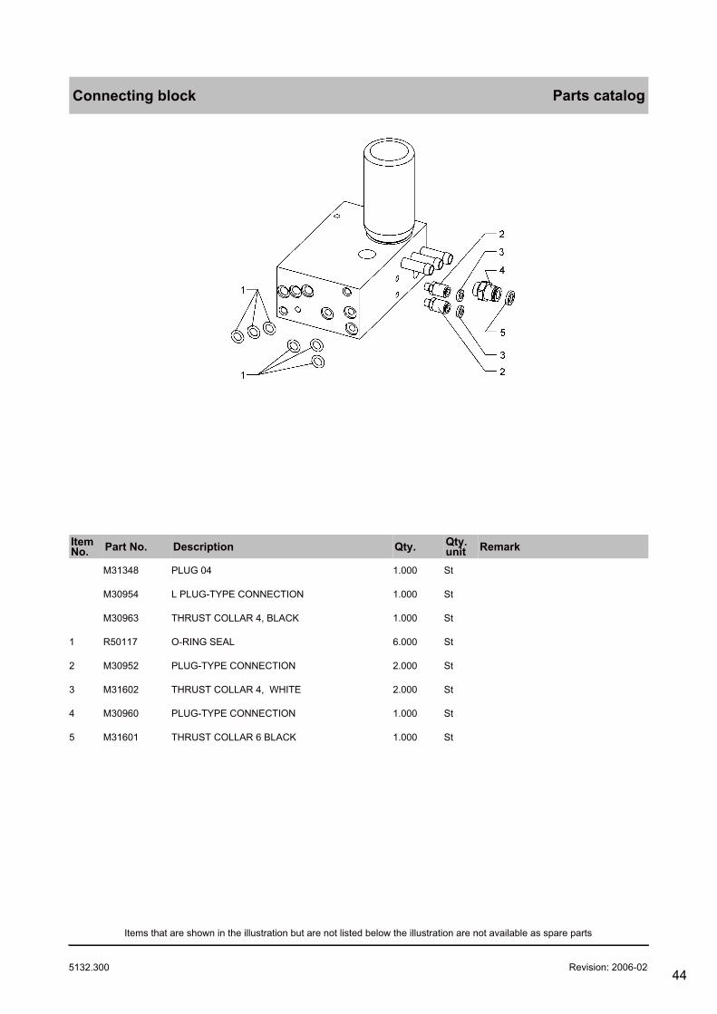
Connecting block Parts catalog
ItemNo. Part No. Description Qty. Qty.
unit Remark
M31348 PLUG 04 1.000 St
M30954 L PLUG-TYPE CONNECTION 1.000 St
M30963 THRUST COLLAR 4, BLACK 1.000 St
1 R50117 O-RING SEAL 6.000 St
2 M30952 PLUG-TYPE CONNECTION 2.000 St
3 M31602 THRUST COLLAR 4, WHITE 2.000 St
4 M30960 PLUG-TYPE CONNECTION 1.000 St
5 M31601 THRUST COLLAR 6 BLACK 1.000 St
Revision: 2006-02-27 12:45:215132.300
Items that are shown in the illustration but are not listed below the illustration are not available as spare parts
44

Absorber and Sleeves Parts catalog
ItemNo. Part No. Description Qty. Qty.
unit Remark
2 M33719 ABSORBER POT 1.000 St
3 M33728 PACKING RING 1.000 St
4 M33720 ABSORBER INSERT, CPL. 1.000 St
Revision: 2006-02-27 12:45:215132.300
Items that are shown in the illustration but are not listed below the illustration are not available as spare parts
45

Monitor control pannel Parts catalog
ItemNo. Part No. Description Qty. Qty.
unit Remark
2 8603235 DISPLAY 1.000 St
Revision: 2006-02-27 12:45:215132.300
Items that are shown in the illustration but are not listed below the illustration are not available as spare parts
46

PGM 2 w. servomex / pato Parts catalog
ItemNo. Part No. Description Qty. Qty.
unit Remark
14 6870567 WATERTRAPS SET OF 12 1.000 St besteht aus 12x 6870530
Revision: 2006-02-27 12:45:215132.300
Items that are shown in the illustration but are not listed below the illustration are not available as spare parts
47

PGM 3 Parts catalog
ItemNo. Part No. Description Qty. Qty.
unit Remark
13 6870567 WATERTRAPS SET OF 12 1.000 St 12 x 6870511
Revision: 2006-02-27 12:45:215132.300
Items that are shown in the illustration but are not listed below the illustration are not available as spare parts
48

Primus
Assembly Description Part No.
Parts catalog
Absorber and Sleeves
ABSORBER INSERT, CPL. M33720
ABSORBER POT M33719
PACKING RING M33728
Accessories
GA Endotracheale Bronchusabsau 9037477
GA WaterLock me 9029423
Accessories Anaesthesia
ANAEST.-SET KUHN TYPE K M34823
ANAEST.-SET KUHNTYPE E M34822
ANAESTHETIC-MASK SZ,3 2165759
ANAESTHETIC-MASK SZ.1 2165732
ANAESTHETIC-MASK SZ.2 2165740
Connection nozzle O2 6mm M06258
O2 flowmeter 16L, rail, Nist 2M86248
O2 flowmeter 16L,rail,90g,Nist 2M86249
Accessories Jar Set
FILTER MK00514
Accessories Julian
BREATH.HOSE 150CMLONG SLEEVE 2166046
BREATH.HOSE LONG 110CM SLEEVE 2166038
NOZZLE 22/22 M25647
Sample Line Set (10pcs) 8290286
SILICON-BREATHING BAG 2,3 L 2166062
Y-PIECE ADULT,LUER LOCK M33278
Accessories Pedeatrics
90 -LUERLOCK FOR NEONATES M34568
Breathing bag 0,5L ISO 2165686
BREATHING HOSE K 22/10 1,5M 2165961
BREATHING HOSE K 22/22 1,1M 2165678
CONNECTION PIECE 2M12754
CORRUGATED BELLOWS K 8410079
HOSE 4X1,5-SI 50 SH A NF 1190520
HOSESET CIRCLESYSTEM CHILDREN M27542
NOZZLE 22/22 M25647
PEDIATRIC ACCESSORY M33681
SET CAPS 8402953
Y-PIECE 90DEGREE 8403075
5132.300 Revision: 2006-02
49

Primus
Assembly Description Part No.
Parts catalog
Accessories Suction
ACCESS.SUCTION UNIT F.JULIAN 8601179
ANGULAR PORCELAIN BUSH 2M19063
ANGULAR PORCELAIN BUSH M30159
ASPIRATION HOSE M25780
CYLINDER CAP WITH VALVE 2M85012
HOSE 5X2SI 60SHA NF M25779 1203606
RECEPTACLE 2M85594
SECRETION CONTROL GLASS M07582
AGS system
FILTER M33294
AGS system Canada
FILTER M33294
AGS-System
AGS CONTAINER M33292
AGS-SYSTEM, BASIC UNIT M33300
FILTER M33294
Label Vacuum Suction 8605459
AIR
AIR CONNECTING HOSE 3M (BLACK) M29241
AIR CONNETING HOSE 1,5M(BLACK) M29281
AIR-CONNECTING HOSE 1,5M M29279
AIR-CONNECTING HOSE 5M M29259
AIR-CONNECTING HOSE 5M (BLACK) M29261
AIR-HOSE NIST 1,5M DIN PROBE M34407
AIR-HOSE NIST 3M DIN PROBE M34408
AIR-HOSE NIST 5M DIN PROBE M34409
AIR-ZV-HOSE 1,5M NIST EN-COLOR 8602519
AIR-ZV-HOSE 3M NIST EN-COLOR 8602520
AIR-ZV-HOSE 5M NIST EN-COLOR 8602521
5132.300 Revision: 2006-02
50

Primus
Assembly Description Part No.
Parts catalog
AIR/O2
02/AIR-CONNECTING HOSE 3M M29243
AIR/O2-ZV-HOSE 1,5M NIST EN-C. 8602525
AIR/O2-ZV-HOSE 3M NIST EN-COL. 8602526
AIR/O2-ZV-HOSE 5M NIST EN-COL. 8602527
O2/AIR-HOSE NIST 1,5MDIN PROBE M34410
O2/AIR-HOSE NIST 3M DIN PROBE M34411
O2/AIR-HOSE NIST 5M DIN PROBE M34412
O2-AIR CONNECT.HOSE 3M(BLACK) M29245
O2-AIR CONNECT.HOSE 5M (BLACK) M29265
O2-AIR CONNECTING HOSE 1,5M M29283
O2-AIR CONNECTING HOSE 5M M29263
O2-AIR-CONNECT.HOSE 1,5(BLACK) M29285
Anaesthesia Acc. Kuhn
ANAEST.-SET KUHN TYPE K M34823
ANAESTHETIC-GAS SCAV.(KUHN) M25838
COUPLING SLEEVE M13506
Basic Unit
AGS-SYSTEM, BASIC UNIT M33300
Cagemount
CAGEMOUNT M35059
SCREW M 4X25 1343947
WASHER B 6,4 DIN 125-A4 1330705
Central Air distributor
AIR-DISTRIBUTOR 1,5M M28963
AIR-DISTRIBUTOR 1,5M (BLACK) M29866
AIR-DISTRIBUTOR 1,5M DIN PROBE M34561
AIR-DISTRIBUTOR 3M M30709
AIR-DISTRIBUTOR 3M (BLACK) M30711
AIR-DISTRIBUTOR 3M DIN-PROBE M34562
AIR-DISTRIBUTOR 5M M30710
AIR-DISTRIBUTOR 5M (BLACK) M30712
AIR-DISTRIBUTOR 5M DIN-PROBE M34563
AIR-ZV-DISTRIB.1,5M NIST EN-C. 8602531
AIR-ZV-DISTRIB.3M NIST EN-COL. 8602532
AIR-ZV-DISTRIB.5M NIST EN-COL. 8602533
5132.300 Revision: 2006-02
51

Primus
Assembly Description Part No.
Parts catalog
Central O2 distributor
DIAPHRAGM SEPARATION M34492
O2-DISTR.1,5M DIN-ST.NIST-FN M34941
O2-HOSE NIST 5M DIN PROBE M34403
O2-ZV-DISTRIB.1,5M DIN BLUE 8602534
O2-ZV-DISTRIB.1,5M NIST EN-C. 8602528
O2-ZV-DISTRIB.3M DIN BLUE 8602535
O2-ZV-DISTRIB.3M NIST EN-COLOR 8602529
O2-ZV-DISTRIB.5M DIN BLUE 8602536
O2-ZV-DISTRIB.5M NIST EN-COLOR 8602530
Clutch adapter
Adapter AIR DIN/DIN-coupling M28031
Adapter AIR NIST/DIN-coupling M35058
Adapter N2O DIN/DIN-coupling M23875
Adapter N2O NIST/DIN-coupling M35057
Adapter O2 NIST/DIN-coupling M35056
O2-COUPLING HOSE 0,15M M23874
Connecting block
L PLUG-TYPE CONNECTION M30954
O-RING SEAL R50117
PLUG 04 M31348
PLUG-TYPE CONNECTION M30960
PLUG-TYPE CONNECTION M30952
THRUST COLLAR 4, WHITE M31602
THRUST COLLAR 4, BLACK M30963
THRUST COLLAR 6 BLACK M31601
Connectors and Hoses
AIR-NIST-CONNECTION MX08054
CONNECTING HOSE 1,2M AIR/DISS MX08058
HOSEINE NIST,O2 0,5M MX08055
HOSELINE NIST/AIR 0,5M MX08057
HOSELINE NIST-NIST N2O, O,5M MX08056
N2O-NIST-CONNECTION MX08053
OXYGENE-NIST-CONNECTION MX08052
Draeger Sorb
Draegersorb FREE (5L) MX50050
Ejector type aspirat. NIST Air
FILTER MK00514
Suction Ejector, NIST MK01420
5132.300 Revision: 2006-02
52

Primus
Assembly Description Part No.
Parts catalog
Ejector type aspirator
BACTERIA FILTERS CH00102
SET OF 5 BACTERIA FILT.(CH102) 6723976
Filling Adapters
Keyed filler adapter E M30289
Keyed filler adapter H M30288
Keyed filler adapter I M30290
Keyed filler adapter S M31930
QUIK FIL DRAIN ADAPTER M34206
Filters
BACTERIA FILTER 8402868
BACTERIA FILTERS CH00102
FILTER MK00514
SET MIC.FILTER 654ST-ISOCLICK 6733895
SET OF 5 BACTERIA FILT.(CH102) 6723976
Gas supply block
COPPER RING D04873
CUFF AF00220
Pressure regulator 8413666
PRESSURE SENSOR 8602767
SCREW PLUG D18348
TOROIDAL SEALING RING M19241
High Pressure Sensors
HIGH PRESSURE SENSOR AIR 8603520
HIGH PRESSURE SENSOR N2O 8603315
HIGH PRESSURE SENSOR O2 8603316
Holders Vaporizer
HOLDING DEVICE PARK.POS.RAIL M26966
SUPPORT FOR PARKING POSITION M25102
Hose DIN, device NIST
ADAPTER O2 (DIN/NIST) M32366
ADAPTOR AIR (DIN/NIST) M32368
ADAPTOR AIR/O2 (DIN/NIST) M32370
ADAPTOR N2O (DIN/NIST) M32367
ADAPTOR VAC (DIN/NIST) M32369
Hose DISS, device NIST
ADAPTOR-AIR,DISS-NIST M34877
ADAPTOR-N2O,DISS-NIST M34876
ADAPTOR-O2,DISS-NIST M34875
ADAPTOR-VAC,DISS-NIST M34878
5132.300 Revision: 2006-02
53

Primus
Assembly Description Part No.
Parts catalog
Hose NIST, device DIN
ADAPTOR AIR (NIST/DIN) M32495
ADAPTOR AIR/O2 (NIST/DIN) M32497
ADAPTOR N2O (NIST/DIN) M32494
ADAPTOR O2 (NIST/DIN) M32493
ADAPTOR VAC (NIST/DIN) M32496
Instructions for Use
AGS A-Gas Awayline hu/cz 9038239
AGS A-Gas Awayline ru/pl 9038207
AGS A-Gas Awayline sv/no 9038206
AGS A-Gas Awayline zh/jp 9038208
INSTRUCTIONS FOR USE AGS DA/IT 9029425
Instructions for Use AGS de/en 9029327
INSTRUCTIONS FOR USE AGS FR/ES 9029426
INSTRUCTIONS FOR USE AGS FR/NL 9037424
Keyd filler adapter S
Keyed filler adapter S M31930
Keyed Filling Adapter S M35322
MA check valve filling adapter 9028953
MODIF.KIT BALL VALVE M34614
MRI Label M35209
Keyed filler adapter E
Keyed filler adapter E M30289
Keyed Filling Adapter E M35321
MA check valve filling adapter 9028953
MODIF.KIT BALL VALVE M34614
MRI Label M35209
Keyed filler adapter H
Keyed filler adapter H M30288
Keyed Filling Adapter H M35320
MA check valve filling adapter 9028953
MODIF.KIT BALL VALVE M34614
MRI Label M35209
Keyed filler adapter I
Keyed filler adapter I M30290
Keyed Filling Adapter I M35323
MA check valve filling adapter 9028953
MODIF.KIT BALL VALVE M34614
MRI Label M35209
5132.300 Revision: 2006-02
54

Primus
Assembly Description Part No.
Parts catalog
KIT AGS Adapter
MODIF.AGS-ADAPTER TITUS/SA2 M32976
Kit Parking holder
SUPPORT FOR PARKING POSITION M25102
Maintanance Parts/Service Sets
FILTER M33294
Maintenance parts
2-year Vapor kit MX08235
CHEESE HEAD SCREW M4x30 DIN912 1343904
MESH BOTTOM D18440
O-RING SEAL M21929
SCREW M 4X12 1343866
SCREW M 4X25 1343947
Manual Ventilation
Baby-Resutator 2000 2120941
Resutator 2000 adults 2120046
SILICON-BREATHING BAG 2,3 L 2166062
5132.300 Revision: 2006-02
55

Primus
Assembly Description Part No.
Parts catalog
Manuals\Techn. Documentation
GA VAPOR 2000 cs DB01358
GA VAPOR 2000 da DB01359
GA VAPOR 2000 DE DB01188
GA VAPOR 2000 EN DB01189
GA VAPOR 2000 ES DB01191
GA VAPOR 2000 FR DB01190
GA VAPOR 2000 hu DB01356
GA VAPOR 2000 IT DB01260
GA VAPOR 2000 ja DB01353
GA VAPOR 2000 NL DB01261
GA VAPOR 2000 no DB01355
GA Vapor 2000 pl DB01357
GA VAPOR 2000 pt DB01352
GA VAPOR 2000 ru DB01351
GA Vapor 2000 sk DB01362
GA VAPOR 2000 SV DB01262
GA Vapor 2000 tr DB01363
GA VAPOR 2000 zh DB01354
GA-VAPOR 2000 - FI DB01263
IFU VAPOR 2000 en US DB01273
TD Vapor 2000 de 9036025
TD Vapor 2000 en 9036026
TD Vapor 2000 es 9036197
TD Vapor 2000 fr 9036027
Medibus
GA Dräger RS 232 Medibus de 9028320
GA MEDIBUS f. Primus en 9037426
Manual Dräger RS232 Medibus EN 9028258
Monitor control pannel
DISPLAY 8603235
5132.300 Revision: 2006-02
56

Primus
Assembly Description Part No.
Parts catalog
N2O
N2O-CONNECT.HOSE 1,5M (BACK) M29277
N2O-CONNECT.HOSE 3M (BLACK) M29237
N2O-CONNECT.HOSE 5M (BLACK) M29257
N2O-CONNECTING HOSE 1,5M M29275
N2O-CONNECTING HOSE 5M M29255
N2O-CONNECTION HOSE 3M M29235
N2O-HOSE NIST 1,5M DIN PROBE M34404
N2O-HOSE NIST 3M DIN PROBE M34405
N2O-HOSE NIST 5M DIN PROBE M34406
N2O-ZV-HOSE 1,5M NIST EN-COLOR 8602516
N2O-ZV-HOSE 3M NIST EN-COLOR 8602517
N2O-ZV-HOSE 5M NIST EN-COLOR 8602518
O2
O2-CONNECT.HOSE 1,5M (BLACK) M29273
O2-CONNECT.HOSE 3M (BLACK) M29233
O2-CONNECT.HOSE 5M (BLACK) M29253
O2-CONNECTING HOSE 1,5M M29271
O2-CONNECTING HOSE 5M M29251
O2-CONNECTION HOSE 3M M29231
O2-HOSE NIST 1,5M DIN-PROBE M34401
O2-HOSE NIST 3M DIN PROBE M34402
O2-HOSE NIST 5M DIN PROBE M34403
O2-ZV-HOSE 1,5M NIST EN-COLOR 8602513
O2-ZV-HOSE 5M NIST EN-COLOR 8602515
O2-ZV-HOSE3M NIST EN-COLOR 8602514
5132.300 Revision: 2006-02
57

Primus
Assembly Description Part No.
Parts catalog
O2-Pressure reducer G3/4
CONNECTION PIECE 2312602
CONNECTION PIECE 2312603
DIAPHRAGM VALVE W.O-RING SEAL 2312600
FLAT PACKING 2312593
HIGH PRESSURE SENSOR N2O 8603709
HIGH PRESSURE SENSOR N2O AF00532
HIGH PRESSURE SENSOR O2 8603704
HIGH PRESSURE SENSOR O2 AF00528
LOCK G 3/8" 2312604
LOCK M10X1 2312605
N2O-PRESSURE REDUCER G3/4I M34017
N2O-PRESSURE REDUCER G3/8 M34018
N2O-PRESSURE REDUCER GH M34020
N2O-PRESSURE REDUCER GI M34022
N2O-PRESSURE REDUCER GX M34021
N2O-PRESSURE REDUCER PIN INDEX M34019
NUT N2O GER. G 3/4" 2312585
NUT N2O GER. G 3/8" 2312586
NYLON-GASKET 3/8" 2312606
NYLON-GASKET F. THREAD M10X1 2312607
O2-PRESSURE REDUCER G3/4 M34007
O2-PRESSURE REDUCER GA M34009
O2-PRESSURE REDUCER GB-HS M34012
O2-PRESSURE REDUCER GC-HT M34016
O2-PRESSURE REDUCER GE M34013
O2-PRESSURE REDUCER GO M34014
O2-PRESSURE REDUCER PIN INDEX M34008
O-RING SEAL N2O GERMANY 2312576
O-RING SEAL N2O GERMANY 3/8" 2312577
O-RING SEAL N2O GH 2312578
O-RING SEAL N2O GJ 2312579
O-RING SEAL O2 GA 2312573
O-RING SEAL O2 GC+GB 2312571
O-RING SEAL O2 GE 2312574
O-RING SEAL O2 GERMANY 2312572
O-RING SEAL O2 GO 2312575
PIN-INDEX BOW N2O 2312591
PIN-INDEX BOW O2 2312590
PIN-INDEX CONNECTING BRANCH 2312592
PRESS.RED.+SENSOR N2O PIN IND. AF00530
PRESS.RED.+SENSOR O2 PIN INDEX AF00529
PRESSURE GAUGE N2O 2312596
PRESSURE GAUGE O2 2312595
PRESSURE GAUGE PACKING RING 2312597
5132.300 Revision: 2006-02
58
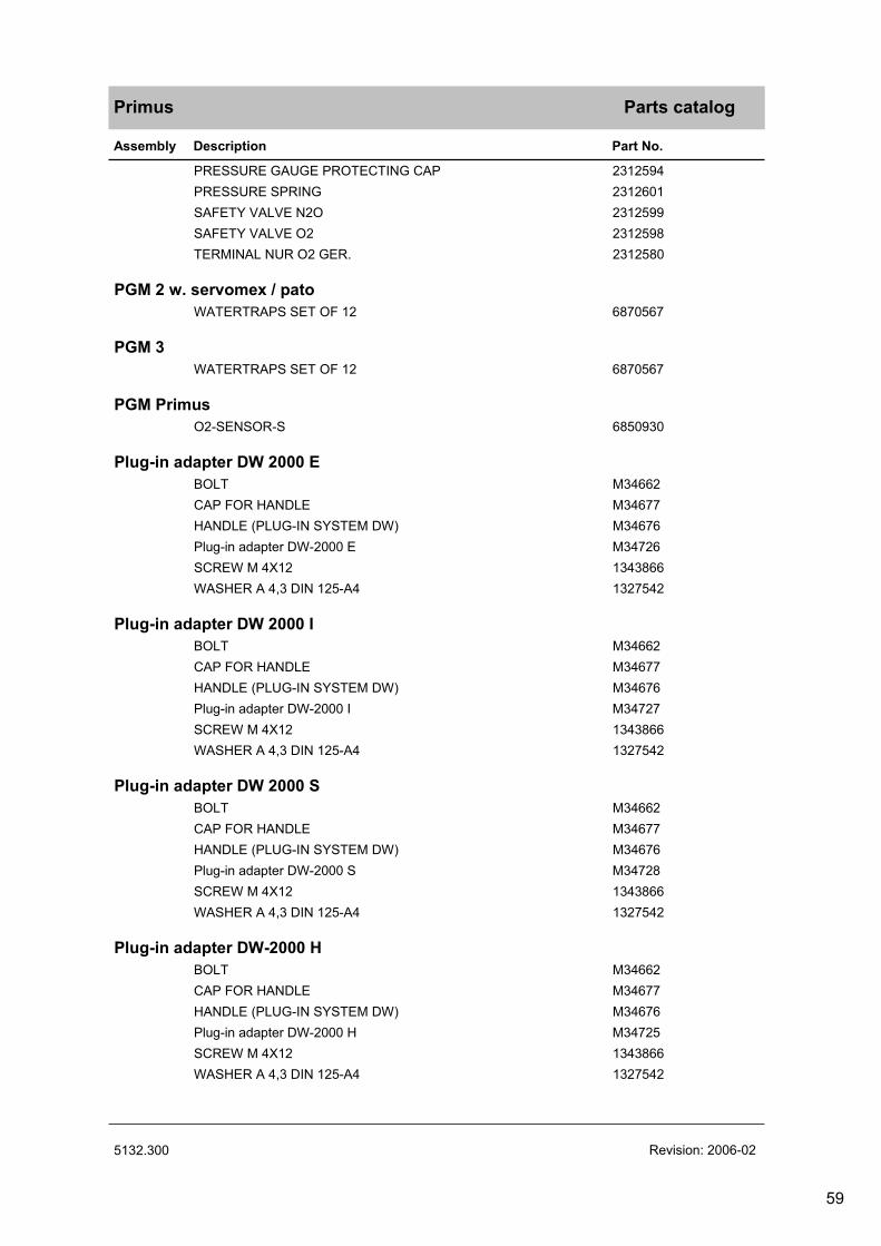
Primus
Assembly Description Part No.
Parts catalog
PRESSURE GAUGE PROTECTING CAP 2312594
PRESSURE SPRING 2312601
SAFETY VALVE N2O 2312599
SAFETY VALVE O2 2312598
TERMINAL NUR O2 GER. 2312580
PGM 2 w. servomex / pato
WATERTRAPS SET OF 12 6870567
PGM 3
WATERTRAPS SET OF 12 6870567
PGM Primus
O2-SENSOR-S 6850930
Plug-in adapter DW 2000 E
BOLT M34662
CAP FOR HANDLE M34677
HANDLE (PLUG-IN SYSTEM DW) M34676
Plug-in adapter DW-2000 E M34726
SCREW M 4X12 1343866
WASHER A 4,3 DIN 125-A4 1327542
Plug-in adapter DW 2000 I
BOLT M34662
CAP FOR HANDLE M34677
HANDLE (PLUG-IN SYSTEM DW) M34676
Plug-in adapter DW-2000 I M34727
SCREW M 4X12 1343866
WASHER A 4,3 DIN 125-A4 1327542
Plug-in adapter DW 2000 S
BOLT M34662
CAP FOR HANDLE M34677
HANDLE (PLUG-IN SYSTEM DW) M34676
Plug-in adapter DW-2000 S M34728
SCREW M 4X12 1343866
WASHER A 4,3 DIN 125-A4 1327542
Plug-in adapter DW-2000 H
BOLT M34662
CAP FOR HANDLE M34677
HANDLE (PLUG-IN SYSTEM DW) M34676
Plug-in adapter DW-2000 H M34725
SCREW M 4X12 1343866
WASHER A 4,3 DIN 125-A4 1327542
5132.300 Revision: 2006-02
59

Primus
Assembly Description Part No.
Parts catalog
Plug-in adapter S-2000
BOLT M34817
CAP FOR HANDLE M34677
Hand lever M34758
Plug-in adapter S-2000 M34821
SCREW M 4X12 1343866
WASHER A 4,3 DIN 125-A4 1327542
Plugs
AGSS ANGLE PROBE / TYPE 1 / EN G60495
AGSS PROBE/STRAIGHT-TYPE1/ EN G60580
ANAESTH.WASTE GAS PROBE 45 G60440
Pressure Gauges
PRESSURE GAUGE AIR MX08049
PRESSURE GAUGE N2O,CO2,XE MX08050
PRESSURE GAUGE O2 MX08048
Pressure Reducer
Press.Red.Air,DIN477-1,Primus 8603719
Press.Red.Air,PIN IND.Primus 8603718
Press.Red.Air.NF E29-650,Prim 8603720
Press.Red.N2o,DIN477-1/11,Prim 8603463
Press.Red.N2o,DIN477-1/12,Prim 8603464
Press.Red.N2o,NF E29-650,Prim 8603711
Press.Red.N2o,PIN IND.Primus 8603462
Press.Red.o2, DIN477-1,Primus 8603465
Press.Red.o2,DIN477-1/6,Primus 8603706
Press.Red.o2,NF E29-650,Primus 8603707
Press.Red.o2,PIN INDEX,Primus 8603466
Primus 1 annual
DIAPHRAGM,CUP 2600650
FILTER MAT 6870910
FILTER MAT 8603662
FILTER MAT 8603301
FILTER MAT 8603144
O-RING SEAL U04314
5132.300 Revision: 2006-02
60

Primus
Assembly Description Part No.
Parts catalog
Primus 2 annual
DIAPHRAGM 8603780
DIAPHRAGM M33275
DIAPHRAGM,CUP 2600650
FILTER MAT 6870910
FILTER MAT 8603301
FILTER MAT 8603585
FILTER MAT 8603662
FILTER MAT 8603144
MESH BOTTOM M19238
NAFION HOSE 150 LG. 8601238
O-RING SEAL R52382
O-RING SEAL U04314
SEALING WASHER 8603781
Primus 3 annual
Battery 8603057
DIAPHRAGM,CUP 2600650
FILTER MAT 8603662
FILTER MAT 8603144
FILTER MAT 8603301
FILTER MAT 6870910
O-RING SEAL U04314
Products concerned
Vapor 2000 Enflurane M35150
Vapor 2000 Halothane M35140
Vapor 2000 Isoflurane M35160
Vapor 2000 Sevoflurane M35170
Quik Fil Drain Adapter
QUIK FIL DRAIN ADAPTER M34206
Rep. Set Pflug-In System
REP.SET PLUG-IN SYSTEM M34907
RS AGS- Schienenklaue
Lever-type clamp M25739
MODIFICATION AGS-RAIL CLAMP M32967
RS SpO2
Upgrade kit Spo2 Primus 8603870
Secretion bottles with claw
Lever-type clamp M25739
RECEPTACLE 2M85594
5132.300 Revision: 2006-02
61

Primus
Assembly Description Part No.
Parts catalog
Sensors and Gas Measurement
O2-SENSOR-S 6850930
Sample Line Set (10pcs) 8290286
Set of 5 Spirolog sensors 8403735
SpiroLife MK01900
WATERTRAPS SET OF 12 6870567
Sets and Spare Parts
MESH BOTTOM D02316
PROTECTING CAP MX08051
REP.SET GASKET MX08061
REP.SET GASKET/B (ENGLAND ) MX08159
REP.SET GASKET/C (USA) MX08158
REP.SET GASKET/F ( FRANKREICH) MX08157
REP.SET GASKET/N (NIEDERLANDE) MX08160
SET OF PACKING RINGS D20215
Software 1.n
EB zur GA Primus de/en 9037930
GA Primus SW 1.06 fr 9037731
GA Primus SW 1.06 no 9037738
GA Primus SW 1.06 da 9037668
GA Primus SW 1.06 en 9037730
GA Primus SW 1.06 es 9037732
GA Primus SW 1.06 fi 9037737
GA Primus SW 1.06 ge 9037729
GA Primus SW 1.06 hu 9037742
GA Primus SW 1.06 it 9037733
GA Primus SW 1.06 nl 9037734
GA Primus SW 1.06 pl 9037740
GA Primus SW 1.06 pt 9037741
GA Primus SW 1.06 ru 9037736
GA Primus SW 1.06 sk 9037748
GA Primus SW 1.06 sv 9037735
GA Primus SW 1.06 zh 9037739
5132.300 Revision: 2006-02
62

Primus
Assembly Description Part No.
Parts catalog
Software 2.n
50 Primus SW 2.n fr 9037992
GA Primus SW 2.n cs 9038006
GA Primus SW 2.n da 9038000
GA Primus SW 2.n de 9037990
GA Primus SW 2.n el 9038008
GA Primus SW 2.n en 9037991
GA Primus SW 2.n es 9037993
GA Primus SW 2.n fi 9037998
GA Primus SW 2.n hu 9038003
GA Primus SW 2.n it 9037994
GA Primus SW 2.n nl 9037995
GA Primus SW 2.n no 9037999
GA Primus SW 2.n pl 9038005
GA Primus SW 2.n pt 9038001
GA Primus SW 2.n ru 9037997
GA Primus SW 2.n sk 9038004
GA Primus SW 2.n sv 9037996
GA Primus SW 2.n zh 9038002
Suction hoses
AGS-SCAVANGER HOSE 0,5M M35015
AGS-SCAVANGER HOSE 1,5M M33297
AGS-SCAVANGER HOSE 3M M33298
AGS-SCAVANGER HOSE 5M M33299
TD Primus
TD Primus de 9036003
TD Primus de 9036180
TD Primus en 9036004
TD Primus es 9036005
TD Primus fr 9036006
TDPrimus es 9036179
5132.300 Revision: 2006-02
63

Primus
Assembly Description Part No.
Parts catalog
VAC
VAC.-CONNECT.HOSE 1,5M(BLACK) M29289
VAC.-CONNECT.HOSE 3M (BLACK) M29249
VAC.-CONNECT.HOSE 5M (BLACK) M29269
VAC-HOSE NIST 1,5M DIN PROBE M34413
VAC-HOSE NIST 3M DIN PROBE M34414
VAC-HOSE NIST 5M DIN PROBE M34415
VACUUM-CONNECTION HOSE 1,5M M29287
VACUUM-CONNECTION HOSE 3M M29247
VACUUM-CONNECTION HOSE 5M M29267
VAC-ZV-HOSE 1,5M NIST EN-COLOR 8602522
VAC-ZV-HOSE 3M NIST EN-COLOR 8602523
VAC-ZV-HOSE 5M NIST EN-COLOR 8602524
Valve
CAP 1,BLACK M24597
Vapor plug-in system w. pivot
AM4X8 DIN 963-A4/051 1329324
FIXING CAM M28935
O-RING SEAL U04314
O-RING SEAL D18400
PACKING RING M05128
SCREW AM2X4 DIN 963-A4 1334514
VAPOR PLUG-IN SYSTEM W.PIVOT M26588
Vaporizer 19.n
DEVAPOR GERMAN M32600
E-VAPOR 19.3/5% PIN SAFETY DB01128
H.VAPOR 19.3/4% PIN SAFETY DB01154
I-VAPOR 19.3/5% PIN SAFETY DB01129
S-VAPOR 19.3/8% ABBOTT DB01180
S-VAPOR 19.3/8% PIN SAFETY DB01166
Without plug, color EN 739
AIR-DISTRIBUTOR 5M,NO PLUG M34564
CS-HOSE N2O,5M,NO PLUG M34417
CS-HOSE AIR 5M, NO PROBE M34418
CS-HOSE AIR-O2,5M,NO PLUG M34420
CS-HOSE O2 5M, NO PROBE M34416
CS-HOSE VAC,5M,NO PLUG M34419
O2-DISTRIBUTOR 5M,NO PLUG M34565
5132.300 Revision: 2006-02
64

Primus
Assembly Description Part No.
Parts catalog
Without plug, no color
AIR-DISTRIB.NIST 5M,BL,N.PROBE M32677
AIR-HOSE 5M NIST BL., NO PROBE M32039
N2O-HOSE 5M,NIST,BL.,NO PROBE M32038
O2/AIR HOSE 5M NIST,BL.,NO PR. M32047
O2-DISTRIB.NIST 5M,BL,N.PROBE M32679
O2-HOSE 5M NIST BL., NO PROBE M32037
VAC.HOSE 5M,NIST,BL.,NO PROBE M32046
Y-Pieces
Y-PIECE 8405435
Y-PIECE 90DEGREE 8403075
Y-PIECE ADULT M25682
Y-PIECE ADULT,LUER LOCK M33278
Y-PIECE ADULT,STRAIGHT M25650
Y-PIECE F.TEMPERATURE SENSING M30543
Y-PIECE F+P 8412220
Y-PIECE STRAIGHT PAED M27077
5132.300 Revision: 2006-02
65

66

Test List (TL)
Primus
This test list can be processed with standard commercially available test aids and tools, but does not replace the inspections and maintenance work carried out by the manufacturer.
Tests marked with the "check" symbol are listed in the Test List Report and can be documented there.
Country-specific ventilation mode terms in SW versions earlier than 2.0:
International: Man./Spont = France: Man./Spont.International: IPPV mode = France: VCInternational: PCV mode = France: VPC
Country-specific ventilation mode terms in SW versions 2.0 or later:
International: Man./Spont. = France: Man./Spont.International: Vol.Mode = France: Mode Vol.International: Press.Mode = France: Mode Press.International: Press.Supp. = France: A.I. = (option)
Conversion table: 1 bar = 14.504 PSI / 1 mbar = 1.01973 cm H2O
Primus 1/262003-12 Released

Schutzvermerk DIN 34 beachten. Copyright reserved.
Device configuration1
Serial numbers1.1
Primus1.1.1
The serial number is located on the rear of the Primus.
[__________txt]
Breathing system cover1.1.2
The serial number is located on the rim of the cover.
[__________txt]
Breathing system valve plate1.1.3
The serial number is located on the heating surface.
[__________txt]
Respiratory gas block1.1.4
The serial number is located under the cover of the piston cylinder unit.
[__________txt]
Serial numbers (options)1.2
External bronchial suction device1.2.1
(If a number is present.)
[__________txt]
High-pressure regulator O21.2.2 [__________txt]
High-pressure regulator N2O1.2.3 [__________txt]
High-pressure regulator AIR1.2.4 [__________txt]
High-pressure cylinder O21.2.5
(If a number is present.)
[__________txt]
High-pressure cylinder N2O1.2.6
(If a number is present.)
[__________txt]
High-pressure cylinder AIR1.2.7
(If a number is present.)
[__________txt]
Software versions1.3
Primus is in "Standb"y mode.
Press the "Standard Config" softkey and, if necessary, enter the security code.Press the "System Information" softkey.Read out the following software versions.
Mobi1.3.1 [__________txt]
Primus 2/262003-12 Released

Schutzvermerk DIN 34 beachten. Copyright reserved.
MIXER MA1.3.2 [__________txt]
MIXER SV1.3.3 [__________txt]
VGC MA1.3.4 [__________txt]
VGC SV1.3.5 [__________txt]
PGM1.3.6
The software version of the "PGM" is displayed for approximately 2 minutes after power-up.
[__________txt]
Power pack1.3.7 [__________txt]
Primus 3/262003-12 Released

Schutzvermerk DIN 34 beachten. Copyright reserved.
Electrical safety2
For a detailed description of the electrical safety tests, see DORIS under "Electrical tests/Test documents/Electrical safety tests" or eSIS under "General/Electrical tests/Electrical safety tests".
General2.1
The following steps describe the electrical safety tests according to IEC 60601 (or UL 2601-1) and VDE 0751. Any decision about performing safety checks according to VDE 0751 or IEC 60601 must be made under consideration of applicable national regulations.
The Primus conforms to the requirements of protection class I. With option SpO2 to type BF.
Visual check2.2
Precondition:Primus is switched off.Power plug is unplugged.
Check the following components are in perfect working condition:Mains power cable including strain relief.
Auxiliary sockets.
On auxiliary sockets with automatic circuit-breakers, check the circuit-breakers are switched on.The automatic circuit-breakers are switched on.
On auxiliary sockets with automatic circuit-breakers, check the ratings correspond to the imprint.The ratings correspond to the imprint.[OK]
[__________OK]
Electrical safety according to VDE 07512.3
INFO:When testing to IEC60-601 or UL2601-1, continue with test item 2.4.
Precondition:Primus is switched off.Power plug is unplugged.
Protective earth conductor test2.3.1
Test sequence2.3.1.1
Connect the test probe to the following test points one after the other:Power pack earthing studPE contacts on auxiliary sockets
The protective earth conductor resistance at any test point must be less than/equal to 0.3 ohms.
PE conductor test value2.3.1.2
Test value including power cable:R = less than/equal to 0.3 ohms.
[__________OK]
Primus 4/262003-12 Released

Schutzvermerk DIN 34 beachten. Copyright reserved.
Equivalent device leakage current test2.3.2
Initial equivalent device leakage current2.3.2.1
Ileak less than or equal to 1000 μA
Each initial measured value should be included in a new report.
The repeat measurements may exceed the initial value by max. 50%, but, at the same time, must be less than/equal to 750μA.
[__________μA]
Repeat measurement of equivalent device leakage current2.3.2.2
Ileak less than/equal to 1000 μA, but maximum permissible deviation from initial value is 50%.
[__________μA]
Equivalent patient leakage current test2.3.3
INFO:This test is only required if the SpO2 option is fitted.
Initial equivalent patient leakage current2.3.3.1
Ileak less than/equal to 50 μA.
Each initial measured value should be included in a new report.
The repeat measurements may exceed the first measured value by max. 50%. In the case of initial measured values < 20 μA, repeat measurements may deviate by up to 10 μA.
[__________μA]
Repeat measurement of equivalent patient leakage current2.3.3.2
Ileak less than/equal to 50 μA.
[__________μA]
Electrical safety to IEC 60-6012.4
INFO:The test to UL2601-1 is satisfied by testing to IEC 60-601-1. Differing limit values are marked.
Precondition:Primus is switched off.Power plug is unplugged.
Protective earth conductor test2.4.1
Test sequence2.4.1.1
Connect the test probe to the following test points one after the other:Power pack earthing stud.PE contacts on auxiliary sockets.
The protective earth conductor resistance at any test point must be less than/equal to 0.3 ohms.
PE conductor test value2.4.1.2
Test value including power cable:R = less than/equal to 0.3 ohms.
[__________OK]
Primus 5/262003-12 Released

Schutzvermerk DIN 34 beachten. Copyright reserved.
Earth leakage current2.4.2
Earth leakage current N.C. (IEC)2.4.2.1
(normal condition)Test value to IEC 60-601: less than or equal to 500 μA
[__________μA]
Earth leakage current S.F.C. (IEC)2.4.2.2
(single fault condition, open circuit in neutral conductor)Test value to IEC 60-601: less than or equal to 1000 μA
[__________μA]
Earth leakage current N.C. reversed (IEC)2.4.2.3
(normal condition, power plug reversed)Test value to IEC 60-601: less than or equal to 500 μA
[__________μA]
Earth leakage current S.F.C. reversed (IEC)2.4.2.4
(single fault condition, open circuit in neutral conductor, power plug reversed)Test value to IEC 60-601: less than or equal to 1000 μA
[__________μA]
Earth leakage current N.C. (UL)2.4.2.5
(normal condition)Test value to UL 2601-1: less than or equal to 300 μA
[__________μA]
Earth leakage current S.F.C. (UL)2.4.2.6
(single fault condition, open circuit in neutral conductor)Test value to UL 2601-1: less than or equal to 300 μA
[__________μA]
Earth leakage current N.C. reversed (UL)2.4.2.7
(normal condition, power plug reversed)Test value to UL 2601-1: less than or equal to 300 μA
[__________μA]
Earth leakage current S.F.C. reversed (UL)2.4.2.8
(single fault condition, open circuit in neutral conductor, power plug reversed)Test value to UL 2601-1: less than or equal to 300 μA
[__________μA]
Patient leakage current test2.4.3
INFO:This test is only required if the "SpO2" option is fitted.
Patient leakage current N.C.2.4.3.1
(normal condition)Test value: less than or equal to 100 μA
[__________μA]
Patient leakage current N.C. reversed2.4.3.2
(normal condition, power plug reversed)Test value: less than or equal to 100 μA
[__________μA]
Primus 6/262003-12 Released

Schutzvermerk DIN 34 beachten. Copyright reserved.
Patient leakage current S.F.C.2.4.3.3
(single fault condition, open circuit in neutral conductor)Test value: less than or equal to 500 μA
[__________μA]
Patient leakage current S.F.C. reversed2.4.3.4
(single fault condition, open circuit in neutral conductor, power plug reversed)Test value: less than or equal to 500 μA
[__________μA]
Primus 7/262003-12 Released

Schutzvermerk DIN 34 beachten. Copyright reserved.
Function and condition test3
Input test3.1
Note3.1.1
INFO:To detect possible device faults at an early stage, this step tests whether the self-test was completed without error.
Test sequence3.1.2
Fit up Primus fully and perform power-on test.
The power-on test is run through without error.[OK]
Primus is in "Standb"y mode.[OK]
Switch off the Primus.
[__________OK]
Accompanying documents3.2
The Instructions for Use and the unit log are available (according to the user).
[__________OK]
General condition of equipment3.3
Checking condition and legibility of markings3.3.1 [__________OK]
Condition/function of base unit3.3.2
Condition of membrane keypad.
Condition and function of flush button. The flush button can be operated without sticking.
Condition and function of safety flow control. Unlock, open, close, and lock the safety flow control.
VGC plug-in unit. Condition and function of rail system. Remove the breathing system. Condition and function of spring contacts of electrical interface to breathing system heater. Condition of pneumatic interface connectors at VGC.
Condition of control knob.
Function and condition of writing tray.
Function and condition of drawer, if fitted
Function and condition of rear panel doors with lock.
Condition of unit rails and handles.
Function and condition of castors and brakes, if fitted.
[__________OK]
Primus 8/262003-12 Released

Schutzvermerk DIN 34 beachten. Copyright reserved.
Condition/function of breathing system3.3.3
Remove the breathing system.
INFO: A layout diagram of the valves of the breathing system is presented in the appendix.
Breathing system cover3.3.3.1
Condition of breathing system cover (no cracks or other damage).
Condition of APL valve lever.
Condition of APL valve disk.
Condition of handle.
Condition of the 5 locking screws.
[__________OK]
Valve panel3.3.3.2
Condition of RV1, inspiratory and expiratory valve. Look especially for dirtcontamination and damage to the seat and the ceramic disk.
Condition of APL valve seat.
Condition of PEEP diaphragm V1.
Condition of Man/Spont/Automatic switchover diaphragm V2.
Condition of RV2.
Condition of valve plate sealing surfaces.
Condition of heating surface.
Condition of electrical heating contacts and their silicone protection.
[__________OK]
Respiratory gas block3.3.3.3
Condition of respiratory gas block. No cracks or other damage.
Condition of inspiratory and expiratory socket. Additionally unscrew sockets, remove flow sensors and check 4 x O-rings for flow sensor sealing.
Condition/function of the 3 locking screws of the breathing system.
Condition/function of manual breathing bag socket.
Condition of PEEP valve seat.
Condition of Man./Spont./Automatic switchover valve seat.
Condition of pneumatic port seals.
Condition of absorber canister seal.
Condition of absorber element seal.
[__________OK]
Absorber canister3.3.3.4
Condition of absorber canister.
[__________OK]
Primus 9/262003-12 Released
Schutzvermerk DIN 34 beachten. Copyright reserved.
Absorber insert3.3.3.5
Condition of absorber insert. No damage.
Condition of seal between absorber canister and absorber element.
[__________OK]
Condition/function of accessories3.3.4
Function and condition of bag resuscitator.
Condition of manual breathing bag.
Condition of O2, AIR and N2O central supply connections (check plug coupling, country-specific colour coding and terminal coding).
Function and condition of hinged arm, if fitted.
[__________OK]
Bronchial suction device (if fitted)3.3.5
INFO:Primus may be equipped with a bronchial suction device type 2M85032 or type MK014xx. For illustrations of the different types, see annex.
Condition of bronchial suction device3.3.5.1
Housing.
Vacuum switch, toggle switch for control loop operation and full capacity.
Control valve.
Pressure gauge.
Connecting hose from suction device to secretion jar.
Vacuum connecting hose (only with vacuum version).
Central supply connecting hose (only with ejector version).
With type MK0014xx, check also: Condition of the silicone plug (MK00762). To do so, remove the bacterial filter (MK00514). The bacterial filter can be removed using a normal amount of force. The silicone plug must be replaced if the bacterial filter can be removed very easily. In case of replacement, apply a small amount of Barrierta ISL/OX grease on the rim of the new silicone plug. Otherwise it will be difficult to change the bacterial filter later.
[__________OK]
Condition/function of cylinder mount3.3.5.2
Condition and function of swivel device.
Condition and function of telescopic arm.
Condition of cylinder holder.
[__________OK]
Primus 10/262003-12 Released

Schutzvermerk DIN 34 beachten. Copyright reserved.
Condition of secretion jar and accessories3.3.5.3
Secretion suction hose.
Secretion jar.
Jar caps
Pressure relief valve (if fitted).
[__________OK]
Vaporizer plug-in system3.4
Vaporizer plug-in system mounting pins3.4.1
The mounting pins must not be detachable by hand.
[__________OK]
Interlock3.4.2
Check two-way function with vaporizers fitted. It is only possible to switch on one vaporizer at a time.
[__________OK]
Selectatec plug-in system interlock (if fitted)3.4.3
Check two-way function with vaporizers fitted. It is only possible to switch on one vaporizer at a time.
[__________OK]
AGS system3.5
Condition of AGS system3.5.1
If one of the two excess gas connections is used: Check that screw plug is fitted in socket on side of AGS mounting system.
[__________OK]
Function of AGS system3.5.2
Connect the AGS suction hose to the anesthetic suction outlet.
The float in the flowmeter tube of the AGS system should move between the upper and lower marks.
[__________OK]
Function of flow control in AGS USA variant3.5.3
Adjust the fine-control valve at the outlet of the AGS system.The position of the float in the flowmeter tube of the AGS system changes.[OK]
Adjust the flow control valve such that the float is in the middle position.
[__________OK]
Primus 11/262003-12 Released

Schutzvermerk DIN 34 beachten. Copyright reserved.
Bronchial suction device (if fitted)3.6
INFO:Primus may be equipped with a bronchial suction device type 2M85032 or type MK014xx. For illustrations of the types, see annex to the PMS procedure, section "Technical Information". The required maintenance parts depend on the type fitted. The different performance data must be taken into consideration with the ejector type.
INFO:Check the ejector suction or vacuum suction device. Depending on whichis fitted.
With vacuum suction, continue with "Function of vacuum suction device".
Function of ejector suction device3.6.1
Fit the complete suction device.
Connect the AIR supply (2.7 bar to 5.5 bar).
If fitted, set the vacuum switch to "Control" mode. Otherwise set the vacuum switch to "On".
Set the flow control valve to maximum vacuum and seal off the secretion suction tube.
Read off the negative pressure from the pressure gauge on the bronchial suction device.
Static end-pressure (type MK014xx)3.6.1.1
Pstat = -0.5 bar to -0.95 bar
[__________OK]
Static end-pressure (type 2M85032)3.6.1.2
The central-supply pressure dependent values are listed in the following table. Interpolate the tolerance for deviating central supply pressure values.
Central supply pressure = 5.5 barTolerance for vacuum = 700 mbar to 900 mbar
Central supply pressure = 4.5 barTolerance for vacuum = 500 mbar to 900 mbar
Central supply pressure = 3.5 barTolerance for vacuum = 300 mbar to 900 mbar
Central supply pressure = 2.5 barTolerance for vacuum = 150 mbar to 900 mbar
Set the vacuum switch to "Off".
[__________OK]
Primus 12/262003-12 Released

Schutzvermerk DIN 34 beachten. Copyright reserved.
Function of vacuum switch (type MK014xx)3.6.1.3
Set the vacuum switch to "Control" mode.
Seal off the secretion suction tube.
With a flow control valve, set a negative pressure of approx. 1/2 Pstat.
Set the vacuum switch to "full power".P = Pstat
Set the vacuum switch to "Off".
Disconnect the central supply.
Continue with test item 3.7.
[__________OK]
Function of vacuum suction device3.6.2
Fit the complete vacuum suction device and connect it to the vacuum supply.
If fitted, set the vacuum switch to "Control" mode. Otherwise set the vacuum switch to "On".
Set the flow control valve to maximum pressure and seal off the secretion suction tube.The vacuum "Pvac" is built up.[OK]
[__________OK]
Function of vacuum switch (type MK014xx)3.6.2.1
Set the vacuum switch to "Control" mode.
Seal off the secretion suction tube.
With a flow control valve, set a negative pressure of approx. 1/2 Pvac.
Set the vacuum switch to "full power".P = Pvac
Set the vacuum switch to "Off".
Disconnect the vacuum tube.
[__________OK]
High-pressure modification set (if fitted)3.7
Condition of high-pressure conversion kit3.7.1
Condition test of high-pressure regulator3.7.1.1
Housing.Labeling.HD connecting hoses.High-pressure sensors including unit connectors.
[__________OK]
TÜV expiry date, O2 high-pressure cylinder3.7.1.2
If fitted, check and enter TÜV expiry date of O2 high-pressure cylinder (every 10 years).
[__________dat]
Primus 13/262003-12 Released

Schutzvermerk DIN 34 beachten. Copyright reserved.
TÜV expiry date, N2O high-pressure cylinder3.7.1.3
If fitted, check and enter TÜV expiry date of N2O high-pressure cylinder (every 10 years).
[__________dat]
TÜV expiry date, AIR high-pressure cylinder3.7.1.4
If fitted, check and enter TÜV expiry date of N2O high-pressure cylinder (every 10 years).
[__________dat]
Expiry date (AIR, O2 and N2O)3.7.1.5
AIR, O2 and N2O class as medication. Check use-by date, if available.
AIR use-by date.O2 use-by date.N2O expiry date.
[__________OK]
Condition of high-pressure cylinders3.7.1.6
Cylinder jackets.Cylinder caps.Velcro strap.
[__________OK]
High-pressure regulator performance test3.7.2
Info:The respective version (2.5 bar or 5 bar) is indicated on the name plate of the high-pressure regulator.
Connect the Primus to the mains power.Close the high-pressure cylinder.Disconnect the connecting tube of the high-pressure regulator being tested from the Primus and connect it to a flowmeter (measuring range > 75 L/min).Switch on the Primus.Confirm the checklist.The cylinder pressures (supply pressure) are shown on the self-test screen.Slowly open the relevant high-pressure cylinder until a supply pressure ofapprox. 10 bar is set. At the same time, read the flow on the flowmeter.Close the high-pressure cylinder.Connect the connecting hose of the high-pressure regulator to the Primus.
O2 performance test3.7.2.1
Measure at a supply pressure of approx. 10 bar:Pressure regulator type 5 bar >75 L/min.Pressure regulator type 2.5 bar >40 L/min.
[__________OK]
N2O performance test (if fitted)3.7.2.2
Measure at a supply pressure of approx. 10 bar:Pressure regulator type 5 bar >60 L/minPressure regulator type 2.5 bar >35 L/min
[__________OK]
AIR performance test (if fitted)3.7.2.3
Measure at a supply pressure of approx. 10 bar:Pressure regulator type 5 bar >75 L/minPressure regulator type 2.5 bar >40 L/min.
[__________OK]
Primus 14/262003-12 Released

Schutzvermerk DIN 34 beachten. Copyright reserved.
Downstream pressure test3.7.3
Close the high-pressure cylinders.Disconnect the connecting tube of the high-pressure regulator being tested from the Primus and connect it to a pressure gauge (measuring range 10 bar).Open the high-pressure cylinder.Read the downstream pressure on the pressure gauge.
O2 downstream pressure test3.7.3.1
High-pressure regulator type 5 bar, downstream pressure 5 bar to 6 bar.
[__________bar]
O2 downstream pressure test3.7.3.2
High-pressure regulator type 2.5 bar, downstream pressure 2.4 bar to 2.95 bar.
[__________bar]
N2O downstream pressure test3.7.3.3
High-pressure regulator type 5 bar, downstream pressure 5 bar to 6 bar.
[__________bar]
N2O downstream pressure test3.7.3.4
High-pressure regulator type 2.5 bar, downstream pressure 2.4 bar to 2.95 bar.
[__________bar]
AIR downstream pressure test3.7.3.5
High-pressure regulator type 5 bar, downstream pressure 5 bar to 6 bar.
[__________bar]
AIR downstream pressure test3.7.3.6
High-pressure regulator type 2.5 bar, downstream pressure 2.4 bar to 2.95 bar.
[__________bar]
Primus 15/262003-12 Released

Schutzvermerk DIN 34 beachten. Copyright reserved.
Blow-off valve test3.7.4
Info:This test requires the use of a controllable high-pressure regulator (control range up to 10 bar) with an high-pressure cylinder.
Prepare the following test set-up.
Legend to the Figure:1 = High-pressure cylinder on Primus2 = High-pressure regulator on Primus3 = Connecting hose to Primus4 = Pressure gauge, measuring range 10 bar5 = Controllable test pressure regulator6 = Test cylinder
Leave the high-pressure cylinder on Primus (Fig. 1/1) closed.Adjust the least possible pressure on the test pressure regulator.Open the test cylinder (Fig. 1/6).Use the test pressure regulator to increase the pressure until the blow-off valve opens and a flow noise can be heard. Repeat this procedure twice and then read the opening pressure on the pressure gauge of the test pressure regulator (and record the value).
O2 opening pressure3.7.4.1
Tolerance: 6,5 bar to 8,5 bar.
[__________bar]
N2O opening pressure (if available)3.7.4.2
Tolerance: 6,5 bar to 8,5 bar.
[__________bar]
Primus 16/262003-12 Released

Schutzvermerk DIN 34 beachten. Copyright reserved.
AIR opening pressure (if available)3.7.4.3
Tolerance: 6,5 bar to 8,5 bar.
Remove the test set-up.
[__________bar]
High-pressure sensors reference pressure test3.7.5
Info:The internal pressure of the high-pressure cylinders must be known for this test.
Connect the high-pressure connecting hose to Primus.Switch on Primus and wait until the check list is displayed.Open the high-pressure cylinders. Compare the pressure displayed in thecheck list with the internal pressure of the high-pressure cylinders.The O2 pressure reading corresponds to the internal pressure of the O2 high-pressure cylinder (maximum deviation 10%). The O2 high-pressure LED on the Primus front lights green.[OK]
The AIR pressure reading (if available) corresponds to the internal pressure of the AIR high-pressure cylinder (maximum deviation 10%). The AIR high-pressure LED on the Primus front lights green.[OK]
The N2O pressure reading (if available) corresponds to the internal pressure of the N2O high-pressure cylinder (maximum deviation 10%). The N2O high-pressure LED on the Primus front lights green.[OK]
Close the high-pressure cylinders.Switch off the Primus.
[__________OK]
Primus 17/262003-12 Released

Schutzvermerk DIN 34 beachten. Copyright reserved.
Function of UPS3.8
This test includes a check of the battery capacity. Consequently, the battery must be fully charged.
INFO:In the battery capacity test, the Primus must be run for 30 minutes without mains power. During this time you can continue with the other tests. After 30 minutes the mains power must be restored.
Connect the Primus to the mains power.The external power LED lights up. The LED is on the front panel of the Primus.[OK]
Switch on the Primus.
Confirm the checklist.The battery charge (percentage) is shown on the display next to the battery symbol. The battery charge must be 90% to 100%.[OK]
Pull the mains power plug of the Primus from the mains power supply and start the stopwatch.The external power indicator LED goes out and the battery power indicator LED lights up.[OK]
Primus is powered by the UPS for 30 minutes.[OK]
At the end of the 30 minutes reconnect the mains power plug to the mains power supply.
[__________OK]
External O2 flowmeter (if fitted)3.9
Connect the Primus only to the O2 central supply (the other central supplies must not be connected).Open the fine control valve of the external O2 flowmeter.The flowmeter float lifts.
Close the fine control valve of the external O2 flowmeter.
[__________OK]
Primus 18/262003-12 Released

Schutzvermerk DIN 34 beachten. Copyright reserved.
LEDs and sensors of the central supply3.10
Info: The central supply pressure must be known for this test. If necessary, measure it with an appropriate pressure gauge.
Switch Primus off and back on and let it run through until the checklist appears. Do not confirm the checklist.Connect the Primus to the O2 central supply (the other central supply gases must not be connected).The O2 central supply LED on the Primus front is lit steadily green. The O2 central supply pressure is displayed in the check list. Maximum permissible deviation is 200 mbar.[OK]
Additionally connect the Primus to the central AIR supply.The O2 and AIR central supply LEDs on the Primus front are lit steadily green. The AIR central supply pressure is displayed in the check list. Maximum permissible deviation is 200 mbar.[OK]
Additionally connect the Primus to the N2O central supply.The O2, AIR and N2O central supply LEDs on the Primus front are lit steadily green. The N2O central supply pressure is displayed in the check list. Maximum permissible deviation is 200 mbar.[OK]
[__________OK]
Fresh gas flow3.11
Confirm the checklist and run the Primus self-test. Confirm the message indicating that there is no mains power by pressing the relevant softkey. The leakage for "auto" is less than/equal to 100 mL/min.
[__________OK]
Fresh gas flow function3.11.1
Start Primus in "Man/Spont" mode.Set the APL valve to 70 mbar.Connect a flowmeter (measuring range 14 L/min) to the manual breathing port and set the fresh gas flow.
Target 1 L/min3.11.1.1
Set a target value of 1 L/min.Measured value: 0.9 L/min to 1.1 L/min.
[__________L/min]
Target 8 L/min3.11.1.2
Set a target value of 8 L/min.Measured value: 7.2 L/min to 8.8 L/min.
[__________L/min]
Target 14 L/min3.11.1.3
Set a target value of 14 L/min.Measured value: 12.6 L/min to 15.4 L/min.Reset the fresh-gas flow to 2 L/min.Set Primus to "standb"y mode.Do not change the test set-up.
[__________L/min]
Primus 19/262003-12 Released

Schutzvermerk DIN 34 beachten. Copyright reserved.
Function of safety flow control3.11.2
Switch Primus to standby mode.Unlock the safety flow control.Set the safety flow control to 3 L/min.The flow is between 2.1 L/min and 3.9 L/min.[OK]
Set the safety flow control to 12 L/min.The flow is between 8.4 L/min and 15.6 L/min.[OK]
Set the safety flow control to 0 L/min and lock it.
Function of O2 flush3.12
Connect a flowmeter (measuring range 45 L/min) to the manual breathing port.
O2 flush colour marking3.12.1
The colour marking conforms to the country-specific requirements.
[__________OK]
Flow of O2 flush3.12.2
Press the O2 Flush button and measure the flow.The flow must be between 35 L/min and 45 L/min.
[__________L/min]
Mechanical functioning of O2 flush3.12.3
Press the O2 Flush button and release it again.The O2 Flush button does not stick.[OK]
Remove the test set-up.Connect the manual breathing bag.
[__________OK]
Function of A-cone (if fitted)3.13
A-cone safety valve3.13.1
Select "external fresh gas" mode.Connect a pressure gauge (measuring range 100 mbar) to the outlet of the A-cone.Set the safety flow control to 12 L/min. The pressure indicated on the pressure gauge increases to between 65 mbar and 80 mbar.
Set the safety flow control to 0 L/min and lock it.Remove the test set-up.Set Primus to "standb"y mode.
[__________OK]
Checking pressure measurement and APL valve test3.14
Switch Primus to "Man/Spont" mode.Remove the manual breathing bag.Connect the pressure gauge (measuring range 100 mbar) to the cone for the manual breathing bag.Set the safety flow control to approx. 3 L/min and build up a pressure in the system.
Primus 20/262003-12 Released

Schutzvermerk DIN 34 beachten. Copyright reserved.
APL valve test3.14.1
Set the APL valve to 30 hPa.Read off the APL pressure at the pressure gauge and enter it.The value may be between 25 hPa and 35 hPa.
[__________hPa]
Variation of Primus pressure measurement3.14.2
To activate its pressure measurement the Primus requires a trigger pulse. To do so, toggle the APL valve back and forth repeatedly between "Man" and "Spont". At the "Man" setting wait each time for the pressure to be limited at approx. 30 hPa.As soon as the pressure value "Peak" appears, compare it against the pressure readout on the pressure gauge.The measured values may differ by max. 2 hPa.
Remove the pressure gauge and connect the manual breathing bag.Close the safety flow control.
[__________OK]
SpO2 (if fitted)3.15
Connect the SpO2 sensor.Connect the finger clip.Measure oxygen saturation on your own finger.SpO2 display: > 95 %
[__________OK]
Backlighting3.16
Press the softkey to select the "Screen Layout".Use the "brightness" turn knob to select and change the brightness.The brightness control is working and the illumination is adequate.
Reset the brightness to its original setting.
[__________OK]
Checking O2, CO2 and anesthetic gas sampling3.17
Some test values for the patient gas module with electrochemical O2 cell (PGM) differ from those for the patient gas module with consumption-free O2 sampling (PGM2). A PGM2 can be recognized by the missing O2 cell mount. The type plate of the PGM2 module is attached there instead.
Pump flow3.17.1
Info:No calibration of the O2 sensor or the anesthetic gas analyzer may take place during checking of the pump flow.
Connect the upper connection of a flowmeter tube (measuring range 200 mL/min) to the water trap.In a Primus with electrochemical O2 cell (can be recognized by the sensor mount on the rear of the Primus) the pump flow is 125 mL/min to 175 mL/min.In a Primus with consumption-free O2 measurement (can be recognized by the missing sensor mount on the rear of the Primus) the pump flow is 175 mL/min to 225 mL/min.
Remove the flowmeter tube.
[__________OK]
Primus 21/262003-12 Released

Schutzvermerk DIN 34 beachten. Copyright reserved.
Checking sampling line3.17.2
Close off the sampling tube.The Primus screen indicates "Test sampling line".
Reconnect the sampling tube to the Y-piece.
[__________OK]
O2 sampling3.17.3
Linearity of O2 sampling3.17.3.1
Set Primus to "standb"y mode.Detach the patient tube from the expiratory socket of the breathing system.Unlock the Primus safety flow control and set to a flow of 12 L/min. Wait approx. 30 s for the breathing system to be flushed.Trigger a manual 100% O2 only if the PGM is fitted. To do so, open the "Standard Config" menu und confirm the "Parameter softkey.Select and confirm "Cal. 100%O2" under "gas measurement".Following successful calibration quit the "Config" menu. In Standby mode press the Standby key and start Monitoring mode. Read off the O2 measurement.PGM: Measured value 97% to 103%.PGM2: Measured value 97% to 100 %.
Close and lock the safety flow control.Detach the sampling line and hold it open to the ambient air for approx. 2 minutes.Measured value 18 % to 24 %.
Info:If the specified measurements are not attained with the electrochemical O2 sampling, replace the O2 sensor cell.If the specified measurements are not attained with the consumption-free O2 sampling, inform DrägerService.
[__________OK]
Gas measuring module function test3.17.4
Primus 22/262003-12 Released

Schutzvermerk DIN 34 beachten. Copyright reserved.
Checking anesthetic gas sampling and detection3.17.4.1
Info:For this test connect the anesthetic gas scavenging system or use an anesthetic gas filter.
Detach the anesthetic gas scavenging tube between the Primus and the AGS on the rear panel. Remove the expiratory patient tube from the breathing system and connect the patient tube to the anesthetic gas scavenging tube.Close off the expiratory socket of the breathing system.Primus is in "Monitoring Mode.Fit a vaporizer to the Primus.Set the O2 safety flow control to 3 L/min.Select the middle concentration setting on the vaporizer.When the measurements have stabilized, the anesthetic gas detected by the Primus must match that of the vaporizer.
The measured anesthetic gas concentration closely matches the anesthetic gas concentration set on the vaporizer.
Close the vaporizer.Close the O2 safety flow control.Remove the test set-up.Reconnect the anesthetic gas scavenging system to the rear panel of the Primus.
[__________OK]
Testing of the CO2 and N2O sampling3.17.4.2
Info:Prior to testing, in the "Config" menu under "Parameter Settings" set the units to "vol.%". If the CO2 parameters are not configured, select the data screen.
Connect the calibration gas cylinder (8290271 and 8290272) via the calibration adapter (8290301).Open the calibration gas cylinder until gas is escaping audibly from the adapter.Read off the expiratory N2O and CO2 measurements from the Primus.Measurement variation CO2 max. 0.5 vol.% from test gas.
Measurement variation N2O max. 6 vol.% from test gas.
Remove the test set-up.Switch off the Primus.
[__________OK]
Primus 23/262003-12 Released

Schutzvermerk DIN 34 beachten. Copyright reserved.
Primus power-on test3.18
Fit up and install the complete breathing system.Connect the central supply.Connect the mains power supply.Connect the vaporizers.Switch on the Primus.On power-up and after approx. 10 seconds a short tone sounds.[OK]
All LEDs of the monitor control panel have been activated.[OK]
When the checklist appears, confirm it.The power-on test is run through without error.[OK]
The leakage value ”auto” is less than/equal to 100 mL/min.[OK]
Primus switches to "Standb"y mode.[OK]
[__________OK]
Ventilation modes3.19
Precondition:The breathing system is completely upgraded and installed.The central supply is connected.Mains power is connected.Primus is on.The checklist has been confirmed.The power-on test was completed without error.Primus is in "Standb"y mode.
Manual ventilation3.19.1
Connect the test lung.Set Primus to Man/Spont mode.Set the fresh gas flow to 2 L/min.Press and hold down the flush button until the manual breathing bag is filled.The manual breathing bag can be used to provide manual ventilation.[OK]
[__________OK]
Spontaneous breathing3.19.2
Set the APL valve to "Spont" position.The test lung can be used to provide spontaneous breathing.[OK]
Set the APL valve to "Man." position.
[__________OK]
Primus 24/262003-12 Released

Schutzvermerk DIN 34 beachten. Copyright reserved.
Pressure-controlled ventilation and alarm limits test3.19.3
Switch Primus to "PCV" mode (Press.Mode as of SW 2.0).
Select the following parameters:
Freq: 12 /minTinsp: 1.7 sRamp: 0.2 s (as of SW 2.0 Tslope: 0.2 s)PEEP: 0 hPaPinsp: 20 mbar
Press the "next page" key to select the data screen.
Check the following measured values:PLAT = 17 hPa to 23 hPa
PEEP = -2 hPa to +4 hPa
Use the "alarm limits" softkey to set the lower warning limit "Paw" to approx. 25 hPa.An alarm message (in red) appears on-screen and the red alarm LED lights. A continuous tone sounds.
Use the "alarm limits" softkey to reset the lower warning limit "Paw".
[__________OK]
Volume-controlled ventilation and flow measurement3.19.4
Switch Primus to "IPPV" mode (Volume Mode as of SW 2.0).Remove the sampling line of the "PGM" from the Y-piece and close off the connection on the Y-piece.
Select the following parameters:PMAX: 70 hPaVT: 500 mLFreq: 12 /minTINSP: 1.8 sTIP:TINSP: 10 %PEEP: 0 hPa
Press the "Adapt alarm limits" key.After about 10 breaths check the VT measurement:VT = 0.46 L/min to 0.54 L/min.Set the parameter PEEP to 10 hPa.
After about 10 breaths check the following measured values:PEEP = 8 hPa to 12 hPa.[OK]
Connect the sampling line of the PGM to the Y-piece.
Set Primus to "standb"y mode.
[__________OK]
Primus 25/262003-12 Released

Schutzvermerk DIN 34 beachten. Copyright reserved.
Test equipment4
List of test aids4.1
The test aids are listed in the following table. The table lists the designations, characteristics and order numbers.
Pressure gauge (10 bar)4.1.1
Measuring range = 10 mbar
Pressure gauge (100 mbar)4.1.2
Measuring range 100 mbar
Flowmeter (200 mL/min.)4.1.3
Measuring range to 200 mL/min.
Flowmeter (14 L/min.)4.1.4
Measuring range to 14 L/min.
Flowmeter (45 L/min.)4.1.5
Measuring range to 45 L/min.
Stop watch4.1.6
Test lung (test thorax)4.1.7
Calibration gas cylinder4.1.8
Order number 8290271
Fine-control valve, complete4.1.9
Order number 8290272
Calibration adapter4.1.10
Order number 8290301
Primus 26/262003-12 Released

5132.300
All
right
s re
serv
ed. C
opyr
ight
rese
rved
.Ve
rsio
n 4.
0_ R
elea
sed_
Prin
ted
on_17.
03.06_
K51323
00T02_A
nhangT
L.xm
l
1
Primus Annex to the Test List
1 Technical Informa-tion
1.1 Layout of valves and diaphragms in the breathing system
Figure 1 Breathing system
Table 1 Legend to Figure 1
Item Component
1 Breathing system cover.
2 Valve “RV1”.
3 Breathing system heater contacts
4 Valve “RV2” (new design).
5 Valve plate.
6 Respiratory gas block.
7 Fixing screws.

All
right
s re
serv
ed. C
opyr
ight
rese
rved
.Ve
rsio
n 4.
0_ R
elea
sed_
Prin
ted
on_17.
03.06_
K51
3230
0T02
_AnhangT
L.xm
l
2 5132.300
Annex to the Test List Primus
8 Absorber canister.
9 Absorber element.
10 Expiratory flow sensor “Flowe”.
11 Connection for manual breathing bag “Bag”.
12 Expiratory socket.
13 Inspiratory socket with downstream inspiratory flow sensor “Flowi”.
14 APL bypass valve “V2”.
15 Valve “V1”, PEEP diaphragm.
16 Expiratory valve “Ve”.
17 Inspiratory valve “Vi”.
18 “APL” valve (adjustable pressuring limiting valve), new type.
19 “APL” valve (adjustable pressuring limiting valve), old type.
Item Component

5132.300
All
right
s re
serv
ed. C
opyr
ight
rese
rved
.Ve
rsio
n 4.
0_ R
elea
sed_
Prin
ted
on_17.
03.06_
K51323
00T02_A
nhangT
L.xm
l
3
Primus Annex to the Test List
1.2 Bronchial suction devices
Figure 2 Types of bronchial suction devices
Table 2 Legend to Figure 2
Item Designation
1 2M85032
2 MK01418 thru MK01423 (endotracheal bronchial suction devices).

All
right
s re
serv
ed. C
opyr
ight
rese
rved
.Ve
rsio
n 4.
0_ R
elea
sed_
Prin
ted
on_17.
03.06_
K51
3230
0T02
_AnhangT
L.xm
l
4 5132.300
Annex to the Test List Primus
1.3 Pneumatic diagram
Figure 3 Primus pneumatic components diagram

5132.300
All
right
s re
serv
ed. C
opyr
ight
rese
rved
.Ve
rsio
n 4.
0_ R
elea
sed_
Prin
ted
on_17.
03.06_
K51323
00T02_A
nhangT
L.xm
l
5
Primus Annex to the Test List
Table 3 Legend to Figure 3
Item Component
1 Gas inlet block.
2 A-cone valve (option).
3 Mixer.
4 Vaporizer plug-in system.
5 Ventilator.
6 Breathing system.


Primus
Test Report TL
Institution
Contact
Product name
Reference number
OK OKPara Result Para Result
Device configuration1
Serial numbers1.1
txtPrimus1.1.1 ______________
txtBreathing system cover1.1.2 ______________
txtBreathing system valve plate1.1.3 ______________
txtRespiratory gas block1.1.4 ______________
Serial numbers (options)1.2
txtExternal bronchial suction device1.2.1 ______________
txtHigh-pressure regulator O21.2.2 ______________
txtHigh-pressure regulator N2O1.2.3 ______________
txtHigh-pressure regulator AIR1.2.4 ______________
txtHigh-pressure cylinder O21.2.5 ______________
txtHigh-pressure cylinder N2O1.2.6 ______________
txtHigh-pressure cylinder AIR1.2.7 ______________
txtMobi1.3.1 ______________
txtMIXER MA1.3.2 ______________
txtMIXER SV1.3.3 ______________
txtVGC MA1.3.4 ______________
txtVGC SV1.3.5 ______________
txtPGM1.3.6 ______________
txtPower pack1.3.7 ______________
Electrical safety2
General2.1
Visual check2.2
Electrical safety according to VDE 07512.3
PE conductor test value2.3.1.2
μAInitial equivalent device leakage current2.3.2.1 ______________
μARepeat measurement of equivalent device l2.3.2.2 ______________
μAInitial equivalent patient leakage current2.3.3.1 ______________
μARepeat measurement of equivalent patient l2.3.3.2 ______________
Electrical safety to IEC 60-6012.4
PE conductor test value2.4.1.2
μAEarth leakage current N.C. (IEC)2.4.2.1 ______________
μAEarth leakage current S.F.C. (IEC)2.4.2.2 ______________
μAEarth leakage current N.C. reversed (IEC)2.4.2.3 ______________
μAEarth leakage current S.F.C. reversed (IEC)2.4.2.4 ______________
μAEarth leakage current N.C. (UL)2.4.2.5 ______________
μAEarth leakage current S.F.C. (UL)2.4.2.6 ______________
μAEarth leakage current N.C. reversed (UL)2.4.2.7 ______________
μAEarth leakage current S.F.C. reversed (UL)2.4.2.8 ______________
μAPatient leakage current N.C.2.4.3.1 ______________
μAPatient leakage current N.C. reversed2.4.3.2 ______________
μAPatient leakage current S.F.C.2.4.3.3 ______________
μAPatient leakage current S.F.C. reversed2.4.3.4 ______________
Function and condition test3
Input test3.1
Test sequence3.1.2
Accompanying documents3.2
General condition of equipment3.3
Checking condition and legibility of marking3.3.1
Condition/function of base unit3.3.2
Breathing system cover3.3.3.1
Valve panel3.3.3.2
Respiratory gas block3.3.3.3
Absorber canister3.3.3.4
Absorber insert3.3.3.5
Condition/function of accessories3.3.4
Condition of bronchial suction device3.3.5.1
Condition/function of cylinder mount3.3.5.2
Condition of secretion jar and accessories3.3.5.3
Vaporizer plug-in system3.4
Vaporizer plug-in system mounting pins3.4.1
Interlock3.4.2
Selectatec plug-in system interlock (if fitted)3.4.3
AGS system3.5
Condition of AGS system3.5.1
Function of AGS system3.5.2
Function of flow control in AGS USA variant3.5.3
Bronchial suction device (if fitted)3.6
Static end-pressure (type MK014xx)3.6.1.1
Static end-pressure (type 2M85032)3.6.1.2
Function of vacuum switch (type MK014xx)3.6.1.3
Function of vacuum suction device3.6.2
Function of vacuum switch (type MK014xx)3.6.2.1
High-pressure modification set (if fitted)3.7
Condition test of high-pressure regulator3.7.1.1
TÜV expiry date, O2 high-pressure cylinder3.7.1.2 dat______________
TÜV expiry date, N2O high-pressure cylinde3.7.1.3 dat______________
TÜV expiry date, AIR high-pressure cylinder3.7.1.4 dat______________
Expiry date (AIR, O2 and N2O)3.7.1.5
Condition of high-pressure cylinders3.7.1.6
O2 performance test3.7.2.1
N2O performance test (if fitted)3.7.2.2
AIR performance test (if fitted)3.7.2.3
O2 downstream pressure test3.7.3.1 bar______________
O2 downstream pressure test3.7.3.2 bar______________
N2O downstream pressure test3.7.3.3 bar______________
N2O downstream pressure test3.7.3.4 bar______________
AIR downstream pressure test3.7.3.5 bar______________
AIR downstream pressure test3.7.3.6 bar______________
O2 opening pressure3.7.4.1 bar______________
N2O opening pressure (if available)3.7.4.2 bar______________
AIR opening pressure (if available)3.7.4.3 bar______________
High-pressure sensors reference pressure te3.7.5
Function of UPS3.8
External O2 flowmeter (if fitted)3.9
LEDs and sensors of the central supply3.10
Fresh gas flow3.11
Target 1 L/min3.11.1.1 L/min______________
Target 8 L/min3.11.1.2 L/min______________
Target 14 L/min3.11.1.3 L/min______________
Function of safety flow control3.11.2
Function of O2 flush3.12
O2 flush colour marking3.12.1
2003-12 1 / 2- - - Primus

L/minFlow of O2 flush3.12.2 ______________
Mechanical functioning of O2 flush3.12.3
Function of A-cone (if fitted)3.13
A-cone safety valve3.13.1
hPaAPL valve test3.14.1 ______________
Variation of Primus pressure measurement3.14.2
SpO2 (if fitted)3.15
Backlighting3.16
Pump flow3.17.1
Checking sampling line3.17.2
Linearity of O2 sampling3.17.3.1
Checking anesthetic gas sampling and dete3.17.4.1
Testing of the CO2 and N2O sampling3.17.4.2
Primus power-on test3.18
Ventilation modes3.19
Manual ventilation3.19.1
Spontaneous breathing3.19.2
Pressure-controlled ventilation and alarm lim3.19.3
Volume-controlled ventilation and flow meas3.19.4
Servicing Parts
Para ParaOrder Number Qty. Interv. Order Number Qty. Interv.
Designation Serial number Next calibration Designation Serial number Next calibration
Date Institution
Name Name
Signature Signatur
Test equipment Test equipment
Report
2003-12 2 / 2- - - Primus

page 1 of 3
Technical Information
2006-03-16
Technical Documentation for Primus according to EMC standard IEC/EN 60601-1-2: 2001
General Information The EMC conformity of Primus includes the use of following external cables, transducers and accessories .... (refer to the following list with either precise part properties or precise part names):
Description Order-No. Mains supply cable, 16A, 5m 8601589 and others RS-232-cable 8601474 SPO2-sensor extension cable 8600859, 5720071 Draeger Base connection cable 8602718 SPO2 finger sensor DS100A 7262764 Pressure reducer O2 8603465 Pressure reducer N2O 8603464
The Primus should not be used adjacent to or stacked with other equipment; if adjacent or stacked use is inevitable, the Primus should be observed to verify normal operation in the configuration in which it will be used.
Electromagnetic Emissions
Electromagnetic Emissions The Primus is intended for use in the electromagnetic environment specified below. The user of the Primus should assure that is used in such an environment. Emissions Compliance
according to Electromagnetic environment
RF emissions (CISPR 11) Group 1 The Primus uses RF energy only for its internal function. Therefore, its RF emissions are very low and are not likely to cause any interference in nearby electronic equipment.
Class B The Primus is suitable for use in all establishments includ-ing domestic establishments and those directly connected to the public low-voltage power supply network that sup-plies buildings used for domestic purposes.
Harmonic emissions (IEC 61000-3-2)
N/A Class B
Voltage fluctuations / flicker (IEC 61000-3-3)
N/A Class B
Information re electromagnetic emissions (IEC 60101-1-2: 2001, table 201)

Electromagnetic Immunity
Electromagnetic Immunity The Primus is intended for use in the electromagnetic environment specified below. The user of the Primus should assure that is used in such an environment. Immunity against
IEC 60601-1-2 test level Compliancelevel (of Pri-mus)
Electromagnetic environment
electrostatic dis-charge, ESD (IEC 61000-4-2)
contact discharge: 6 kV air discharge: 8 kV
6 kV 8 kV
Floors should be wood, concrete or ceramic tile. If floors are covered with synthetic material, the relative humidity should be at least 30%.
electrical fast tran-sients / bursts (IEC 61000-4-4)
power supply lines: 2 kV longer input / output lines: 1 kV
2 kV
1 kV
Mains power quality should be that of a typical commercial or hospital environment.
surges on AC mains lines (IEC 61000-4-5)
common mode: 2 kV differential mode: 1 kV
2 kV 1 kV
Mains power quality should be that of a typical commercial or hospital environment.
power frequency magnetic field 50/60 Hz(IEC 61000-4-8)
3 A/m N/A In close vicinity to the Primus, no equipment with extraordinary power frequency magnetic fields (power transformers, etc.) should be oper-ated.
voltage dips and short interruptions on AC mains input lines(IEC 61000-4-11)
dip >95%, 0.5 periodsdip 60%, 5 periodsdip 30%, 25 periodsdip >95%, 5 seconds
>95%, 0.5 per. 60%, 5 per. 30%, 25 per. >95%, 5 sec.
Mains power should be that of a typical commercial or hospital envi-ronment. If user requires continued operation during power mains inter-ruptions, it is recommended to power the Primus from an uninter-ruptible supply or a battery.
radiated rf (IEC 61000-4-3)
80 MHz – 2.5 GHz: 10 V/m 10 V/m Recommended separation distance from portable and mobile rf trans-mitters with transmission power PEIRP to the Primus including its lines: 1.84 m * PEIRP
X1
rf coupled into lines(IEC 61000-4-6)
150 kHz – 80 MHz: 10 V within ISM bands, 3 V outside ISM bands X2
10 V
3 V
Recommended separation distance from portable and mobile rf trans-mitters with transmission power PEIRP to the Primus including its lines: 1.84 m * PEIRP
X1
Information re electromagnetic immunity (IEC 60601-1-2: 2001, tables 202, 203, 204)
X1: For PEIRP the highest possible "equivalent isotropic radiated power" of the adjacent rf transmitter has
to be inserted (value in Watt). Also in the vicinity of equipment marked with the symbol interfer-ence may occur. Field strengths from fixed, portable or mobile rf transmitters at the location of the Primus should be less than 3 V/m in the frequency range from 150 kHz to 2.5 GHz and less than 1 V/m above 2.5 GHz.
X2: ISM bands in this frequency range are: 6.765 MHz - 6.795 MHz, 13.553 MHz - 13.567 MHz, 26.957 MHz - 27.283 MHz, 40.66 MHz - 40.70 MHz.
page 2 of 3

page 3 of 3
Recommended separartion distances
Recommended separation distances between portable and mobile RF-Telecommunication devices and the Primus
max.PEIRP (W)
3 V/m dis-tance* (m)
1 V/m dis-tance* (m)
Hint
0.001 0.06 0.17
0.003 0.10 0.30
0.010 0.18 0.55
0.030 0.32 0.95 e.g. WLAN 5250 / 5775 (Europe)
0.100 0.58 1.73 e.g. WLAN 2440 (Europe), Bluetooth
0.200 0.82 2.46 e.g. WLAN 5250 (not in Europe)
0.250 0.91 2.75 e.g. DECT devices
1.000 1.83 5.48 e.g. GSM 1800- / GSM 1900- / UMTS- mobiles, WLAN 5600 (not in Europe)
2.000 2.60 7.78 e.g. GSM 900 mobiles
3.000 3.16 9.49
Information re separation distances (IEC 60601-1-2: 2001, tables 205 and 206)
* 3 V/m distance to transmitters with frequencies from 150 kHz to 2.5 GHz, otherwise 1 V/m distance.


Manufacturer:Dräger Medical AG & Co. KGMoislinger Allee 53 – 55D-23542 LübeckGermany
Phone: (+49) (0) 1805-3723437Fax: (+49) 451/882 - 3779
Subject to change without noticeWill not be replaced in the event of modifications.
© Copyright by Dräger Medical AG & Co. KG, Lübeck, Germany.
The warranty and liability conditions of the general terms and conditions for business transactions of Dräger Medical AG & Co. KG are not extended by this Technical Documentation.