draft sbas l5 interface control document - air...
TRANSCRIPT
toulouse office18, Avenue Edouard Belin31401 Toulouse Cedex 9
FranceT +33 (0)561 273131F +33 (0)561 282866
www.esa.int
Draft SBAS L5 Interface Control Document (SBAS L5 ICD)
Prepared byReferenceIssueRevisionDate of IssueStatusDocument Type Distribution
Title
Issue 1 Revision 1 draft 11
Author Date 28/01/2014
Approved by Date
Reason for change Issue Revision Date
Issue 1 Revision 1 draft 11 Reason for change Date Pages Paragraph(s)
Page /
Date Issue Rev
Table of contents
1 INTRODUCTION.......................................................................................................................................................................41.1 SCOPE OF THE DOCUMENT........................................................................................................................................................................41.2 DOCUMENT STRUCTURE AND CONTENT.................................................................................................................................................41.3 APPLICABLE AND REFERENCE DOCUMENTS..........................................................................................................................................41.3.1 Applicable Documents..................................................................................................................................................................... 41.3.1 Reference Documents....................................................................................................................................................................... 4
2 DEFINITIONS, ACRONYMS AND CONVENTIONS............................................................................................................52.1 DEFINITIONS............................................................................................................................................................................................... 52.2 ACRONYMS...................................................................................................................................................................................................53 SBAS L5 SIGNAL IN SPACE DEFINITION...........................................................................................................................73.1 RF CHARACTERISTICS................................................................................................................................................................................73.2 MESSAGES DEFINITION..............................................................................................................................................................................7
3.2.1 Introduction......................................................................................................................................................................................... 73.2.2 Message Format Summary............................................................................................................................................................ 73.2.3 List of Message Types....................................................................................................................................................................... 93.2.4 Messages and relationship between Message Types........................................................................................................ 103.2.5 Message Type 30, or 32/33......................................................................................................................................................... 103.2.6 Message Type B: PRN Mask........................................................................................................................................................ 113.2.7 Message Type C: New Integrity Message (DFRECI & DFREI).......................................................................................123.2.8 Message Type 6-1/6-2: Integrity message if more than 8 DFREI change..............................................................133.2.9 Message Type D: Long term corrections and Clock-Ephemeris covariance matrix...........................................153.2.10 Message Types E1/E2: SBAS Broadcasting satellites ephemeris and covariance matrix...........................173.2.11 Message Type F: Degradation parameters and DFREI scale table.......................................................................193.2.12 Message Type G: SBAS Broadcasting satellite almanacs...........................................................................................223.2.13 Message Type H: GNSS Time Offsets (TBC)...................................................................................................................... 233.2.14 Null message................................................................................................................................................................................. 253.3 TIME OUT TABLE..................................................................................................................................................................................... 25
4 ANNEX A: LIST OF OPEN ISSUES TO BE FURTHER CONSOLIDATED....................................................................26
Page /
Date Issue Rev
1 INTRODUCTION
1.1 Scope of the documentThe present document comes in complement to the Signal Specification for SBAS L1/L5 ([AD-001]) and provides an updated definition of the SBAS messages for the SBAS L5 signal.
For the definition of the RF characteristics of the SBAS L5 signal, [AD-001] remains fully applicable.
Finally, it is highlighted that the message definitions presented in this document are preliminary and that their detailed content may evolve until the finalisation of the SBAS L5 ICD.
1.2 Document structure and content
1.3 Applicable and Reference Documents
1.3.1 Applicable Documents
AD Title Reference
[AD-001] Signal Specification for SBAS L1/L5 Draft V3, May 2008[AD-002] Minimum Operational Performance Standards (MOPS) for airborne
navigation equipment (2D and 3D) using the Global Positioning System (GPS) augmented by the Wide Area Augmentation System (WAAS)
RTCA MOPS DO-229D with change 1, 1st Feb. 2013
[AD-100] ICAO Standard and Recommended Practices (SARPs), Annex 10 of the Chicago Convention, Volume 1 (Amendment 88 of 22/10/2013)
ICAO SARPS Amendment 88
1.3.1 Reference Documents
RD Title Reference
[RD-001] IWG #22 presentation, January 2012, “Possible MOPS Changes for L5” by Todd Walter
[RD-002] IWG #23 presentation, June 2012, “Possible MOPS Changes for L5” by Todd Walter
[RD-003] IWG #24 presentation, January 2013, “Possible MOPS Changes for L5” by Todd Walter
[RD-004] JASMIN, Service Contract no ENTR/93/PP/ENT/SAT/11/5476, SBAS L5 ICD DRAFT V1
JASMIN-GMV-5100-D-5110-PU-1.1, 21st June 2013
[RD-005] Presentation made during IWG #25 preparation meeting held in ESTEC on the 11th of December 2013
Page 4/32Draft SBAS L5 Interface Control DocumentDate 28/01/2014 Issue 1 Rev 1 draft 11
ESA UNCLASSIFIED – For Official Use
2 DEFINITIONS, ACRONYMS AND CONVENTIONS
2.1 Definitions
Byte Group of eight Bits
2.2 Acronyms
BIT Binary Digit
CRC Cyclic Redundancy Check
DFRE Dual Frequency Range Error
DFRECI Dual Frequency Range Error Change Indicator
DFREI Dual Frequency Range Error Indicator
ECEF Earth-Centered, Earth-Fixed
GEO Geostationary
GLONASS GLObal'naya NAvigatsionnaya Sputnikovaya Sistema
GNSS Global Navigation Satellite System
GPS Global Positioning System
HEO Highly Elliptical Orbit
ICD Interface Control Document
IGSO Inclined Geosynchronous Satellite Orbit
IOD Issue Of Data
LSB Least Significant Byte or Bit
MEO Medium Earth Orbit
MSB Most Significant Byte or Bit
MT Message Type
OBAD Old But Active Data
PRN Pseudo Random Noise
RF Radiofrequency
SBAS Space Based Augmentation System
SV Space Vehicle
TBC To Be Confirmed
TBD To Be Defined
UTC Universal Time Coordinate
Page /
Date Issue Rev

Page /
Date Issue Rev
3 SBAS L5 SIGNAL IN SPACE DEFINITION
3.1 RF characteristicsPlease refer to section 2.2 “L5 Specific RF Characteristics” of [AD-001].
3.2 Messages definitionThe following section provide the current definition of the new SBAS L5 messages.
3.2.1 IntroductionThe general format of the messages is identical to the SBAS L1 Legacy message format as defined in section A.4.3 of [AD-002], appendix A, except (TBC) for what concerns the common header which new definition can be found in section 3.2.2.
3.2.2 Message Format Summary
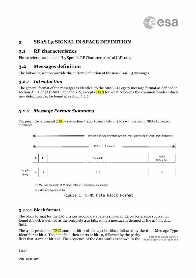
The preamble is changed (TBC – see section 3.2.2.4) from 8 bits to 4 bits with respect to SBAS L1 Legacy messages
Direction of Data flow from satellite; Most significant bit (MSB) transmitted first
250 bits – 1 second
P Id Data field Parity(CRC-24Q)
Length
(bits)4 6 216 24
P = Message preamble of 24 bits in total, in 6 contiguous data blocks
Id = Message Type identifier
Figure 1: DFMC Data Block Format
3.2.2.1 Block formatThe block format for the 250 bits per second data rate is shown in Error: Reference source not found A block is defined as the complete 250 bits, while a message is defined as the 216 bit data field.
The 4-bit preamble (TBC) starts at bit 0 of the 250-bit block followed by the 6-bit Message Type Identifier at bit 4. The data field then starts at bit 10, followed by the parity field that starts at bit 226. The sequence of the data words is shown in the figures describing the message formats while the number of bits per data
Page /
Date Issue Rev
word is given in the tables describing message contents. The order of the words in those tables is not related to the sequence of the words in the message.
Page /
Date Issue Rev
3.2.2.2 Block length and contentBlocks will be 250 bits long (one second), consisting of a 4-bits (TBC) part of a distributed preamble, a 6-bits message type, a 216-bits message and 24 bits of Cyclic Redundancy Check (CRC) parity.
3.2.2.3 ParityThe sequence of 24 parity bits is generated from the information bits (i.e. bits 0 to 225) using the same algorithm as for SBAS L1 Legacy (please refer to section A.4.4.3 of [AD-002]).
3.2.2.4 PreambleThe distributed preamble will be a 24-bit unique word, distributed over six successive blocks. These six 4-bits words (TBC) will be made up of the sequence of bits 0101 0011 1001 1010 1100 0110 (TBC). The start of every other 24-bit preamble will be synchronous with a 6-second GPS sub-frame epoch.
With respect to the convolutional encoding, the preamble is within the decoded bit stream. It will be encoded just like all of the other bits. It is a place marker, and cannot be used for acquisition or encoded bit synchronization prior to convolutional decoding. The users’ convolutional decoding algorithm must provide synchronization to the data bits.
Page /
Date Issue Rev
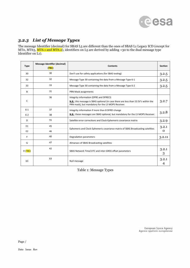
3.2.3 List of Message TypesThe message Identifier (decimal) for SBAS L5 are different than the ones of SBAS L1 Legacy ICD (except for MT0, MT63, MT6.1 and MT6.2), identifiers on L5 are derived by adding +30 to the dual message type Identifier on L1).
TypeMessage Identifier (decimal)
(TBC)Contents Section
30 30 Don't use for safety applications (for SBAS testing) 3.2.5
32 32 Message Type 30 containing the data from a Message Type 6-1 3.2.5
33 33 Message Type 30 containing the data from a Message Type 6-2 3.2.5
B 31 PRN Mask assignments
C36 Integrity information (DFRE and DFRECI)
N.B.: this message is SBAS optional (in case there are less than 53 SV’s within the PRN mask), but mandatory for the L5 MOPS Receiver.
3.2.7
6-1 37 Integrity information if more than 8 DFREI change
N.B.: these messages are SBAS optional, but mandatory for the L5 MOPS Receiver.3.2.8
6-2 38
D 55 Satellite error corrections and Clock-Ephemeris covariance matrix 3.2.9E1 45
Ephemeris and Clock-Ephemeris covariance matrix of SBAS Broadcasting satellites3.2.1
0E2 46
F 40 Degradation parameters 3.2.11
G 47 Almanacs of SBAS Broadcasting satellites
H (TBC)42
SBAS Network Time/UTC and inter-GNSS offset parameters3.2.1
3
6363
Null message3.2.1
4
Table 1: Message Types
Page /
Date Issue Rev
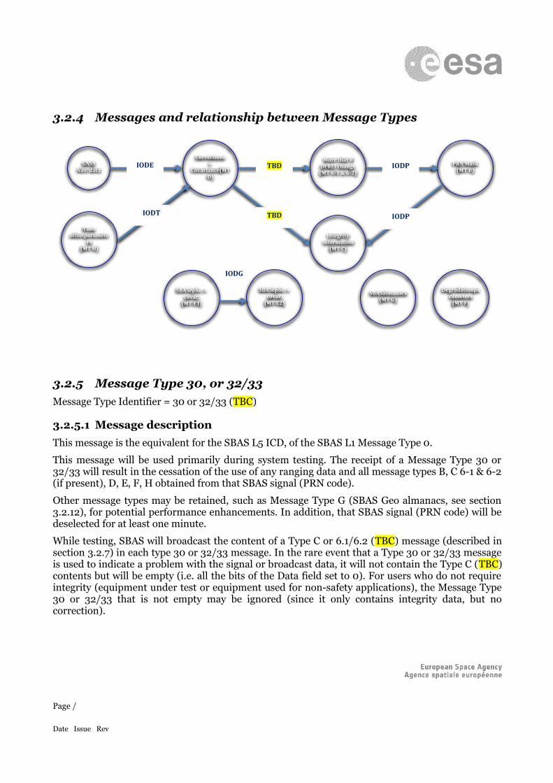
3.2.4 Messages and relationship between Message Types
3.2.5 Message Type 30, or 32/33Message Type Identifier = 30 or 32/33 (TBC)
3.2.5.1 Message descriptionThis message is the equivalent for the SBAS L5 ICD, of the SBAS L1 Message Type 0.
This message will be used primarily during system testing. The receipt of a Message Type 30 or 32/33 will result in the cessation of the use of any ranging data and all message types B, C 6-1 & 6-2 (if present), D, E, F, H obtained from that SBAS signal (PRN code).
Other message types may be retained, such as Message Type G (SBAS Geo almanacs, see section 3.2.12), for potential performance enhancements. In addition, that SBAS signal (PRN code) will be deselected for at least one minute.
While testing, SBAS will broadcast the content of a Type C or 6.1/6.2 (TBC) message (described in section 3.2.7) in each type 30 or 32/33 message. In the rare event that a Type 30 or 32/33 message is used to indicate a problem with the signal or broadcast data, it will not contain the Type C (TBC) contents but will be empty (i.e. all the bits of the Data field set to 0). For users who do not require integrity (equipment under test or equipment used for non-safety applications), the Message Type 30 or 32/33 that is not empty may be ignored (since it only contains integrity data, but no correction).
Page /
Date Issue Rev
IODP
IODPIODE TBD
TBDIODT
SBAS
ephe. + covar.
(MT E1)
Time offset
parameters
(MT H)
Degradation
parameters
(MT F)
SBAS
almanacs
(MT G)
SBAS
ephe. + covar.
(MT E2)
More that 8
DFREI change
(MT 6-1 & 6-2)
Integrity
information
(MT C)
PRN Mask
(MT B)
Corrections
+ Covariance
(MT D)
GNSS
Nav. data
IODG
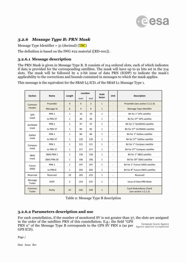
3.2.6 Message Type B: PRN MaskMessage Type Identifier = 31 (decimal) (TBC)
The definition is based on the IWG #22 material ([RD-001]).
3.2.6.1 Message descriptionThe PRN Mask is given in Message Type B. It consists of 214 ordered slots, each of which indicates if data is provided for the corresponding satellites. The mask will have up to 91 bits set in the 214 slots. The mask will be followed by a 2-bit issue of data PRN (IODP) to indicate the mask’s applicability to the corrections and bounds contained in messages to which the mask applies.
This message is the equivalent for the SBAS L5 ICD, of the SBAS L1 Message Type 1.
Section Name LengthLocation Scale
factor Unit Descriptionstart end
CommonHeader
Preamble 4 0 3 1 - Preamble (see section 3.2.2.4)
Message Id. 6 4 9 1 - Message Type Identifier
GPSmask
PRN 1 1 10 10 1 - Bit for 1st GPS satellite
to PRN 37 1 46 46 1 - Bit for 37th GPS satellite
GLONASSmask
PRN 1 1 47 47 1 - Bit for 1st GLONASS satellite
to PRN 37 1 83 83 1 - Bit for 37th GLONASS satellite
Galileomask
PRN 1 1 84 84 1 - Bit for 1st Galileo satellite
to PRN 37 1 120 120 1 - Bit for 37th Galileo satellite
Compassmask
PRN 1 1 121 121 1 - Bit for 1st Compass satellite
to PRN 37 1 157 157 1 - Bit for 37th Compass satellite
SBASmask
SBAS PRN 1 1 158 158 1 - Bit for 1st SBAS satellite
SBAS PRN 39 1 196 196 1 - Bit for 39th SBAS satellite
FutureGNSS
PRN 1 1 197 197 1 - Bit for 1st Future GNSS satellite
to PRN 8 1 204 204 1 - Bit for 8th Future GNSS satellite
Reserved Reserved 19 205 223 1 - Reserved
Message Trailer IODP 2 224 225 1 - Issue of Data PRN Mask
CommonTrailer Parity 24 226 249 1 - Cycle Redundancy Check
(see section 3.2.2.3)
Table 2: Message Type B description
3.2.6.2 Parameters description and useFor each constellation, if the number of monitored SV is not greater than 37, the slots are assigned in the order of the satellites PRN of this constellation; E.g.: the field “GPS PRN n” of the Message Type B corresponds to the GPS SV PRN n (as per GPS ICD).
Page /
Date Issue Rev
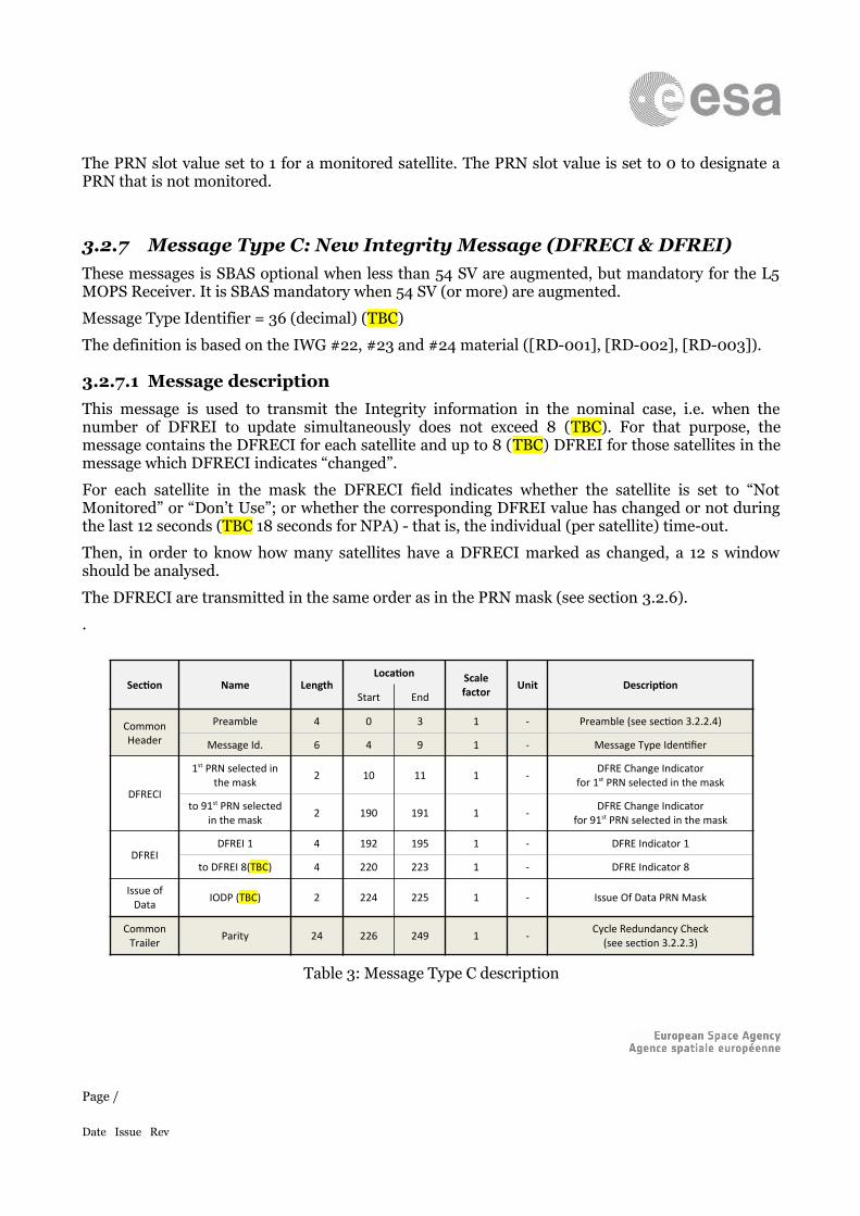
The PRN slot value set to 1 for a monitored satellite. The PRN slot value is set to 0 to designate a PRN that is not monitored.
3.2.7 Message Type C: New Integrity Message (DFRECI & DFREI)These messages is SBAS optional when less than 54 SV are augmented, but mandatory for the L5 MOPS Receiver. It is SBAS mandatory when 54 SV (or more) are augmented.
Message Type Identifier = 36 (decimal) (TBC)
The definition is based on the IWG #22, #23 and #24 material ([RD-001], [RD-002], [RD-003]).
3.2.7.1 Message descriptionThis message is used to transmit the Integrity information in the nominal case, i.e. when the number of DFREI to update simultaneously does not exceed 8 (TBC). For that purpose, the message contains the DFRECI for each satellite and up to 8 (TBC) DFREI for those satellites in the message which DFRECI indicates “changed”.
For each satellite in the mask the DFRECI field indicates whether the satellite is set to “Not Monitored” or “Don’t Use”; or whether the corresponding DFREI value has changed or not during the last 12 seconds (TBC 18 seconds for NPA) - that is, the individual (per satellite) time-out.
Then, in order to know how many satellites have a DFRECI marked as changed, a 12 s window should be analysed.
The DFRECI are transmitted in the same order as in the PRN mask (see section 3.2.6).
.
Section Name LengthLocation Scale
factor Unit DescriptionStart End
CommonHeader
Preamble 4 0 3 1 - Preamble (see section 3.2.2.4)
Message Id. 6 4 9 1 - Message Type Identifier
DFRECI
1st PRN selected in the mask 2 10 11 1 - DFRE Change Indicator
for 1st PRN selected in the mask
to 91st PRN selected in the mask 2 190 191 1 - DFRE Change Indicator
for 91st PRN selected in the mask
DFREIDFREI 1 4 192 195 1 - DFRE Indicator 1
to DFREI 8(TBC) 4 220 223 1 - DFRE Indicator 8
Issue of Data IODP (TBC) 2 224 225 1 - Issue Of Data PRN Mask
CommonTrailer Parity 24 226 249 1 - Cycle Redundancy Check
(see section 3.2.2.3)
Table 3: Message Type C description
Page /
Date Issue Rev
3.2.7.2 Parameters description and useThe IODP parameter in Message Type C allows to link it with the PRN Mask (Message Type B) (see section 3.2.6).
Each 2-bit DFRECI field (i.e. for each satellite defined in the mask) can take the following values:
0 means that DFREI has not changed during the last 12 seconds (TBC 18 seconds for NPA ), that is the individual (per satellite) time-out.
1 means that DFREI value is changed, and that the corresponding new DFREI value is transmitted within the DFREI section of the message. Please note that the number of DFREI values that can be transmitted through a single MT C is limited to 8 (TBC).
2 means that satellite is set to “Not Monitored”
3 means that satellite is set to “Don’t Use”
DFREI values (up to 8 (TBC)) are transmitted for each satellite with a DFRECI value equal to 1.
The DFREI table defining the correspondence between the DFRE Indicator (DFREI) values and the variance values (σDFRE, in metres) is SBAS dependent and is transmitted through Message Type F (see section 3.2.11).
3.2.8 Message Type 6-1/6-2: Integrity message if more than 8 DFREI change
These messages is SBAS optional, but mandatory for the L5 MOPS Receiver.
Message Type Identifier for 6-1 = 37 (decimal) (TBC)
Message Type Identifier for 6-2 = 38 (decimal) (TBC)
The definition is based on the presentation made during IWG #25 preparation meeting held in ESTEC on the 11th of December 2013 ([RD-005]).
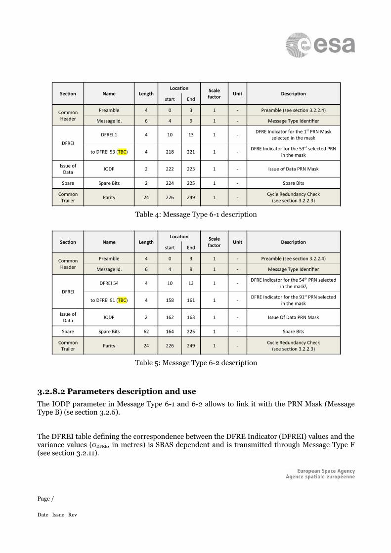
3.2.8.1 Message descriptionThese messages are used to transmit the Integrity information in the rare situations where the number of DFREI to update simultaneously would exceed 8 (TBC). The structure of this message is similar to the one of the SBAS L1 Message Type 6, and contains the DFREI value for each satellite defined in the PRN mask (see section 3.2.6).
Knowing that in the SBAS L5 DFMC standard up to 91 satellites can be selected in the PRN mask, this message is duplicated (MT 6-1 and 6-2).
Page /
Date Issue Rev
Section Name LengthLocation Scale
factor Unit Descriptionstart End
CommonHeader
Preamble 4 0 3 1 - Preamble (see section 3.2.2.4)
Message Id. 6 4 9 1 - Message Type Identifier
DFREI
DFREI 1 4 10 13 1 - DFRE Indicator for the 1st PRN Mask selected in the mask
to DFREI 53 (TBC) 4 218 221 1 - DFRE Indicator for the 53rd selected PRN in the mask
Issue of Data IODP 2 222 223 1 - Issue of Data PRN Mask
Spare Spare Bits 2 224 225 1 - Spare Bits
CommonTrailer Parity 24 226 249 1 - Cycle Redundancy Check
(see section 3.2.2.3)
Table 4: Message Type 6-1 description
Section Name LengthLocation Scale
factor Unit Descriptionstart End
CommonHeader
Preamble 4 0 3 1 - Preamble (see section 3.2.2.4)
Message Id. 6 4 9 1 - Message Type Identifier
DFREI
DFREI 54 4 10 13 1 - DFRE Indicator for the 54th PRN selected in the mask\
to DFREI 91 (TBC) 4 158 161 1 - DFRE Indicator for the 91st PRN selected in the mask
Issue of Data IODP 2 162 163 1 - Issue Of Data PRN Mask
Spare Spare Bits 62 164 225 1 - Spare Bits
CommonTrailer Parity 24 226 249 1 - Cycle Redundancy Check
(see section 3.2.2.3)
Table 5: Message Type 6-2 description
3.2.8.2 Parameters description and useThe IODP parameter in Message Type 6-1 and 6-2 allows to link it with the PRN Mask (Message Type B) (se section 3.2.6).
The DFREI table defining the correspondence between the DFRE Indicator (DFREI) values and the variance values (σDFRE, in metres) is SBAS dependent and is transmitted through Message Type F (see section 3.2.11).
Page /
Date Issue Rev
3.2.9 Message Type D: Long term corrections and Clock-Ephemeris covariance matrix
Message Type Identifier = 55 (decimal) (TBC)
The definition is based on the IWG #22 material ([RD-001]).
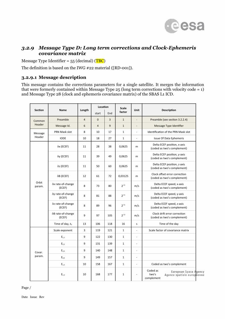
3.2.9.1 Message descriptionThis message contains the corrections parameters for a single satellite. It merges the information that were formerly contained within Message Type 25 (long term corrections with velocity code = 1) and Message Type 28 (clock and ephemeris covariance matrix) of the SBAS L1 ICD.
Section Name LengthLocation Scale
factor Unit Descriptionstart End
CommonHeader
Preamble 4 0 3 1 - Preamble (see section 3.2.2.4)
Message Id. 6 4 9 1 - Message Type Identifier
MessageHeader
PRN Mask slot 8 10 17 1 - Identification of the PRN Mask slot
IODE 10 18 27 1 - Issue Of Data Ephemeris
Orbitparam.
x (ECEF) 11 28 38 0,0625 m Delta ECEF position, x-axis(coded as two's complement)
y (ECEF) 11 39 49 0,0625 m Delta ECEF position, y-axis(coded as two's complement)
z (ECEF) 11 50 60 0,0625 m Delta ECEF position, z-axis(coded as two's complement)
B (ECEF) 12 61 72 0,03125 m Clock offset error correction(coded as two's complement)
x rate-of-change(ECEF) 8 73 80 2-11 m/s Delta ECEF speed, x-axis
(coded as two's complement)
y rate-of-change(ECEF) 8 81 88 2-11 m/s Delta ECEF speed, y-axis
(coded as two's complement)
z rate-of-change(ECEF) 8 89 96 2-11 m/s Delta ECEF speed, z-axis
(coded as two's complement)
B rate-of-change(ECEF) 9 97 105 2-12 m/s Clock drift error correction
(coded as two's complement)
Time of day, t0 13 106 118 16 s Time of the day
Covar. param.
Scale exponent 3 119 121 1 - Scale factor of covariance matrix
E1,1 9 122 130 1 -
E2,2 9 131 139 1 -
E3,3 9 140 148 1 -
E4,4 9 149 157 1 -
E1,2 10 158 167 1 - Coded as two's complement
E1,3 10 168 177 1 -Coded as
two's complement
Page /
Date Issue Rev
Section Name LengthLocation Scale
factor Unit Descriptionstart End
E1,4 10 178 187 1 - Coded as two's complement
E2,3 10 188 197 1 - Coded as two's complement
E2,4 10 198 207 1 - Coded as two's complement
E3,4 10 208 217 1 - Coded as two's complement
Integrityparam. DFREI 4 218 221 1 - Dual Frequency Error Indicator
Issue of Data IODT (TBC) 4 222 225 1 - Issue Of Data Time (MT H)
CommonTrailer Parity 24 226 249 1 - Cycle Redundancy Check
(see section 3.2.2.3)
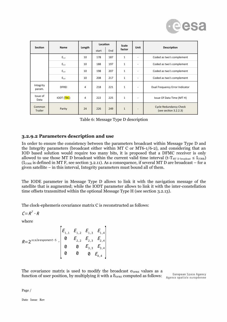
Table 6: Message Type D description
3.2.9.2 Parameters description and useIn order to ensure the consistency between the parameters broadcast within Message Type D and the Integrity parameters (broadcast either within MT C or MT6-1/6-2), and considering that an IOD based solution would require too many bits, it is proposed that a DFMC receiver is only allowed to use those MT D broadcast within the current valid time interval (t-TMT D broadcast ≤ ICORR) (ICORR is defined in MT F, see section 3.2.11). As a consequence, if several MT D are broadcast – for a given satellite – in this interval, Integrity parameters must bound all of them.
The IODE parameter in Message Type D allows to link it with the navigation message of the satellite that is augmented; while the IODT parameter allows to link it with the inter-constellation time offsets transmitted within the optional Message Type H (see section 3.2.13).
The clock-ephemeris covariance matrix C is reconstructed as follows:
C=RT ∙ Rwhere
R=2scale exponent−5 ∙[E1,1 E1,2 E1,3 E1,4
0 E2,2 E2,3 E2,4
00
00
E3,3 E3,4
0 E4,4]
The covariance matrix is used to modify the broadcast σDFRE values as a function of user position, by multiplying it with a δDFRE computed as follows:
δDFRE=√IT ∙C ∙ I+ε c
Page /
Date Issue Rev

Page /
Date Issue Rev
where:
I is the 4-D line of sight vector from the user to the satellite in the WGS-84 coordinate frame, where the first three components are the unit vector from the user to the satellite and the fourth component is a one
C is the clock-ephemeris covariance matrix
εc is derived from Ccovariance (broadcast in Message Type F, described in section 3.2.11) as follows: ε c=Ccovariance ∙2
scale exponent−5
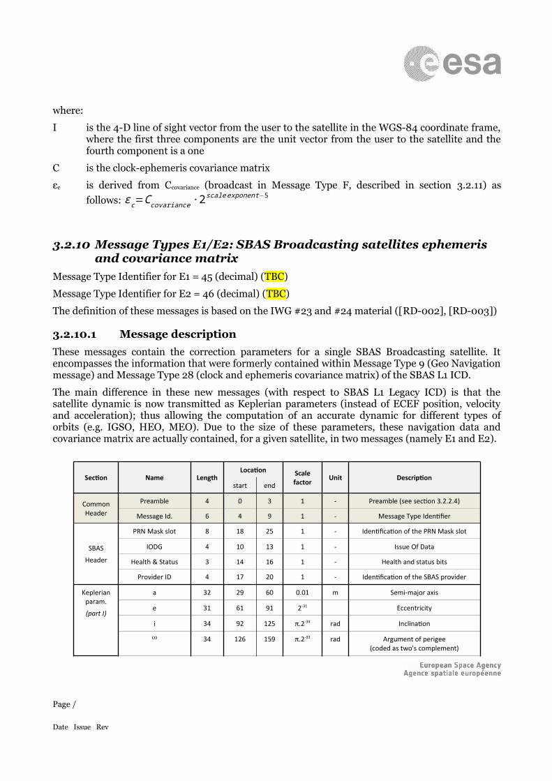
3.2.10 Message Types E1/E2: SBAS Broadcasting satellites ephemeris and covariance matrix
Message Type Identifier for E1 = 45 (decimal) (TBC)
Message Type Identifier for E2 = 46 (decimal) (TBC)
The definition of these messages is based on the IWG #23 and #24 material ([RD-002], [RD-003])
3.2.10.1 Message descriptionThese messages contain the correction parameters for a single SBAS Broadcasting satellite. It encompasses the information that were formerly contained within Message Type 9 (Geo Navigation message) and Message Type 28 (clock and ephemeris covariance matrix) of the SBAS L1 ICD.
The main difference in these new messages (with respect to SBAS L1 Legacy ICD) is that the satellite dynamic is now transmitted as Keplerian parameters (instead of ECEF position, velocity and acceleration); thus allowing the computation of an accurate dynamic for different types of orbits (e.g. IGSO, HEO, MEO). Due to the size of these parameters, these navigation data and covariance matrix are actually contained, for a given satellite, in two messages (namely E1 and E2).
Section Name LengthLocation Scale
factor Unit Descriptionstart end
Common Header
Preamble 4 0 3 1 - Preamble (see section 3.2.2.4)
Message Id. 6 4 9 1 - Message Type Identifier
SBAS
Header
PRN Mask slot 8 18 25 1 - Identification of the PRN Mask slot
IODG 4 10 13 1 - Issue Of Data
Health & Status 3 14 16 1 - Health and status bits
Provider ID 4 17 20 1 - Identification of the SBAS provider
Keplerian param.
(part I)
a 32 29 60 0.01 m Semi-major axis
e 31 61 91 2-31 Eccentricity
i 34 92 125 π.2-34 rad Inclination
34 126 159 π.2-33 rad Argument of perigee(coded as two's complement)
Page /
Date Issue Rev
Section Name LengthLocation Scale
factor Unit Descriptionstart end
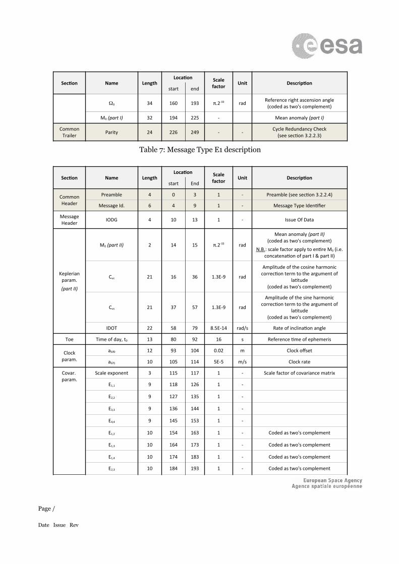
0 34 160 193 π.2-33 rad Reference right ascension angle(coded as two's complement)
M0 (part I) 32 194 225 - Mean anomaly (part I)
Common Trailer Parity 24 226 249 - - Cycle Redundancy Check
(see section 3.2.2.3)
Table 7: Message Type E1 description
Section Name LengthLocation Scale
factor Unit Descriptionstart End
CommonHeader
Preamble 4 0 3 1 - Preamble (see section 3.2.2.4)
Message Id. 6 4 9 1 - Message Type Identifier
MessageHeader IODG 4 10 13 1 - Issue Of Data
Keplerian param.
(part II)
M0 (part II) 2 14 15 π.2-33 rad
Mean anomaly (part II)(coded as two's complement)
N.B.: scale factor apply to entire M0 (i.e. concatenation of part I & part II)
Cuc 21 16 36 1.3E-9 rad
Amplitude of the cosine harmonic correction term to the argument of
latitude(coded as two's complement)
Cus 21 37 57 1.3E-9 rad
Amplitude of the sine harmonic correction term to the argument of
latitude(coded as two's complement)
IDOT 22 58 79 8.5E-14 rad/s Rate of inclination angle
Toe Time of day, t0 13 80 92 16 s Reference time of ephemeris
Clock param.
aGf0 12 93 104 0.02 m Clock offset
aGf1 10 105 114 5E-5 m/s Clock rate
Covar. param.
Scale exponent 3 115 117 1 - Scale factor of covariance matrix
E1,1 9 118 126 1 -
E2,2 9 127 135 1 -
E3,3 9 136 144 1 -
E4,4 9 145 153 1 -
E1,2 10 154 163 1 - Coded as two's complement
E1,3 10 164 173 1 - Coded as two's complement
E1,4 10 174 183 1 - Coded as two's complement
E2,3 10 184 193 1 - Coded as two's complement
Page /
Date Issue Rev
Section Name LengthLocation Scale
factor Unit Descriptionstart End
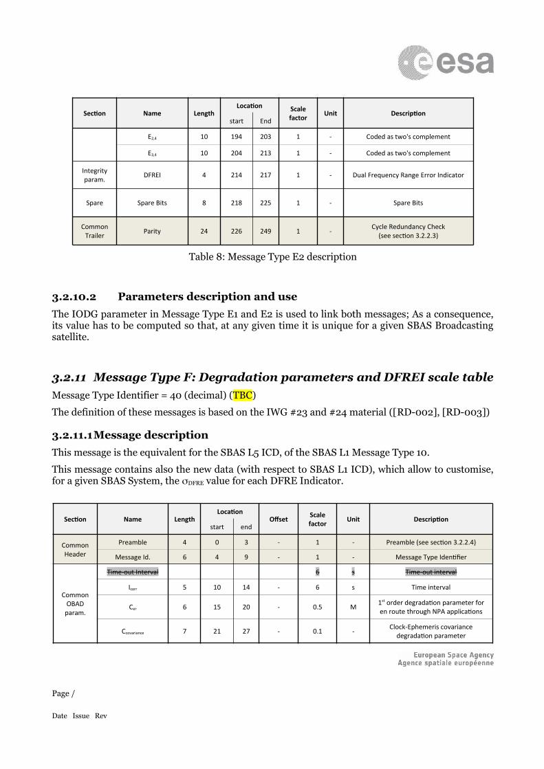
E2,4 10 194 203 1 - Coded as two's complement
E3,4 10 204 213 1 - Coded as two's complement
Integrityparam. DFREI 4 214 217 1 - Dual Frequency Range Error Indicator
Spare Spare Bits 8 218 225 1 - Spare Bits
CommonTrailer Parity 24 226 249 1 - Cycle Redundancy Check
(see section 3.2.2.3)
Table 8: Message Type E2 description
3.2.10.2 Parameters description and useThe IODG parameter in Message Type E1 and E2 is used to link both messages; As a consequence, its value has to be computed so that, at any given time it is unique for a given SBAS Broadcasting satellite.
3.2.11 Message Type F: Degradation parameters and DFREI scale tableMessage Type Identifier = 40 (decimal) (TBC)
The definition of these messages is based on the IWG #23 and #24 material ([RD-002], [RD-003])
3.2.11.1Message descriptionThis message is the equivalent for the SBAS L5 ICD, of the SBAS L1 Message Type 10.
This message contains also the new data (with respect to SBAS L1 ICD), which allow to customise, for a given SBAS System, the DFRE value for each DFRE Indicator.
Section Name LengthLocation
Offset Scalefactor Unit Description
start end
CommonHeader
Preamble 4 0 3 - 1 - Preamble (see section 3.2.2.4)
Message Id. 6 4 9 - 1 - Message Type Identifier
CommonOBAD
param.
Time-out Interval 6 s Time-out interval
Icorr 5 10 14 - 6 s Time interval
Cer 6 15 20 - 0.5 M 1st order degradation parameter for en route through NPA applications
Ccovariance 7 21 27 - 0.1 - Clock-Ephemeris covariance degradation parameter
Page /
Date Issue Rev
Section Name LengthLocation
Offset Scalefactor Unit Description
start end
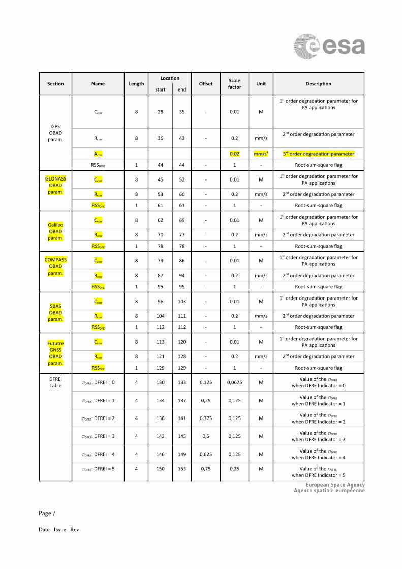
GPSOBAD
param.
Ccorr 8 28 35 - 0.01 M
1st order degradation parameter for PA applications
Rcorr 8 36 43 - 0.2 mm/s 2nd order degradation parameter
Acorr 0.02 mm/s2 3rd order degradation parameter
RSSDFRE 1 44 44 - 1 - Root-sum-square flag
GLONASSOBAD
param.
Ccorr 8 45 52 - 0.01 M 1st order degradation parameter for PA applications
Rcorr 8 53 60 - 0.2 mm/s 2nd order degradation parameter
RSSDFC 1 61 61 - 1 - Root-sum-square flag
GalileoOBAD
param.
Ccorr 8 62 69 - 0.01 M 1st order degradation parameter for PA applications
Rcorr 8 70 77 - 0.2 mm/s 2nd order degradation parameter
RSSDFC 1 78 78 - 1 - Root-sum-square flag
COMPASSOBAD
param.
Ccorr 8 79 86 - 0.01 M 1st order degradation parameter for PA applications
Rcorr 8 87 94 - 0.2 mm/s 2nd order degradation parameter
RSSDFC 1 95 95 - 1 - Root-sum-square flag
SBASOBAD
param.
Ccorr 8 96 103 - 0.01 M 1st order degradation parameter for PA applications
Rcorr 8 104 111 - 0.2 mm/s 2nd order degradation parameter
RSSDFC 1 112 112 - 1 - Root-sum-square flag
FututreGNSSOBAD
param.
Ccorr 8 113 120 - 0.01 M 1st order degradation parameter for PA applications
Rcorr 8 121 128 - 0.2 mm/s 2nd order degradation parameter
RSSDFC 1 129 129 - 1 - Root-sum-square flag
DFREITable DFRE: DFREI = 0 4 130 133 0,125 0,0625 M Value of the DFRE
when DFRE Indicator = 0
DFRE: DFREI = 1 4 134 137 0,25 0,125 M Value of the DFRE
when DFRE Indicator = 1
DFRE: DFREI = 2 4 138 141 0,375 0,125 M Value of the DFRE
when DFRE Indicator = 2
DFRE: DFREI = 3 4 142 145 0,5 0,125 M Value of the DFRE
when DFRE Indicator = 3
DFRE: DFREI = 4 4 146 149 0,625 0,125 M Value of the DFRE
when DFRE Indicator = 4
DFRE: DFREI = 5 4 150 153 0,75 0,25 M Value of the DFRE
when DFRE Indicator = 5
Page /
Date Issue Rev
Section Name LengthLocation
Offset Scalefactor Unit Description
start end
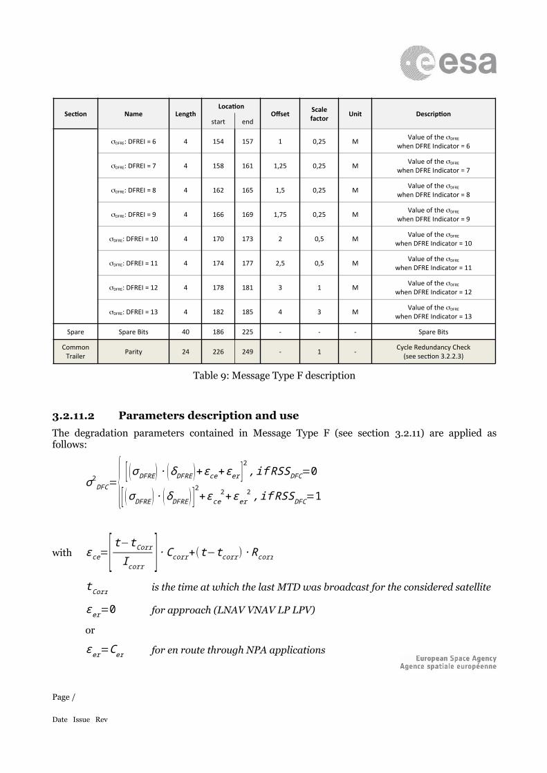
DFRE: DFREI = 6 4 154 157 1 0,25 M Value of the DFRE
when DFRE Indicator = 6
DFRE: DFREI = 7 4 158 161 1,25 0,25 M Value of the DFRE
when DFRE Indicator = 7
DFRE: DFREI = 8 4 162 165 1,5 0,25 M Value of the DFRE
when DFRE Indicator = 8
DFRE: DFREI = 9 4 166 169 1,75 0,25 M Value of the DFRE
when DFRE Indicator = 9
DFRE: DFREI = 10 4 170 173 2 0,5 M Value of the DFRE
when DFRE Indicator = 10
DFRE: DFREI = 11 4 174 177 2,5 0,5 M Value of the DFRE
when DFRE Indicator = 11
DFRE: DFREI = 12 4 178 181 3 1 M Value of the DFRE
when DFRE Indicator = 12
DFRE: DFREI = 13 4 182 185 4 3 M Value of the DFRE
when DFRE Indicator = 13
Spare Spare Bits 40 186 225 - - - Spare Bits
CommonTrailer Parity 24 226 249 - 1 - Cycle Redundancy Check
(see section 3.2.2.3)
Table 9: Message Type F description
3.2.11.2 Parameters description and useThe degradation parameters contained in Message Type F (see section 3.2.11) are applied as follows:
σ 2DFC={ [ (σ DFRE )∙ (δDFRE)+εce+ε er ]
2, if RSSDFC=0
[ (σ DFRE ) ∙ (δDFRE ) ]2+ε ce2+εer2 , if RSSDFC=1
with ε ce=[ t−tCorrI corr ] ∙Ccorr+(t−t corr) ∙R corr
tCorr is the time at which the last MTD was broadcast for the considered satellite
ε er=0 for approach (LNAV VNAV LP LPV)
or
ε er=Cer for en route through NPA applications
For each DFRE Indicator (DFREI), the corresponding DFRE value (m) is computed from each field value as follows:
Page /
Date Issue Rev
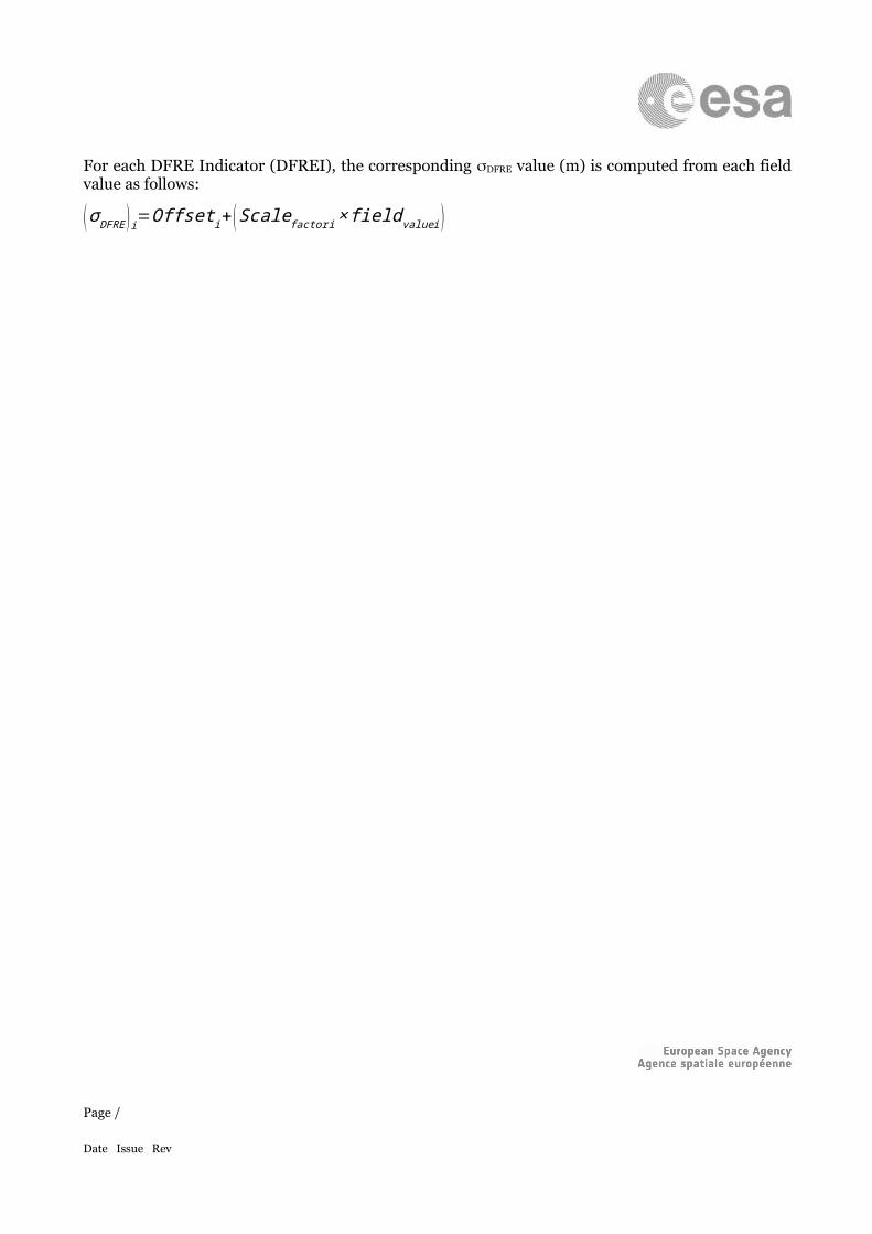
(σ DFRE )i=Offset i+ (Scale factori× fieldvaluei )
Page /
Date Issue Rev
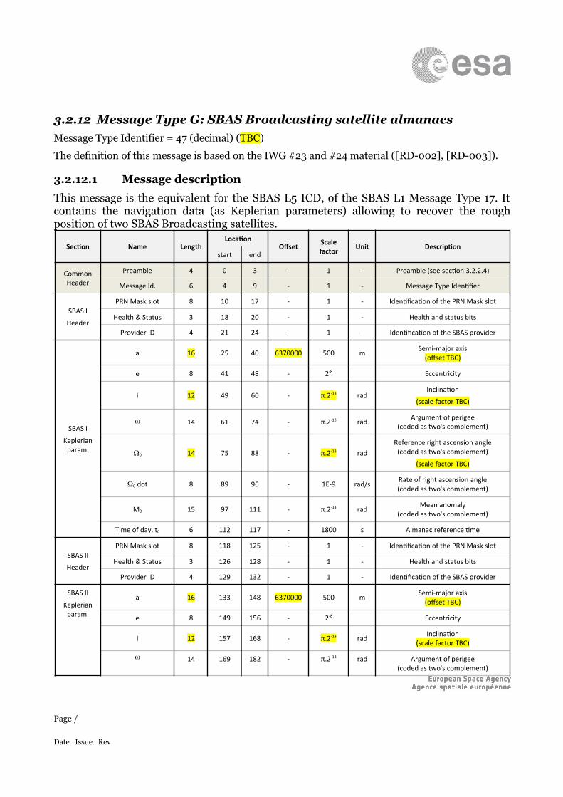
3.2.12 Message Type G: SBAS Broadcasting satellite almanacsMessage Type Identifier = 47 (decimal) (TBC)
The definition of this message is based on the IWG #23 and #24 material ([RD-002], [RD-003]).
3.2.12.1 Message description
This message is the equivalent for the SBAS L5 ICD, of the SBAS L1 Message Type 17. It contains the navigation data (as Keplerian parameters) allowing to recover the rough position of two SBAS Broadcasting satellites.
Section Name LengthLocation
Offset Scalefactor Unit Description
start end
Common Header
Preamble 4 0 3 - 1 - Preamble (see section 3.2.2.4)
Message Id. 6 4 9 - 1 - Message Type Identifier
SBAS I
Header
PRN Mask slot 8 10 17 - 1 - Identification of the PRN Mask slot
Health & Status 3 18 20 - 1 - Health and status bits
Provider ID 4 21 24 - 1 - Identification of the SBAS provider
SBAS I
Keplerian param.
a 16 25 40 6370000 500 m Semi-major axis(offset TBC)
e 8 41 48 - 2-8 Eccentricity
i 12 49 60 - π.2-13 radInclination
(scale factor TBC)
14 61 74 - π.2-13 rad Argument of perigee(coded as two's complement)
0 14 75 88 - π.2-13 radReference right ascension angle
(coded as two's complement)
(scale factor TBC)
0 dot 8 89 96 - 1E-9 rad/s Rate of right ascension angle(coded as two's complement)
M0 15 97 111 - π.2-14 rad Mean anomaly(coded as two's complement)
Time of day, t0 6 112 117 - 1800 s Almanac reference time
SBAS II
Header
PRN Mask slot 8 118 125 - 1 - Identification of the PRN Mask slot
Health & Status 3 126 128 - 1 - Health and status bits
Provider ID 4 129 132 - 1 - Identification of the SBAS provider
SBAS II
Keplerian param.
a 16 133 148 6370000 500 m Semi-major axis(offset TBC)
e 8 149 156 - 2-8 Eccentricity
i 12 157 168 - π.2-13 rad Inclination(scale factor TBC)
14 169 182 - π.2-13 rad Argument of perigee(coded as two's complement)
Page /
Date Issue Rev
Section Name LengthLocation
Offset Scalefactor Unit Description
start end
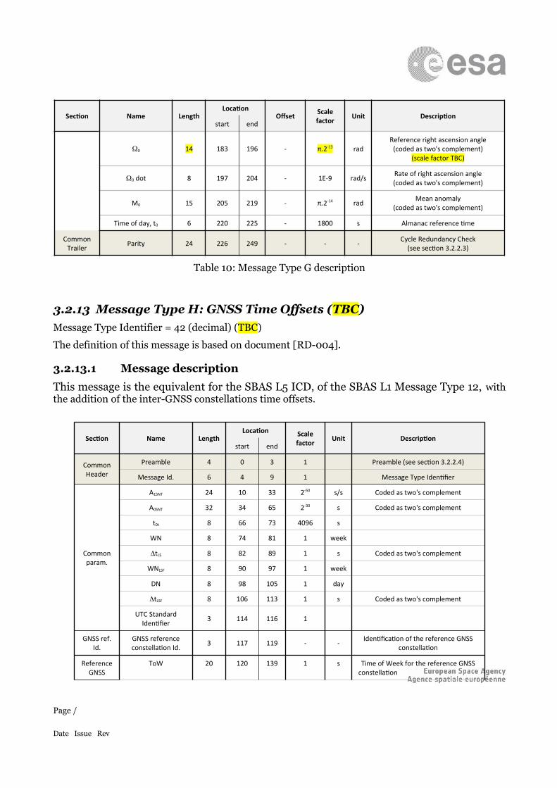
0 14 183 196 - π.2-13 radReference right ascension angle
(coded as two's complement)(scale factor TBC)
0 dot 8 197 204 - 1E-9 rad/s Rate of right ascension angle(coded as two's complement)
M0 15 205 219 - π.2-14 rad Mean anomaly(coded as two's complement)
Time of day, t0 6 220 225 - 1800 s Almanac reference time
Common Trailer Parity 24 226 249 - - - Cycle Redundancy Check
(see section 3.2.2.3)
Table 10: Message Type G description
3.2.13 Message Type H: GNSS Time Offsets (TBC)Message Type Identifier = 42 (decimal) (TBC)
The definition of this message is based on document [RD-004].
3.2.13.1 Message description
This message is the equivalent for the SBAS L5 ICD, of the SBAS L1 Message Type 12, with the addition of the inter-GNSS constellations time offsets.
Section Name LengthLocation Scale
factor Unit Descriptionstart end
Common Header
Preamble 4 0 3 1 Preamble (see section 3.2.2.4)
Message Id. 6 4 9 1 Message Type Identifier
Commonparam.
A1SNT 24 10 33 2-50 s/s Coded as two's complement
A0SNT 32 34 65 2-30 s Coded as two's complement
t0t 8 66 73 4096 s
WN 8 74 81 1 week
tLS 8 82 89 1 s Coded as two's complement
WNLSF 8 90 97 1 week
DN 8 98 105 1 day
tLSF 8 106 113 1 s Coded as two's complement
UTC Standard Identifier 3 114 116 1
GNSS ref. Id.
GNSS reference constellation Id. 3 117 119 - - Identification of the reference GNSS
constellation
Reference GNSS
ToW 20 120 139 1 s Time of Week for the reference GNSS constellation
Page /
Date Issue Rev
Section Name LengthLocation Scale
factor Unit Descriptionstart end
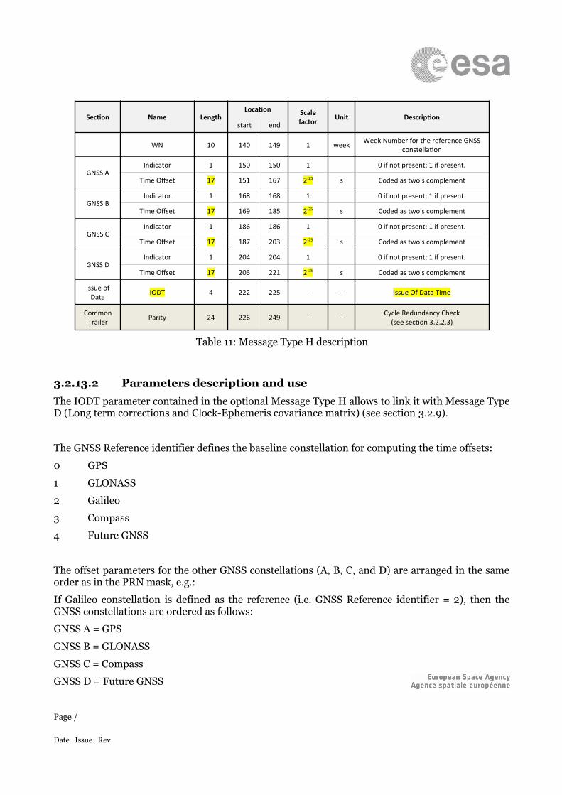
WN 10 140 149 1 week Week Number for the reference GNSS constellation
GNSS AIndicator 1 150 150 1 0 if not present; 1 if present.
Time Offset 17 151 167 2-25 s Coded as two's complement
GNSS BIndicator 1 168 168 1 0 if not present; 1 if present.
Time Offset 17 169 185 2-25 s Coded as two's complement
GNSS CIndicator 1 186 186 1 0 if not present; 1 if present.
Time Offset 17 187 203 2-25 s Coded as two's complement
GNSS DIndicator 1 204 204 1 0 if not present; 1 if present.
Time Offset 17 205 221 2-25 s Coded as two's complement
Issue of Data IODT 4 222 225 - - Issue Of Data Time
Common Trailer Parity 24 226 249 - - Cycle Redundancy Check
(see section 3.2.2.3)
Table 11: Message Type H description
3.2.13.2 Parameters description and useThe IODT parameter contained in the optional Message Type H allows to link it with Message Type D (Long term corrections and Clock-Ephemeris covariance matrix) (see section 3.2.9).
The GNSS Reference identifier defines the baseline constellation for computing the time offsets:
0 GPS
1 GLONASS
2 Galileo
3 Compass
4 Future GNSS
The offset parameters for the other GNSS constellations (A, B, C, and D) are arranged in the same order as in the PRN mask, e.g.:
If Galileo constellation is defined as the reference (i.e. GNSS Reference identifier = 2), then the GNSS constellations are ordered as follows:
GNSS A = GPS
GNSS B = GLONASS
GNSS C = Compass
GNSS D = Future GNSS
Page /
Date Issue Rev
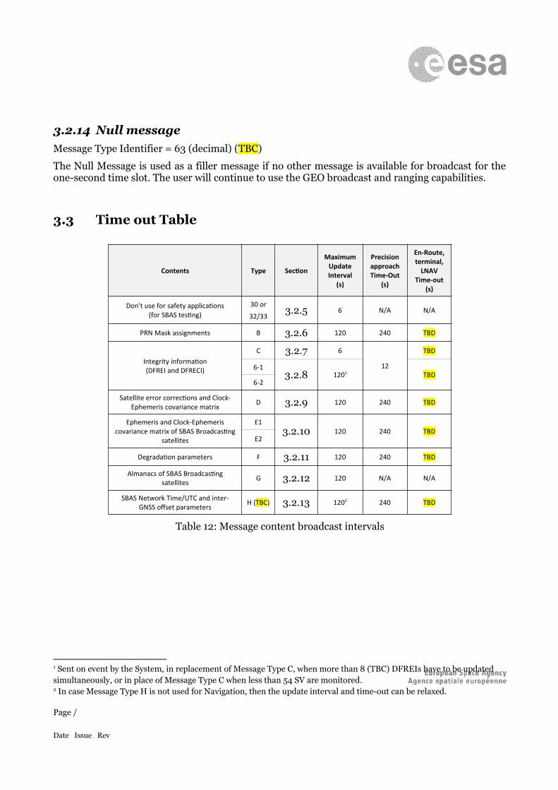
3.2.14 Null messageMessage Type Identifier = 63 (decimal) (TBC)
The Null Message is used as a filler message if no other message is available for broadcast for the one-second time slot. The user will continue to use the GEO broadcast and ranging capabilities.
3.3 Time out Table
Contents Type Section
Maximum Update Interval
(s)
Precision approach Time-Out
(s)
En-Route, terminal,
LNAV Time-out
(s)
Don't use for safety applications(for SBAS testing)
30 or
32/333.2.5 6 N/A N/A
PRN Mask assignments B 3.2.6 120 240 TBD
Integrity information(DFREI and DFRECI)
C 3.2.7 6
12
TBD
6-13.2.8 1201 TBD
6-2
Satellite error corrections and Clock-Ephemeris covariance matrix D 3.2.9 120 240 TBD
Ephemeris and Clock-Ephemeris covariance matrix of SBAS Broadcasting
satellites
E13.2.10 120 240 TBD
E2
Degradation parameters F 3.2.11 120 240 TBD
Almanacs of SBAS Broadcasting satellites G 3.2.12 120 N/A N/A
SBAS Network Time/UTC and inter-GNSS offset parameters H (TBC) 3.2.13 1202 240 TBD
Table 12: Message content broadcast intervals
1 Sent on event by the System, in replacement of Message Type C, when more than 8 (TBC) DFREIs have to be updated simultaneously, or in place of Message Type C when less than 54 SV are monitored.2 In case Message Type H is not used for Navigation, then the update interval and time-out can be relaxed.
Page /
Date Issue Rev
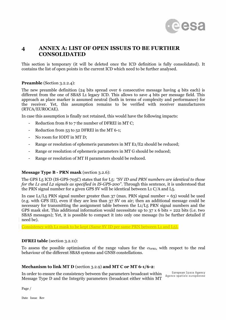
4 ANNEX A: LIST OF OPEN ISSUES TO BE FURTHER CONSOLIDATED
This section is temporary (it will be deleted once the ICD definition is fully consolidated). It contains the list of open points in the current ICD which need to be further analysed.
Preamble (Section 3.2.2.4):
The new preamble definition (24 bits spread over 6 consecutive message having 4 bits each) is different from the one of SBAS L1 legacy ICD. This allows to save 4 bits per message field. This approach as place marker is assumed neutral (both in terms of complexity and performance) for the receiver. Yet, this assumption remains to be verified with receiver manufacturers (RTCA/EUROCAE).
In case this assumption is finally not retained, this would have the following impacts:
- Reduction from 8 to 7 the number of DFREI in MT C;
- Reduction from 53 to 52 DFREI in the MT 6-1;
- No room for IODT in MT D;
- Range or resolution of ephemeris parameters in MT E1/E2 should be reduced;
- Range or resolution of ephemeris parameters in MT G should be reduced;
- Range or resolution of MT H parameters should be reduced.
Message Type B - PRN mask (section 3.2.6):
The GPS L5 ICD (IS-GPS-705C) states that for L5: “SV ID and PRN numbers are identical to those for the L1 and L2 signals as specified in IS-GPS-200”. Through this sentence, it is understood that the PRN signal number for a given GPS SV will be identical between L1 C/A and L5.
In case L1/L5 PRN signal number greater than 37 (max. PRN signal number = 63) would be used (e.g. with GPS III), even if they are less than 37 SV on air; then an additional message could be necessary for transmitting the assignment table between the L1/L5 PRN signal numbers and the GPS mask slot. This additional information would necessitate up to 37 x 6 bits = 222 bits (i.e. two SBAS messages); Yet, it is possible to compact it into only one message (to be further detailed if need be).
Consistency with L1 mask to be kept (Same SV ID per same PRN between L1 and L5).
DFREI table (section 3.2.11):
To assess the possible optimisation of the range values for the DFRE, with respect to the real behaviour of the different SBAS systems and GNSS constellations.
Mechanism to link MT D (section 3.2.9) and MT C or MT 6-1/6-2:
In order to ensure the consistency between the parameters broadcast within Message Type D and the Integrity parameters (broadcast either within MT
Page /
Date Issue Rev
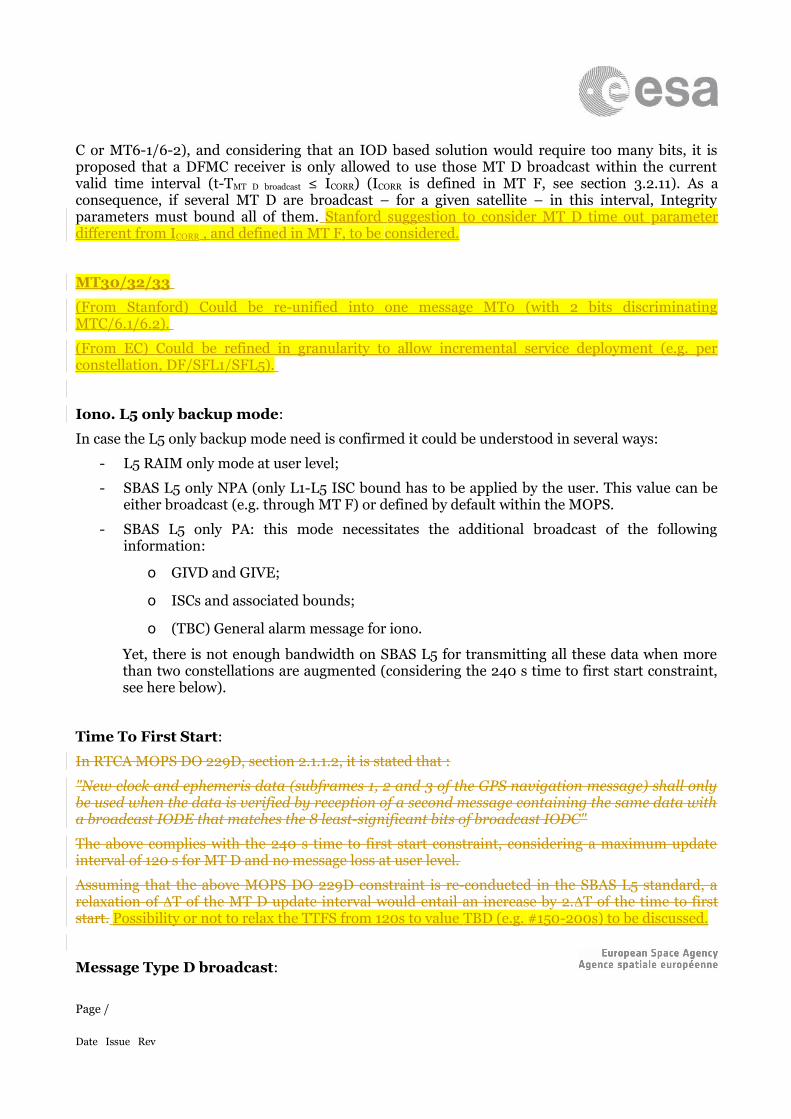
C or MT6-1/6-2), and considering that an IOD based solution would require too many bits, it is proposed that a DFMC receiver is only allowed to use those MT D broadcast within the current valid time interval (t-TMT D broadcast ≤ ICORR) (ICORR is defined in MT F, see section 3.2.11). As a consequence, if several MT D are broadcast – for a given satellite – in this interval, Integrity parameters must bound all of them. Stanford suggestion to consider MT D time out parameter different from ICORR , and defined in MT F, to be considered.
MT30/32/33
(From Stanford) Could be re-unified into one message MT0 (with 2 bits discriminating MTC/6.1/6.2).
(From EC) Could be refined in granularity to allow incremental service deployment (e.g. per constellation, DF/SFL1/SFL5).
Iono. L5 only backup mode:
In case the L5 only backup mode need is confirmed it could be understood in several ways:
- L5 RAIM only mode at user level;
- SBAS L5 only NPA (only L1-L5 ISC bound has to be applied by the user. This value can be either broadcast (e.g. through MT F) or defined by default within the MOPS.
- SBAS L5 only PA: this mode necessitates the additional broadcast of the following information:
o GIVD and GIVE;
o ISCs and associated bounds;
o (TBC) General alarm message for iono.
Yet, there is not enough bandwidth on SBAS L5 for transmitting all these data when more than two constellations are augmented (considering the 240 s time to first start constraint, see here below).
Time To First Start:
In RTCA MOPS DO 229D, section 2.1.1.2, it is stated that :
"New clock and ephemeris data (subframes 1, 2 and 3 of the GPS navigation message) shall only be used when the data is verified by reception of a second message containing the same data with a broadcast IODE that matches the 8 least-significant bits of broadcast IODC"
The above complies with the 240 s time to first start constraint, considering a maximum update interval of 120 s for MT D and no message loss at user level.
Assuming that the above MOPS DO 229D constraint is re-conducted in the SBAS L5 standard, a relaxation of T of the MT D update interval would entail an increase by 2.T of the time to first start. Possibility or not to relax the TTFS from 120s to value TBD (e.g. #150-200s) to be discussed.
Message Type D broadcast:
Page /
Date Issue Rev
By default, the bandwidth budgets have been computed considering that satellite corrections and covariance matrix (MT D) are broadcast for all the satellites defined within the mask (MT B).
Yet, a significant amount of bandwidth could be saved if corrections and covariance matrix were only broadcast for those satellites actually visible from the SBAS service area.
As a consequence, it is recommended that this choice (to broadcast or not the corrections and covariance matrix for the satellites not visible from the service area) is left to each SBAS designer/Service provider.
Message Type D “rate of change” fields:
- The “rate of change” fields in Message Type D are expected to be rarely set to non-null value by SBAS. Hence it could be possible to add one velocity code bit (e.g. taking 1 bit from IODT) to indicate whether these fields are actually used (i.e. for transmitting non-null rate of change), or whether the free bits contain another information TBD.
- According to formula ε ce=[ t−tCorrI corr ] ∙Ccorr+(t−t corr) ∙R corr the ramp term of degradation
applies to all SV whatever the rate of change values are (incl. for null rate of change). In MOPS DO229 D Message Type 25 was containing a velocity code bit allowing to apply a different degradation formula (with no ramp term) for those SV having a null rate of change. To keep this capability for SBAS L5 standard 2 possible solutions could be envisaged:
o Either to add a velocity code bit (e.g. taking 1 bit from IODT) in Message Type D;
o Or to apply the ramp term of degradation only when rate of change is not null.
Message Type H:
Optionally, unlike Message Type 12 in MOPS DO 229D, Message Type H can be used by SBAS as a navigation message to compensate the GNSS constellations time offset with respect to one constellation (considered as reference by the SBAS Service Provider). For this purpose an IODT allows to link Message Type H and Message Type D.
OBAD:
It is proposed to suppress the ACORR parameter in MT F (section 3.2.11), considering that:
- quadratic propagation of clock error is over-pessimistic (see [RD-003]);
- it gives room for per-constellation degradation parameters in MT F.
Optional messages:
SV in mask ≤ 53 SV in mask ≥ 54
Page /
Date Issue Rev
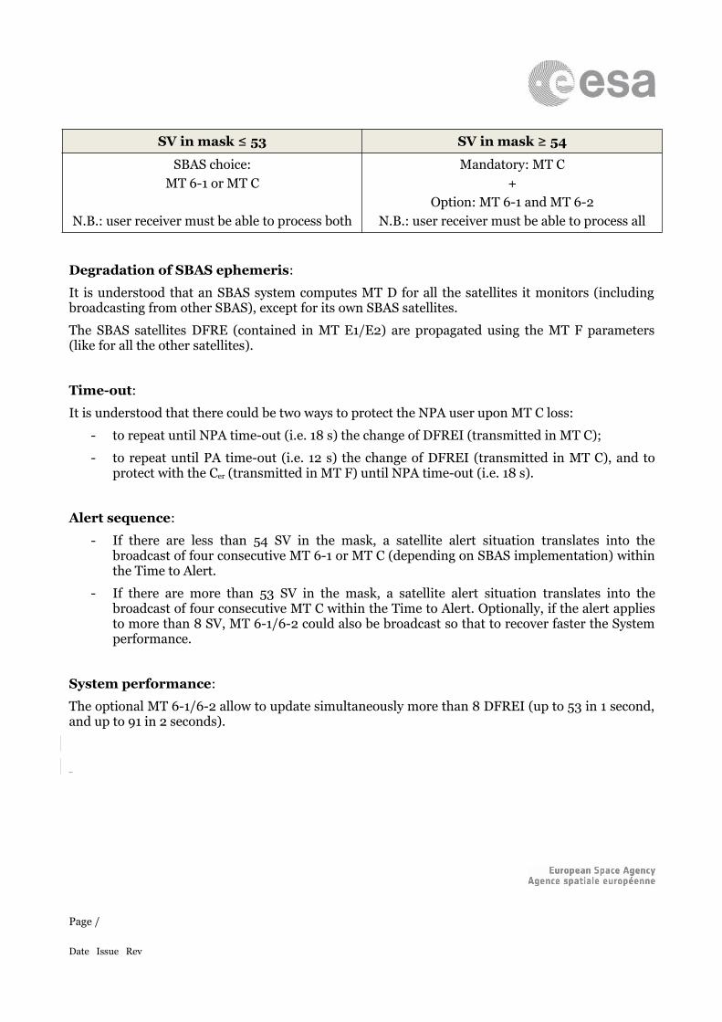
SBAS choice:MT 6-1 or MT C
N.B.: user receiver must be able to process both
Mandatory: MT C+
Option: MT 6-1 and MT 6-2N.B.: user receiver must be able to process all
Degradation of SBAS ephemeris:
It is understood that an SBAS system computes MT D for all the satellites it monitors (including broadcasting from other SBAS), except for its own SBAS satellites.
The SBAS satellites DFRE (contained in MT E1/E2) are propagated using the MT F parameters (like for all the other satellites).
Time-out:
It is understood that there could be two ways to protect the NPA user upon MT C loss:
- to repeat until NPA time-out (i.e. 18 s) the change of DFREI (transmitted in MT C);
- to repeat until PA time-out (i.e. 12 s) the change of DFREI (transmitted in MT C), and to protect with the Cer (transmitted in MT F) until NPA time-out (i.e. 18 s).
Alert sequence:
- If there are less than 54 SV in the mask, a satellite alert situation translates into the broadcast of four consecutive MT 6-1 or MT C (depending on SBAS implementation) within the Time to Alert.
- If there are more than 53 SV in the mask, a satellite alert situation translates into the broadcast of four consecutive MT C within the Time to Alert. Optionally, if the alert applies to more than 8 SV, MT 6-1/6-2 could also be broadcast so that to recover faster the System performance.
System performance:
The optional MT 6-1/6-2 allow to update simultaneously more than 8 DFREI (up to 53 in 1 second, and up to 91 in 2 seconds).
Page /
Date Issue Rev