dr. alexander walsch [email protected] part iv ws ... · technical university munich (tum)...
TRANSCRIPT

Industrial Embedded Systems
- Design for Harsh Environment -
Dr. Alexander [email protected]
Part IV
WS 2011/12
Technical University Munich (TUM)

Case Study
Slide2A. Walsch, IN2244 WS 2012/13
An electronics component that measures pressure in an industrialenvironment is to be developed. It connects to our series of 4-20 mApressure sensors, does a temperature compensation, andcommunicates the value via a CAN interface. We are part of the development team that designs this component (ME, EE, CS). The component is referred to as PMU (Pressure Measurment Unit).
Pressure
SensorPMU CAN
PMU Requirements Analysis
Slide3A. Walsch, IN2244 WS 2012/13
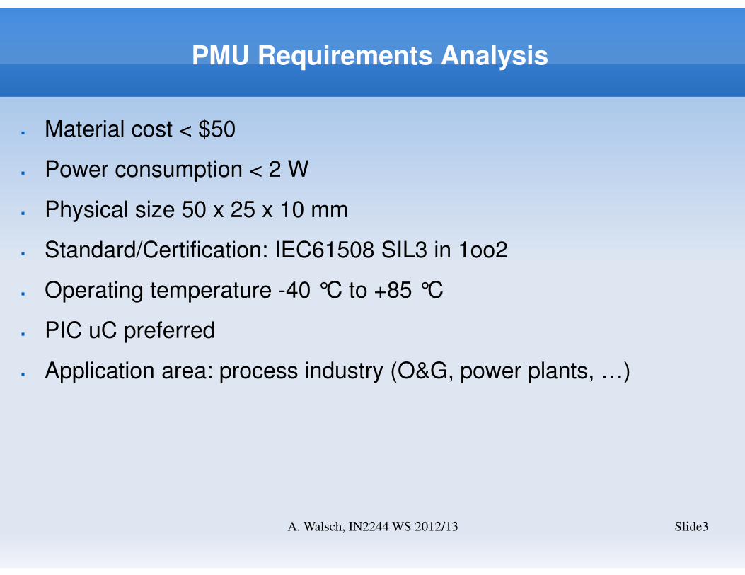
� Material cost < $50
� Power consumption < 2 W
� Physical size 50 x 25 x 10 mm
� Standard/Certification: IEC61508 SIL3 in 1oo2
� Operating temperature -40 °C to +85 °C
� PIC uC preferred
� Application area: process industry (O&G, power plants, …)
PMU Requirements Analysis II
Slide4A. Walsch, IN2244 WS 2012/13
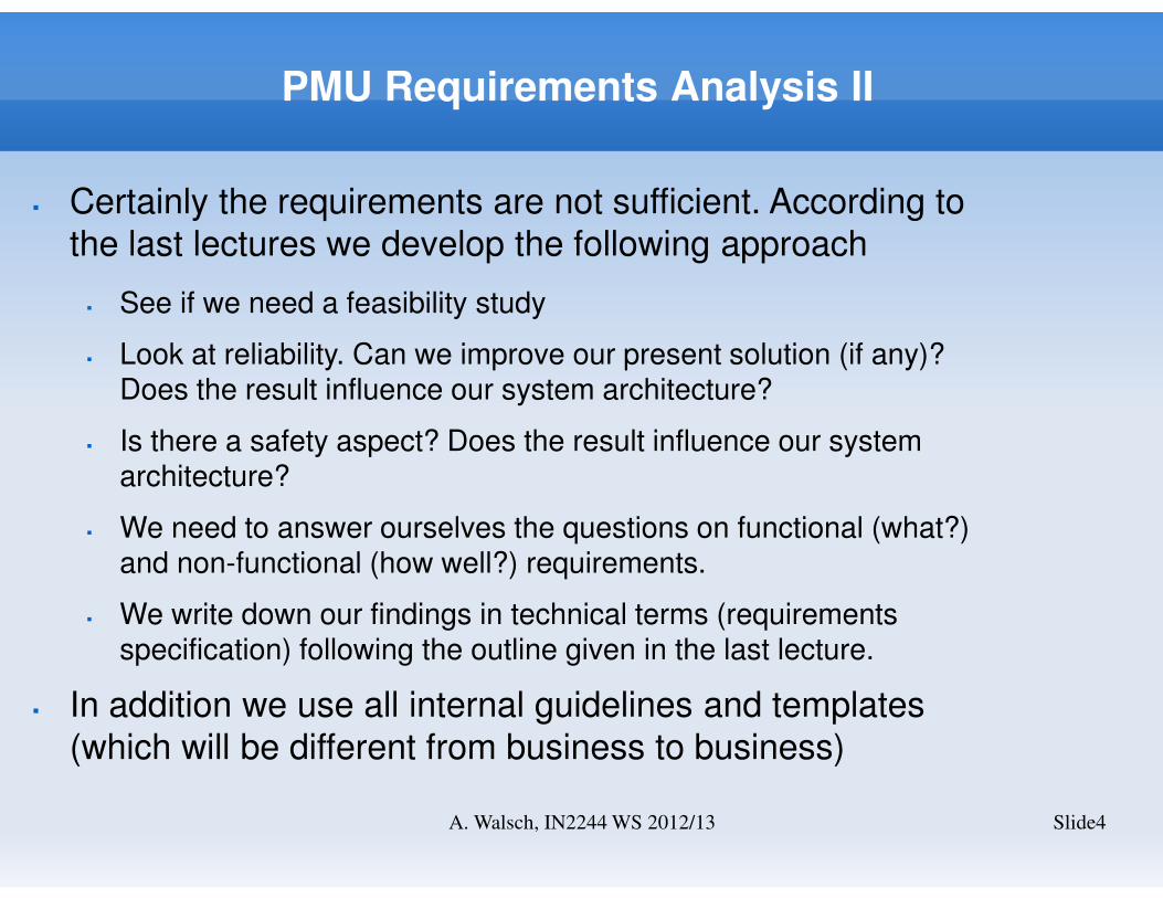
� Certainly the requirements are not sufficient. According to the last lectures we develop the following approach
� See if we need a feasibility study
� Look at reliability. Can we improve our present solution (if any)? Does the result influence our system architecture?
� Is there a safety aspect? Does the result influence our system architecture?
� We need to answer ourselves the questions on functional (what?) and non-functional (how well?) requirements.
� We write down our findings in technical terms (requirements specification) following the outline given in the last lecture.
� In addition we use all internal guidelines and templates (which will be different from business to business)

PMU Reliability
� First we look into a simplex system according to the high level description we have received internally
� We assume reliability metrics from experience or literature.
� We still work at the system border.
Slide5A. Walsch, IN2244 WS 2012/13
MTBF_Power = 2aMTBF_Pressure = 50aMTBF_Temp=50a
MTBF_Control=150aMTBF_CAN=20a
CANControlTemperaturePressurePower
ReliaSoft BlockSim 7 - www.ReliaSoft.com
Reliability vs. Time
Time, (t)
Relia
bility, R(t)
0,000 8,0001,600 3,200 4,800 6,4000,000
1,000
0,200
0,400
0,600
0,800
Zuverlässigkeit
PMU_RBDZuverlässigkeits-Linie
Alexander WalschGE26.11.201118:16:16
Θ� = 1.68�

PMU Reliability II
� Obviously, power is the system component having the lowest MTBF (2a).
� The function of power is to deliver power to the PMU electronics.
� Power is made of
� Connectors (mechanics, electronics)
� Filters, capacitors
� Step-down converters (do not know exactly what voltage levels at that point) – probably +5V, -5V, +3.3V
� Can we improve power (better MTBF)?
� Does this improvement affect the requirements specification or is it rather a matter of more detailed design?
Slide6A. Walsch, IN2244 WS 2012/13
PMU Reliability III
Slide7A. Walsch, IN2244 WS 2012/13
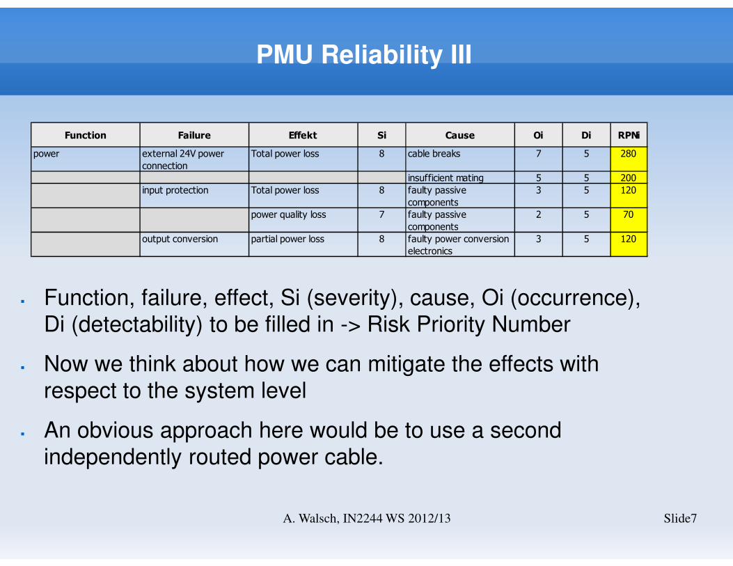
� Function, failure, effect, Si (severity), cause, Oi (occurrence), Di (detectability) to be filled in -> Risk Priority Number
� Now we think about how we can mitigate the effects with respect to the system level
� An obvious approach here would be to use a second independently routed power cable.
Function Failure Effekt Si Cause Oi Di RPNi
power external 24V power
connection
Total power loss 8 cable breaks 7 5 280
insufficient mating 5 5 200
input protection Total power loss 8 faulty passive
components
3 5 120
power quality loss 7 faulty passive
components
2 5 70
output conversion partial power loss 8 faulty power conversion
electronics
3 5 120
PMU Reliability IV
Slide8A. Walsch, IN2244 WS 2012/13
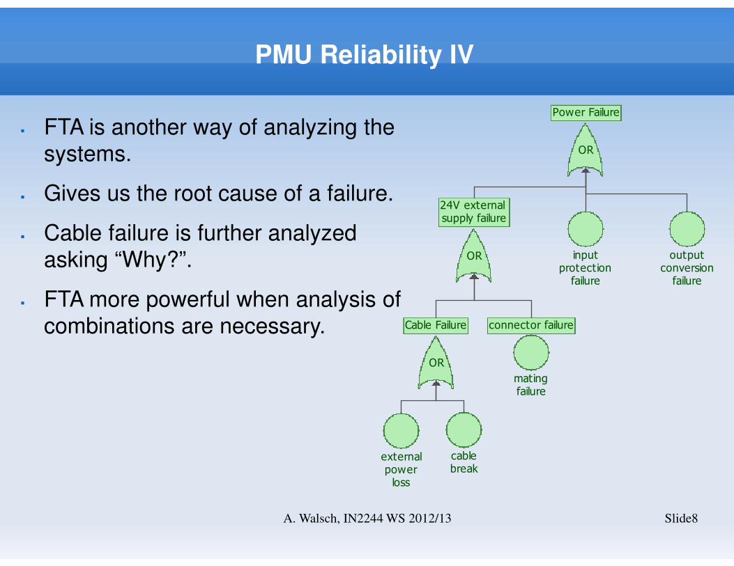
� FTA is another way of analyzing the systems.
� Gives us the root cause of a failure.
� Cable failure is further analyzed asking “Why?”.
� FTA more powerful when analysis of combinations are necessary.
OR
Power Failure
inputprotection
failure
outputconversion
failure
OR
24V external supply failure
matingfailure
connector failure
OR
Cable Failure
externalpowerloss
cablebreak
PMU Reliability VI
Slide9A. Walsch, IN2244 WS 2012/13
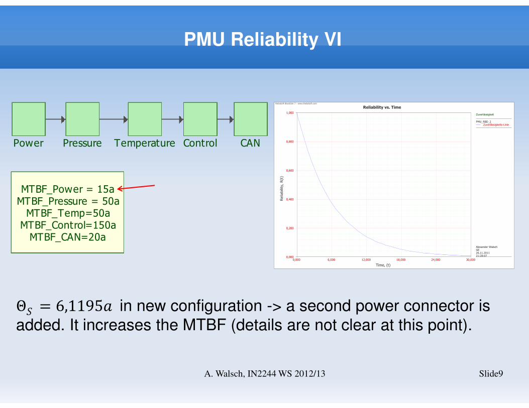
Θ�= 6,1195� in new configuration -> a second power connector is
added. It increases the MTBF (details are not clear at this point).
MTBF_Power = 15aMTBF_Pressure = 50aMTBF_Temp=50a
MTBF_Control=150aMTBF_CAN=20a
Pressure Temperature Control CANPower
ReliaSoft BlockSim 7 - www.ReliaSoft.com
Reliability vs. Time
Time, (t)
Relia
bility, R(t)
0,000 30,0006,000 12,000 18,000 24,0000,000
1,000
0,200
0,400
0,600
0,800
Zuverlässigkeit
PMU_RBD_2Zuverlässigkeits-Linie
Alexander WalschGE26.11.201121:28:07

Safety
Slide10A. Walsch, IN2244 WS 2012/13
� Safety is a system approach. The safety function and its safety integrity is critical on the super-system level (a process industry application in this case).
� Requirements on safety integrity are based on a risk analysis (last lecture).
� Safety integrity requirements can also be based on market analysis.
� For the PMU our marketing organization communicated:
� SIL3 in a 1oo2 configuration (duplex) – the competitor probably has some similar quality metric in the data sheet
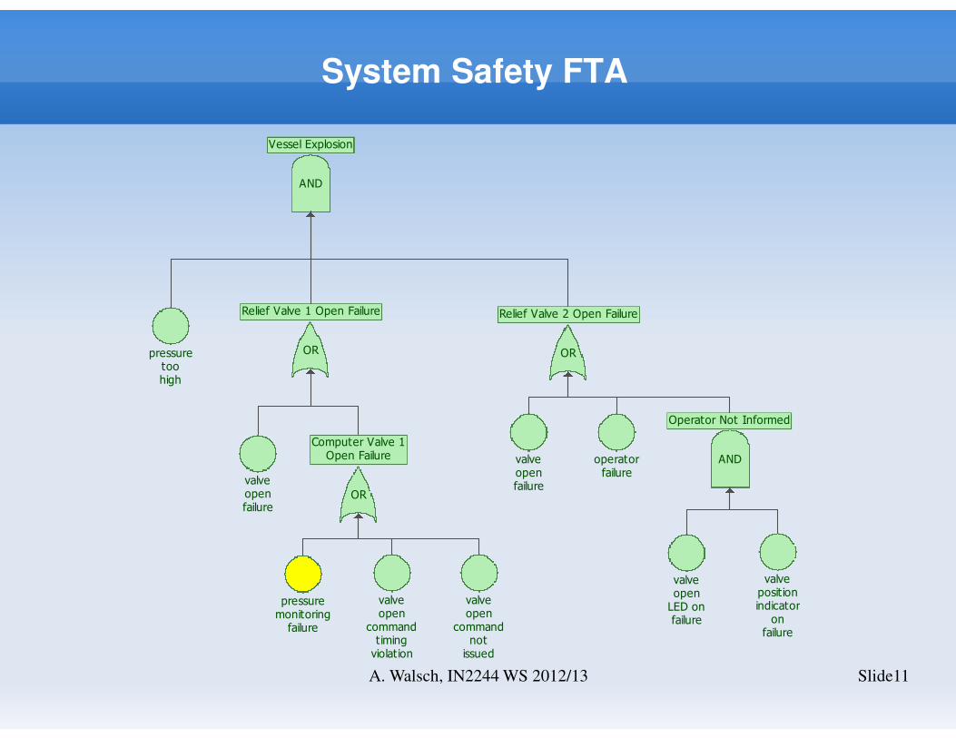
System Safety FTA
Slide11A. Walsch, IN2244 WS 2012/13
pressuretoohigh
valvepositionindicator
onfailure
AND
Operator Not Informed
valveopen
LED onfailure
operatorfailure
valveopenfailure
valveopen
commandtimingviolation
pressuremonitoring
failure
valveopen
commandnot
issued
valveopenfailure
OR
Computer Valve 1Open Failure
AND
Vessel Explosion
OR
Relief Valve 2 Open Failure
OR
Relief Valve 1 Open Failure

PMU Safety Function
Slide12A. Walsch, IN2244 WS 2012/13
� Wrong pressure readings can lead to hazardous states and possibly to harm at the super-system level.
� Imagine:
� Over pressure in vessels (chemical industry), oil and gas pipelines, or wells in oil and gas exploration
� Pressure readings must be correct (normal function) and faults at the PMU level (external or internal) need to be detected and communicated.
� Therefore, the safety function can simply be phrased like:“The PMU shall communicate a temperature compensated
pressure reading”.The message indicating a violation signals the “safe state”. This can be used in a fail-safe or a fail-operational approach.

Safety Function Integrity
� From marketing we know that the SIL of the PMU shall be 3 in a 1oo2 configuration.
� We need to understand now what effort that means in terms of developing the hardware and software for this system.
� Looking back a lecture we came across this:
� high and low demand of safety function and the failure table
� Architecture and SIL ratings
Source:
IEC61508

Safety Function Integrity II
Slide14A. Walsch, IN2244 WS 2012/13
� From marketing we know that the SIL of the PMU shall be 3 in a 1oo2 configuration. A system configuration might look like this:
Sensor Logic Element Final Element
PMU
PMU
S
S

Safety Function Integrity Modelling
Slide15A. Walsch, IN2244 WS 2012/13
� Both channels need to fail dangerously in order to enter a hazardous super-system state.
� Reliability of the safety function in a 1oo2 configuration:
R1oo2 = 2�������� − ��������� > Rsimplex; Rsimplex being the reliability
based on dangerous failures in a simplex configurationReliaSoft BlockSim 7 - www.ReliaSoft.com
Block-Zuverlässigkeit vs. Zeit
Zeit, (t)
Zuverlässigkeit, R(t)
0,000 600,000120,000 240,000 360,000 480,0000,000
1,000
0,200
0,400
0,600
0,800
Zuverlässigkeit
safety_function PMUSystemPMU
Alexander WalschGE28.11.201119:52:42
end
measurepressure
measurepressure
start

Requirements for Single Channel
Slide16A. Walsch, IN2244 WS 2012/13
� So far only random hardware failures (constant failure rate) have been considered.
� Systematic failures, especially software, have not been considered.
� Reliability of the safety function can be increased by adding redundancy (from SIL2 to SIL3).
� How can we include software errors into our model? We can not but we can visualize the big picture by adding common cause failures to the safety integrity assessment.
endcommoncause
measurepressure
measurepressure
start
SIL2
SIL2
SIL3
Requirements for Single Channel II
Slide17A. Walsch, IN2244 WS 2012/13
� A 1oo1D architecture for a single channel would meet the SIL2 requirement.
� uC + additional diagnostic circuit
� SIL3 for software is required.
� SFF = 90% - < 99%
� Process safety time: the deadline on reporting internal or external faults to prevent hazardous states (application specific)
PMU Availability
Slide18A. Walsch, IN2244 WS 2012/13
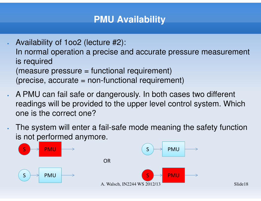
� Availability of 1oo2 (lecture #2): In normal operation a precise and accurate pressure measurement is required(measure pressure = functional requirement) (precise, accurate = non-functional requirement)
� A PMU can fail safe or dangerously. In both cases two different readings will be provided to the upper level control system. Which one is the correct one?
� The system will enter a fail-safe mode meaning the safety function is not performed anymore.
PMU
PMU
S
S PMUS
PMUS
OR
PMU Availability II
Slide19A. Walsch, IN2244 WS 2012/13
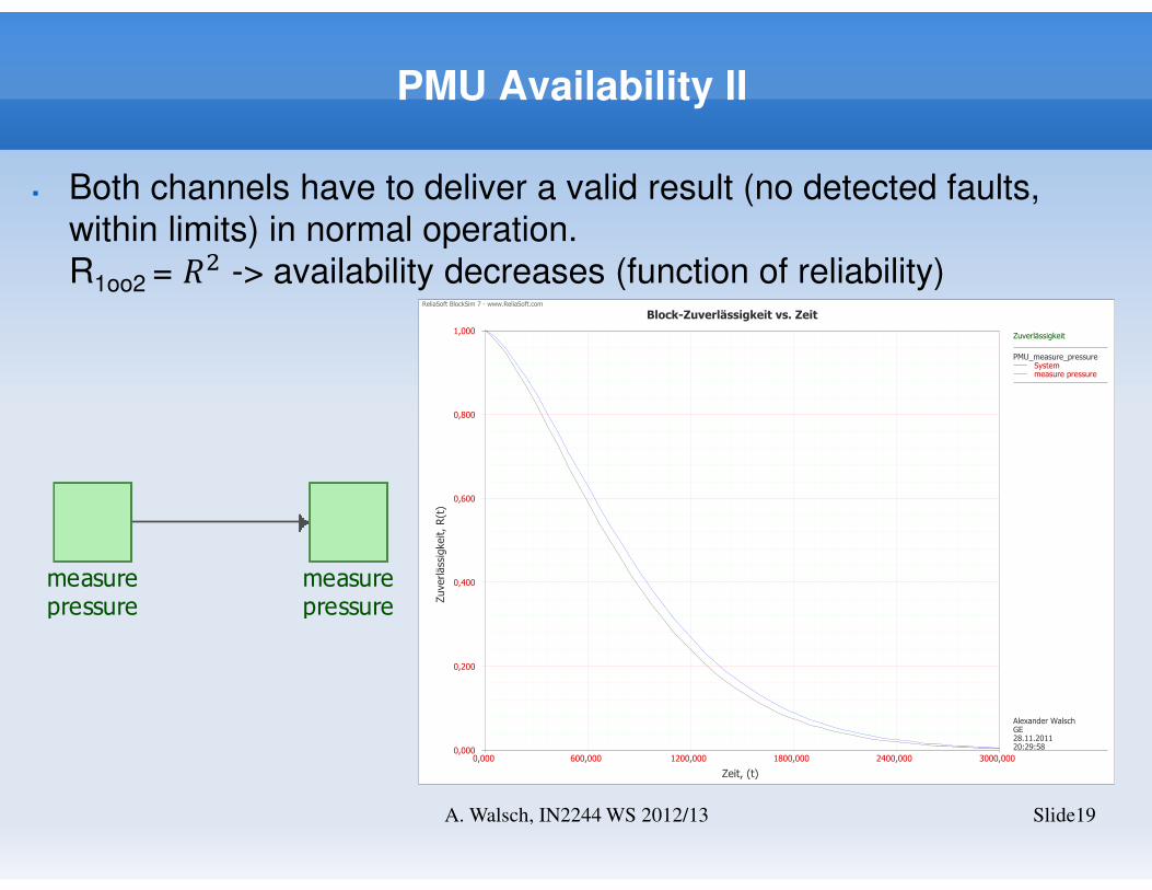
� Both channels have to deliver a valid result (no detected faults, within limits) in normal operation.R1oo2 = �� -> availability decreases (function of reliability)
measurepressure
measurepressure
ReliaSoft BlockSim 7 - www.ReliaSoft.com
Block-Zuverlässigkeit vs. Zeit
Zeit, (t)
Zuverlässigkeit, R(t)
0,000 3000,000600,000 1200,000 1800,000 2400,0000,000
1,000
0,200
0,400
0,600
0,800
Zuverlässigkeit
PMU_measure_pressureSystemmeasure pressure
Alexander WalschGE28.11.201120:29:58
PMU – Functional Requirements Analysis
Slide20A. Walsch, IN2244 WS 2012/13
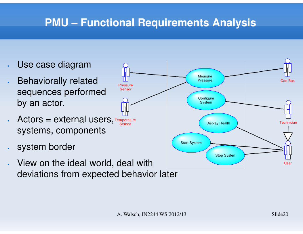
� Use case diagram
� Behaviorally relatedsequences performedby an actor.
� Actors = external users,systems, components
� system border
� View on the ideal world, deal withdeviations from expected behavior later
PressureSensor
TemperatureSensor
Can Bus
Technician
User
MeasurePressure
ConfigureSystem
Display Health
Start System
Stop Systen

PMU – Functional Requirements Analysis II
Slide21A. Walsch, IN2244 WS 2012/13
� Pre-conditions and post-conditions are the states of the system before and after successful execution of the use case. These can often be cross-referenced to the states in the system modes diagram.
� Non-functional requirements (see previous lecture)
� Alternate courses are a selection of alternative courses (fault conditions) and scenarios can be listed.
� Example screen layouts are illustrations of screens associated with the use case, including sample user data where available.
� Ties exceptions (faults, errors) and non-functional requirements to a use case
� Sequence diagrams can be added – however, they do not add new information at this stage.

PMU – Functional Requirements Analysis III
Slide22A. Walsch, IN2244 WS 2012/13
� Measure Pressure:
� Configure System:
Description
A request is received from the CAN bus. A temperature
compensated pressure reading is sent as response.
Pre-condition The system must be in 'Running' state.
Post-condition The system will be in 'Running' state.
Non-functional Requirements
Pressure is read with a maximum cycle time of 100ms,
output accuracy is 2%, precision is 0.5%.
Alternate Courses
Pressure outputs are in a range equivalent 0 - 16 bar. The
valid temperature ranges from -45°C to +85°C. If either range
is violated it must be signalled via CAN.
Description
A request for configuration is communicated to the system.
The requester is a technician which is equivalent to
someone with restricted access rights. During configuration
the system is not accepting CAN requests. The system
reports valid configuration.
Pre-condition The system must be in 'Active' state.
Post-condition The system will be in 'Active' state.
Non-functional Requirements
Access should be protected by a password. The
configuration data shall be stored in non-volatile memory.
Alternate Courses
All configuration options are checked for validity. If the
configuration data are not valid the system signals the 'Error'
state.

PMU – Functional Requirements Analysis IV
Slide23A. Walsch, IN2244 WS 2012/13
� Display Health:
� Start System:
Description
Power is applied and the system starts. The system
performs a self test. Upon successful completion the system
automatically enters the 'Running' state.
Pre-condition The system must be in 'Inactive' state
Post-condition The system will be in 'Active' state
Non-functional Requirements The system shall be in 'Running' state in less than 10s.
Alternate Courses
If the system detetcts a fault the 'Error' state shall be
entered. In this case the system shall report the error state
in less than 10s.
Description
Health of the system is requested by a user. The system
displays health using LEDs. Three LEDs are used. Green for
'Running', Red for 'Error', and yellow for all other system
states. The LEDs are visible from outside the system such
that the user gets visual feedback.
Pre-condition The system must be in 'Active' state.
Post-condition NA
Non-functional Requirements NA
Alternate Courses NA

PMU – Functional Requirements Analysis V
Slide24A. Walsch, IN2244 WS 2012/13
� Stop System:
� Summary:
� Identify the actors: external to the system
� Identify the use cases: “A behaviorally related sequence of interactions performed by an actor in a dialogue with the system to provide some measurable value to the actor”
� Create a use case diagram
� Write up use case descriptions
� The graphical notation does not add any information but makes talking to stakeholders sometimes easier
Description Power is removed.
Pre-condition The system must be in 'Active' state.
Post-condition The system will be in 'Inactive'state.
Non-functional Requirements NA
Alternate Courses NA

PMU – Functional Requirements Analysis VI
Slide25A. Walsch, IN2244 WS 2012/13
� System Usage Modeling Checklist
� Scale:A manageable number of use cases should be selected – 10 to 20
� GranularityUse cases should be not too high level (e.g. run system) or too low level (too many details)
� RelevanceUse cases should display normal actor-system interaction. Fault conditions should be part of more detailed analysis (e.g. in alternate courses)
� PartitioningUse cases describe end-to-end functionality and not generic functions of (to be developed sub-systems)
� ApplicabilityUse case diagrams describe the response to external stimuli. Therefore, they are suited to describe real-time systems on a high level.
PMU – Functional Requirements Analysis VII
Slide26A. Walsch, IN2244 WS 2012/13
� System Usage Diagram does not tell us:
� Internal Structure:What are the components of the systems that interact with the actors (mechanical, electrical, software), is there a component that controls activity?
� Interface Description:Interfaces are modeled as “classes”. A class name can already be used as a description (e.g. I2C bus)
� But the composite structure diagram does
� Also focuses on the system border, very high-level structural model
� Shows what is inside and outside our system

PMU – Scope
Slide27A. Walsch, IN2244 WS 2012/13
PMU
PMU control : Control
Backend : CAN
Configuration : RS232
Health : LED
Power : 24V PSU
Temperature : PT100 3Wire
Pressure : 4-20mA
PMU control : Control
Backend : CAN
Configuration : RS232
Health : LED
Power : 24V PSU
Temperature : PT100 3Wire
Pressure : 4-20mA
Can BusPressureSensor
TemperatureSensor
Technician
User
Power Supply

PMU – Scope II
Slide28A. Walsch, IN2244 WS 2012/13
� Content of Requirements Specification
� Context structure diagram as in previous slide: shows what is inside and outside the systems responsibility, nature of interfaces:
� Pressure sensor: 4 – 20 mA, screw terminal, sensor powered externally or by PMU
� Temperature sensor: PT100 three wire, screw terminal
� Power: screw terminal
� CAN: D-sub 9
� Health: LEDs
� Config: RS232 – D-sub 9 (PC interface)
� Interface description can be added to context structure but can also be added as text in the specification

PMU – System States
Slide29A. Walsch, IN2244 WS 2012/13
Inactive
Configuration
Init Running
Error
Active
Init Running
Error
/
[s elf tes t finished]/m easure pres sure
[ fa u lt ] /
[ fa u lt ] /
«C rea te» / «D es troy » /
[power on]/s tart sy s tem [power off] /s top sy s tem
[c onfiguration reques t]/configure sy s tem
[c onfigurat ion valid]/

PMU – System States II
Slide30A. Walsch, IN2244 WS 2012/13
� System states: states of the system when viewed as a black box
� States of the PMU control object
� States allow or disallow certain use cases
� State transitions often triggered by actor interaction (see scope in previous slides)
� Where use cases are shown as actions, it is important to recognize that the action implied is the initiation of the use case, not necessarily its completion.

PMU Requirements Specification
Slide31A. Walsch, IN2244 WS 2012/13