double ferrule fittings - fluid controls fluid controls... · 1 introduction fluid controls double...
TRANSCRIPT

FLUID CONTROLS PRIVATE LIMITED
DOUBLE FERRULE FITTINGS

1
INTRODUCTION
Fluid Controls Double Ferrule Compression Tube Fittings Have The Following Features
DESIGN
PERFORMANCE
ASSEMBLY
SERVICE
Fluid Controls Double Ferrule Compression Tube Fittings provide leak proof torque free seals at all tubing connections. They eliminate hazardous leaks in instrumentation, process, pneumatic, hydraulic, gas and other applicable tubing system which could otherwise turn out to be costly to the installation.
The basic Fluid Controls Double Ferrule Tube Fittings is a four piece Fitting consisting of the Nut, the
Back Ferrule, the Front Ferrule and the Body. When installed, it becomes a five piece connection with the
addition of the tubing providing a solid leak free joint.
The two ferrules grasp tightly around the tube with no damage to the tube wall. Exhaustive tests have
proven that the tubing will yield before a Fluid Control Double Ferrule joint starts leaking.
The secret behind the success of the Fluid Controls Double Ferrule Fitting lies in the two ferrule
design which is a combination of geometry and metallurgy. All the action in the fitting is by an axial
movement along the tube instead of a rotary motion to create the joint. This axial movement prevents any
torque to be transmitted from a fitting to the tubing. Since there is no initial strain in the tubing, the making of
the joint does not weaken the tubing.
Another advantage of the Fluid Controls Double Ferrule Fitting is that the sequential action of the twin
ferrule overcomes variations in the wall thickness, hardness and dimensional tolerance of the tubes. This
way proper ferrule interaction compensates for most of the variables which lead to failure in other fittings.
Fluid Controls Double Ferrule Fittings are easy to install and require no special tools in the process.
They are reusable several times and can withstand heavy impulse and vibration both in vacuum and
pressure systems. Absence of damage to the tube surface prevents fatigue failure.
We give below a summary of the advantages of Fluid Controls Double Ferrule Fitting.
nBe self aligning
nWorks on thick and thin wall tubing
nResists vibration
nWorks on a variety of tube materials
nHave all components made of the same material and hence possess thermal compatibility and
corrosion resistance.
nResistance to temperature cycling
nCompensates for the variables encountered in tube materials.
nDimensions and metallurgy.
nDoes not significantly reduce flow area
nWorks on vacuum as well as low and high pressures
nSeals at low cryogenic temperatures as well as elevated temperatures rated for the tube
nSeals consistently over a wide range of temperature cycling
nSeals repeatedly under make and break conditions
nResistant to pressure upto the burst point with the tubing without leakage.
nUses geometry rather than torque for uniformity of make-up. It requires only one and quarter turns
after snug tight to complete the joint.
nDoes not require dis-assembly and inspection of ferrule swaging at every make-up.
nDoes not require any special tools for assembly.
Fluid Controls Double Ferrule Tube Fittings are available in a wide range of materials, sizes, connections and
configurations from our local distributors with substantial back up stocks to support our dealers
inventories.
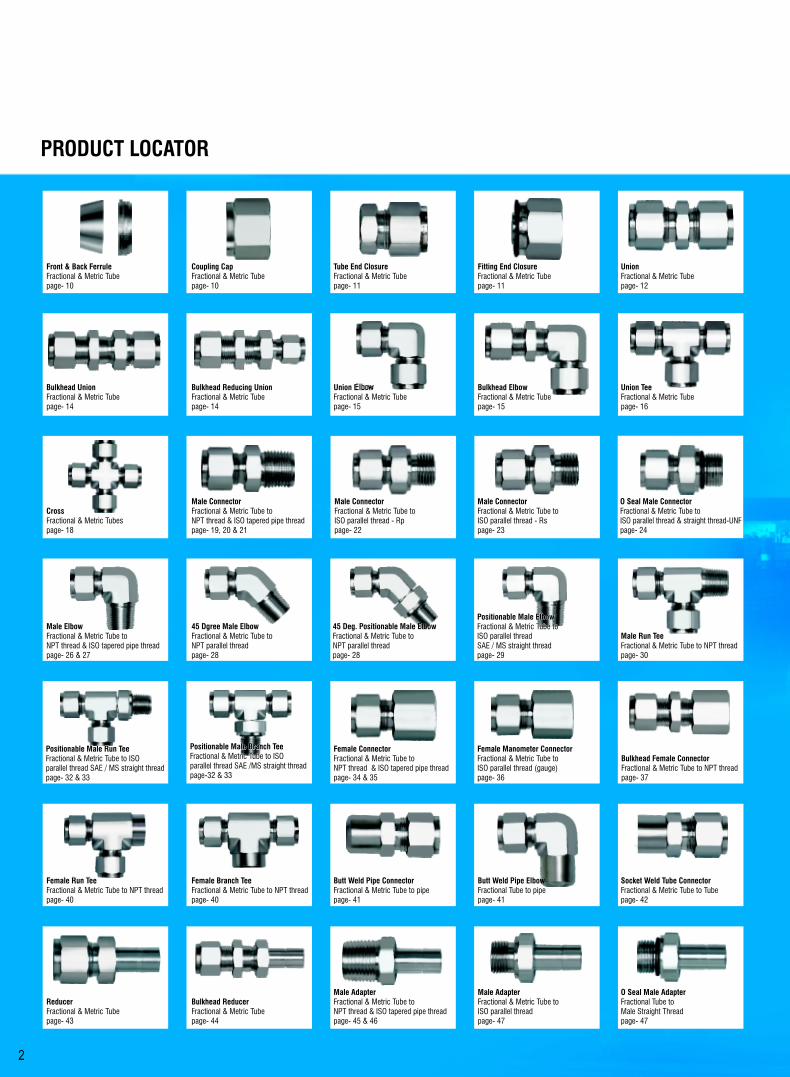
PRODUCT LOCATOR
2
ReducerFractional & Metric Tubepage- 43
Male AdapterFractional & Metric Tube toNPT thread & ISO tapered pipe threadpage- 45 & 46
Bulkhead ReducerFractional & Metric Tubepage- 44
Male AdapterFractional & Metric Tube toISO parallel threadpage- 47
O Seal Male AdapterFractional Tube toMale Straight Threadpage- 47
Socket Weld Tube ConnectorFractional & Metric Tube to Tubepage- 42
Butt Weld Pipe ConnectorFractional & Metric Tube to pipepage- 41
Female Branch TeeFractional & Metric Tube to NPT threadpage- 40
Female Run TeeFractional & Metric Tube to NPT threadpage- 40
Female Manometer ConnectorFractional & Metric Tube toISO parallel thread (gauge)page- 36
Bulkhead Female ConnectorFractional & Metric Tube to NPT thread page- 37
Female ConnectorFractional & Metric Tube toNPT thread & ISO tapered pipe threadpage- 34 & 35
Coupling CapFractional & Metric Tubepage- 10
Tube End ClosureFractional & Metric Tubepage- 11
Fitting End ClosureFractional & Metric Tubepage- 11
UnionFractional & Metric Tubepage- 12
Front & Back FerruleFractional & Metric Tubepage- 10
Bulkhead UnionFractional & Metric Tubepage- 14
Bulkhead Reducing UnionFractional & Metric Tubepage- 14
Union ElbowFractional & Metric Tubepage- 15
Union Tee Fractional & Metric Tubepage- 16
Male ConnectorFractional & Metric Tube toNPT thread & ISO tapered pipe threadpage- 19, 20 & 21
CrossFractional & Metric Tubespage- 18
Male ConnectorFractional & Metric Tube toISO parallel thread - Rppage- 22
Male ConnectorFractional & Metric Tube toISO parallel thread - Rspage- 23
Notes
Double Ferrule Fittings
51
O Seal Male ConnectorFractional & Metric Tube toISO parallel thread & straight thread-UNFpage- 24
Bulkhead ElbowFractional & Metric Tubepage- 15
Butt Weld Pipe ElbowFractional Tube to pipepage- 41
Positionable Male Branch TeeFractional & Metric Tube to ISO parallel thread SAE /MS straight threadpage-32 & 33
Positionable Male Branch TeeFractional & Metric Tube to ISO parallel thread SAE /MS straight threadpage-32 & 33
Positionable Male Branch TeeFractional & Metric Tube to ISO parallel thread SAE /MS straight threadpage-32 & 33
Positionable Male Run TeeFractional & Metric Tube to ISO parallel thread SAE / MS straight threadpage- 32 & 33
Positionable Male Run TeeFractional & Metric Tube to ISO parallel thread SAE / MS straight threadpage- 32 & 33
Positionable Male Run TeeFractional & Metric Tube to ISO parallel thread SAE / MS straight threadpage- 32 & 33
Positionable Male ElbowFractional & Metric Tube toISO parallel threadSAE / MS straight threadpage- 29
Positionable Male ElbowFractional & Metric Tube toISO parallel threadSAE / MS straight threadpage- 29
Male Run TeeFractional & Metric Tube to NPT thread page- 30
Positionable Male ElbowFractional & Metric Tube toISO parallel threadSAE / MS straight threadpage- 29
Male ElbowFractional & Metric Tube toNPT thread & ISO tapered pipe threadpage- 26 & 27
45 Dgree Male ElbowFractional & Metric Tube toNPT parallel threadpage- 28
45 Deg. Positionable Male ElbowFractional & Metric Tube toNPT parallel threadpage- 28
45 Deg. Positionable Male ElbowFractional & Metric Tube toNPT parallel threadpage- 28

3
Female Manometer AdapterFractional & Metric Tube toISO parallel thread (gauge)page- 49
Female AdapterFractional & Metric Tube toNPT thread & ISO tapered pipe threadpage- 48 & 49
Socket Weld Tube ElbowFractional & Metric Tube to tubepage- 42
Female ElbowFractional & Metric Tube to NPT threadpage- 38 & 39
Male Branch TeeFractional & Metric Tube to NPT thread page- 31
Reducing UnionFractional & Metric Tubepage- 13
Reducing Union Tee Fractional & Metric Tubepage- 17
Notes
Double Ferrule Fittings
50
Bulk Head Male ConnectorFractional & Metric Tube to NPT thread page- 25

TUBING SELECTION
TUBING HARDNESS
TUBING WALL THICKNESS
Proper selection , handling, installation of tubing when combined with the proportion of the Fluid Controls
Double Ferrule Tube fittings are essential to reliable tubing systems. Although, Fluid Controls Pvt. Ltd. is not a
tubing manufacturer or supplier, we feel it is our duty to impress on our customers the vital importance of
careful selection of high quality tubing in order to install safe and leak free systems. Fluid Controls will be happy
to assist in the selection of such tubes to our customers when requested.
Selection of tubes are based on the material, hardness, wall thickness and surface finish. The ASTM
specifications for various tubes cover material, hardness and wall thickness. They do not give details on
the surface finish.
For example, ASTM A 269, one of the most widely used specifications reads as follows in clause 14.1
under the title “FINISH”.
“ Finished tubes shall be reasonably straight and have smooth ends free from burrs. They shall be free from
injurious defects and shall have a workman like finish. Minor defects may be removed by grinding provided
the wall thickness is not decreased to less than that permitted in clause 13”.
The ASTM is silent on the surface finish which is required to be smooth and free from any scratches, axial
or circumferential which will allow leakage paths along the joints.
We give our comments below on the selections of tubes. These requirements are specified under section
3.1.9 of ASTM A 269 or section 3.1.11 of ASTM A 213
Tubing must always be softer than the fitting material by using the suggested hardness of the tubes as
explained in tubing specification you will ensure joints which work perfectly.
The most misunderstanding about tubing hardness are in the area of stainless steel tubing. Fluid Controls
Double Ferrule Tube Fittings made from stainless steel have been tested successfully with tubing hardness
upto RB 90, the maximum hardness allowable under ASTM A 213 and A 269. Although such tubing
hardness is permissible and Fluid Controls Double Ferrule Fittings will perform satisfactorily on such
tubing, they will not give the maximum advantage and performance for tubes of hardness above RB 80.
Hence, it is suggested that when purchasing stainless steel tubes to ASTM A 213 / A 269, you specify that
the hardness of the tubes should not exceed RB 80. Better still we have found that the best results are
obtained where the stainless steel tubing hardness is in the range RB 70-74. Such tubing ( RB 70-74)
lowers installed costs because it is more easily bent and installed.
Tubing installers should be particularly careful that the full suggested one and quarter turns after snug tight
be performed to ensure the proper joints. This will give the best performance This is especially so in the
case of harder tubing where higher torques are required.
We again repeat that the RB 80 maximum hardness is a suggestion and not a restriction against the use of
Fluid Controls Double Ferrule Fitting in stainless steel to increase the performance of the fitting. However, if
the tubing hardness exceeds RB 90, special fittings needs to be ordered.
The allowable pressure rating of tubings for the wide range of wall thickness are calculated from “S”values
as specified by ANSI Code B 31.1. The range of tubing wall thicknesses vary from 0.028 “ to 0.109 “ in the
inch OD series and 0.75 mm to 2.5 mm in the Metric OD series respectively. These wall thicknesses are
generally preferred for tube sizes upto 1” OD and 25mm OD in the two systems respectively. For higher
tube sizes, these wall thicknesses may be increased to 0.125 or ( 3mm) and 0.167 “ or( 4mm )in the inch
(metric) system respectively.
Tubings with higher wall thickness are generally not recommended as they may lead to lowering of
performance and higher torque requirements to create the joint. Tubings with lower wall thicknesses are
also not recommended as there is a possibility of collapse of the tube.
Fluid Controls will be very happy to provide their customers with working pressure ratings as per ANSI
Code B31.1 for various wall thicknesses in the above mentioned ranges for inch and metric size tubings.
4
Double Ferrule Fittings
49
FEMALE ADAPTERMETRIC OD Tubes X Female NPT Threads
T P FluidTube NPT A B E F ControlsOD Female min. A/F Part No.
3 1/4 31.7 15.0 2.4 14 SAF 3-4N
6 1/8 32.5 9.9 4.6 14 SAF 6-2N
6 1/4 37.1 15.0 4.6 19 SAF 6-4N
8 1/4 37.6 15.0 6.4 19 SAF 8-4N
10 1/4 38.1 15.0 7.7 19 SAF 10-4N
10 3/8 40.1 15.0 7.7 22 SAF 10-6N
10 1/2 46.5 19.8 7.7 27 SAF 10-8N
12 1/4 43.7 15.0 9.1 19 SAF 12-4N
12 1/2 52.3 19.8 9.1 27 SAF 12-8N
16 1/2 47.7 19.8 9.1 27 SAF 16-8N
22 3/4 52.0 20.6 15.0 35 SAF 22-12N
25 3/4 51.2 20.6 15.0 35 SAF 25-12N
25 1 66.5 25.4 19.8 41 SAF 25-16N
32 1.1/4 78.0 25.4 27.4 55 SAF 32-20N
38 1.1/2 88.9 27.6 33.3 60 SAF 38-24N
METRIC OD Tubes X Female ISO* Tapered Pipe Threads
T P FluidTube ISO A B E F ControlsOD Female min. A/F Part No.
6 1/8 32.5 9.9 4.6 14 SAF 6-2Rx
6 1/4 37.1 15.0 4.6 19 SAF 6-4Rx
8 1/4 37.6 15.0 6.4 19 SAF 8-4Rx
10 1/4 38.1 15.0 7.7 19 SAF 10-4Rx
10 3/8 40.1 15.0 7.7 22 SAF 10-6Rx
12 1/4 43.7 15.0 9.1 19 SAF 12-4Rx
12 1/2 52.3 19.8 9.1 27 SAF 12-8Rx
16 1/2 47.7 19.8 9.1 27 SAF 16-8Rx
22 3/4 52.0 20.6 15.0 35 SAF 22-12Rx
25 3/4 51.2 20.6 15.0 35 SAF 25-12Rx
25 1 66.5 25.4 19.8 41 SAF 25-16Rx
32 1.1/4 78.0 25.4 27.4 55 SAF 32-20Rx38 1.1/2 88.9 27.6 33.3 60 SAF 38-24Rx
* Reference Specifications : BS 21: ISO 7/1 : JIS B 0203 : DIN 2999 : IS 554
FEMALE MANOMETER ADAPTERINCH OD Ports X Female ISO* Parallel Threads (gage)
T P F FluidTube ISO A B E A/F a2 d4 b t2 ControlsOd Female min. min. Part No.
1/4 1/4 35.3 13.0 4.8 19 1.6 5.8 9.4 17.0 4 SAF-MAN
3/8 3/8 39.4 14.2 6.6 24 1.6 - 9.9 - 6 SAF-MAN
1/2 1/2 45.7 18.8 7.1 27 1.6 - 14.5 - 8 SAF-MAN
METRIC OD Ports X Female ISO* Parallel Threads (gage)
T P F FluidTube ISO A B E A/F a2 d4 b t2 ControlsOd Female min. min. Part No.
6 1/4 35.3 12.9 4.6 19 1.6 5.5 9.5 17.0 SAF 6-4MAN
6 3/8 38.4 14.1 4.6 24 1.6 6.5 10.0 20.3 SAF 6MAN
6 1/2 42.9 18.9 4.6 27 1.6 7.0 14.5 24.9 SAF 6-8MAN
8 1/4 33.0 12.9 5.5 19 1.6 - 9.5 - SAF 8-4MAN
8 1/2 43.7 18.9 6.2 27 1.6 7.0 14.5 24.9 SAF 8MAN
10 1/4 34.5 12.9 5.5 19 1.6 - 9.5 - SAF 10-4MAN
10 1/2 40.1 18.9 7.0 27 1.6 - 14.5 - SAF 10-8MAN
12 1/4 40.1 12.9 5.5 19 1.6 - 9.5 - SAF 12-4MAN
12 1/2 48.8 18.9 7.0 27 1.6 - 14.5 - SAF 12-8MAN
No seal is made around the male thread. Instead, a gasket is dropped into the flat bottom in the female thread, and the end of the male threaded end exerts a load on the gasket to seal.
* Reference Specifications : BS 2779 : ISO 228/1 : JIS B0202 : DIN-ISO 228/1
Double Ferrule Fittings

Double Ferrule Fittings
TUBING FOR GAS SERVICE
TUBING HANDLING
For the greatest safety factor against surface defects in any gas system it is recommended that the wall
thickness employed be not less than that shown in the table below;
Suggested Suggested
Tube Minimum Tube Minimum O.D Wall Thickness O.D Wall Thickness
1/16” .028” 3/4” .062”
1/8” .028” 7/8”(20mm) .073”
1/4”(6mm) .028” 1”(25mm) .083”
5/16”(8mm) .035” 1-1/4” .104”
3/8”(10mm) .035” 1-1/2” .125”
1/2”(12mm) .041” 2” .167”
5/8”(16mm) .052”
Light gases such as helium, hydrogen, nitrogen, etc have very small molecules which can escape through
even the minutest leak path created by surface defect on the tubing. As the tube OD increases, so does the
likelihood of a scratch or other surface defect interfering with proper sealing.
The most successful connection for gas service will occur if all the installation instructions are carefully
followed and the heavier permissible wall thickness of tubing are selected. A heavy wall thickness resist
ferrule action more than a thin wall thickness allowing the ferrules to coin out minor surface in perfection. A
thin wall tube will collapse offering little resistance to ferrule action during preparation of joints. This
reduces the chances of coining out surface defects essential for gas service.
Scratches on tube OD are a potential source of problems in leak-tight tubing systems. Good handling
practices can greatly reduce scratches and protect the good surface finish of well made tubes.
Tubing should never be dragged out of a tubing rack. Particularly in sizes ¾” and larger, the weight of the
length being pulled out is sufficient to gouge the OD if there are any burrs on the end of the tubes below it in
the rack.
Tubing should never be dragged across cement, asphalt, gravel or any other surface which could scratch
the surface and recreate the leakage parts.
Tube cutters or hacksaws should always be sharp, and you should not try to take too deep a cut with each
turn of the cutter or with each back and forth motion of the saw blade.
Tube ends should always be debarred. This allows more easy entrance of the tube into the fitting bore and
helps to assure the installer that the tubing will go all the way through the ferrules without damage to the
ferrule sealing edge.
48 5
NOTE: The combinations shown above are representative of various possibilities. Other combinations not shown are also available. Please consult us.
Double Ferrule Fittings
FEMALE ADAPTERINCH OD Tubes X Female NPT Threads
T P FluidTube NPT A B E F ControlsOD Female min. A/F Part No.
1/8 1/8 31.5 10.4 2.4 14 2 SAF -N
1/8 1/4 35.3 15.0 2.4 19 2-4 SAF -N
1/4 1/8 33.0 10.4 4.8 14 4-2 SAF -N
1/4 1/4 37.0 15.0 4.8 19 4 SAF -N
1/4 3/8 39.4 15.0 4.8 22 4-6 SAF -N
1/4 1/2 45.5 19.8 4.8 27 4-8 SAF -N
5/16 1/4 37.6 15.0 6.3 19 5-4 SAF -N
3/8 1/4 38.1 15.0 7.1 19 6-4 SAF -N
3/8 3/8 40.4 15.0 7.1 22 6 SAF -N
3/8 1/2 46.7 19.8 7.1 27 6-8 SAF -N
1/2 1/4 43.5 15.0 9.9 19 8-4 SAF -N
1/2 3/8 45.5 15.0 9.9 22 8-6 SAF -N
1/2 1/2 51.8 19.8 9.9 27 8 SAF -N
5/8 1/2 53.0 19.8 12.7 27 10-8 SAF -N
3/4 1/2 52.8 19.8 15.0 27 12-8 SAF -N
3/4 3/4 52.8 20.6 15.0 35 12 SAF -N
3/4 1 58.4 25.4 15.0 41 12-16 SAF -N
1 3/4 60.7 20.6 20.3 35 16 SAF -N
1 1 64.3 25.4 20.3 41 16-12 SAF -N
1.1/4 1.1/4 77.7 25.4 27.6 55 20 SAF -N
1.1/2 1.1/2 88.9 27.6 33.2 60 24 SAF -N
INCH OD Tubes X Female ISO* Tapered Pipe Threads
T P FluidTube ISO A B E F ControlsOD Female min. A/F Part No.
1/4 1/4 37.0 15.0 4.8 19 4 SAF -Rx
1/4 3/8 39.4 15.0 4.8 22 4-6 SAF -Rx
1/4 1/2 45.5 19.8 4.8 27 4-8 SAF -Rx
3/8 1/4 38.1 15.0 7.1 19 6-4 SAF -Rx
3/8 3/8 40.4 15.0 7.1 22 6 SAF -Rx
1/2 1/4 43.5 15.0 9.9 19 8-4 SAF -Rx
1/2 3/8 45.5 15.0 9.9 22 8-6 SAF -Rx
1/2 1/2 51.8 19.8 9.9 27 8 SAF -Rx
3/4 3/4 52.8 20.6 15.0 35 12 SAF -Rx
3/4 1 58.4 25.4 15.0 41 12-16 SAF -Rx
1 3/4 60.7 20.6 20.3 35 16 SAF -Rx
1 1 64.3 25.4 20.3 41 16-12 SAF -Rx
1.1/4 1.1/4 77.7 25.4 27.6 55 20 SAF -Rx
1.1/2 1.1/2 88.9 27.6 33.2 60 24 SAF -Rx
* Reference Specifications : BS 21: ISO 7/1 : JIS B 0203 : DIN 2999 : IS 554
NOTE: Female adaptors are also availablewith ISO parallel Female Pipe Threads, Their dimensions are same as for similar combination of tube and ISO Taper Pipe Threads. Please consult us.
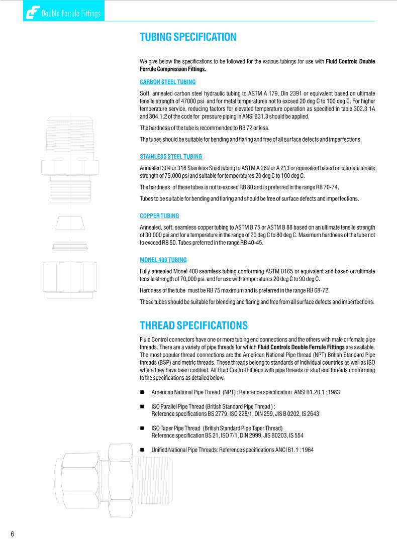
TUBING SPECIFICATION
CARBON STEEL TUBING
STAINLESS STEEL TUBING
COPPER TUBING
MONEL 400 TUBING
THREAD SPECIFICATIONS
We give below the specifications to be followed for the various tubings for use with Fluid Controls Double
Ferrule Compression Fittings.
Soft, annealed carbon steel hydraulic tubing to ASTM A 179, Din 2391 or equivalent based on ultimate
tensile strength of 47000 psi and for metal temperatures not to exceed 20 deg C to 100 deg C. For higher
temperature service, reducing factors for elevated temperature operation as specified in table 302.3 1A
and 304.1.2 of the code for pressure piping in ANSI B31.3 should be applied.
The hardness of the tube is recommended to RB 72 or less.
The tubes should be suitable for bending and flaring and free of all surface defects and imperfections.
Annealed 304 or 316 Stainless Steel tubing to ASTM A 269 or A 213 or equivalent based on ultimate tensile
strength of 75,000 psi and suitable for temperatures 20 deg C to 100 deg C.
The hardness of these tubes is not to exceed RB 80 and is preferred in the range RB 70-74.
Tubes to be suitable for bending and flaring and should be free of surface defects and imperfections.
Annealed, soft, seamless copper tubing to ASTM B 75 or ASTM B 88 based on an ultimate tensile strength
of 30,000 psi and for a temperature in the range of 20 deg C to 80 deg C. Maximum hardness of the tube not
to exceed RB 50. Tubes preferred in the range RB 40-45.
Fully annealed Monel 400 seamless tubing conforming ASTM B165 or equivalent and based on ultimate
tensile strength of 70,000 psi. and for use with temperatures 20 deg C to 90 deg C.
Hardness of the tube must be RB 75 maximum and is preferred in the range RB 68-72.
These tubes should be suitable for blending and flaring and free from all surface defects and imperfections.
Fluid Control connectors have one or more tubing end connections and the others with male or female pipe
threads. There are a variety of pipe threads for which Fluid Controls Double Ferrule Fittings are available.
The most popular thread connections are the American National Pipe thread (NPT) British Standard Pipe
threads (BSP) and metric threads. These threads belong to standards of individual countries as well as ISO
where they have been codified. All Fluid Control Fittings with pipe threads or stud end threads conforming
to the specifications as detailed below.
nAmerican National Pipe Thread (NPT) : Reference specification ANSI B1.20.1 : 1983
nISO Parallel Pipe Thread (British Standard Pipe Thread ) :Reference specifications BS 2779, ISO 228/1, DIN 259, JIS B 0202, IS 2643
nISO Taper Pipe Thread (British Standard Pipe Taper Thread)Reference specification BS 21, ISO 7/1, DIN 2999, JIS B0203, IS 554
nUnified National Pipe Threads: Reference specifications ANCI B1.1 : 1964
6
Double Ferrule Fittings
MALE ADAPTERINCH OD Tubes x Male ISO* Parallel Threads - RS
T P FluidTube ISO A B E F Fd ControlsOD Male min. A/F Part No.
1/8 1/8 31.0 7.1 2.4 14 13.7 2 SAM-Rs
1/8 1/4 35.8 11.2 2.4 19 17.8 2-4 SAM-Rs
1/4 1/8 33.3 7.1 4.0 14 13.7 4-2 SAM-Rs
1/4 1/4 38.1 11.2 4.8 19 17.8 4 SAM-Rs
3/8 1/4 39.9 11.2 5.8 19 17.8 6-4 SAM-Rs
3/8 3/8 40.6 11.2 7.1 22 21.6 6 SAM-Rs
1/2 1/4 45.5 11.2 5.8 19 17.8 8-4 SAM-Rs
1/2 3/8 46.3 11.2 7.9 22 21.6 8-6 SAM-Rs
1/2 1/2 49.3 14.2 9.9 27 26.0 8 SAM-Rs
3/4 3/4 54.9 15.7 15.0 32 31.8 12 SAM-Rs
1 1 64.5 18.2 19.8 41 38.8 16-12 SAM-Rs
1.1/4 1.1/4 79.5 19.8 27.4 50 49.0 20 SAM-Rs
1.1/2 1.1/2 93.7 22.1 33.3 55 54.7 24 SAM-Rs
METRIC OD Tubes x Male ISO* Parallel Threads - RS
T P FluidTube ISO A B E F Fd ControlsOD Male min. A/F Part No.
3 1/8 31.0 7.1 2.4 14 13.7 SAM 3-2Rs
3 1/4 35.8 11.2 22.0 19 17.8 SAM 3-4Rs
6 1/8 34.3 7.1 4.0 14 13.7 SAM 6-2Rs
6 1/4 39.1 11.2 4.6 19 17.8 SAM 6-4Rs
8 1/4 40.1 11.2 5.8 19 17.8 SAM 8-4Rs
10 1/4 40.9 11.2 5.8 19 17.8 SAM 10-4Rs
10 3/8 41.7 11.2 7.7 22 21.7 SAM 10-6Rs
10 1/2 44.7 14.2 7.7 27 25.9 SAM 10-8Rs
12 1/4 46.7 11.2 5.8 19 17.8 SAM 12-4Rs
12 3/8 47.2 11.2 7.9 22 21.7 SAM 12-6Rs
12 1/2 50.5 14.2 9.1 27 25.9 SAM 12-8Rs
16 1/2 50.5 14.2 12.7 27 25.9 SAM 16-8Rs
22 3/4 55.2 15.7 15.8 35 32.0 SAM 22-12Rs
22 1 64.5 18.3 19.8 41 39.0 SAM 22-16Rs
25 1.1/4 79.5 19.8 27.4 50 49.0 SAM 25-20Rs
25 1.1/2 93.7 22.1 33.3 55 54.7 SAM 25-24Rs
* Reference Specifications : BS 2779 : ISO 228/1 : JIS B0202 : DIN-ISO 228/1
O SEAL MALE ADAPTER INCH OD Tubes x Male Straight Threads - UNF
T S FluidTube UNF A B E F Fd O Ring ControlsOD Male min. A/F Part No. Part No.
1/8 5/16 - 24 32.5 8.6 2.4 14 13.8 1 OPU 2 SAO-U
1/4 7/16 - 24 39.2 10.4 4.8 19 18.8 2 OPU 4 SAO-U
5/16 1/2 - 24 41.7 11.2 6.3 22 21.8 3 OPU 5 SAO-U
5/16 9/16 - 24 43.2 12.0 7.1 24 23.6 4 OPU 6 SAO-U
1/2 3/4 - 24 49.5 12.0 9.9 27 26.8 6 OPU 8 SAO-U
3/4 11/16 - 12 55.0 14.3 15.0 38 37.8 12 OPU 12 SAO-U
1 15/16 - 12 62.5 14.3 19.8 45 44.0 16 OPU 16 SAO-U
1.1/4 15/8 - 12 79.5 18.3 27.4 55 54.0 20 OPU 20 SAO-U
1.1/2 17/8 - 12 92.2 19.8 33.3 60 58.0 24 OPU 24 SAO-U
Double Ferrule Fittings
47
NOTE : 1. For use with soft metal gasket (usually copper) between fitting and female par t face2. Also available in ISO Parallel Threads - RP series for beaded metal gaskets. See page 22/23 for explanation.

7
Double Ferrule Fittings
MALE ADAPTERMETRIC OD Tubes x Male NPT Threads
T P FluidTube NPT A B E F ControlsOD Male min. A/F Part No.
3 1/4 34.8 9.6 7.1 14 SAM 3-2N
6 1/8 32.8 14.3 4.6 14 SAM 6-2N
6 1/4 38.1 14.3 4.6 14 SAM 6-4N
8 1/4 39.1 14.3 6.2 14 SAM 8-4N
10 1/4 39.9 14.3 7.7 14 SAM 10-4N
10 3/8 40.6 14.3 7.7 19 SAM 10-6N
12 1/4 46.5 14.3 7.1 14 SAM 12-4N
12 3/8 46.5 14.3 9.1 19 SAM 12-6N
12 1/2 52.0 14.3 9.1 22 SAM 12-8N
25 3/4 62.0 19.1 15.7 27 SAM 25-12N
25 1 66.8 23.8 15.7 35 SAM 25-16N
30 1 79.2 23.8 22.2 41 SAM 30-16N
30 1.1/4 80.0 23.8 24.6 45 SAM 30-20N
32 1.1/4 81.0 23.8 27.4 46 SAM32-20N
38 1.1/2 92.2 26.2 33.3 55 SAM 38-24N
METRIC OD Tubes x Male ISO* Tapered Pipe Threads
T P FluidTube ISO A B E F ControlsOD Male min. A/F Part No.
3 1/4 34.8 9.6 7.1 14 SAM 3-2Rx
6 1/8 32.8 14.3 4.6 14 SAM 6-2Rx
6 1/4 38.1 14.3 4.6 14 SAM 6-4Rx
8 1/4 39.1 14.3 6.2 14 SAM 8-4Rx
10 1/4 39.9 14.3 7.7 14 SAM 10-4Rx
10 3/8 40.6 14.3 7.7 19 SAM 10-6Rx
12 1/4 46.5 14.3 7.1 14 SAM 12-4Rx
12 3/8 46.5 14.3 9.1 19 SAM 12-6Rx
12 1/2 52.0 14.3 9.1 22 SAM 12-8Rx
25 3/4 62.0 19.1 15.7 27 SAM 25-12Rx
25 1 66.8 23.8 15.7 35 SAM 25-16Rx
30 1 79.2 23.8 22.2 41 SAM 30-16Rx
30 1.1/4 80.0 23.8 24.6 45 SAM 30-20Rx
32 1.1/4 81.0 23.8 27.4 46 SAM32-20Rx
38 1.1/2 92.2 26.2 33.3 55 SAM 38-24Rx
* Reference Specifications : BS 21: ISO 7/1 : JIS B 0203 : DIN 2999 : IS 554
46
Double Ferrule Fittings
There are no standards available for Double Ferrule Compression fittings. The working pressure are restricted
by the maximum working pressure of the tubes to be used with the fitting design is such that the tubes will burst
before the breakage of the joint. Accordingly, the working pressure outlined in the section entitled ‘Allowable
Pressure Ratings for Tubing will prevail as the working pressure for these fittings.
The maximum working pressure of these fittings is also restricted by the pressure ratings for the pipe end
connections adopted (see section entitled ‘Pressure Ratings for Pipe Ends’ ). The lower of the two will be
the maximum working pressure for the fittings.
There are no standard specifications available for type test requirement of Double Ferrule Compression
Fittings. The attempt has been made by British Standards Institute to formulate a Standard BS 4368: Part IV
1984. A similar Standard has been formulated by the Indian Standards Institute vide IS 10103 : 1982. Both
these Standards refer to Single Ferrule Fittings. They can however be adopted for Double Ferrule Fittings as
well. The Standards cover the basic type test requirements for fittings assembled in a standard test
assembly as outlined in the above Standards. The tests specified by these Standards are as follows:
Test assemblies to be subjected to a pressure of 1.5 times the maximum working pressure of the fittings 2applied at the rate of 200 kg/cm per minute and maintained at final pressure for five minutes with out leak.
Test assemblies successfully completing the Proof Pressure Test above are dis-assembled and assembled
twenty five times after which they must pass the Proof Pressure Test.
Apply hydraulic pressure to the test assembly upto a maximum of four times the working pressure at the 2rate not exceeding 200 kg/cm per minute and maintain for five minutes without leak.
Test assemblies satisfactorily proof pressure tested are subjected to negative pressure upto 700 mbar and
then isolated from the vacuum pump. The assembly must maintain the vacuum for fifteen minutes. The
assemblies are suitably decreased before the test and total exhausted volume should not exceed 20% of
the total assembly volume. This test can also be given at two temperature for cryogenic applications.
Test assemblies suitably proof pressure tested are connected to a hydraulic pressure impulse and vibration
test bench and subjected simultaneously to Pressure Impulses at 30 to 100 cycles per minute and vibration 6in two mutually perpendicular planes at 1,300 to 2,820 cycles per minute for a minimum of 5 x 10 pressure
5impulses and 20 x 10 vibration cycles. The method of choosing the displacement and the cycles is
outlined in the Standards mentioned. The only permissible retightening is allowed after the first 1,000
pressure impluses to allow for bedding-in. When subjected to the test described this coupling should not
leak in the assembly. Couplings that fail shall be examined for signs of cracking due to fatigue stress.
The above tests have been specified in the Standards BS 4368 Part IV :1984. Some customers working
with high temperatures have specified a temperature cycling test which requires test assemblies to be
subjected to suitable temperature cycles and then subjected to the Proof Pressure Test without leakage. -6 Other customers working with gases have specified a helium leak test with leak rates not exceeding 2x10
STD. CC/SEC. Fluid Controls undertakes all these tests at their recognized laboratories to satisfy all
customers technical requirements.
PROOF PRESSURE TEST
DISMANTLING AND REASSEMBLY TEST
MINIMUM HYDRAULIC BURST PRESSURE
MINIMUM STATIC VACUUM TEST
HYDRAULIC IMPULSE VIBRATION TEST
TECHNICAL SPECIFICATIONS TO WHICH FITTINGS PERFORM

ASSEMBLY
Step 1
Step 2
Step 3
HIGH PRESSURE APPLICATIONS, HIGH SAFETY FACTOR SYSTEMS
RE-TIGHTENING INSTRUCTIONS
PRE-SWAGING
FLUID CONTROLS GAP INSPECTION GAUGES
FLUID CONTROLS TUBE FITTINGS come to you completely assembled, finger-tight. They are ready for
immediate use. Dis-assembly before use can result in dirt or foreign material getting into the fitting and causing
leaks.
FLUID CONTROLS TUBE FITTING are installed in three easy steps.
Insert the tubing into the FLUID CONTROLS TUBE FITTING. Make sure that the tubing rests firmly on the
shoulders of the fitting and that the nut is snug tight, in this position the tube does not rotate by hand.
Before tightening the FLUID CONTROLS nut, scribe the nut at the 6.00 o'clock position.
Now while holding the fitting body steady with a backup wrench, tighten the nut one-and-one quarter
turns*
Watch the scribe mark, make one complete revolution and continue to the 9.00 o'clock position.
*For 1/8”, 3/16”, 3 & 4 mm size tube fittings, only ¾ turns from finger-tight is necessary the joint is now
complete.
Due to the variation of tubing diameters, a common starting point is desirable. Therefore, use a wrench to
snug up the nut until the tubing will not turn (by hand) in the fitting. Now tighten the nut one-and-one-
quarter turns and the fitting is ready to hold pressure well above the working pressure of the tubing.
Connections can be disconnected and re-tightened many, many times and the same reliable, leak-proof
seal obtained every time the reconnection is made.
When FLUID CONTROLS TUBE FITTINGS are to be installed in cramped quarters or overhead where
ladders must be used. It is sometimes found advantageous to use a pre-swaging tool on the tubing in an
open ground area, thus pre-swaging the ferrules onto the tubing. The tubing is then removed from the pre-
swaging tool and the tubing (with nut and pre-swaging ferrules) can now be attached to the fitting merely
by following the re-tightening instructions.
1. Assemble FLUID CONTROLS nut and ferrules to pre-swaging tool. Insert tubing until it
bottoms in the fitting body, and tighten nut one-and-onequarter turns.
2. The nut is loosened and the tubing with pre-swaged ferrules is removed from the pre-
swaging tool.
3. The connection can now be made by merely snugging up the nut as described in the re-tightening
instructions.
FLUID CONTROLS Hydraulic swaging units are now available in ½”, 5/8”, 3/4”& 1” sizes for further
information consult your local FLUID CONTROLS sales and service representative.
FLUID CONTROLS GAP INSPECTION GAUGES are designed to assure the installer or inspector that a
fitting has been sufficiently pulled up. They are particularly applicable to systems where fittings are to be
tightened in difficult or inaccessible locations or systems where in sufficient pull-up could cause potentially
dangerous or expensive consequences.
FLUID CONTROLS GAP INSPECTION GAUGES are inserted between the nut and body of a tube fitting after
pull-up. If the GAP INSPECTION GAUGE will fit in the gap between the nut and body hex, the fitting nut has
not been tightened sufficiently.
8
Double Ferrule Fittings Double Ferrule Fittings
MALE ADAPTERINCH OD Tubes x Male NPT Threads
T P FluidTube NPT A B E F ControlsOD Male min. A/F Part No.
1/8 1/8 29.5 9.6 4.8 11 2 SAM-N
1/8 1/4 34.8 14.4 7.1 14 2-4 SAM-N
1/4 1/8 31.8 9.6 4.8 11 4-2 SAM-N
1/4 1/4 37.0 14.3 4.8 14 4 SAM-N
1/4 3/8 37.8 14.3 4.8 19 4-6 SAM-N
1/4 1/2 43.4 19.1 4.8 22 4-8 SAM-N
5/16 1/4 38.1 14.3 6.3 14 5-4 SAM-N
3/8 1/4 38.9 14.3 7.1 14 6-4 SAM-N
3/8 3/8 39.6 14.3 7.1 19 6 SAM-N
3/8 1/2 45.2 19.1 7.1 22 6-8 SAM-N
1/2 1/4 44.5 14.3 7.1 14 8-4 SAM-N
1/2 3/8 45.2 14.3 9.9 19 8-6 SAM-N
1/2 1/2 50.8 19.1 9.9 22 8 SAM-N
5/8 1/2 52.3 19.1 11.9 22 10-8 SAM-N
3/4 1/2 52.3 19.1 11.9 22 12-8 SAM-N
3/4 3/4 52.3 19.1 15.0 27 12 SAM-N
1 3/4 58.7 19.1 15.7 27 16 SAM-N
1 1 66.0 23.8 20.3 35 16-12 SAM-N
1.1/4 1.1/4 80.3 23.8 27.6 45 20 SAM-N
1.1/2 1.1/2 94.5 26.2 33.2 55 24 SAM-N
INCH OD Tubes x Male ISO* Tapered Pipe Threads
T P FluidTube ISO A B E F ControlsOD Male min. A/F Part No.
1/8 1/8 29.5 9.6 4.8 11 2 SAM-Rx
1/8 1/4 34.8 14.4 7.1 14 2-4 SAM-Rx
1/4 1/8 31.8 9.6 4.8 11 4-2 SAM-Rx
1/4 1/4 37.0 14.3 4.8 14 4 SAM-Rx
1/4 3/8 37.8 14.3 4.8 19 4-6 SAM-Rx
1/4 1/2 43.4 19.1 4.8 22 4-8 SAM-Rx
3/8 1/4 38.9 14.3 7.1 14 6-4 SAM-Rx
3/8 3/8 39.6 14.3 7.1 19 6 SAM-Rx
3/8 1/2 45.2 19.1 7.1 22 6-8 SAM-Rx
1/2 1/4 44.5 14.3 7.1 14 8-4 SAM-Rx
1/2 3/8 45.2 14.3 9.9 19 8-6 SAM-Rx
1/2 1/2 50.8 19.1 9.9 22 8 SAM-Rx
3/4 3/4 52.3 19.1 15.0 27 12 SAM-Rx
1 1 66.0 23.8 20.3 35 16-12 SAM-Rx
1.1/4 1.1/4 80.3 23.8 27.6 45 20 SAM-Rx
1.1/2 1.1/2 94.5 26.2 33.2 55 24 SAM-Rx
* Reference Specifications : BS 21: ISO 7/1 : JIS B 0203 : DIN 2999 : IS 554
NOTE: Fluid Controls has a continuous and dynamic research and development program for the development of fittings in different materials, higher presssures and temperatures. The dimensions and information given in the catalog are subject to change without notice as a result of the findings in these programs.
45
12 12
311
65
7
4
21 12
311
65
7
49
8
10
8
9
10
9
Double Ferrule Fittings
INCH OD Tubes
T Tx Panel Max. FluidTube Tube A Ax D E F G H Hx Hole Panel ControlsOD OD min. A/F A/F D Drill Thick- Part No.
Size Ness
1/8 1/8 49.5 31.3 12.7 2.0 11 11 43.0 24.6 8.3 12.7 2 SRB
1/4 1/4 55.9 33.5 15.3 4.8 16 14 48.5 26.2 11.5 10.2 4 SRB
3/8 3/8 60.8 36.8 16.8 7.1 19 17 53.8 29.5 14.7 11.2 6 SRB
1/2 1/2 72.9 41.9 22.9 9.9 24 22 62.7 31.8 19.5 12.7 8 SRB
5/8 5/8 75.2 42.7 23.6 12.7 27 25 65.0 32.5 22.6 12.7 10 SRB
1 1 100.4 57.4 31.2 20.3 35 38 88.1 45.2 33.7 19.1 16 SRB
1.1/4 1.1/4 120.7 69.9 41.2 27.4 50 50 89.9 47.7 41.6 19.1 20 SRB
1.1/2 1.1/2 127.2 76.4 50.0 33.0 60 60 100.1 49.3 49.6 19.1 24 SRB
METRIC OD Tubes
T Tx Panel Max. FluidTube Tube A Ax D E F G H Hx Hole Panel ControlsOD OD min. A/F A/F Drill Thick- Part No.
Size ness
6 3 47.1 33.6 15.3 2.0 16 14 39.7 26.2 11.5 10.2 SRB 6-3
6 12 56.6 33.6 15.3 9.1 16 14 49.2 26.2 11.5 10.2 SRB 6-12
8 6 51.8 36.1 16.2 4.6 17 16 44.3 28.6 13.1 11.2 SRB- 8-6
8 12 59.1 36.1 16.2 9.1 17 16 51.6 28.6 13.1 11.2 SRB 8-12
10 8 53.7 37.0 17.2 6.2 22 19 46.1 29.4 16.3 11.2 SRB 10-8
10 12 60.0 37.0 17.2 9.1 22 19 52.4 29.4 16.3 11.2 SRB 10-12
12 6 57.6 41.9 22.8 4.6 24 22 47.5 31.8 19.5 12.7 SRB 12-6
12 10 59.4 41.9 22.8 8.2 24 22 49.3 31.8 19.5 12.7 SRB 12-10
16 12 65.6 42.6 24.4 9.1 27 25 55.5 32.5 22.8 12.7 SRB 16-12
20 16 77.6 53.0 26.0 12.7 35 32 67.5 42.9 29.0 19.1 SRB 20-16
22 18 77.6 53.0 26.0 13.9 35 32 67.5 42.9 29.0 19.1 SRB 22-18
25 20 84.3 57.4 31.2 15.1 35 38 72.1 45.2 33.7 19.1 SRB 25-20
25 22 84.3 57.4 31.2 17.1 35 38 72.1 45.2 33.7 19.1 SRB 25-22
32 32 120.7 69.9 42.0 27.4 50 50 89.9 47.7 41.6 19.1 SRB 32
38 38 127.2 76.4 49.4 33.0 60 60 100.1 49.3 49.6 19.1 SRB 38
BULKHEAD REDUCER
Double Ferrule Fittings
44
NOTE: The REDUCER and BULKHEAD REDUCER shown on page 43 and 44 respectively are only indicative. Other combinations are also available. Please consult us.
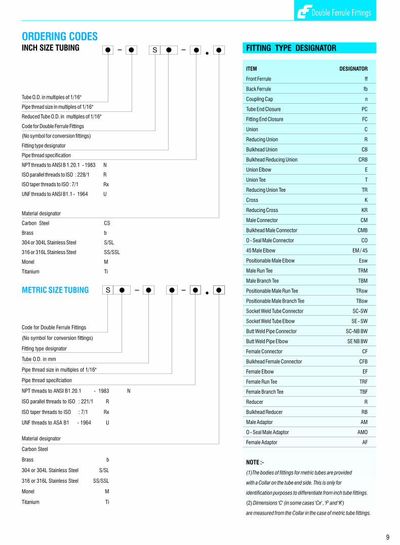
FITTING TYPE DESIGNATOR
ITEM DESIGNATOR
Front Ferrule ff
Back Ferrule fb
Coupling Cap n
Tube End Closure PC
Fitting End Closure FC
Union C
Reducing Union R
Bulkhead Union CB
Bulkhead Reducing Union CRB
Union Elbow E
Union Tee T
Reducing Union Tee TR
Cross K
Reducing Cross KR
Male Connector CM
Bulkhead Male Connector CMB
O - Seal Male Connector CO
o 45 Male Elbow EM / 45
Positionable Male Elbow Esw
Male Run Tee TRM
Male Branch Tee TBM
Positionable Male Run Tee TRsw
Positionable Male Branch Tee TBsw
Socket Weld Tube Connector SC-SW
Socket Weld Tube Elbow SE - SW
Butt Weld Pipe Connector SC-NB BW
Butt Weld Pipe Elbow SE NB BW
Female Connector CF
Bulkhead Female Connector CFB
Female Elbow EF
Female Run Tee TRF
Female Branch Tee TBF
Reducer R
Bulkhead Reducer RB
Male Adaptor AM
O - Seal Male Adaptor AMO
Female Adaptor AF
NOTE :-
(1)The bodies of fittings for metric tubes are provided
with a Collar on the tube end side. This is only for
identification purposes to differentiate from inch tube fittings.
(2) Dimensions 'C' (in some cases 'Cx' , 'F' and 'K')
are measured from the Collar in the case of metric tube fittings.
ORDERING CODES
METRIC SIZE TUBING
INCH SIZE TUBING
Tube O.D. in multiples of 1/16"
Pipe thread size in multiples of 1/16"
Reduced Tube O.D. in multiples of 1/16"
Code for Double Ferrule Fittings
(No symbol for conversion fittings)
Fitting type designator
Pipe thread specification
NPT threads to ANSI B 1.20.1 - 1983 N
ISO parallel threads to ISO : 228/1 R
ISO taper threads to ISO : 7/1 Rx
UNF threads to ANSI B1.1 - 1964 U
Material designator
Carbon Steel CS
Brass b
304 or 304L Stainless Steel S/SL
316 or 316L Stainless Steel SS/SSL
Monel M
Titanium Ti
Titanium Ti
Code for Double Ferrule Fittings
(No symbol for conversion fittings)
Fitting type designator
Tube O.D. in mm
Pipe thread size in multiples of 1/16"
Pipe thread specifciation
NPT threads to ANSI B1.20.1 - 1983 N
ISO parallel threads to ISO : 221/1 R
ISO taper threads to ISO : 7/1 Rx
UNF threads to ASA B1 - 1964 U
Material designator
Carbon Steel Brass b
304 or 304L Stainless Steel S/SL
316 or 316L Stainless Steel SS/SSL
Monel M
S
S
10
Double Ferrule Fittings
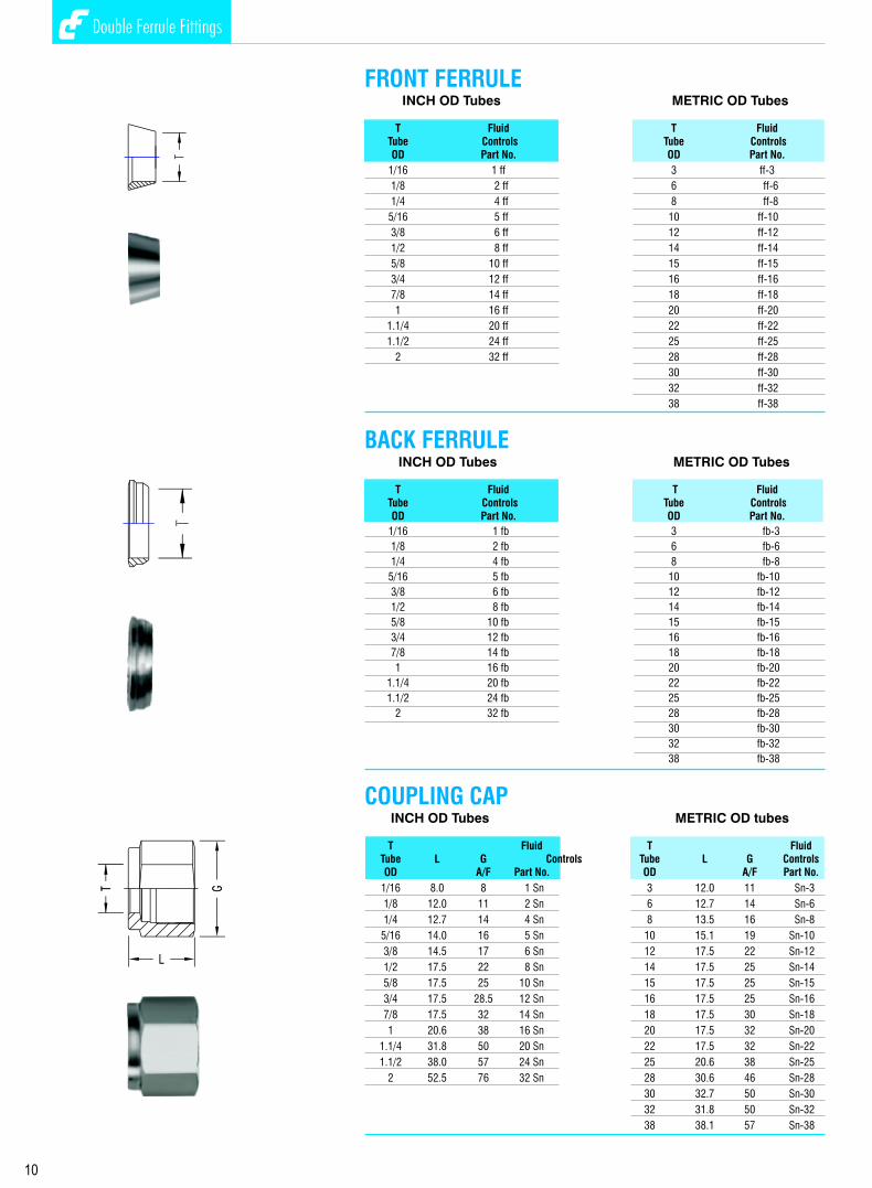
COUPLING CAPINCH OD Tubes METRIC OD tubes
T Fluid T FluidTube L G Controls Tube L G ControlsOD A/F Part No. OD A/F Part No.
1/16 8.0 8 1 Sn 3 12.0 11 Sn-3
1/8 12.0 11 2 Sn 6 12.7 14 Sn-6
1/4 12.7 14 4 Sn 8 13.5 16 Sn-8
5/16 14.0 16 5 Sn 10 15.1 19 Sn-10
3/8 14.5 17 6 Sn 12 17.5 22 Sn-12
1/2 17.5 22 8 Sn 14 17.5 25 Sn-14
5/8 17.5 25 10 Sn 15 17.5 25 Sn-15
3/4 17.5 28.5 12 Sn 16 17.5 25 Sn-16
7/8 17.5 32 14 Sn 18 17.5 30 Sn-18
1 20.6 38 16 Sn 20 17.5 32 Sn-20
1.1/4 31.8 50 20 Sn 22 17.5 32 Sn-22
1.1/2 38.0 57 24 Sn 25 20.6 38 Sn-25
2 52.5 76 32 Sn 28 30.6 46 Sn-28
30 32.7 50 Sn-30
32 31.8 50 Sn-32
38 38.1 57 Sn-38
INCH OD Tubes METRIC OD Tubes
T Fluid T FluidTube Controls Tube ControlsOD Part No. OD Part No.
1/16 1 ff 3 ff-3
1/8 2 ff 6 ff-6
1/4 4 ff 8 ff-8
5/16 5 ff 10 ff-10
3/8 6 ff 12 ff-12
1/2 8 ff 14 ff-14
5/8 10 ff 15 ff-15
3/4 12 ff 16 ff-16
7/8 14 ff 18 ff-18
1 16 ff 20 ff-20
1.1/4 20 ff 22 ff-22
1.1/2 24 ff 25 ff-25
2 32 ff 28 ff-28
30 ff-30
32 ff-32
38 ff-38
INCH OD Tubes METRIC OD Tubes
T Fluid T FluidTube Controls Tube ControlsOD Part No. OD Part No.
1/16 1 fb 3 fb-3
1/8 2 fb 6 fb-6
1/4 4 fb 8 fb-8
5/16 5 fb 10 fb-10
3/8 6 fb 12 fb-12
1/2 8 fb 14 fb-14
5/8 10 fb 15 fb-15
3/4 12 fb 16 fb-16
7/8 14 fb 18 fb-18
1 16 fb 20 fb-20
1.1/4 20 fb 22 fb-22
1.1/2 24 fb 25 fb-25
2 32 fb 28 fb-28
30 fb-30
32 fb-32
38 fb-38
FRONT FERRULE
BACK FERRULE
Double Ferrule Fittings
43
Double Ferrule Fittings
INCH OD Tubes To INCH OD Ports
T Tx FluidTube Tube A C D E F G H ControlsOD OD min. A/F A/F Part No.
1/8 1/8 33.5 15.3 12.7 2.0 11 11 26.9 2 SR
1/8 1/4 36.0 15.3 12.7 4.8 11 11 29.5 2-4 SR
1/4 1/8 36.8 17.8 15.3 2.0 14 14 29.5 4-2 SR
1/4 1/4 39.1 17.8 15.3 4.8 14 14 31.8 4 SR
1/4 3/8 40.6 17.8 15.3 4.8 14 14 33.3 4-6 SR
1/4 1/2 46.3 17.8 15.3 4.8 14 14 38.9 4-8 SR
5/16 3/8 41.9 18.6 16.3 6.3 14 16 34.6 5-6 SR
5/16 1/2 46.5 18.6 16.3 6.3 14 16 40.2 5-8 SR
3/8 1/4 41.4 19.3 16.8 7.1 16 17 34.0 6-4 SR
3/8 3/8 43.2 19.3 16.8 7.1 16 17 35.8 6 SR
3/8 1/2 48.5 19.3 16.8 7.1 16 17 41.2 6-8 SR
1/2 1/4 45.0 21.8 22.9 4.8 22 22 34.8 8-4 SR
1/2 3/8 46.7 21.8 22.9 7.1 22 22 36.6 8-6 SR
1/2 1/2 52.3 21.8 22.9 9.9 22 22 42.2 8 SR
1/2 3/4 53.8 21.8 22.9 10.4 22 22 43.7 8-12 SR
1/2 1 60.2 21.8 22.9 10.4 22 22 50.0 8-16 SR
5/8 3/4 54.6 21.8 24.4 12.7 24 25 44.5 10-12 SR
5/8 7/8 56.2 21.8 24.4 12.7 24 25 46.0 10-14 SR
3/4 1/2 54.6 21.8 24.4 9.9 27 28.5 44.5 12-8 SR
3/4 1 62.5 21.8 24.4 15.8 27 28.5 52.3 12-16 SR
1 1.1/4 80.5 26.4 31.2 22.3 35 38 68.3 16-20 SR
1 1.1/2 89.2 26.4 31.2 22.3 41 38 77.0 16-24 SR
METRIC OD Tubes To METRIC OD Ports
T Tx FluidTube Tube A C D E F G H ControlsOD OD min. A/F A/F Part No.
3 6 36.1 15.3 12.9 2.4 11 11 29.5 SR 3-6
3 10 38.4 15.3 12.9 2.4 14 11 31.8 SR 3-10
6 3 36.9 17.8 15.3 1.8 14 14 29.5 SR 6-3
6 8 39.9 17.8 15.3 4.8 14 14 32.5 SR 6-8
6 10 40.7 17.8 15.3 4.8 14 14 33.3 SR 6-10
6 12 46.3 17.8 15.3 4.8 14 14 38.9 SR 6-12
8 6 40.3 18.6 16.2 4.6 14 16 32.8 SR 8-6
8 10 42.0 18.6 16.2 6.4 14 16 34.5 SR 8-10
8 12 47.6 18.6 16.2 6.4 14 16 40.1 SR 8-12
10 6 42.4 19.5 17.2 4.6 17 17 34.8 SR 10-6
10 8 43.4 19.5 17.2 6.2 17 17 35.8 SR 10-8
10 12 49.8 19.5 17.2 7.9 17 17 42.2 SR 10-12
12 6 44.9 22.0 22.8 4.6 22 22 34.8 SR 12-6
12 8 45.9 22.0 22.8 6.2 22 22 35.8 SR 12-8
12 10 46.7 22.0 22.8 7.7 22 22 36.6 SR 12-10
12 16 53.8 22.0 22.8 9.5 22 22 43.7 SR 12-16
12 20 56.1 22.0 22.8 9.5 22 22 46.0 SR 12-20
12 22 56.1 22.0 22.8 9.5 24 22 46.0 SR 12-22
12 25 62.4 22.0 22.8 9.5 27 22 53.3 SR 12-25
16 12 53.0 22.0 24.4 9.1 24 25 42.9 SR 16-12
18 12 54.6 22.0 24.4 9.1 27 30 44.5 SR 18-12
18 16 56.1 22.0 24.4 12.7 27 30 46.0 SR 18-16
20 16 57.9 22.0 26.0 12.7 30 32 47.8 SR 20-16
20 25 64.2 22.0 26.0 15.8 30 32 54.1 SR 20-25
22 20 59.4 22.0 26.0 15.1 30 32 49.3 SR 22-20
22 25 64.2 22.0 26.0 18.3 30 32 54.1 SR 22-25
25 18 63.1 26.5 31.3 13.9 35 38 50.8 SR 25-18
25 20 64.6 26.5 31.3 15.1 35 38 52.3 SR 25-20
REDUCER

FITTING END CLOSUREINCH OD Tubes METRIC OD Tubes
T Fluid T FluidTube G Controls Tube G ControlsOD A/F Part No. OD A/F Part No.
1/16 8 1 SFC 3 11 SFC-3
1/8 11 2 SFC 6 14 SFC-6
1/4 14 4 SFC 8 16 SFC-8
5/16 16 5 SFC 10 19 SFC-10
3/8 17 6 SFC 12 22 SFC-12
1/2 22 8 SFC 14 25 SFC-14
5/8 25 10 SFC 15 25 SFC-15
3/4 28.5 12 SFC 16 25 SFC-16
7/8 32 14 SFC 18 30 SFC-18
1 38 16 SFC 20 32 SFC-20
1.1/4 50 20 SFC 22 32 SFC-22
1.1/2 57 24 SFC 25 38 SFC-25
2 76 32 SFC 28 46 SFC-28
30 50 SFC-30
32 50 SFC-32
38 57 SFC-38
Double Ferrule Fittings
42
Double Ferrule Fittings
11
INCH OD Tubes
T FluidTube A C D F G H Controls OD A/F A/F Part No.
1/16 13.0 11.0 8.6 11 8 11.2 1 SPC
1/8 20.0 15.3 12.7 11 11 13.5 2 SPC
1/4 23.4 17.8 15.3 14 14 16.0 4 SPC
5/16 24.4 18.5 16.3 16 16 17.0 5 SPC
3/8 25.7 19.3 16.8 17 17 18.3 6 SPC
1/2 29.2 21.8 22.9 22 22 19.0 8 SPC
5/8 30.0 21.8 24.4 24 25 19.8 10 SPC
3/4 31.5 21.8 24.4 27 28.5 21.4 12 SPC
7/8 34.0 21.8 25.9 35 32 23.9 14 SPC
1 38.4 26.4 31.2 35 38 26.2 16 SPC
1.1/4 53.3 38.9 41.2 46 50 31.2 20 SPC
1.1/2 64.5 45.2 50.0 55 57 37.4 24 SPC
2 88.6 62.7 67.6 70.0 76.0 49.3 32 SPC
METRIC OD Tubes
T FluidTube A C D F G H Controls OD A/F A/F Part No.
3 20.1 15.3 12.9 11 11 13.5 SPC-3
6 23.1 17.7 15.3 14 14 15.7 SPC-6
8 24.5 18.6 16.2 16 16 17.0 SPC-8
10 26.6 19.5 17.2 17 19 19.0 SPC-10
12 29.1 22.0 22.8 22 22 19.0 SPC-12
14 29.9 22.0 24.4 24 25 19.8 SPC-14
15 29.9 22.0 24.4 24 25 19.8 SPC-15
16 29.9 22.0 24.4 24 25 19.8 SPC-16
18 31.4 22.0 24.4 27 30 21.3 SPC-18
20 34.0 22.0 26.0 32 32 23.9 SPC-20
22 34.0 22.0 26.0 32 32 23.9 SPC-22
25 38.5 26.5 31.3 35 38 26.2 SPC-25
28 48.5 36.6 36.6 41 46 27.7 SPC-28
30 53.4 39.2 39.6 46 50 31.8 SPC-30
32 55.8 41.6 42.0 46 50 32.8 SPC-32
38 65.4 47.9 49.4 55 57 37.8 SPC-38
TUBE END CLOSURESOCKET WELD TUBE CONNECTOR
SOCKET WELD TUBE ELBOW
INCH OD Tubes
T F G FluidTube A B Bx C D E A/F A/F H J ControlsOD min. Part No.
1/8 29.0 8.6 6.4 15.3 12.7 2.4 11 11 22.9 7.9 2 SC- SW
1/4 33.5 10.4 7.9 17.8 5.3 4.8 14 14 26.2 11.2 4 SC- SW
3/8 37.6 12.0 9.6 19.3 16.8 7.1 16 17 30.3 15.8 6 SC- SW
1/2 41.2 12.0 12.7 21.8 22.9 10.4 22 22 31.0 19.1 8 SC- SW
3/4 43.4 12.0 14.3 21.8 24.4 15.8 27 28.5 33.3 26.7 12 SC- SW
1 52.6 14.3 19.1 26.4 31.2 22.3 35 38 40.4 33.3 16 SC- SW
1.1/4 72.4 19.1 19.1 38.9 41.2 27.6 45 50 50.3 42.0 20 SC- SW
1.1/2 81.8 19.1 23.8 45.2 50.0 34.0 55 57 54.6 50.0 24 SC- SW
METRIC OD Tubes
T F G FluidTube A B Bx C D E A/F A/F H J ControlsOD min. Part No.
3 29.0 8.6 6.4 15.3 12.9 2.4 11 11 22.9 7.9 SC-3- SW
6 33.5 10.4 7.9 17.7 15.3 4.8 14 14 26.2 11.2 SC-6- SW
10 37.6 12.0 9.6 19.5 17.2 7.1 16 17 30.3 15.8 SC-10- SW
12 41.2 12.0 12.7 22.0 22.8 10.4 22 22 31.0 19.1 SC-12- SW
20 43.4 12.0 14.3 22.0 26.0 15.8 27 28.5 33.3 26.7 SC-20- SW
25 52.6 14.3 19.1 26.5 31.3 22.3 35 38 40.4 33.3 SC-25- SW
32 72.4 19.1 19.1 41.6 42.0 27.6 45 50 50.3 42.0 SC-32- SW
38 81.8 19.1 23.8 47.9 49.4 34.0 55 57 54.6 50.0 SC-38- SW
INCH OD Tubes
T F G FluidTube A Bx C D E A/F A/F Hx Hy K ControlsOD min. Part No.
1/4 27.0 7.9 17.8 15.3 4.8 14 14 19.6 19.6 12.7 4 SE- SW
3/8 30.5 9.6 19.3 16.8 7.1 16 17 23.1 23.1 15.8 6 SE- SW
1/2 36.0 12.7 21.8 22.9 10.4 22 22 25.9 25.9 20.6 8 SE- SW
34 39.9 14.3 21.8 24.4 15.8 27 28.5 29.7 29.7 27.0 12 SE- SW
1 49.0 19.1 26.4 31.2 22.3 35 38 36.8 36.8 35.0 16 SE- SW
1.1/4 66.5 19.1 38.9 41.2 27.6 45 50 44.5 47.8 43.0 20 SE- SW
1.1/2 78.0 23.8 45.2 50.0 34.0 50 57 50.8 60.4 48.0 24 SE- SW
METRIC OD Tubes
T F G FluidTube A B Bx C D E A/F A/F H J ControlsOD min. Part No.
6 27.0 7.9 17.7 15.3 4.8 14 14 19.6 19.6 12.7 SE-6- SW
10 30.5 9.6 19.5 17.2 7.1 16 17 23.1 23.1 15.8 SE-10- SW
12 36.0 12.7 22.0 22.8 10.4 22 22 25.9 25.9 20.6 SE-12- SW
20 39.9 14.3 22.0 26.0 15.8 27 28.5 29.7 29.7 27.0 SE-20- SW
25 49.0 19.1 26.5 31.3 22.3 35 38 36.8 36.8 35.0 SE-25- SW
32 66.5 19.1 41.6 42.0 27.6 45 50 44.5 47.8 43.0 SE-32- SW
38 78.0 23.8 47.9 49.4 34.0 50 57 50.8 60.4 48.0 SE-38- SW
NOTE: Available with socket welded connection for pipes.
NOTE: Socket weld Tube-to-pipe connections for inch and metric OD tubes to socket weld connections for pipes to ANSI B39.19, BS:1387, DIN:239, IS:1239 also available. Please consult us.

Double Ferrule Fittings Double Ferrule Fittings
12 41
BUTT WELD PIPE CONNECTORINCH OD Tubes to Pipe*
T Pipe Fluid Tube Weld A B C D E F G H J ControlsOD Male min. A/F A/F Part No.
1/8 1/8 30.5 9.6 15.3 12.7 2.4 11 11 23.9 10.3 2 SC-NB BW
1/4 1/8 32.8 9.6 17.8 15.3 4.8 14 14 25.4 10.3 4-2 CS-NB BW
1/4 1/4 37.8 14.3 17.8 15.3 4.8 14 14 30.5 13.7 4 SC-NB BW
5/16 1/8 34.0 9.6 18.5 16.3 5.1 14 16 26.7 10.3 5-2 SC-NB BW
5/16 1/4 38.6 14.3 18.5 16.3 6.3 16 16 31.2 13.7 5-4 SC-NB BW
3/8 1/4 39.9 14.3 19.3 16.8 7.1 16 17 32.5 13.7 6-4 SC-NB BW
3/8 3/8 39.9 14.3 19.3 16.8 7.1 17 17 32.5 17.2 6 SC-NB BW
3/8 1/2 46.3 19.1 19.3 16.8 7.1 22 17 38.9 21.3 6-8 SC-NB BW
1/2 3/8 43.4 14.3 21.8 22.9 10.4 22 22 33.3 17.2 8-6 SC-NB BW
1/2 1/2 49.0 19.1 21.8 22.9 10.4 22 22 38.9 21.3 8 SC-NB BW
1/2 3/4 50.5 19.1 21.8 22.9 10.4 27 22 40.4 26.7 8-12 SC-NB BW
5/8 1/2 49.0 19.1 21.8 24.4 12.7 24 25 38.9 21.3 10-8 SC-NB BW
3/4 3/4 50.5 19.1 21.8 24.4 15.8 27 29 40.4 26.7 12 SC-NB BW
1 1 62.2 23.8 26.4 31.2 22.3 35 38 50.0 33.4 16 SC-NB BW
1.1/4 1.1/4 77.2 23.8 38.9 41.2 27.6 46 50 55.2 42.2 20 SC-NB BW
1.1/2 1.1/2 88.9 26.2 45.2 50.0 34 55 60 61.7 48.3 24 SC-NB BW
METRIC OD Tubes to Pipe*
T Pipe Fluid Tube Weld A B C D E F G H J ControlsOD Male min. A/F A/F Part No.
3 1/8 30.5 9.6 15.3 12.9 2.4 11 11 23.9 10.3 SC-NB BW-3-2
6 1/8 32.8 9.6 17.8 15.3 4.8 14 14 25.4 10.3 SC-NB BW-6-2
6 1/4 37.9 14.3 17.8 15.3 4.8 14 14 30.5 13.7 SC-NB BW-6-4
8 1/8 34.2 9.6 18.5 16.3 5.1 16 16 26.7 10.3 SC-NB BW-8-2
8 1/4 38.7 14.3 18.5 16.3 6.3 16 16 31.2 13.7 SC-NB BW-8-4
8 1/2 45.6 19.1 18.5 16.3 6.3 22 16 38.1 21.3 SC-NB BW-8
10 1/4 40.9 14.3 19.5 17.2 7.1 19 19 33.3 13.7 SC-NB BW-10-4
10 3/8 40.9 14.3 19.5 17.2 7.9 19 19 33.3 17.2 SC- NB BW-10-6
10 1/2 46.5 19.1 19.5 17.2 7.9 22 19 38.9 21.3 SC-NB BW-10-8
12 1/4 43.4 14.3 22.0 22.9 7.1 22 22 33.3 13.7 SC-NB BW-12-4
12 3/8 43.4 14.3 22.0 22.9 9.5 22 22 33.3 17.2 SC-NB BW-12-6
12 1/2 49.0 19.1 22.0 22.9 9.5 22 22 38.9 21.3 SC-NB BW-12
16 1/2 49.0 19.1 22.0 24.4 12.7 24 25 38.9 21.3 SC-NB BW-16-8
20 3/4 52.3 19.1 22.0 26 15.9 30 32 42.2 26.7 SC-NB BW-20-12
22 3/4 52.3 19.1 22.0 26 15.9 30 32 42.2 26.7 SC-NB BW-22-12
25 1 62.3 23.8 26.5 31.3 21.8 35 38 50.0 33.4 SC-NB BW-25-16
30 1.1/4 77.2 23.8 39.2 39.6 26.2 45 50 55.6 42.2 SC-NB BW-30-20
32 1.1/4 79.6 23.8 41.6 42.0 28.6 45 50 56.6 42.2 SC-NB BW-32-20
38 1.1/2 91.6 26.2 47.9 49.4 33.7 55 57 64.0 48.3 SC-NB BW-38-24
BUTT WELD PIPE ELBOW INCH OD Tubes to Pipe*
T Pipe Fluid Tube Weld A B C D E F G Hx Hy J ControlsOD Male min. A/F A/F Part No.
1/4 1/8 27.0 9.6 17.8 15.3 4.8 14 14 19.6 18.8 10.3 4-2 SE-NB BW
1/4 1/4 27.0 14.3 17.8 15.3 4.8 14 14 19.6 23.4 13.7 4 SE-NB BW
3/8 1/4 30.5 14.3 19.3 16.8 7.1 16 17 23.1 25.9 13.7 6-4 SE-NB BW
1/2 1/2 36.0 19.1 21.8 22.9 10.4 22 22 25.9 33.0 21.3 8 SE-NB BW
3/4 3/4 39.9 19.1 21.8 24.4 15.8 27 29 29.7 36.8 26.7 12 SE-NB BW
1 1 49.0 23.8 26.4 31.2 22.3 35 38 36.8 46.5 33.4 16 SE-NB BW
1.1/4 1.1/4 66.5 23.8 38.9 41.2 27.6 45 50 44.5 47.8 42.2 20 SE-NB BW
1.1/2 1.1/2 78.0 26.2 45.2 50.0 34.0 50 57 50.8 60.5 48.3 24 SE-NB
* Reference specification : ANSI B36.19, BS:1387, DIN2391, IS:1239
12
INCH OD Tubes
T FluidTube A C D E F G H ControlsOD min. A/F A/F Part No.
1/16 25.1 11.0 8.6 1.3 8 8 17.5 1 SC
1/8 35.6 15.3 12.7 2.4 11 11 22.4 2 SC
1/4 40.9 17.8 15.3 4.8 14 14 26.2 4 SC
5/16 42.9 18.5 16.3 6.3 14 16 28.2 5 SC
3/8 45.0 19.3 16.8 7.1 16 17 30.2 6 SC
1/2 51.3 21.8 22.9 10.4 22 22 31.0 8 SC
5/8 52.0 21.8 24.4 12.7 24 25 31.8 10 SC
3/4 53.6 21.8 24.4 15.8 27 28.5 33.3 12 SC
7/8 55.2 21.8 25.9 18.2 30 32 34.8 14 SC
1 64.8 26.4 31.2 22.3 35 38 40.4 16 SC
1.1/4 92.2 38.9 41.2 27.6 46 50 48.0 20 SC
1.1/2 108.0 45.2 50.0 34.0 55 57 53.6 24 SC
2 149.4 62.7 67.6 46.0 70 76 74.7 32 SC
METRIC OD Tubes
T FluidTube A C D E F G H ControlsOD min. A/F A/F Part No.
3 35.3 15.3 12.9 2.4 11 11 22.1 SC-3
6 41.0 17.7 15.3 4.8 14 14 26.2 SC-6
8 43.2 18.6 16.2 6.3 16 16 28.2 SC-8
10 46.2 19.5 17.2 7.9 17 19 31.0 SC-10
12 51.2 22.0 22.8 9.5 22 22 31.0 SC-12
14 52.0 22.0 24.4 11.1 24 25 31.0 SC-14
15 52.0 22.0 24.4 11.9 24 25 31.8 SC-15
16 52.0 22.0 24.4 12.7 24 25 31.8 SC-16
18 53.5 22.0 24.4 15.1 27 30 33.3 SC-18
20 55.0 22.0 26.0 15.9 30 32 34.8 SC-20
22 55.0 22.0 26.0 18.3 30 32 34.8 SC-22
25 65.0 26.5 31.3 21.8 35 38 40.4 SC-25
28 85.0 36.6 36.6 21.8 41 46 43.4 SC-28
30 92.7 39.2 39.6 26.2 46 50 49.5 SC-30
32 97.3 41.6 42.0 28.6 46 50 51.3 SC-32
38 113.6 47.9 49.4 33.7 55 57 58.4 SC-38
UNION

Double Ferrule Fittings Double Ferrule Fittings
13
REDUCING UNION INCH OD Tubes
T Tx FluidTube Tube A C Cx D Dx E F G Gx H ControlsOD OD min. A/F A/F A/F Part No.
1/4 1/8 38.6 17.8 15.3 15.3 12.7 2.4 14 14 11 24.6 4-2 SCR
5/16 1/8 39.6 18.6 15.3 16.3 12.7 2.4 14 16 11 25.7 5-2 SCR
5/16 1/4 42.2 18.6 17.8 16.3 15.3 4.8 14 16 14 27.5 5-4 SCR
3/8 1/8 40.9 19.3 15.3 16.8 12.7 2.4 16 17 11 26.9 6-2 SCR
3/8 1/4 43.2 19.3 17.8 16.8 15.3 4.8 16 17 14 28.5 6-4 SCR
1/2 1/8 45.2 21.8 15.3 22.9 12.7 2.4 22 22 11 28.5 8-2 SCR
1/2 1/4 47.0 21.8 17.8 22.9 15.3 4.8 22 22 14 29.5 8-4 SCR
1/2 3/8 48.5 21.8 19.3 22.9 16.8 7.1 22 22 17 31.0 8-6 SCR
5/8 3/8 49.3 21.8 19.3 24.4 16.8 7.1 24 25 17 31.8 10-6 SCR
5/8 1/2 52.0 21.8 21.8 24.4 22.9 10.4 24 25 22 31.8 10-8 SCR
3/4 1/4 49.3 21.8 17.8 24.4 15.3 4.8 27 28.5 14 31.8 12-4 SCR
3/4 3/8 50.8 21.8 19.3 24.4 16.8 7.1 27 28.5 17 33.3 12-6 SCR
3/4 1/2 53.6 21.8 21.8 24.4 22.9 10.4 27 28.5 22 33.3 12-8 SCR
1 1/2 60.5 26.5 21.8 31.2 22.9 10.4 35 38 22 38.1 16-8 SCR
1 3/4 60.5 26.5 21.8 31.2 24.4 15.8 35 38 28.5 38.1 16-12 SCR
1.1/4 1 92.2 38.9 26.4 41.2 31.2 22.3 45 50 38 48.0 20-16 SCR
1.1/2 1.1/4 60.5 26.5 21.8 31.2 24.4 15.8 55 57 50 53.6 24-20 SCR
METRIC OD Tubes
T Tx FluidTube Tube A C Cx D Dx E F G Gx H ControlsOD OD min. A/F A/F A/F Part No.
6 3 38.6 17.7 15.3 15.3 12.9 2.4 14 14 11 24.6 SCR 6-3
8 6 42.3 18.6 17.7 16.2 15.3 4.8 14 16 14 27.4 SCR 8-6
10 6 44.5 19.5 17.7 17.2 15.3 4.8 17 19 14 29.5 SCR 10-6
10 8 45.1 19.5 18.6 17.2 16.2 6.3 17 19 16 30.0 SCR 10-8
12 6 47.0 22.0 17.7 22.8 15.3 4.8 22 22 14 29.5 SCR 12-6
12 8 47.8 22.0 18.6 22.8 16.2 6.4 22 22 16 30.2 SCR 12-8
12 10 48.7 22.0 19.5 22.8 17.2 7.9 22 22 19 31.0 SCR 12-10
16 10 49.5 22.0 19.5 24.4 17.2 7.9 24 25 19 31.8 SCR 16-10
16 12 52.0 22.0 22.0 24.4 22.8 9.5 24 25 22 31.8 SCR 16-12
22 18 55.0 22.0 22.0 26.0 24.4 15.1 30 32 30 34.8 SCR 22-18
22 20 55.0 22.0 22.0 26.0 26.6 15.9 30 32 32 34.8 SCR 22-20
25 12 65.0 26.5 22.0 31.3 22.8 9.5 35 38 22 40.4 SCR 25-12
25 20 65.0 26.5 22.0 31.3 26.0 15.9 35 38 32 40.4 SCR 25-20
30 20 75.4 39.2 22.0 39.6 26.0 15.9 45 50 32 43.7 SCR 30-20
30 25 80.1 39.2 26.5 39.6 31.3 21.8 45 50 38 46.2 SCR 30-25
32 20 77.8 41.6 22.0 42.0 26.0 15.9 45 50 32 44.7 SCR 32-20
32 25 82.3 41.6 26.5 42.0 31.3 21.8 45 50 38 47.0 SCR 32-25
38 20 92.0 47.9 26.5 49.4 31.3 21.8 55 57 38 52.1 SCR 38-20
38 25 104.6 47.9 39.2 49.4 39.6 26.2 55 57 50 55.4 SCR 38-25
FEMALE BRANCH TEE INCH OD Tubes X Female NPT Threads
T P F G FluidTube NPT A Ax B C D E A/F A/F H Hx Hy ControlsOD Female min. Part No.
1/8 1/8 49.2 24.6 10.4 15.3 12.7 2.4 14 11 36.0 18.0 19.0 2 STBF-N
1/4 1/8 53.8 26.9 10.4 17.8 15.3 4.8 14 14 39.2 19.6 19.0 4-2 STBF-N
1/4 1/4 59.4 27.9 15.0 17.8 15.3 4.8 19 14 44.8 22.4 22.4 4 STBF-N
3/8 1/4 62.4 31.2 15.0 19.3 16.8 7.1 16 16 47.8 23.9 22.4 6-4 STBF-N
3/8 3/8 66.6 33.3 15.0 19.3 16.8 7.1 19 16 51.8 25.9 22.4 6 STBF-N
1/2 3/8 72.0 36.0 15.0 21.8 22.9 10.4 19 19 51.8 25.9 22.4 8-6 STBF-N
1/2 1/2 77.8 38.9 19.8 21.8 22.9 10.4 22 22 57.4 28.7 28.5 8 STBF-N
3/4 3/4 89.4 44.7 20.6 21.8 24.4 15.8 35 22 69.2 34.6 31.8 12 STBF-N
1 3/4 98.0 49.0 20.6 26.4 31.2 22.3 35 25 73.6 36.8 31.8 16-12 STBF-N
1 1 107.2 53.6 25.4 26.4 31.2 22.3 41 38 82.8 41.4 38.1 16 STBF-6N
METRIC Tubes X Female NPT Threads
T P F G FluidTube NPT A Ax B C D E A/F A/F H Hx Hy ControlsOD Female min. Part No.
3 1/8 49.2 24.6 10.4 15.3 12.9 2.4 14 11 36.0 18.0 19.0 STBF 3-2N
6 1/8 54.0 27.0 10.4 17.7 15.3 4.8 14 14 39.2 19.6 19.0 STBF 6-2N
6 1/4 59.6 29.8 15.0 17.7 15.3 4.8 19 14 44.8 22.4 22.4 STBF 6-4N
8 1/8 59.8 29.9 10.4 18.6 16.2 6.3 16 16 44.8 22.4 19.0 STBF 8-2N
8 1/4 61.2 30.6 15.0 18.6 16.2 6.3 19 16 46.2 23.1 22.4 STBF 8-4N
10 1/4 67.0 33.5 15.0 19.5 17.2 7.9 19 19 51.8 25.9 22.4 STBF 10-4N
12 3/8 72.0 36.0 15.0 22.0 22.8 9.5 22 22 51.8 25.9 22.4 STBF 12-6N
12 1/2 77.6 38.8 19.8 22.0 22.8 9.5 27 22 57.4 28.7 28.5 STBF 12-8N
16 1/2 79.0 39.5 19.8 22.0 24.4 12.7 27 25 59.4 29.7 28.5 STBF 16-8N
25 1 107.2 53.6 25.4 26.5 31.3 22.3 41 38 82.8 41.4 38.1 STBF 25-16N
FEMALE RUN TEE INCH OD Tubes X Female NPT Threads
T P F G FluidTube NPT A Ax B C D E A/F A/F H Hx Hy ControlsOD Female min. Part No.
1/8 1/8 43.6 24.6 10.4 15.3 12.7 2.4 14 11 37.0 18.0 19.0 2 STRF-N
1/4 1/8 45.9 26.9 10.4 17.8 15.3 4.8 14 14 38.6 19.6 19.0 4-2 STRF-N
1/4 1/4 52.1 29.7 15.0 17.8 15.3 4.8 19 14 44.8 22.4 22.4 4 STRF-N
3/8 1/4 53.6 31.2 15.0 19.3 16.8 7.1 19 17 46.3 23.9 22.4 6-4 STRF-N
3/8 3/8 55.7 33.3 15.0 19.3 16.8 7.1 22 17 48.3 25.9 22.4 6 STRF-N
1/2 3/8 58.4 36.0 15.0 21.8 22.9 10.4 22 22 48.3 25.9 22.4 8-6 STRF-N
1/2 1/2 67.4 38.9 19.8 21.8 22.9 10.4 27 22 57.2 28.7 28.5 8 STRF-N
3/4 3/4 76.5 44.7 20.6 21.8 24.4 15.8 35 29 66.4 34.6 31.8 12 STRF-N
1 3/4 80.8 49.0 20.6 26.4 31 22.3 35 38 68.6 36.8 31.8 16-12 STRF-N
1 1 91.7 53.6 25.4 26.4 31 22.3 41 38 79.5 41.4 38.1 16 STRF-N
METRIC OD Tubes X Female NPT Threads
T P F G FluidTube NPT A Ax B C D E A/F A/F H Hx Hy ControlsOD Female min. Part No.
3 1/8 43.6 24.6 10.4 15.3 12.9 2.4 14 11 37.0 18.0 19.0 STRF 3-2N
6 1/8 46.0 27.0 10.4 17.7 15.3 4.8 14 14 38.6 19.6 19.0 STRF 6-2N
6 1/4 52.2 29.8 15.0 17.7 15.3 4.8 19 14 44.8 22.4 22.4 STRF 6-4N
8 1/8 48.9 29.9 10.4 18.6 16.2 6.3 16 16 41.4 22.4 19.0 STRF 8-2N
8 1/4 53.0 30.6 15.0 18.6 16.2 6.3 19 16 45.5 23.1 22.4 STRF 8-4N
10 1/4 55.9 33.5 15.0 19.5 17.2 7.9 19 19 48.3 25.9 22.4 STRF 10-4N
12 3/8 58.4 36.0 15.0 22.0 22.8 9.5 22 22 48.3 25.9 22.4 STRF 12-6N
12 1/2 67.3 38.8 19.8 22.0 22.8 9.5 27 22 57.2 28.7 28.5 STRF 12-8N
16 1/2 68.0 39.5 19.8 22.0 24 12.7 27 25 58.2 29.7 28.5 STRF 16-8N
25 1 91.7 53.6 25.4 26.5 31.3 22.3 41 38 79.5 41.4 38.1 STRF 25-16N
40
NOTE: The combinations shown above are representative of various possibilities. Other combinations not shown are also available. Please consult us.
NOTE: Bulkhead Female Connectors are also available with ISO Taper Female Threads, ISO Parallel Female Threads and ISO Female Marcometer connection. Please consult us.
NOTE: The combinations shown above are representative of various possibilities. Other combinations not shown are also available. Please consult us.

Double Ferrule Fittings Double Ferrule Fittings
14
BULKHEAD UNIONINCH OD Tubes
T Panel Max. FluidTube A Ax C D E F G H Hx Hole Panel ControlsOD min. A/F A/F Drill Thick- Part No.
Size ness
1/16 31.5 17.3 11.0 8.6 1.3 11 8 23.8 13.5 5.2 3.0 1 SCB
1/8 51.3 31.2 15.3 12.7 2.4 11 11 38.1 24.6 8.3 12.7 2 SCB
1/4 57.6 33.6 17.8 15.3 4.8 16 14 43.0 26.2 11.5 10.1 4 SCB
5/16 60.7 35.8 18.5 16.3 6.3 17 16 46.0 28.5 13.0 11.1 5 SCB
3/8 62.2 36.8 19.3 7.1 7.1 22 17 47.5 29.5 14.6 11.1 6 SCB
1/2 71.1 41.9 21.8 22.9 10.4 24 22 50.8 31.8 19.5 12.7 8 SCB
5/8 72.6 42.7 21.8 24.4 12.7 27 25 52.3 32.5 22.6 12.7 10 SCB
3/4 79.0 47.5 21.8 24.4 16.0 30 28.5 58.6 37.4 25.8 16.8 12 SCB
1 95.6 57.4 26.4 31.2 22.3 35 38 71.3 45.2 33.7 19.0 16 SCB
1.1/4 123.2 69.9 38.9 41.2 27.6 50 50 79.0 47.7 41.6 19.0 20 SCB
1.1/2 139.2 76.4 45.2 50.0 34.0 60 57 84.8 49.3 49.6 19.0 24 SCB
2 180.4 93.7 62.7 67.6 46.0 70 76 105.6 56.4 67.0 19.0 32 SCB
METRIC OD Tubes
T Panel Max. FluidTube A Ax C D E F G H Hx Hole Panel ControlsOD min. A/F A/F Drill Thick- Part No.
Size ness
3 51.3 31.2 15.3 12.9 2.4 14 11 38.1 24.6 8.3 12.7 SCB-3
6 57.7 33.6 17.7 15.3 4.8 16 14 42.9 26.2 11.5 10.2 SCB-6
8 61.0 36.1 18.6 16.2 6.3 17 16 46.0 28.6 13.1 11.2 SCB-8
10 63.7 37.0 19.5 17.2 7.9 22 19 48.5 29.4 16.3 11.2 SCB-10
12 71.0 41.9 22.0 22.8 9.5 24 22 50.8 31.8 19.5 12.7 SCB-12
14 72.5 42.6 22.0 24.4 11.1 27 25 52.3 32.5 22.5 12.7 SCB-14
15 72.5 42.6 22.0 24.4 11.9 27 25 52.3 32.5 22.8 12.7 SCB-15
16 72.5 42.6 22.0 24.4 12.7 27 25 52.3 32.5 22.8 12.7 SCB-16
18 78.9 47.4 22.0 24.4 15.1 30 30 58.7 37.3 26.0 16.8 SCB-18
20 84.5 53.0 22.0 26.0 15.8 35 32 64.3 42.9 29.0 19.0 SCB-20
25 95.6 57.4 26.4 31.2 22.3 35 38 71.3 45.2 33.7 19.0 SCB-25
30 123.7 70.2 39.2 39.6 26.2 50 46 80.5 48.6 40.5 19.0 SCB-30
32 128.3 72.5 41.6 42.0 27.6 50 50 82.3 49.5 42.5 19.0 SCB-32
38 144.6 79.1 47.9 49.4 33.7 60 57 89.4 51.5 50.5 19.0 SCB-38
BULKHEAD REDUCING UNIONINCH OD Tubes
T T Panel Max. FluidTube Tube A Ax Cx D Dx E F G Gx H Hx Hole Panel ControlsOD OD min. A/F A/F A/F Drill Thick- Part No.
Size ness
1/4 1/8 55.2 33.5 15.3 15.3 12.7 2.4 16 14 11 41.2 26.2 11.5 10.2 4-2 SCRB
3/8 1/4 60.7 36.6 17.8 16.8 15.3 4.8 22 17 14 46.0 29.5 14.6 11.2 6-4 SCRB
1/2 1/4 66.8 41.9 17.8 22.4 15.3 4.8 24 22 14 49.2 31.8 19.5 12.7 8-4 SCRB
1/2 3/8 66.8 41.9 17.8 22.4 16.8 7.1 24 22 17 49.2 31.8 19.5 12.7 8-6 SCRB
METRIC OD Tubes
T T Panel Max. FluidTube Tube A Ax Cx D Dx E F G Gx H Hx Hole Panel ControlsOD OD min. A/F A/F A/F Drill Thick- Part No.
Size ness
6 3 56.0 33.6 17.7 15.3 12.9 2.4 16 14 11 41.2 26.2 11.5 10.2 SCRB-6-3
8 6 61.0 36.1 18.6 16.2 15.3 4.8 17 16 14 48.0 28.6 13.1 11.2 SCRB-8-6
10 6 63.7 37.0 19.5 17.2 15.3 4.8 22 19 14 48.5 29.4 16.3 11.2 SCRB-10-6
12 6 71.0 41.9 22.0 22.8 15.3 4.8 24 22 14 50.8 31.8 19.5 12.7 SCRB-12-6
12 10 71.0 41.9 22.0 22.8 17.2 7.9 24 22 17 50.8 31.8 19.5 12.7 SCRB-12-10
FEMALE ELBOW INCH OD Tubes X Female ISO* tapered pipe threads
T P F G FluidTube NPT A B C D E A/F A/F Hx Hy ControlsOD Female min. Part No.
1/8 1/8 24.6 10.4 15.3 12.7 2.4 14 11 18.0 19.0 2 SEF-Rx
1/8 1/4 27.4 15.0 15.3 12.7 2.4 19 11 20.8 22.4 2-4 SEF-Rx
1/4 1/8 26.9 10.4 17.8 15.3 4.8 14 14 19.6 19.0 4-2 SEF-Rx
1/4 1/4 29.7 15.0 17.8 15.3 4.8 19 14 22.4 22.4 4 SEF-Rx
1/4 3/8 31.8 15.0 17.8 15.3 4.8 22 14 24.4 22.4 4-6 SEF--Rx
1/4 1/2 34.6 19.8 17.8 15.3 4.8 27 14 27.2 28.5 4-8 SEF-Rx
5/16 1/8 28.7 10.4 17.8 15.3 6.3 19 14 21.4 19.1 5-2 SEF-Rx
5/16 1/4 30.5 15.0 18.5 16.3 6.3 22 16 23.2 22.4 5-4 SEF-Rx
3/8 1/8 30.5 10.4 19.3 16.8 7.1 17 17 23.2 19.1 6-2 SEF-Rx
3/8 1/4 31.2 15.0 19.3 16.8 7.1 19 17 23.9 22.4 6-4 SEF-Rx
3/8 3/8 33.3 15.0 19.3 16.8 7.1 22 17 25.9 22.4 6 SEF-Rx
3/8 1/2 36.0 19.8 19.3 16.8 7.1 27 17 28.7 28.5 6-8 SEF-Rx
1/2 1/4 36.0 15.0 21.8 22.9 7.1 22 22 25.9 22.4 8-4 SEF-Rx
1/2 3/8 36.0 15.0 21.8 22.9 10.4 22 22 25.9 22.4 8-6 SEF-Rx
1/2 1/2 38.9 19.8 21.8 22.9 10.4 27 22 28.7 28.5 8 SEF-Rx
5/8 3/8 38.1 15.0 21.8 22.9 12.7 24 22 28.0 22.4 10-6 SEF-Rx
5/8 1/2 39.9 19.8 21.8 24.4 12.7 27 25 29.7 28.5 10-8 SEF-Rx
3/4 1/2 39.9 19.8 21.8 24.4 15.8 27 28.5 29.7 28.5 12-8 SEF-Rx
3/4 3/4 44.7 20.6 21.8 24.4 15.8 35 28.5 34.6 31.8 12 SEF-Rx
7/8 3/4 44.7 20.6 21.8 25.9 18.2 35 32 34.6 31.8 14-12 SEF-Rx
1 3/4 49.0 20.6 26.4 31.2 22.3 35 38 36.8 31.8 16-12 SEF-Rx
1 1 53.6 25.4 26.4 31.2 22.3 41 38 41.4 38.1 16 SEF-Rx
METRIC OD Tubes x Female ISO* tapered pipe threads
T P F G FluidTube NPT A B C D E A/F A/F Hx Hy ControlsOD Female min. Part No.
3 1/8 24.6 10.4 15.3 12.9 2.4 14 11 18.0 19.0 SEF 3-2Rx
3 1/4 27.4 15.0 15.3 12.9 2.4 19 11 20.8 22.4 SEF 3-4Rx
6 1/8 27.0 10.4 17.7 15.3 4.8 14 14 19.6 19.0 SEF 6-2Rx
6 1/4 29.8 15.0 17.7 15.3 4.8 19 14 22.4 22.4 SCF 6-4Rx
6 1/2 34.6 19.8 17.7 15.3 4.8 27 14 27.2 28.5 SEF 6-8Rx
8 1/4 30.6 15.0 18.6 16.2 6.3 19 16 23.1 22.4 SEF 8-4Rx
8 3/8 32.6 15.0 18.6 16.2 6.3 22 16 25.1 22.4 SEF 8-6Rx
10 1/4 33.5 15.0 19.5 17.2 7.9 19 19 25.9 22.4 SEF 10-4Rx
10 3/8 33.5 15.0 19.5 17.2 7.9 22 19 25.9 22.4 SEF 10-6Rx
12 1/4 36.0 15.0 22.0 22.8 9.5 22 22 25.9 22.4 SEF 12-4Rx
12 3/8 36.0 15.0 22.0 22.8 9.5 22 22 25.9 22.4 SEF 12-6Rx
12 1/2 38.8 19.8 22.0 22.8 9.5 27 22 28.7 28.5 SEF 12-8Rx
16 1/2 39.5 19.8 22.0 24.4 12.7 27 25 29.7 28.5 SEF 16-8Rx
25 3/4 49.0 20.6 26.5 31.3 22.3 35 38 36.8 31.8 SEF 25-12Rx
25 1 53.6 25.4 26.5 31.3 22.3 41 38 41.4 38.1 SEF 25-16Rx
39
NOTE: The combinations shown above are representative of various possibilities. Other combinations not shown are also available. Please consult us.
* Reference Specifications : BS 21: ISO 7/1 : JIS B 0203 : DIN 2999 : IS 554
* Female connectors with Parallel ISO Female Threads to BS:2779; ISO 228/1; JIS B6202; DIN 259 are also available. Their Dimensions are as same as ISO. Tapered Pipe Threads above. Pleae consult us.

Double Ferrule Fittings Double Ferrule Fittings
15
INCH OD Tubes
T FluidTube A C D E F G Hx ControlsOD min. A/F Part No.
1/16 17.8 11.0 8.6 1.3 11 8 14.0 1 SE
1/8 22.4 15.3 12.7 2.4 11 11 15.8 2 SE
1/4 26.9 17.8 15.3 4.8 14 14 19.6 4 SE
5/16 28.7 18.5 16.3 6.3 16 16 21.3 5 SE
3/8 30.5 19.3 16.8 7.1 17 17 23.2 6 SE
1/2 36.0 21.8 22.9 10.4 22 22 25.9 8 SE
5/8 38.1 21.8 24.4 12.7 24 25 27.9 10 SE
3/4 39.9 21.8 24.4 15.8 27 28.5 29.7 12 SE
7/8 44.7 21.8 25.9 18.2 35 32 34.6 14 SE
1 49.0 26.4 31.2 22.3 35 38 36.8 16 SE
1.1/4 66.6 38.9 41.2 27.6 46 50 44.5 20 SE
1.1/2 78.0 45.2 50.0 34.0 55 57 50.8 24 SE
2 107.2 62.7 67.6 46.0 70 76 69.9 32 SE
METRIC OD Tubes
T FluidTube A C D E F G Hx ControlsOD min. A/F Part No.
3 22.3 15.3 12.9 2.4 11 11 15.7 SE-3
6 27.0 17.7 15.3 4.8 14 14 19.6 SE-6
8 28.8 18.6 16.2 6.3 16 16 21.3 SE-8
10 31.5 19.5 17.2 7.9 17 19 23.9 SE-10
12 36.0 22.0 22.8 9.5 22 22 25.9 SE-12
14 38.0 22.0 24.4 11.1 24 25 27.9 SE-14
15 38.0 22.0 24.4 11.9 24 25 27.9 SE-15
16 38.0 22.0 24.4 12.7 24 25 27.9 SE-16
18 39.8 22.0 24.4 15.1 27 30 29.7 SE-18
20 44.6 22.0 26.0 15.9 32 32 34.5 SE-20
22 44.6 22.0 26.0 18.3 32 32 34.5 SE-22
25 49.1 26.5 31.3 21.8 35 38 36.8 SE-25
28 64.0 36.6 36.6 21.8 41 46 43.5 SE-28
30 69.9 39.2 39.6 26.2 46 50 48.3 SE-30
32 72.3 41.6 42.0 28.6 46 50 49.3 SE-32
38 84.0 47.9 49.4 33.7 55 57 56.4 SE-38
UNION ELBOW
BULKHEAD ELBOWINCH OD Tubes
T Panel Max. FluidTube A Ax Ay C D E F G H Hx Hy Hole Panel ControlsOD min. A/F A/F Drill Thick- Part No.
Size ness
1/8 43.1 31.2 22.4 15.3 12.7 2.4 11 11 36.5 24.6 15.8 8.3 12.7 2 SEB
1/4 48.9 33.6 26.9 17.8 15.3 4.8 16 14 41.5 26.2 19.6 11.5 10.1 4 SEB
3/8 54.1 36.8 30.5 19.3 16.8 7.1 22 17 46.8 29.5 23.2 14.6 11.1 6 SEB
1/2 63.5 41.9 36.0 21.8 22.9 10.4 24 22 53.4 31.8 25.9 19.5 12.7 8 SEB
3/4 75.3 47.5 39.9 21.8 24.4 16.0 30 29 65.2 37.4 29.7 25.8 16.8 12 SEB
1 91.8 57.4 49.0 26.4 31.2 22.3 35 38 79.6 45.2 36.8 33.7 19.0 16 SEB
METRIC OD Tubes
T Panel Max. FluidTube A Ax Ay C D E F G H Hx Hy Hole Panel ControlsOD min. A/F A/F Drill Thick- Part No.
Size ness
3 43.0 31.2 22.3 15.3 12.9 2.4 14 11 36.4 24.6 15.7 8.3 12.7 SEB-3
6 49.3 33.6 27.0 17.7 15.3 4.8 16 14 41.9 26.2 19.6 11.5 10.2 SEB-6
8 52.6 36.1 28.8 18.6 16.2 6.3 17 16 45.1 28.6 21.3 13.1 11.2 SEB-8
10 56.2 37.0 31.5 19.5 17.2 7.9 22 19 48.6 29.4 23.9 16.3 11.2 SEB-10
12 63.0 41.9 36.0 22.0 22.8 9.5 24 22 52.9 31.8 25.9 19.5 12.7 SEB-12
16 66.5 42.6 38.0 22.0 24.4 12.7 27 25 56.4 32.5 27.9 22.8 12.7 SEB-16
22 85.1 53.0 44.6 22.0 26.0 18.3 35 32 75.0 42.9 34.5 29.0 19.0 SEB-20
25 91.8 57.4 49.1 26.4 31.2 22.3 35 38 79.6 45.2 36.8 33.7 19.0 SEB-25
FEMALE ELBOW INCH OD Tubes X Female NPT Threads
T P F G FluidTube NPT A B C D E A/F A/F Hx Hy ControlsOD Female min. Part No.
1/8 1/8 24.6 10.4 15.3 12.7 2.4 14 11 18.0 19.0 2 SEF-N
1/8 1/4 27.4 15.0 15.3 12.7 2.4 19 11 20.8 22.4 2-4 SEF-N
1/4 1/8 26.9 10.4 17.8 15.3 4.8 14 14 19.6 19.0 4-2 SEF-N
1/4 1/4 29.7 15.0 17.8 15.3 4.8 19 14 22.4 22.4 4 SEF-N
1/4 3/8 31.8 15.0 17.8 15.3 4.8 22 14 24.4 22.4 4-6 SEF--N
1/4 1/2 34.6 19.8 17.8 15.3 4.8 27 14 27.2 28.5 4-8 SEF-N
5/16 1/8 28.7 10.4 17.8 15.3 6.3 19 14 21.4 19.1 5-2 SEF-N
5/16 1/4 30.5 15.0 18.5 16.3 6.3 22 16 23.2 22.4 5-4 SEF-N
3/8 1/8 30.5 10.4 19.3 16.8 7.1 17 17 23.2 19.1 6-2 SEF-N
3/8 1/4 31.2 15.0 19.3 16.8 7.1 19 17 23.9 22.4 6-4 SEF-N
3/8 3/8 33.3 15.0 19.3 16.8 7.1 22 17 25.9 22.4 6 SEF-N
3/8 1/2 36.0 19.8 19.3 16.8 7.1 27 17 28.7 28.5 6-8 SEF-N
1/2 1/4 36.0 15.0 21.8 22.9 7.1 22 22 25.9 22.4 8-4 SEF-N
1/2 3/8 36.0 15.0 21.8 22.9 10.4 22 22 25.9 22.4 8-6 SEF-N
1/2 1/2 38.9 19.8 21.8 22.9 10.4 27 22 28.7 28.5 8 SEF-N
5/8 3/8 38.1 15.0 21.8 22.9 12.7 24 22 28.0 22.4 10-6 SEF-N
5/8 1/2 39.9 19.8 21.8 24.4 12.7 27 25 29.7 28.5 10-8 SEF-N
3/4 1/2 39.9 19.8 21.8 24.4 15.8 27 28.5 29.7 28.5 12-8 SEF-N
3/4 3/4 44.7 20.6 21.8 24.4 15.8 35 28.5 34.6 31.8 12 SEF-N
7/8 3/4 44.7 20.6 21.8 25.9 18.2 35 32 34.6 31.8 14-12 SEF-N
1 3/4 49.0 20.6 26.4 31.2 22.3 35 38 36.8 31.8 16-12 SEF-N
1 1 53.6 25.4 26.4 31.2 22.3 41 38 41.4 38.1 16 SEF-N
METRIC OD Tubes x Female NPT Threads
T P F G FluidTube NPT A B C D E A/F A/F Hx Hy ControlsOD Female min. Part No.
3 1/8 24.6 10.4 15.3 12.9 2.4 14 11 18.0 19.0 SEF 3-2N
3 1/4 27.4 15.0 15.3 12.9 2.4 19 11 20.8 22.4 SEF 3-4N
6 1/8 27.0 10.4 17.7 15.3 4.8 14 14 19.6 19.0 SEF 6-2N
6 1/4 29.8 15.0 17.7 15.3 4.8 19 14 22.4 22.4 SCF 6-4N
6 1/2 34.6 19.8 17.7 15.3 4.8 27 14 27.2 28.5 SEF 6-8N
8 1/4 30.6 15.0 18.6 16.2 6.3 19 16 23.1 22.4 SEF 8-4N
8 3/8 32.6 15.0 18.6 16.2 6.3 22 16 25.1 22.4 SEF 8-6N
10 1/4 33.5 15.0 19.5 17.2 7.9 19 19 25.9 22.4 SEF 10-4N
10 3/8 33.5 15.0 19.5 17.2 7.9 22 19 25.9 22.4 SEF 10-6N
12 1/4 36.0 15.0 22.0 22.8 9.5 22 22 25.9 22.4 SEF 12-4N
12 3/8 36.0 15.0 22.0 22.8 9.5 22 22 25.9 22.4 SEF 12-6N
12 1/2 38.8 19.8 22.0 22.8 9.5 27 22 28.7 28.5 SEF 12-8N
16 1/2 39.5 19.8 22.0 24.4 12.7 27 25 29.7 28.5 SEF 16-8N
25 3/4 49.0 20.6 26.5 31.3 22.3 35 38 36.8 31.8 SEF 25-12N
25 1 53.6 25.4 26.5 31.3 22.3 41 38 41.4 38.1 SEF 25-16N
38

Double Ferrule Fittings Double Ferrule Fittings Double Ferrule Fittings Double Ferrule Fittings
16
INCH OD Tubes
T Fluid Tube A Ax C D E F G H Hx ControlsOD min. A/F A/F Part No.
1/16 35.6 17.8 11.0 8.6 1.3 11 8 28.0 14.0 1 ST
1/8 44.8 22.4 15.3 12.7 2.4 11 11 31.6 15.8 2 ST
1/4 53.8 26.9 17.8 15.3 4.8 14 14 39.2 19.6 4 ST
5/16 57.4 28.7 18.5 16.3 6.3 16 16 42.6 21.3 5 ST
3/8 61.0 30.5 19.3 16.8 7.1 17 17 46.4 23.2 6 ST
1/2 72.0 36.0 21.8 22.9 10.4 22 22 51.8 25.9 8 ST
5/8 76.2 38.1 21.8 24.4 12.7 24 25 55.8 27.9 10 ST
3/4 79.8 39.9 21.8 24.4 15.8 27 28.5 59.4 29.7 12 ST
7/8 89.4 44.7 21.8 25.9 18.2 35 32 69.2 34.6 14 ST
1 98.0 49.0 26.4 31.2 22.3 35 38 73.6 36.8 16 ST
1.1/4 133.2 66.6 38.9 41.2 27.6 46 50 89.0 44.5 20 ST
1.1/2 156.0 78.0 45.2 50.0 34.0 55 57 101.6 50.8 24 ST
2 214.4 107.4 62.7 67.9 46.0 70 76 139.8 69.9 32 ST
METRIC OD Tubes
T Fluid Tube A Ax C D E F G H Hx ControlsOD min. A/F A/F Part No.
3 44.6 22.3 15.3 12.9 2.4 11 11 31.4 15.7 ST-3
6 54.0 27.0 17.7 15.3 4.8 14 14 39.2 19.6 ST-6
8 57.6 28.8 18.6 16.2 6.3 16 16 42.6 21.3 ST-8
10 63.0 31.5 19.5 17.2 7.9 17 19 47.8 23.9 ST-10
12 72.0 36.0 22.0 22.8 9.5 22 22 51.8 25.9 ST-12
14 76.0 38.0 22.0 24.4 11.1 24 25 55.8 27.9 ST-14
15 76.0 38.0 22.0 24.4 11.9 24 25 55.8 27.9 ST-15
16 76.0 38.0 22.0 24.4 12.7 24 25 55.8 27.9 ST-16
18 79.6 39.8 22.0 24.4 15.1 27 30 59.4 29.7 ST-18
20 89.2 44.6 22.0 26.0 15.9 32 32 69.0 34.5 ST-20
22 89.2 44.6 22.0 26.0 18.3 32 32 69.0 34.5 ST-22
25 98.2 49.1 26.5 31.3 21.8 35 38 73.6 36.8 ST-25
28 128.0 64.0 36.6 36.6 21.8 41 46 87.0 43.5 ST-28
30 139.8 69.9 39.2 39.6 26.2 46 50 96.6 48.3 ST-30
32 144.6 72.3 41.6 42.0 28.6 46 50 98.6 49.3 ST-32
38 168.0 84.0 47.9 49.4 33.7 55 57 112.8 56.4 ST-38
UNION TEE BULKHEAD FEMALE CONNECTOR INCH OD Tubes x Female NPT Threads
T P Panel Max. FluidTube NPT A Ax B D E F G H Hx Hole Panel ControlsOD Male min. A/F A/F Drill Thick- Part No.
Size ness
1/8 1/8 44.7 31.2 10.4 12.7 2.4 14 11 38.1 24.6 8.3 12.7 2 SCFB-N
1/4 1/8 47.0 33.5 10.4 15.3 4.8 16 14 39.7 26.2 11.5 10.2 4-2 SCFB-N
1/4 1/4 51.5 33.5 15.0 15.3 4.8 19 14 44.2 26.2 11.5 10.2 4 SCFB-N
3/8 1/4 54.8 36.8 15.0 16.8 7.1 19 17 47.5 29.5 14.7 11.2 6-4 SCFB-N
1/2 3/8 61.7 41.9 15.0 22.9 10.4 22 22 51.6 31.0 19.5 12.7 8-6 SCFB-N
1/2 1/2 66.7 41.9 19.8 22.9 10.4 27 22 56.6 31.0 19.5 12.7 8 SCFB-N
5/8 1/2 67.6 42.7 19.8 22.9 12.7 27 25 57.4 32.5 22.6 12.7 10-8 SCFB-N
3/4 1/2 72.4 47.5 19.8 24.4 16.0 35 28.5 62.3 37.4 25.8 16.8 12-8 SCFB-N
3/4 3/4 74.7 47.5 20.6 24.4 16.0 35 28.5 64.3 37.4 25.8 16.8 12 SCFB-N
1 3/4 84.3 57.4 20.6 31.2 16.0 35 38 72.1 45.2 33.7 19.0 16-12 SCFB-N
1 1 93.2 57.4 25.4 31.2 22.2 35 38 81.0 45.2 33.7 19.0 16 SCFB-N
1.1/4 1.1/4 105.7 69.9 25.4 41.2 27.6 50 50 83.5 47.7 41.6 19.0 20 SCFB-N
1.1/2 1.1/2 144.5 76.4 27.6 50.0 34.0 60 57 87.4 49.3 49.6 19.0 24 SCFB-N
Metric OD Tubes x Female NPT Threads
T P Panel Max. FluidTube NPT A Ax B D E F G H Hx Hole Panel ControlsOD Male min. A/F A/F Drill Thick- Part No.
Size ness
3 1/8 44.7 31.2 10.4 12.9 2.4 14 11 38.1 24.6 8.3 12.7 SCFB 3-2N
6 1/4 51.6 33.6 15.0 15.3 4.8 19 14 44.2 26.2 11.5 10.2 SCFB 6-4N
10 3/8 56.8 37.0 15.0 17.2 7.9 22 19 49.2 29.4 16.3 11.2 SCFB 10-4N
12 3/8 61.8 41.9 15.0 22.8 9.5 24 22 51.7 31.8 19.5 12.7 SCFB 12-6N
12 1/2 66.7 41.9 19.8 22.8 9.5 27 22 56.6 31.8 19.5 12.7 SCFB 12-8N
16 1/2 67.5 42.6 20.6 24.4 12.7 27 25 57.4 32.5 22.8 12.7 SCFB 16-8N
22 3/4 79.9 53.0 20.6 26.0 15.8 35 35 69.8 42.9 29.0 19.0 SCFB 22-12N
25 3/4 84.3 57.4 20.6 31.2 15.8 35 38 72.1 45.2 33.7 19.0 SCFB 25-12N
25 1 93.2 57.4 25.4 31.2 22.3 35 38 81.0 45.2 33.7 19.0 SCFB 25-16N
32 1.1/4 105.7 69.9 25.4 42.0 27.6 50 50 83.5 44.7 41.6 19.0 SCFB 32-20N
38 1.1/2 114.5 76.4 27.6 49.4 33.7 60 57 87.4 49.3 49.6 19.0 SCFB 38-24N
37
NOTE: Bulkhead Female Connectors are also available with ISO Taper Female Threads, ISO Parallel Female Threads and ISO Female Marcometer connection. Please consult us.

Double Ferrule Fittings Double Ferrule Fittings
11 22
33
11 22
33
17
REDUCING UNION TEEINCH OD Tubes
T Tx FluidTubeTube A Ax Ay C Cx D Dx E F G Gx H Hx Hy ControlsOD OD min. A/F A/F A/F Part No.
3/8 1/4 61.0 30.5 29.0 19.3 17.8 16.8 15.3 4.8 16 17 14 46.2 23.1 21.6 6/6/4 STR
1/2 1/4 72.2 36.0 31.8 21.8 17.8 22.9 15.3 4.8 22 22 14 51.8 25.9 24.4 8/8/4 STR
1/2 3/8 72.2 36.0 33.3 21.8 19.3 22.9 16.8 7.1 22 22 17 51.8 25.9 25.9 8/8/6 STR
3/4 3/8 79.8 39.9 37.0 21.8 19.3 24.4 16.8 7.1 27 28.5 17 59.4 29.7 29.7 12/12/6 STR
3/4 1/2 79.8 39.9 39.9 21.8 21.8 24.4 22.9 10.4 27 28.5 22 59.4 29.7 29.7 12/12/ 8STR
1 3/8 98.0 49.0 41.9 26.4 19.3 31.2 16.8 7.1 35 38 17 73.6 36.8 34.5 16/16/A6 STR
1 1/2 98.0 49.0 44.7 26.4 22.9 31.2 21.8 10.4 35 38 22 73.6 36.8 34.5 16/16/8 STR
1 3/4 98.0 49.0 44.7 26.4 24.4 31.2 24.4 15.8 35 38 28.5 73.6 36.8 34.5 16/16/12 STR
1.1/4 1 135.6 67.8 55.1 38.9 26.4 41.2 31.2 22.3 46 50 38 91.4 45.7 42.9 20/20/16 STR
1.1/2 1 157.5 78.7 60.0 44.7 26.4 50.0 31.2 22.3 55 57 38 103.2 51.6 47.8 24/24/16 STR
INCH OD Tubes
T Tx FluidTubeTube A Ax Ay C Cx D Dx E F G Gx H Hx Hy ControlsOD OD min. A/F A/F A/F Part No.
3/8 1/4 59.4 30.5 29.0 19.3 17.8 16.8 15.3 4.8 16 17 14 44.7 23.1 21.6 6/4/6 STR
1/2 1/4 67.7 36.0 31.7 21.8 17.8 22.9 15.3 4.8 22 22 14 50.2 25.9 24.3 8/4/8 STR
1/2 3/8 69.3 36.0 33.3 21.8 19.3 22.9 16.8 7.1 22 22 17 51.8 25.9 25.9 8/6/8 STR
3/4 3/8 77.0 39.9 37.1 21.8 19.3 24.4 16.8 7.1 27 28.5 17 59.4 29.7 29.7 12/6/12 STR
3/4 1/2 79.8 39.9 39.9 21.8 21.8 24.4 22.9 10.4 27 28.5 22 59.4 29.7 29.7 12/8/12STR
1 3/8 98.9 49.0 41.9 26.4 19.3 31.2 16.8 7.1 35 38 17 71.3 36.8 34.5 16/6/16 STR
1 1/2 93.7 49.0 44.7 26.4 21.8 31.2 21.8 10.4 35 38 22 71.3 36.8 34.5 16/8/16 STR
1 3/4 93.7 49.0 44.7 26.4 21.8 31.2 24.4 15.8 35 38 28.5 71.3 36.8 34.5 16/12/16 STR
1.1/4 1 119.6 67.8 53.0 38.9 26.4 41.2 31.2 18.2 46 50 38 85.3 45.7 40.8 20/16/20 STR
1.1/2 1 150.9 78.7 72.9 45.2 38.9 50.0 41.3 27.6 55 57 38 101.6 50.8 50.8 24/20/24 STR
INCH OD Tubes
T Tx FluidTubeTube A Ax Ay C Cx D Dx E F G Gx H Hx Hy ControlsOD OD min. A/F A/F A/F Part No.
3/8 1/4 59.6 30.6 29.0 19.3 17.8 16.8 15.3 4.8 16 17 14 44.8 23.2 21.6 6/4/4 STR
1/2 1/4 67.7 36.0 31.7 21.8 17.8 22.9 15.3 4.8 22 22 14 50.2 25.9 24.3 8/4/4 STR
1/2 3/8 69.3 36.0 33.2 21.8 19.3 22.9 16.8 7.1 22 22 17 51.8 25.9 25.9 8/6/6 STR
3/4 3/8 77.0 38.9 37.0 21.8 19.3 24.4 16.8 7.1 27 28.5 17 59.4 29.7 29.7 12/6/6 STR
3/4 1/2 79.8 39.9 39.9 21.8 21.8 24.4 22.9 10.4 27 28.5 22 59.4 29.7 29.7 12/8/ 8STR
1 3/8 99.9 39.9 41.9 26.4 19.3 31.2 16.8 7.1 35 38 17 71.3 36.8 34.5 16/6/6 STR
1 1/2 93.7 49.0 44.7 26.4 22.9 31.2 21.8 10.4 35 38 22 71.3 36.8 34.5 16/8/8 STR
1 3/4 93.7 49.0 44.7 26.4 24.4 31.2 24.4 15.8 35 38 28.5 71.3 36.8 34.5 16/12/12 STR
1.1/4 1 122.9 67.8 55.1 38.9 26.4 41.2 31.2 22.3 46 50 38 88.6 45.7 42.9 20/16/16 STR
1.1/2 1 138.7 78.7 60.0 44.7 26.4 50.0 31.2 22.3 50 57 38 99.4 51.6 47.8 24/16/16 STR
11 22
33
33
11 22
FEMALE MANOMETER CONNECTOR Inch OD Tubes X Female Iso* Parallel Threads (gage)
T P F G FluidTube ISO A B C D E A/F A/F H a2 d4 b t2 ControlsOD Female min. Minm.Minm. Part No.
1/4 1/4 37.6 13.0 17.8 15.3 4.8 19 14 30.2 1.6 5.6 9.4 17.0 4 SCF-MAN
1/4 3/8 37.6 14.2 17.8 15.3 4.8 24 14 30.2 1.6 6.6 9.9 20.3 4-6 SCF-MAN
1/4 1/2 43.4 18.8 17.8 15.3 4.8 27 14 36.0 1.6 6.6 14.5 24.9 4-8 SCF-MAN
5/16 1/4 38.4 13.0 18.5 16.3 6.0 19 16 31.0 1.6 - 9.4 - 5-4 SCF-MAN
5/16 1/2 40.9 18.8 18.5 16.3 7.1 27 16 33.6 1.6 - 14.5 - 5-8 SCF-MAN
3/8 1/4 39.2 13.0 19.3 16.8 6.0 19 17 31.8 1.6 - 9.4 - 6-4 SCF-MAN
3/8 3/8 38.6 14.2 19.3 16.8 6.6 24 17 31.2 1.6 - 9.9 - 6 SCF-MAN
3/8 1/2 41.9 18.8 19.3 16.8 7.1 27 17 34.5 1.6 - 14.5 - 6-8 SCF-MAN
1/2 3/8 44.5 14.2 21.8 22.9 6.6 24 22 34.3 1.6 - 9.9 - 8-6 SCF-MAN
1/2 1/2 48.3 18.8 21.8 22.9 7.1 27 22 38.1 1.6 - 14.5 - 8 SCF-MAN
Metric OD Tubes X Female ISO* Parallel Thread (gage)
T P F G FluidTube ISO A B C D E A/F A/F H a2 b d4 t2 ControlsOD Female min. min min Part No.
3 1/4 35.3 12.9 15.3 12.9 2.4 19 11 28.7 1.6 9.5 5.5 17.0 SCF 3-4MAN
6 1/4 37.6 12.9 17.7 15.3 4.8 19 14 30.2 1.6 9.5 5.5 17.0 SCF 6-4MAN
6 3/8 37.6 14.1 17.7 15.3 4.8 24 14 30.2 1.6 10.0 6.5 20.3 SCF 6MAN
6 1/2 43.5 18.9 17.7 15.3 4.8 27 14 36.1 1.6 14.5 7.0 24.9 SCF 6-8MAN
8 1/4 38.5 12.9 18.6 16.2 5.5 19 16 31.0 1.6 9.5 5.5 - SCF 8-4MAN
8 3/8 36.2 14.1 18.6 16.2 6.5 24 16 28.7 1.6 10.0 6.5 - SCF 8-6MAN
8 1/2 41.0 18.9 18.6 16.2 7.1 27 16 33.5 1.6 14.5 7.0 - SCF 8MAN
10 1/4 39.4 19.5 19.5 17.2 5.5 19 19 31.8 1.6 9.5 5.5 - SCF 10-4MAN
10 3/8 38.8 19.5 19.5 17.2 6.5 24 19 31.2 1.6 10.0 6.5 - SCF 10-6MAN
10 1/2 42.1 19.5 19.5 17.2 7.1 27 19 34.5 1.6 14.5 7.0 - SCF 10-8MAN
12 1/4 41.9 12.9 22.0 22.8 5.5 22 22 31.8 1.6 9.5 5.5 - SCF 12-4MAN
12 3/8 44.4 14.1 22.0 22.8 6.5 24 22 34.3 1.6 10.0 6.5 - SCF12-6MAN
12 1/2 48.2 18.9 22.0 22.8 7.1 27 22 38.1 1.6 14.5 7.0 - SCF 12-8MAN
No seal is made around the male thread. instead, a gasket is dropped into the flat bottom in the female thread, and the end of the male threaded end exerts a load on the gasket to seal. Details of gasket given below.
* Reference Specifications : BS 2779 : ISO 228/1 : JIS B0202 : DIN-259
36
NOTE: 1. The order of the sizes is as per the designation (1-2-3) in figure shown above.
NOTE: The combinations shown above are representative of various possibilities. Other combinations not shown are also available. Please consult us.
P Part No.
ISO E H Tx
Female Copper PTFE
1/4” 7.6 1.8 10.7 4 MG-Cu 4 MG-PTFE
3/8” 8.6 2.3 14.2 6 MG-Cu 6 MG-PTFE
1/2” 9.1 2.5 17.8 8 MG-Cu 8 MG-PTFE
MANOMETER CONNECTOR GASKET FOR FEMALE ISO PARALLEL THREADS
t2

Double Ferrule Fittings Double Ferrule Fittings
UNION CROSSINCH OD Tubes
T FluidTube A Ax C D E F G H Hx ControlsOD min. A/F A/F Part No.
1/8 44.8 22.4 15.3 12.7 2.4 11 11 31.6 15.8 2 SK
1/4 53.8 26.9 17.8 15.3 4.8 14 14 39.2 19.6 4 SK
3/8 61.0 30.5 19.3 16.8 7.1 17 17 46.4 23.2 6 SK
1/2 72.0 36.0 21.8 22.9 10.4 22 22 51.8 25.9 8 SK
3/4 79.8 39.9 21.8 24.4 15.8 27 28.5 59.4 29.7 12 SK
1 98.0 49.0 26.4 31.2 22.3 35 38 73.6 36.8 16 SK
METRIC OD Tubes
T FluidTube A Ax C D E F G H Hx ControlsOD min. A/F A/F Part No.
3 44.6 22.3 15.3 12.9 2.4 11 11 31.4 15.7 SK-3
6 54.0 27.0 17.7 15.3 4.8 14 14 39.2 19.6 SK-6
8 57.6 28.8 18.6 16.2 6.3 16 16 42.6 21.3 SK-8
10 63.0 31.5 19.5 17.2 7.9 17 19 47.8 23.9 SK-10
12 72.0 36.0 22.0 22.8 9.5 22 22 51.8 25.9 SK-12
16 76.0 38.0 22.0 24.4 12.7 24 25 55.8 27.9 SK-16
22 89.2 44.6 22.0 26.0 18.3 32 32 69.0 34.5 SK-22
25 98.2 49.1 26.5 31.3 21.8 35 38 73.6 36.8 SK-25
18
FEMALE CONNECTORMETRIC OD Tubes x Female NPT Threads
T P FluidTube NPT A B C D E F G H ControlsOD Female min. A/F A/F Part No.
METRIC OD Tubes x Female ISO* Tapered Pipe Threads
T P FluidTube ISO A B C D E F G H ControlsOD Female min. A/F A/F Part No.
* Reference Specifications : BS 21: ISO 7/1 : JIS B 0203 : DIN 2999 : IS 554
3 1/8 28.7 10.4 15.3 12.9 2.4 14 11 22.1 SCF 3-2N
3 1/4 33.5 15.0 15.3 12.9 2.4 19 11 26.9 SCF 3-4N
6 1/8 31.3 10.4 17.7 15.3 4.8 14 14 23.9 SCF 6-2N
6 1/4 35.8 15.0 17.7 15.3 4.8 19 14 28.4 SCF 6-4N
6 3/8 37.6 15.0 17.7 15.3 4.8 22 14 30.2 SCF 6-N
6 1/2 42.5 19.8 17.7 15.3 4.8 27 14 35.1 SCF 6-8N
8 1/8 32.1 10.4 18.6 16.2 6.3 14 16 24.6 SCF 8-2N
8 1/4 37.0 15.0 18.6 16.2 6.3 19 16 29.5 SCF 8-4N
8 3/8 38.5 15.0 18.6 16.2 6.3 22 16 31.0 SCF 8-6N
8 1/2 43.3 19.8 18.6 16.2 6.3 27 16 35.8 SCF 8-N
10 1/4 37.8 15.0 19.5 17.2 7.9 19 19 30.2 SCF 10-4N
10 3/8 39.4 15.0 19.5 17.2 7.9 22 19 31.8 SCF 10-6N
10 1/2 44.2 19.8 19.5 17.2 7.9 27 19 36.6 SCF 10-8N
12 1/4 40.3 15.0 22.0 22.8 9.5 22 22 30.2 SCF 12-4N
12 3/8 41.9 15.0 22.0 22.8 9.5 22 22 31.8 SCF 12-6N
12 1/2 46.7 19.8 22.0 22.8 9.5 27 22 36.6 SCF 12-8N
15 1/2 46.7 19.8 22.0 24.4 11.9 27 25 36.6 SCF 15 8N
16 1/2 46.9 19.8 22.0 24.4 12.7 27 25 36.8 SCF 16-8N
20 1/2 47.9 19.8 22.0 26.0 15.9 30 32 37.8 SCF 20-8N
20 3/4 49.7 20.6 22.0 26.0 15.9 35 32 39.6 SCF 20-12N
22 3/4 49.7 20.6 22.0 26.0 18.3 35 32 39.6 SCF 22-12N
22 1 57.9 25.4 22.0 26.0 18.3 41 32 47.8 SCF 22 16N
25 3/4 53.4 20.6 26.5 31.3 21.8 35 38 41.1 SCF 25-12N
25 1 62.3 25.4 26.5 31.3 21.8 41 38 50.0 SCF 25-16N
32 1.1/4 74.6 25.4 41.6 42.0 27.6 55 50 52.6 SCF32-20N
38 1.1/2 83.3 27.6 47.9 49.4 34.0 60 60 56.2 SCF 38-24N
3 1/8 28.7 10.4 15.3 12.9 2.4 14 11 22.1 SCF 3-2Rx
3 1/4 33.5 15.0 15.3 12.9 2.4 19 11 26.9 SCF 3-4Rx
6 1/8 31.3 10.4 17.7 15.3 4.8 14 14 23.9 SCF 6-2Rx
6 1/4 35.8 15.0 17.7 15.3 4.8 19 14 28.4 SCF 6-4Rx
6 3/8 37.6 15.0 17.7 15.3 4.8 22 14 30.2 SCF 6-Rx
6 1/2 42.5 19.8 17.7 15.3 4.8 27 14 35.1 SCF 6-8Rx
8 1/8 32.1 10.4 18.6 16.2 6.3 14 16 24.6 SCF 8-2Rx
8 1/4 37.0 15.0 18.6 16.2 6.3 19 16 29.5 SCF 8-4Rx
8 3/8 38.5 15.0 18.6 16.2 6.3 22 16 31.0 SCF 8-6Rx
8 1/2 43.3 19.8 18.6 16.2 6.3 27 16 35.8 SCF 8-Rx
10 1/4 37.8 15.0 19.5 17.2 7.9 19 19 30.2 SCF 10-4Rx
10 3/8 39.4 15.0 19.5 17.2 7.9 22 19 31.8 SCF 10-6Rx
10 1/2 44.2 19.8 19.5 17.2 7.9 27 19 36.6 SCF 10-8Rx
12 1/4 40.3 15.0 22.0 22.8 9.5 22 22 30.2 SCF 12-4Rx
12 3/8 41.9 15.0 22.0 22.8 9.5 22 22 31.8 SCF 12-6Rx
12 1/2 46.7 19.8 22.0 22.8 9.5 27 22 36.6 SCF 12-8Rx
15 1/2 46.7 19.8 22.0 24.4 11.9 27 25 36.6 SCF 15 8Rx
16 1/2 46.9 19.8 22.0 24.4 12.7 27 25 36.8 SCF 16-8Rx
22 3/4 49.7 20.6 22.0 26.0 18.3 35 32 39.6 SCF 22-12Rx
22 1 57.9 25.4 22.0 26.0 18.3 41 32 47.8 SCF 22-16Rx
25 3/4 53.4 20.6 26.5 31.3 21.8 35 38 41.1 SCF 25-12Rx
25 1 62.3 25.4 26.5 31.3 21.8 41 38 50.0 SCF 25-16Rx
32 1.1/4 74.6 25.4 41.6 42.0 27.6 55 50 52.6 SCF32-20Rx
38 1.1/2 83.3 27.6 47.9 49.4 34.0 60 60 56.2 SCF 38-24Rx
35
NOTE: Reducing Cross with variation in the tube sizes are available. The tube sizes are designated in the order given below.
The tube sizes are indicated in the part number in the same order above.
4
3
1 2
NOTE: The combinations shown above are representative of various possibilities. Other combinations not shown are also available. Please consult us.
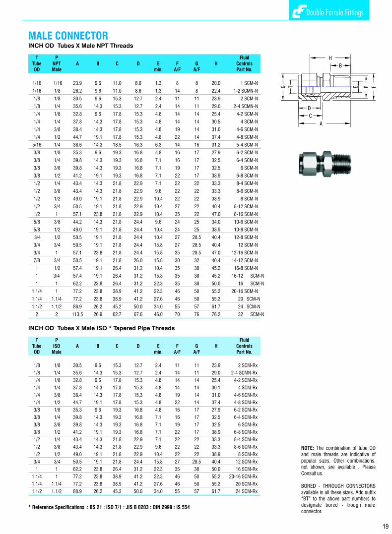
Double Ferrule Fittings Double Ferrule Fittings
MALE CONNECTORINCH OD Tubes X Male NPT Threads
T P FluidTube NPT A B C D E F G H ControlsOD Male min. A/F A/F Part No.
1/16 1/16 23.9 9.6 11.0 8.6 1.3 8 8 20.0 1 SCM-N
1/16 1/8 26.2 9.6 11.0 8.6 1.3 14 8 22.4 1-2 SCMN-N
1/8 1/8 30.5 9.6 15.3 12.7 2.4 11 11 23.9 2 SCM-N
1/8 1/4 35.6 14.3 15.3 12.7 2.4 14 11 29.0 2-4 SCMN-N
1/4 1/8 32.8 9.6 17.8 15.3 4.8 14 14 25.4 4-2 SCM-N
1/4 1/4 37.8 14.3 17.8 15.3 4.8 14 14 30.5 4 SCM-N
1/4 3/8 38.4 14.3 17.8 15.3 4.8 19 14 31.0 4-6 SCM-N
1/4 1/2 44.7 19.1 17.8 15.3 4.8 22 14 37.4 4-8 SCM-N
5/16 1/4 38.6 14.3 18.5 16.3 6.3 14 16 31.2 5-4 SCM-N
3/8 1/8 35.3 9.6 19.3 16.8 4.8 16 17 27.9 6-2 SCM-N
3/8 1/4 39.8 14.3 19.3 16.8 7.1 16 17 32.5 6-4 SCM-N
3/8 3/8 39.8 14.3 19.3 16.8 7.1 19 17 32.5 6 SCM-N
3/8 1/2 41.2 19.1 19.3 16.8 7.1 22 17 38.9 6-8 SCM-N
1/2 1/4 43.4 14.3 21.8 22.9 7.1 22 22 33.3 8-4 SCM-N
1/2 3/8 43.4 14.3 21.8 22.9 9.6 22 22 33.3 8-6 SCM-N
1/2 1/2 49.0 19.1 21.8 22.9 10.4 22 22 38.9 8 SCM-N
1/2 3/4 50.5 19.1 21.8 22.9 10.4 27 22 40.4 8-12 SCM-N
1/2 1 57.1 23.8 21.8 22.9 10.4 35 22 47.0 8-16 SCM-N
5/8 3/8 44.2 14.3 21.8 24.4 9.6 24 25 34.0 10-6 SCM-N
5/8 1/2 49.0 19.1 21.8 24.4 10.4 24 25 38.9 10-8 SCM-N
3/4 1/2 50.5 19.1 21.8 24.4 10.4 27 28.5 40.4 12-8 SCM-N
3/4 3/4 50.5 19.1 21.8 24.4 15.8 27 28.5 40.4 12 SCM-N
3/4 1 57.1 23.8 21.8 24.4 15.8 35 28.5 47.0 12-16 SCM-N
7/8 3/4 50.5 19.1 21.8 26.0 15.8 30 32 40.4 14-12 SCM-N
1 1/2 57.4 19.1 26.4 31.2 10.4 35 38 45.2 16-8 SCM-N
1 3/4 57.4 19.1 26.4 31.2 15.8 35 38 45.2 16-12 SCM-N
1 1 62.2 23.8 26.4 31.2 22.3 35 38 50.0 16 SCM-N
1.1/4 1 77.2 23.8 38.9 41.2 22.3 46 50 55.2 20-16 SCM-N
1.1/4 1.1/4 77.2 23.8 38.9 41.2 27.6 46 50 55.2 20 SCM-N
1.1/2 1.1/2 88.9 26.2 45.2 50.0 34.0 55 57 61.7 24 SCM-N
2 2 113.5 26.9 62.7 67.6 46.0 70 76 76.2 32 SCM-N
INCH OD Tubes X Male ISO * Tapered Pipe Threads
T P FluidTube ISO A B C D E F G H ControlsOD Male min. A/F A/F Part No.
1/8 1/8 30.5 9.6 15.3 12.7 2.4 11 11 23.9 2 SCM-Rx
1/8 1/4 35.6 14.3 15.3 12.7 2.4 14 11 29.0 2-4 SCMN-Rx
1/4 1/8 32.8 9.6 17.8 15.3 4.8 14 14 25.4 4-2 SCM-Rx
1/4 1/4 37.8 14.3 17.8 15.3 4.8 14 14 30.1 4 SCM-Rx
1/4 3/8 38.4 14.3 17.8 15.3 4.8 19 14 31.0 4-6 SCM-Rx
1/4 1/2 44.7 19.1 17.8 15.3 4.8 22 14 37.4 4-8 SCM-Rx
3/8 1/8 35.3 9.6 19.3 16.8 4.8 16 17 27.9 6-2 SCM-Rx
3/8 1/4 39.8 14.3 19.3 16.8 7.1 16 17 32.5 6-4 SCM-Rx
3/8 3/8 39.8 14.3 19.3 16.8 7.1 19 17 32.5 6 SCM-Rx
3/8 1/2 41.2 19.1 19.3 16.8 7.1 22 17 38.9 6-8 SCM-Rx
1/2 1/4 43.4 14.3 21.8 22.9 7.1 22 22 33.3 8-4 SCM-Rx
1/2 3/8 43.4 14.3 21.8 22.9 9.6 22 22 33.3 8-6 SCM-Rx
1/2 1/2 49.0 19.1 21.8 22.9 10.4 22 22 38.9 8 SCM-Rx
3/4 3/4 50.5 19.1 21.8 24.4 15.8 27 28.5 40.4 12 SCM-Rx
1 1 62.2 23.8 26.4 31.2 22.3 35 38 50.0 16 SCM-Rx
1.1/4 1 77.2 23.8 38.9 41.2 22.3 46 50 55.2 20-16 SCM-Rx
1.1/4 1.1/4 77.2 23.8 38.9 41.2 27.6 46 50 55.2 20 SCM-Rx
1.1/2 1.1/2 88.9 26.2 45.2 50.0 34.0 55 57 61.7 24 SCM-Rx
* Reference Specifications : BS 21 : ISO 7/1 : JIS B 0203 : DIN 2999 : IS 554
FEMALE CONNECTORINCH OD Tubes x Female NPT Threads
T P FluidTube NPT A B C D E F G H ControlsOD Female min. A/F A/F Part No.
1/16 1/16 23.6 9.9 11.0 8.6 1.3 11 8 19.8 1 SCF-N
1/16 18 24.4 10.4 11.0 8.6 1.3 14 8 20.6 1-2 SCF-N
1/8 1/8 28.7 10.4 15.3 12.7 2.4 14 11 22.1 2 SCF-N
1/8 1/4 33.6 15.0 15.3 12.7 2.4 19 11 26.9 2-4 SCF-N
1/4 1/8 31.2 9.9 17.8 15.3 4.8 14 14 23.9 4-2 SCF-N
1/4 1/4 35.8 15.0 17.8 15.3 4.8 19 14 28.5 4 SCF-N
1/4 3/8 37.6 15.0 17.8 15.3 4.8 22 14 30.2 4-6 SCF-N
1/4 1/2 42.4 19.8 17.8 15.3 4.8 27 14 35.0 4-8 SCF-N
5/16 1/8 32.0 10.4 18.5 16.3 6.3 14 16 24.6 5-2 SCF-N
5/16 1/4 36.8 15.0 18.5 16.3 6.3 19 16 29.5 5-4 SCF-N
3/8 1/8 32.8 10.4 19.3 16.8 7.1 16 17 25.4 6-2 SCF-N
3/8 1/4 37.6 15.0 19.3 16.8 7.1 19 17 30.2 6-4 SCF-N
3/8 3/8 39.1 15.0 19.3 16.8 7.1 22 17 31.8 6 SCF-N
3/8 1/2 43.9 19.8 19.3 16.8 7.1 27 17 36.6 6-8 SCF-N
1/2 1/4 40.4 15.0 21.8 22.9 10.4 22 22 30.2 8-4 SCF-N
1/2 3/8 41.9 15.0 21.8 22.9 10.4 22 22 30.2 8-6 SCF-N
1/2 1/2 46.7 19.8 21.8 22.9 10.4 27 22 36.6 8 SCF-N
1/2 3/4 48.3 20.6 21.8 22.9 10.4 32 22 38.1 8-12 SCF-N
5/8 3/8 41.9 15.0 21.8 24.4 12.7 24 25 31.8 10-6 SCF-N
5/8 1/2 46.7 19.8 21.8 24.4 12.7 27 25 36.6 10-8 SCF-N
3/4 1/2 46.7 19.8 21.8 24.4 15.8 27 28.5 36.6 12-8 SCF-N
3/4 3/4 48.3 20.6 21.8 24.4 15.8 35 28.5 38.1 12 SCF-N
7/8 3/4 49.8 20.6 21.8 25.9 18.3 35 32 39.6 14-12 SCF-N
1 3/4 53.4 20.6 26.4 31.2 22.3 35 38 41.2 16-12 SCF-N
1 1 62.3 25.4 26.4 31.2 22.3 41 38 50.0 16 SCF-N
1.1/4 1.1/4 74.6 25.4 38.9 41.2 27.6 55 50 52.6 20 SCF-N
1.1/2 1.1/2 83.3 27.6 45.2 50.0 34.0 60 60 56.2 24 SCF-N
INCH OD Tubes x Female ISO* Tapered Pipe Threads
T P Fluid
Tube ISO A B C D E F G H ControlsOD Female min. A/F A/F Part No.
1/16 1/16 23.6 9.9 11.0 8.6 1.3 11 8 19.8 1 SCF-Rx
1/8 1/8 28.7 10.4 15.3 12.7 2.4 14 11 22.1 2 SCF-Rx
1/8 1/4 33.6 15.0 15.3 12.7 2.4 19 11 26.9 2-4 SCF-Rx
1/4 1/8 31.2 9.9 17.8 15.3 4.8 14 14 23.9 4-2 SCF-Rx
1/4 1/4 35.8 15.0 17.8 15.3 4.8 19 14 28.5 4 SCF-Rx
1/4 3/8 37.6 15.0 17.8 15.3 4.8 22 14 30.2 4-6 SCF-Rx
1/4 1/2 42.4 19.8 17.8 15.3 4.8 27 14 35.0 4-8 SCF-Rx
3/8 1/4 37.6 15.0 19.3 16.8 7.1 19 17 30.2 6-4 SCF-Rx
3/8 3/8 39.1 15.0 19.3 16.8 7.1 22 17 31.8 6 SCF-Rx
3/8 1/2 43.9 19.8 19.3 16.8 7.1 27 17 36.6 6-8 SCF-Rx
1/2 1/4 40.4 15.0 21.8 22.9 10.4 22 22 40.4 8-4 SCF-Rx
1/2 3/8 41.9 15.0 21.8 22.9 10.4 22 22 30.2 8-6 SCF-Rx
1/2 1/2 46.7 19.8 21.8 22.9 10.4 27 22 31.8 8 SCF-Rx
3/4 1/2 46.7 19.8 21.8 24.4 15.8 27 28.5 36.6 12-8 SCF-Rx
3/4 3/4 48.3 20.6 21.8 24.4 15.8 35 28.5 38.1 12 SCF-Rx
1 3/4 53.4 20.6 26.4 31.2 22.3 35 38 41.2 16-12 SCF-Rx
1 1 62.3 25.4 26.4 31.2 22.3 41 38 50.0 16 SCF-Rx
1.1/4 1.1/4 74.6 25.4 38.9 41.2 27.6 55 50 52.6 20 SCF-Rx
1.1/2 1.1/2 83.3 27.6 45.2 50.0 34.0 60 60 56.2 24 SCF-Rx
* Reference Specifications : BS 21: ISO 7/1 : JIS B 0203 : DIN 2999 : IS 554
* Female connectors with Parallel ISO Female Threads to BS:2779; ISO 228/1; JIS B6202; DIN 259 are also Available. Their Dimensions are as same as ISO. Tapered Pipe Threads above. Please consult us.
34 19
NOTE: The combination of tube OD and male threads are indicative of popular sizes. Other combinations, not shown, are available . Please Consult us.
BORED - THROUGH CONNECTORS available in all these sizes. Add suffix “BT” to the above part numbers to designate bored - trough male connector.
NOTE: The combinations shown above are representative of various possibilities. Other combinations not shown are also available. Please consult us.

Double Ferrule Fittings Double Ferrule Fittings
POSITIONABLE MALE RUN TEE INCH OD Tubes x SAE/MS *Straight threads
T S Fluid Tube SAE/MS A Ax B C D E F Fx G H Hx Hy U O Ring ControlsOD Male min. A/F A/F A/F Part No. Part No.
1/4 7/16-20 57.0 28.5 9.9 17.8 15.3 4.8 14 14 14 49.5 21.0 28.5 16.5 4 OPU 4 STRsw-U
3/8 9/16-18 64.3 32.0 11.2 19.3 16.8 7.1 16 17 17 56.9 24.6 32.3 20.0 6 OPU 6 STRsw-U
1/2 3/4-16 75.4 37.6 12.7 21.8 22.9 10.4 22 22 22 65.2 27.4 37.8 25.6 8 OPU 8 STRsw-U
3/4 11/16-12 90.2 41.4 16.8 21.8 24.4 15.8 27 32 28.5 80.0 31.2 48.8 36.6 12 OPU 12 STRsw-U
1 15/16-12 104.1 50.5 16.8 26.4 31.2 22.3 35 35 38 92.0 38.4 53.6 44.0 16 OPU 16 STRsw-U
1.1/4 15/8-12 126.0 67.8 16.8 38.9 41.2 27.6 46 50 50 103.9 45.7 58.2 54.9 20 OPU 20 STRsw-U
1.1/2 17/8-12 138.4 78.0 16.8 45.2 50.0 34.0 50 55 60 111.2 50.8 60.4 62.5 24 OPU 24 STRsw-U
METRIC OD Tubes x SAE/MS *Straight threads
T S Fluid Tube SAE/MS A Ax B C D E F Fx G H Hx Hy U O Ring ControlsOD Male min. A/F A/F A/F Part No. Part No.
6 7/16-20 57.0 28.5 9.9 17.7 15.3 4.8 14 14 14 49.5 21.0 28.5 16.5 4 OPU STRsw-6-U
10 9/16-18 64.3 32.0 11.2 19.5 17.2 7.1 16 17 17 56.9 24.6 32.3 20.0 6 OPU STRsw-10-U
12 3/4-16 75.4 37.6 12.7 22.0 22.8 10.4 22 22 22 65.2 27.4 37.8 25.6 8 OPU STRsw-12-U
20 11/16-12 90.2 41.4 16.8 22.0 26.0 15.8 27 32 28.5 80.0 31.2 48.8 36.6 12 OPU STRsw-20-U
25 15/16-12 104.1 50.5 16.8 26.5 31.3 22.3 35 35 38 92.0 38.4 53.6 44.0 16 OPU STRsw-25-U
2 15/8-12 126.0 67.8 16.8 41.6 42.0 27.6 46 50 50 103.9 45.7 58.2 54.9 20 OPU STRsw-32-U
38 17/8-12 138.4 78.0 16.8 47.6 49.4 34.0 50 55 60 111.2 50.8 60.4 62.5 24 OPU STRsw-38-U
INCH OD Tubes x SAE/MS *Straight threads
T S Fluid Tube SAE/MS A Ax B C D E F Fx G H Hx Hy U O Ring ControlsOD Male min. A/F A/F A/F Part No. Part No.
1/4 7/16-20 57.0 28.5 9.9 17.8 15.3 4.8 14 14 14 42.0 21.0 28.5 16.5 4 OPU 4 STBsw-U
3/8 9/16-18 64.0 32.0 11.2 19.3 16.8 7.1 16 17 17 49.2 24.6 32.3 20.0 6 OPU 6 STBsw-U
1/2 3/4-16 75.2 37.6 12.7 21.8 22.9 10.4 22 22 22 54.8 27.4 37.8 25.6 8 OPU 8 STBsw-U
3/4 11/16-12 82.8 41.4 16.8 21.8 24 15.8 27 32 28.5 62.4 31.2 48.8 36.6 12 OPU12 STBsw-U
1 15/16-12 101.0 50.5 16.8 26.4 31.2 22.3 35 35 38 76.8 38.4 53.6 44.0 16 OPU16 STBsw-U
1.1/4 15/8-12 135.6 68 16.8 38.9 41.2 27.6 46 50 50 91.4 46 58 55 20 OPU20 STBsw-U
1.1/2 17/8-12 156.0 78.0 16.8 45.2 50.0 34.0 50 55 60 101.6 51 60 63 24 OPU24 STBsw-U
METRIC OD Tubes x SAE/MS *Straight threads T S Fluid Tube SAE/MS A Ax B C D E F Fx G H Hx Hy U O Ring ControlsOD Male min. A/F A/F A/F Part No. Part No.
6 7/16-20 57.0 28.5 9.9 17.7 15.3 4.8 14 14 14 42.0 21.0 28.5 16.5 4 OPU STBsw-6-U
10 9/16-18 64.0 32.0 11.2 19.5 17.2 7.1 16 17 17 49.2 24.6 32.3 20.0 6 OPU STBsw-10-U
12 3/ -16 75.2 37.6 12.7 22.0 22.8 10.4 22 22 22 54.8 27.4 37.8 25.6 8 OPU STBsw-12-U
20 11/16-12 82.8 41.4 16.8 22.0 26.0 15.8 27 32 28.5 62.4 31.2 48.8 36.6 12 OPUSTBsw-20-U
25 15/16-12 101.0 50.5 16.8 26.5 31.3 22.3 35 35 38 76.8 38.4 53.6 44.0 16 OPUSTBsw-25-U
32 15/8-12 135.6 68 16.8 41.6 42.0 27.6 46 50 50 91.4 46 58 55 20 OPUSTBsw-32-U
38 17/8-12 156.0 78.0 16.8 47.6 49.4 34.0 50 55 60 101.6 51 60 63 24 OPUSTBsw-38-U
POSITIONABLE MALE BRANCH TEE
METRIC OD Tubes x Male NPT Threads
T P Fluid Tube NPT A B C D E F G H ControlsOD Male min. A/F A/F Part No.
3 1/8 30.5 9.6 15.3 12.9 2.4 11 11 23.9 SCM 3-2N
3 1/4 35.6 14.3 15.3 12.9 2.4 14 11 29.0 SCM 3-4N
6 1/8 32.8 9.6 17.7 15.3 4.8 14 14 25.4 SCM 6-2N
6 1/4 37.9 14.3 17.7 15.3 4.8 14 14 30.5 SCM 6-4N
6 3/8 38.4 14.3 17.7 15.3 4.8 19 14 31.0 SCM 6-N
6 1/2 44.7 19.1 17.7 15.3 4.8 22 14 37.3 SCM 6-8N
8 1/8 34.2 9.6 18.6 16.2 4.8 14 16 26.7 SCM 8-2N
8 1/4 38.7 14.3 18.6 16.2 6.3 14 16 31.2 SCM 8-4N
8 3/8 39.3 14.3 18.6 16.2 6.3 19 16 31.8 SCM 8-6N
8 1/2 45.6 19.1 18.6 16.2 6.3 22 16 38.1 SCM 8-N
10 1/8 36.3 9.6 19.5 17.2 4.8 17 19 28.7 SCM 10-2N
10 1/4 40.9 14.3 19.5 17.2 7.9 19 19 33.3 SCM 10-4N
10 3/8 40.9 14.3 19.5 17.2 7.9 19 19 33.3 SCM 10-6N
10 1/2 46.5 19.1 19.5 17.2 7.9 22 19 38.9 SCM 10-8N
12 1/4 43.4 14.3 22.0 22.8 7.1 22 22 33.3 SCM 12-4N
12 3/8 43.4 14.3 22.0 22.8 9.5 22 22 33.3 SCM 12-6N
12 1/2 49.0 19.1 22.0 22.8 9.5 22 22 38.9 SCM 12-8N
12 3/4 50.5 19.1 22.0 22.8 9.5 27 22 40.4 SCM 12-N
12 1 57.1 23.8 22.0 22.8 9.5 35 22 47.0 SCM 12-16N
14 1/4 44.1 14.3 22.0 24.4 7.1 24 25 34.0 SCM 14-4N
14 3/8 44.1 14.3 22.0 24.4 9.5 24 25 34.0 SCM 14-6N
14 1/2 49.0 19.1 22.0 24.4 11.1 24 25 38.9 SCM 14-8N
15 1/2 49.0 19.1 22.0 24.4 11.9 24 25 38.9 SCM 15 8N
16 3/8 44.1 14.3 22.0 24.4 9.5 24 25 34.0 SCM 16-6N
16 1/2 49.0 19.1 22.0 24.4 11.9 24 25 38.9 SCM 16-8N
16 3/4 50.5 19.1 22.0 24.4 12.7 27 25 40.4 SCM 16-12N
18 1/2 50.5 19.1 22.0 24.4 11.9 27 30 40.4 SCM 18-8N
18 3/4 50.5 19.1 22.0 24.4 15.1 27 30 40.4 SCM 18-12N
20 1/2 52.3 19.1 22.0 26.0 11.9 30 32 42.2 SCM 20-8N
20 3/4 52.3 19.1 22.0 26.0 15.9 30 32 42.2 SCM 20-12N
22 3/4 52.3 19.1 22.0 26.0 15.9 30 32 42.2 SCM 22-12N
22 1 57.1 23.8 22.0 26.0 18.3 35 32 47.0 SCM 22 16N
25 1/2 57.5 19.1 26.5 31.3 11.9 35 38 45.2 SCM 25- 8N
25 3/4 57.5 19.1 26.5 31.3 15.8 35 38 45.2 SCM 25-12N
25 1 62.3 23.8 26.5 31.3 21.8 35 38 50.0 SCM 25-16N
28 1 72.4 23.8 36.6 36.6 21.8 41 46 51.6 SCM 28-16N
28 1.1/4 73.1 23.8 36.6 36.6 21.8 46 46 52.3 SCM 28-20N
30 1.1/4 77.2 23.8 39.2 39.6 26.2 46 50 55.6 SCM 30-20N
32 1.1/4 79.6 23.8 41.6 42.0 28.6 46 50 56.6 SCM 32-20N
38 1.1/2 96.6 26.2 47.9 49.4 33.7 55 57 64.0 SCM 38-24N
MALE CONNECTOR
20 33
* Reference Specifications : SAE Screw Thread standard conforms to American standard B1.1. Unified screw threads.
Bored-Through Fittings for Thermocouples
To order, add BT to the desired Fluid Controls Male Connector Part Number : 8 SCM - N. BTExample : Bored Through Connection 1/2” OD x 1/2” NPT (M) with 1/2” OD through bore has part number.

Double Ferrule Fittings Double Ferrule Fittings
MALE CONNECTORMETRIC OD Tubes x Male ISO* Tapered Pipe Thread
T P Fluid Tube ISO A B C D E F G H ControlsOD Male min. A/F A/F Part No.
3 1/8 30.5 9.6 15.3 12.9 2.4 11 11 23.9 SCM 3-2 Rx
3 1/4 35.6 14.3 15.3 12.9 2.4 14 11 29.0 SCM 3-4 Rx
6 1/8 32.8 9.6 17.7 15.3 4.8 14 14 25.4 SCM 6-2 Rx
6 1/4 37.9 14.3 17.7 15.3 4.8 14 14 30.5 SCM 6-4 Rx
6 3/8 38.4 14.3 17.7 15.3 4.8 19 14 31.0 SCM 6 Rx
6 1/2 44.7 19.1 17.7 15.3 4.8 22 14 37.3 SCM 6-8 Rx
8 1/8 34.2 9.6 18.6 16.2 4.8 14 16 26.7 SCM 8-2 Rx
8 1/4 38.7 14.3 18.6 16.2 6.3 14 16 31.2 SCM 8-4 Rx
8 3/8 39.3 14.3 18.6 16.2 6.3 19 16 31.8 SCM 8-6 Rx
8 1/2 45.6 19.1 18.6 16.2 6.3 22 16 38.1 SCM 8 Rx
10 1/8 36.3 9.6 19.5 17.2 4.8 17 19 28.7 SCM 10-2 Rx
10 1/4 40.9 14.3 19.5 17.2 7.9 19 19 33.3 SCM 10-4 Rx
10 3/8 40.9 14.3 19.5 17.2 7.9 19 19 33.3 SCM 10-6 Rx
10 1/2 46.5 19.1 19.5 17.2 7.9 22 19 38.9 SCM 10-8 Rx
12 1/4 43.4 14.3 22.0 22.8 7.1 22 22 33.3 SCM 12-4 Rx
12 3/8 43.4 14.3 22.0 22.8 9.5 22 22 33.3 SCM 12-6 Rx
12 1/2 49.0 19.1 22.0 22.8 9.5 22 22 38.9 SCM 12-8 Rx
12 3/4 50.5 19.1 22.0 22.8 9.5 27 22 40.4 SCM 12 Rx
12 1 57.1 23.8 22.0 22.8 9.5 35 22 47.0 SCM 12-16 Rx
14 3/8 44.1 14.3 22.0 24.4 9.5 24 25 34.0 SCM 14-6 Rx
14 1/2 49.0 19.1 22.0 24.4 11.1 24 25 38.9 SCM 14-8 Rx
15 1/2 49.0 19.1 22.0 24.4 11.9 24 25 38.9 SCM 15 8 Rx
16 3/8 44.1 14.3 22.0 24.4 9.5 24 25 34.0 SCM 16-6 Rx
16 1/2 49.0 19.1 22.0 24.4 11.9 24 25 38.9 SCM 16-8 Rx
16 3/4 50.5 19.1 22.0 24.4 12.7 27 25 40.4 SCM 16-12 Rx
18 1/2 50.5 19.1 22.0 24.4 11.9 27 30 40.4 SCM 18-8 Rx
18 3/4 50.5 19.1 22.0 24.4 15.1 27 30 40.4 SCM 18-12 Rx
20 1/2 52.3 19.1 22.0 26.0 11.9 30 32 42.2 SCM 20-8 Rx
20 3/4 52.3 19.1 22.0 26.0 15.9 30 32 42.2 SCM 20-12 Rx
22 3/4 52.3 19.1 22.0 26.0 15.9 30 32 42.2 SCM 22-12 Rx
22 1 57.1 23.8 22.0 26.0 18.3 35 32 47.0 SCM 22 16 Rx
25 1/2 57.5 19.1 26.5 31.3 11.9 35 38 45.2 SCM 25- 8 Rx
25 3/4 57.5 19.1 26.5 31.3 15.8 35 38 45.2 SCM 25-12 Rx
25 1 62.3 23.8 26.5 31.3 21.8 35 38 50.0 SCM 25-16 Rx
28 1 72.4 23.8 36.6 36.6 21.8 41 46 51.6 SCM 28-16 Rx
28 1.1/4 73.1 23.8 36.6 36.6 21.8 46 46 52.3 SCM 28-20 Rx
30 1.1/4 77.2 23.8 39.2 39.6 26.2 46 50 55.6 SCM30-20 RX
32 1.1/4 79.6 23.8 41.6 42.0 28.6 46 50 56.6 SCM32-20 Rx
38 1.1/2 96.6 26.2 47.9 49.4 33.7 55 57 64.0 SCM 38-24 Rx
* Reference Specifications : BS 21: ISO 7/1 : JIS B 0203 : DIN 2999 : IS 554
32
POSITIONABLE MALE RUN TEE INCH OD Tubes X Male ISO* Parallel Threads
T P FluidTube ISO A Ax B C D E F Fx G H Hx Hy U O Ring ControlsOD Male min. A/F A/F A/F Part No. Part No.
1/4 1/8 53.4 27.0 8.2 17.8 15.3 4.0 14 14 14 46.0 19.6 26.4 17.3 2 Opn 4-2 STRsw-R 1/4 1/4 61.3 29.0 9.2 17.8 15.3 4.8 16 19 14 53.9 21.6 32.3 22.9 4 Opn 4 STRsw-R
3/8 1/4 62.8 30.5 9.2 19.3 16.8 5.8 16 19 17 55.5 23.2 32.3 22.9 4 Opn 6-4 STRsw-R
1/2 3/8 73.0 36.0 9.4 21.8 22.9 7.8 22 22 22 62.9 25.9 37.0 26.4 6 Opn 8-6 STRsw-R
1/2 1/2 81.5 38.1 13.0 21.8 24.4 10.4 24 27 22 71.3 27.9 43.4 32.0 8 Opn 8 STRsw-R
5/8 1/2 81.5 38.1 13.0 21.8 24.4 10.4 24 27 25 71.3 27.9 43.4 32.0 8 Opn 10-8 STRsw-R
3/4 1/2 85.1 39.9 13.0 21.8 24.4 10.4 27 27 28.5 74.9 29.7 45.2 32.0 8 Opn 12-8 STRsw-R
3/4 3/4 88.7 39.9 13.0 21.8 24.4 15.8 27 35 28.5 78.5 29.7 48.8 41.2 12 Opn 12 STRsw-R
1 1 102.6 49.0 14.0 26.4 31.2 19.8 35 41 38 90.4 36.8 53.6 48.5 16 Opn 16 STRSw-R
METRIC OD Tubes X Male ISO* Parallel Threads
T P FluidTube ISO A Ax B C D E F Fx G H Hx Hy U O Ring ControlsOD Male min. A/F A/F A/F Part No. Part No.
6 1/8 53.4 27.0 8.1 17.7 15.3 4.0 14 14 14 46.0 19.6 26.4 17.3 2 Opn STR sw 6-2R
6 1/4 61.3 29.0 9.1 17.7 15.3 4.8 16 19 14 53.9 21.6 32.3 22.9 4 Opn STR sw 6-4R
8 1/8 56.2 28.8 8.1 18.6 16.2 4.0 14 14 16 48.7 21.3 27.4 17.3 2 Opn STR sw 8-2R
8 1/4 62.1 29.9 9.1 18.6 16.2 5.9 16 19 16 54.6 22.4 32.2 22.9 4 Opn STR sw 8-4R
10 1/4 68.5 33.5 9.1 19.5 17.2 5.9 19 19 19 61.9 25.9 35.0 22.9 4 Opn STR sw 10-4R
12 3/8 73.1 36.0 9.4 22.0 22.8 7.9 22 22 22 63.0 25.9 37.1 26.4 6 Opn STR sw 12-6R
12 1/2 81.4 38.0 13.0 22.0 23 9.5 24 27 22 71.3 27.9 43.4 32.0 8 Opn STR sw 12-8R
16 1/2 83.3 38.1 13.0 22.0 24.4 11.9 27 27 28.5 74.9 29.7 45.2 32.0 8 Opn STR sw 16-8R
22 3/4 93.4 44.6 13.0 22.0 26.0 15.8 27 35 28.5 83.3 34.5 48.8 41.2 12 OpnSTR sw 22-12R
25 3/4 102.3 49.0 13.0 26.5 31.3 15.8 35 35 38 90.1 36.8 53.3 41.2 12 OpnSTR sw 25-12R
25 1 102.6 49.0 14.0 26.5 31.3 21.8 35 41 38 90.4 36.8 53.6 48.5 16 OpnSTR sw 25-16R
Inch OD Tubes X Male ISO* Parallel Thread
T P FluidTube ISO A Ax B C D E F Fx G H Hx Hy U O Ring ControlsOD Male min. A/F A/F A/F Part No. Part No.
1/4 1/8 53.4 27.0 8.2 17.8 15.3 4.0 14 14 14 46.0 19.6 26.4 17.3 2 OPN 4-2 STBsw-R
1/4 1/4 61.3 29.0 9.2 17.8 15.3 4.8 16 19 14 53.9 21.6 32.3 22.9 4 OPN 4 STBsw-R
3/8 1/4 62.8 30.5 9.2 19.3 16.8 5.8 16 19 17 55.5 23.2 32.3 22.9 4 OPN 6-4 STBsw-R
1/2 3/8 73.0 36.0 9.4 21.8 22.9 7.8 22 22 22 62.9 25.9 37.0 26.4 6 OPN 8-6 STBsw-R
1/2 1/2 81.5 38.1 13.0 21.8 24.4 10.4 24 27 22 71.3 27.9 43.4 32.0 8 OPN 8 STBsw-R
5/8 1/2 81.5 38.1 13.0 21.8 24.4 10.4 24 27 25 71.3 27.9 43.4 32.0 8 OPN 10-8 STBsw-R
3/4 1/2 85.1 39.9 13.0 21.8 24.4 10.4 27 27 28.5 74.9 29.7 45.2 32.0 8 OPN 12-8 STBsw-R
3/4 3/4 88.7 39.9 13.0 21.8 24.4 15.8 27 35 28.5 78.5 29.7 48.8 41.2 12 OPN 12 STBsw-R
1 1 102.6 49.0 14.0 26.4 31.2 19.8 35 41 38 90.4 36.8 53.6 48.5 16 OPN 16 STBsw-R
Metric OD Tubes X Male ISO* Parallel Threads
T P FluidTube ISO A AX B C D E F FX G H HX HY U O Ring ControlsOD MALE min. A/F A/F A/F Part No. Part No.
6 1/8 53.4 27.0 8.1 17.7 15.3 4.0 14 14 14 46.0 19.6 26.4 17.3 2 OPN STBsw 6-2R6 1/4 61.3 29.0 9.1 17.7 15.3 4.8 16 19 14 53.9 21.6 32.3 22.9 4 OPN STBsw 6-4R
8 1/8 56.2 28.8 8.1 18.6 16.2 4.0 14 14 16 48.7 21.3 27.4 17.3 2 OPN STBsw 8-2R
8 1/4 62.1 29.9 9.1 18.6 16.2 5.9 16 19 16 54.6 22.4 32.2 22.9 4 OPN STBsw 8-4R
10 1/4 68.5 33.5 9.1 19.5 17.2 5.9 19 19 19 61.9 25.9 35.0 22.9 4 OPN STBsw 10-4R
12 3/8 73.1 36.0 9.4 22.0 22.8 7.9 22 22 22 63.0 25.9 37.1 26.4 6 OPN STBsw 12-6R
12 1/2 81.4 38.0 13.0 22.0 23 9.5 24 27 22 71.3 27.9 43.4 32.0 8 OPN STBsw 12-8R
16 1/2 83.3 38.1 13.0 22.0 24.4 11.9 27 27 28.5 74.9 29.7 45.2 32.0 8 OPN STBsw 16-8R
22 3/4 93.4 44.6 13.0 22.0 26.0 15.8 27 35 28.5 83.3 34.5 48.8 41.2 12 OPN STBsw 22-12R
25 3/4 102.3 49.0 13.0 26.5 31.3 15.8 35 35 38 90.1 36.8 53.3 41.2 12 OPN STBsw 25-12R25 1 102.6 49.0 14.0 26.5 31.3 21.8 35 41 38 90.4 36.8 53.6 48.5 16 OPN STBsw 25-16R
* Reference Specifications : BS 2779 : ISO 228/1 : JIS B0202 : DIN-ISO 228/1
POSITIONABLE BRANCH TEE
* Reference Specifications : BS 2779 : ISO 228/1 : JIS B0202 : DIN-ISO 228/1
21
Bored-Through Fittings for Thermocouples
To order, add BT to the desired Fluid Controls Male Connector Part Number : 8 SCM - Rx. BTExample : Bored Through Connection 1/2” OD x 1/2” ISO Tapered Male Pipe Thread 1/2” OD through bore has part number.

Double Ferrule Fittings Double Ferrule Fittings
INCH OD Tubes x Male NPT Threads
T P FluidTube NPT A Ax B C D E F G H Hx Hy ControlsOD Male min. A/F A/F Part No.
1/8 1/8 47.2 23.6 9.6 15.3 12.7 2.4 11 11 34.0 17.0 17.8 2 STBM-N
1/8 1/4 49.2 24.6 14.3 15.3 12.7 2.4 14 11 36.0 18.0 23.4 2-4 STBM-N
1/4 1/8 53.8 26.9 9.6 17.8 5.3 4.8 14 14 39.2 19.6 18.8 4-2 STBM-N
1/4 1/4 53.8 26.9 14.3 17.8 15.3 4.8 14 14 39.2 19.6 23.4 4 STBM-N
1/4 3/8 59.4 29.7 14.3 17.8 15.3 4.8 19 14 44.8 22.4 26.2 4-6 STBM-N
1/4 1/2 63.6 31.8 19.1 17.8 15.3 4.8 22 14 44.8 24.4 33.0 4-8 STBM-N
3/8 1/4 61.0 30.5 14.3 19.3 16.8 7.1 17 17 46.2 23.1 25.4 6-4 STBM-N
3/8 3/8 62.4 31.2 14.3 19.3 16.8 7.1 19 17 47.8 23.9 26.2 6 STBM-N
3/8 1/2 66.0 33.0 19.1 19.3 16.8 7.1 22 17 51.8 25.9 33.0 6-8 STBM-N
1/2 1/4 72.0 36.0 14.3 21.8 22.9 4.8 22 22 51.8 25.9 28.2 8-4 STBM-N
1/2 3/8 72.0 36.0 14.3 21.8 22.9 9.6 22 22 51.8 25.9 28.2 8-6 STBM-N
1/2 1/2 72.0 36.0 19.1 21.8 22.9 10.4 22 22 51.8 25.9 33.0 8 STBM-N
5/8 1/2 76.2 38.1 19.1 21.8 24.4 11.9 22 25 55.8 27.9 35.0 10-8 STBM-N
3/4 1/2 79.8 39.9 19.1 21.8 24.4 11.9 27 29 59.4 29.7 36.8 12-8 STBM-N
3/4 3/4 79.8 39.9 19.1 21.8 24.4 15.8 27 29 59.4 29.7 36.8 12 STBM-N
1 3/4 98.0 49.0 19.1 26.4 31 15.8 35 38 73.6 36.8 41.6 16-12 STBM-N
1 1 98.0 49.0 23.8 26.4 31 22.3 35 38 73.6 36.8 46.5 16 STBM-N
1.1/4 1.1/4 133.0 66.5 23.8 38.8 41.1 27.6 46 50 89.0 44.5 47.6 20 STBM-N
1.1/2 1.1/2 156.0 78.0 26.2 45.2 50.0 34.0 55 57 101.6 50.8 60.4 24 STBM-N
METRIC OD Tubes x Male NPT Threads
T P FluidTube NPT A Ax B C D E F G H Hx Hy ControlsOD Male min. A/F A/F Part No.
3 1/8 47.2 23.6 9.6 15.3 12.9 2.4 11 11 34.0 17.0 17.8 STBM 3-2N
3 1/4 49.2 24.6 14.3 15.3 12.9 2.4 14 11 36.0 18.0 23.4 STBM 3-4N
6 1/8 54.0 27.0 9.6 17.7 15.3 4.8 14 14 39.2 19.6 18.8 STBM 6-2N
6 1/4 54.0 27.0 14.3 17.7 15.3 4.8 14 14 39.2 19.6 23.4 STBM 6-4N
6 3/8 59.6 29.8 14.3 17.7 15.3 4.8 19 14 44.8 22.4 26.2 STBM 6-N
8 1/4 57.6 28.8 14.3 18.6 16.2 6.3 14 16 42.6 21.3 24.4 STBM 8-4N
8 3/8 61.2 30.6 14.3 18.6 16.2 6.3 19 16 46.2 23.1 26.2 STBM 8-6N
8 1/2 65.2 32.6 19.1 18.6 16.2 6.3 22 16 50.2 25.1 33.0 STBM 8-N
10 1/4 63.0 31.5 14.3 19.5 17.2 7.1 17 19 47.8 23.9 26.2 STBM 10-4N
10 3/8 63.0 31.5 14.3 19.5 17.2 7.9 19 19 47.8 23.9 26.2 STBM 10-6N
10 1/2 67.0 33.5 19.1 19.5 17.2 7.9 22 19 51.8 25.9 33.0 STBM 10-8N
12 1/4 72.0 36.0 14.3 22.0 22.8 7.1 22 22 51.8 25.9 26.2 STBM 12-4N
12 3/8 72.0 36.0 14.3 22.0 22.8 9.5 22 22 51.8 25.9 28.2 STBM 12-6N
12 1/2 72.0 36.0 19.1 22.0 22.8 9.5 22 22 51.8 25.9 33.0 STBM 12-8N
16 1/2 76.0 38.0 19.1 22.0 24 11.9 24 25 55.8 27.9 35.1 STBM 16-8N
25 3/4 98.2 49.1 19.1 26.5 31.3 15.8 35 38 73.6 36.8 41.7 STBM 25-12N
25 1 98.2 49.1 23.8 26.5 31.3 21.8 35 38 73.6 36.8 46.5 STBM 25-16N
30 1.1/4 139.8 66.9 23.8 39.2 39.6 26.2 45 50 96.6 48.3 53.1 STBM 30-20N
32 1.1/4 144.6 72.3 23.8 41.6 42.0 27.6 45 50 98.6 49.3 53.1 STBM 32-20N
38 1.1/2 168.0 84.0 26.2 47.9 50.0 33.7 55 57 112.8 56.4 60.4 STBM 38-24N
MALE BRANCH TEE
NOTE: The combination of tube OD and male threads are indicative of popular sizes. Other combinations, not shown, are available . Please Consult us.
MALE CONNECTORINCH OD Tubes x Male ISO* Parallel Threads - RP
T P FluidTube ISO A B C D E F Fd G H ControlsOD Male min. A/F A/F Part No.
1/8 1/8 30.0 7.1 15.3 12.7 2.4 14 13.7 11 23.4 2 SCM-Rp
1/8 1/4 35.3 11.2 15.3 12.7 2.4 19 18.0 11 28.7 2-4 SCMN-Rp
1/4 1/8 32.3 7.1 17.8 15.3 4.8 14 13.7 14 24.9 4-2 SCM-Rp
1/4 1/4 37.6 11.2 17.8 15.3 4.8 19 18.0 14 30.2 4 SCM-Rp
1/4 3/8 38.9 11.2 17.8 15.3 4.8 22 21.8 14 31.5 4-6 SCM-Rp
1/4 1/2 44.7 14.2 17.8 15.3 4.8 27 26.0 14 37.4 4-8 SCM-Rp
3/8 1/4 39.2 11.2 19.3 16.8 5.8 19 18.0 17 31.8 6-4 SCM-Rp
3/8 3/8 40.4 11.2 19.3 16.8 7.1 22 21.8 17 33.0 6 SCM-Rp
3/8 1/2 46.3 14.2 19.3 16.8 7.1 27 26.0 17 38.9 6-8 SCM-Rp
1/2 1/4 42.7 11.2 21.8 22.9 5.8 22 18.0 22 32.5 8-4 SCM-Rp
1/2 3/8 43.2 11.2 21.8 22.9 7.9 22 21.8 22 33.0 8-6 SCM-Rp
1/2 1/2 49.0 14.2 21.8 22.9 10.4 27 26.0 22 38.9 8 SCM-Rp
1/2 3/4 52.8 15.7 21.8 22.9 10.4 35 32.0 22 42.7 8-12 SCM-Rp
3/4 1/2 49.0 14.2 21.8 24.4 11.9 27 26.0 28.5 38.9 12-8 SCM-Rp
3/4 3/4 52.8 15.7 21.8 24.4 15.8 35 32.0 28.5 42.7 12 SCM-Rp
3/4 1 55.4 18.3 21.8 24.4 15.8 41 39.0 28.5 45.6 12-16 SCM-Rp
1 1/2 55.9 14.2 26.4 31.2 11.9 35 26.0 38 43.7 16-8 SCM-Rp
1 3/4 57.5 15.7 26.4 31.2 15.8 35 32.0 38 45.2 16-12 SCM-Rp
1 1 60.0 18.3 26.4 31.2 19.8 41 39.0 38 47.8 16 SCM-Rp
1.1/4 1.1/4 78.9 19.8 38.9 41.2 25.0 50 49.0 50 55.9 20 SCM-Rp
1.1/2 1.1/2 90.8 22.1 45.2 50.0 31.8 60 54.7 57 63.2 24 SCM-Rp
METRIC OD Tubes x Male ISO* Parallel Threads - RP
T P Fluid
Tube ISO A B C D E F Fd G H ControlsOD Male min. A/F A/F Part No.
3 1/8 30.0 7.1 15.3 12.9 2.4 14 13.8 11 23.4 SCM 3-2Rp
3 1/4 35.3 11.2 15.3 12.9 2.4 19 18.0 11 28.7 SCM 3-4Rp
6 1/8 32.3 7.1 17.7 15.3 4.8 14 13.8 14 24.9 SCM 6-2Rp
6 1/4 37.6 11.2 17.7 15.3 4.8 19 18.0 14 30.2 SCM 6-4Rp
6 3/8 38.9 11.2 17.7 15.3 4.8 22 21.8 14 31.5 SCM 6-Rp
6 1/2 44.7 14.2 17.7 15.3 4.8 27 26.0 14 37.3 SCM 6-8Rp
8 1/8 33.2 7.1 18.6 16.2 4.0 14 13.8 16 25.7 SCM 8-2Rp
8 1/4 38.5 11.2 18.6 16.2 6.4 19 18.0 16 31.0 SCM 8-4Rp
8 3/8 39.8 11.2 18.6 16.2 6.4 22 21.8 16 32.3 SCM 8-6Rp
8 1/2 45.6 14.2 18.6 16.2 6.4 27 26.0 16 38.1 SCM 8-Rp
10 1/4 39.4 11.2 19.5 17.2 5.9 19 18.0 19 31.8 SCM 10-4Rp
10 3/8 40.6 11.2 19.5 17.2 7.6 22 21.8 19 33.0 SCM 10-6Rp
10 1/2 46.5 14.2 19.5 17.2 7.9 27 26.0 19 38.9 SCM 10-8Rp
12 1/4 42.6 11.2 22.0 22.8 5.9 22 18.0 22 32.5 SCM 12-4Rp
12 3/8 43.1 11.2 22.0 22.8 7.9 22 21.8 22 33.0 SCM 12-6Rp
12 1/2 49.0 14.2 22.0 22.8 9.5 27 26.0 22 38.9 SCM 12-8Rp
12 3/4 52.8 15.7 22.0 22.8 9.5 35 32.0 22 42.7 SCM 12Rp
16 3/8 43.9 11.2 22.0 24.4 7.9 24 21.8 25 33.8 SCM 16-6Rp
16 1/2 49.0 14.2 22.0 24.4 11.9 27 26.0 25 38.9 SCM 16-8Rp
20 1/2 50.5 14.2 22.0 26.0 11.9 30 26.0 28.5 40.4 SCM 20-8Rp
20 3/4 52.3 15.7 22.0 26.0 15.9 35 32.0 28.5 42.7 SCM 22-12Rp
22 3/4 52.3 15.7 22.0 26.0 15.9 35 32.0 32 42.7 SCM 20-16Rp
22 1 55.3 18.3 22.0 26.0 18.3 41 39.0 32 45.2 SCM 25-12Rp
25 3/4 57.5 15.7 26.5 31.3 15.9 35 32.0 38 45.2 SCM 20-16Rp
25 1 60.1 18.3 26.5 31.3 19.8 41 39.0 38 47.8 SCM 20-12Rp
28 1 70.1 18.3 36.6 36.6 19.8 41 39.0 46 49.3 SCM 28-16Rp
30 1.1/4 76.5 19.8 39.2 39.6 25.0 50 49.0 50 54.9 SCM 30-20Rp
32 1.1/4 78.9 19.8 41.6 42.0 25.0 50 49.0 50 55.9 SCM 32-20Rp
38 1.1/2 90.8 22.1 47.9 49.4 31.8 55 54.7 57 63.2 SCM 38-24Rp
* Reference Specifications : BS 2779 : ISO 228/1 : JIS B 0202 : DIN-ISO 228/1
22 31
NOTE: The ISO parallel Thread System RP shown on this page does not create pressure tight seal against the threads. The seal is made by metal to metal contact against the female part. A sof t metal (usually annealed copper) gasket between the fitting and the part face.
BORED - THROUGH FITTINGS FOR THERMOCOUPLE ARE AVAILABLE WITH ISO P ARALLEL MALE THREADS. Add suffix “BT” to the above part numbers above.

Double Ferrule Fittings Double Ferrule Fittings
30
MALE CONNECTORINCH OD Tubes x Male ISO* Parallel Threads - RS
T P FluidTube ISO A B C D E F Fd G H ControlsOD Male min. A/F A/F Part No..
1/8 1/8 30.0 7.1 15.3 12.7 2.4 14 13.7 11 23.4 2 SCM-Rs
1/8 1/4 35.3 11.2 15.3 12.7 2.4 19 18.0 11 28.7 2-4 SCMN-Rs
1/4 1/8 32.3 7.1 17.8 15.3 4.8 14 13.7 14 24.9 4-2 SCM-Rs
1/4 1/4 37.6 11.2 17.8 15.3 4.8 19 18.0 14 30.2 4 SCM-Rs
1/4 3/8 38.9 11.2 17.8 15.3 4.8 22 21.8 14 31.5 4-6 SCM-Rs
1/4 1/2 44.7 14.2 17.8 15.3 4.8 27 26.0 14 37.4 4-8 SCM-Rs
3/8 1/4 39.2 11.2 19.3 16.8 5.8 19 18.0 17 31.8 6-4 SCM-Rs
3/8 3/8 40.4 11.2 19.3 16.8 7.1 22 21.8 17 33.0 6 SCM-Rs
3/8 1/2 46.3 14.2 19.3 16.8 7.1 27 26.0 17 38.9 6-8 SCM-Rs
1/2 1/4 42.7 11.2 21.8 22.9 5.8 22 18.0 22 32.5 8-4 SCM-Rs
1/2 3/8 43.2 11.2 21.8 22.9 7.9 22 21.8 22 33.0 8-6 SCM-Rs
1/2 1/2 49.0 14.2 21.8 22.9 10.4 27 26.0 22 38.9 8 SCM-Rs
1/2 3/4 52.8 15.7 21.8 22.9 10.4 35 32.0 22 42.7 8-12 SCM-Rs
3/4 1/2 49.0 14.2 21.8 24.4 11.9 27 26.0 28.5 38.9 12-8 SCM-Rs
3/4 3/4 52.8 15.7 21.8 24.4 15.8 35 32.0 28.5 42.7 12 SCM-Rs
3/4 1 55.4 18.3 21.8 24.4 15.8 41 39.0 28.5 45.6 12-16 SCM-Rs
1 1/2 55.9 14.2 26.4 31.2 11.9 35 26.0 38 43.7 16-8 SCM-Rs
1 3/4 57.5 15.7 26.4 31.2 15.8 35 32.0 38 45.2 16-12 SCM-Rs
1 1 60.0 18.3 26.4 31.2 19.8 41 39.0 38 47.8 16 SCM-Rs
1.1/4 1.1/4 78.9 19.8 38.9 41.2 25.0 50 49.0 50 55.9 20 SCM-Rs
1.1/2 1.1/2 90.8 22.1 45.2 50.0 31.8 60 54.7 57 63.2 24 SCM-Rs
METRIC OD Tube x Male ISO* Parallel Threads - RS
T P FluidTube ISO A B C D E F Fd G H ControlsOD Male min. A/F A/F Part No.
3 1/8 30.0 7.1 15.3 12.9 2.4 14 13.8 11 23.4 SCM 3-2 Rs
3 1/4 35.3 11.2 15.3 12.9 2.4 19 18.0 11 28.7 SCM 3-4 Rs
6 1/8 32.3 7.1 17.7 15.3 4.8 14 13.8 14 24.9 SCM 6-2 Rs
6 1/4 37.6 11.2 17.7 15.3 4.8 19 18.0 14 30.2 SCM 6-4 Rs
6 3/8 38.9 11.2 17.7 15.3 4.8 22 21.8 14 31.5 SCM 6- Rs
6 1/2 44.7 14.2 17.7 15.3 4.8 27 26.0 14 37.3 SCM 6-8 Rs
8 1/8 33.2 7.1 18.6 16.2 4.0 14 13.8 16 25.7 SCM 8-2 Rs
8 1/4 38.5 11.2 18.6 16.2 6.4 19 18.0 16 31.0 SCM 8-4 Rs
8 3/8 39.8 11.2 18.6 16.2 6.4 22 21.8 16 32.3 SCM 8-6 Rs
8 1/2 45.6 14.2 18.6 16.2 6.4 27 26.0 16 38.1 SCM 8 Rs
10 1/4 39.4 11.2 19.5 17.2 5.9 19 18.0 19 31.8 SCM 10-4 Rs
10 3/8 40.6 11.2 19.5 17.2 7.6 22 21.8 19 33.0 SCM 10-6 Rs
10 1/2 46.5 14.2 19.5 17.2 7.9 27 26.0 19 38.9 SCM 10-8 Rs
12 1/4 42.6 11.2 22.0 22.8 5.9 22 18.0 22 32.5 SCM 12-4 Rs
12 3/8 43.1 11.2 22.0 22.8 7.9 22 21.8 22 33.0 SCM 12-6 Rs
12 1/2 49.0 14.2 22.0 22.8 9.5 27 26.0 22 38.9 SCM 12-8 Rs
12 3/4 52.8 15.7 22.0 22.8 9.5 35 32.0 22 42.7 SCM 12 Rs
16 3/8 43.9 11.2 22.0 24.4 7.9 24 21.8 25 33.8 SCM 16-6 Rs
16 1/2 49.0 14.2 22.0 24.4 11.9 27 26.0 25 38.9 SCM 16-8 Rs
20 1/2 50.5 14.2 22.0 26.0 11.9 30 26.0 28.5 40.4 SCM 20-8 Rs
20 3/4 52.3 15.7 22.0 26.0 15.9 35 32.0 28.5 42.7 SCM 22-12 Rs
22 3/4 52.3 15.7 22.0 26.0 15.9 35 32.0 32 42.7 SCM 20-16 Rs
22 1 55.3 18.3 22.0 26.0 18.3 41 39.0 32 45.2 SCM 25-12 Rs
25 3/4 57.5 15.7 26.5 31.3 15.9 35 32.0 38 45.2 SCM 20-16 Rs
25 1 60.1 18.3 26.5 31.3 19.8 41 39.0 38 47.8 SCM 20-12 Rs
28 1 70.1 18.3 36.6 36.6 19.8 41 39.0 46 49.3 SCM 28-16 Rs
30 1.1/4 76.5 19.8 39.2 39.6 25.0 50 49.0 50 54.9 SCM 30-20 Rs
32 1.1/4 78.9 19.8 41.6 42.0 25.0 50 49.0 50 55.9 SCM 32-20 Rs
38 1.1/2 90.8 22.1 47.9 49.4 31.8 55 54.7 57 63.2 SCM 38-24 Rs
* Reference Specifications : BS 2779 : ISO 228/1 : JIS B0202 : DIN-ISO 228/1
INCH OD Tubes X Male NPT Threads
T P FluidTube NPT A Ax B C D E F G H Hx Hy ControlsOD Male min. A/F A/F Part No.
1/8 1/8 41.4 23.6 9.6 15.3 12.7 2.4 11 11 34.8 17.0 17.8 2 STRM-N
1/8 1/4 48.0 24.6 14.3 15.3 12.7 2.4 14 11 41.4 18.0 23.4 2-4 STRM-N
1/4 1/8 45.7 26.9 9.6 17.8 15.3 4.8 14 14 38.4 19.6 18.8 4-2 STRM-N
1/4 1/4 50.3 26.9 14.3 17.8 15.3 4.8 14 14 43 19.6 23.4 4 STRM-N
1/4 3/8 55.9 29.7 14.3 17.8 15.3 4.8 19 14 48.8 22.4 26.2 4-6 STRM-N
1/4 1/2 64.8 31.8 19.1 17.8 15.3 4.8 22 14 57.4 24.4 33.0 4-8 STRM-N
3/8 1/4 55.9 30.5 14.3 19.3 16.8 7.1 17 17 48.5 23.1 25.4 6-4 STRM-N
3/8 3/8 57.4 31.2 14.3 19.3 16.8 7.1 19 17 50.1 23.9 26.2 6 STRM-N
3/8 1/2 66.0 33.0 19.1 19.3 16.8 7.1 22 17 58.9 25.9 33.0 6-8 STRM-N
1/2 1/4 64.2 36.0 14.3 21.8 22.9 4.8 22 22 54.1 25.9 28.2 8-4 STRM-N
1/2 3/8 64.2 36.0 14.3 21.8 22.9 9.6 22 22 54.1 25.9 28.2 8-6 STRM-N
1/2 1/2 69.0 36.0 19.1 21.8 22.9 10.4 22 22 58.9 25.9 33.0 8 STRM-N
5/8 1/2 73.1 38.1 19.1 21.8 24.4 11.9 22 25 62.9 27.9 35.0 10-8 STRM-N
3/4 1/2 76.7 39.9 19.1 21.8 24.4 11.9 27 29 66.5 29.7 36.8 12-8 STRM-N
3/4 3/4 76.7 39.9 19.1 21.8 24.4 15.8 27 29 66.5 29.7 36.8 12 STRM-N
1 3/4 90.6 49.0 19.1 26.4 31.2 15.8 35 38 78.4 36.8 41.6 16-12 STRM N
1 1 95.5 49.0 23.8 26.4 31.2 22.3 35 38 83.3 36.8 46.5 16 STRM-N
1.1/4 1.1/4 114.1 66.5 23.8 38.8 41.1 27.6 46 50 92.1 44.5 47.6 20 STRM-N
1.1/2 1.1/2 138.4 78.0 26.2 45.2 50.0 34.0 55 57 111.2 50.8 60.4 24 STRM-N
METRIC OD Tubes X Male NPT Threads
T P Fluid
Tube NPT A Ax B C D E F G H Hx Hy ControlsOD Male min. A/F A/F Part No.
3 1/8 41.4 23.6 9.6 15.3 12.9 2.4 11 11 34.8 17.0 17.8 STRM 3-2N
3 1/4 48.0 24.6 14.3 15.3 12.9 2.4 14 11 41.4 18.0 23.4 STRM 3-4N
6 1/8 45.8 27.0 9.6 17.7 15.3 4.8 14 14 38.9 19.6 18.8 STRM 6-2N
6 1/4 50.4 27.0 14.3 17.7 15.3 4.8 14 14 43.0 19.6 23.4 STRM 6-4N
6 3/8 56.0 29.8 14.3 17.7 15.3 4.8 19 14 48.6 22.4 26.2 STRM 6-N
8 1/4 53.2 28.8 14.3 18.6 16.2 6.3 14 16 45.7 21.3 24.4 STRM 8-4N
8 3/8 56.8 30.6 14.3 18.6 16.2 6.3 19 16 49.3 23.1 26.2 STRM 8-6N
8 1/2 65.6 32.6 19.1 18.6 16.2 6.3 22 16 58.1 25.1 33.0 STRM 8-N
10 1/4 57.7 31.5 14.3 19.5 17.2 7.1 17 19 50.1 23.9 26.2 STRM 10-4N
10 3/8 57.7 31.5 14.3 19.5 17.2 7.9 19 19 50.1 23.9 26.2 STRM 10-6N
10 1/2 66.5 33.5 19.1 19.5 17.2 7.9 22 19 58.9 25.9 33.0 STRM 10-8N
12 1/4 62.2 36.0 14.3 22.0 22.8 7.1 22 22 52.1 25.9 26.2 STRM 12-4N
12 3/8 62.2 36.0 14.3 22.0 22.8 9.5 22 22 52.1 25.9 28.2 STRM 12-6N
12 1/2 69.0 36.0 19.1 22.0 22.8 9.5 22 22 58.9 25.9 33.0 STRM 12-8N
16 1/2 73.1 38.0 19.1 22.0 24 11.9 24 25 64.0 27.9 35.1 STRM 16-8N
25 3/4 90.8 49.1 19.1 26.5 31.3 15.8 35 38 78.5 36.8 41.7 STRM 25-12N
25 1 95.6 49.1 23.8 26.5 31.3 21.8 35 38 83.3 36.8 46.5 STRM 25-16N
30 1.1/4 120.0 66.9 23.8 39.2 39.6 26.2 45 50 101.4 48.3 53.1 STRM 30-20N
32 1.1/4 125.4 72.3 23.8 41.6 42.0 27.6 45 50 102.4 49.3 53.1 STRM 32-20N
38 1.1/2 144.4 84.0 26.2 47.9 50.0 33.7 55 57 116.8 56.4 60.4 STRM 38-24N
MALE RUN TEE
NOTE: The ISO Parallel Thread system shown on this page does not create pressure tight seal against the threads. The seal is made by a bounded washer seal between the fitting and female part face. A soft metal (Copper) Gasket way also be used.
NOTE: The combination of tube OD and male threads are indicative of popular sizes. Other combinations, not shown, are available . Please Consult us.
23

Double Ferrule Fittings Double Ferrule Fittings Double Ferrule Fittings Double Ferrule Fittings
O SEAL MALE CONNECTOR INCH OD Tubes x Male ISO* Parallel Threads
T P Fluid Tube ISO A B C D E F Fd G H O Ring ControlsOD Male min. A/F A/F Part No. Part No.
1/8 1/8 32.8 7.1 15.3 12.7 2.4 19 18.8 11 26.2 2 OPN 2 SCO-R
1/4 1/8 35.0 7.1 17.8 15.3 4.8 19 18.8 14 27.7 2 OPN 4-2 SCO-R
1/4 1/4 40.0 11.2 17.8 15.3 7.1 24 23.6 14 32.6 4OPN 4 SCO-R
3/8 1/4 41.5 11.2 19.3 16.8 7.1 24 23.6 17 34.1 4 OPN 6-4 SCO-R
3/8 3/8 42.2 11.2 19.3 16.8 7.1 30 29.8 17 34.8 6 OPN 6 SCO-R
3/8 1/2 47.7 14.2 19.3 16.8 9.6 32 31.8 17 40.3 8 OPN 6-8 SCO-R
1/2 3/8 44.5 10.4 21.8 22.9 10.4 30 29.8 22 34.4 6 OPN 8-6 SCO-R
1/2 1/2 50.4 14.2 21.8 22.9 11.9 32 31.8 22 40.3 8 OPN 8 SCO-R
5/8 1/2 50.4 14.2 21.8 24.4 11.9 32 31.8 22 40.3 8 OPN 10-8 SCO-R
3/4 1/2 50.4 14.2 21.8 24.4 15.8 32 31.8 28.5 40.3 8 OPN 12-8 SCO-R
3/4 3/4 53.5 15.7 21.8 24.4 15.8 38 37.8 28.5 43.4 12 OPN 12 SCO-R
1 3/4 58.2 15.7 26.4 31.2 22.3 38 37.8 38 46.0 12OPN 16-12 SCO-R
1 1 62.2 18.3 26.4 31.2 27.6 45 44.0 38 50.0 16 OPN 16 SCO-R
1.1/4 1.1/4 77.6 12.0 38.9 41.4 27.6 55 54.0 50 55.6 20 OPN 20 SCO-R
1.1/2 1.1/2 88.9 12.0 45.2 50.0 34.0 60 58.0 57 61.7 24 OPN 24 SCO-R
METRIC OD Tubes x Male ISO* Parallel Threads
T P Fluid Tube ISO A B C D E F Fd G H O Ring ControlsOD Male min. A/F A/F Part No. Part No.
3 1/8 32.8 7.1 15.3 12.9 2.4 19 18.8 11 26.2 2 OPN SCO 3-2 R
3 1/4 37.6 11.2 15.3 12.9 2.4 24 23.8 11 31.0 4 OPN SCO 3-4 R
6 1/4 40.1 11.2 17.7 15.3 4.8 24 23.8 14 32.7 4 OPN SCO 6-4 R
6 3/8 40.8 11.2 17.7 15.3 4.8 30 29.8 14 33.4 6 OPN SCO 6 R
8 1/4 40.9 11.2 18.6 16.2 6.3 24 23.8 16 33.4 4 OPN SCO 8-4 R
10 1/4 41.0 11.2 19.5 17.2 7.1 24 23.8 17 33.4 4 OPN SCO 10-4 R
10 3/8 42.6 11.2 19.5 17.2 7.1 30 29.8 17 35.0 6 OPN SCO 10-6 R
10 1/2 48.0 14.2 19.5 17.2 7.9 32 31.8 17 40.4 8 OPN SCO 10-8 R
12 1/4 44.3 11.2 22.0 22.8 7.1 24 21.8 22 34.2 4 OPN SCO 12-4 R
12 3/8 45.1 11.2 22.0 22.8 7.9 30 29.8 22 34.0 6 OPN SCO 12-6 R
12 1/2 50.5 14.3 22.0 22.8 9.5 32 31.8 22 40.4 8 OPN SCO 12-8 R
16 1/2 50.5 14.3 22.0 24.4 11.9 32 31.8 25 40.4 8 OPN SCO 16-8 R
20 3/4 55.1 15.7 22.0 26.0 15.8 38 37.0 32 45.0 12 OPN SCO 20-2 R
25 3/4 58.1 15.7 26.5 31.3 15.8 38 37.0 38 45.8 12 OPN SCO 25-2 R
25 1 62.3 18.3 26.5 31.3 19.8 45 44.0 38 50.0 16 OPN SCO 25-16 R
* Reference Specifications : BS 2779 : ISO 228/1 : JIS B0202 : DIN-ISO 228/1
INCH OD Tube x Male Straight Threads - UNF
T S Fluid Tube Thread A B C D E F Fd G H O Ring ControlsOD Male min. A/F A/F Part No. Part No.
1/8 5/16 -24 32.8 8.6 15.3 12.7 2.4 14 13.8 11 26.2 1 OPU 2 SCO-U
1/4 7/16 -20 38.4 10.4 17.8 15.3 4.8 19 18.8 14 31.0 2 OPU 4 SCO-U
5/16 1/2 -20 40.6 11.2 18.5 16.3 6.3 22 21.8 16 33.3 3 OPU 5 SCO-U
3/8 9/16 -18 42.4 12.0 19.3 16.8 7.1 24 23.6 17 35.0 4 OPU 6 SCO-U
1/2 3/4 -16 46.0 12.0 21.8 22.9 10.4 28.5 28.0 22 35.8 6 OPU 8 SCO-U
3/4 11/16 -12 52.4 14.3 21.8 24.4 15.8 38 37.8 28.5 42.2 12 OPU 12 SCO-U
1 15/16-12 58.2 14.3 26.4 31.2 22.3 45 44.0 38 46.0 16 OPU 16 SCO-U
1.1/4 15/8-12 76.2 18.3 38.9 41.4 27.6 55 54.0 50 54.1 20 OPU 20 SCO-U
1.1/2 17/8 -12 86.6 19.8 45.2 50.0 34.0 60 58.0 57 59.4 24 OPU 24 SCO-U
POSITIONABLE MALE ELBOWINCH OD Tubes X Male ISO* Parallel Threads
T P FluidTube ISO Ax B C D E F Fx G Hx Hy U O Ring ControlsOD Male min. A/F A/F A/F Part No. Part No.
1/4 1/8 27.0 8.2 17.8 15.3 4.0 14 14 14 19.6 26.4 17.3 2 Opn 4-2 SEsw-R
1/4 1/4 29.0 9.2 17.8 15.3 4.8 16 19 14 21.6 32.3 22.9 4 Opn 4 SEsw-R
3/8 1/4 30.5 9.2 19.3 16.8 5.8 16 19 17 23.2 32.3 22.9 4 Opn 6-4 SEsw-R
3/8 3/8 33.0 9.2 19.3 16.8 7.1 22 22 17 25.9 37.0 26.4 6 Opn 6 SEsw-R
1/2 1/4 36.0 9.2 21.8 22.9 5.8 22 19 22 25.9 35.0 22.9 4 Opn 8-4 SEsw-R
1/2 3/8 36.0 9.4 21.8 22.9 7.8 22 22 22 25.9 37.0 26.4 6 Opn 8-6 SEsw-R
1/2 1/2 38.1 13.0 21.8 24.4 10.4 24 27 22 27.9 43.4 32.0 8 Opn 8 SEsw-R
5/8 1/2 38.1 13.0 21.8 24.4 10.4 24 27 25 27.9 43.4 32.0 8 Opn 10-8 SEsw-R
3/4 1/2 39.9 13.0 21.8 24.4 10.4 27 27 28.5 29.7 45.2 32.0 8 Opn 12-8 SEsw-R
3/4 3/4 39.9 13.0 21.8 24.4 15.8 27 35 28.5 29.7 48.8 41.2 12 Opn 12 SEsw-R
1 3/4 49.0 13.0 26.4 31.2 15.8 35 35 38 36.8 53.3 41.2 12 Opn 16-12 SEsw-R
1 1 49.0 14.0 26.4 31.2 19.8 35 41 38 36.8 53.6 48.5 16 Opn 16 SEsw-R
METRIC OD Tubes X Male ISO* Parallel Threads
T P FluidTube ISO Ax B C D E F Fx G Hx Hy U O Ring ControlsOD Male min. A/F A/F A/F Part No. Part No.
6 1/8 27.0 8.1 17.7 15.3 4.0 14 14 14 19.6 26.4 17.3 2 Opn SEsw 6-2R
6 1/4 29.0 9.1 17.7 15.3 4.8 16 19 14 21.6 32.3 22.9 4 Opn SEsw 6-4R
8 1/8 28.8 8.1 18.6 16.2 4.0 14 14 16 21.3 27.4 17.3 2 Opn SEsw 8-2R
8 1/4 29.9 9.1 18.6 16.2 5.9 16 19 16 22.4 32.2 22.9 4 Opn SEsw 8-4R
10 1/4 33.5 9.1 19.5 17.2 5.9 19 19 19 25.9 35.0 22.9 4 Opn SEsw 10-4R
10 3/8 33.5 9.4 19.5 17.2 7.9 19 22 19 25.9 37.1 26.4 6 Opn SEsw 10-6R
12 3/8 36.0 9.4 22.0 22.8 7.9 22 22 22 25.9 37.1 26.4 6 Opn SEsw 12-6R
12 1/2 38.0 13.0 22.0 22.8 9.5 24 27 22 27.9 43.4 32.0 8 Opn SEsw 12-8R
12 3/4 39.8 13.0 22.0 22.8 9.5 27 35 22 29.7 48.8 41.1 12 Opn SEsw 12R
16 1/2 38.1 13.0 22.0 24.4 11.9 27 27 28.5 29.7 45.2 32.0 8 Opn SEsw 16-8R
22 3/4 44.6 13.0 22.0 26.0 15.8 27 35 28.5 34.5 48.8 41.2 12 Opn SEsw 22-12R
25 3/4 49.0 13.0 26.5 31.3 15.8 35 35 38 36.8 53.3 41.2 12 Opn SEsw 25-12R
25 1 49.0 14.0 26.5 31.3 21.8 35 41 38 36.8 53.6 48.5 16 Opn Sesw 25-16R
* Reference Specifications : BS 2779 : ISO 228/1 : JIS B0202 : DIN-ISO 228/1
INCH OD Tube x SAE/MS Straight Threads
T P FluidTube ISO Ax B C D E F Fx G Hx Hy U O Ring ControlsOD Male min. A/F A/F Part No. Part No.
1/4 7/16-20 28.5 9.9 17.8 15.3 4.8 14 14 14 21.0 28.5 16.5 4 OPU 4 SEsw-U
1/4 9/16-18 30.5 11.2 17.8 15.3 4.8 16 17 14 23.1 32.3 20.0 6 OPU 4-6 SEsw-U
3/8 9/16-18 32.0 11.2 19.3 16.8 7.1 16 17 17 24.6 32.3 20.0 6 OPU 6 SEsw-U
3/8 3/4-16 34.8 12.7 19.3 16.8 7.1 22 22 17 27.4 37.8 25.6 8 OPU 6-8 SEsw-U
1/2 3/4-16 37.6 12.7 21.8 22.9 10.4 22 22 22 27.4 37.8 25.6 8 OPU 8 SEsw-U
5/8 7/16-14 39.6 14.3 21.8 24.4 12.7 24 25 25 29.5 43.4 29.5 10 OPU 10 SEsw-U
3/4 11/16-12 41.4 16.8 21.8 24.4 15.8 27 32 28.5 31.2 48.8 36.6 12 OPU 12 SEsw-U
7/8 11/16-12 43.2 16.8 21.8 25.9 18.3 30 32 32 33 50.5 40.4 14 OPU 14 SEsw-U
1 15/16-12 50.5 16.8 26.4 31.2 22.3 35 35 38 38.4 53.6 44.0 16 OPU 16 SEsw-U
1.1/4 15/8-12 67.8 16.8 38.9 41.2 27.6 46 50 50 45.7 58.2 54.9 20 OPU 20 SEsw-U
1.1/2 17/8-12 78.0 16.8 45.2 50.0 34.0 50 55 60 50.8 60.4 62.5 24 OPU 24 SEsw-U
2924
* Reference Specifications : SAE Screw Thread standard conforms to American standard B1.1. Unified screw threads.
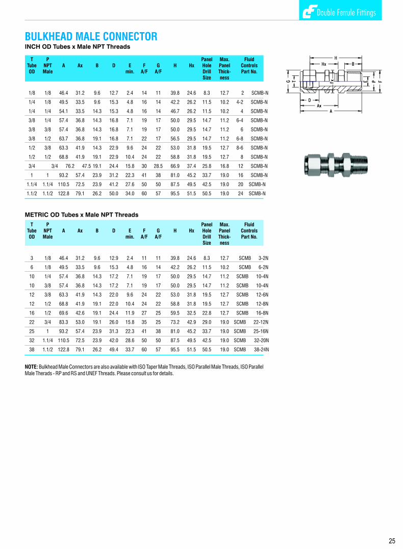
Double Ferrule Fittings Double Ferrule Fittings
BULKHEAD MALE CONNECTORINCH OD Tubes x Male NPT Threads
T P Panel Max. FluidTube NPT A Ax B D E F G H Hx Hole Panel ControlsOD Male min. A/F A/F Drill Thick- Part No.
Size ness
1/8 1/8 46.4 31.2 9.6 12.7 2.4 14 11 39.8 24.6 8.3 12.7 2 SCMB-N
1/4 1/8 49.5 33.5 9.6 15.3 4.8 16 14 42.2 26.2 11.5 10.2 4-2 SCMB-N
1/4 1/4 54.1 33.5 14.3 15.3 4.8 16 14 46.7 26.2 11.5 10.2 4 SCMB-N
3/8 1/4 57.4 36.8 14.3 16.8 7.1 19 17 50.0 29.5 14.7 11.2 6-4 SCMB-N
3/8 3/8 57.4 36.8 14.3 16.8 7.1 19 17 50.0 29.5 14.7 11.2 6 SCMB-N
3/8 1/2 63.7 36.8 19.1 16.8 7.1 22 17 56.5 29.5 14.7 11.2 6-8 SCMB-N
1/2 3/8 63.3 41.9 14.3 22.9 9.6 24 22 53.0 31.8 19.5 12.7 8-6 SCMB-N
1/2 1/2 68.8 41.9 19.1 22.9 10.4 24 22 58.8 31.8 19.5 12.7 8 SCMB-N
3/4 3/4 76.2 47.5 19.1 24.4 15.8 30 28.5 66.9 37.4 25.8 16.8 12 SCMB-N
1 1 93.2 57.4 23.9 31.2 22.3 41 38 81.0 45.2 33.7 19.0 16 SCMB-N
1.1/4 1.1/4 110.5 72.5 23.9 41.2 27.6 50 50 87.5 49.5 42.5 19.0 20 SCMB-N
1.1/2 1.1/2 122.8 79.1 26.2 50.0 34.0 60 57 95.5 51.5 50.5 19.0 24 SCMB-N
METRIC OD Tubes x Male NPT Threads
T P Panel Max. FluidTube NPT A Ax B D E F G H Hx Hole Panel ControlsOD Male min. A/F A/F Drill Thick- Part No.
Size ness
3 1/8 46.4 31.2 9.6 12.9 2.4 11 11 39.8 24.6 8.3 12.7 SCMB 3-2N
6 1/8 49.5 33.5 9.6 15.3 4.8 16 14 42.2 26.2 11.5 10.2 SCMB 6-2N
10 1/4 57.4 36.8 14.3 17.2 7.1 19 17 50.0 29.5 14.7 11.2 SCMB 10-4N
10 3/8 57.4 36.8 14.3 17.2 7.1 19 17 50.0 29.5 14.7 11.2 SCMB 10-4N
12 3/8 63.3 41.9 14.3 22.0 9.6 24 22 53.0 31.8 19.5 12.7 SCMB 12-6N
12 1/2 68.8 41.9 19.1 22.0 10.4 24 22 58.8 31.8 19.5 12.7 SCMB 12-8N
16 1/2 69.6 42.6 19.1 24.4 11.9 27 25 59.5 32.5 22.8 12.7 SCMB 16-8N
22 3/4 83.3 53.0 19.1 26.0 15.8 35 25 73.2 42.9 29.0 19.0 SCMB 22-12N
25 1 93.2 57.4 23.9 31.3 22.3 41 38 81.0 45.2 33.7 19.0 SCMB 25-16N
32 1.1/4 110.5 72.5 23.9 42.0 28.6 50 50 87.5 49.5 42.5 19.0 SCMB 32-20N
38 1.1/2 122.8 79.1 26.2 49.4 33.7 60 57 95.5 51.5 50.5 19.0 SCMB 38-24N
NOTE: Bulkhead Male Connectors are also available with ISO Taper Male Threads, ISO Parallel Male Threads, ISO Parallel Male Therads - RP and RS and UNEF Threads. Please consult us for details.
INCH OD Tube x SAE/MS Straight Threads
T P Fluid Tube SAE/MS A B C D E F Fx G Hx Hy U O Ring ControlsOD Male min. A/F A/F A/F Part No. Part No.
1/4 7/16-20 25.7 9.9 17.8 15.3 4.8 14 14 14 18.3 25.6 16.5 4 OPU 4 SEsw/45-U
3/8 9/16-18 27.9 11.2 19.3 16.8 7.1 16 17 17 20.6 28.2 20.0 6 OPU 6 SEsw/45-U
1/2 3/4-16 32.0 12.7 21.8 22.9 10.4 22 22 22 21.8 32.3 25.7 8 OPU 8 SEsw/45-U
3/4 11/16-12 39.9 16.8 21.8 24.4 15.8 27 32 28.5 29.7 47.3 36.6 12 OPU 12 SEsw/45-U
1 15/16-12 47.5 16.8 26.4 31.2 19.8 35 38 38 35.3 50.6 44.0 16 OPU 16 SEsw/45-U
* Reference Specifications : SAE Screw Thread standard conforms to American standard B1.1. Unified screw threads.
45 DEG. POSITIONABLE MALE ELBOW
45 DEG. MALE ELBOW INCH OD Tubes x Male NPT Threads
T P FluidTube NPT A B C D E F G Hx Hy ControlsOD Male min. A/F A/F Part No.
1/4 1/8 24.6 9.6 17.8 15.3 4.8 14 14 17.3 16.5 4-2 SEM/45-N
1/4 1/4 24.6 14.3 17.8 15.3 4.8 14 14 17.3 21.0 4 SEM/45-N
3/8 1/8 27.9 9.6 19.3 16.8 4.8 14 17 20.6 18.3 6-2 SEM/45-N
3/8 1/4 27.9 14.3 19.3 16.8 7.1 17 17 20.6 22.9 6-4 SEM/45-N
3/8 3/8 29.2 14.3 19.3 16.8 7.1 19 17 21.8 24.1 6 SEM/45-N
1/2 3/8 32.0 14.3 21.8 22.9 9.6 22 22 21.8 24.1 8-6 SEM/45-N
1/2 1/2 32.0 19.1 21.8 22.9 10.4 22 22 21.8 29.0 8 SEM/45-N
3/4 3/4 34.0 19.1 21.8 24.4 15.8 27 28.5 23.9 31.8 12 SEM/45-N
1 1 40.4 23.8 26.4 31.2 22.3 35 38 26.2 37.8 16 SEM/45-N
28 25
INCH OD Tube x Male ISO* Parallel Threads
T P Fluid Tube ISO A B C D E F Fx G Hx Hy U O Ring ControlsOD Male min. A/F A/F A/F Part No. Part No.
1/4 1/4 25.7 9.9 17.8 15.3 4.8 14 14 14 18.3 25.6 16.5 4 OPU 4 SEsw/45-R
3/8 3/8 27.9 11.2 19.3 16.8 7.1 16 17 17 20.6 28.2 20.0 6 OPU 6 SEsw/45-R
1/2 1/2 32.0 12.7 21.8 22.9 10.4 22 22 22 21.8 32.3 25.7 8 OPU 8 SEsw/45-R
3/4 3/4 39.9 16.8 21.8 24.4 15.8 27 32 28.5 29.7 47.3 36.6 12 OPU 12 SEsw/45-R
1 1 47.5 16.8 26.4 31.2 19.8 35 38 38 35.3 50.6 44.0 16 OPU 16 SEsw/45-R
* Reference Specifications : BS 2779 : ISO 228/1 : JIS B0202 : DIN-ISO 228/1

Double Ferrule Fittings Double Ferrule Fittings
INCH OD Tubes x Male NPT Thread
T P FluidTube NPT A B C D E F G Hx Hy ControlsOD Male min. A/F A/F Part No.
1/16 1/16 19.0 9.6 10.9 8.6 1.3 11 11 15.3 17.8 1 SEM-N
1/16 1/8 19.0 9.6 10.9 8.6 1.3 11 11 15.3 17.8 1-2 SEM-N
1/8 1/8 23.6 9.6 15.3 12.7 2.4 11 11 17.0 17.8 2 SEM-N
1/8 1/4 24.6 14.3 15.3 12.7 2.4 14 11 18.0 23.4 2-4 SEM-N
1/4 1/8 26.9 9.6 17.8 5.3 4.8 14 14 19.6 18.8 4-2 SEM-N
1/4 1/4 26.9 14.3 17.8 15.3 4.8 14 14 19.6 23.4 4 SEM-N
1/4 3/8 29.7 14.3 17.8 15.3 4.8 19 14 22.4 26.2 4-6 SEM-N
1/4 1/2 31.8 19.1 17.8 15.3 4.8 22 14 24.4 33.0 4-8 SEM-N
5/16 1/4 28.7 9.6 18.5 16.3 6.3 14 16 21.3 24.4 5-4 SEM-N
3/8 1/8 30.5 9.6 19.3 16.8 4.8 14 17 23.1 20.9 6-2 SEM-N
3/8 1/4 30.5 14.3 19.3 16.8 7.1 17 17 23.1 25.4 6-4 SEM-N
3/8 3/8 31.2 14.3 19.3 16.8 7.1 19 17 23.9 26.2 6 SEM-N
3/8 1/2 33.3 19.1 19.3 16.8 7.1 22 17 25.9 33.0 6-8 SEM-N
1/2 1/4 36.0 14.3 21.8 22.9 4.8 22 22 25.9 28.2 8-4 SEM-N
1/2 3/8 36.0 14.3 21.8 22.9 9.6 22 22 25.9 28.2 8-6 SEM-N
1/2 1/2 36.0 19.1 21.8 22.9 10.4 22 22 25.9 33.0 8 SEM-N
1/2 3/4 39.9 19.1 21.8 22.9 10.4 27 22 29.7 36.8 8-12 SEM-N
5/8 1/2 38.1 19.1 21.8 24.4 11.9 24 25 27.9 35.0 10-8 SEM-N
3/4 1/2 39.9 19.1 21.8 24.4 11.9 27 28.5 29.7 36.8 12-8 SEM-N
3/4 3/4 39.9 19.1 21.8 24.4 15.8 27 28.5 29.7 36.8 12 SEM-N
7/8 3/4 44.7 19.1 21.8 25.9 15.8 35 32 34.5 41.6 14-12 SEM-N
1 3/4 49.0 19.1 26.4 31.2 15.8 35 38 36.8 41.6 16-12 SEM-N
1 1 49.0 23.8 26.4 31.2 22.3 35 38 36.8 46.5 16 SEM-N
1.1/4 1.1/4 66.5 23.8 38.8 41.1 27.6 46 50 44.5 47.8 20 SEM-N
1.1/2 1.1/2 78.0 26.2 45.2 50.0 34.0 55 57 50.8 60.4 24 SEM-N
2 2 107.2 26.9 62.7 67.6 46.0 70 76 69.9 70.6 32 SEM-N
INCH OD Tubes x Male ISO* Tapered Pipe Threads
T P FluidTube ISO A B C D E F G Hx Hy ControlsOD Male min. A/F A/F Part No.
1/8 1/8 23.6 9.6 15.3 12.7 2.4 11 11 17.0 17.8 2 SEM-Rx 1/8 1/4 24.6 14.3 15.3 12.7 2.4 14 11 18.0 23.4 2-4 SEM-Rx
1/4 1/8 26.9 9.6 17.8 5.3 4.8 14 14 19.6 18.8 4-2 SEM-Rx
1/4 1/4 26.9 14.3 17.8 15.3 4.8 14 14 19.6 23.4 4 SEM-Rx
1/4 3/8 29.7 14.3 17.8 15.3 4.8 19 14 22.4 26.2 4-6 SEM-Rx
1/4 1/2 31.8 19.1 17.8 15.3 4.8 22 14 24.4 33.0 4-8 SEM-Rx
3/8 1/8 30.5 9.6 19.3 16.8 4.8 14 17 23.1 20.9 6-2 SEM-Rx
3/8 1/4 30.5 14.3 19.3 16.8 7.1 17 17 23.1 25.4 6-4 SEM-Rx
3/8 3/8 31.2 14.3 19.3 16.8 7.1 19 17 23.9 26.2 6 SEM-Rx
3/8 1/2 33.3 19.1 19.3 16.8 7.1 22 17 25.9 33.0 6-8 SEM-Rx
1/2 1/4 36.0 14.3 21.8 22.9 4.8 22 22 25.9 28.2 8-4 SEM-Rx
1/2 3/8 36.0 14.3 21.8 22.9 9.6 22 22 25.9 28.2 8-6 SEM-Rx
1/2 1/2 36.0 19.1 21.8 22.9 10.4 22 22 25.9 33.0 8 SEM-Rx
1/2 3/4 39.9 19.1 21.8 22.9 10.4 27 22 29.7 36.8 8-12 SEM-Rx
3/4 1/2 39.9 19.1 21.8 24.4 11.9 27 28.5 29.7 36.8 12-8 SEM-Rx
3/4 3/4 39.9 19.1 21.8 24.4 15.8 27 28.5 29.7 36.8 12 SEM-Rx
1 3/4 49.0 19.1 26.4 31.2 15.8 35 38 36.8 41.6 16-12 SEM-Rx
1 1 49.0 23.8 26.4 31.2 22.3 35 38 36.8 46.5 16 SEM-Rx
1.1/4 1.1/4 66.5 23.8 38.8 41.1 27.6 46 50 44.5 47.8 20 SEM-Rx
1.1/2 1.1/2 78.0 26.2 45.2 50.0 34.0 55 57 50.8 60.4 24 SEM-Rx
* Reference Specifications : BS 21: ISO 7/1 : JIS B 0203 : DIN 2999 : IS 554
NOTE: The combination of tube OD and male threads are indicative of popular sizes. Other combinations, not shown, are available . Please Consult us.
MALE ELBOW METRIC OD Tubes x Male NPT Threads
T P FluidTube NPT A B C D E F G Hx Hy ControlsOD Male min. A/F A/F Part No.
3 1/8 23.6 9.6 15.3 12.9 2.4 11 11 17.0 17.8 SEM-3-2N
3 1/4 24.6 14.3 15.3 12.9 2.4 14 11 18.0 23.4 SEM-3-4N
6 1/8 27.0 9.6 17.7 15.3 4.8 14 14 19.6 18.8 SEM-6-2N
6 1/4 27.0 14.3 17.7 15.3 4.8 14 14 19.6 23.4 SEM-6-4N
6 3/8 29.8 14.3 17.7 15.3 4.8 19 14 22.4 26.2 SEM-6N
6 1/2 31.8 19.1 17.7 15.3 4.8 22 14 24.4 33.0 SEM-6-8N
8 1/8 28.8 9.6 18.6 16.2 4.8 14 16 21.3 19.8 SEM-8-2N
8 1/4 28.8 14.3 18.6 16.2 6.3 14 16 21.3 24.4 SEM-8-4N
8 3/8 30.6 14.3 18.6 16.2 6.3 19 16 23.1 26.2 SEM-8-6N
8 1/2 32.6 19.1 18.6 16.2 6.3 22 16 25.1 33.0 SEM-8N
10 1/8 31.5 9.6 19.5 17.2 4.8 17 19 23.9 21.6 SEM-10-2N
10 1/4 31.5 14.3 19.5 17.2 7.1 17 19 23.9 26.2 SEM-10-4N
10 3/8 31.5 14.3 19.5 17.2 7.9 19 19 23.9 26.2 SEM-10-6N
10 1/2 33 19.1 19.5 17.2 7.9 22 19 25.9 33.0 SEM-10-8N
12 1/4 36.0 14.3 22.0 22.8 7.1 22 22 25.9 26.2 SEM-12-4N
12 3/8 36.0 14.3 22.0 22.8 9.5 22 22 25.9 38.2 SEM-12-6N
12 1/2 36.0 19.1 22.0 22.8 9.5 22 22 25.9 33.0 SEM-12-8N
12 3/4 39.8 19.1 22.0 22.8 9.5 27 22 29.7 36.8 SEM-12N
15 1/2 38.0 19.1 22.0 24.4 11.9 24 25 27.9 35.1 SEM-15-8N
16 1/2 38.0 19.1 22.0 24.4 11.9 24 25 27.9 35.1 SEM-16-8N
16 3/4 39.8 19.1 22.0 24.4 27.7 27 25 29.7 36.8 SEM-16-12N
18 1/2 39.8 19.1 22.0 24.4 11.9 27 30 29.7 36.8 SEM-18-8N
18 3/4 39.8 19.1 22.0 24.4 15.1 27 30 29.7 36.8 SEM-18-12N
20 1/2 44.6 19.1 22.0 26.0 11.9 35 32 34.5 41.7 SEM-20-8N
20 3/4 44.6 19.1 22.0 26.0 15.9 35 32 34.5 41.7 SEM-20-12N
22 3/4 44.6 19.1 22.0 26.0 15.9 35 32 34.5 41.7 SEM-22-12N
22 1 44.6 23.9 22.0 26.0 18.3 35 32 34.5 46.5 SEM-22-16N
25 3/4 49.1 19.1 26.5 31.3 59.9 35 38 36.8 41.7 SEM-25-12N
25 1 41.1 23.9 26.5 31.3 21.8 35 38 36.8 46.5 SEM-25-16N
30 1.1/4 69.9 23.9 39.2 39.6 26.2 45 50 48.3 53.1 SEM-30-20N
32 1.1/4 72.3 23.9 41.6 42.0 27.6 45 50 49.3 53.1 SEM-32-20N
38 1.1/2 84.0 26.2 47.9 49.4 33.7 55 57 56.4 60.4 SEM-38-24N
METRIC OD Tubes x Male ISO* Tapered Pipe Threads
T P FluidTube ISO A B C D E F G Hx Hy ControlsOD Male min. A/F A/F Part No.
3 1/8 23.6 9.6 15.3 12.9 2.4 11 11 17.0 17.8 SEM-3-2Rx
3 1/4 24.6 14.3 15.3 12.9 2.4 14 11 18.0 23.4 SEM-3-4Rx
6 1/8 27.0 9.6 17.7 15.3 4.8 14 14 19.6 18.8 SEM-6-2Rx
6 1/4 27.0 14.3 17.7 15.3 4.8 14 14 19.6 23.4 SEM-6-4Rx
6 3/8 29.8 14.3 17.7 15.3 4.8 19 14 22.4 26.2 SEM-6Rx
6 1/2 31.8 19.1 17.7 15.3 4.8 22 14 24.4 33.0 SEM-6-8Rx
8 1/4 28.8 14.3 18.6 16.2 6.3 14 16 21.3 24.4 SEM-8-4Rx
8 3/8 30.6 14.3 18.6 16.2 6.3 19 16 23.1 26.2 SEM-8-6Rx
8 1/2 32.6 19.1 18.6 16.2 6.3 22 16 25.1 33.0 SEM-8Rx
10 1/4 31.5 14.3 19.5 17.2 7.1 17 19 23.9 26.2 SEM-10-4Rx
10 3/8 31.5 14.3 19.5 17.2 7.9 19 19 23.9 26.2 SEM-10-6Rx
10 1/2 33 19.1 19.5 17.2 7.9 22 19 25.9 33.0 SEM-10-8Rx
12 1/4 36.0 14.3 22.0 22.8 7.1 22 22 25.9 26.2 SEM-12-4Rx
12 3/8 36.0 14.3 22.0 22.8 9.5 22 22 25.9 38.2 SEM-12-6Rx
12 1/2 36.0 19.1 22.0 22.8 9.5 22 22 25.9 33.0 SEM-12-8Rx
15 1/2 38.0 19.1 22.0 24.4 11.9 24 25 27.9 35.1 SEM-15-8Rx
16 1/2 38.0 19.1 22.0 24.4 11.9 24 25 27.9 35.1 SEM-16-8Rx
16 3/4 39.8 19.1 22.0 24.4 27.7 27 25 29.7 36.8 SEM-16-12Rx
22 3/4 44.6 19.1 22.0 26.0 15.9 35 32 34.5 41.7 SEM-22-12Rx
22 1 44.6 23.9 22.0 26.0 18.3 35 32 34.5 46.5 SEM-22-16Rx
25 3/4 49.1 19.1 26.5 31.3 59.9 35 38 36.8 41.7 SEM-25-12Rx
25 1 41.1 23.9 26.5 31.3 21.8 35 38 36.8 46.5 SEM-25-16Rx
30 1.1/4 69.9 23.9 39.2 39.6 26.2 45 50 48.3 53.1 SEM-30-20Rx
32 1.1/4 72.3 23.9 41.6 42.0 27.6 45 50 49.3 53.1 SEM-32-20Rx
38 1.1/2 84.0 26.2 47.9 49.4 33.7 55 57 56.4 60.4 SEM-38-24Rx
* Reference Specifications : BS 21: ISO 7/1 : JIS B 0203 : DIN 2999 : IS 554
MALE ELBOW
2726

Double Ferrule Fittings Double Ferrule Fittings
BULKHEAD MALE CONNECTORINCH OD Tubes x Male NPT Threads
T P Panel Max. FluidTube NPT A Ax B D E F G H Hx Hole Panel ControlsOD Male min. A/F A/F Drill Thick- Part No.
Size ness
1/8 1/8 46.4 31.2 9.6 12.7 2.4 14 11 39.8 24.6 8.3 12.7 2 SCMB-N
1/4 1/8 49.5 33.5 9.6 15.3 4.8 16 14 42.2 26.2 11.5 10.2 4-2 SCMB-N
1/4 1/4 54.1 33.5 14.3 15.3 4.8 16 14 46.7 26.2 11.5 10.2 4 SCMB-N
3/8 1/4 57.4 36.8 14.3 16.8 7.1 19 17 50.0 29.5 14.7 11.2 6-4 SCMB-N
3/8 3/8 57.4 36.8 14.3 16.8 7.1 19 17 50.0 29.5 14.7 11.2 6 SCMB-N
3/8 1/2 63.7 36.8 19.1 16.8 7.1 22 17 56.5 29.5 14.7 11.2 6-8 SCMB-N
1/2 3/8 63.3 41.9 14.3 22.9 9.6 24 22 53.0 31.8 19.5 12.7 8-6 SCMB-N
1/2 1/2 68.8 41.9 19.1 22.9 10.4 24 22 58.8 31.8 19.5 12.7 8 SCMB-N
3/4 3/4 76.2 47.5 19.1 24.4 15.8 30 28.5 66.9 37.4 25.8 16.8 12 SCMB-N
1 1 93.2 57.4 23.9 31.2 22.3 41 38 81.0 45.2 33.7 19.0 16 SCMB-N
1.1/4 1.1/4 110.5 72.5 23.9 41.2 27.6 50 50 87.5 49.5 42.5 19.0 20 SCMB-N
1.1/2 1.1/2 122.8 79.1 26.2 50.0 34.0 60 57 95.5 51.5 50.5 19.0 24 SCMB-N
METRIC OD Tubes x Male NPT Threads
T P Panel Max. FluidTube NPT A Ax B D E F G H Hx Hole Panel ControlsOD Male min. A/F A/F Drill Thick- Part No.
Size ness
3 1/8 46.4 31.2 9.6 12.9 2.4 11 11 39.8 24.6 8.3 12.7 SCMB 3-2N
6 1/8 49.5 33.5 9.6 15.3 4.8 16 14 42.2 26.2 11.5 10.2 SCMB 6-2N
10 1/4 57.4 36.8 14.3 17.2 7.1 19 17 50.0 29.5 14.7 11.2 SCMB 10-4N
10 3/8 57.4 36.8 14.3 17.2 7.1 19 17 50.0 29.5 14.7 11.2 SCMB 10-4N
12 3/8 63.3 41.9 14.3 22.0 9.6 24 22 53.0 31.8 19.5 12.7 SCMB 12-6N
12 1/2 68.8 41.9 19.1 22.0 10.4 24 22 58.8 31.8 19.5 12.7 SCMB 12-8N
16 1/2 69.6 42.6 19.1 24.4 11.9 27 25 59.5 32.5 22.8 12.7 SCMB 16-8N
22 3/4 83.3 53.0 19.1 26.0 15.8 35 25 73.2 42.9 29.0 19.0 SCMB 22-12N
25 1 93.2 57.4 23.9 31.3 22.3 41 38 81.0 45.2 33.7 19.0 SCMB 25-16N
32 1.1/4 110.5 72.5 23.9 42.0 28.6 50 50 87.5 49.5 42.5 19.0 SCMB 32-20N
38 1.1/2 122.8 79.1 26.2 49.4 33.7 60 57 95.5 51.5 50.5 19.0 SCMB 38-24N
NOTE: Bulkhead Male Connectors are also available with ISO Taper Male Threads, ISO Parallel Male Threads, ISO Parallel Male Therads - RP and RS and UNEF Threads. Please consult us for details.
INCH OD Tube x SAE/MS Straight Threads
T P Fluid Tube SAE/MS A B C D E F Fx G Hx Hy U O Ring ControlsOD Male min. A/F A/F A/F Part No. Part No.
1/4 7/16-20 25.7 9.9 17.8 15.3 4.8 14 14 14 18.3 25.6 16.5 4 OPU 4 SEsw/45-U
3/8 9/16-18 27.9 11.2 19.3 16.8 7.1 16 17 17 20.6 28.2 20.0 6 OPU 6 SEsw/45-U
1/2 3/4-16 32.0 12.7 21.8 22.9 10.4 22 22 22 21.8 32.3 25.7 8 OPU 8 SEsw/45-U
3/4 11/16-12 39.9 16.8 21.8 24.4 15.8 27 32 28.5 29.7 47.3 36.6 12 OPU 12 SEsw/45-U
1 15/16-12 47.5 16.8 26.4 31.2 19.8 35 38 38 35.3 50.6 44.0 16 OPU 16 SEsw/45-U
* Reference Specifications : SAE Screw Thread standard conforms to American standard B1.1. Unified screw threads.
45 DEG. POSITIONABLE MALE ELBOW
45 DEG. MALE ELBOW INCH OD Tubes x Male NPT Threads
T P FluidTube NPT A B C D E F G Hx Hy ControlsOD Male min. A/F A/F Part No.
1/4 1/8 24.6 9.6 17.8 15.3 4.8 14 14 17.3 16.5 4-2 SEM/45-N
1/4 1/4 24.6 14.3 17.8 15.3 4.8 14 14 17.3 21.0 4 SEM/45-N
3/8 1/8 27.9 9.6 19.3 16.8 4.8 14 17 20.6 18.3 6-2 SEM/45-N
3/8 1/4 27.9 14.3 19.3 16.8 7.1 17 17 20.6 22.9 6-4 SEM/45-N
3/8 3/8 29.2 14.3 19.3 16.8 7.1 19 17 21.8 24.1 6 SEM/45-N
1/2 3/8 32.0 14.3 21.8 22.9 9.6 22 22 21.8 24.1 8-6 SEM/45-N
1/2 1/2 32.0 19.1 21.8 22.9 10.4 22 22 21.8 29.0 8 SEM/45-N
3/4 3/4 34.0 19.1 21.8 24.4 15.8 27 28.5 23.9 31.8 12 SEM/45-N
1 1 40.4 23.8 26.4 31.2 22.3 35 38 26.2 37.8 16 SEM/45-N
28 25
INCH OD Tube x Male ISO* Parallel Threads
T P Fluid Tube ISO A B C D E F Fx G Hx Hy U O Ring ControlsOD Male min. A/F A/F A/F Part No. Part No.
1/4 1/4 25.7 9.9 17.8 15.3 4.8 14 14 14 18.3 25.6 16.5 4 OPU 4 SEsw/45-R
3/8 3/8 27.9 11.2 19.3 16.8 7.1 16 17 17 20.6 28.2 20.0 6 OPU 6 SEsw/45-R
1/2 1/2 32.0 12.7 21.8 22.9 10.4 22 22 22 21.8 32.3 25.7 8 OPU 8 SEsw/45-R
3/4 3/4 39.9 16.8 21.8 24.4 15.8 27 32 28.5 29.7 47.3 36.6 12 OPU 12 SEsw/45-R
1 1 47.5 16.8 26.4 31.2 19.8 35 38 38 35.3 50.6 44.0 16 OPU 16 SEsw/45-R
* Reference Specifications : BS 2779 : ISO 228/1 : JIS B0202 : DIN-ISO 228/1
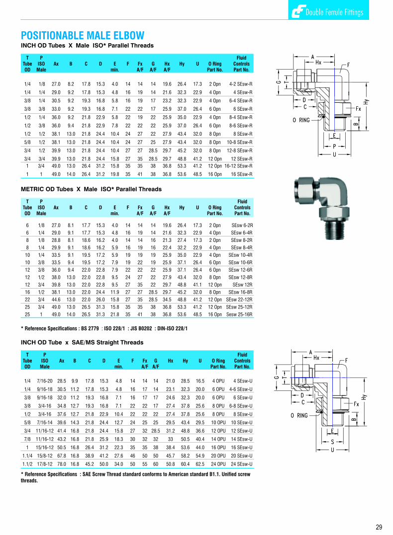
Double Ferrule Fittings Double Ferrule Fittings Double Ferrule Fittings Double Ferrule Fittings
O SEAL MALE CONNECTOR INCH OD Tubes x Male ISO* Parallel Threads
T P Fluid Tube ISO A B C D E F Fd G H O Ring ControlsOD Male min. A/F A/F Part No. Part No.
1/8 1/8 32.8 7.1 15.3 12.7 2.4 19 18.8 11 26.2 2 OPN 2 SCO-R
1/4 1/8 35.0 7.1 17.8 15.3 4.8 19 18.8 14 27.7 2 OPN 4-2 SCO-R
1/4 1/4 40.0 11.2 17.8 15.3 7.1 24 23.6 14 32.6 4OPN 4 SCO-R
3/8 1/4 41.5 11.2 19.3 16.8 7.1 24 23.6 17 34.1 4 OPN 6-4 SCO-R
3/8 3/8 42.2 11.2 19.3 16.8 7.1 30 29.8 17 34.8 6 OPN 6 SCO-R
3/8 1/2 47.7 14.2 19.3 16.8 9.6 32 31.8 17 40.3 8 OPN 6-8 SCO-R
1/2 3/8 44.5 10.4 21.8 22.9 10.4 30 29.8 22 34.4 6 OPN 8-6 SCO-R
1/2 1/2 50.4 14.2 21.8 22.9 11.9 32 31.8 22 40.3 8 OPN 8 SCO-R
5/8 1/2 50.4 14.2 21.8 24.4 11.9 32 31.8 22 40.3 8 OPN 10-8 SCO-R
3/4 1/2 50.4 14.2 21.8 24.4 15.8 32 31.8 28.5 40.3 8 OPN 12-8 SCO-R
3/4 3/4 53.5 15.7 21.8 24.4 15.8 38 37.8 28.5 43.4 12 OPN 12 SCO-R
1 3/4 58.2 15.7 26.4 31.2 22.3 38 37.8 38 46.0 12OPN 16-12 SCO-R
1 1 62.2 18.3 26.4 31.2 27.6 45 44.0 38 50.0 16 OPN 16 SCO-R
1.1/4 1.1/4 77.6 12.0 38.9 41.4 27.6 55 54.0 50 55.6 20 OPN 20 SCO-R
1.1/2 1.1/2 88.9 12.0 45.2 50.0 34.0 60 58.0 57 61.7 24 OPN 24 SCO-R
METRIC OD Tubes x Male ISO* Parallel Threads
T P Fluid Tube ISO A B C D E F Fd G H O Ring ControlsOD Male min. A/F A/F Part No. Part No.
3 1/8 32.8 7.1 15.3 12.9 2.4 19 18.8 11 26.2 2 OPN SCO 3-2 R
3 1/4 37.6 11.2 15.3 12.9 2.4 24 23.8 11 31.0 4 OPN SCO 3-4 R
6 1/4 40.1 11.2 17.7 15.3 4.8 24 23.8 14 32.7 4 OPN SCO 6-4 R
6 3/8 40.8 11.2 17.7 15.3 4.8 30 29.8 14 33.4 6 OPN SCO 6 R
8 1/4 40.9 11.2 18.6 16.2 6.3 24 23.8 16 33.4 4 OPN SCO 8-4 R
10 1/4 41.0 11.2 19.5 17.2 7.1 24 23.8 17 33.4 4 OPN SCO 10-4 R
10 3/8 42.6 11.2 19.5 17.2 7.1 30 29.8 17 35.0 6 OPN SCO 10-6 R
10 1/2 48.0 14.2 19.5 17.2 7.9 32 31.8 17 40.4 8 OPN SCO 10-8 R
12 1/4 44.3 11.2 22.0 22.8 7.1 24 21.8 22 34.2 4 OPN SCO 12-4 R
12 3/8 45.1 11.2 22.0 22.8 7.9 30 29.8 22 34.0 6 OPN SCO 12-6 R
12 1/2 50.5 14.3 22.0 22.8 9.5 32 31.8 22 40.4 8 OPN SCO 12-8 R
16 1/2 50.5 14.3 22.0 24.4 11.9 32 31.8 25 40.4 8 OPN SCO 16-8 R
20 3/4 55.1 15.7 22.0 26.0 15.8 38 37.0 32 45.0 12 OPN SCO 20-2 R
25 3/4 58.1 15.7 26.5 31.3 15.8 38 37.0 38 45.8 12 OPN SCO 25-2 R
25 1 62.3 18.3 26.5 31.3 19.8 45 44.0 38 50.0 16 OPN SCO 25-16 R
* Reference Specifications : BS 2779 : ISO 228/1 : JIS B0202 : DIN-ISO 228/1
INCH OD Tube x Male Straight Threads - UNF
T S Fluid Tube Thread A B C D E F Fd G H O Ring ControlsOD Male min. A/F A/F Part No. Part No.
1/8 5/16 -24 32.8 8.6 15.3 12.7 2.4 14 13.8 11 26.2 1 OPU 2 SCO-U
1/4 7/16 -20 38.4 10.4 17.8 15.3 4.8 19 18.8 14 31.0 2 OPU 4 SCO-U
5/16 1/2 -20 40.6 11.2 18.5 16.3 6.3 22 21.8 16 33.3 3 OPU 5 SCO-U
3/8 9/16 -18 42.4 12.0 19.3 16.8 7.1 24 23.6 17 35.0 4 OPU 6 SCO-U
1/2 3/4 -16 46.0 12.0 21.8 22.9 10.4 28.5 28.0 22 35.8 6 OPU 8 SCO-U
3/4 11/16 -12 52.4 14.3 21.8 24.4 15.8 38 37.8 28.5 42.2 12 OPU 12 SCO-U
1 15/16-12 58.2 14.3 26.4 31.2 22.3 45 44.0 38 46.0 16 OPU 16 SCO-U
1.1/4 15/8-12 76.2 18.3 38.9 41.4 27.6 55 54.0 50 54.1 20 OPU 20 SCO-U
1.1/2 17/8 -12 86.6 19.8 45.2 50.0 34.0 60 58.0 57 59.4 24 OPU 24 SCO-U
POSITIONABLE MALE ELBOWINCH OD Tubes X Male ISO* Parallel Threads
T P FluidTube ISO Ax B C D E F Fx G Hx Hy U O Ring ControlsOD Male min. A/F A/F A/F Part No. Part No.
1/4 1/8 27.0 8.2 17.8 15.3 4.0 14 14 14 19.6 26.4 17.3 2 Opn 4-2 SEsw-R
1/4 1/4 29.0 9.2 17.8 15.3 4.8 16 19 14 21.6 32.3 22.9 4 Opn 4 SEsw-R
3/8 1/4 30.5 9.2 19.3 16.8 5.8 16 19 17 23.2 32.3 22.9 4 Opn 6-4 SEsw-R
3/8 3/8 33.0 9.2 19.3 16.8 7.1 22 22 17 25.9 37.0 26.4 6 Opn 6 SEsw-R
1/2 1/4 36.0 9.2 21.8 22.9 5.8 22 19 22 25.9 35.0 22.9 4 Opn 8-4 SEsw-R
1/2 3/8 36.0 9.4 21.8 22.9 7.8 22 22 22 25.9 37.0 26.4 6 Opn 8-6 SEsw-R
1/2 1/2 38.1 13.0 21.8 24.4 10.4 24 27 22 27.9 43.4 32.0 8 Opn 8 SEsw-R
5/8 1/2 38.1 13.0 21.8 24.4 10.4 24 27 25 27.9 43.4 32.0 8 Opn 10-8 SEsw-R
3/4 1/2 39.9 13.0 21.8 24.4 10.4 27 27 28.5 29.7 45.2 32.0 8 Opn 12-8 SEsw-R
3/4 3/4 39.9 13.0 21.8 24.4 15.8 27 35 28.5 29.7 48.8 41.2 12 Opn 12 SEsw-R
1 3/4 49.0 13.0 26.4 31.2 15.8 35 35 38 36.8 53.3 41.2 12 Opn 16-12 SEsw-R
1 1 49.0 14.0 26.4 31.2 19.8 35 41 38 36.8 53.6 48.5 16 Opn 16 SEsw-R
METRIC OD Tubes X Male ISO* Parallel Threads
T P FluidTube ISO Ax B C D E F Fx G Hx Hy U O Ring ControlsOD Male min. A/F A/F A/F Part No. Part No.
6 1/8 27.0 8.1 17.7 15.3 4.0 14 14 14 19.6 26.4 17.3 2 Opn SEsw 6-2R
6 1/4 29.0 9.1 17.7 15.3 4.8 16 19 14 21.6 32.3 22.9 4 Opn SEsw 6-4R
8 1/8 28.8 8.1 18.6 16.2 4.0 14 14 16 21.3 27.4 17.3 2 Opn SEsw 8-2R
8 1/4 29.9 9.1 18.6 16.2 5.9 16 19 16 22.4 32.2 22.9 4 Opn SEsw 8-4R
10 1/4 33.5 9.1 19.5 17.2 5.9 19 19 19 25.9 35.0 22.9 4 Opn SEsw 10-4R
10 3/8 33.5 9.4 19.5 17.2 7.9 19 22 19 25.9 37.1 26.4 6 Opn SEsw 10-6R
12 3/8 36.0 9.4 22.0 22.8 7.9 22 22 22 25.9 37.1 26.4 6 Opn SEsw 12-6R
12 1/2 38.0 13.0 22.0 22.8 9.5 24 27 22 27.9 43.4 32.0 8 Opn SEsw 12-8R
12 3/4 39.8 13.0 22.0 22.8 9.5 27 35 22 29.7 48.8 41.1 12 Opn SEsw 12R
16 1/2 38.1 13.0 22.0 24.4 11.9 27 27 28.5 29.7 45.2 32.0 8 Opn SEsw 16-8R
22 3/4 44.6 13.0 22.0 26.0 15.8 27 35 28.5 34.5 48.8 41.2 12 Opn SEsw 22-12R
25 3/4 49.0 13.0 26.5 31.3 15.8 35 35 38 36.8 53.3 41.2 12 Opn SEsw 25-12R
25 1 49.0 14.0 26.5 31.3 21.8 35 41 38 36.8 53.6 48.5 16 Opn Sesw 25-16R
* Reference Specifications : BS 2779 : ISO 228/1 : JIS B0202 : DIN-ISO 228/1
INCH OD Tube x SAE/MS Straight Threads
T P FluidTube ISO Ax B C D E F Fx G Hx Hy U O Ring ControlsOD Male min. A/F A/F Part No. Part No.
1/4 7/16-20 28.5 9.9 17.8 15.3 4.8 14 14 14 21.0 28.5 16.5 4 OPU 4 SEsw-U
1/4 9/16-18 30.5 11.2 17.8 15.3 4.8 16 17 14 23.1 32.3 20.0 6 OPU 4-6 SEsw-U
3/8 9/16-18 32.0 11.2 19.3 16.8 7.1 16 17 17 24.6 32.3 20.0 6 OPU 6 SEsw-U
3/8 3/4-16 34.8 12.7 19.3 16.8 7.1 22 22 17 27.4 37.8 25.6 8 OPU 6-8 SEsw-U
1/2 3/4-16 37.6 12.7 21.8 22.9 10.4 22 22 22 27.4 37.8 25.6 8 OPU 8 SEsw-U
5/8 7/16-14 39.6 14.3 21.8 24.4 12.7 24 25 25 29.5 43.4 29.5 10 OPU 10 SEsw-U
3/4 11/16-12 41.4 16.8 21.8 24.4 15.8 27 32 28.5 31.2 48.8 36.6 12 OPU 12 SEsw-U
7/8 11/16-12 43.2 16.8 21.8 25.9 18.3 30 32 32 33 50.5 40.4 14 OPU 14 SEsw-U
1 15/16-12 50.5 16.8 26.4 31.2 22.3 35 35 38 38.4 53.6 44.0 16 OPU 16 SEsw-U
1.1/4 15/8-12 67.8 16.8 38.9 41.2 27.6 46 50 50 45.7 58.2 54.9 20 OPU 20 SEsw-U
1.1/2 17/8-12 78.0 16.8 45.2 50.0 34.0 50 55 60 50.8 60.4 62.5 24 OPU 24 SEsw-U
2924
* Reference Specifications : SAE Screw Thread standard conforms to American standard B1.1. Unified screw threads.
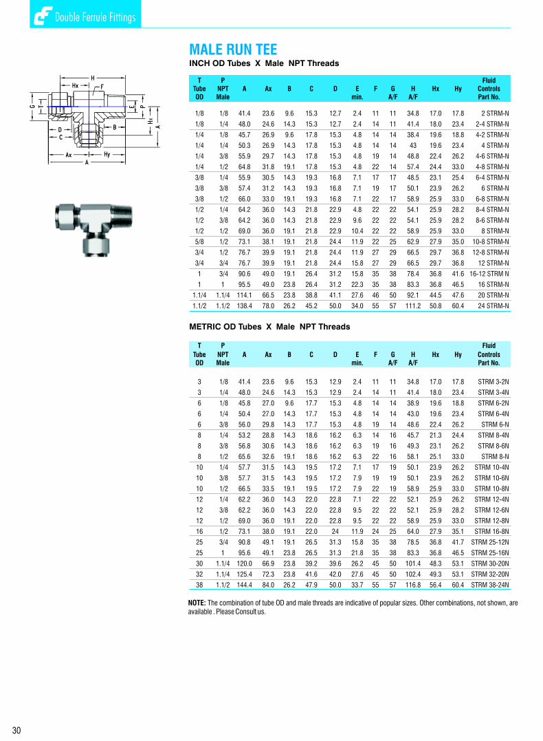
Double Ferrule Fittings Double Ferrule Fittings
30
MALE CONNECTORINCH OD Tubes x Male ISO* Parallel Threads - RS
T P FluidTube ISO A B C D E F Fd G H ControlsOD Male min. A/F A/F Part No..
1/8 1/8 30.0 7.1 15.3 12.7 2.4 14 13.7 11 23.4 2 SCM-Rs
1/8 1/4 35.3 11.2 15.3 12.7 2.4 19 18.0 11 28.7 2-4 SCMN-Rs
1/4 1/8 32.3 7.1 17.8 15.3 4.8 14 13.7 14 24.9 4-2 SCM-Rs
1/4 1/4 37.6 11.2 17.8 15.3 4.8 19 18.0 14 30.2 4 SCM-Rs
1/4 3/8 38.9 11.2 17.8 15.3 4.8 22 21.8 14 31.5 4-6 SCM-Rs
1/4 1/2 44.7 14.2 17.8 15.3 4.8 27 26.0 14 37.4 4-8 SCM-Rs
3/8 1/4 39.2 11.2 19.3 16.8 5.8 19 18.0 17 31.8 6-4 SCM-Rs
3/8 3/8 40.4 11.2 19.3 16.8 7.1 22 21.8 17 33.0 6 SCM-Rs
3/8 1/2 46.3 14.2 19.3 16.8 7.1 27 26.0 17 38.9 6-8 SCM-Rs
1/2 1/4 42.7 11.2 21.8 22.9 5.8 22 18.0 22 32.5 8-4 SCM-Rs
1/2 3/8 43.2 11.2 21.8 22.9 7.9 22 21.8 22 33.0 8-6 SCM-Rs
1/2 1/2 49.0 14.2 21.8 22.9 10.4 27 26.0 22 38.9 8 SCM-Rs
1/2 3/4 52.8 15.7 21.8 22.9 10.4 35 32.0 22 42.7 8-12 SCM-Rs
3/4 1/2 49.0 14.2 21.8 24.4 11.9 27 26.0 28.5 38.9 12-8 SCM-Rs
3/4 3/4 52.8 15.7 21.8 24.4 15.8 35 32.0 28.5 42.7 12 SCM-Rs
3/4 1 55.4 18.3 21.8 24.4 15.8 41 39.0 28.5 45.6 12-16 SCM-Rs
1 1/2 55.9 14.2 26.4 31.2 11.9 35 26.0 38 43.7 16-8 SCM-Rs
1 3/4 57.5 15.7 26.4 31.2 15.8 35 32.0 38 45.2 16-12 SCM-Rs
1 1 60.0 18.3 26.4 31.2 19.8 41 39.0 38 47.8 16 SCM-Rs
1.1/4 1.1/4 78.9 19.8 38.9 41.2 25.0 50 49.0 50 55.9 20 SCM-Rs
1.1/2 1.1/2 90.8 22.1 45.2 50.0 31.8 60 54.7 57 63.2 24 SCM-Rs
METRIC OD Tube x Male ISO* Parallel Threads - RS
T P FluidTube ISO A B C D E F Fd G H ControlsOD Male min. A/F A/F Part No.
3 1/8 30.0 7.1 15.3 12.9 2.4 14 13.8 11 23.4 SCM 3-2 Rs
3 1/4 35.3 11.2 15.3 12.9 2.4 19 18.0 11 28.7 SCM 3-4 Rs
6 1/8 32.3 7.1 17.7 15.3 4.8 14 13.8 14 24.9 SCM 6-2 Rs
6 1/4 37.6 11.2 17.7 15.3 4.8 19 18.0 14 30.2 SCM 6-4 Rs
6 3/8 38.9 11.2 17.7 15.3 4.8 22 21.8 14 31.5 SCM 6- Rs
6 1/2 44.7 14.2 17.7 15.3 4.8 27 26.0 14 37.3 SCM 6-8 Rs
8 1/8 33.2 7.1 18.6 16.2 4.0 14 13.8 16 25.7 SCM 8-2 Rs
8 1/4 38.5 11.2 18.6 16.2 6.4 19 18.0 16 31.0 SCM 8-4 Rs
8 3/8 39.8 11.2 18.6 16.2 6.4 22 21.8 16 32.3 SCM 8-6 Rs
8 1/2 45.6 14.2 18.6 16.2 6.4 27 26.0 16 38.1 SCM 8 Rs
10 1/4 39.4 11.2 19.5 17.2 5.9 19 18.0 19 31.8 SCM 10-4 Rs
10 3/8 40.6 11.2 19.5 17.2 7.6 22 21.8 19 33.0 SCM 10-6 Rs
10 1/2 46.5 14.2 19.5 17.2 7.9 27 26.0 19 38.9 SCM 10-8 Rs
12 1/4 42.6 11.2 22.0 22.8 5.9 22 18.0 22 32.5 SCM 12-4 Rs
12 3/8 43.1 11.2 22.0 22.8 7.9 22 21.8 22 33.0 SCM 12-6 Rs
12 1/2 49.0 14.2 22.0 22.8 9.5 27 26.0 22 38.9 SCM 12-8 Rs
12 3/4 52.8 15.7 22.0 22.8 9.5 35 32.0 22 42.7 SCM 12 Rs
16 3/8 43.9 11.2 22.0 24.4 7.9 24 21.8 25 33.8 SCM 16-6 Rs
16 1/2 49.0 14.2 22.0 24.4 11.9 27 26.0 25 38.9 SCM 16-8 Rs
20 1/2 50.5 14.2 22.0 26.0 11.9 30 26.0 28.5 40.4 SCM 20-8 Rs
20 3/4 52.3 15.7 22.0 26.0 15.9 35 32.0 28.5 42.7 SCM 22-12 Rs
22 3/4 52.3 15.7 22.0 26.0 15.9 35 32.0 32 42.7 SCM 20-16 Rs
22 1 55.3 18.3 22.0 26.0 18.3 41 39.0 32 45.2 SCM 25-12 Rs
25 3/4 57.5 15.7 26.5 31.3 15.9 35 32.0 38 45.2 SCM 20-16 Rs
25 1 60.1 18.3 26.5 31.3 19.8 41 39.0 38 47.8 SCM 20-12 Rs
28 1 70.1 18.3 36.6 36.6 19.8 41 39.0 46 49.3 SCM 28-16 Rs
30 1.1/4 76.5 19.8 39.2 39.6 25.0 50 49.0 50 54.9 SCM 30-20 Rs
32 1.1/4 78.9 19.8 41.6 42.0 25.0 50 49.0 50 55.9 SCM 32-20 Rs
38 1.1/2 90.8 22.1 47.9 49.4 31.8 55 54.7 57 63.2 SCM 38-24 Rs
* Reference Specifications : BS 2779 : ISO 228/1 : JIS B0202 : DIN-ISO 228/1
INCH OD Tubes X Male NPT Threads
T P FluidTube NPT A Ax B C D E F G H Hx Hy ControlsOD Male min. A/F A/F Part No.
1/8 1/8 41.4 23.6 9.6 15.3 12.7 2.4 11 11 34.8 17.0 17.8 2 STRM-N
1/8 1/4 48.0 24.6 14.3 15.3 12.7 2.4 14 11 41.4 18.0 23.4 2-4 STRM-N
1/4 1/8 45.7 26.9 9.6 17.8 15.3 4.8 14 14 38.4 19.6 18.8 4-2 STRM-N
1/4 1/4 50.3 26.9 14.3 17.8 15.3 4.8 14 14 43 19.6 23.4 4 STRM-N
1/4 3/8 55.9 29.7 14.3 17.8 15.3 4.8 19 14 48.8 22.4 26.2 4-6 STRM-N
1/4 1/2 64.8 31.8 19.1 17.8 15.3 4.8 22 14 57.4 24.4 33.0 4-8 STRM-N
3/8 1/4 55.9 30.5 14.3 19.3 16.8 7.1 17 17 48.5 23.1 25.4 6-4 STRM-N
3/8 3/8 57.4 31.2 14.3 19.3 16.8 7.1 19 17 50.1 23.9 26.2 6 STRM-N
3/8 1/2 66.0 33.0 19.1 19.3 16.8 7.1 22 17 58.9 25.9 33.0 6-8 STRM-N
1/2 1/4 64.2 36.0 14.3 21.8 22.9 4.8 22 22 54.1 25.9 28.2 8-4 STRM-N
1/2 3/8 64.2 36.0 14.3 21.8 22.9 9.6 22 22 54.1 25.9 28.2 8-6 STRM-N
1/2 1/2 69.0 36.0 19.1 21.8 22.9 10.4 22 22 58.9 25.9 33.0 8 STRM-N
5/8 1/2 73.1 38.1 19.1 21.8 24.4 11.9 22 25 62.9 27.9 35.0 10-8 STRM-N
3/4 1/2 76.7 39.9 19.1 21.8 24.4 11.9 27 29 66.5 29.7 36.8 12-8 STRM-N
3/4 3/4 76.7 39.9 19.1 21.8 24.4 15.8 27 29 66.5 29.7 36.8 12 STRM-N
1 3/4 90.6 49.0 19.1 26.4 31.2 15.8 35 38 78.4 36.8 41.6 16-12 STRM N
1 1 95.5 49.0 23.8 26.4 31.2 22.3 35 38 83.3 36.8 46.5 16 STRM-N
1.1/4 1.1/4 114.1 66.5 23.8 38.8 41.1 27.6 46 50 92.1 44.5 47.6 20 STRM-N
1.1/2 1.1/2 138.4 78.0 26.2 45.2 50.0 34.0 55 57 111.2 50.8 60.4 24 STRM-N
METRIC OD Tubes X Male NPT Threads
T P Fluid
Tube NPT A Ax B C D E F G H Hx Hy ControlsOD Male min. A/F A/F Part No.
3 1/8 41.4 23.6 9.6 15.3 12.9 2.4 11 11 34.8 17.0 17.8 STRM 3-2N
3 1/4 48.0 24.6 14.3 15.3 12.9 2.4 14 11 41.4 18.0 23.4 STRM 3-4N
6 1/8 45.8 27.0 9.6 17.7 15.3 4.8 14 14 38.9 19.6 18.8 STRM 6-2N
6 1/4 50.4 27.0 14.3 17.7 15.3 4.8 14 14 43.0 19.6 23.4 STRM 6-4N
6 3/8 56.0 29.8 14.3 17.7 15.3 4.8 19 14 48.6 22.4 26.2 STRM 6-N
8 1/4 53.2 28.8 14.3 18.6 16.2 6.3 14 16 45.7 21.3 24.4 STRM 8-4N
8 3/8 56.8 30.6 14.3 18.6 16.2 6.3 19 16 49.3 23.1 26.2 STRM 8-6N
8 1/2 65.6 32.6 19.1 18.6 16.2 6.3 22 16 58.1 25.1 33.0 STRM 8-N
10 1/4 57.7 31.5 14.3 19.5 17.2 7.1 17 19 50.1 23.9 26.2 STRM 10-4N
10 3/8 57.7 31.5 14.3 19.5 17.2 7.9 19 19 50.1 23.9 26.2 STRM 10-6N
10 1/2 66.5 33.5 19.1 19.5 17.2 7.9 22 19 58.9 25.9 33.0 STRM 10-8N
12 1/4 62.2 36.0 14.3 22.0 22.8 7.1 22 22 52.1 25.9 26.2 STRM 12-4N
12 3/8 62.2 36.0 14.3 22.0 22.8 9.5 22 22 52.1 25.9 28.2 STRM 12-6N
12 1/2 69.0 36.0 19.1 22.0 22.8 9.5 22 22 58.9 25.9 33.0 STRM 12-8N
16 1/2 73.1 38.0 19.1 22.0 24 11.9 24 25 64.0 27.9 35.1 STRM 16-8N
25 3/4 90.8 49.1 19.1 26.5 31.3 15.8 35 38 78.5 36.8 41.7 STRM 25-12N
25 1 95.6 49.1 23.8 26.5 31.3 21.8 35 38 83.3 36.8 46.5 STRM 25-16N
30 1.1/4 120.0 66.9 23.8 39.2 39.6 26.2 45 50 101.4 48.3 53.1 STRM 30-20N
32 1.1/4 125.4 72.3 23.8 41.6 42.0 27.6 45 50 102.4 49.3 53.1 STRM 32-20N
38 1.1/2 144.4 84.0 26.2 47.9 50.0 33.7 55 57 116.8 56.4 60.4 STRM 38-24N
MALE RUN TEE
NOTE: The ISO Parallel Thread system shown on this page does not create pressure tight seal against the threads. The seal is made by a bounded washer seal between the fitting and female part face. A soft metal (Copper) Gasket way also be used.
NOTE: The combination of tube OD and male threads are indicative of popular sizes. Other combinations, not shown, are available . Please Consult us.
23
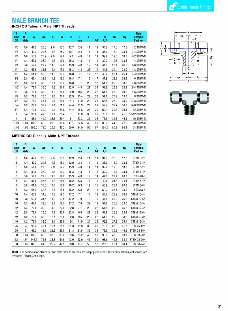
Double Ferrule Fittings Double Ferrule Fittings
INCH OD Tubes x Male NPT Threads
T P FluidTube NPT A Ax B C D E F G H Hx Hy ControlsOD Male min. A/F A/F Part No.
1/8 1/8 47.2 23.6 9.6 15.3 12.7 2.4 11 11 34.0 17.0 17.8 2 STBM-N
1/8 1/4 49.2 24.6 14.3 15.3 12.7 2.4 14 11 36.0 18.0 23.4 2-4 STBM-N
1/4 1/8 53.8 26.9 9.6 17.8 5.3 4.8 14 14 39.2 19.6 18.8 4-2 STBM-N
1/4 1/4 53.8 26.9 14.3 17.8 15.3 4.8 14 14 39.2 19.6 23.4 4 STBM-N
1/4 3/8 59.4 29.7 14.3 17.8 15.3 4.8 19 14 44.8 22.4 26.2 4-6 STBM-N
1/4 1/2 63.6 31.8 19.1 17.8 15.3 4.8 22 14 44.8 24.4 33.0 4-8 STBM-N
3/8 1/4 61.0 30.5 14.3 19.3 16.8 7.1 17 17 46.2 23.1 25.4 6-4 STBM-N
3/8 3/8 62.4 31.2 14.3 19.3 16.8 7.1 19 17 47.8 23.9 26.2 6 STBM-N
3/8 1/2 66.0 33.0 19.1 19.3 16.8 7.1 22 17 51.8 25.9 33.0 6-8 STBM-N
1/2 1/4 72.0 36.0 14.3 21.8 22.9 4.8 22 22 51.8 25.9 28.2 8-4 STBM-N
1/2 3/8 72.0 36.0 14.3 21.8 22.9 9.6 22 22 51.8 25.9 28.2 8-6 STBM-N
1/2 1/2 72.0 36.0 19.1 21.8 22.9 10.4 22 22 51.8 25.9 33.0 8 STBM-N
5/8 1/2 76.2 38.1 19.1 21.8 24.4 11.9 22 25 55.8 27.9 35.0 10-8 STBM-N
3/4 1/2 79.8 39.9 19.1 21.8 24.4 11.9 27 29 59.4 29.7 36.8 12-8 STBM-N
3/4 3/4 79.8 39.9 19.1 21.8 24.4 15.8 27 29 59.4 29.7 36.8 12 STBM-N
1 3/4 98.0 49.0 19.1 26.4 31 15.8 35 38 73.6 36.8 41.6 16-12 STBM-N
1 1 98.0 49.0 23.8 26.4 31 22.3 35 38 73.6 36.8 46.5 16 STBM-N
1.1/4 1.1/4 133.0 66.5 23.8 38.8 41.1 27.6 46 50 89.0 44.5 47.6 20 STBM-N
1.1/2 1.1/2 156.0 78.0 26.2 45.2 50.0 34.0 55 57 101.6 50.8 60.4 24 STBM-N
METRIC OD Tubes x Male NPT Threads
T P FluidTube NPT A Ax B C D E F G H Hx Hy ControlsOD Male min. A/F A/F Part No.
3 1/8 47.2 23.6 9.6 15.3 12.9 2.4 11 11 34.0 17.0 17.8 STBM 3-2N
3 1/4 49.2 24.6 14.3 15.3 12.9 2.4 14 11 36.0 18.0 23.4 STBM 3-4N
6 1/8 54.0 27.0 9.6 17.7 15.3 4.8 14 14 39.2 19.6 18.8 STBM 6-2N
6 1/4 54.0 27.0 14.3 17.7 15.3 4.8 14 14 39.2 19.6 23.4 STBM 6-4N
6 3/8 59.6 29.8 14.3 17.7 15.3 4.8 19 14 44.8 22.4 26.2 STBM 6-N
8 1/4 57.6 28.8 14.3 18.6 16.2 6.3 14 16 42.6 21.3 24.4 STBM 8-4N
8 3/8 61.2 30.6 14.3 18.6 16.2 6.3 19 16 46.2 23.1 26.2 STBM 8-6N
8 1/2 65.2 32.6 19.1 18.6 16.2 6.3 22 16 50.2 25.1 33.0 STBM 8-N
10 1/4 63.0 31.5 14.3 19.5 17.2 7.1 17 19 47.8 23.9 26.2 STBM 10-4N
10 3/8 63.0 31.5 14.3 19.5 17.2 7.9 19 19 47.8 23.9 26.2 STBM 10-6N
10 1/2 67.0 33.5 19.1 19.5 17.2 7.9 22 19 51.8 25.9 33.0 STBM 10-8N
12 1/4 72.0 36.0 14.3 22.0 22.8 7.1 22 22 51.8 25.9 26.2 STBM 12-4N
12 3/8 72.0 36.0 14.3 22.0 22.8 9.5 22 22 51.8 25.9 28.2 STBM 12-6N
12 1/2 72.0 36.0 19.1 22.0 22.8 9.5 22 22 51.8 25.9 33.0 STBM 12-8N
16 1/2 76.0 38.0 19.1 22.0 24 11.9 24 25 55.8 27.9 35.1 STBM 16-8N
25 3/4 98.2 49.1 19.1 26.5 31.3 15.8 35 38 73.6 36.8 41.7 STBM 25-12N
25 1 98.2 49.1 23.8 26.5 31.3 21.8 35 38 73.6 36.8 46.5 STBM 25-16N
30 1.1/4 139.8 66.9 23.8 39.2 39.6 26.2 45 50 96.6 48.3 53.1 STBM 30-20N
32 1.1/4 144.6 72.3 23.8 41.6 42.0 27.6 45 50 98.6 49.3 53.1 STBM 32-20N
38 1.1/2 168.0 84.0 26.2 47.9 50.0 33.7 55 57 112.8 56.4 60.4 STBM 38-24N
MALE BRANCH TEE
NOTE: The combination of tube OD and male threads are indicative of popular sizes. Other combinations, not shown, are available . Please Consult us.
MALE CONNECTORINCH OD Tubes x Male ISO* Parallel Threads - RP
T P FluidTube ISO A B C D E F Fd G H ControlsOD Male min. A/F A/F Part No.
1/8 1/8 30.0 7.1 15.3 12.7 2.4 14 13.7 11 23.4 2 SCM-Rp
1/8 1/4 35.3 11.2 15.3 12.7 2.4 19 18.0 11 28.7 2-4 SCMN-Rp
1/4 1/8 32.3 7.1 17.8 15.3 4.8 14 13.7 14 24.9 4-2 SCM-Rp
1/4 1/4 37.6 11.2 17.8 15.3 4.8 19 18.0 14 30.2 4 SCM-Rp
1/4 3/8 38.9 11.2 17.8 15.3 4.8 22 21.8 14 31.5 4-6 SCM-Rp
1/4 1/2 44.7 14.2 17.8 15.3 4.8 27 26.0 14 37.4 4-8 SCM-Rp
3/8 1/4 39.2 11.2 19.3 16.8 5.8 19 18.0 17 31.8 6-4 SCM-Rp
3/8 3/8 40.4 11.2 19.3 16.8 7.1 22 21.8 17 33.0 6 SCM-Rp
3/8 1/2 46.3 14.2 19.3 16.8 7.1 27 26.0 17 38.9 6-8 SCM-Rp
1/2 1/4 42.7 11.2 21.8 22.9 5.8 22 18.0 22 32.5 8-4 SCM-Rp
1/2 3/8 43.2 11.2 21.8 22.9 7.9 22 21.8 22 33.0 8-6 SCM-Rp
1/2 1/2 49.0 14.2 21.8 22.9 10.4 27 26.0 22 38.9 8 SCM-Rp
1/2 3/4 52.8 15.7 21.8 22.9 10.4 35 32.0 22 42.7 8-12 SCM-Rp
3/4 1/2 49.0 14.2 21.8 24.4 11.9 27 26.0 28.5 38.9 12-8 SCM-Rp
3/4 3/4 52.8 15.7 21.8 24.4 15.8 35 32.0 28.5 42.7 12 SCM-Rp
3/4 1 55.4 18.3 21.8 24.4 15.8 41 39.0 28.5 45.6 12-16 SCM-Rp
1 1/2 55.9 14.2 26.4 31.2 11.9 35 26.0 38 43.7 16-8 SCM-Rp
1 3/4 57.5 15.7 26.4 31.2 15.8 35 32.0 38 45.2 16-12 SCM-Rp
1 1 60.0 18.3 26.4 31.2 19.8 41 39.0 38 47.8 16 SCM-Rp
1.1/4 1.1/4 78.9 19.8 38.9 41.2 25.0 50 49.0 50 55.9 20 SCM-Rp
1.1/2 1.1/2 90.8 22.1 45.2 50.0 31.8 60 54.7 57 63.2 24 SCM-Rp
METRIC OD Tubes x Male ISO* Parallel Threads - RP
T P Fluid
Tube ISO A B C D E F Fd G H ControlsOD Male min. A/F A/F Part No.
3 1/8 30.0 7.1 15.3 12.9 2.4 14 13.8 11 23.4 SCM 3-2Rp
3 1/4 35.3 11.2 15.3 12.9 2.4 19 18.0 11 28.7 SCM 3-4Rp
6 1/8 32.3 7.1 17.7 15.3 4.8 14 13.8 14 24.9 SCM 6-2Rp
6 1/4 37.6 11.2 17.7 15.3 4.8 19 18.0 14 30.2 SCM 6-4Rp
6 3/8 38.9 11.2 17.7 15.3 4.8 22 21.8 14 31.5 SCM 6-Rp
6 1/2 44.7 14.2 17.7 15.3 4.8 27 26.0 14 37.3 SCM 6-8Rp
8 1/8 33.2 7.1 18.6 16.2 4.0 14 13.8 16 25.7 SCM 8-2Rp
8 1/4 38.5 11.2 18.6 16.2 6.4 19 18.0 16 31.0 SCM 8-4Rp
8 3/8 39.8 11.2 18.6 16.2 6.4 22 21.8 16 32.3 SCM 8-6Rp
8 1/2 45.6 14.2 18.6 16.2 6.4 27 26.0 16 38.1 SCM 8-Rp
10 1/4 39.4 11.2 19.5 17.2 5.9 19 18.0 19 31.8 SCM 10-4Rp
10 3/8 40.6 11.2 19.5 17.2 7.6 22 21.8 19 33.0 SCM 10-6Rp
10 1/2 46.5 14.2 19.5 17.2 7.9 27 26.0 19 38.9 SCM 10-8Rp
12 1/4 42.6 11.2 22.0 22.8 5.9 22 18.0 22 32.5 SCM 12-4Rp
12 3/8 43.1 11.2 22.0 22.8 7.9 22 21.8 22 33.0 SCM 12-6Rp
12 1/2 49.0 14.2 22.0 22.8 9.5 27 26.0 22 38.9 SCM 12-8Rp
12 3/4 52.8 15.7 22.0 22.8 9.5 35 32.0 22 42.7 SCM 12Rp
16 3/8 43.9 11.2 22.0 24.4 7.9 24 21.8 25 33.8 SCM 16-6Rp
16 1/2 49.0 14.2 22.0 24.4 11.9 27 26.0 25 38.9 SCM 16-8Rp
20 1/2 50.5 14.2 22.0 26.0 11.9 30 26.0 28.5 40.4 SCM 20-8Rp
20 3/4 52.3 15.7 22.0 26.0 15.9 35 32.0 28.5 42.7 SCM 22-12Rp
22 3/4 52.3 15.7 22.0 26.0 15.9 35 32.0 32 42.7 SCM 20-16Rp
22 1 55.3 18.3 22.0 26.0 18.3 41 39.0 32 45.2 SCM 25-12Rp
25 3/4 57.5 15.7 26.5 31.3 15.9 35 32.0 38 45.2 SCM 20-16Rp
25 1 60.1 18.3 26.5 31.3 19.8 41 39.0 38 47.8 SCM 20-12Rp
28 1 70.1 18.3 36.6 36.6 19.8 41 39.0 46 49.3 SCM 28-16Rp
30 1.1/4 76.5 19.8 39.2 39.6 25.0 50 49.0 50 54.9 SCM 30-20Rp
32 1.1/4 78.9 19.8 41.6 42.0 25.0 50 49.0 50 55.9 SCM 32-20Rp
38 1.1/2 90.8 22.1 47.9 49.4 31.8 55 54.7 57 63.2 SCM 38-24Rp
* Reference Specifications : BS 2779 : ISO 228/1 : JIS B 0202 : DIN-ISO 228/1
22 31
NOTE: The ISO parallel Thread System RP shown on this page does not create pressure tight seal against the threads. The seal is made by metal to metal contact against the female part. A sof t metal (usually annealed copper) gasket between the fitting and the part face.
BORED - THROUGH FITTINGS FOR THERMOCOUPLE ARE AVAILABLE WITH ISO P ARALLEL MALE THREADS. Add suffix “BT” to the above part numbers above.
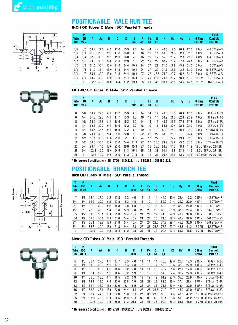
Double Ferrule Fittings Double Ferrule Fittings
MALE CONNECTORMETRIC OD Tubes x Male ISO* Tapered Pipe Thread
T P Fluid Tube ISO A B C D E F G H ControlsOD Male min. A/F A/F Part No.
3 1/8 30.5 9.6 15.3 12.9 2.4 11 11 23.9 SCM 3-2 Rx
3 1/4 35.6 14.3 15.3 12.9 2.4 14 11 29.0 SCM 3-4 Rx
6 1/8 32.8 9.6 17.7 15.3 4.8 14 14 25.4 SCM 6-2 Rx
6 1/4 37.9 14.3 17.7 15.3 4.8 14 14 30.5 SCM 6-4 Rx
6 3/8 38.4 14.3 17.7 15.3 4.8 19 14 31.0 SCM 6 Rx
6 1/2 44.7 19.1 17.7 15.3 4.8 22 14 37.3 SCM 6-8 Rx
8 1/8 34.2 9.6 18.6 16.2 4.8 14 16 26.7 SCM 8-2 Rx
8 1/4 38.7 14.3 18.6 16.2 6.3 14 16 31.2 SCM 8-4 Rx
8 3/8 39.3 14.3 18.6 16.2 6.3 19 16 31.8 SCM 8-6 Rx
8 1/2 45.6 19.1 18.6 16.2 6.3 22 16 38.1 SCM 8 Rx
10 1/8 36.3 9.6 19.5 17.2 4.8 17 19 28.7 SCM 10-2 Rx
10 1/4 40.9 14.3 19.5 17.2 7.9 19 19 33.3 SCM 10-4 Rx
10 3/8 40.9 14.3 19.5 17.2 7.9 19 19 33.3 SCM 10-6 Rx
10 1/2 46.5 19.1 19.5 17.2 7.9 22 19 38.9 SCM 10-8 Rx
12 1/4 43.4 14.3 22.0 22.8 7.1 22 22 33.3 SCM 12-4 Rx
12 3/8 43.4 14.3 22.0 22.8 9.5 22 22 33.3 SCM 12-6 Rx
12 1/2 49.0 19.1 22.0 22.8 9.5 22 22 38.9 SCM 12-8 Rx
12 3/4 50.5 19.1 22.0 22.8 9.5 27 22 40.4 SCM 12 Rx
12 1 57.1 23.8 22.0 22.8 9.5 35 22 47.0 SCM 12-16 Rx
14 3/8 44.1 14.3 22.0 24.4 9.5 24 25 34.0 SCM 14-6 Rx
14 1/2 49.0 19.1 22.0 24.4 11.1 24 25 38.9 SCM 14-8 Rx
15 1/2 49.0 19.1 22.0 24.4 11.9 24 25 38.9 SCM 15 8 Rx
16 3/8 44.1 14.3 22.0 24.4 9.5 24 25 34.0 SCM 16-6 Rx
16 1/2 49.0 19.1 22.0 24.4 11.9 24 25 38.9 SCM 16-8 Rx
16 3/4 50.5 19.1 22.0 24.4 12.7 27 25 40.4 SCM 16-12 Rx
18 1/2 50.5 19.1 22.0 24.4 11.9 27 30 40.4 SCM 18-8 Rx
18 3/4 50.5 19.1 22.0 24.4 15.1 27 30 40.4 SCM 18-12 Rx
20 1/2 52.3 19.1 22.0 26.0 11.9 30 32 42.2 SCM 20-8 Rx
20 3/4 52.3 19.1 22.0 26.0 15.9 30 32 42.2 SCM 20-12 Rx
22 3/4 52.3 19.1 22.0 26.0 15.9 30 32 42.2 SCM 22-12 Rx
22 1 57.1 23.8 22.0 26.0 18.3 35 32 47.0 SCM 22 16 Rx
25 1/2 57.5 19.1 26.5 31.3 11.9 35 38 45.2 SCM 25- 8 Rx
25 3/4 57.5 19.1 26.5 31.3 15.8 35 38 45.2 SCM 25-12 Rx
25 1 62.3 23.8 26.5 31.3 21.8 35 38 50.0 SCM 25-16 Rx
28 1 72.4 23.8 36.6 36.6 21.8 41 46 51.6 SCM 28-16 Rx
28 1.1/4 73.1 23.8 36.6 36.6 21.8 46 46 52.3 SCM 28-20 Rx
30 1.1/4 77.2 23.8 39.2 39.6 26.2 46 50 55.6 SCM30-20 RX
32 1.1/4 79.6 23.8 41.6 42.0 28.6 46 50 56.6 SCM32-20 Rx
38 1.1/2 96.6 26.2 47.9 49.4 33.7 55 57 64.0 SCM 38-24 Rx
* Reference Specifications : BS 21: ISO 7/1 : JIS B 0203 : DIN 2999 : IS 554
32
POSITIONABLE MALE RUN TEE INCH OD Tubes X Male ISO* Parallel Threads
T P FluidTube ISO A Ax B C D E F Fx G H Hx Hy U O Ring ControlsOD Male min. A/F A/F A/F Part No. Part No.
1/4 1/8 53.4 27.0 8.2 17.8 15.3 4.0 14 14 14 46.0 19.6 26.4 17.3 2 Opn 4-2 STRsw-R 1/4 1/4 61.3 29.0 9.2 17.8 15.3 4.8 16 19 14 53.9 21.6 32.3 22.9 4 Opn 4 STRsw-R
3/8 1/4 62.8 30.5 9.2 19.3 16.8 5.8 16 19 17 55.5 23.2 32.3 22.9 4 Opn 6-4 STRsw-R
1/2 3/8 73.0 36.0 9.4 21.8 22.9 7.8 22 22 22 62.9 25.9 37.0 26.4 6 Opn 8-6 STRsw-R
1/2 1/2 81.5 38.1 13.0 21.8 24.4 10.4 24 27 22 71.3 27.9 43.4 32.0 8 Opn 8 STRsw-R
5/8 1/2 81.5 38.1 13.0 21.8 24.4 10.4 24 27 25 71.3 27.9 43.4 32.0 8 Opn 10-8 STRsw-R
3/4 1/2 85.1 39.9 13.0 21.8 24.4 10.4 27 27 28.5 74.9 29.7 45.2 32.0 8 Opn 12-8 STRsw-R
3/4 3/4 88.7 39.9 13.0 21.8 24.4 15.8 27 35 28.5 78.5 29.7 48.8 41.2 12 Opn 12 STRsw-R
1 1 102.6 49.0 14.0 26.4 31.2 19.8 35 41 38 90.4 36.8 53.6 48.5 16 Opn 16 STRSw-R
METRIC OD Tubes X Male ISO* Parallel Threads
T P FluidTube ISO A Ax B C D E F Fx G H Hx Hy U O Ring ControlsOD Male min. A/F A/F A/F Part No. Part No.
6 1/8 53.4 27.0 8.1 17.7 15.3 4.0 14 14 14 46.0 19.6 26.4 17.3 2 Opn STR sw 6-2R
6 1/4 61.3 29.0 9.1 17.7 15.3 4.8 16 19 14 53.9 21.6 32.3 22.9 4 Opn STR sw 6-4R
8 1/8 56.2 28.8 8.1 18.6 16.2 4.0 14 14 16 48.7 21.3 27.4 17.3 2 Opn STR sw 8-2R
8 1/4 62.1 29.9 9.1 18.6 16.2 5.9 16 19 16 54.6 22.4 32.2 22.9 4 Opn STR sw 8-4R
10 1/4 68.5 33.5 9.1 19.5 17.2 5.9 19 19 19 61.9 25.9 35.0 22.9 4 Opn STR sw 10-4R
12 3/8 73.1 36.0 9.4 22.0 22.8 7.9 22 22 22 63.0 25.9 37.1 26.4 6 Opn STR sw 12-6R
12 1/2 81.4 38.0 13.0 22.0 23 9.5 24 27 22 71.3 27.9 43.4 32.0 8 Opn STR sw 12-8R
16 1/2 83.3 38.1 13.0 22.0 24.4 11.9 27 27 28.5 74.9 29.7 45.2 32.0 8 Opn STR sw 16-8R
22 3/4 93.4 44.6 13.0 22.0 26.0 15.8 27 35 28.5 83.3 34.5 48.8 41.2 12 OpnSTR sw 22-12R
25 3/4 102.3 49.0 13.0 26.5 31.3 15.8 35 35 38 90.1 36.8 53.3 41.2 12 OpnSTR sw 25-12R
25 1 102.6 49.0 14.0 26.5 31.3 21.8 35 41 38 90.4 36.8 53.6 48.5 16 OpnSTR sw 25-16R
Inch OD Tubes X Male ISO* Parallel Thread
T P FluidTube ISO A Ax B C D E F Fx G H Hx Hy U O Ring ControlsOD Male min. A/F A/F A/F Part No. Part No.
1/4 1/8 53.4 27.0 8.2 17.8 15.3 4.0 14 14 14 46.0 19.6 26.4 17.3 2 OPN 4-2 STBsw-R
1/4 1/4 61.3 29.0 9.2 17.8 15.3 4.8 16 19 14 53.9 21.6 32.3 22.9 4 OPN 4 STBsw-R
3/8 1/4 62.8 30.5 9.2 19.3 16.8 5.8 16 19 17 55.5 23.2 32.3 22.9 4 OPN 6-4 STBsw-R
1/2 3/8 73.0 36.0 9.4 21.8 22.9 7.8 22 22 22 62.9 25.9 37.0 26.4 6 OPN 8-6 STBsw-R
1/2 1/2 81.5 38.1 13.0 21.8 24.4 10.4 24 27 22 71.3 27.9 43.4 32.0 8 OPN 8 STBsw-R
5/8 1/2 81.5 38.1 13.0 21.8 24.4 10.4 24 27 25 71.3 27.9 43.4 32.0 8 OPN 10-8 STBsw-R
3/4 1/2 85.1 39.9 13.0 21.8 24.4 10.4 27 27 28.5 74.9 29.7 45.2 32.0 8 OPN 12-8 STBsw-R
3/4 3/4 88.7 39.9 13.0 21.8 24.4 15.8 27 35 28.5 78.5 29.7 48.8 41.2 12 OPN 12 STBsw-R
1 1 102.6 49.0 14.0 26.4 31.2 19.8 35 41 38 90.4 36.8 53.6 48.5 16 OPN 16 STBsw-R
Metric OD Tubes X Male ISO* Parallel Threads
T P FluidTube ISO A AX B C D E F FX G H HX HY U O Ring ControlsOD MALE min. A/F A/F A/F Part No. Part No.
6 1/8 53.4 27.0 8.1 17.7 15.3 4.0 14 14 14 46.0 19.6 26.4 17.3 2 OPN STBsw 6-2R6 1/4 61.3 29.0 9.1 17.7 15.3 4.8 16 19 14 53.9 21.6 32.3 22.9 4 OPN STBsw 6-4R
8 1/8 56.2 28.8 8.1 18.6 16.2 4.0 14 14 16 48.7 21.3 27.4 17.3 2 OPN STBsw 8-2R
8 1/4 62.1 29.9 9.1 18.6 16.2 5.9 16 19 16 54.6 22.4 32.2 22.9 4 OPN STBsw 8-4R
10 1/4 68.5 33.5 9.1 19.5 17.2 5.9 19 19 19 61.9 25.9 35.0 22.9 4 OPN STBsw 10-4R
12 3/8 73.1 36.0 9.4 22.0 22.8 7.9 22 22 22 63.0 25.9 37.1 26.4 6 OPN STBsw 12-6R
12 1/2 81.4 38.0 13.0 22.0 23 9.5 24 27 22 71.3 27.9 43.4 32.0 8 OPN STBsw 12-8R
16 1/2 83.3 38.1 13.0 22.0 24.4 11.9 27 27 28.5 74.9 29.7 45.2 32.0 8 OPN STBsw 16-8R
22 3/4 93.4 44.6 13.0 22.0 26.0 15.8 27 35 28.5 83.3 34.5 48.8 41.2 12 OPN STBsw 22-12R
25 3/4 102.3 49.0 13.0 26.5 31.3 15.8 35 35 38 90.1 36.8 53.3 41.2 12 OPN STBsw 25-12R25 1 102.6 49.0 14.0 26.5 31.3 21.8 35 41 38 90.4 36.8 53.6 48.5 16 OPN STBsw 25-16R
* Reference Specifications : BS 2779 : ISO 228/1 : JIS B0202 : DIN-ISO 228/1
POSITIONABLE BRANCH TEE
* Reference Specifications : BS 2779 : ISO 228/1 : JIS B0202 : DIN-ISO 228/1
21
Bored-Through Fittings for Thermocouples
To order, add BT to the desired Fluid Controls Male Connector Part Number : 8 SCM - Rx. BTExample : Bored Through Connection 1/2” OD x 1/2” ISO Tapered Male Pipe Thread 1/2” OD through bore has part number.

Double Ferrule Fittings Double Ferrule Fittings
POSITIONABLE MALE RUN TEE INCH OD Tubes x SAE/MS *Straight threads
T S Fluid Tube SAE/MS A Ax B C D E F Fx G H Hx Hy U O Ring ControlsOD Male min. A/F A/F A/F Part No. Part No.
1/4 7/16-20 57.0 28.5 9.9 17.8 15.3 4.8 14 14 14 49.5 21.0 28.5 16.5 4 OPU 4 STRsw-U
3/8 9/16-18 64.3 32.0 11.2 19.3 16.8 7.1 16 17 17 56.9 24.6 32.3 20.0 6 OPU 6 STRsw-U
1/2 3/4-16 75.4 37.6 12.7 21.8 22.9 10.4 22 22 22 65.2 27.4 37.8 25.6 8 OPU 8 STRsw-U
3/4 11/16-12 90.2 41.4 16.8 21.8 24.4 15.8 27 32 28.5 80.0 31.2 48.8 36.6 12 OPU 12 STRsw-U
1 15/16-12 104.1 50.5 16.8 26.4 31.2 22.3 35 35 38 92.0 38.4 53.6 44.0 16 OPU 16 STRsw-U
1.1/4 15/8-12 126.0 67.8 16.8 38.9 41.2 27.6 46 50 50 103.9 45.7 58.2 54.9 20 OPU 20 STRsw-U
1.1/2 17/8-12 138.4 78.0 16.8 45.2 50.0 34.0 50 55 60 111.2 50.8 60.4 62.5 24 OPU 24 STRsw-U
METRIC OD Tubes x SAE/MS *Straight threads
T S Fluid Tube SAE/MS A Ax B C D E F Fx G H Hx Hy U O Ring ControlsOD Male min. A/F A/F A/F Part No. Part No.
6 7/16-20 57.0 28.5 9.9 17.7 15.3 4.8 14 14 14 49.5 21.0 28.5 16.5 4 OPU STRsw-6-U
10 9/16-18 64.3 32.0 11.2 19.5 17.2 7.1 16 17 17 56.9 24.6 32.3 20.0 6 OPU STRsw-10-U
12 3/4-16 75.4 37.6 12.7 22.0 22.8 10.4 22 22 22 65.2 27.4 37.8 25.6 8 OPU STRsw-12-U
20 11/16-12 90.2 41.4 16.8 22.0 26.0 15.8 27 32 28.5 80.0 31.2 48.8 36.6 12 OPU STRsw-20-U
25 15/16-12 104.1 50.5 16.8 26.5 31.3 22.3 35 35 38 92.0 38.4 53.6 44.0 16 OPU STRsw-25-U
2 15/8-12 126.0 67.8 16.8 41.6 42.0 27.6 46 50 50 103.9 45.7 58.2 54.9 20 OPU STRsw-32-U
38 17/8-12 138.4 78.0 16.8 47.6 49.4 34.0 50 55 60 111.2 50.8 60.4 62.5 24 OPU STRsw-38-U
INCH OD Tubes x SAE/MS *Straight threads
T S Fluid Tube SAE/MS A Ax B C D E F Fx G H Hx Hy U O Ring ControlsOD Male min. A/F A/F A/F Part No. Part No.
1/4 7/16-20 57.0 28.5 9.9 17.8 15.3 4.8 14 14 14 42.0 21.0 28.5 16.5 4 OPU 4 STBsw-U
3/8 9/16-18 64.0 32.0 11.2 19.3 16.8 7.1 16 17 17 49.2 24.6 32.3 20.0 6 OPU 6 STBsw-U
1/2 3/4-16 75.2 37.6 12.7 21.8 22.9 10.4 22 22 22 54.8 27.4 37.8 25.6 8 OPU 8 STBsw-U
3/4 11/16-12 82.8 41.4 16.8 21.8 24 15.8 27 32 28.5 62.4 31.2 48.8 36.6 12 OPU12 STBsw-U
1 15/16-12 101.0 50.5 16.8 26.4 31.2 22.3 35 35 38 76.8 38.4 53.6 44.0 16 OPU16 STBsw-U
1.1/4 15/8-12 135.6 68 16.8 38.9 41.2 27.6 46 50 50 91.4 46 58 55 20 OPU20 STBsw-U
1.1/2 17/8-12 156.0 78.0 16.8 45.2 50.0 34.0 50 55 60 101.6 51 60 63 24 OPU24 STBsw-U
METRIC OD Tubes x SAE/MS *Straight threads T S Fluid Tube SAE/MS A Ax B C D E F Fx G H Hx Hy U O Ring ControlsOD Male min. A/F A/F A/F Part No. Part No.
6 7/16-20 57.0 28.5 9.9 17.7 15.3 4.8 14 14 14 42.0 21.0 28.5 16.5 4 OPU STBsw-6-U
10 9/16-18 64.0 32.0 11.2 19.5 17.2 7.1 16 17 17 49.2 24.6 32.3 20.0 6 OPU STBsw-10-U
12 3/ -16 75.2 37.6 12.7 22.0 22.8 10.4 22 22 22 54.8 27.4 37.8 25.6 8 OPU STBsw-12-U
20 11/16-12 82.8 41.4 16.8 22.0 26.0 15.8 27 32 28.5 62.4 31.2 48.8 36.6 12 OPUSTBsw-20-U
25 15/16-12 101.0 50.5 16.8 26.5 31.3 22.3 35 35 38 76.8 38.4 53.6 44.0 16 OPUSTBsw-25-U
32 15/8-12 135.6 68 16.8 41.6 42.0 27.6 46 50 50 91.4 46 58 55 20 OPUSTBsw-32-U
38 17/8-12 156.0 78.0 16.8 47.6 49.4 34.0 50 55 60 101.6 51 60 63 24 OPUSTBsw-38-U
POSITIONABLE MALE BRANCH TEE
METRIC OD Tubes x Male NPT Threads
T P Fluid Tube NPT A B C D E F G H ControlsOD Male min. A/F A/F Part No.
3 1/8 30.5 9.6 15.3 12.9 2.4 11 11 23.9 SCM 3-2N
3 1/4 35.6 14.3 15.3 12.9 2.4 14 11 29.0 SCM 3-4N
6 1/8 32.8 9.6 17.7 15.3 4.8 14 14 25.4 SCM 6-2N
6 1/4 37.9 14.3 17.7 15.3 4.8 14 14 30.5 SCM 6-4N
6 3/8 38.4 14.3 17.7 15.3 4.8 19 14 31.0 SCM 6-N
6 1/2 44.7 19.1 17.7 15.3 4.8 22 14 37.3 SCM 6-8N
8 1/8 34.2 9.6 18.6 16.2 4.8 14 16 26.7 SCM 8-2N
8 1/4 38.7 14.3 18.6 16.2 6.3 14 16 31.2 SCM 8-4N
8 3/8 39.3 14.3 18.6 16.2 6.3 19 16 31.8 SCM 8-6N
8 1/2 45.6 19.1 18.6 16.2 6.3 22 16 38.1 SCM 8-N
10 1/8 36.3 9.6 19.5 17.2 4.8 17 19 28.7 SCM 10-2N
10 1/4 40.9 14.3 19.5 17.2 7.9 19 19 33.3 SCM 10-4N
10 3/8 40.9 14.3 19.5 17.2 7.9 19 19 33.3 SCM 10-6N
10 1/2 46.5 19.1 19.5 17.2 7.9 22 19 38.9 SCM 10-8N
12 1/4 43.4 14.3 22.0 22.8 7.1 22 22 33.3 SCM 12-4N
12 3/8 43.4 14.3 22.0 22.8 9.5 22 22 33.3 SCM 12-6N
12 1/2 49.0 19.1 22.0 22.8 9.5 22 22 38.9 SCM 12-8N
12 3/4 50.5 19.1 22.0 22.8 9.5 27 22 40.4 SCM 12-N
12 1 57.1 23.8 22.0 22.8 9.5 35 22 47.0 SCM 12-16N
14 1/4 44.1 14.3 22.0 24.4 7.1 24 25 34.0 SCM 14-4N
14 3/8 44.1 14.3 22.0 24.4 9.5 24 25 34.0 SCM 14-6N
14 1/2 49.0 19.1 22.0 24.4 11.1 24 25 38.9 SCM 14-8N
15 1/2 49.0 19.1 22.0 24.4 11.9 24 25 38.9 SCM 15 8N
16 3/8 44.1 14.3 22.0 24.4 9.5 24 25 34.0 SCM 16-6N
16 1/2 49.0 19.1 22.0 24.4 11.9 24 25 38.9 SCM 16-8N
16 3/4 50.5 19.1 22.0 24.4 12.7 27 25 40.4 SCM 16-12N
18 1/2 50.5 19.1 22.0 24.4 11.9 27 30 40.4 SCM 18-8N
18 3/4 50.5 19.1 22.0 24.4 15.1 27 30 40.4 SCM 18-12N
20 1/2 52.3 19.1 22.0 26.0 11.9 30 32 42.2 SCM 20-8N
20 3/4 52.3 19.1 22.0 26.0 15.9 30 32 42.2 SCM 20-12N
22 3/4 52.3 19.1 22.0 26.0 15.9 30 32 42.2 SCM 22-12N
22 1 57.1 23.8 22.0 26.0 18.3 35 32 47.0 SCM 22 16N
25 1/2 57.5 19.1 26.5 31.3 11.9 35 38 45.2 SCM 25- 8N
25 3/4 57.5 19.1 26.5 31.3 15.8 35 38 45.2 SCM 25-12N
25 1 62.3 23.8 26.5 31.3 21.8 35 38 50.0 SCM 25-16N
28 1 72.4 23.8 36.6 36.6 21.8 41 46 51.6 SCM 28-16N
28 1.1/4 73.1 23.8 36.6 36.6 21.8 46 46 52.3 SCM 28-20N
30 1.1/4 77.2 23.8 39.2 39.6 26.2 46 50 55.6 SCM 30-20N
32 1.1/4 79.6 23.8 41.6 42.0 28.6 46 50 56.6 SCM 32-20N
38 1.1/2 96.6 26.2 47.9 49.4 33.7 55 57 64.0 SCM 38-24N
MALE CONNECTOR
20 33
* Reference Specifications : SAE Screw Thread standard conforms to American standard B1.1. Unified screw threads.
Bored-Through Fittings for Thermocouples
To order, add BT to the desired Fluid Controls Male Connector Part Number : 8 SCM - N. BTExample : Bored Through Connection 1/2” OD x 1/2” NPT (M) with 1/2” OD through bore has part number.

Double Ferrule Fittings Double Ferrule Fittings
MALE CONNECTORINCH OD Tubes X Male NPT Threads
T P FluidTube NPT A B C D E F G H ControlsOD Male min. A/F A/F Part No.
1/16 1/16 23.9 9.6 11.0 8.6 1.3 8 8 20.0 1 SCM-N
1/16 1/8 26.2 9.6 11.0 8.6 1.3 14 8 22.4 1-2 SCMN-N
1/8 1/8 30.5 9.6 15.3 12.7 2.4 11 11 23.9 2 SCM-N
1/8 1/4 35.6 14.3 15.3 12.7 2.4 14 11 29.0 2-4 SCMN-N
1/4 1/8 32.8 9.6 17.8 15.3 4.8 14 14 25.4 4-2 SCM-N
1/4 1/4 37.8 14.3 17.8 15.3 4.8 14 14 30.5 4 SCM-N
1/4 3/8 38.4 14.3 17.8 15.3 4.8 19 14 31.0 4-6 SCM-N
1/4 1/2 44.7 19.1 17.8 15.3 4.8 22 14 37.4 4-8 SCM-N
5/16 1/4 38.6 14.3 18.5 16.3 6.3 14 16 31.2 5-4 SCM-N
3/8 1/8 35.3 9.6 19.3 16.8 4.8 16 17 27.9 6-2 SCM-N
3/8 1/4 39.8 14.3 19.3 16.8 7.1 16 17 32.5 6-4 SCM-N
3/8 3/8 39.8 14.3 19.3 16.8 7.1 19 17 32.5 6 SCM-N
3/8 1/2 41.2 19.1 19.3 16.8 7.1 22 17 38.9 6-8 SCM-N
1/2 1/4 43.4 14.3 21.8 22.9 7.1 22 22 33.3 8-4 SCM-N
1/2 3/8 43.4 14.3 21.8 22.9 9.6 22 22 33.3 8-6 SCM-N
1/2 1/2 49.0 19.1 21.8 22.9 10.4 22 22 38.9 8 SCM-N
1/2 3/4 50.5 19.1 21.8 22.9 10.4 27 22 40.4 8-12 SCM-N
1/2 1 57.1 23.8 21.8 22.9 10.4 35 22 47.0 8-16 SCM-N
5/8 3/8 44.2 14.3 21.8 24.4 9.6 24 25 34.0 10-6 SCM-N
5/8 1/2 49.0 19.1 21.8 24.4 10.4 24 25 38.9 10-8 SCM-N
3/4 1/2 50.5 19.1 21.8 24.4 10.4 27 28.5 40.4 12-8 SCM-N
3/4 3/4 50.5 19.1 21.8 24.4 15.8 27 28.5 40.4 12 SCM-N
3/4 1 57.1 23.8 21.8 24.4 15.8 35 28.5 47.0 12-16 SCM-N
7/8 3/4 50.5 19.1 21.8 26.0 15.8 30 32 40.4 14-12 SCM-N
1 1/2 57.4 19.1 26.4 31.2 10.4 35 38 45.2 16-8 SCM-N
1 3/4 57.4 19.1 26.4 31.2 15.8 35 38 45.2 16-12 SCM-N
1 1 62.2 23.8 26.4 31.2 22.3 35 38 50.0 16 SCM-N
1.1/4 1 77.2 23.8 38.9 41.2 22.3 46 50 55.2 20-16 SCM-N
1.1/4 1.1/4 77.2 23.8 38.9 41.2 27.6 46 50 55.2 20 SCM-N
1.1/2 1.1/2 88.9 26.2 45.2 50.0 34.0 55 57 61.7 24 SCM-N
2 2 113.5 26.9 62.7 67.6 46.0 70 76 76.2 32 SCM-N
INCH OD Tubes X Male ISO * Tapered Pipe Threads
T P FluidTube ISO A B C D E F G H ControlsOD Male min. A/F A/F Part No.
1/8 1/8 30.5 9.6 15.3 12.7 2.4 11 11 23.9 2 SCM-Rx
1/8 1/4 35.6 14.3 15.3 12.7 2.4 14 11 29.0 2-4 SCMN-Rx
1/4 1/8 32.8 9.6 17.8 15.3 4.8 14 14 25.4 4-2 SCM-Rx
1/4 1/4 37.8 14.3 17.8 15.3 4.8 14 14 30.1 4 SCM-Rx
1/4 3/8 38.4 14.3 17.8 15.3 4.8 19 14 31.0 4-6 SCM-Rx
1/4 1/2 44.7 19.1 17.8 15.3 4.8 22 14 37.4 4-8 SCM-Rx
3/8 1/8 35.3 9.6 19.3 16.8 4.8 16 17 27.9 6-2 SCM-Rx
3/8 1/4 39.8 14.3 19.3 16.8 7.1 16 17 32.5 6-4 SCM-Rx
3/8 3/8 39.8 14.3 19.3 16.8 7.1 19 17 32.5 6 SCM-Rx
3/8 1/2 41.2 19.1 19.3 16.8 7.1 22 17 38.9 6-8 SCM-Rx
1/2 1/4 43.4 14.3 21.8 22.9 7.1 22 22 33.3 8-4 SCM-Rx
1/2 3/8 43.4 14.3 21.8 22.9 9.6 22 22 33.3 8-6 SCM-Rx
1/2 1/2 49.0 19.1 21.8 22.9 10.4 22 22 38.9 8 SCM-Rx
3/4 3/4 50.5 19.1 21.8 24.4 15.8 27 28.5 40.4 12 SCM-Rx
1 1 62.2 23.8 26.4 31.2 22.3 35 38 50.0 16 SCM-Rx
1.1/4 1 77.2 23.8 38.9 41.2 22.3 46 50 55.2 20-16 SCM-Rx
1.1/4 1.1/4 77.2 23.8 38.9 41.2 27.6 46 50 55.2 20 SCM-Rx
1.1/2 1.1/2 88.9 26.2 45.2 50.0 34.0 55 57 61.7 24 SCM-Rx
* Reference Specifications : BS 21 : ISO 7/1 : JIS B 0203 : DIN 2999 : IS 554
FEMALE CONNECTORINCH OD Tubes x Female NPT Threads
T P FluidTube NPT A B C D E F G H ControlsOD Female min. A/F A/F Part No.
1/16 1/16 23.6 9.9 11.0 8.6 1.3 11 8 19.8 1 SCF-N
1/16 18 24.4 10.4 11.0 8.6 1.3 14 8 20.6 1-2 SCF-N
1/8 1/8 28.7 10.4 15.3 12.7 2.4 14 11 22.1 2 SCF-N
1/8 1/4 33.6 15.0 15.3 12.7 2.4 19 11 26.9 2-4 SCF-N
1/4 1/8 31.2 9.9 17.8 15.3 4.8 14 14 23.9 4-2 SCF-N
1/4 1/4 35.8 15.0 17.8 15.3 4.8 19 14 28.5 4 SCF-N
1/4 3/8 37.6 15.0 17.8 15.3 4.8 22 14 30.2 4-6 SCF-N
1/4 1/2 42.4 19.8 17.8 15.3 4.8 27 14 35.0 4-8 SCF-N
5/16 1/8 32.0 10.4 18.5 16.3 6.3 14 16 24.6 5-2 SCF-N
5/16 1/4 36.8 15.0 18.5 16.3 6.3 19 16 29.5 5-4 SCF-N
3/8 1/8 32.8 10.4 19.3 16.8 7.1 16 17 25.4 6-2 SCF-N
3/8 1/4 37.6 15.0 19.3 16.8 7.1 19 17 30.2 6-4 SCF-N
3/8 3/8 39.1 15.0 19.3 16.8 7.1 22 17 31.8 6 SCF-N
3/8 1/2 43.9 19.8 19.3 16.8 7.1 27 17 36.6 6-8 SCF-N
1/2 1/4 40.4 15.0 21.8 22.9 10.4 22 22 30.2 8-4 SCF-N
1/2 3/8 41.9 15.0 21.8 22.9 10.4 22 22 30.2 8-6 SCF-N
1/2 1/2 46.7 19.8 21.8 22.9 10.4 27 22 36.6 8 SCF-N
1/2 3/4 48.3 20.6 21.8 22.9 10.4 32 22 38.1 8-12 SCF-N
5/8 3/8 41.9 15.0 21.8 24.4 12.7 24 25 31.8 10-6 SCF-N
5/8 1/2 46.7 19.8 21.8 24.4 12.7 27 25 36.6 10-8 SCF-N
3/4 1/2 46.7 19.8 21.8 24.4 15.8 27 28.5 36.6 12-8 SCF-N
3/4 3/4 48.3 20.6 21.8 24.4 15.8 35 28.5 38.1 12 SCF-N
7/8 3/4 49.8 20.6 21.8 25.9 18.3 35 32 39.6 14-12 SCF-N
1 3/4 53.4 20.6 26.4 31.2 22.3 35 38 41.2 16-12 SCF-N
1 1 62.3 25.4 26.4 31.2 22.3 41 38 50.0 16 SCF-N
1.1/4 1.1/4 74.6 25.4 38.9 41.2 27.6 55 50 52.6 20 SCF-N
1.1/2 1.1/2 83.3 27.6 45.2 50.0 34.0 60 60 56.2 24 SCF-N
INCH OD Tubes x Female ISO* Tapered Pipe Threads
T P Fluid
Tube ISO A B C D E F G H ControlsOD Female min. A/F A/F Part No.
1/16 1/16 23.6 9.9 11.0 8.6 1.3 11 8 19.8 1 SCF-Rx
1/8 1/8 28.7 10.4 15.3 12.7 2.4 14 11 22.1 2 SCF-Rx
1/8 1/4 33.6 15.0 15.3 12.7 2.4 19 11 26.9 2-4 SCF-Rx
1/4 1/8 31.2 9.9 17.8 15.3 4.8 14 14 23.9 4-2 SCF-Rx
1/4 1/4 35.8 15.0 17.8 15.3 4.8 19 14 28.5 4 SCF-Rx
1/4 3/8 37.6 15.0 17.8 15.3 4.8 22 14 30.2 4-6 SCF-Rx
1/4 1/2 42.4 19.8 17.8 15.3 4.8 27 14 35.0 4-8 SCF-Rx
3/8 1/4 37.6 15.0 19.3 16.8 7.1 19 17 30.2 6-4 SCF-Rx
3/8 3/8 39.1 15.0 19.3 16.8 7.1 22 17 31.8 6 SCF-Rx
3/8 1/2 43.9 19.8 19.3 16.8 7.1 27 17 36.6 6-8 SCF-Rx
1/2 1/4 40.4 15.0 21.8 22.9 10.4 22 22 40.4 8-4 SCF-Rx
1/2 3/8 41.9 15.0 21.8 22.9 10.4 22 22 30.2 8-6 SCF-Rx
1/2 1/2 46.7 19.8 21.8 22.9 10.4 27 22 31.8 8 SCF-Rx
3/4 1/2 46.7 19.8 21.8 24.4 15.8 27 28.5 36.6 12-8 SCF-Rx
3/4 3/4 48.3 20.6 21.8 24.4 15.8 35 28.5 38.1 12 SCF-Rx
1 3/4 53.4 20.6 26.4 31.2 22.3 35 38 41.2 16-12 SCF-Rx
1 1 62.3 25.4 26.4 31.2 22.3 41 38 50.0 16 SCF-Rx
1.1/4 1.1/4 74.6 25.4 38.9 41.2 27.6 55 50 52.6 20 SCF-Rx
1.1/2 1.1/2 83.3 27.6 45.2 50.0 34.0 60 60 56.2 24 SCF-Rx
* Reference Specifications : BS 21: ISO 7/1 : JIS B 0203 : DIN 2999 : IS 554
* Female connectors with Parallel ISO Female Threads to BS:2779; ISO 228/1; JIS B6202; DIN 259 are also Available. Their Dimensions are as same as ISO. Tapered Pipe Threads above. Please consult us.
34 19
NOTE: The combination of tube OD and male threads are indicative of popular sizes. Other combinations, not shown, are available . Please Consult us.
BORED - THROUGH CONNECTORS available in all these sizes. Add suffix “BT” to the above part numbers to designate bored - trough male connector.
NOTE: The combinations shown above are representative of various possibilities. Other combinations not shown are also available. Please consult us.
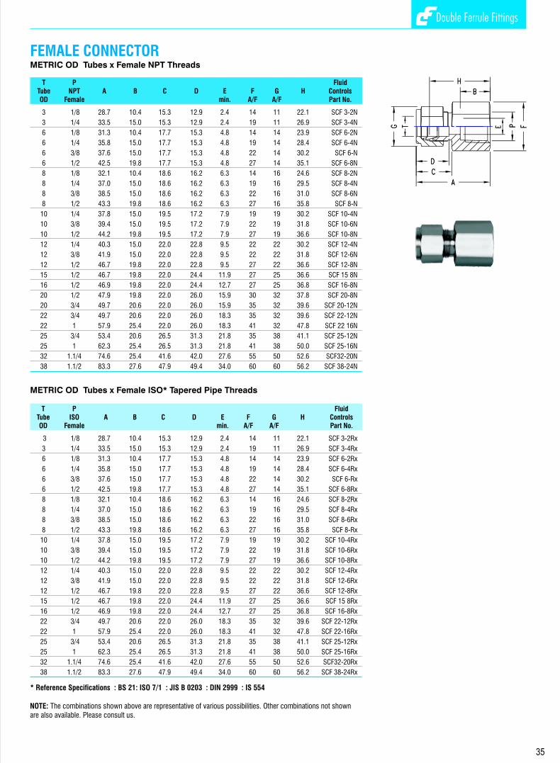
Double Ferrule Fittings Double Ferrule Fittings
UNION CROSSINCH OD Tubes
T FluidTube A Ax C D E F G H Hx ControlsOD min. A/F A/F Part No.
1/8 44.8 22.4 15.3 12.7 2.4 11 11 31.6 15.8 2 SK
1/4 53.8 26.9 17.8 15.3 4.8 14 14 39.2 19.6 4 SK
3/8 61.0 30.5 19.3 16.8 7.1 17 17 46.4 23.2 6 SK
1/2 72.0 36.0 21.8 22.9 10.4 22 22 51.8 25.9 8 SK
3/4 79.8 39.9 21.8 24.4 15.8 27 28.5 59.4 29.7 12 SK
1 98.0 49.0 26.4 31.2 22.3 35 38 73.6 36.8 16 SK
METRIC OD Tubes
T FluidTube A Ax C D E F G H Hx ControlsOD min. A/F A/F Part No.
3 44.6 22.3 15.3 12.9 2.4 11 11 31.4 15.7 SK-3
6 54.0 27.0 17.7 15.3 4.8 14 14 39.2 19.6 SK-6
8 57.6 28.8 18.6 16.2 6.3 16 16 42.6 21.3 SK-8
10 63.0 31.5 19.5 17.2 7.9 17 19 47.8 23.9 SK-10
12 72.0 36.0 22.0 22.8 9.5 22 22 51.8 25.9 SK-12
16 76.0 38.0 22.0 24.4 12.7 24 25 55.8 27.9 SK-16
22 89.2 44.6 22.0 26.0 18.3 32 32 69.0 34.5 SK-22
25 98.2 49.1 26.5 31.3 21.8 35 38 73.6 36.8 SK-25
18
FEMALE CONNECTORMETRIC OD Tubes x Female NPT Threads
T P FluidTube NPT A B C D E F G H ControlsOD Female min. A/F A/F Part No.
METRIC OD Tubes x Female ISO* Tapered Pipe Threads
T P FluidTube ISO A B C D E F G H ControlsOD Female min. A/F A/F Part No.
* Reference Specifications : BS 21: ISO 7/1 : JIS B 0203 : DIN 2999 : IS 554
3 1/8 28.7 10.4 15.3 12.9 2.4 14 11 22.1 SCF 3-2N
3 1/4 33.5 15.0 15.3 12.9 2.4 19 11 26.9 SCF 3-4N
6 1/8 31.3 10.4 17.7 15.3 4.8 14 14 23.9 SCF 6-2N
6 1/4 35.8 15.0 17.7 15.3 4.8 19 14 28.4 SCF 6-4N
6 3/8 37.6 15.0 17.7 15.3 4.8 22 14 30.2 SCF 6-N
6 1/2 42.5 19.8 17.7 15.3 4.8 27 14 35.1 SCF 6-8N
8 1/8 32.1 10.4 18.6 16.2 6.3 14 16 24.6 SCF 8-2N
8 1/4 37.0 15.0 18.6 16.2 6.3 19 16 29.5 SCF 8-4N
8 3/8 38.5 15.0 18.6 16.2 6.3 22 16 31.0 SCF 8-6N
8 1/2 43.3 19.8 18.6 16.2 6.3 27 16 35.8 SCF 8-N
10 1/4 37.8 15.0 19.5 17.2 7.9 19 19 30.2 SCF 10-4N
10 3/8 39.4 15.0 19.5 17.2 7.9 22 19 31.8 SCF 10-6N
10 1/2 44.2 19.8 19.5 17.2 7.9 27 19 36.6 SCF 10-8N
12 1/4 40.3 15.0 22.0 22.8 9.5 22 22 30.2 SCF 12-4N
12 3/8 41.9 15.0 22.0 22.8 9.5 22 22 31.8 SCF 12-6N
12 1/2 46.7 19.8 22.0 22.8 9.5 27 22 36.6 SCF 12-8N
15 1/2 46.7 19.8 22.0 24.4 11.9 27 25 36.6 SCF 15 8N
16 1/2 46.9 19.8 22.0 24.4 12.7 27 25 36.8 SCF 16-8N
20 1/2 47.9 19.8 22.0 26.0 15.9 30 32 37.8 SCF 20-8N
20 3/4 49.7 20.6 22.0 26.0 15.9 35 32 39.6 SCF 20-12N
22 3/4 49.7 20.6 22.0 26.0 18.3 35 32 39.6 SCF 22-12N
22 1 57.9 25.4 22.0 26.0 18.3 41 32 47.8 SCF 22 16N
25 3/4 53.4 20.6 26.5 31.3 21.8 35 38 41.1 SCF 25-12N
25 1 62.3 25.4 26.5 31.3 21.8 41 38 50.0 SCF 25-16N
32 1.1/4 74.6 25.4 41.6 42.0 27.6 55 50 52.6 SCF32-20N
38 1.1/2 83.3 27.6 47.9 49.4 34.0 60 60 56.2 SCF 38-24N
3 1/8 28.7 10.4 15.3 12.9 2.4 14 11 22.1 SCF 3-2Rx
3 1/4 33.5 15.0 15.3 12.9 2.4 19 11 26.9 SCF 3-4Rx
6 1/8 31.3 10.4 17.7 15.3 4.8 14 14 23.9 SCF 6-2Rx
6 1/4 35.8 15.0 17.7 15.3 4.8 19 14 28.4 SCF 6-4Rx
6 3/8 37.6 15.0 17.7 15.3 4.8 22 14 30.2 SCF 6-Rx
6 1/2 42.5 19.8 17.7 15.3 4.8 27 14 35.1 SCF 6-8Rx
8 1/8 32.1 10.4 18.6 16.2 6.3 14 16 24.6 SCF 8-2Rx
8 1/4 37.0 15.0 18.6 16.2 6.3 19 16 29.5 SCF 8-4Rx
8 3/8 38.5 15.0 18.6 16.2 6.3 22 16 31.0 SCF 8-6Rx
8 1/2 43.3 19.8 18.6 16.2 6.3 27 16 35.8 SCF 8-Rx
10 1/4 37.8 15.0 19.5 17.2 7.9 19 19 30.2 SCF 10-4Rx
10 3/8 39.4 15.0 19.5 17.2 7.9 22 19 31.8 SCF 10-6Rx
10 1/2 44.2 19.8 19.5 17.2 7.9 27 19 36.6 SCF 10-8Rx
12 1/4 40.3 15.0 22.0 22.8 9.5 22 22 30.2 SCF 12-4Rx
12 3/8 41.9 15.0 22.0 22.8 9.5 22 22 31.8 SCF 12-6Rx
12 1/2 46.7 19.8 22.0 22.8 9.5 27 22 36.6 SCF 12-8Rx
15 1/2 46.7 19.8 22.0 24.4 11.9 27 25 36.6 SCF 15 8Rx
16 1/2 46.9 19.8 22.0 24.4 12.7 27 25 36.8 SCF 16-8Rx
22 3/4 49.7 20.6 22.0 26.0 18.3 35 32 39.6 SCF 22-12Rx
22 1 57.9 25.4 22.0 26.0 18.3 41 32 47.8 SCF 22-16Rx
25 3/4 53.4 20.6 26.5 31.3 21.8 35 38 41.1 SCF 25-12Rx
25 1 62.3 25.4 26.5 31.3 21.8 41 38 50.0 SCF 25-16Rx
32 1.1/4 74.6 25.4 41.6 42.0 27.6 55 50 52.6 SCF32-20Rx
38 1.1/2 83.3 27.6 47.9 49.4 34.0 60 60 56.2 SCF 38-24Rx
35
NOTE: Reducing Cross with variation in the tube sizes are available. The tube sizes are designated in the order given below.
The tube sizes are indicated in the part number in the same order above.
4
3
1 2
NOTE: The combinations shown above are representative of various possibilities. Other combinations not shown are also available. Please consult us.

Double Ferrule Fittings Double Ferrule Fittings
11 22
33
11 22
33
17
REDUCING UNION TEEINCH OD Tubes
T Tx FluidTubeTube A Ax Ay C Cx D Dx E F G Gx H Hx Hy ControlsOD OD min. A/F A/F A/F Part No.
3/8 1/4 61.0 30.5 29.0 19.3 17.8 16.8 15.3 4.8 16 17 14 46.2 23.1 21.6 6/6/4 STR
1/2 1/4 72.2 36.0 31.8 21.8 17.8 22.9 15.3 4.8 22 22 14 51.8 25.9 24.4 8/8/4 STR
1/2 3/8 72.2 36.0 33.3 21.8 19.3 22.9 16.8 7.1 22 22 17 51.8 25.9 25.9 8/8/6 STR
3/4 3/8 79.8 39.9 37.0 21.8 19.3 24.4 16.8 7.1 27 28.5 17 59.4 29.7 29.7 12/12/6 STR
3/4 1/2 79.8 39.9 39.9 21.8 21.8 24.4 22.9 10.4 27 28.5 22 59.4 29.7 29.7 12/12/ 8STR
1 3/8 98.0 49.0 41.9 26.4 19.3 31.2 16.8 7.1 35 38 17 73.6 36.8 34.5 16/16/A6 STR
1 1/2 98.0 49.0 44.7 26.4 22.9 31.2 21.8 10.4 35 38 22 73.6 36.8 34.5 16/16/8 STR
1 3/4 98.0 49.0 44.7 26.4 24.4 31.2 24.4 15.8 35 38 28.5 73.6 36.8 34.5 16/16/12 STR
1.1/4 1 135.6 67.8 55.1 38.9 26.4 41.2 31.2 22.3 46 50 38 91.4 45.7 42.9 20/20/16 STR
1.1/2 1 157.5 78.7 60.0 44.7 26.4 50.0 31.2 22.3 55 57 38 103.2 51.6 47.8 24/24/16 STR
INCH OD Tubes
T Tx FluidTubeTube A Ax Ay C Cx D Dx E F G Gx H Hx Hy ControlsOD OD min. A/F A/F A/F Part No.
3/8 1/4 59.4 30.5 29.0 19.3 17.8 16.8 15.3 4.8 16 17 14 44.7 23.1 21.6 6/4/6 STR
1/2 1/4 67.7 36.0 31.7 21.8 17.8 22.9 15.3 4.8 22 22 14 50.2 25.9 24.3 8/4/8 STR
1/2 3/8 69.3 36.0 33.3 21.8 19.3 22.9 16.8 7.1 22 22 17 51.8 25.9 25.9 8/6/8 STR
3/4 3/8 77.0 39.9 37.1 21.8 19.3 24.4 16.8 7.1 27 28.5 17 59.4 29.7 29.7 12/6/12 STR
3/4 1/2 79.8 39.9 39.9 21.8 21.8 24.4 22.9 10.4 27 28.5 22 59.4 29.7 29.7 12/8/12STR
1 3/8 98.9 49.0 41.9 26.4 19.3 31.2 16.8 7.1 35 38 17 71.3 36.8 34.5 16/6/16 STR
1 1/2 93.7 49.0 44.7 26.4 21.8 31.2 21.8 10.4 35 38 22 71.3 36.8 34.5 16/8/16 STR
1 3/4 93.7 49.0 44.7 26.4 21.8 31.2 24.4 15.8 35 38 28.5 71.3 36.8 34.5 16/12/16 STR
1.1/4 1 119.6 67.8 53.0 38.9 26.4 41.2 31.2 18.2 46 50 38 85.3 45.7 40.8 20/16/20 STR
1.1/2 1 150.9 78.7 72.9 45.2 38.9 50.0 41.3 27.6 55 57 38 101.6 50.8 50.8 24/20/24 STR
INCH OD Tubes
T Tx FluidTubeTube A Ax Ay C Cx D Dx E F G Gx H Hx Hy ControlsOD OD min. A/F A/F A/F Part No.
3/8 1/4 59.6 30.6 29.0 19.3 17.8 16.8 15.3 4.8 16 17 14 44.8 23.2 21.6 6/4/4 STR
1/2 1/4 67.7 36.0 31.7 21.8 17.8 22.9 15.3 4.8 22 22 14 50.2 25.9 24.3 8/4/4 STR
1/2 3/8 69.3 36.0 33.2 21.8 19.3 22.9 16.8 7.1 22 22 17 51.8 25.9 25.9 8/6/6 STR
3/4 3/8 77.0 38.9 37.0 21.8 19.3 24.4 16.8 7.1 27 28.5 17 59.4 29.7 29.7 12/6/6 STR
3/4 1/2 79.8 39.9 39.9 21.8 21.8 24.4 22.9 10.4 27 28.5 22 59.4 29.7 29.7 12/8/ 8STR
1 3/8 99.9 39.9 41.9 26.4 19.3 31.2 16.8 7.1 35 38 17 71.3 36.8 34.5 16/6/6 STR
1 1/2 93.7 49.0 44.7 26.4 22.9 31.2 21.8 10.4 35 38 22 71.3 36.8 34.5 16/8/8 STR
1 3/4 93.7 49.0 44.7 26.4 24.4 31.2 24.4 15.8 35 38 28.5 71.3 36.8 34.5 16/12/12 STR
1.1/4 1 122.9 67.8 55.1 38.9 26.4 41.2 31.2 22.3 46 50 38 88.6 45.7 42.9 20/16/16 STR
1.1/2 1 138.7 78.7 60.0 44.7 26.4 50.0 31.2 22.3 50 57 38 99.4 51.6 47.8 24/16/16 STR
11 22
33
33
11 22
FEMALE MANOMETER CONNECTOR Inch OD Tubes X Female Iso* Parallel Threads (gage)
T P F G FluidTube ISO A B C D E A/F A/F H a2 d4 b t2 ControlsOD Female min. Minm.Minm. Part No.
1/4 1/4 37.6 13.0 17.8 15.3 4.8 19 14 30.2 1.6 5.6 9.4 17.0 4 SCF-MAN
1/4 3/8 37.6 14.2 17.8 15.3 4.8 24 14 30.2 1.6 6.6 9.9 20.3 4-6 SCF-MAN
1/4 1/2 43.4 18.8 17.8 15.3 4.8 27 14 36.0 1.6 6.6 14.5 24.9 4-8 SCF-MAN
5/16 1/4 38.4 13.0 18.5 16.3 6.0 19 16 31.0 1.6 - 9.4 - 5-4 SCF-MAN
5/16 1/2 40.9 18.8 18.5 16.3 7.1 27 16 33.6 1.6 - 14.5 - 5-8 SCF-MAN
3/8 1/4 39.2 13.0 19.3 16.8 6.0 19 17 31.8 1.6 - 9.4 - 6-4 SCF-MAN
3/8 3/8 38.6 14.2 19.3 16.8 6.6 24 17 31.2 1.6 - 9.9 - 6 SCF-MAN
3/8 1/2 41.9 18.8 19.3 16.8 7.1 27 17 34.5 1.6 - 14.5 - 6-8 SCF-MAN
1/2 3/8 44.5 14.2 21.8 22.9 6.6 24 22 34.3 1.6 - 9.9 - 8-6 SCF-MAN
1/2 1/2 48.3 18.8 21.8 22.9 7.1 27 22 38.1 1.6 - 14.5 - 8 SCF-MAN
Metric OD Tubes X Female ISO* Parallel Thread (gage)
T P F G FluidTube ISO A B C D E A/F A/F H a2 b d4 t2 ControlsOD Female min. min min Part No.
3 1/4 35.3 12.9 15.3 12.9 2.4 19 11 28.7 1.6 9.5 5.5 17.0 SCF 3-4MAN
6 1/4 37.6 12.9 17.7 15.3 4.8 19 14 30.2 1.6 9.5 5.5 17.0 SCF 6-4MAN
6 3/8 37.6 14.1 17.7 15.3 4.8 24 14 30.2 1.6 10.0 6.5 20.3 SCF 6MAN
6 1/2 43.5 18.9 17.7 15.3 4.8 27 14 36.1 1.6 14.5 7.0 24.9 SCF 6-8MAN
8 1/4 38.5 12.9 18.6 16.2 5.5 19 16 31.0 1.6 9.5 5.5 - SCF 8-4MAN
8 3/8 36.2 14.1 18.6 16.2 6.5 24 16 28.7 1.6 10.0 6.5 - SCF 8-6MAN
8 1/2 41.0 18.9 18.6 16.2 7.1 27 16 33.5 1.6 14.5 7.0 - SCF 8MAN
10 1/4 39.4 19.5 19.5 17.2 5.5 19 19 31.8 1.6 9.5 5.5 - SCF 10-4MAN
10 3/8 38.8 19.5 19.5 17.2 6.5 24 19 31.2 1.6 10.0 6.5 - SCF 10-6MAN
10 1/2 42.1 19.5 19.5 17.2 7.1 27 19 34.5 1.6 14.5 7.0 - SCF 10-8MAN
12 1/4 41.9 12.9 22.0 22.8 5.5 22 22 31.8 1.6 9.5 5.5 - SCF 12-4MAN
12 3/8 44.4 14.1 22.0 22.8 6.5 24 22 34.3 1.6 10.0 6.5 - SCF12-6MAN
12 1/2 48.2 18.9 22.0 22.8 7.1 27 22 38.1 1.6 14.5 7.0 - SCF 12-8MAN
No seal is made around the male thread. instead, a gasket is dropped into the flat bottom in the female thread, and the end of the male threaded end exerts a load on the gasket to seal. Details of gasket given below.
* Reference Specifications : BS 2779 : ISO 228/1 : JIS B0202 : DIN-259
36
NOTE: 1. The order of the sizes is as per the designation (1-2-3) in figure shown above.
NOTE: The combinations shown above are representative of various possibilities. Other combinations not shown are also available. Please consult us.
P Part No.
ISO E H Tx
Female Copper PTFE
1/4” 7.6 1.8 10.7 4 MG-Cu 4 MG-PTFE
3/8” 8.6 2.3 14.2 6 MG-Cu 6 MG-PTFE
1/2” 9.1 2.5 17.8 8 MG-Cu 8 MG-PTFE
MANOMETER CONNECTOR GASKET FOR FEMALE ISO PARALLEL THREADS
t2

Double Ferrule Fittings Double Ferrule Fittings Double Ferrule Fittings Double Ferrule Fittings
16
INCH OD Tubes
T Fluid Tube A Ax C D E F G H Hx ControlsOD min. A/F A/F Part No.
1/16 35.6 17.8 11.0 8.6 1.3 11 8 28.0 14.0 1 ST
1/8 44.8 22.4 15.3 12.7 2.4 11 11 31.6 15.8 2 ST
1/4 53.8 26.9 17.8 15.3 4.8 14 14 39.2 19.6 4 ST
5/16 57.4 28.7 18.5 16.3 6.3 16 16 42.6 21.3 5 ST
3/8 61.0 30.5 19.3 16.8 7.1 17 17 46.4 23.2 6 ST
1/2 72.0 36.0 21.8 22.9 10.4 22 22 51.8 25.9 8 ST
5/8 76.2 38.1 21.8 24.4 12.7 24 25 55.8 27.9 10 ST
3/4 79.8 39.9 21.8 24.4 15.8 27 28.5 59.4 29.7 12 ST
7/8 89.4 44.7 21.8 25.9 18.2 35 32 69.2 34.6 14 ST
1 98.0 49.0 26.4 31.2 22.3 35 38 73.6 36.8 16 ST
1.1/4 133.2 66.6 38.9 41.2 27.6 46 50 89.0 44.5 20 ST
1.1/2 156.0 78.0 45.2 50.0 34.0 55 57 101.6 50.8 24 ST
2 214.4 107.4 62.7 67.9 46.0 70 76 139.8 69.9 32 ST
METRIC OD Tubes
T Fluid Tube A Ax C D E F G H Hx ControlsOD min. A/F A/F Part No.
3 44.6 22.3 15.3 12.9 2.4 11 11 31.4 15.7 ST-3
6 54.0 27.0 17.7 15.3 4.8 14 14 39.2 19.6 ST-6
8 57.6 28.8 18.6 16.2 6.3 16 16 42.6 21.3 ST-8
10 63.0 31.5 19.5 17.2 7.9 17 19 47.8 23.9 ST-10
12 72.0 36.0 22.0 22.8 9.5 22 22 51.8 25.9 ST-12
14 76.0 38.0 22.0 24.4 11.1 24 25 55.8 27.9 ST-14
15 76.0 38.0 22.0 24.4 11.9 24 25 55.8 27.9 ST-15
16 76.0 38.0 22.0 24.4 12.7 24 25 55.8 27.9 ST-16
18 79.6 39.8 22.0 24.4 15.1 27 30 59.4 29.7 ST-18
20 89.2 44.6 22.0 26.0 15.9 32 32 69.0 34.5 ST-20
22 89.2 44.6 22.0 26.0 18.3 32 32 69.0 34.5 ST-22
25 98.2 49.1 26.5 31.3 21.8 35 38 73.6 36.8 ST-25
28 128.0 64.0 36.6 36.6 21.8 41 46 87.0 43.5 ST-28
30 139.8 69.9 39.2 39.6 26.2 46 50 96.6 48.3 ST-30
32 144.6 72.3 41.6 42.0 28.6 46 50 98.6 49.3 ST-32
38 168.0 84.0 47.9 49.4 33.7 55 57 112.8 56.4 ST-38
UNION TEE BULKHEAD FEMALE CONNECTOR INCH OD Tubes x Female NPT Threads
T P Panel Max. FluidTube NPT A Ax B D E F G H Hx Hole Panel ControlsOD Male min. A/F A/F Drill Thick- Part No.
Size ness
1/8 1/8 44.7 31.2 10.4 12.7 2.4 14 11 38.1 24.6 8.3 12.7 2 SCFB-N
1/4 1/8 47.0 33.5 10.4 15.3 4.8 16 14 39.7 26.2 11.5 10.2 4-2 SCFB-N
1/4 1/4 51.5 33.5 15.0 15.3 4.8 19 14 44.2 26.2 11.5 10.2 4 SCFB-N
3/8 1/4 54.8 36.8 15.0 16.8 7.1 19 17 47.5 29.5 14.7 11.2 6-4 SCFB-N
1/2 3/8 61.7 41.9 15.0 22.9 10.4 22 22 51.6 31.0 19.5 12.7 8-6 SCFB-N
1/2 1/2 66.7 41.9 19.8 22.9 10.4 27 22 56.6 31.0 19.5 12.7 8 SCFB-N
5/8 1/2 67.6 42.7 19.8 22.9 12.7 27 25 57.4 32.5 22.6 12.7 10-8 SCFB-N
3/4 1/2 72.4 47.5 19.8 24.4 16.0 35 28.5 62.3 37.4 25.8 16.8 12-8 SCFB-N
3/4 3/4 74.7 47.5 20.6 24.4 16.0 35 28.5 64.3 37.4 25.8 16.8 12 SCFB-N
1 3/4 84.3 57.4 20.6 31.2 16.0 35 38 72.1 45.2 33.7 19.0 16-12 SCFB-N
1 1 93.2 57.4 25.4 31.2 22.2 35 38 81.0 45.2 33.7 19.0 16 SCFB-N
1.1/4 1.1/4 105.7 69.9 25.4 41.2 27.6 50 50 83.5 47.7 41.6 19.0 20 SCFB-N
1.1/2 1.1/2 144.5 76.4 27.6 50.0 34.0 60 57 87.4 49.3 49.6 19.0 24 SCFB-N
Metric OD Tubes x Female NPT Threads
T P Panel Max. FluidTube NPT A Ax B D E F G H Hx Hole Panel ControlsOD Male min. A/F A/F Drill Thick- Part No.
Size ness
3 1/8 44.7 31.2 10.4 12.9 2.4 14 11 38.1 24.6 8.3 12.7 SCFB 3-2N
6 1/4 51.6 33.6 15.0 15.3 4.8 19 14 44.2 26.2 11.5 10.2 SCFB 6-4N
10 3/8 56.8 37.0 15.0 17.2 7.9 22 19 49.2 29.4 16.3 11.2 SCFB 10-4N
12 3/8 61.8 41.9 15.0 22.8 9.5 24 22 51.7 31.8 19.5 12.7 SCFB 12-6N
12 1/2 66.7 41.9 19.8 22.8 9.5 27 22 56.6 31.8 19.5 12.7 SCFB 12-8N
16 1/2 67.5 42.6 20.6 24.4 12.7 27 25 57.4 32.5 22.8 12.7 SCFB 16-8N
22 3/4 79.9 53.0 20.6 26.0 15.8 35 35 69.8 42.9 29.0 19.0 SCFB 22-12N
25 3/4 84.3 57.4 20.6 31.2 15.8 35 38 72.1 45.2 33.7 19.0 SCFB 25-12N
25 1 93.2 57.4 25.4 31.2 22.3 35 38 81.0 45.2 33.7 19.0 SCFB 25-16N
32 1.1/4 105.7 69.9 25.4 42.0 27.6 50 50 83.5 44.7 41.6 19.0 SCFB 32-20N
38 1.1/2 114.5 76.4 27.6 49.4 33.7 60 57 87.4 49.3 49.6 19.0 SCFB 38-24N
37
NOTE: Bulkhead Female Connectors are also available with ISO Taper Female Threads, ISO Parallel Female Threads and ISO Female Marcometer connection. Please consult us.

Double Ferrule Fittings Double Ferrule Fittings
15
INCH OD Tubes
T FluidTube A C D E F G Hx ControlsOD min. A/F Part No.
1/16 17.8 11.0 8.6 1.3 11 8 14.0 1 SE
1/8 22.4 15.3 12.7 2.4 11 11 15.8 2 SE
1/4 26.9 17.8 15.3 4.8 14 14 19.6 4 SE
5/16 28.7 18.5 16.3 6.3 16 16 21.3 5 SE
3/8 30.5 19.3 16.8 7.1 17 17 23.2 6 SE
1/2 36.0 21.8 22.9 10.4 22 22 25.9 8 SE
5/8 38.1 21.8 24.4 12.7 24 25 27.9 10 SE
3/4 39.9 21.8 24.4 15.8 27 28.5 29.7 12 SE
7/8 44.7 21.8 25.9 18.2 35 32 34.6 14 SE
1 49.0 26.4 31.2 22.3 35 38 36.8 16 SE
1.1/4 66.6 38.9 41.2 27.6 46 50 44.5 20 SE
1.1/2 78.0 45.2 50.0 34.0 55 57 50.8 24 SE
2 107.2 62.7 67.6 46.0 70 76 69.9 32 SE
METRIC OD Tubes
T FluidTube A C D E F G Hx ControlsOD min. A/F Part No.
3 22.3 15.3 12.9 2.4 11 11 15.7 SE-3
6 27.0 17.7 15.3 4.8 14 14 19.6 SE-6
8 28.8 18.6 16.2 6.3 16 16 21.3 SE-8
10 31.5 19.5 17.2 7.9 17 19 23.9 SE-10
12 36.0 22.0 22.8 9.5 22 22 25.9 SE-12
14 38.0 22.0 24.4 11.1 24 25 27.9 SE-14
15 38.0 22.0 24.4 11.9 24 25 27.9 SE-15
16 38.0 22.0 24.4 12.7 24 25 27.9 SE-16
18 39.8 22.0 24.4 15.1 27 30 29.7 SE-18
20 44.6 22.0 26.0 15.9 32 32 34.5 SE-20
22 44.6 22.0 26.0 18.3 32 32 34.5 SE-22
25 49.1 26.5 31.3 21.8 35 38 36.8 SE-25
28 64.0 36.6 36.6 21.8 41 46 43.5 SE-28
30 69.9 39.2 39.6 26.2 46 50 48.3 SE-30
32 72.3 41.6 42.0 28.6 46 50 49.3 SE-32
38 84.0 47.9 49.4 33.7 55 57 56.4 SE-38
UNION ELBOW
BULKHEAD ELBOWINCH OD Tubes
T Panel Max. FluidTube A Ax Ay C D E F G H Hx Hy Hole Panel ControlsOD min. A/F A/F Drill Thick- Part No.
Size ness
1/8 43.1 31.2 22.4 15.3 12.7 2.4 11 11 36.5 24.6 15.8 8.3 12.7 2 SEB
1/4 48.9 33.6 26.9 17.8 15.3 4.8 16 14 41.5 26.2 19.6 11.5 10.1 4 SEB
3/8 54.1 36.8 30.5 19.3 16.8 7.1 22 17 46.8 29.5 23.2 14.6 11.1 6 SEB
1/2 63.5 41.9 36.0 21.8 22.9 10.4 24 22 53.4 31.8 25.9 19.5 12.7 8 SEB
3/4 75.3 47.5 39.9 21.8 24.4 16.0 30 29 65.2 37.4 29.7 25.8 16.8 12 SEB
1 91.8 57.4 49.0 26.4 31.2 22.3 35 38 79.6 45.2 36.8 33.7 19.0 16 SEB
METRIC OD Tubes
T Panel Max. FluidTube A Ax Ay C D E F G H Hx Hy Hole Panel ControlsOD min. A/F A/F Drill Thick- Part No.
Size ness
3 43.0 31.2 22.3 15.3 12.9 2.4 14 11 36.4 24.6 15.7 8.3 12.7 SEB-3
6 49.3 33.6 27.0 17.7 15.3 4.8 16 14 41.9 26.2 19.6 11.5 10.2 SEB-6
8 52.6 36.1 28.8 18.6 16.2 6.3 17 16 45.1 28.6 21.3 13.1 11.2 SEB-8
10 56.2 37.0 31.5 19.5 17.2 7.9 22 19 48.6 29.4 23.9 16.3 11.2 SEB-10
12 63.0 41.9 36.0 22.0 22.8 9.5 24 22 52.9 31.8 25.9 19.5 12.7 SEB-12
16 66.5 42.6 38.0 22.0 24.4 12.7 27 25 56.4 32.5 27.9 22.8 12.7 SEB-16
22 85.1 53.0 44.6 22.0 26.0 18.3 35 32 75.0 42.9 34.5 29.0 19.0 SEB-20
25 91.8 57.4 49.1 26.4 31.2 22.3 35 38 79.6 45.2 36.8 33.7 19.0 SEB-25
FEMALE ELBOW INCH OD Tubes X Female NPT Threads
T P F G FluidTube NPT A B C D E A/F A/F Hx Hy ControlsOD Female min. Part No.
1/8 1/8 24.6 10.4 15.3 12.7 2.4 14 11 18.0 19.0 2 SEF-N
1/8 1/4 27.4 15.0 15.3 12.7 2.4 19 11 20.8 22.4 2-4 SEF-N
1/4 1/8 26.9 10.4 17.8 15.3 4.8 14 14 19.6 19.0 4-2 SEF-N
1/4 1/4 29.7 15.0 17.8 15.3 4.8 19 14 22.4 22.4 4 SEF-N
1/4 3/8 31.8 15.0 17.8 15.3 4.8 22 14 24.4 22.4 4-6 SEF--N
1/4 1/2 34.6 19.8 17.8 15.3 4.8 27 14 27.2 28.5 4-8 SEF-N
5/16 1/8 28.7 10.4 17.8 15.3 6.3 19 14 21.4 19.1 5-2 SEF-N
5/16 1/4 30.5 15.0 18.5 16.3 6.3 22 16 23.2 22.4 5-4 SEF-N
3/8 1/8 30.5 10.4 19.3 16.8 7.1 17 17 23.2 19.1 6-2 SEF-N
3/8 1/4 31.2 15.0 19.3 16.8 7.1 19 17 23.9 22.4 6-4 SEF-N
3/8 3/8 33.3 15.0 19.3 16.8 7.1 22 17 25.9 22.4 6 SEF-N
3/8 1/2 36.0 19.8 19.3 16.8 7.1 27 17 28.7 28.5 6-8 SEF-N
1/2 1/4 36.0 15.0 21.8 22.9 7.1 22 22 25.9 22.4 8-4 SEF-N
1/2 3/8 36.0 15.0 21.8 22.9 10.4 22 22 25.9 22.4 8-6 SEF-N
1/2 1/2 38.9 19.8 21.8 22.9 10.4 27 22 28.7 28.5 8 SEF-N
5/8 3/8 38.1 15.0 21.8 22.9 12.7 24 22 28.0 22.4 10-6 SEF-N
5/8 1/2 39.9 19.8 21.8 24.4 12.7 27 25 29.7 28.5 10-8 SEF-N
3/4 1/2 39.9 19.8 21.8 24.4 15.8 27 28.5 29.7 28.5 12-8 SEF-N
3/4 3/4 44.7 20.6 21.8 24.4 15.8 35 28.5 34.6 31.8 12 SEF-N
7/8 3/4 44.7 20.6 21.8 25.9 18.2 35 32 34.6 31.8 14-12 SEF-N
1 3/4 49.0 20.6 26.4 31.2 22.3 35 38 36.8 31.8 16-12 SEF-N
1 1 53.6 25.4 26.4 31.2 22.3 41 38 41.4 38.1 16 SEF-N
METRIC OD Tubes x Female NPT Threads
T P F G FluidTube NPT A B C D E A/F A/F Hx Hy ControlsOD Female min. Part No.
3 1/8 24.6 10.4 15.3 12.9 2.4 14 11 18.0 19.0 SEF 3-2N
3 1/4 27.4 15.0 15.3 12.9 2.4 19 11 20.8 22.4 SEF 3-4N
6 1/8 27.0 10.4 17.7 15.3 4.8 14 14 19.6 19.0 SEF 6-2N
6 1/4 29.8 15.0 17.7 15.3 4.8 19 14 22.4 22.4 SCF 6-4N
6 1/2 34.6 19.8 17.7 15.3 4.8 27 14 27.2 28.5 SEF 6-8N
8 1/4 30.6 15.0 18.6 16.2 6.3 19 16 23.1 22.4 SEF 8-4N
8 3/8 32.6 15.0 18.6 16.2 6.3 22 16 25.1 22.4 SEF 8-6N
10 1/4 33.5 15.0 19.5 17.2 7.9 19 19 25.9 22.4 SEF 10-4N
10 3/8 33.5 15.0 19.5 17.2 7.9 22 19 25.9 22.4 SEF 10-6N
12 1/4 36.0 15.0 22.0 22.8 9.5 22 22 25.9 22.4 SEF 12-4N
12 3/8 36.0 15.0 22.0 22.8 9.5 22 22 25.9 22.4 SEF 12-6N
12 1/2 38.8 19.8 22.0 22.8 9.5 27 22 28.7 28.5 SEF 12-8N
16 1/2 39.5 19.8 22.0 24.4 12.7 27 25 29.7 28.5 SEF 16-8N
25 3/4 49.0 20.6 26.5 31.3 22.3 35 38 36.8 31.8 SEF 25-12N
25 1 53.6 25.4 26.5 31.3 22.3 41 38 41.4 38.1 SEF 25-16N
38
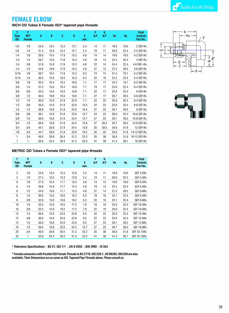
Double Ferrule Fittings Double Ferrule Fittings
14
BULKHEAD UNIONINCH OD Tubes
T Panel Max. FluidTube A Ax C D E F G H Hx Hole Panel ControlsOD min. A/F A/F Drill Thick- Part No.
Size ness
1/16 31.5 17.3 11.0 8.6 1.3 11 8 23.8 13.5 5.2 3.0 1 SCB
1/8 51.3 31.2 15.3 12.7 2.4 11 11 38.1 24.6 8.3 12.7 2 SCB
1/4 57.6 33.6 17.8 15.3 4.8 16 14 43.0 26.2 11.5 10.1 4 SCB
5/16 60.7 35.8 18.5 16.3 6.3 17 16 46.0 28.5 13.0 11.1 5 SCB
3/8 62.2 36.8 19.3 7.1 7.1 22 17 47.5 29.5 14.6 11.1 6 SCB
1/2 71.1 41.9 21.8 22.9 10.4 24 22 50.8 31.8 19.5 12.7 8 SCB
5/8 72.6 42.7 21.8 24.4 12.7 27 25 52.3 32.5 22.6 12.7 10 SCB
3/4 79.0 47.5 21.8 24.4 16.0 30 28.5 58.6 37.4 25.8 16.8 12 SCB
1 95.6 57.4 26.4 31.2 22.3 35 38 71.3 45.2 33.7 19.0 16 SCB
1.1/4 123.2 69.9 38.9 41.2 27.6 50 50 79.0 47.7 41.6 19.0 20 SCB
1.1/2 139.2 76.4 45.2 50.0 34.0 60 57 84.8 49.3 49.6 19.0 24 SCB
2 180.4 93.7 62.7 67.6 46.0 70 76 105.6 56.4 67.0 19.0 32 SCB
METRIC OD Tubes
T Panel Max. FluidTube A Ax C D E F G H Hx Hole Panel ControlsOD min. A/F A/F Drill Thick- Part No.
Size ness
3 51.3 31.2 15.3 12.9 2.4 14 11 38.1 24.6 8.3 12.7 SCB-3
6 57.7 33.6 17.7 15.3 4.8 16 14 42.9 26.2 11.5 10.2 SCB-6
8 61.0 36.1 18.6 16.2 6.3 17 16 46.0 28.6 13.1 11.2 SCB-8
10 63.7 37.0 19.5 17.2 7.9 22 19 48.5 29.4 16.3 11.2 SCB-10
12 71.0 41.9 22.0 22.8 9.5 24 22 50.8 31.8 19.5 12.7 SCB-12
14 72.5 42.6 22.0 24.4 11.1 27 25 52.3 32.5 22.5 12.7 SCB-14
15 72.5 42.6 22.0 24.4 11.9 27 25 52.3 32.5 22.8 12.7 SCB-15
16 72.5 42.6 22.0 24.4 12.7 27 25 52.3 32.5 22.8 12.7 SCB-16
18 78.9 47.4 22.0 24.4 15.1 30 30 58.7 37.3 26.0 16.8 SCB-18
20 84.5 53.0 22.0 26.0 15.8 35 32 64.3 42.9 29.0 19.0 SCB-20
25 95.6 57.4 26.4 31.2 22.3 35 38 71.3 45.2 33.7 19.0 SCB-25
30 123.7 70.2 39.2 39.6 26.2 50 46 80.5 48.6 40.5 19.0 SCB-30
32 128.3 72.5 41.6 42.0 27.6 50 50 82.3 49.5 42.5 19.0 SCB-32
38 144.6 79.1 47.9 49.4 33.7 60 57 89.4 51.5 50.5 19.0 SCB-38
BULKHEAD REDUCING UNIONINCH OD Tubes
T T Panel Max. FluidTube Tube A Ax Cx D Dx E F G Gx H Hx Hole Panel ControlsOD OD min. A/F A/F A/F Drill Thick- Part No.
Size ness
1/4 1/8 55.2 33.5 15.3 15.3 12.7 2.4 16 14 11 41.2 26.2 11.5 10.2 4-2 SCRB
3/8 1/4 60.7 36.6 17.8 16.8 15.3 4.8 22 17 14 46.0 29.5 14.6 11.2 6-4 SCRB
1/2 1/4 66.8 41.9 17.8 22.4 15.3 4.8 24 22 14 49.2 31.8 19.5 12.7 8-4 SCRB
1/2 3/8 66.8 41.9 17.8 22.4 16.8 7.1 24 22 17 49.2 31.8 19.5 12.7 8-6 SCRB
METRIC OD Tubes
T T Panel Max. FluidTube Tube A Ax Cx D Dx E F G Gx H Hx Hole Panel ControlsOD OD min. A/F A/F A/F Drill Thick- Part No.
Size ness
6 3 56.0 33.6 17.7 15.3 12.9 2.4 16 14 11 41.2 26.2 11.5 10.2 SCRB-6-3
8 6 61.0 36.1 18.6 16.2 15.3 4.8 17 16 14 48.0 28.6 13.1 11.2 SCRB-8-6
10 6 63.7 37.0 19.5 17.2 15.3 4.8 22 19 14 48.5 29.4 16.3 11.2 SCRB-10-6
12 6 71.0 41.9 22.0 22.8 15.3 4.8 24 22 14 50.8 31.8 19.5 12.7 SCRB-12-6
12 10 71.0 41.9 22.0 22.8 17.2 7.9 24 22 17 50.8 31.8 19.5 12.7 SCRB-12-10
FEMALE ELBOW INCH OD Tubes X Female ISO* tapered pipe threads
T P F G FluidTube NPT A B C D E A/F A/F Hx Hy ControlsOD Female min. Part No.
1/8 1/8 24.6 10.4 15.3 12.7 2.4 14 11 18.0 19.0 2 SEF-Rx
1/8 1/4 27.4 15.0 15.3 12.7 2.4 19 11 20.8 22.4 2-4 SEF-Rx
1/4 1/8 26.9 10.4 17.8 15.3 4.8 14 14 19.6 19.0 4-2 SEF-Rx
1/4 1/4 29.7 15.0 17.8 15.3 4.8 19 14 22.4 22.4 4 SEF-Rx
1/4 3/8 31.8 15.0 17.8 15.3 4.8 22 14 24.4 22.4 4-6 SEF--Rx
1/4 1/2 34.6 19.8 17.8 15.3 4.8 27 14 27.2 28.5 4-8 SEF-Rx
5/16 1/8 28.7 10.4 17.8 15.3 6.3 19 14 21.4 19.1 5-2 SEF-Rx
5/16 1/4 30.5 15.0 18.5 16.3 6.3 22 16 23.2 22.4 5-4 SEF-Rx
3/8 1/8 30.5 10.4 19.3 16.8 7.1 17 17 23.2 19.1 6-2 SEF-Rx
3/8 1/4 31.2 15.0 19.3 16.8 7.1 19 17 23.9 22.4 6-4 SEF-Rx
3/8 3/8 33.3 15.0 19.3 16.8 7.1 22 17 25.9 22.4 6 SEF-Rx
3/8 1/2 36.0 19.8 19.3 16.8 7.1 27 17 28.7 28.5 6-8 SEF-Rx
1/2 1/4 36.0 15.0 21.8 22.9 7.1 22 22 25.9 22.4 8-4 SEF-Rx
1/2 3/8 36.0 15.0 21.8 22.9 10.4 22 22 25.9 22.4 8-6 SEF-Rx
1/2 1/2 38.9 19.8 21.8 22.9 10.4 27 22 28.7 28.5 8 SEF-Rx
5/8 3/8 38.1 15.0 21.8 22.9 12.7 24 22 28.0 22.4 10-6 SEF-Rx
5/8 1/2 39.9 19.8 21.8 24.4 12.7 27 25 29.7 28.5 10-8 SEF-Rx
3/4 1/2 39.9 19.8 21.8 24.4 15.8 27 28.5 29.7 28.5 12-8 SEF-Rx
3/4 3/4 44.7 20.6 21.8 24.4 15.8 35 28.5 34.6 31.8 12 SEF-Rx
7/8 3/4 44.7 20.6 21.8 25.9 18.2 35 32 34.6 31.8 14-12 SEF-Rx
1 3/4 49.0 20.6 26.4 31.2 22.3 35 38 36.8 31.8 16-12 SEF-Rx
1 1 53.6 25.4 26.4 31.2 22.3 41 38 41.4 38.1 16 SEF-Rx
METRIC OD Tubes x Female ISO* tapered pipe threads
T P F G FluidTube NPT A B C D E A/F A/F Hx Hy ControlsOD Female min. Part No.
3 1/8 24.6 10.4 15.3 12.9 2.4 14 11 18.0 19.0 SEF 3-2Rx
3 1/4 27.4 15.0 15.3 12.9 2.4 19 11 20.8 22.4 SEF 3-4Rx
6 1/8 27.0 10.4 17.7 15.3 4.8 14 14 19.6 19.0 SEF 6-2Rx
6 1/4 29.8 15.0 17.7 15.3 4.8 19 14 22.4 22.4 SCF 6-4Rx
6 1/2 34.6 19.8 17.7 15.3 4.8 27 14 27.2 28.5 SEF 6-8Rx
8 1/4 30.6 15.0 18.6 16.2 6.3 19 16 23.1 22.4 SEF 8-4Rx
8 3/8 32.6 15.0 18.6 16.2 6.3 22 16 25.1 22.4 SEF 8-6Rx
10 1/4 33.5 15.0 19.5 17.2 7.9 19 19 25.9 22.4 SEF 10-4Rx
10 3/8 33.5 15.0 19.5 17.2 7.9 22 19 25.9 22.4 SEF 10-6Rx
12 1/4 36.0 15.0 22.0 22.8 9.5 22 22 25.9 22.4 SEF 12-4Rx
12 3/8 36.0 15.0 22.0 22.8 9.5 22 22 25.9 22.4 SEF 12-6Rx
12 1/2 38.8 19.8 22.0 22.8 9.5 27 22 28.7 28.5 SEF 12-8Rx
16 1/2 39.5 19.8 22.0 24.4 12.7 27 25 29.7 28.5 SEF 16-8Rx
25 3/4 49.0 20.6 26.5 31.3 22.3 35 38 36.8 31.8 SEF 25-12Rx
25 1 53.6 25.4 26.5 31.3 22.3 41 38 41.4 38.1 SEF 25-16Rx
39
NOTE: The combinations shown above are representative of various possibilities. Other combinations not shown are also available. Please consult us.
* Reference Specifications : BS 21: ISO 7/1 : JIS B 0203 : DIN 2999 : IS 554
* Female connectors with Parallel ISO Female Threads to BS:2779; ISO 228/1; JIS B6202; DIN 259 are also available. Their Dimensions are as same as ISO. Tapered Pipe Threads above. Pleae consult us.

Double Ferrule Fittings Double Ferrule Fittings
13
REDUCING UNION INCH OD Tubes
T Tx FluidTube Tube A C Cx D Dx E F G Gx H ControlsOD OD min. A/F A/F A/F Part No.
1/4 1/8 38.6 17.8 15.3 15.3 12.7 2.4 14 14 11 24.6 4-2 SCR
5/16 1/8 39.6 18.6 15.3 16.3 12.7 2.4 14 16 11 25.7 5-2 SCR
5/16 1/4 42.2 18.6 17.8 16.3 15.3 4.8 14 16 14 27.5 5-4 SCR
3/8 1/8 40.9 19.3 15.3 16.8 12.7 2.4 16 17 11 26.9 6-2 SCR
3/8 1/4 43.2 19.3 17.8 16.8 15.3 4.8 16 17 14 28.5 6-4 SCR
1/2 1/8 45.2 21.8 15.3 22.9 12.7 2.4 22 22 11 28.5 8-2 SCR
1/2 1/4 47.0 21.8 17.8 22.9 15.3 4.8 22 22 14 29.5 8-4 SCR
1/2 3/8 48.5 21.8 19.3 22.9 16.8 7.1 22 22 17 31.0 8-6 SCR
5/8 3/8 49.3 21.8 19.3 24.4 16.8 7.1 24 25 17 31.8 10-6 SCR
5/8 1/2 52.0 21.8 21.8 24.4 22.9 10.4 24 25 22 31.8 10-8 SCR
3/4 1/4 49.3 21.8 17.8 24.4 15.3 4.8 27 28.5 14 31.8 12-4 SCR
3/4 3/8 50.8 21.8 19.3 24.4 16.8 7.1 27 28.5 17 33.3 12-6 SCR
3/4 1/2 53.6 21.8 21.8 24.4 22.9 10.4 27 28.5 22 33.3 12-8 SCR
1 1/2 60.5 26.5 21.8 31.2 22.9 10.4 35 38 22 38.1 16-8 SCR
1 3/4 60.5 26.5 21.8 31.2 24.4 15.8 35 38 28.5 38.1 16-12 SCR
1.1/4 1 92.2 38.9 26.4 41.2 31.2 22.3 45 50 38 48.0 20-16 SCR
1.1/2 1.1/4 60.5 26.5 21.8 31.2 24.4 15.8 55 57 50 53.6 24-20 SCR
METRIC OD Tubes
T Tx FluidTube Tube A C Cx D Dx E F G Gx H ControlsOD OD min. A/F A/F A/F Part No.
6 3 38.6 17.7 15.3 15.3 12.9 2.4 14 14 11 24.6 SCR 6-3
8 6 42.3 18.6 17.7 16.2 15.3 4.8 14 16 14 27.4 SCR 8-6
10 6 44.5 19.5 17.7 17.2 15.3 4.8 17 19 14 29.5 SCR 10-6
10 8 45.1 19.5 18.6 17.2 16.2 6.3 17 19 16 30.0 SCR 10-8
12 6 47.0 22.0 17.7 22.8 15.3 4.8 22 22 14 29.5 SCR 12-6
12 8 47.8 22.0 18.6 22.8 16.2 6.4 22 22 16 30.2 SCR 12-8
12 10 48.7 22.0 19.5 22.8 17.2 7.9 22 22 19 31.0 SCR 12-10
16 10 49.5 22.0 19.5 24.4 17.2 7.9 24 25 19 31.8 SCR 16-10
16 12 52.0 22.0 22.0 24.4 22.8 9.5 24 25 22 31.8 SCR 16-12
22 18 55.0 22.0 22.0 26.0 24.4 15.1 30 32 30 34.8 SCR 22-18
22 20 55.0 22.0 22.0 26.0 26.6 15.9 30 32 32 34.8 SCR 22-20
25 12 65.0 26.5 22.0 31.3 22.8 9.5 35 38 22 40.4 SCR 25-12
25 20 65.0 26.5 22.0 31.3 26.0 15.9 35 38 32 40.4 SCR 25-20
30 20 75.4 39.2 22.0 39.6 26.0 15.9 45 50 32 43.7 SCR 30-20
30 25 80.1 39.2 26.5 39.6 31.3 21.8 45 50 38 46.2 SCR 30-25
32 20 77.8 41.6 22.0 42.0 26.0 15.9 45 50 32 44.7 SCR 32-20
32 25 82.3 41.6 26.5 42.0 31.3 21.8 45 50 38 47.0 SCR 32-25
38 20 92.0 47.9 26.5 49.4 31.3 21.8 55 57 38 52.1 SCR 38-20
38 25 104.6 47.9 39.2 49.4 39.6 26.2 55 57 50 55.4 SCR 38-25
FEMALE BRANCH TEE INCH OD Tubes X Female NPT Threads
T P F G FluidTube NPT A Ax B C D E A/F A/F H Hx Hy ControlsOD Female min. Part No.
1/8 1/8 49.2 24.6 10.4 15.3 12.7 2.4 14 11 36.0 18.0 19.0 2 STBF-N
1/4 1/8 53.8 26.9 10.4 17.8 15.3 4.8 14 14 39.2 19.6 19.0 4-2 STBF-N
1/4 1/4 59.4 27.9 15.0 17.8 15.3 4.8 19 14 44.8 22.4 22.4 4 STBF-N
3/8 1/4 62.4 31.2 15.0 19.3 16.8 7.1 16 16 47.8 23.9 22.4 6-4 STBF-N
3/8 3/8 66.6 33.3 15.0 19.3 16.8 7.1 19 16 51.8 25.9 22.4 6 STBF-N
1/2 3/8 72.0 36.0 15.0 21.8 22.9 10.4 19 19 51.8 25.9 22.4 8-6 STBF-N
1/2 1/2 77.8 38.9 19.8 21.8 22.9 10.4 22 22 57.4 28.7 28.5 8 STBF-N
3/4 3/4 89.4 44.7 20.6 21.8 24.4 15.8 35 22 69.2 34.6 31.8 12 STBF-N
1 3/4 98.0 49.0 20.6 26.4 31.2 22.3 35 25 73.6 36.8 31.8 16-12 STBF-N
1 1 107.2 53.6 25.4 26.4 31.2 22.3 41 38 82.8 41.4 38.1 16 STBF-6N
METRIC Tubes X Female NPT Threads
T P F G FluidTube NPT A Ax B C D E A/F A/F H Hx Hy ControlsOD Female min. Part No.
3 1/8 49.2 24.6 10.4 15.3 12.9 2.4 14 11 36.0 18.0 19.0 STBF 3-2N
6 1/8 54.0 27.0 10.4 17.7 15.3 4.8 14 14 39.2 19.6 19.0 STBF 6-2N
6 1/4 59.6 29.8 15.0 17.7 15.3 4.8 19 14 44.8 22.4 22.4 STBF 6-4N
8 1/8 59.8 29.9 10.4 18.6 16.2 6.3 16 16 44.8 22.4 19.0 STBF 8-2N
8 1/4 61.2 30.6 15.0 18.6 16.2 6.3 19 16 46.2 23.1 22.4 STBF 8-4N
10 1/4 67.0 33.5 15.0 19.5 17.2 7.9 19 19 51.8 25.9 22.4 STBF 10-4N
12 3/8 72.0 36.0 15.0 22.0 22.8 9.5 22 22 51.8 25.9 22.4 STBF 12-6N
12 1/2 77.6 38.8 19.8 22.0 22.8 9.5 27 22 57.4 28.7 28.5 STBF 12-8N
16 1/2 79.0 39.5 19.8 22.0 24.4 12.7 27 25 59.4 29.7 28.5 STBF 16-8N
25 1 107.2 53.6 25.4 26.5 31.3 22.3 41 38 82.8 41.4 38.1 STBF 25-16N
FEMALE RUN TEE INCH OD Tubes X Female NPT Threads
T P F G FluidTube NPT A Ax B C D E A/F A/F H Hx Hy ControlsOD Female min. Part No.
1/8 1/8 43.6 24.6 10.4 15.3 12.7 2.4 14 11 37.0 18.0 19.0 2 STRF-N
1/4 1/8 45.9 26.9 10.4 17.8 15.3 4.8 14 14 38.6 19.6 19.0 4-2 STRF-N
1/4 1/4 52.1 29.7 15.0 17.8 15.3 4.8 19 14 44.8 22.4 22.4 4 STRF-N
3/8 1/4 53.6 31.2 15.0 19.3 16.8 7.1 19 17 46.3 23.9 22.4 6-4 STRF-N
3/8 3/8 55.7 33.3 15.0 19.3 16.8 7.1 22 17 48.3 25.9 22.4 6 STRF-N
1/2 3/8 58.4 36.0 15.0 21.8 22.9 10.4 22 22 48.3 25.9 22.4 8-6 STRF-N
1/2 1/2 67.4 38.9 19.8 21.8 22.9 10.4 27 22 57.2 28.7 28.5 8 STRF-N
3/4 3/4 76.5 44.7 20.6 21.8 24.4 15.8 35 29 66.4 34.6 31.8 12 STRF-N
1 3/4 80.8 49.0 20.6 26.4 31 22.3 35 38 68.6 36.8 31.8 16-12 STRF-N
1 1 91.7 53.6 25.4 26.4 31 22.3 41 38 79.5 41.4 38.1 16 STRF-N
METRIC OD Tubes X Female NPT Threads
T P F G FluidTube NPT A Ax B C D E A/F A/F H Hx Hy ControlsOD Female min. Part No.
3 1/8 43.6 24.6 10.4 15.3 12.9 2.4 14 11 37.0 18.0 19.0 STRF 3-2N
6 1/8 46.0 27.0 10.4 17.7 15.3 4.8 14 14 38.6 19.6 19.0 STRF 6-2N
6 1/4 52.2 29.8 15.0 17.7 15.3 4.8 19 14 44.8 22.4 22.4 STRF 6-4N
8 1/8 48.9 29.9 10.4 18.6 16.2 6.3 16 16 41.4 22.4 19.0 STRF 8-2N
8 1/4 53.0 30.6 15.0 18.6 16.2 6.3 19 16 45.5 23.1 22.4 STRF 8-4N
10 1/4 55.9 33.5 15.0 19.5 17.2 7.9 19 19 48.3 25.9 22.4 STRF 10-4N
12 3/8 58.4 36.0 15.0 22.0 22.8 9.5 22 22 48.3 25.9 22.4 STRF 12-6N
12 1/2 67.3 38.8 19.8 22.0 22.8 9.5 27 22 57.2 28.7 28.5 STRF 12-8N
16 1/2 68.0 39.5 19.8 22.0 24 12.7 27 25 58.2 29.7 28.5 STRF 16-8N
25 1 91.7 53.6 25.4 26.5 31.3 22.3 41 38 79.5 41.4 38.1 STRF 25-16N
40
NOTE: The combinations shown above are representative of various possibilities. Other combinations not shown are also available. Please consult us.
NOTE: Bulkhead Female Connectors are also available with ISO Taper Female Threads, ISO Parallel Female Threads and ISO Female Marcometer connection. Please consult us.
NOTE: The combinations shown above are representative of various possibilities. Other combinations not shown are also available. Please consult us.

Double Ferrule Fittings Double Ferrule Fittings
12 41
BUTT WELD PIPE CONNECTORINCH OD Tubes to Pipe*
T Pipe Fluid Tube Weld A B C D E F G H J ControlsOD Male min. A/F A/F Part No.
1/8 1/8 30.5 9.6 15.3 12.7 2.4 11 11 23.9 10.3 2 SC-NB BW
1/4 1/8 32.8 9.6 17.8 15.3 4.8 14 14 25.4 10.3 4-2 CS-NB BW
1/4 1/4 37.8 14.3 17.8 15.3 4.8 14 14 30.5 13.7 4 SC-NB BW
5/16 1/8 34.0 9.6 18.5 16.3 5.1 14 16 26.7 10.3 5-2 SC-NB BW
5/16 1/4 38.6 14.3 18.5 16.3 6.3 16 16 31.2 13.7 5-4 SC-NB BW
3/8 1/4 39.9 14.3 19.3 16.8 7.1 16 17 32.5 13.7 6-4 SC-NB BW
3/8 3/8 39.9 14.3 19.3 16.8 7.1 17 17 32.5 17.2 6 SC-NB BW
3/8 1/2 46.3 19.1 19.3 16.8 7.1 22 17 38.9 21.3 6-8 SC-NB BW
1/2 3/8 43.4 14.3 21.8 22.9 10.4 22 22 33.3 17.2 8-6 SC-NB BW
1/2 1/2 49.0 19.1 21.8 22.9 10.4 22 22 38.9 21.3 8 SC-NB BW
1/2 3/4 50.5 19.1 21.8 22.9 10.4 27 22 40.4 26.7 8-12 SC-NB BW
5/8 1/2 49.0 19.1 21.8 24.4 12.7 24 25 38.9 21.3 10-8 SC-NB BW
3/4 3/4 50.5 19.1 21.8 24.4 15.8 27 29 40.4 26.7 12 SC-NB BW
1 1 62.2 23.8 26.4 31.2 22.3 35 38 50.0 33.4 16 SC-NB BW
1.1/4 1.1/4 77.2 23.8 38.9 41.2 27.6 46 50 55.2 42.2 20 SC-NB BW
1.1/2 1.1/2 88.9 26.2 45.2 50.0 34 55 60 61.7 48.3 24 SC-NB BW
METRIC OD Tubes to Pipe*
T Pipe Fluid Tube Weld A B C D E F G H J ControlsOD Male min. A/F A/F Part No.
3 1/8 30.5 9.6 15.3 12.9 2.4 11 11 23.9 10.3 SC-NB BW-3-2
6 1/8 32.8 9.6 17.8 15.3 4.8 14 14 25.4 10.3 SC-NB BW-6-2
6 1/4 37.9 14.3 17.8 15.3 4.8 14 14 30.5 13.7 SC-NB BW-6-4
8 1/8 34.2 9.6 18.5 16.3 5.1 16 16 26.7 10.3 SC-NB BW-8-2
8 1/4 38.7 14.3 18.5 16.3 6.3 16 16 31.2 13.7 SC-NB BW-8-4
8 1/2 45.6 19.1 18.5 16.3 6.3 22 16 38.1 21.3 SC-NB BW-8
10 1/4 40.9 14.3 19.5 17.2 7.1 19 19 33.3 13.7 SC-NB BW-10-4
10 3/8 40.9 14.3 19.5 17.2 7.9 19 19 33.3 17.2 SC- NB BW-10-6
10 1/2 46.5 19.1 19.5 17.2 7.9 22 19 38.9 21.3 SC-NB BW-10-8
12 1/4 43.4 14.3 22.0 22.9 7.1 22 22 33.3 13.7 SC-NB BW-12-4
12 3/8 43.4 14.3 22.0 22.9 9.5 22 22 33.3 17.2 SC-NB BW-12-6
12 1/2 49.0 19.1 22.0 22.9 9.5 22 22 38.9 21.3 SC-NB BW-12
16 1/2 49.0 19.1 22.0 24.4 12.7 24 25 38.9 21.3 SC-NB BW-16-8
20 3/4 52.3 19.1 22.0 26 15.9 30 32 42.2 26.7 SC-NB BW-20-12
22 3/4 52.3 19.1 22.0 26 15.9 30 32 42.2 26.7 SC-NB BW-22-12
25 1 62.3 23.8 26.5 31.3 21.8 35 38 50.0 33.4 SC-NB BW-25-16
30 1.1/4 77.2 23.8 39.2 39.6 26.2 45 50 55.6 42.2 SC-NB BW-30-20
32 1.1/4 79.6 23.8 41.6 42.0 28.6 45 50 56.6 42.2 SC-NB BW-32-20
38 1.1/2 91.6 26.2 47.9 49.4 33.7 55 57 64.0 48.3 SC-NB BW-38-24
BUTT WELD PIPE ELBOW INCH OD Tubes to Pipe*
T Pipe Fluid Tube Weld A B C D E F G Hx Hy J ControlsOD Male min. A/F A/F Part No.
1/4 1/8 27.0 9.6 17.8 15.3 4.8 14 14 19.6 18.8 10.3 4-2 SE-NB BW
1/4 1/4 27.0 14.3 17.8 15.3 4.8 14 14 19.6 23.4 13.7 4 SE-NB BW
3/8 1/4 30.5 14.3 19.3 16.8 7.1 16 17 23.1 25.9 13.7 6-4 SE-NB BW
1/2 1/2 36.0 19.1 21.8 22.9 10.4 22 22 25.9 33.0 21.3 8 SE-NB BW
3/4 3/4 39.9 19.1 21.8 24.4 15.8 27 29 29.7 36.8 26.7 12 SE-NB BW
1 1 49.0 23.8 26.4 31.2 22.3 35 38 36.8 46.5 33.4 16 SE-NB BW
1.1/4 1.1/4 66.5 23.8 38.9 41.2 27.6 45 50 44.5 47.8 42.2 20 SE-NB BW
1.1/2 1.1/2 78.0 26.2 45.2 50.0 34.0 50 57 50.8 60.5 48.3 24 SE-NB
* Reference specification : ANSI B36.19, BS:1387, DIN2391, IS:1239
12
INCH OD Tubes
T FluidTube A C D E F G H ControlsOD min. A/F A/F Part No.
1/16 25.1 11.0 8.6 1.3 8 8 17.5 1 SC
1/8 35.6 15.3 12.7 2.4 11 11 22.4 2 SC
1/4 40.9 17.8 15.3 4.8 14 14 26.2 4 SC
5/16 42.9 18.5 16.3 6.3 14 16 28.2 5 SC
3/8 45.0 19.3 16.8 7.1 16 17 30.2 6 SC
1/2 51.3 21.8 22.9 10.4 22 22 31.0 8 SC
5/8 52.0 21.8 24.4 12.7 24 25 31.8 10 SC
3/4 53.6 21.8 24.4 15.8 27 28.5 33.3 12 SC
7/8 55.2 21.8 25.9 18.2 30 32 34.8 14 SC
1 64.8 26.4 31.2 22.3 35 38 40.4 16 SC
1.1/4 92.2 38.9 41.2 27.6 46 50 48.0 20 SC
1.1/2 108.0 45.2 50.0 34.0 55 57 53.6 24 SC
2 149.4 62.7 67.6 46.0 70 76 74.7 32 SC
METRIC OD Tubes
T FluidTube A C D E F G H ControlsOD min. A/F A/F Part No.
3 35.3 15.3 12.9 2.4 11 11 22.1 SC-3
6 41.0 17.7 15.3 4.8 14 14 26.2 SC-6
8 43.2 18.6 16.2 6.3 16 16 28.2 SC-8
10 46.2 19.5 17.2 7.9 17 19 31.0 SC-10
12 51.2 22.0 22.8 9.5 22 22 31.0 SC-12
14 52.0 22.0 24.4 11.1 24 25 31.0 SC-14
15 52.0 22.0 24.4 11.9 24 25 31.8 SC-15
16 52.0 22.0 24.4 12.7 24 25 31.8 SC-16
18 53.5 22.0 24.4 15.1 27 30 33.3 SC-18
20 55.0 22.0 26.0 15.9 30 32 34.8 SC-20
22 55.0 22.0 26.0 18.3 30 32 34.8 SC-22
25 65.0 26.5 31.3 21.8 35 38 40.4 SC-25
28 85.0 36.6 36.6 21.8 41 46 43.4 SC-28
30 92.7 39.2 39.6 26.2 46 50 49.5 SC-30
32 97.3 41.6 42.0 28.6 46 50 51.3 SC-32
38 113.6 47.9 49.4 33.7 55 57 58.4 SC-38
UNION

FITTING END CLOSUREINCH OD Tubes METRIC OD Tubes
T Fluid T FluidTube G Controls Tube G ControlsOD A/F Part No. OD A/F Part No.
1/16 8 1 SFC 3 11 SFC-3
1/8 11 2 SFC 6 14 SFC-6
1/4 14 4 SFC 8 16 SFC-8
5/16 16 5 SFC 10 19 SFC-10
3/8 17 6 SFC 12 22 SFC-12
1/2 22 8 SFC 14 25 SFC-14
5/8 25 10 SFC 15 25 SFC-15
3/4 28.5 12 SFC 16 25 SFC-16
7/8 32 14 SFC 18 30 SFC-18
1 38 16 SFC 20 32 SFC-20
1.1/4 50 20 SFC 22 32 SFC-22
1.1/2 57 24 SFC 25 38 SFC-25
2 76 32 SFC 28 46 SFC-28
30 50 SFC-30
32 50 SFC-32
38 57 SFC-38
Double Ferrule Fittings
42
Double Ferrule Fittings
11
INCH OD Tubes
T FluidTube A C D F G H Controls OD A/F A/F Part No.
1/16 13.0 11.0 8.6 11 8 11.2 1 SPC
1/8 20.0 15.3 12.7 11 11 13.5 2 SPC
1/4 23.4 17.8 15.3 14 14 16.0 4 SPC
5/16 24.4 18.5 16.3 16 16 17.0 5 SPC
3/8 25.7 19.3 16.8 17 17 18.3 6 SPC
1/2 29.2 21.8 22.9 22 22 19.0 8 SPC
5/8 30.0 21.8 24.4 24 25 19.8 10 SPC
3/4 31.5 21.8 24.4 27 28.5 21.4 12 SPC
7/8 34.0 21.8 25.9 35 32 23.9 14 SPC
1 38.4 26.4 31.2 35 38 26.2 16 SPC
1.1/4 53.3 38.9 41.2 46 50 31.2 20 SPC
1.1/2 64.5 45.2 50.0 55 57 37.4 24 SPC
2 88.6 62.7 67.6 70.0 76.0 49.3 32 SPC
METRIC OD Tubes
T FluidTube A C D F G H Controls OD A/F A/F Part No.
3 20.1 15.3 12.9 11 11 13.5 SPC-3
6 23.1 17.7 15.3 14 14 15.7 SPC-6
8 24.5 18.6 16.2 16 16 17.0 SPC-8
10 26.6 19.5 17.2 17 19 19.0 SPC-10
12 29.1 22.0 22.8 22 22 19.0 SPC-12
14 29.9 22.0 24.4 24 25 19.8 SPC-14
15 29.9 22.0 24.4 24 25 19.8 SPC-15
16 29.9 22.0 24.4 24 25 19.8 SPC-16
18 31.4 22.0 24.4 27 30 21.3 SPC-18
20 34.0 22.0 26.0 32 32 23.9 SPC-20
22 34.0 22.0 26.0 32 32 23.9 SPC-22
25 38.5 26.5 31.3 35 38 26.2 SPC-25
28 48.5 36.6 36.6 41 46 27.7 SPC-28
30 53.4 39.2 39.6 46 50 31.8 SPC-30
32 55.8 41.6 42.0 46 50 32.8 SPC-32
38 65.4 47.9 49.4 55 57 37.8 SPC-38
TUBE END CLOSURESOCKET WELD TUBE CONNECTOR
SOCKET WELD TUBE ELBOW
INCH OD Tubes
T F G FluidTube A B Bx C D E A/F A/F H J ControlsOD min. Part No.
1/8 29.0 8.6 6.4 15.3 12.7 2.4 11 11 22.9 7.9 2 SC- SW
1/4 33.5 10.4 7.9 17.8 5.3 4.8 14 14 26.2 11.2 4 SC- SW
3/8 37.6 12.0 9.6 19.3 16.8 7.1 16 17 30.3 15.8 6 SC- SW
1/2 41.2 12.0 12.7 21.8 22.9 10.4 22 22 31.0 19.1 8 SC- SW
3/4 43.4 12.0 14.3 21.8 24.4 15.8 27 28.5 33.3 26.7 12 SC- SW
1 52.6 14.3 19.1 26.4 31.2 22.3 35 38 40.4 33.3 16 SC- SW
1.1/4 72.4 19.1 19.1 38.9 41.2 27.6 45 50 50.3 42.0 20 SC- SW
1.1/2 81.8 19.1 23.8 45.2 50.0 34.0 55 57 54.6 50.0 24 SC- SW
METRIC OD Tubes
T F G FluidTube A B Bx C D E A/F A/F H J ControlsOD min. Part No.
3 29.0 8.6 6.4 15.3 12.9 2.4 11 11 22.9 7.9 SC-3- SW
6 33.5 10.4 7.9 17.7 15.3 4.8 14 14 26.2 11.2 SC-6- SW
10 37.6 12.0 9.6 19.5 17.2 7.1 16 17 30.3 15.8 SC-10- SW
12 41.2 12.0 12.7 22.0 22.8 10.4 22 22 31.0 19.1 SC-12- SW
20 43.4 12.0 14.3 22.0 26.0 15.8 27 28.5 33.3 26.7 SC-20- SW
25 52.6 14.3 19.1 26.5 31.3 22.3 35 38 40.4 33.3 SC-25- SW
32 72.4 19.1 19.1 41.6 42.0 27.6 45 50 50.3 42.0 SC-32- SW
38 81.8 19.1 23.8 47.9 49.4 34.0 55 57 54.6 50.0 SC-38- SW
INCH OD Tubes
T F G FluidTube A Bx C D E A/F A/F Hx Hy K ControlsOD min. Part No.
1/4 27.0 7.9 17.8 15.3 4.8 14 14 19.6 19.6 12.7 4 SE- SW
3/8 30.5 9.6 19.3 16.8 7.1 16 17 23.1 23.1 15.8 6 SE- SW
1/2 36.0 12.7 21.8 22.9 10.4 22 22 25.9 25.9 20.6 8 SE- SW
34 39.9 14.3 21.8 24.4 15.8 27 28.5 29.7 29.7 27.0 12 SE- SW
1 49.0 19.1 26.4 31.2 22.3 35 38 36.8 36.8 35.0 16 SE- SW
1.1/4 66.5 19.1 38.9 41.2 27.6 45 50 44.5 47.8 43.0 20 SE- SW
1.1/2 78.0 23.8 45.2 50.0 34.0 50 57 50.8 60.4 48.0 24 SE- SW
METRIC OD Tubes
T F G FluidTube A B Bx C D E A/F A/F H J ControlsOD min. Part No.
6 27.0 7.9 17.7 15.3 4.8 14 14 19.6 19.6 12.7 SE-6- SW
10 30.5 9.6 19.5 17.2 7.1 16 17 23.1 23.1 15.8 SE-10- SW
12 36.0 12.7 22.0 22.8 10.4 22 22 25.9 25.9 20.6 SE-12- SW
20 39.9 14.3 22.0 26.0 15.8 27 28.5 29.7 29.7 27.0 SE-20- SW
25 49.0 19.1 26.5 31.3 22.3 35 38 36.8 36.8 35.0 SE-25- SW
32 66.5 19.1 41.6 42.0 27.6 45 50 44.5 47.8 43.0 SE-32- SW
38 78.0 23.8 47.9 49.4 34.0 50 57 50.8 60.4 48.0 SE-38- SW
NOTE: Available with socket welded connection for pipes.
NOTE: Socket weld Tube-to-pipe connections for inch and metric OD tubes to socket weld connections for pipes to ANSI B39.19, BS:1387, DIN:239, IS:1239 also available. Please consult us.
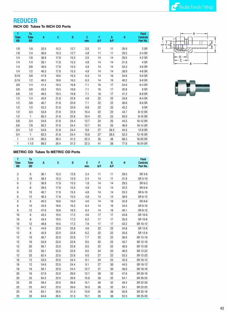
10
Double Ferrule Fittings
COUPLING CAPINCH OD Tubes METRIC OD tubes
T Fluid T FluidTube L G Controls Tube L G ControlsOD A/F Part No. OD A/F Part No.
1/16 8.0 8 1 Sn 3 12.0 11 Sn-3
1/8 12.0 11 2 Sn 6 12.7 14 Sn-6
1/4 12.7 14 4 Sn 8 13.5 16 Sn-8
5/16 14.0 16 5 Sn 10 15.1 19 Sn-10
3/8 14.5 17 6 Sn 12 17.5 22 Sn-12
1/2 17.5 22 8 Sn 14 17.5 25 Sn-14
5/8 17.5 25 10 Sn 15 17.5 25 Sn-15
3/4 17.5 28.5 12 Sn 16 17.5 25 Sn-16
7/8 17.5 32 14 Sn 18 17.5 30 Sn-18
1 20.6 38 16 Sn 20 17.5 32 Sn-20
1.1/4 31.8 50 20 Sn 22 17.5 32 Sn-22
1.1/2 38.0 57 24 Sn 25 20.6 38 Sn-25
2 52.5 76 32 Sn 28 30.6 46 Sn-28
30 32.7 50 Sn-30
32 31.8 50 Sn-32
38 38.1 57 Sn-38
INCH OD Tubes METRIC OD Tubes
T Fluid T FluidTube Controls Tube ControlsOD Part No. OD Part No.
1/16 1 ff 3 ff-3
1/8 2 ff 6 ff-6
1/4 4 ff 8 ff-8
5/16 5 ff 10 ff-10
3/8 6 ff 12 ff-12
1/2 8 ff 14 ff-14
5/8 10 ff 15 ff-15
3/4 12 ff 16 ff-16
7/8 14 ff 18 ff-18
1 16 ff 20 ff-20
1.1/4 20 ff 22 ff-22
1.1/2 24 ff 25 ff-25
2 32 ff 28 ff-28
30 ff-30
32 ff-32
38 ff-38
INCH OD Tubes METRIC OD Tubes
T Fluid T FluidTube Controls Tube ControlsOD Part No. OD Part No.
1/16 1 fb 3 fb-3
1/8 2 fb 6 fb-6
1/4 4 fb 8 fb-8
5/16 5 fb 10 fb-10
3/8 6 fb 12 fb-12
1/2 8 fb 14 fb-14
5/8 10 fb 15 fb-15
3/4 12 fb 16 fb-16
7/8 14 fb 18 fb-18
1 16 fb 20 fb-20
1.1/4 20 fb 22 fb-22
1.1/2 24 fb 25 fb-25
2 32 fb 28 fb-28
30 fb-30
32 fb-32
38 fb-38
FRONT FERRULE
BACK FERRULE
Double Ferrule Fittings
43
Double Ferrule Fittings
INCH OD Tubes To INCH OD Ports
T Tx FluidTube Tube A C D E F G H ControlsOD OD min. A/F A/F Part No.
1/8 1/8 33.5 15.3 12.7 2.0 11 11 26.9 2 SR
1/8 1/4 36.0 15.3 12.7 4.8 11 11 29.5 2-4 SR
1/4 1/8 36.8 17.8 15.3 2.0 14 14 29.5 4-2 SR
1/4 1/4 39.1 17.8 15.3 4.8 14 14 31.8 4 SR
1/4 3/8 40.6 17.8 15.3 4.8 14 14 33.3 4-6 SR
1/4 1/2 46.3 17.8 15.3 4.8 14 14 38.9 4-8 SR
5/16 3/8 41.9 18.6 16.3 6.3 14 16 34.6 5-6 SR
5/16 1/2 46.5 18.6 16.3 6.3 14 16 40.2 5-8 SR
3/8 1/4 41.4 19.3 16.8 7.1 16 17 34.0 6-4 SR
3/8 3/8 43.2 19.3 16.8 7.1 16 17 35.8 6 SR
3/8 1/2 48.5 19.3 16.8 7.1 16 17 41.2 6-8 SR
1/2 1/4 45.0 21.8 22.9 4.8 22 22 34.8 8-4 SR
1/2 3/8 46.7 21.8 22.9 7.1 22 22 36.6 8-6 SR
1/2 1/2 52.3 21.8 22.9 9.9 22 22 42.2 8 SR
1/2 3/4 53.8 21.8 22.9 10.4 22 22 43.7 8-12 SR
1/2 1 60.2 21.8 22.9 10.4 22 22 50.0 8-16 SR
5/8 3/4 54.6 21.8 24.4 12.7 24 25 44.5 10-12 SR
5/8 7/8 56.2 21.8 24.4 12.7 24 25 46.0 10-14 SR
3/4 1/2 54.6 21.8 24.4 9.9 27 28.5 44.5 12-8 SR
3/4 1 62.5 21.8 24.4 15.8 27 28.5 52.3 12-16 SR
1 1.1/4 80.5 26.4 31.2 22.3 35 38 68.3 16-20 SR
1 1.1/2 89.2 26.4 31.2 22.3 41 38 77.0 16-24 SR
METRIC OD Tubes To METRIC OD Ports
T Tx FluidTube Tube A C D E F G H ControlsOD OD min. A/F A/F Part No.
3 6 36.1 15.3 12.9 2.4 11 11 29.5 SR 3-6
3 10 38.4 15.3 12.9 2.4 14 11 31.8 SR 3-10
6 3 36.9 17.8 15.3 1.8 14 14 29.5 SR 6-3
6 8 39.9 17.8 15.3 4.8 14 14 32.5 SR 6-8
6 10 40.7 17.8 15.3 4.8 14 14 33.3 SR 6-10
6 12 46.3 17.8 15.3 4.8 14 14 38.9 SR 6-12
8 6 40.3 18.6 16.2 4.6 14 16 32.8 SR 8-6
8 10 42.0 18.6 16.2 6.4 14 16 34.5 SR 8-10
8 12 47.6 18.6 16.2 6.4 14 16 40.1 SR 8-12
10 6 42.4 19.5 17.2 4.6 17 17 34.8 SR 10-6
10 8 43.4 19.5 17.2 6.2 17 17 35.8 SR 10-8
10 12 49.8 19.5 17.2 7.9 17 17 42.2 SR 10-12
12 6 44.9 22.0 22.8 4.6 22 22 34.8 SR 12-6
12 8 45.9 22.0 22.8 6.2 22 22 35.8 SR 12-8
12 10 46.7 22.0 22.8 7.7 22 22 36.6 SR 12-10
12 16 53.8 22.0 22.8 9.5 22 22 43.7 SR 12-16
12 20 56.1 22.0 22.8 9.5 22 22 46.0 SR 12-20
12 22 56.1 22.0 22.8 9.5 24 22 46.0 SR 12-22
12 25 62.4 22.0 22.8 9.5 27 22 53.3 SR 12-25
16 12 53.0 22.0 24.4 9.1 24 25 42.9 SR 16-12
18 12 54.6 22.0 24.4 9.1 27 30 44.5 SR 18-12
18 16 56.1 22.0 24.4 12.7 27 30 46.0 SR 18-16
20 16 57.9 22.0 26.0 12.7 30 32 47.8 SR 20-16
20 25 64.2 22.0 26.0 15.8 30 32 54.1 SR 20-25
22 20 59.4 22.0 26.0 15.1 30 32 49.3 SR 22-20
22 25 64.2 22.0 26.0 18.3 30 32 54.1 SR 22-25
25 18 63.1 26.5 31.3 13.9 35 38 50.8 SR 25-18
25 20 64.6 26.5 31.3 15.1 35 38 52.3 SR 25-20
REDUCER
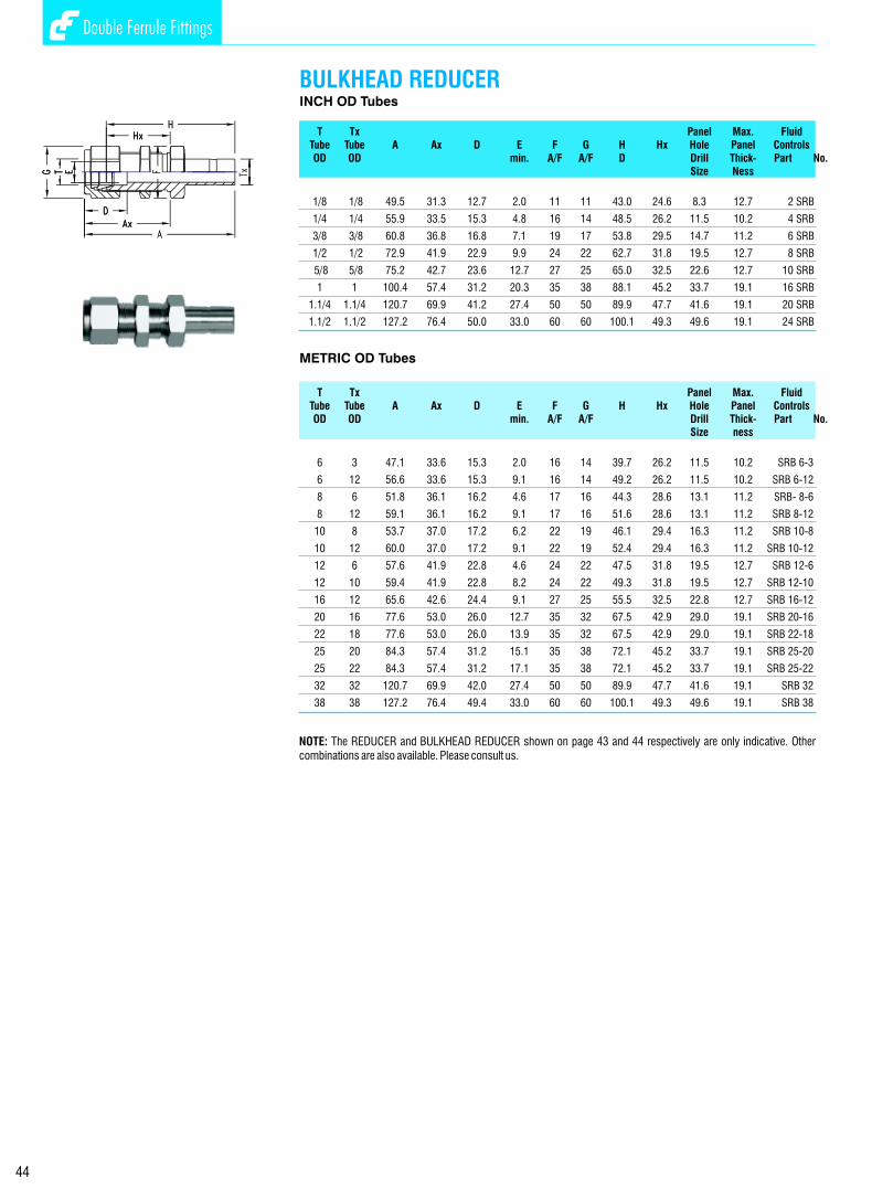
9
Double Ferrule Fittings
INCH OD Tubes
T Tx Panel Max. FluidTube Tube A Ax D E F G H Hx Hole Panel ControlsOD OD min. A/F A/F D Drill Thick- Part No.
Size Ness
1/8 1/8 49.5 31.3 12.7 2.0 11 11 43.0 24.6 8.3 12.7 2 SRB
1/4 1/4 55.9 33.5 15.3 4.8 16 14 48.5 26.2 11.5 10.2 4 SRB
3/8 3/8 60.8 36.8 16.8 7.1 19 17 53.8 29.5 14.7 11.2 6 SRB
1/2 1/2 72.9 41.9 22.9 9.9 24 22 62.7 31.8 19.5 12.7 8 SRB
5/8 5/8 75.2 42.7 23.6 12.7 27 25 65.0 32.5 22.6 12.7 10 SRB
1 1 100.4 57.4 31.2 20.3 35 38 88.1 45.2 33.7 19.1 16 SRB
1.1/4 1.1/4 120.7 69.9 41.2 27.4 50 50 89.9 47.7 41.6 19.1 20 SRB
1.1/2 1.1/2 127.2 76.4 50.0 33.0 60 60 100.1 49.3 49.6 19.1 24 SRB
METRIC OD Tubes
T Tx Panel Max. FluidTube Tube A Ax D E F G H Hx Hole Panel ControlsOD OD min. A/F A/F Drill Thick- Part No.
Size ness
6 3 47.1 33.6 15.3 2.0 16 14 39.7 26.2 11.5 10.2 SRB 6-3
6 12 56.6 33.6 15.3 9.1 16 14 49.2 26.2 11.5 10.2 SRB 6-12
8 6 51.8 36.1 16.2 4.6 17 16 44.3 28.6 13.1 11.2 SRB- 8-6
8 12 59.1 36.1 16.2 9.1 17 16 51.6 28.6 13.1 11.2 SRB 8-12
10 8 53.7 37.0 17.2 6.2 22 19 46.1 29.4 16.3 11.2 SRB 10-8
10 12 60.0 37.0 17.2 9.1 22 19 52.4 29.4 16.3 11.2 SRB 10-12
12 6 57.6 41.9 22.8 4.6 24 22 47.5 31.8 19.5 12.7 SRB 12-6
12 10 59.4 41.9 22.8 8.2 24 22 49.3 31.8 19.5 12.7 SRB 12-10
16 12 65.6 42.6 24.4 9.1 27 25 55.5 32.5 22.8 12.7 SRB 16-12
20 16 77.6 53.0 26.0 12.7 35 32 67.5 42.9 29.0 19.1 SRB 20-16
22 18 77.6 53.0 26.0 13.9 35 32 67.5 42.9 29.0 19.1 SRB 22-18
25 20 84.3 57.4 31.2 15.1 35 38 72.1 45.2 33.7 19.1 SRB 25-20
25 22 84.3 57.4 31.2 17.1 35 38 72.1 45.2 33.7 19.1 SRB 25-22
32 32 120.7 69.9 42.0 27.4 50 50 89.9 47.7 41.6 19.1 SRB 32
38 38 127.2 76.4 49.4 33.0 60 60 100.1 49.3 49.6 19.1 SRB 38
BULKHEAD REDUCER
Double Ferrule Fittings
44
NOTE: The REDUCER and BULKHEAD REDUCER shown on page 43 and 44 respectively are only indicative. Other combinations are also available. Please consult us.
FITTING TYPE DESIGNATOR
ITEM DESIGNATOR
Front Ferrule ff
Back Ferrule fb
Coupling Cap n
Tube End Closure PC
Fitting End Closure FC
Union C
Reducing Union R
Bulkhead Union CB
Bulkhead Reducing Union CRB
Union Elbow E
Union Tee T
Reducing Union Tee TR
Cross K
Reducing Cross KR
Male Connector CM
Bulkhead Male Connector CMB
O - Seal Male Connector CO
o 45 Male Elbow EM / 45
Positionable Male Elbow Esw
Male Run Tee TRM
Male Branch Tee TBM
Positionable Male Run Tee TRsw
Positionable Male Branch Tee TBsw
Socket Weld Tube Connector SC-SW
Socket Weld Tube Elbow SE - SW
Butt Weld Pipe Connector SC-NB BW
Butt Weld Pipe Elbow SE NB BW
Female Connector CF
Bulkhead Female Connector CFB
Female Elbow EF
Female Run Tee TRF
Female Branch Tee TBF
Reducer R
Bulkhead Reducer RB
Male Adaptor AM
O - Seal Male Adaptor AMO
Female Adaptor AF
NOTE :-
(1)The bodies of fittings for metric tubes are provided
with a Collar on the tube end side. This is only for
identification purposes to differentiate from inch tube fittings.
(2) Dimensions 'C' (in some cases 'Cx' , 'F' and 'K')
are measured from the Collar in the case of metric tube fittings.
ORDERING CODES
METRIC SIZE TUBING
INCH SIZE TUBING
Tube O.D. in multiples of 1/16"
Pipe thread size in multiples of 1/16"
Reduced Tube O.D. in multiples of 1/16"
Code for Double Ferrule Fittings
(No symbol for conversion fittings)
Fitting type designator
Pipe thread specification
NPT threads to ANSI B 1.20.1 - 1983 N
ISO parallel threads to ISO : 228/1 R
ISO taper threads to ISO : 7/1 Rx
UNF threads to ANSI B1.1 - 1964 U
Material designator
Carbon Steel CS
Brass b
304 or 304L Stainless Steel S/SL
316 or 316L Stainless Steel SS/SSL
Monel M
Titanium Ti
Titanium Ti
Code for Double Ferrule Fittings
(No symbol for conversion fittings)
Fitting type designator
Tube O.D. in mm
Pipe thread size in multiples of 1/16"
Pipe thread specifciation
NPT threads to ANSI B1.20.1 - 1983 N
ISO parallel threads to ISO : 221/1 R
ISO taper threads to ISO : 7/1 Rx
UNF threads to ASA B1 - 1964 U
Material designator
Carbon Steel Brass b
304 or 304L Stainless Steel S/SL
316 or 316L Stainless Steel SS/SSL
Monel M
S
S

Double Ferrule Fittings
MALE ADAPTERINCH OD Tubes x Male NPT Threads
T P FluidTube NPT A B E F ControlsOD Male min. A/F Part No.
1/8 1/8 29.5 9.6 4.8 11 2 SAM-N
1/8 1/4 34.8 14.4 7.1 14 2-4 SAM-N
1/4 1/8 31.8 9.6 4.8 11 4-2 SAM-N
1/4 1/4 37.0 14.3 4.8 14 4 SAM-N
1/4 3/8 37.8 14.3 4.8 19 4-6 SAM-N
1/4 1/2 43.4 19.1 4.8 22 4-8 SAM-N
5/16 1/4 38.1 14.3 6.3 14 5-4 SAM-N
3/8 1/4 38.9 14.3 7.1 14 6-4 SAM-N
3/8 3/8 39.6 14.3 7.1 19 6 SAM-N
3/8 1/2 45.2 19.1 7.1 22 6-8 SAM-N
1/2 1/4 44.5 14.3 7.1 14 8-4 SAM-N
1/2 3/8 45.2 14.3 9.9 19 8-6 SAM-N
1/2 1/2 50.8 19.1 9.9 22 8 SAM-N
5/8 1/2 52.3 19.1 11.9 22 10-8 SAM-N
3/4 1/2 52.3 19.1 11.9 22 12-8 SAM-N
3/4 3/4 52.3 19.1 15.0 27 12 SAM-N
1 3/4 58.7 19.1 15.7 27 16 SAM-N
1 1 66.0 23.8 20.3 35 16-12 SAM-N
1.1/4 1.1/4 80.3 23.8 27.6 45 20 SAM-N
1.1/2 1.1/2 94.5 26.2 33.2 55 24 SAM-N
INCH OD Tubes x Male ISO* Tapered Pipe Threads
T P FluidTube ISO A B E F ControlsOD Male min. A/F Part No.
1/8 1/8 29.5 9.6 4.8 11 2 SAM-Rx
1/8 1/4 34.8 14.4 7.1 14 2-4 SAM-Rx
1/4 1/8 31.8 9.6 4.8 11 4-2 SAM-Rx
1/4 1/4 37.0 14.3 4.8 14 4 SAM-Rx
1/4 3/8 37.8 14.3 4.8 19 4-6 SAM-Rx
1/4 1/2 43.4 19.1 4.8 22 4-8 SAM-Rx
3/8 1/4 38.9 14.3 7.1 14 6-4 SAM-Rx
3/8 3/8 39.6 14.3 7.1 19 6 SAM-Rx
3/8 1/2 45.2 19.1 7.1 22 6-8 SAM-Rx
1/2 1/4 44.5 14.3 7.1 14 8-4 SAM-Rx
1/2 3/8 45.2 14.3 9.9 19 8-6 SAM-Rx
1/2 1/2 50.8 19.1 9.9 22 8 SAM-Rx
3/4 3/4 52.3 19.1 15.0 27 12 SAM-Rx
1 1 66.0 23.8 20.3 35 16-12 SAM-Rx
1.1/4 1.1/4 80.3 23.8 27.6 45 20 SAM-Rx
1.1/2 1.1/2 94.5 26.2 33.2 55 24 SAM-Rx
* Reference Specifications : BS 21: ISO 7/1 : JIS B 0203 : DIN 2999 : IS 554
45

7
Double Ferrule Fittings
MALE ADAPTERMETRIC OD Tubes x Male NPT Threads
T P FluidTube NPT A B E F ControlsOD Male min. A/F Part No.
3 1/4 34.8 9.6 7.1 14 SAM 3-2N
6 1/8 32.8 14.3 4.6 14 SAM 6-2N
6 1/4 38.1 14.3 4.6 14 SAM 6-4N
8 1/4 39.1 14.3 6.2 14 SAM 8-4N
10 1/4 39.9 14.3 7.7 14 SAM 10-4N
10 3/8 40.6 14.3 7.7 19 SAM 10-6N
12 1/4 46.5 14.3 7.1 14 SAM 12-4N
12 3/8 46.5 14.3 9.1 19 SAM 12-6N
12 1/2 52.0 14.3 9.1 22 SAM 12-8N
25 3/4 62.0 19.1 15.7 27 SAM 25-12N
25 1 66.8 23.8 15.7 35 SAM 25-16N
30 1 79.2 23.8 22.2 41 SAM 30-16N
30 1.1/4 80.0 23.8 24.6 45 SAM 30-20N
32 1.1/4 81.0 23.8 27.4 46 SAM32-20N
38 1.1/2 92.2 26.2 33.3 55 SAM 38-24N
METRIC OD Tubes x Male ISO* Tapered Pipe Threads
T P FluidTube ISO A B E F ControlsOD Male min. A/F Part No.
3 1/4 34.8 9.6 7.1 14 SAM 3-2Rx
6 1/8 32.8 14.3 4.6 14 SAM 6-2Rx
6 1/4 38.1 14.3 4.6 14 SAM 6-4Rx
8 1/4 39.1 14.3 6.2 14 SAM 8-4Rx
10 1/4 39.9 14.3 7.7 14 SAM 10-4Rx
10 3/8 40.6 14.3 7.7 19 SAM 10-6Rx
12 1/4 46.5 14.3 7.1 14 SAM 12-4Rx
12 3/8 46.5 14.3 9.1 19 SAM 12-6Rx
12 1/2 52.0 14.3 9.1 22 SAM 12-8Rx
25 3/4 62.0 19.1 15.7 27 SAM 25-12Rx
25 1 66.8 23.8 15.7 35 SAM 25-16Rx
30 1 79.2 23.8 22.2 41 SAM 30-16Rx
30 1.1/4 80.0 23.8 24.6 45 SAM 30-20Rx
32 1.1/4 81.0 23.8 27.4 46 SAM32-20Rx
38 1.1/2 92.2 26.2 33.3 55 SAM 38-24Rx
* Reference Specifications : BS 21: ISO 7/1 : JIS B 0203 : DIN 2999 : IS 554
46
Double Ferrule Fittings
There are no standards available for Double Ferrule Compression fittings. The working pressure are restricted
by the maximum working pressure of the tubes to be used with the fitting design is such that the tubes will burst
before the breakage of the joint. Accordingly, the working pressure outlined in the section entitled ‘Allowable
Pressure Ratings for Tubing will prevail as the working pressure for these fittings.
The maximum working pressure of these fittings is also restricted by the pressure ratings for the pipe end
connections adopted (see section entitled ‘Pressure Ratings for Pipe Ends’ ). The lower of the two will be
the maximum working pressure for the fittings.
There are no standard specifications available for type test requirement of Double Ferrule Compression
Fittings. The attempt has been made by British Standards Institute to formulate a Standard BS 4368: Part IV
1984. A similar Standard has been formulated by the Indian Standards Institute vide IS 10103 : 1982. Both
these Standards refer to Single Ferrule Fittings. They can however be adopted for Double Ferrule Fittings as
well. The Standards cover the basic type test requirements for fittings assembled in a standard test
assembly as outlined in the above Standards. The tests specified by these Standards are as follows:
Test assemblies to be subjected to a pressure of 1.5 times the maximum working pressure of the fittings 2applied at the rate of 200 kg/cm per minute and maintained at final pressure for five minutes with out leak.
Test assemblies successfully completing the Proof Pressure Test above are dis-assembled and assembled
twenty five times after which they must pass the Proof Pressure Test.
Apply hydraulic pressure to the test assembly upto a maximum of four times the working pressure at the 2rate not exceeding 200 kg/cm per minute and maintain for five minutes without leak.
Test assemblies satisfactorily proof pressure tested are subjected to negative pressure upto 700 mbar and
then isolated from the vacuum pump. The assembly must maintain the vacuum for fifteen minutes. The
assemblies are suitably decreased before the test and total exhausted volume should not exceed 20% of
the total assembly volume. This test can also be given at two temperature for cryogenic applications.
Test assemblies suitably proof pressure tested are connected to a hydraulic pressure impulse and vibration
test bench and subjected simultaneously to Pressure Impulses at 30 to 100 cycles per minute and vibration 6in two mutually perpendicular planes at 1,300 to 2,820 cycles per minute for a minimum of 5 x 10 pressure
5impulses and 20 x 10 vibration cycles. The method of choosing the displacement and the cycles is
outlined in the Standards mentioned. The only permissible retightening is allowed after the first 1,000
pressure impluses to allow for bedding-in. When subjected to the test described this coupling should not
leak in the assembly. Couplings that fail shall be examined for signs of cracking due to fatigue stress.
The above tests have been specified in the Standards BS 4368 Part IV :1984. Some customers working
with high temperatures have specified a temperature cycling test which requires test assemblies to be
subjected to suitable temperature cycles and then subjected to the Proof Pressure Test without leakage. -6 Other customers working with gases have specified a helium leak test with leak rates not exceeding 2x10
STD. CC/SEC. Fluid Controls undertakes all these tests at their recognized laboratories to satisfy all
customers technical requirements.
PROOF PRESSURE TEST
DISMANTLING AND REASSEMBLY TEST
MINIMUM HYDRAULIC BURST PRESSURE
MINIMUM STATIC VACUUM TEST
HYDRAULIC IMPULSE VIBRATION TEST
TECHNICAL SPECIFICATIONS TO WHICH FITTINGS PERFORM

TUBING SPECIFICATION
CARBON STEEL TUBING
STAINLESS STEEL TUBING
COPPER TUBING
MONEL 400 TUBING
THREAD SPECIFICATIONS
We give below the specifications to be followed for the various tubings for use with Fluid Controls Double
Ferrule Compression Fittings.
Soft, annealed carbon steel hydraulic tubing to ASTM A 179, Din 2391 or equivalent based on ultimate
tensile strength of 47000 psi and for metal temperatures not to exceed 20 deg C to 100 deg C. For higher
temperature service, reducing factors for elevated temperature operation as specified in table 302.3 1A
and 304.1.2 of the code for pressure piping in ANSI B31.3 should be applied.
The hardness of the tube is recommended to RB 72 or less.
The tubes should be suitable for bending and flaring and free of all surface defects and imperfections.
Annealed 304 or 316 Stainless Steel tubing to ASTM A 269 or A 213 or equivalent based on ultimate tensile
strength of 75,000 psi and suitable for temperatures 20 deg C to 100 deg C.
The hardness of these tubes is not to exceed RB 80 and is preferred in the range RB 70-74.
Tubes to be suitable for bending and flaring and should be free of surface defects and imperfections.
Annealed, soft, seamless copper tubing to ASTM B 75 or ASTM B 88 based on an ultimate tensile strength
of 30,000 psi and for a temperature in the range of 20 deg C to 80 deg C. Maximum hardness of the tube not
to exceed RB 50. Tubes preferred in the range RB 40-45.
Fully annealed Monel 400 seamless tubing conforming ASTM B165 or equivalent and based on ultimate
tensile strength of 70,000 psi. and for use with temperatures 20 deg C to 90 deg C.
Hardness of the tube must be RB 75 maximum and is preferred in the range RB 68-72.
These tubes should be suitable for blending and flaring and free from all surface defects and imperfections.
Fluid Control connectors have one or more tubing end connections and the others with male or female pipe
threads. There are a variety of pipe threads for which Fluid Controls Double Ferrule Fittings are available.
The most popular thread connections are the American National Pipe thread (NPT) British Standard Pipe
threads (BSP) and metric threads. These threads belong to standards of individual countries as well as ISO
where they have been codified. All Fluid Control Fittings with pipe threads or stud end threads conforming
to the specifications as detailed below.
nAmerican National Pipe Thread (NPT) : Reference specification ANSI B1.20.1 : 1983
nISO Parallel Pipe Thread (British Standard Pipe Thread ) :Reference specifications BS 2779, ISO 228/1, DIN 259, JIS B 0202, IS 2643
nISO Taper Pipe Thread (British Standard Pipe Taper Thread)Reference specification BS 21, ISO 7/1, DIN 2999, JIS B0203, IS 554
nUnified National Pipe Threads: Reference specifications ANCI B1.1 : 1964
6
Double Ferrule Fittings
MALE ADAPTERINCH OD Tubes x Male ISO* Parallel Threads - RS
T P FluidTube ISO A B E F Fd ControlsOD Male min. A/F Part No.
1/8 1/8 31.0 7.1 2.4 14 13.7 2 SAM-Rs
1/8 1/4 35.8 11.2 2.4 19 17.8 2-4 SAM-Rs
1/4 1/8 33.3 7.1 4.0 14 13.7 4-2 SAM-Rs
1/4 1/4 38.1 11.2 4.8 19 17.8 4 SAM-Rs
3/8 1/4 39.9 11.2 5.8 19 17.8 6-4 SAM-Rs
3/8 3/8 40.6 11.2 7.1 22 21.6 6 SAM-Rs
1/2 1/4 45.5 11.2 5.8 19 17.8 8-4 SAM-Rs
1/2 3/8 46.3 11.2 7.9 22 21.6 8-6 SAM-Rs
1/2 1/2 49.3 14.2 9.9 27 26.0 8 SAM-Rs
3/4 3/4 54.9 15.7 15.0 32 31.8 12 SAM-Rs
1 1 64.5 18.2 19.8 41 38.8 16-12 SAM-Rs
1.1/4 1.1/4 79.5 19.8 27.4 50 49.0 20 SAM-Rs
1.1/2 1.1/2 93.7 22.1 33.3 55 54.7 24 SAM-Rs
METRIC OD Tubes x Male ISO* Parallel Threads - RS
T P FluidTube ISO A B E F Fd ControlsOD Male min. A/F Part No.
3 1/8 31.0 7.1 2.4 14 13.7 SAM 3-2Rs
3 1/4 35.8 11.2 22.0 19 17.8 SAM 3-4Rs
6 1/8 34.3 7.1 4.0 14 13.7 SAM 6-2Rs
6 1/4 39.1 11.2 4.6 19 17.8 SAM 6-4Rs
8 1/4 40.1 11.2 5.8 19 17.8 SAM 8-4Rs
10 1/4 40.9 11.2 5.8 19 17.8 SAM 10-4Rs
10 3/8 41.7 11.2 7.7 22 21.7 SAM 10-6Rs
10 1/2 44.7 14.2 7.7 27 25.9 SAM 10-8Rs
12 1/4 46.7 11.2 5.8 19 17.8 SAM 12-4Rs
12 3/8 47.2 11.2 7.9 22 21.7 SAM 12-6Rs
12 1/2 50.5 14.2 9.1 27 25.9 SAM 12-8Rs
16 1/2 50.5 14.2 12.7 27 25.9 SAM 16-8Rs
22 3/4 55.2 15.7 15.8 35 32.0 SAM 22-12Rs
22 1 64.5 18.3 19.8 41 39.0 SAM 22-16Rs
25 1.1/4 79.5 19.8 27.4 50 49.0 SAM 25-20Rs
25 1.1/2 93.7 22.1 33.3 55 54.7 SAM 25-24Rs
* Reference Specifications : BS 2779 : ISO 228/1 : JIS B0202 : DIN-ISO 228/1
O SEAL MALE ADAPTER INCH OD Tubes x Male Straight Threads - UNF
T S FluidTube UNF A B E F Fd O Ring ControlsOD Male min. A/F Part No. Part No.
1/8 5/16 - 24 32.5 8.6 2.4 14 13.8 1 OPU 2 SAO-U
1/4 7/16 - 24 39.2 10.4 4.8 19 18.8 2 OPU 4 SAO-U
5/16 1/2 - 24 41.7 11.2 6.3 22 21.8 3 OPU 5 SAO-U
5/16 9/16 - 24 43.2 12.0 7.1 24 23.6 4 OPU 6 SAO-U
1/2 3/4 - 24 49.5 12.0 9.9 27 26.8 6 OPU 8 SAO-U
3/4 11/16 - 12 55.0 14.3 15.0 38 37.8 12 OPU 12 SAO-U
1 15/16 - 12 62.5 14.3 19.8 45 44.0 16 OPU 16 SAO-U
1.1/4 15/8 - 12 79.5 18.3 27.4 55 54.0 20 OPU 20 SAO-U
1.1/2 17/8 - 12 92.2 19.8 33.3 60 58.0 24 OPU 24 SAO-U
Double Ferrule Fittings
47
NOTE : 1. For use with soft metal gasket (usually copper) between fitting and female par t face2. Also available in ISO Parallel Threads - RP series for beaded metal gaskets. See page 22/23 for explanation.

Double Ferrule Fittings
TUBING FOR GAS SERVICE
TUBING HANDLING
For the greatest safety factor against surface defects in any gas system it is recommended that the wall
thickness employed be not less than that shown in the table below;
Suggested Suggested
Tube Minimum Tube Minimum O.D Wall Thickness O.D Wall Thickness
1/16” .028” 3/4” .062”
1/8” .028” 7/8”(20mm) .073”
1/4”(6mm) .028” 1”(25mm) .083”
5/16”(8mm) .035” 1-1/4” .104”
3/8”(10mm) .035” 1-1/2” .125”
1/2”(12mm) .041” 2” .167”
5/8”(16mm) .052”
Light gases such as helium, hydrogen, nitrogen, etc have very small molecules which can escape through
even the minutest leak path created by surface defect on the tubing. As the tube OD increases, so does the
likelihood of a scratch or other surface defect interfering with proper sealing.
The most successful connection for gas service will occur if all the installation instructions are carefully
followed and the heavier permissible wall thickness of tubing are selected. A heavy wall thickness resist
ferrule action more than a thin wall thickness allowing the ferrules to coin out minor surface in perfection. A
thin wall tube will collapse offering little resistance to ferrule action during preparation of joints. This
reduces the chances of coining out surface defects essential for gas service.
Scratches on tube OD are a potential source of problems in leak-tight tubing systems. Good handling
practices can greatly reduce scratches and protect the good surface finish of well made tubes.
Tubing should never be dragged out of a tubing rack. Particularly in sizes ¾” and larger, the weight of the
length being pulled out is sufficient to gouge the OD if there are any burrs on the end of the tubes below it in
the rack.
Tubing should never be dragged across cement, asphalt, gravel or any other surface which could scratch
the surface and recreate the leakage parts.
Tube cutters or hacksaws should always be sharp, and you should not try to take too deep a cut with each
turn of the cutter or with each back and forth motion of the saw blade.
Tube ends should always be debarred. This allows more easy entrance of the tube into the fitting bore and
helps to assure the installer that the tubing will go all the way through the ferrules without damage to the
ferrule sealing edge.
48 5
NOTE: The combinations shown above are representative of various possibilities. Other combinations not shown are also available. Please consult us.
Double Ferrule Fittings
FEMALE ADAPTERINCH OD Tubes X Female NPT Threads
T P FluidTube NPT A B E F ControlsOD Female min. A/F Part No.
1/8 1/8 31.5 10.4 2.4 14 2 SAF -N
1/8 1/4 35.3 15.0 2.4 19 2-4 SAF -N
1/4 1/8 33.0 10.4 4.8 14 4-2 SAF -N
1/4 1/4 37.0 15.0 4.8 19 4 SAF -N
1/4 3/8 39.4 15.0 4.8 22 4-6 SAF -N
1/4 1/2 45.5 19.8 4.8 27 4-8 SAF -N
5/16 1/4 37.6 15.0 6.3 19 5-4 SAF -N
3/8 1/4 38.1 15.0 7.1 19 6-4 SAF -N
3/8 3/8 40.4 15.0 7.1 22 6 SAF -N
3/8 1/2 46.7 19.8 7.1 27 6-8 SAF -N
1/2 1/4 43.5 15.0 9.9 19 8-4 SAF -N
1/2 3/8 45.5 15.0 9.9 22 8-6 SAF -N
1/2 1/2 51.8 19.8 9.9 27 8 SAF -N
5/8 1/2 53.0 19.8 12.7 27 10-8 SAF -N
3/4 1/2 52.8 19.8 15.0 27 12-8 SAF -N
3/4 3/4 52.8 20.6 15.0 35 12 SAF -N
3/4 1 58.4 25.4 15.0 41 12-16 SAF -N
1 3/4 60.7 20.6 20.3 35 16 SAF -N
1 1 64.3 25.4 20.3 41 16-12 SAF -N
1.1/4 1.1/4 77.7 25.4 27.6 55 20 SAF -N
1.1/2 1.1/2 88.9 27.6 33.2 60 24 SAF -N
INCH OD Tubes X Female ISO* Tapered Pipe Threads
T P FluidTube ISO A B E F ControlsOD Female min. A/F Part No.
1/4 1/4 37.0 15.0 4.8 19 4 SAF -Rx
1/4 3/8 39.4 15.0 4.8 22 4-6 SAF -Rx
1/4 1/2 45.5 19.8 4.8 27 4-8 SAF -Rx
3/8 1/4 38.1 15.0 7.1 19 6-4 SAF -Rx
3/8 3/8 40.4 15.0 7.1 22 6 SAF -Rx
1/2 1/4 43.5 15.0 9.9 19 8-4 SAF -Rx
1/2 3/8 45.5 15.0 9.9 22 8-6 SAF -Rx
1/2 1/2 51.8 19.8 9.9 27 8 SAF -Rx
3/4 3/4 52.8 20.6 15.0 35 12 SAF -Rx
3/4 1 58.4 25.4 15.0 41 12-16 SAF -Rx
1 3/4 60.7 20.6 20.3 35 16 SAF -Rx
1 1 64.3 25.4 20.3 41 16-12 SAF -Rx
1.1/4 1.1/4 77.7 25.4 27.6 55 20 SAF -Rx
1.1/2 1.1/2 88.9 27.6 33.2 60 24 SAF -Rx
* Reference Specifications : BS 21: ISO 7/1 : JIS B 0203 : DIN 2999 : IS 554
NOTE: Female adaptors are also availablewith ISO parallel Female Pipe Threads, Their dimensions are same as for similar combination of tube and ISO Taper Pipe Threads. Please consult us.
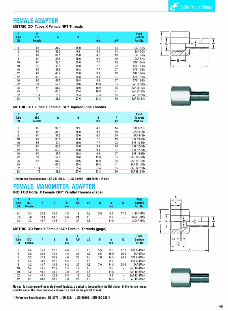
TUBING SELECTION
TUBING HARDNESS
TUBING WALL THICKNESS
Proper selection , handling, installation of tubing when combined with the proportion of the Fluid Controls
Double Ferrule Tube fittings are essential to reliable tubing systems. Although, Fluid Controls Pvt. Ltd. is not a
tubing manufacturer or supplier, we feel it is our duty to impress on our customers the vital importance of
careful selection of high quality tubing in order to install safe and leak free systems. Fluid Controls will be happy
to assist in the selection of such tubes to our customers when requested.
Selection of tubes are based on the material, hardness, wall thickness and surface finish. The ASTM
specifications for various tubes cover material, hardness and wall thickness. They do not give details on
the surface finish.
For example, ASTM A 269, one of the most widely used specifications reads as follows in clause 14.1
under the title “FINISH”.
“ Finished tubes shall be reasonably straight and have smooth ends free from burrs. They shall be free from
injurious defects and shall have a workman like finish. Minor defects may be removed by grinding provided
the wall thickness is not decreased to less than that permitted in clause 13”.
The ASTM is silent on the surface finish which is required to be smooth and free from any scratches, axial
or circumferential which will allow leakage paths along the joints.
We give our comments below on the selections of tubes. These requirements are specified under section
3.1.9 of ASTM A 269 or section 3.1.11 of ASTM A 213
Tubing must always be softer than the fitting material by using the suggested hardness of the tubes as
explained in tubing specification you will ensure joints which work perfectly.
The most misunderstanding about tubing hardness are in the area of stainless steel tubing. Fluid Controls
Double Ferrule Tube Fittings made from stainless steel have been tested successfully with tubing hardness
upto RB 90, the maximum hardness allowable under ASTM A 213 and A 269. Although such tubing
hardness is permissible and Fluid Controls Double Ferrule Fittings will perform satisfactorily on such
tubing, they will not give the maximum advantage and performance for tubes of hardness above RB 80.
Hence, it is suggested that when purchasing stainless steel tubes to ASTM A 213 / A 269, you specify that
the hardness of the tubes should not exceed RB 80. Better still we have found that the best results are
obtained where the stainless steel tubing hardness is in the range RB 70-74. Such tubing ( RB 70-74)
lowers installed costs because it is more easily bent and installed.
Tubing installers should be particularly careful that the full suggested one and quarter turns after snug tight
be performed to ensure the proper joints. This will give the best performance This is especially so in the
case of harder tubing where higher torques are required.
We again repeat that the RB 80 maximum hardness is a suggestion and not a restriction against the use of
Fluid Controls Double Ferrule Fitting in stainless steel to increase the performance of the fitting. However, if
the tubing hardness exceeds RB 90, special fittings needs to be ordered.
The allowable pressure rating of tubings for the wide range of wall thickness are calculated from “S”values
as specified by ANSI Code B 31.1. The range of tubing wall thicknesses vary from 0.028 “ to 0.109 “ in the
inch OD series and 0.75 mm to 2.5 mm in the Metric OD series respectively. These wall thicknesses are
generally preferred for tube sizes upto 1” OD and 25mm OD in the two systems respectively. For higher
tube sizes, these wall thicknesses may be increased to 0.125 or ( 3mm) and 0.167 “ or( 4mm )in the inch
(metric) system respectively.
Tubings with higher wall thickness are generally not recommended as they may lead to lowering of
performance and higher torque requirements to create the joint. Tubings with lower wall thicknesses are
also not recommended as there is a possibility of collapse of the tube.
Fluid Controls will be very happy to provide their customers with working pressure ratings as per ANSI
Code B31.1 for various wall thicknesses in the above mentioned ranges for inch and metric size tubings.
4
Double Ferrule Fittings
49
FEMALE ADAPTERMETRIC OD Tubes X Female NPT Threads
T P FluidTube NPT A B E F ControlsOD Female min. A/F Part No.
3 1/4 31.7 15.0 2.4 14 SAF 3-4N
6 1/8 32.5 9.9 4.6 14 SAF 6-2N
6 1/4 37.1 15.0 4.6 19 SAF 6-4N
8 1/4 37.6 15.0 6.4 19 SAF 8-4N
10 1/4 38.1 15.0 7.7 19 SAF 10-4N
10 3/8 40.1 15.0 7.7 22 SAF 10-6N
10 1/2 46.5 19.8 7.7 27 SAF 10-8N
12 1/4 43.7 15.0 9.1 19 SAF 12-4N
12 1/2 52.3 19.8 9.1 27 SAF 12-8N
16 1/2 47.7 19.8 9.1 27 SAF 16-8N
22 3/4 52.0 20.6 15.0 35 SAF 22-12N
25 3/4 51.2 20.6 15.0 35 SAF 25-12N
25 1 66.5 25.4 19.8 41 SAF 25-16N
32 1.1/4 78.0 25.4 27.4 55 SAF 32-20N
38 1.1/2 88.9 27.6 33.3 60 SAF 38-24N
METRIC OD Tubes X Female ISO* Tapered Pipe Threads
T P FluidTube ISO A B E F ControlsOD Female min. A/F Part No.
6 1/8 32.5 9.9 4.6 14 SAF 6-2Rx
6 1/4 37.1 15.0 4.6 19 SAF 6-4Rx
8 1/4 37.6 15.0 6.4 19 SAF 8-4Rx
10 1/4 38.1 15.0 7.7 19 SAF 10-4Rx
10 3/8 40.1 15.0 7.7 22 SAF 10-6Rx
12 1/4 43.7 15.0 9.1 19 SAF 12-4Rx
12 1/2 52.3 19.8 9.1 27 SAF 12-8Rx
16 1/2 47.7 19.8 9.1 27 SAF 16-8Rx
22 3/4 52.0 20.6 15.0 35 SAF 22-12Rx
25 3/4 51.2 20.6 15.0 35 SAF 25-12Rx
25 1 66.5 25.4 19.8 41 SAF 25-16Rx
32 1.1/4 78.0 25.4 27.4 55 SAF 32-20Rx38 1.1/2 88.9 27.6 33.3 60 SAF 38-24Rx
* Reference Specifications : BS 21: ISO 7/1 : JIS B 0203 : DIN 2999 : IS 554
FEMALE MANOMETER ADAPTERINCH OD Ports X Female ISO* Parallel Threads (gage)
T P F FluidTube ISO A B E A/F a2 d4 b t2 ControlsOd Female min. min. Part No.
1/4 1/4 35.3 13.0 4.8 19 1.6 5.8 9.4 17.0 4 SAF-MAN
3/8 3/8 39.4 14.2 6.6 24 1.6 - 9.9 - 6 SAF-MAN
1/2 1/2 45.7 18.8 7.1 27 1.6 - 14.5 - 8 SAF-MAN
METRIC OD Ports X Female ISO* Parallel Threads (gage)
T P F FluidTube ISO A B E A/F a2 d4 b t2 ControlsOd Female min. min. Part No.
6 1/4 35.3 12.9 4.6 19 1.6 5.5 9.5 17.0 SAF 6-4MAN
6 3/8 38.4 14.1 4.6 24 1.6 6.5 10.0 20.3 SAF 6MAN
6 1/2 42.9 18.9 4.6 27 1.6 7.0 14.5 24.9 SAF 6-8MAN
8 1/4 33.0 12.9 5.5 19 1.6 - 9.5 - SAF 8-4MAN
8 1/2 43.7 18.9 6.2 27 1.6 7.0 14.5 24.9 SAF 8MAN
10 1/4 34.5 12.9 5.5 19 1.6 - 9.5 - SAF 10-4MAN
10 1/2 40.1 18.9 7.0 27 1.6 - 14.5 - SAF 10-8MAN
12 1/4 40.1 12.9 5.5 19 1.6 - 9.5 - SAF 12-4MAN
12 1/2 48.8 18.9 7.0 27 1.6 - 14.5 - SAF 12-8MAN
No seal is made around the male thread. Instead, a gasket is dropped into the flat bottom in the female thread, and the end of the male threaded end exerts a load on the gasket to seal.
* Reference Specifications : BS 2779 : ISO 228/1 : JIS B0202 : DIN-ISO 228/1
Double Ferrule Fittings

3
Female Manometer AdapterFractional & Metric Tube toISO parallel thread (gauge)page- 49
Female AdapterFractional & Metric Tube toNPT thread & ISO tapered pipe threadpage- 48 & 49
Socket Weld Tube ElbowFractional & Metric Tube to tubepage- 42
Female ElbowFractional & Metric Tube to NPT threadpage- 38 & 39
Male Branch TeeFractional & Metric Tube to NPT thread page- 31
Reducing UnionFractional & Metric Tubepage- 13
Reducing Union Tee Fractional & Metric Tubepage- 17
Notes
Double Ferrule Fittings
50
Bulk Head Male ConnectorFractional & Metric Tube to NPT thread page- 25

PRODUCT LOCATOR
2
ReducerFractional & Metric Tubepage- 43
Male AdapterFractional & Metric Tube toNPT thread & ISO tapered pipe threadpage- 45 & 46
Bulkhead ReducerFractional & Metric Tubepage- 44
Male AdapterFractional & Metric Tube toISO parallel threadpage- 47
O Seal Male AdapterFractional Tube toMale Straight Threadpage- 47
Socket Weld Tube ConnectorFractional & Metric Tube to Tubepage- 42
Butt Weld Pipe ConnectorFractional & Metric Tube to pipepage- 41
Female Branch TeeFractional & Metric Tube to NPT threadpage- 40
Butt Weld Pipe ElbowFractional Tube to pipepage- 41
Female Run TeeFractional & Metric Tube to NPT threadpage- 40
Female Manometer ConnectorFractional & Metric Tube toISO parallel thread (gauge)page- 36
Bulkhead Female ConnectorFractional & Metric Tube to NPT thread page- 37
Female ConnectorFractional & Metric Tube toNPT thread & ISO tapered pipe threadpage- 34 & 35
Positionable Male Run TeeFractional & Metric Tube to ISO parallel thread SAE / MS straight threadpage- 32 & 33
Positionable Male Run TeeFractional & Metric Tube to ISO parallel thread SAE / MS straight threadpage- 32 & 33
Male ElbowFractional & Metric Tube toNPT thread & ISO tapered pipe threadpage- 26 & 27
45 Dgree Male ElbowFractional & Metric Tube toNPT parallel threadpage- 28
45 Deg. Positionable Male ElbowFractional & Metric Tube toNPT parallel threadpage- 28
45 Deg. Positionable Male ElbowFractional & Metric Tube toNPT parallel threadpage- 28
Positionable Male ElbowFractional & Metric Tube toISO parallel threadSAE / MS straight threadpage- 29
Positionable Male ElbowFractional & Metric Tube toISO parallel threadSAE / MS straight threadpage- 29
Male Run TeeFractional & Metric Tube to NPT thread page- 30
Coupling CapFractional & Metric Tubepage- 10
Tube End ClosureFractional & Metric Tubepage- 11
Fitting End ClosureFractional & Metric Tubepage- 11
UnionFractional & Metric Tubepage- 12
Front & Back FerruleFractional & Metric Tubepage- 10
Bulkhead UnionFractional & Metric Tubepage- 14
Bulkhead Reducing UnionFractional & Metric Tubepage- 14
Union ElbowFractional & Metric Tubepage- 15
Bulkhead ElbowFractional & Metric Tubepage- 15
Union Tee Fractional & Metric Tubepage- 16
Male ConnectorFractional & Metric Tube toNPT thread & ISO tapered pipe threadpage- 19, 20 & 21
CrossFractional & Metric Tubespage- 18
Male ConnectorFractional & Metric Tube toISO parallel thread - Rppage- 22
Male ConnectorFractional & Metric Tube toISO parallel thread - Rspage- 23
Notes
Double Ferrule Fittings
51
O Seal Male ConnectorFractional & Metric Tube toISO parallel thread & straight thread-UNFpage- 24
Positionable Male Branch TeeFractional & Metric Tube to ISO parallel thread SAE /MS straight threadpage-32 & 33
Positionable Male Branch TeeFractional & Metric Tube to ISO parallel thread SAE /MS straight threadpage-32 & 33
Positionable Male Run TeeFractional & Metric Tube to ISO parallel thread SAE / MS straight threadpage- 32 & 33
Positionable Male ElbowFractional & Metric Tube toISO parallel threadSAE / MS straight threadpage- 29
45 Deg. Positionable Male ElbowFractional & Metric Tube toNPT parallel threadpage- 28
Positionable Male Branch TeeFractional & Metric Tube to ISO parallel thread SAE /MS straight threadpage-32 & 33

1
INTRODUCTION
Fluid Controls Double Ferrule Compression Tube Fittings Have The Following Features
DESIGN
PERFORMANCE
ASSEMBLY
SERVICE
Fluid Controls Double Ferrule Compression Tube Fittings provide leak proof torque free seals at all tubing connections. They eliminate hazardous leaks in instrumentation, process, pneumatic, hydraulic, gas and other applicable tubing system which could otherwise turn out to be costly to the installation.
The basic Fluid Controls Double Ferrule Tube Fittings is a four piece Fitting consisting of the Nut, the
Back Ferrule, the Front Ferrule and the Body. When installed, it becomes a five piece connection with the
addition of the tubing providing a solid leak free joint.
The two ferrules grasp tightly around the tube with no damage to the tube wall. Exhaustive tests have
proven that the tubing will yield before a Fluid Control Double Ferrule joint starts leaking.
The secret behind the success of the Fluid Controls Double Ferrule Fitting lies in the two ferrule
design which is a combination of geometry and metallurgy. All the action in the fitting is by an axial
movement along the tube instead of a rotary motion to create the joint. This axial movement prevents any
torque to be transmitted from a fitting to the tubing. Since there is no initial strain in the tubing, the making of
the joint does not weaken the tubing.
Another advantage of the Fluid Controls Double Ferrule Fitting is that the sequential action of the twin
ferrule overcomes variations in the wall thickness, hardness and dimensional tolerance of the tubes. This
way proper ferrule interaction compensates for most of the variables which lead to failure in other fittings.
Fluid Controls Double Ferrule Fittings are easy to install and require no special tools in the process.
They are reusable several times and can withstand heavy impulse and vibration both in vacuum and
pressure systems. Absence of damage to the tube surface prevents fatigue failure.
We give below a summary of the advantages of Fluid Controls Double Ferrule Fitting.
nBe self aligning
nWorks on thick and thin wall tubing
nResists vibration
nWorks on a variety of tube materials
nHave all components made of the same material and hence possess thermal compatibility and
corrosion resistance.
nResistance to temperature cycling
nCompensates for the variables encountered in tube, materials,
nDimensions and metallurgy.
nDoes not significantly reduce flow area
nWorks on vacuum as well as low and high pressures
nSeals at low cryogenic temperatures as well as elevated temperatures rated for the tube
nSeals consistently over a wide range of temperature cycling
nSeals repeatedly under make and break conditions
nResistant to pressure upto the burst point with the tubing without leakage.
nUses geometry rather than torque for uniformity of make-up. It requires only one and quarter turns
after snug tight to complete the joint.
nDoes not require dis-assembly and inspection of ferrule swaging at every make-up.
nDoes not require any special tools for assembly.
Fluid Controls Double Ferrule Tube Fittings are available in a wide range of materials, sizes, connections and
configurations from our local distributors with substantial back up stocks to support our dealers
inventories.
Notes
Double Ferrule Fittings
52

J. V. PATEL, I. T. I. COMPOUND, B. MADHURKAR MARG,
OPP. ELPHINSTONE ROAD STATION, (W.R.)
MUMBAI 400 013 INDIA
Tel. : +91-22-2430 4411 / 2430 3075 / 2432 9380
Fax : +91-22-2436 2160
email : [email protected]
Website : www.fluidcontrols.com
FLUID CONTROLS PRIVATE LIMITEDAccreditedby the RvA
ISO-9001 REGISTERED FIRMDet Norske veritas B.V., THE NETHERLANDS
FLUID CONTROLS PRIVATE LIMITED
DOUBLE FERRULE FITTINGS
desi
gn@
capr
ia.n
et