dnapl site characterization using a partitioning interwell tracer test
TRANSCRIPT

Final
DNAPL Site Chracterization Using aPartioning Interwell Tracer Test at
Site 88, Marine Corps BaseCamp Lejeune, North Carolina
Prepared for:
Department of the Navy:
Naval Facilities Engineering Service CenterRestoration Development CenterPort Hueneme, California
and
Naval Facilities Engineering CommandAtlantic DivisionNorfolk, Virginia
Prepared by:
Duke Engineering & ServicesAustin, Texas
In Cooperation with:
Baker Environmental, Inc.Coraopolis, Pennsylvania
July 1999
Approved for public release; distribution is unlimited.

Camp Lejeune PITT Report
i
TABLE OF CONTENTS
ACRONYMS AND ABBREVIATIONS ............................................................................vii
EXECUTIVE SUMMARY................................................................................................ ix
1.0 INTRODUCTION......................................................................................................11.1 Goals and Objectives.......................................................................................51.2 DNAPL Occurrence and Definitions.................................................................5
2.0 SITE BACKGROUND...............................................................................................82.1 Site History.......................................................................................................82.2 Site Stratigraphy ..............................................................................................82.3 Hydrogeologic Setting......................................................................................92.4 Surface Water..................................................................................................92.5 Water Supply Wells .......................................................................................10
3.0 DNAPL SOURCE-ZONE INVESTIGATIONS.........................................................113.1 Phase 1: Initial DNAPL Source-Zone Investigations.....................................11
3.1.1 Soil Sampling Method for VOC Analysis ............................................113.1.2 Results of Initial DNAPL Source-Zone Investigations ........................133.1.3 Expanded DNAPL Source-Zone Investigation and Aquifer Testing ...14
3.1.3.1 Additional DNAPL Source-Zone Investigation ........................143.1.3.2 Aquifer Testing of the DNAPL-Contaminated Zone................15
3.2 Phase 2: DNAPL Source-Zone Characterization ...........................................173.2.1 Cone Penetrometer Tests ..................................................................173.2.2 Soil Borings to Delineate Extent of DNAPL Zone...............................183.2.3 Soil Sampling during Installation of Test Zone Wells .........................19
3.3 Soil and Water Analysis.................................................................................203.3.1 Soil Analysis .......................................................................................203.3.2 NAPLANAL Estimates of DNAPL Saturations....................................223.3.3 Ground-Water and Source-Water Characterization ...........................26
4.0 TEST ZONE WELL-FIELD INSTALLATION ..........................................................314.1 Test Zone Wells and DNAPL Recovery Wells...............................................314.2 Drilling Methods for Well-Field Installation.....................................................324.3 Well Configuration and Construction .............................................................32
4.3.1 Test Zone Wells and Recovery Wells ................................................334.3.2 Multilevel Sampler Installations ..........................................................374.3.3 Castle Hayne and Aquitard Monitor Points.........................................37
4.4 Well Development..........................................................................................39
5.0 SITE GEOSYSTEM................................................................................................40

Camp Lejeune PITT Report
ii
5.1 DNAPL Distribution ........................................................................................45
6.0 FREE-PHASE DNAPL RECOVERY AT SITE 88 ...................................................46
7.0 LABORATORY STUDIES AND TRACER SELECTION.........................................487.1 Laboratory Scale Studies...............................................................................48
7.1.1 Preliminary Laboratory Studies ..........................................................487.2 Partitioning Tracer Selection..........................................................................48
7.2.1 Measurement of Static Partition Coefficients .....................................497.2.3 Soil Column Experiments ...................................................................51
7.3 Results from Soil Column Experiments .........................................................517.3.1 Partitioning Tracers in Uncontaminated Soil ......................................517.3.2 Partitioning Tracers in Contaminated Soil ..........................................53
7.4 Tracers Selected for Further PITT Design .....................................................567.5 Summary and Conclusions ............................................................................56
8.0 PITT DESIGN SIMULATIONS................................................................................588.1 PITT Design Strategy and Modeling Approach..............................................588.2 Simulation Model Development .....................................................................60
8.2.1 Well-Field Configuration.....................................................................608.2.2 Simulation Domain .............................................................................608.2.3 Physical Properties of Porous Media and Fluids ...............................62
8.3 CITT Design...................................................................................................638.4 PITT Design...................................................................................................66
9.0 CONSERVATIVE INTERWELL TRACER TEST (CITT) ........................................73
10.0 PITT FIELD IMPLEMENTATION..........................................................................8110.1 PITT Operations ..........................................................................................8110.2 PITT Tracer Sampling..................................................................................8210.3 PITT Tracer Analysis ...................................................................................8310.4 Water Quality Monitoring .............................................................................83
11.0 PITT RESULTS AND DATA ANALYSIS ..............................................................8511.1 Laboratory Analytical Results ......................................................................85
11.1.1 PITT Samples ..................................................................................8511.1.2 Monitor Well Samples ......................................................................86
11.2 Tracer Data Analysis Approach ...................................................................8611.3 Method of First Temporal Moment Analysis ................................................9011.4 PITT Data Analysis ......................................................................................93
11.4.1 Extraction Well Tracer Data Analysis ...............................................9311.4.2 Multilevel Sampler Tracer Data Analysis........................................10211.4.3 Comparison of PITT results to Simulation Predictions ...................105
11.5 Error Analysis...........................................................................................105

Camp Lejeune PITT Report
iii
11.6 Summary and Conclusions of PITT Results ..............................................112
12.0 SUMMARY AND CONCLUSIONS .....................................................................114
13.0 REFERENCES...................................................................................................116
LIST OF APPENDICES
Appendix A Procedure for Soil Sampling with Methanol PreservationAppendix B Geologic Logs and Well Construction DetailsAppendix C Aquifer Test Data, Drawdown and Curve Match PlotsAppendix D CPT LogsAppendix E Non-VOC Soil Analyses (Soil Moisture, XRD), Major Ion Analyses, and
Ground-Water VOC AnalysesAppendix F Soil Concentration Correction CalculationsAppendix G Porosity Calculation and NAPLANAL Paper (Mariner et al, 1997)Appendix H Laboratory Results of Soil Core VOC AnalysesAppendix I Capillary Pressure Tests: Results, Data Analysis and InterpretationAppendix J Plots of DNAPL/Water Interface ElevationsAppendix K Laboratory Procedures for Tracer Selection and Column Tests, and
the Method of Moments for Data AnalysisAppendix L DE&S Standard Operating ProceduresAppendix M PITT Flow Rates, Cumulative Volumes, and Water LevelsAppendix N PITT Operations – Field Measured Water Quality DataAppendix O PITT Analytical Data, Analytical Method SOP, QA/QC ReportAppendix P Sample Holding Time StudyAppendix Q EACN Discussion

Camp Lejeune PITT Report
iv
LIST OF TABLESTable 3.1 Well Construction Details ...........................................................................15Table 3.2 Fraction of Organic Carbon (foc) in Selected Soil Samples.........................21Table 3.3 Soil Water Content .....................................................................................22Table 3.4 Soil VOC Concentrations of Subsurface Soils at Building 25.....................22Table 3.5 Ground-Water VOC Concentrations...........................................................26Table 3.6 Major Ion Concentrations in Ground-Water and Source-Water
Samples ................................................................................................30Table 6.1 DNAPL Levels in Wells at Site 88 ..............................................................46Table 7.1 Partition Coefficients of Alcohols with Camp Lejeune Site 88
DNAPL ..................................................................................................50Table 7.2 Retardation of Partitioning Tracers in Uncontaminated Camp
Lejeune Soil ..........................................................................................53Table 7.3 DNAPL Saturation Estimated by Partitioning Tracers, Column
CLJ#2....................................................................................................54Table 7.4 DNAPL Saturation Estimated by Partitioning Tracers, Column
CLJ#3....................................................................................................54Table 7.5 Residence Times for Tracers during Partitioning Tracer
Experiments ..........................................................................................56Table 8.1 Tracers and their Partition Coefficients ......................................................62Table 8.2 Design Summary of CITT Flow Rates ........................................................63Table 8.3 Design Summary of CITT Phases ..............................................................65Table 8.4 Summary of Tracer Injection Operation......................................................65Table 8.5 Sampling Schedule for the CITT ................................................................65Table 8.6 Summary of CITT Simulation Predictions...................................................66Table 8.7 Design Summary of PITT Flow Rate ..........................................................67Table 8.8 Design Summary of PITT Operation Phases .............................................71Table 8.9 Summary of Tracer Injection Operation......................................................71Table 8.10 Sampling Schedule for the PITT ................................................................71Table 8.11 Summary of PITT Simulation Predictions...................................................72Table 9.1 Summary of CITT Results ..........................................................................80Table 10.1 Tracer Volumes and Approximate Concentrations per Tank......................81Table 11.1 Summary of Extraction Well PITT results.................................................102Table 11.2 Summary of Multilevel Sampler (MLS) Tracer Data Analysis
Results ................................................................................................104Table 11.3 Estimated Effective Permeability Contrast ...............................................104Table 11.4 Uncertainty of DNAPL Saturation Estimates (1-propanol vs. 1-
heptanol) .............................................................................................110

Camp Lejeune PITT Report
v
LIST OF FIGURES
Figure 1.1 Location Map.............................................................................................2Figure 1.2 Dissolved PCE Plume Boundary in the Shallow Aquifer –
August 1996 ............................................................................................3Figure 1.3 Dissolved PCE Plume Boundary in the Upper Portion of the
Castle-Hayne Aquifer – August 1996 ......................................................4Figure 1.4 Generalized Diagram of DNAPL Migration in Water-Wet Porous
Media ......................................................................................................7Figure 3.1 DNAPL Source-Zone Investigation: Locations of Soil Borings,
CPT Pushes, and Wells ........................................................................12Figure 3.2 Pumping Test Location Map....................................................................16Figure 3.3 DNAPL Zone Boundary and Cross Section Transect Locations .............27Figure 3.4 Cross Section A-A’ with Soil PCE Concentrations and
Estimated DNAPL Saturations ..............................................................28Figure 3.5 Cross Section A-A’ with Soil PCE Concentrations and
Estimated DNAPL Saturations ..............................................................29Figure 4.1 Location and Configuration of the Demonstration Well Array .................34Figure 4.2 Injection Well Construction Detail............................................................35Figure 4.3 Extraction Well Construction Detail .........................................................36Figure 4.4 Generalized Geosystem Cross Section of DNAPL Zone at Site
88 ..........................................................................................................38Figure 5.1 Water Level Elevation in the Shallow Aquifer..........................................42Figure 5.2 Upper Surface of Clay Aquitard Beneath Building 25..............................43Figure 5.3 Total Thickness of Clay Aquitard Beneath Building 25............................44Figure 7.1 Partitioning Tracer Response in Uncontaminated Soil, Column
Experiments CLJ#1 and CLJ#2.............................................................52Figure 7.2 Partitioning Tracer Response in DNAPL Contaminated Soil,
Column Experiments CLJ#2 and CLJ#3 ...............................................55Figure 8.1 Plan View of the Simulation Grid and Aquitard Elevation
Contour .................................................................................................61Figure 8.2 Prediction of CITT Tracer Response.......................................................64Figure 8.3 Prediction of Extraction Wells EX01 and EX02 Tracer
Response ..............................................................................................68Figure 8.4 Prediction of Extraction Wells EX03 and EX04 Tracer
Response ..............................................................................................69Figure 8.5 Prediction of Extraction Wells EX05 and EX06 Tracer
Response ..............................................................................................70Figure 9.1 PITT Site Map .........................................................................................74Figure 9.2 CITT Bromide Break-Through Curves.....................................................76Figure 9.3a CITT Tracer Response at Extraction Wells EX01 and EX02 ..................77Figure 9.3b CITT Tracer Response at Extraction Wells EX03 and EX04R................78Figure 9.3c CITT Tracer Response at Extraction Wells EX05 and EX06...................79

Camp Lejeune PITT Report
vi
Figure 11.1 Example of QA/QC of Tracer Data..........................................................88Figure 11.2 Comparison of Degree of Separation of Tracer Response at
EX01 .....................................................................................................89Figure 11.3 Example of Tracer Curve Fitting..............................................................91Figure 11.4a Extraction Well EX01: Hexanol Tracer Response..................................94Figure 11.4b Extraction Well EX01: Heptanol Tracer Response.................................95Figure 11.5 Extraction Well EX02: Heptanol Tracer Response.................................96Figure 11.6 Extraction Well EX03: Heptanol Tracer Response.................................97Figure 11.7a Extraction Well EX04R: Hexanol Tracer Response ...............................98Figure 11.7b Extraction Well EX04R: Heptanol Tracer Response ..............................99Figure 11.8 Extraction Well EX05: Heptanol Tracer Response...............................100Figure 11.9 Extraction Well EX06: Heptanol Tracer Response...............................101Figure 11.10 Multi-Level Sample Point Tracer Responses ........................................103Figure 11.11 Comparison of Non-partitioning Tracer Curves: UTCHEM
Prediction vs. Actual PITT Data at Extraction Wells EX01 andEX02 ...................................................................................................106
Figure 11.12 Comparison of Non-partitioning Tracer Curves: UTCHEMPrediction vs. Actual PITT Data at Extraction Wells EX03 andEX04R.................................................................................................107
Figure 11.13 Comparison of Non-partitioning Tracer Curves: UTCHEMPrediction vs. Actual PITT Data at Extraction Wells EX05 andEX06 ...................................................................................................108
Figure 11.14 Water Level Elevations During the PITT ...............................................109

Camp Lejeune PITT Report
vii
ACRONYMS AND ABBREVIATIONS
4M2P 4-methyl-2-pentanolAST above-ground storage tankamsl above mean sea levelBaker Baker Environmentalbgs below ground surfaceBr- bromideBTOC below top-of-casingC concentration of tracerCaCl2 calcium chlorideCITT conservative interwell tracer testCLEAN Comprehensive Long-Term Environmental Action NavyCPT cone penetrometer testcm/sec centimeters per secondDAS data acquisition systemDCE cis-1,2-dichloroetheneDE&S Duke Engineering & ServicesDNAPL dense nonaqueous phase liquidDOD Department of DefenseDSI Drilling Service Inc.dyne/cm dynes per centimeterEPA Environmental Protection AgencyESTCP Environmental Securities Technology Certification ProgramFID flame ionization detectorft feetft bgs feet below ground surfaceft/day feet per dayfoc fraction of sedimentary organic carbon in aquifer material (wt/wt)gal gallonGC gas chromatographyg/cm3 grams per cubic centimetergpm gallons per minuteIFT interfacial tensionin inchIRP Installation Restoration Programkg/m3 kilogram per cubic meterkavg average permeabilityK hydraulic conductivityΚ i partition coefficient for the ith tracer

Camp Lejeune PITT Report
viii
Acronyms and Abbreviations, Continued
Κn partition coefficient for a non-partitioning tracerΚp partition coefficient for a partitioning tracerLANTDIV Atlantic Division, Naval Facilities Engineering Commandlb poundLNAPL light nonaqueous phase liquidm meterm/s2 meters per seconds squaredµm micrometerMCB Marine Corps BaseMLS multilevel samplerµg/L micrograms per literµg/Kg micrograms per kilogrammg/Kg milligrams per kilogrammg/L milligrams per litermL milliliterNAPL nonaqueous phase liquidNAVFAC Naval Facilities Engineering CommandNFESC Naval Facilities Engineering Service CenterNRMRL National Risk Management Research LaboratoryOHM OHM Remediation Services CorporationPA performance assessmentPCE tetrachloroethene (i.e., perchloroethylene)PID photo-ionization detectorPITT partitioning interwell tracer testppb parts per billionppm parts per millionQ flow rateQA/QC quality assurance/quality controlRAC Remedial Action ContractorRI Remedial InvestigationSEAR surfactant-enhanced aquifer remediationSOP Standard Operating ProcedureTCE trichloroetheneUST underground storage tankVOC volatile organic compoundXRD X-ray diffraction

Camp Lejeune PITT Report
ix
EXECUTIVE SUMMARY
A partitioning interwell tracer test (PITT) was recently completed at Site 88, the locationof the Morale, Welfare, and Recreation (MWR) Dry Cleaners at the Marine Corps Base(MCB) Camp Lejeune, North Carolina. This PITT was conducted to estimate thesaturation, volume, and spatial distribution of tetrachloroethene (PCE) that is present asa dense non-aqueous phase liquid (DNAPL) within the selected test area. The PITTresults provide characterization of the initial DNAPL conditions at the site, in preparationfor a surfactant-enhanced aquifer remediation (SEAR) demonstration to removeDNAPL from the surficial (shallow) aquifer at the site. The PITT is the most recent ofmany field investigations that have been conducted in the past year to characterize theDNAPL contamination at Site 88. The PITT data has confirmed the results of earliersoil and ground-water investigations, which indicated that the highest DNAPLsaturations are located in the shallow aquifer regions adjacent to the dry-cleaningbuilding, and within a layer of low-permeability sediments (i.e., clayey silt) just above aclay aquitard. A summary of the DNAPL investigations and other field activitiesconducted in conjunction with the PITT are provided in this report, along with the PITTresults and data analysis.
The DNAPL source-zone investigations at MCB Camp Lejeune have been co-funded bythe Environmental Securities and Technology Certification Program (ESTCP) and theAtlantic Division, Naval Facilities Engineering Command (LANTDIV), and wereconducted in a teaming arrangement between Duke Engineering & Services and BakerEnvironmental (the LANTDIV CLEAN program contractor at Camp Lejeune). Additionalsite support was provided by OHM Remediation Services Corporation (the LANTDIVRAC program contractor at Camp Lejeune). These investigations proceeded in threephases, as described below.
• Phase 1: July – August, 1997
The objectives of Phase 1 were to: (1) locate the DNAPL zone and (2) performpreliminary characterization of the DNAPL-contaminated geosystem (i.e.,hydrostratigraphy, hydraulic and geochemical properties of the aquifer, andapproximate DNAPL saturations). The Phase 1 investigation consisted of a small-scale soil-sampling program during which soil borings were pushed continuously tocollect detailed lithologic data and soil samples were collected using in-fieldmethanol preservation. This was followed by well installation to conduct hydraulictesting. Borings were completed beneath the building and around the buildingperimeter to a depth of about 21 feet below ground surface (ft bgs). Following thedevelopment of the newly installed wells, free-phase DNAPL was collected in two ofthe wells. The soil analytical results confirmed the presence of residual PCEDNAPL at a depth interval of approximately 17 to 20 ft bgs. Hydraulic testing

Camp Lejeune PITT Report
x
demonstrated that the aquifer soils had sufficient permeability for implementation ofthe SEAR technology.
• Phase 2: November-December, 1997
The objectives of Phase 2 were to: (1) roughly delineate the horizontal and verticalextent of DNAPL at the site, (2) establish baseline DNAPL saturations in theselected test area using soil borings and (3) perform additional site characterizationto refine the geosystem model for the test well-field design. Phase 2 work combinedlaboratory and modeling studies to achieve the latter objective. The laboratorystudies, using DNAPL and sediments collected from the site, resulted in theselection of a suite of tracers suitable for a PITT under site-specific conditions.Using site data gained from Phase 1 and 2 field investigations as input parameters,a geosystem model of the site was constructed using UTCHEM, a three-dimensional multi-phase flow simulator. Initial simulations with UTCHEM providedthe optimum well geometry and spacing for the PITT and the subsequent surfactantflood. The designed well field, sited adjacent to Building 25, consists of a total ofthree injection and six extraction wells arranged in a 3X3X3 line-drive configuration,with a hydraulic control well located at each end of the row of injection wells. Thus,the test well field comprises 11 wells in total. The test area formed by the 3x3x3array of injection and extraction wells is 20 ft wide by 30 ft long. Phase 2 activitiesculminated with the installation of the demonstration wells.
• Phase 3: January-July, 1998
The objectives of Phase 3 were to measure the DNAPL volume and averagesaturations within the test zone with a PITT, in preparation for the SEARdemonstration. Phase 3 of the DNAPL source-zone investigation included fieldimplementation of the PITT as well as preparatory field activities. First, free-phaseDNAPL recovery was undertaken by means of pumping selected wells that showedDNAPL accumulation. This was followed by a water flood in the test-zone well field.An estimated 30-60 gallons of DNAPL was removed from the subsurface during thefree-phase DNAPL recovery effort. Secondly, a conservative interwell tracer test(CITT) was conducted to evaluate the preliminary PITT design (i.e., flow rates, testduration) as determined by the Phase 2 design modeling. Using bromide as thetracer, tracer breakthrough was measured at the six extractor wells to determine theactual tracer residence time in the interwell swept pore volume between a given pairof injection and extraction wells. The results of the CITT showed that only minorrevisions were needed in the initial design (i.e., injection and extraction flow rates) tofinalize the PITT design.
The PITT began on May 13, 1998, continued for 40 days, and terminated on June22, 1998. Data analysis estimated that 74-88 gallons of DNAPL are present in the4,800-gallon swept pore volume of the test zone. Average DNAPL saturations in the

Camp Lejeune PITT Report
xi
test zone are highest in the area adjacent to the north wall of Building 25, atapproximately 4% saturation, and decrease in a northerly direction away from thebuilding to about 0.4% saturation at a distance of approximately 20 ft north of thebuilding. However, the results of soil column studies conducted prior to the PITTsuggest that the low-level DNAPL saturation (i.e. 0.4%) measured in the arealocated approximately 20 ft north of the building is actually the result of tracersorption to sedimentary organic matter that is observable as peat particles in thesediments. Therefore the area of the test zone 20 ft north of the building is believedto be DNAPL free.
Phase 4, the SEAR demonstration began in April 1999 and is at the time of writingin progress (July 1999). The SEAR demonstration will be followed immediately by asecond PITT to measure the volume of DNAPL remaining in the test zone. Theresults of the pre-SEAR and post-SEAR PITTs will be compared to assess theperformance of the surfactant flood in removing DNAPL from the test zone at Site88. This performance assessment of the SEAR demonstration will also determinethe volume of DNAPL remaining in the test zone after the SEAR demonstration.Post-SEAR soil samples will also be collected from the test zone and analyzed forvolatile organic compounds to provide additional evidence of the performance of thesurfactant flood. The SEAR demonstration and post-SEAR PITT are scheduled forcompletion in late August 1999.

Camp Lejeune PITT Report
1
1.0 INTRODUCTION
A remedial investigation (RI) conducted by Baker Environmental (Baker) during 1996 to1997 revealed the presence of dissolved phase tetrachloroethene (PCE) in the groundwater at Operable Unit No. 15 (Site 88) at Marine Corps Base (MCB) Camp Lejeune,North Carolina (Baker; 1996,1998a). The location of Site 88 is shown in Figure 1.1,and is roughly defined as the area delineated by the extent of the aqueous phase PCEplume. The source of the PCE plume is the Base dry cleaning facility, which is housedin Morale, Welfare, and Recreation (MWR), Building 25. The PCE plume extendsgenerally to the northwest and south from Building 25, as seen in Figure 1.2. AqueousPCE concentrations were reported in the RI (Baker, 1998a) to range as high as54.9 mg/L (54,882 µg/L; Figure 1.2) in the shallow aquifer, and also in the UpperPortion of the Castle Hayne Aquifer at concentrations up to 26.6 mg/L (26,592 µg/L;Figure 1.3). The Upper Portion of the Castle Hayne Aquifer has been used as adrinking water aquifer in the vicinity of MCB Camp Lejeune and nearby Jacksonville,NC. However, drinking water supplies do not currently appear to be threatened by theground-water contaminants related to Site 88.
The RI was conducted by Baker Environmental (under the LANTDIV CLEAN[Comprehensive Long-Term Environmental Action Navy] program) for the AtlanticDivision, Naval Facilities Engineering Command (LANTDIV) under the InstallationRestoration Program (IRP) at MCB Camp Lejeune. Meanwhile, the Naval FacilitiesEngineering Service Center (NFESC), located in Port Hueneme, California, wassearching for a site to conduct a field demonstration of surfactant-enhanced aquiferremediation (SEAR) with surfactant recycling and reinjection. The SEAR fielddemonstration is funded by the Department of Defense (DOD) under its EnvironmentalSecurities Technology Certification Program (ESTCP) in an effort to promote innovativetechnologies for effective remediation methods at DOD sites contaminated with dense,non-aqueous liquid (DNAPL). Chlorinated solvents, such as PCE and trichloroethene(TCE), when present in the subsurface as an immiscible liquid (i.e., DNAPL) slowlydissolve and provide a persistent source of aqueous contamination to the subsurface.Such sites are not cost-effectively remediated by traditional pump-and-treat methods(Mackay and Cherry, 1989).
The Site 88 RI reported aqueous PCE concentrations up to 54 mg/L present in theshallow aquifer, which is approximately 23% of the solubility of PCE based upon anaqueous solubility of 240 mg/L (Broholm and Feenstra, 1995; West, 1992). Suchaqueous concentrations strongly suggest the presence of PCE DNAPL at Site 88.Based upon such evidence for the likelihood of DNAPL beneath Building 25, Site 88was chosen by the ESTCP team, with support from LANTDIV, as a candidate site for

Camp Lejeune PITT Report
2
Figure 1.1. Location Map

Camp Lejeune PITT Report
3
Figure 1.2. Dissolved PCE Plume Boundary in the Shallow Aquifer – August 1996

Camp Lejeune PITT Report
4
Figure 1.3. Dissolved PCE Plume Boundary in the Upper Portion of the Castle-HayneAquifer – August 1996

Camp Lejeune PITT Report
5
the ESTCP project pending the results of a preliminary DNAPL site investigation tolocate the DNAPL zone beneath Building 25. This preliminary DNAPL source-zoneinvestigation, conducted by Duke Engineering & Services (DE&S) in late 1997, in ateaming arrangement with Baker, confirmed the presence of DNAPL at Site 88. Twosubsequent DNAPL investigations were then conducted to delineate the approximateextent of the DNAPL zone at Site 88, and to obtain estimates of aquifer hydraulicproperties. The results of these preliminary DNAPL-zone investigations met the site-selection criteria for SEAR, therefore Site 88 was selected to be the demonstration sitefor the ESTCP project.
The purpose of this report is to summarize the PITT results as well as the results fromall earlier DNAPL source-zone investigations conducted by DE&S at Site 88 inpreparation for the upcoming SEAR demonstration.
1.1 Goals and Objectives
Performance assessment of the SEAR will be accomplished using PITTs. The PITTswill provide a quantitative comparison of the DNAPL volume and distribution in the testzone before and after the SEAR.
The goals of the pre-SEAR DNAPL investigations were to:
• define the geosystem of the test zone for the purpose of PITT and SEAR design,and;
• measure initial DNAPL conditions in the test zone with a PITT in preparation forthe SEAR demonstration.
To meet the above goals, the specific objectives of the pre-SEAR DNAPL investigationswere to design and conduct a PITT to:
• measure the total volume and average saturation of DNAPL in the test zone;and
• determine both the horizontal and vertical spatial distribution of DNAPL in thetest zone.
1.2 DNAPL Occurrence and Definitions
PCE solvent is considered a DNAPL due to its relatively high density (1.63 g/cm3) andimmiscibility in water (interfacial tension in water = 47.48 dyn/cm; Demond and Lindner,1993). If spilled in sufficient quantities, PCE DNAPL migrates downward from the

Camp Lejeune PITT Report
6
DNAPL entry location, through the vadose and saturated zones until stopped by a low-permeability barrier (i.e., capillary barrier), such as a clay. It can then migrate laterallydownslope along the capillary barrier. As DNAPL flows through porous media, it leavesbehind a trail of residual DNAPL that partially fills the pore spaces (see Figure 1.4).Residual DNAPL is held in the pore spaces by capillary forces and, due to its lowsolubility remains as a persistent source of contamination to the ground water. Free-phase DNAPL is defined as DNAPL existing in the subsurface under a positivepressure such that it can flow into a well (EPA, 1992). The Environmental ProtectionAgency (EPA, 1992) defines those areas containing residual or free-phase DNAPL asDNAPL zones.

Camp Lejeune PITT Report
7
Figure 1.4. Generalized Diagram of DNAPL Migration in Wate
r-Wet Porous Media
Camp Lejeune PITT Report
8
2.0 SITE BACKGROUND
This section provides a brief description of site historical operations, and generalhydrology and hydrogeology for the Site 88 area. This information is provided toacquaint the reader with the general setting of Site 88. However, for more detailedinformation with respect to the hydrogeology of the SEAR demonstration area, seeSection 5.0.
2.1 Site History
Building 25 has been operating as a dry cleaning facility since the 1940s. VarsolTM, apetroleum distillate, or “mineral spirit”, was used as the dry cleaning fluid from the1940s through the 1970s. During the 1970s, due to the high flammability of VarsolTM,the facility began to use PCE as the dry cleaning fluid. VarsolTM was stored inunderground storage tanks (USTs) located on the northern side of the building. TheVarsolTM USTs, most probably installed in the 1940s, were removed in November of1995 by OHM Remediation Services (OHM). PCE was stored on site in the samevicinity as the VarsolTM but in 150-gallon above-ground storage tanks (ASTs).
At the time the USTs were removed in 1995, contamination of the soil and ground waterwas suspected. During informal interviews conducted during the DNAPL investigation,dry cleaning personnel indicated that historical operating practices included disposal ofspent PCE into floor drains. The tanks, floor drains, and associated underground pipesmay have provided conduits for contamination to reach the subsurface. The drycleaners still use PCE, but current practices involve storing PCE in a 150-gallon self-contained AST that is located inside Building 25, and the dry cleaning machines arefully self-contained. The first such unit was brought on line in December 1986, and thesecond in March 1995.
2.2 Site Stratigraphy
A relatively uniform depositional sequence of sediments has been observed in boringsacross the site. The surficial aquifer, referred to as the shallow aquifer in this report,consists of fine to very-fine sands and silt which typify the sediments encountered fromthe surface to a depth of approximately 18 feet below ground surface (ft bgs). Theshallow aquifer is bound below by a silty clay layer that varies in thickness across Site88. Previous investigations have reported that the clay layer is laterally discontinuous insome areas of Site 88 (Baker, 1998a). However, the clay layer appears to becontinuous in the vicinity of the DNAPL zone, as discussed in Section 5.0.

Camp Lejeune PITT Report
9
Beneath the clay layer is an interval composed of fine to medium sand with some silt toa depth of over 100 ft bgs, based on boring logs for monitor wells completed in the area(Baker, 1998a). This hydrostratigraphic unit is identified in the RI report as the UpperPortion of the Castle Hayne Aquifer (Baker, 1998a). In areas where the clay layer is notpresent, the shallow aquifer and Castle Hayne Aquifer are in direct hydrauliccommunication.
2.3 Hydrogeologic Setting
In the demonstration area, the water table varies annually from about 7-9 feet bgs, orabout 16-18 feet above mean sea level (amsl), and the shallow aquifer is separatedfrom the Upper Portion of the Castle Hayne Aquifer by the clay layer. As discussedabove, the clay layer acts as an aquitard between the two hydrostratigraphic units.Core samples show that the clay layer is approximately 14-16 ft thick in the SEARdemonstration area. This aquitard core was collected through a surface casing, whichwas installed for the completion of a Castle Hayne Aquifer monitor well located in theDNAPL zone. Cone penetrometer tests conducted outside the DNAPL zone show theaquitard thinning towards the northeast and southwest of Building 25. Furtherdiscussion of the clay layer morphology is presented in Section 5.0 of this report.
Water levels in the Castle Hayne Aquifer are approximately seven feet lower than waterlevels in the shallow aquifer. The difference in water levels between the shallow aquiferand the Upper Portion of the Castle Hayne Aquifer, as well as the fact that DNAPL haspooled on the clay layer, are evidence of the competency of the clay layer as anaquitard in the demonstration area. In the vicinity of Building 25, the direction ofground-water flow in the shallow aquifer is generally to the southwest, which explainsthe southern extension of the plume from Building 25. However, the plume alsoextends in a north-northwesterly direction from Building 25 (see Figures 1.2 and 1.3).As mentioned in Section 2.1, historical operating practices at the dry cleaning facilityincluded disposal of spent PCE into floor drains. Therefore, some PCE is suspected tohave migrated via leaking sewer lines that flow in a north-northwesterly direction fromBuilding 25. In areas of Site 88 away from Building 25, the ground-water flow directionis variable, as shown in the RI (Figure 3-7; Baker, 1998a) which may explain thecomplex shape of the PCE plume when considered in conjunction with the sewer linemechanism for lateral PCE migration from Building 25.
2.4 Surface Water
There are no surface water bodies in the immediate vicinity of the site. The nearestbodies of surface water to Site 88 are Beaverdam Creek and The New River, locatedabout 1,500 ft northeast and 3,000 ft west, respectively, from the site.

Camp Lejeune PITT Report
10
2.5 Water Supply Wells
There are no active water supply wells located within a one-mile radius of the site. Thenearest active water supply well is HP-642, which is located approximately 1.5 mileseast of the site. There are no private wells within the confines of Camp Lejeune. Allwater on base is supplied by the Camp Lejeune water distribution system (analogous toa municipal water supply system).
The closest off-base property and hence the nearest possible private well, isapproximately four miles northeast of Site 88.

Camp Lejeune PITT Report
11
3.0 DNAPL SOURCE-ZONE INVESTIGATIONS
DNAPL source-zone investigations were conducted in three phases at Site 88 toevaluate the site per NFESC criteria for the SEAR demonstration. The minimumcriteria for site selection required that: (1) the site must be contaminated with asufficient volume of DNAPL to provide a valid test of SEAR technology; and (2) theDNAPL zone must have sufficient permeability to support remediation via injection ofsurfactants and the subsequent recovery of the surfactant/DNAPL effluent at extractionwells within a reasonable period of time (i.e., economically justifiable timeframe).
Aquifer sediment samples (soil samples) were collected for volatile organic compound(VOC) analysis and for geologic logging during four separate drilling and samplingevents to delineate the extent of the DNAPL zone and interpret the hydrostratigraphy ofthe DNAPL zone. The soil sampling activities during these drilling events are describedin Sections 3.1 to 3.3. The analytical results for VOC concentrations for all soilsampling events are summarized in Section 3.4.
3.1 Phase 1: Initial DNAPL Source-Zone Investigations
The primary objectives of the Phase 1 investigation were to determine whether DNAPLwas present at Site 88, and to provide a preliminary evaluation of the sitehydrostratigraphy. After confirming the presence of DNAPL at the site, a secondaryobjective of Phase 1 was to characterize the hydraulic properties of the DNAPL zone.
During July 24-28, 1997, 11 soil borings (IS-01 to IS-11) were advanced through theshallow, unconfined aquifer to a maximum depth of 21 ft bgs. Soil boring locations areshown in Figure 3.1. Of the 11 borings, seven were located outside Building 25 nearthe north wall of the building, two were located inside Building 25 (IS-05 and IS-09), andtwo were located outside of the south facing wall of the building (IS-04 and IS-06). Theborings were sampled continuously with a Geoprobe direct-push rig and the soil corewas screened throughout with a photoionization detector (PID) meter to obtain arelative measure of VOC contamination with depth. Soil samples were collected fromthe core at discrete depth intervals that showed high PID readings.
3.1.1 Soil Sampling Method for VOC Analysis
Soil core retrieved from each borehole with the Geoprobe sampler was contained insideclear acetate core-tube liners to reduce volatile losses of VOCs during the sampling andlogging process. Both ends of the core-tube liner were plugged immediately uponretrieval from the borehole to minimize volatilization. The sample tube was then labeledaccording to sample depth, and small holes were drilled through the core-tube liner at

Camp Lejeune PITT Report
12
Figure 3.1. DNAPL Source-Zone Investigation: Locations of Soil Borings, CPTPushes, and Wells

Camp Lejeune PITT Report
13
six-inch intervals to allow for PID screening of the soil-filled sample tube. Once the PIDscreening was completed, discrete soil samples were selected for VOC analysis atintervals that indicated the greatest VOC contamination (i.e., highest PID readings).The discrete soil samples were preserved in the field with methanol, which served thedual purpose of (1) minimizing volatile losses of VOCs from the soil samples duringsampling and shipping, and (2) extracting VOCs from the soil sample for laboratoryanalysis. Soil samples were placed into 40-mL sample vials, which contained apreweighed amount of methanol preservative. After adding the soil sample to themethanol-prepared sample vial, the total weight (i.e., soil plus methanol) was recordedto determine the weight of the collected soil sample. The sampling procedure is can befound in Appendix A.
A new core-tube liner was used for each soil sampling push. All other equipment usedin the sampling procedure was properly decontaminated before reuse to minimize crosscontamination of samples. The decontamination procedure involved washing samplingtools with Alconox, rinsing with potable water, and allowing them to air dry.
All field samples were catalogued in a sample control log that identified each samplecollected, date and time of collection, name of the sampler, and the sample’s fieldidentification. Samples were shipped off site to a Quanterra Lab for analysis. Forshipment to the lab, samples were packed in a cooler chest with ice, and shipped underchain-of-custody.
3.1.2 Results of Initial DNAPL Source-Zone Investigations
DNAPL was confirmed to be present in the subsurface and was found near the north-facing wall of Building 25 at a depth of approximately 16-20 ft bgs. DNAPL migrationwas limited vertically by the presence of a clay aquitard that typically begins at about 19ft bgs. Further details of the Phase 1 investigation, including sampling methods,geologic logs, and laboratory analytical results, are included in the DNAPL InvestigationSummary Report (Baker, 1997). The Phase 1 geologic logs are also included inAppendix B of this report.
It should be noted that the analytical lab values for soil VOC concentrations that werereported in the DNAPL Investigation Summary Report (Baker, 1997), as well as in thePITT Work Plan (DE&S, 1998a), for Phase 1 soil samples are in error. The mis-reported soil VOC concentrations by the analytical lab did not include consideration forsoil water within the total volume of liquid extracted from the soil samples whenanalyzed. Further discussion of the cause of the error and the corrected soil VOCconcentrations are presented in Section 3.3.1 and Appendix F, respectively, of thisreport. In addition to confirming the presence of DNAPL at Site 88, the Phase 1investigation also revealed the presence of light non-aqueous phase liquid (LNAPL)contamination at a depth of approximately 7 - 9 ft bgs, which coincides with the depth ofthe annual variation of the water table. Since LNAPLs are less dense than water, they
Camp Lejeune PITT Report
14
accumulate at the water table (in contrast with DNAPLs, which are denser than water).The depth at which LNAPL contamination occurs at Site 88 exhibits the classic behaviorof an LNAPL that becomes smeared across the water-table zone as ground-waterlevels rise and fall due to seasonal variations in recharge and discharge of the ground-water flow system. During the Phase 1 investigation, it was surmised that the source ofthe LNAPL was VarsolTM that had leaked from USTs formerly located nearby. As thewater table rises and falls with the floating free-phase LNAPL, a portion of the LNAPLbecomes trapped by capillary forces in the pore spaces as residual LNAPL.
As a result of the discovery of VarsolTM contamination, a follow-up investigation wasconducted at Site 88 by Baker, as discussed in Section 3.2.2 of this report. The resultsare found in the VarsolTM Investigation Summary Report (Baker, 1998b).
3.1.3 Expanded DNAPL Source-Zone Investigation and Aquifer Testing
After confirming the presence of DNAPL at Site 88 during the initial DNAPLinvestigation, the Phase 1 investigation was expanded with the following objectives: (1)further delineate the DNAPL zone; (2) characterize the ground-water chemistry of theDNAPL zone; and (3) estimate the hydraulic conductivity of the DNAPL-contaminatedshallow aquifer by means of a pumping test. Fieldwork to satisfy these objectives wascompleted during August 1997.
3.1.3.1 Additional DNAPL Source-Zone Investigation
Five soil borings were completed with continuous sampling to approximately 20 ft bgs.Soil samples were field screened with a PID meter and collected with methanolpreservation as described above in Section 3.1.1. Three of the five borings werecompleted as wells with a hollow-stem auger drilling rig. These three wells wereinstalled for the purpose of aquifer testing. Two of the wells, RW01 and RW02 werescreened from 14-19 ft bgs, and well IW01 was screened from 13-18 ft bgs. WellsRW01 and RW02, which were screened to the top of the clay aquitard, revealed thepresence of free-phase DNAPL. The depth to free-phase DNAPL (i.e., depth to theinterface between ground water and DNAPL pooled in a well) at these two locationswas approximately 18-18.5 ft bgs. Ground-water samples were collected from wellsRW01 and RW02 for VOC and major ion analysis.
Geologic logs for the borings (IS-12, IS-13, RW01, RW02, and IW01) are included inAppendix B, and well construction details are tabulated in Table 3.1. Soil VOCconcentrations and the results of the ground-water analyses are presented inSection 3.3. The aquifer pumping test is discussed below in Section 3.1.3.2. Additionaldetails for this portion of the investigation are included in the Phase 2 section of theDNAPL Investigation Summary Report (Baker, 1997)

Camp Lejeune PITT Report
15
Table 3.1 Well Construction DetailsElevation(ft amsl)
Screen Intervals(ft amsl)Well ID
CasingDiameter
(in) Ground TOC
WellDepth(ft bgs) Lower Upper
Bentonite SealInterval(ft amsl)
Sand PackInterval(ft amsl)
EX01 4 25.63 25.59 19.96 6.1-10.6 NA 16.8-12.8 12.8-5.6EX02 4 25.56 25.66 21.20 4.9-9.5 NA 14.7-11.8 11.8-4.2EX03 4 25.64 25.98 19.94 6.5-11.0 NA 15.9-12.9 12.9-6.0EX04 4 25.65 25.59 21.09 4.9-9.5 NA 14.1-11.8 11.8-4.6
EX04R 4 25.65 25.59 19.70 6.3-10.9 NA 16.9-13.1 13.1-5.6EX05 4 25.22 25.42 21.75 4.1-8.7 NA 13.9-11.2 11.2-4.4EX06 4 25.45 25.73 20.41 5.7-10.3 NA 15.5-12.5 12.5-5.2HC01 2 26.42 26.85 22.71 4.5-9.1 5.9-15 13.9-11.9 11.9-4.9HC02 2 25.87 26.17 20.40 6.1-10.8 13.9-18.4 12.8-11.8 11.8-6.1IN01 4 25.71 25.54 22.58 3.5-8.0 14.0-18.0 12.1-10.1 10.1-3.0IN02 4 25.27 25.52 19.65 6.5-11.0 14.5-18.5 12.6-11.6 11.6-5.5IN03 4 25.34 25.8 19.96 6.4-10.9 14.4-18.4 12.9-11.9 11.9-5.8
RW01 4 25.49 25.24 20.00 6.2-10.4 NA 16.2-13.2 13.2-5.2RW02 4 25.54 25.35 20.00 6.4-10.9 NA 16.4-13.4 13.4-5.4RW03 2 26.49 26.84 21.97 5.2-9.9 15.8-19.7 14.0-12.0 12.0-5.0RW04 4 25.78 26.07 23.39 3.3-7.8 13.7-18.2 13.2-11.2 11.2-4.1RW06 2 26.46 26.86 21.07 6.1-10.8 14.2-18.7 13.9-12.4 12.4-6.4IW01 2 25.61 25.24 18.50 6.9-11.4 NA 20.7-17.7 17.7-6.2
MW10IW ¼” tube 25.8* 25.0* 39.00 -12.9 - -8.4 NA 8.2-6.1 -6.1-13.34WP01AQT ¼” tube 25.6* NA 23.0 2.6-3.6 NA 10.6-4.0 4.0-2.2WP02AQT 2 25.6* NA 25.0 0.6-1.6 NA 10.6-2.6 2.6-0.2
*Estimated from nearby wells
3.1.3.2 Aquifer Testing of the DNAPL-Contaminated Zone
A short-term, constant-rate pumping test was conducted on August 22, 1997 to providepreliminary estimates for hydraulic conductivity as well as specific yield. The pumpingtest configuration, as shown in Figure 3.2, utilized well RW02 as the pumping well, andwells RW01 and TW02 as observation wells. Water levels were monitored at theobservation wells by means of an electronic data acquisition system (DAS) withsubmersible pressure transducers, and were checked manually with the use of aninterface probe. The pressure transducers and the interface probe both provided waterlevel measurements recorded in increments of 0.01 feet. Ground water was extractedat well RW02 by means of a variable-speed electric submersible pump. Flow rateswere measured by periodically checking the time required for the pumped ground waterto fill a calibrated bucket. The pumping test effluent was captured in a tanker andtransported to an air stripper on base for treatment by OHM.

Camp Lejeune PITT Report
16
Figure 3.2. Pumping Test Location Map

Camp Lejeune PITT Report
17
The pumping test was conducted from noon to 7pm with a constant pumping rate of0.5 gpm. Data analysis of the water level drawdown at wells RW01 and TW02, usingthe program AQTESOLVTM and the Neuman method (1975), reveals average values of5 x 10-4 cm/sec for the hydraulic conductivity and 0.01 for the specific yield. Plots of thedrawdown data and curve fits as well as the water level data are included inAppendix C.
The averaged results above for aquifer hydraulic properties were used to develop thegeosystem model. The estimated values were later confirmed by the model’s ability toaccurately predict the results of the CITT and PITT. Although the values given aboveare representative of the majority of the shallow aquifer in the demonstration area, fieldobservation of core samples indicated that the aquifer sediments become significantlyfiner (e.g. clayey silt) in the bottom 1-1.5 ft of the aquifer directly overlying the aquitard.This observation of expectedly lower hydraulic conductivity at the base of the shallowaquifer was confirmed by analysis of data from the PITT. Samples collected during thePITT from multilevel sampler points installed in this zone show it to be lower in hydraulicconductivity by a factor of approximately four, as discussed in Section 5.0.
3.2 Phase 2: DNAPL Source-Zone Characterization
Results of the Phase 1 DNAPL source-zone investigation showed that Site 88 was agood candidate for the ESTCP SEAR project. A DNAPL zone had been located andaquifer permeability was found to be sufficient for implementation of the SEARtechnology. A Phase 2 DNAPL zone investigation was then conducted to delineate thehorizontal extent of DNAPL contamination at Site 88, and to further characterize theclay aquitard. Because DNAPLs are denser and less viscous than water, they tend tomigrate downward past the water table until encountering a capillary barrier, such as aclay layer. Consequently, it was important to map the upper surface and thickness ofthe clay aquitard in the vicinity of the DNAPL zone.
3.2.1 Cone Penetrometer Tests
Cone penetrometer tests (CPTs) were conducted at 12 locations around the peripheryof Building 25 to map the upper and lower surfaces of the clay aquitard. Conepenetrometry is a direct-push technology that can be used to provide low cost, rapidcharacterization of soil types (e.g. sand, silt, clay) versus depth. Different soil types canbe inferred by CPT, based upon the inherent properties of a given soil and the forcesexerted on the cone-tipped rod as it is pushed downward through the soil column. Themethod consists of a metal rod equipped with a cone-shaped tip that is pusheddownward into the subsurface at a constant rate. A pressure transducer measures andrecords the pressure exerted on the cone (i.e., tip pressure) which occurs as a functionof the physical resistance of the soil to the cone-tipped rod as it is pushed downwardthrough the sediments. At the same time, the sleeve resistance exerted on the drive

Camp Lejeune PITT Report
18
rod just above the tip is also measured. For example, pushing a cone-tipped rodthrough sand creates a greater tip pressure than pushing through clay, whereas thesleeve resistance on the rod as it is pushed downward is greater for clay than sand dueto the shear forces exerted by the clay. The combined data logs of tip pressure andsleeve resistance are used to generate a soil column log to characterize soil typeversus depth.
CPT push locations are shown in Figure 3.1. Of the 12 CPT pushes, six wereterminated after about two feet of penetration into the clay layer. These shallow CPTpushes provided the necessary data to map the upper surface of the clay layer, yetprevented downward DNAPL migration through the aquitard since the push did notpenetrate the full thickness of the aquitard (CPT02, 03, 05, 07, 09, and 12). At sixlocations known to be outside the DNAPL zone, CPT pushes were advancedcompletely through the clay aquitard until encountering sand below the aquitard, inorder to map the approximate thickness of the shallow clay layer (i.e., capillary barrier)around Building 25 (CPT01, 04, 06, 08, 10, and 11).
CPT logs are included in Appendix D. Results of the CPT investigation indicate that theclay layer varies in thickness from about 8-14 ft thick on the north side of Building 25.On the south side of the building, clay thickness generally ranges from about 2-10 ft,but thins to only about four inches at CPT08 which is located near the southwest cornerof the building.
After each CPT push, the rig moved approximately one foot, and then repeated thepush to collect discrete, one-foot soil core samples from two depth intervals, as directedby the DE&S geologist on site. Soil samples were collected in one-inch ID X 12-inchlong acetate core liners at a depth interval of 8-9 ft bgs for VarsolTM analysis, and alsofrom just above the clay interface for DNAPL analysis. VarsolTM concentrations in theCPT soil samples are included in the VarsolTM Investigation Summary Report (Baker,1998b), and VOC concentrations in the CPT soil samples are discussed in Section 3.4of this report.
3.2.2 Soil Borings to Delineate Extent of DNAPL Zone
During November 1997, 18 soil borings (IS-14 to IS-31) were completed at Site 88 todelineate the horizontal extent of the DNAPL zone at Building 25. The total depth of thesoil borings ranged from 20-22 ft bgs, and the borings were generally terminated afterpenetrating the clay layer by about one to two feet. Soil sampling was conducted with aGeoprobe direct push macrosampler tube. Continuous soil sampling was completedfrom ground surface to the clay aquitard for borings IS-14 and IS-15, whereas at theremaining borings (IS-16 to IS-31) core samples were collected only at discrete depthintervals, from 8-10 ft bgs for VarsolTM analysis and from ~16-21 ft bgs for VOCanalysis. All core samples were field screened with a PID, and VOC soil samples werefield-preserved with methanol, as described in Section 3.1.1. Soil cores were described

Camp Lejeune PITT Report
19
according to soil type. The geologic logs are included in Appendix B. Soil boringlocations for IS-14 to IS-31 are shown in Figure 3.1. Soil VOC concentrations arepresented in Section 3.4
The purpose of the VarsolTM investigation was twofold – first, to investigate the presenceof LNAPL VarsolTM which could potentially affect the SEAR process, and second, toprovide baseline information for the remediation of VarsolTM contamination. The detailsand results of this investigation are found in the VarsolTM Investigation Summary Report(Baker, 1998b). VarsolTM was reported as high as 4,900 mg/kg in soil samples and7,100 µg/L in ground-water samples. Free-phase VarsolTM has not been observed inany wells on site.
Fourteen of the soil borings during this investigation were located on the north side ofBuilding 25, and four borings were located inside the building. Boring locations werechosen based on data gaps from the previous soil sampling events so that theapproximate horizontal extent of the DNAPL zone could be mapped as a result of thissoil sampling event. Soil samples were also collected from four soil borings located inan area already known to contain DNAPL. The purpose of collecting soil samples fromthese four borings was to provide pre-SEAR data that would allow a performanceassessment (PA) of the effectiveness of the surfactant flood. The four PA borings areIS-22, IS-23, IS-25, and IS-26. Baseline DNAPL conditions for the four borings weredetermined by collecting soil samples from three discrete depths near the bottom ofeach boring. After the surfactant flood is completed, soil samples will be collected atthe same depths near these borings for VOC analysis. The post-SEAR soil VOCconcentrations will then be compared to soil VOC concentrations for the pre-SEAR soilsamples.
A second objective for this Phase 2 round of soil sampling was to provide furthercharacterization of the DNAPL-zone geosystem, including: (1) improved mapping of thedepth to the upper surface of the clay layer; (2) analysis of soil samples to determinemineral content; and (3) analysis of the fraction of sedimentary organic carbon (foc) insoil samples. The results of mineral and foc analyses are presented in Section 3.3.1.Mapping of the upper surface and thickness contours of the clay layer is discussed inSection 5.0.
3.2.3 Soil Sampling during Installation of Test Zone Wells
The test zone wells and associated recovery wells were installed on the north side ofBuilding 25 during December 1997, and included three wells that were installed insidethe building. Soil samples were collected from the DNAPL zone at the well locations tomeasure the pre-SEAR DNAPL saturations in the test zone. Soil sampling intervalsfrom soil borings at the well locations are discussed here, and well installation methodsare discussed in Section 4.0.

Camp Lejeune PITT Report
20
Soil borings were drilled at each well location and core samples were collectedcontinuously, typically from about 16-21 ft bgs. Soil samples were collected by splitspoon sampling from the borings at EX01, EX02, EX03, RW03, RW06 and HC01,whereas the remaining borings, EX04, EX05, EX0, IN01, IN02, and IN03, were sampledcontinuously with a Geoprobe macrosampler. Core sampling depth intervals, PIDreadings and descriptions of the soil types were recorded on a geologic log for eachwell location. The geologic logs are included in Appendix B.
Soil cores were field screened immediately upon retrieval with a PID meter to obtain arelative measure of VOC contamination with depth. The specific objective of this PIDscreening was to locate the interface where PID readings became non-detectable ordecreased to near zero. This provided an indication of the extent of VOCcontamination with depth, which coincided with the upper portion of the clay layer.Once the zero-VOC/clay-layer interface was located, three discrete soil samples werecollected from each borehole for VOC analysis; one sample was collected at six inchesabove the interface, one at 1.5 feet above the interface and one at three feet above theinterface. Each soil sample was collected into a jar and preserved in the field withmethanol, as described in Section 3.1.1.
3.3 Soil and Water Analysis
The analytical results from soil and ground-water samples collected during the DNAPLsource-zone investigations are presented in this section of the report. The analyticalchemistry data is used to build a geosystem model of the site for the purposes ofcharacterizing the DNAPL zone and to provide the necessary input for designing a PITTand surfactant flood (as part of SEAR). The geosystem of the test zone at Site 88 isdescribed in Section 5.0. The raw analytical data (e.g., soil VOC concentrations, soilmoisture content, and foc) are used to estimate the percent DNAPL saturation (Sn) foreach soil sample collected in the DNAPL zone, as discussed in Section 3.3.1. Soilsamples were also collected for analysis by X-ray diffraction (XRD) to determine themineral composition of sediments in the DNAPL zone.
Ground-water and source-water (i.e., site potable water) samples were also analyzed tocharacterize VOC and major-ion concentrations in the DNAPL zone ground water andsource water. The ionic composition of the ground water and source water must bedetermined for PITT and SEAR design purposes. Site source water will be used to mixtracer and surfactant injectate solutions.
3.3.1 Soil Analysis
Soil samples collected during the DNAPL investigations and well installations wereshipped to Quanterra Inc., in Knoxville, Tennessee and analyzed for VOCs to evaluatethe spatial distribution of the PCE, TCE, and DCE contamination in the subsurface. For

Camp Lejeune PITT Report
21
a given soil sample, the reported concentration represents the bulk VOC concentrationin a wet soil sample, which is the sum of VOCs associated with four phases: air (if in thevadose zone), water, soil, and nonaqueous phase liquid (NAPL). The bulk soil VOCconcentration data reported by the lab were analyzed using NAPLANAL, a computercode developed by DE&S (Mariner et. al., 1997). The program estimates the aqueousVOC concentrations originally present in the wet soil samples and determines if anyNAPL is present. NAPLANAL calculates the distribution of the measured total soil VOCconcentrations from a bulk sample to the various VOC phases: fluid (i.e., water and air),solid (i.e., sorption to soil), and NAPL. Partitioning of VOCs between the air, water, soil,and NAPL phases depends upon well-established partition coefficients and solubilityconstants. If the calculations indicate that aqueous concentrations exceed the solubilityand sorption constraints, then the NAPLANAL algorithm estimates the NAPL saturation.The NAPLANAL output includes the calculated VOC concentration in each phase andthe NAPL saturation. If there is no NAPL present, a dilution factor can be calculated toprovide a measure of how dilute the sample is with respect to the aqueous solubility ofthe VOC.
In addition to the soil VOC analyses, soil samples were also collected to determine thefoc and soil moisture content. These parameters are needed to conduct the NAPLANALcalculations. Three samples were analyzed for foc by AnalySys, Inc., of Austin, Texas.The foc analyses were performed using EPA method ASA 29-3.5.2. This methodmeasures non-purgeable organic carbon and includes a special pretreatmentprocedure to remove inorganic carbon (i.e., carbonate minerals) that could interfere withthe foc measurement. The method requires the sample to be dried before analysis toremove water and purgeable organic carbon (i.e., VOCs). Traditional foc analyses havepotential interferences that cannot be tracked, and which tend to overestimate the focmeasurements (Caughey et al., 1995). The results of the foc analyses are shown inTable 3.2. The measured foc in the DNAPL zone ranges from 1510 to 6420 mg/kg andincreases with depth and increasing fineness of the aquifer sediments. These valuesare equivalent to 0.00151 and 0.00642, respectively, when represented as the fractionof organic carbon relative to the bulk soil mass. A significant difference in foc was notedbetween the sandy versus clayey sediments, which is consistent with the geologic logsthat indicate increasing peat content with depth in the clayey sediments. The analyticalresults can be found in Appendix E.
Table 3.2 Fraction of Organic Carbon (foc) in Selected Soil Samples
Sample ID Depth (ft bgs) Texture foc (mg/kg)
IS26-04 16.5 Fine sand 1510
IS26-05 18.0 Clayey silt 5560
IS26-06 19.0 Silty clay 6420

Camp Lejeune PITT Report
22
Soil moisture, or water content, was determined for five soil samples collected atvarious boring locations and depths. The analysis was performed by Quanterra Inc.,Knoxville, Tennessee using method MCAWW 160.3 MOD. The water content was inthe range of 17.3 % to 21.2% (by weight). The results are given in Table 3.3. Thelaboratory data is in Appendix E.
Table 3.3 Soil Water ContentSample ID Depth (ft bgs) Texture Water Content (% by weight)IW01-04 4.2 Clayey fine sand 17.3IW01-05 9.2 Fine sand 17.5IW01-09 18.2 Silty clay 20.2RW02-04 9.2 Fine sand 18.1IS13-08 18.2 Fine sand 21.2
Soil VOC concentrations are listed in Table 3.4 for all samples collected during theDNAPL source-zone investigations described in Sections 3.1 to 3.3. Percent NAPLsaturation is also shown in Table 3.4, which is discussed in Section 3.4.2.
As mentioned previously in Section 3.1.2, the soil VOC values shown in Table 3.4 havebeen corrected from the earlier erroneous values reported by the lab and summarizedin the initial DNAPL Investigation Summary Report (Baker, 1997) and in the PITT WorkPlan (DE&S, 1998a). The erroneous values, based upon VOC concentrations in themethanol preservative/extraction solvent, did not include soil water content in theconversion calculation performed to estimate soil VOC concentrations. The corrections,however, reflect the addition of soil water content to the conversion calculation. Adetailed description of the correction calculation process and a sample calculation areprovided in Appendix F. Laboratory reports of the soil core VOC analyses can be foundin Appendix H.
3.3.2 NAPLANAL Estimates of DNAPL Saturations
The corrected soil VOC concentrations shown in Table 3.4 were used as input to theNAPLANAL program to estimate the percent DNAPL saturation, i.e., the percentage ofpore space that is occupied with DNAPL, for each soil sample. The calculated DNAPLsaturation is a function of the porosity (i.e., volume of pore space per unit volume ofsoil) and the foc (i.e., related to adsorption potential) of the soil matrix. Porosity wascalculated based upon measured water content from soil samples collected during theDNAPL source-zone investigations. A soil water content of 20% was used for theporosity calculation, which implies a porosity of 0.40. This value is consistent withreported values of porosity for fine sand and silt (Freeze and Cherry, 1979), and isconsidered representative for the soil samples collected at Site 88. The porositycalculation is included in Appendix G.

Camp Lejeune PITT Report
23
Table 3.4 Soil VOC Concentrations of Subsurface Soils at Building 25Soil Concentration (mg/kg)
Sample ID SampleDate
Depth(ft bgs) PCE TCE DCE foc
Calculated% NAPL
SaturationIR88-IS01-1 7/25/97 5.3 ND ND 19 0.0015 0.0IR88-IS01-2 7/25/97 8.1 72.8 6.9 43.3 0.0015 0.0IR88-IS01-3 7/25/97 8.6 101.4 38.6 49.9 0.0015 0.0IR88-IS01-4 7/25/97 10.1 114.0 8.4 35.1 0.0015 0.0IR88-IS02-1 7/25/97 8.1 13.1 2.1 15.1 0.0015 0.0IR88-IS02-2 7/25/97 8.6 0.7 3.0 3.2 0.0015 0.0IR88-IS02-3 7/25/97 8.9 64.8 ND 49.5 0.0015 0.0IR88-IS02-4 7/25/97 16.3 0.1 ND ND 0.0015 0.0IR88-IS03-1 7/25/97 2.6 16.9 0.5 ND 0.0015 0.0IR88-IS03-2 7/25/97 5.9 1.2 ND ND 0.0015 0.0IR88-IS03-3 7/25/97 7.6 7.2 ND 0.2 0.0015 0.0IR88-IS04-1 7/26/97 12.1 7.3 ND ND 0.0015 0.0IR88-IS05-1 7/26/97 2.6 209 ND ND 0.0015 0.02IR88-IS05-2 7/26/97 5.7 653 ND ND 0.0015 0.2IR88-IS05-3 7/26/97 8.2 3,508 ND ND 0.0015 1.0IR88-IS05-4 7/26/97 10.3 372 25.4 ND 0.0015 0.1IR88-IS06-1 7/26/97 9.2 3.2 ND ND 0.0015 0.0IR88-IS07-1 7/26/97 5.1 0.1 ND 3.6 0.0015 0.0IR88-IS07-2 7/26/97 8.6 195 6.9 81.5 0.0015 .02IR88-IS07-3 7/26/97 11.0 58.0 4.0 32.6 0.0015 0.0IR88-IS07-4 7/26/97 18.4 1,901 ND ND 0.0060 0.4IR88-IS08-1 7/27/97 17.6 13,748 ND ND 0.0015 4.2IR88-IS08-2 7/27/97 18.7 5,997 ND ND 0.0060 1.7IR88-IS08-3 7/27/97 19.4 2,617 ND ND 0.0060 0.7IR88-IS08-4 7/27/97 4.7 1,268 133 ND 0.0015 0.4IR88-IS08-5 7/27/97 7.3 1,577 258 ND 0.0015 0.5IR88-IS09-1 7/27/97 10.6 188 ND ND 0.0015 0.01IR88-IS09-2 7/27/97 14.7 24 ND ND 0.0015 0.00IR88-IS10-1 7/27/97 15.4 80 3.7 3.7 0.0015 0.0IR88-IS10-2 7/27/97 16.2 20 0.6 0.8 0.0015 0.0IR88-IS10-3 7/27/97 17.2 25,829 ND ND 0.0015 7.9IR88-IS010-4 7/27/97 17.7 3,841 ND ND 0.0060 1.0IR88-IS11-1 7/27/97 16.4 12,169 ND ND 0.0060 3.6IR88-IS12-01 8/19/97 15.6 52 ND ND 0.0015 0.0IR88-IS12-02 8/19/97 16.1 22 0.18 ND 0.0060 0.0IR88-IS12-03 8/19/97 17.1 32 ND ND 0.0015 0.0IR88-IS13-01 8/19/97 17.1 7,760 ND ND 0.0015 2.3IR88-IS13-02 8/19/97 17.6 25,411 ND ND 0.0015 7.9IR88-IS13-03 8/19/97 18.1 6,226 ND ND 0.0015 1.9

Camp Lejeune PITT Report
24
Table 3.4, continuedSoil Concentration (mg/kg)
Sample ID SampleDate
Depth(ft bgs) PCE TCE DCE foc
Calculated% NAPL
SaturationIR88-RW01-01 8/19/97 17.1 31 ND ND 0.0015 0.0IR88-RW01-02 8/19/97 18.1 11,337 ND ND 0.0060 3.3IR88-RW01-03 8/19/97 20.1 1,483 ND ND 0.0060 0.3IR88-RW02-01 8/19/97 17.1 16 ND ND 0.0015 0.0IR88-RW02-02 8/19/97 18.1 1049 ND ND 0.0015 0.3IR88-RW02-03 8/19/97 18.6 4,634 ND ND 0.0060 1.3IR88-IW01-01 8/20/97 17.6 138 ND ND 0.0015 0.0IR88-IW01-02 8/20/97 18.1 33,572 ND ND 0.0060 10.2IR88-IW01-03 8/20/97 18.6 5,140 ND ND 0.0060 1.4IR88-IW01-06 8/20/97 4.2 1.7 ND 22 0.0015 0.0
CPT01-2 11/15/97 15.2 ND ND ND NA 0.0CPT02-2 11/15/97 17.2 ND ND ND NA 0.0CPT03-2 11/15/97 18.2 32 ND ND 0.0060 0.0CPT04-2 11/15/97 18.2 60 ND ND 0.0060 0.0CPT05-2 11/15/97 19.5 1.3 0.1 ND 0.0060 0.0CPT07-2 11/15/97 17.0 3.9 0.3 ND 0.0015 0.0CPT08-2 11/15/97 21.0 8.0 0.3 ND 0.0060 0.0CPT09-2 11/15/97 17.6 3.0 ND ND 0.0015 0.0CPT10-2 11/15/97 18.4 0.5 ND ND 0.0015 0.0IS14-2 11/18/97 18.0 0.05 ND ND 0.0060 0.0IS15-2 11/18/97 19.0 3.4 0.05 ND 0.0015 0.0IS16-2 11/19/97 18.5 3,261 ND ND 0.0060 0.9IS17-2 11/19/97 18.0 5,930 ND ND 0.0015 1.8IS18-2 11/19/97 18.4 5.4 .1 ND 0.0060 0.0IS19-2 11/19/97 17.4 0.1 ND ND 0.0015 0.0IS20-2 11/19/97 18.5 2.9 ND ND 0.0015 0.0IS21-3 11/20/97 19.7 908 ND ND 0.0015 0.2IS21-4 11/20/97 18.7 8763 ND ND 0.0015 2.6IS22-2 11/20/97 17.0 3,603 ND ND 0.0015 1.1IS22-3 11/20/97 18.0 2,815 ND ND 0.0015 0.8IS22-4 11/20/97 19.0 909 ND ND 0.0060 0.1IS23-1 11/20/97 17.5 9.3 ND ND 0.0015 0.0IS23-2 11/20/97 18.2 1,476 ND ND 0.0015 0.4IS23-3 11/20/97 19.0 311 ND ND 0.0060 0.0IS25-2 11/21/97 17.0 1,709 ND ND 0.0015 0.5IS25-3 11/21/97 18.0 10,851 ND ND 0.0060 3.2IS25-4 11/21/97 19.0 814 ND ND 0.0060 0.1IS26-1 11/21/97 17.0 208 ND ND 0.0060 0.0IS26-2 11/21/97 17.7 1,611 ND ND 0.0060 0.4

Camp Lejeune PITT Report
25
Table 3.4, continuedSoil Concentration (mg/kg)
Sample ID SampleDate
Depth(ft bgs) PCE TCE DCE foc
Calculated% NAPL
SaturationIS26-3 11/21/97 18.5 106 ND ND 0.0060 0.0IS29-2 11/22/97 18.8 4,361 ND ND 0.0060 1.2IS30-2 11/22/97 18.8 3,212 ND ND 0.0060 0.8IS31-2 11/22/97 16.8 54 ND ND 0.0060 0.0EX01-1 12/3/97 16.5 3,013 ND ND 0.0015 0.9EX01-2 12/3/97 17.5 44,352 ND ND 0.0015 13.7EX01-3 12/3/97 18.5 29,763 ND ND 0.0015 9.1EX03-1 12/4/97 16.0 1.2 ND ND 0.0015 0.0EX03-2 12/4/97 17.5 19 ND ND 0.0015 0.0EX03-3 12/4/97 19.0 96 ND ND 0.0015 0.0EX04-1 12/4/97 17.0 122 1.8 2.2 0.0015 0.0EX04-2 12/4/97 18.5 25 ND ND 0.0015 0.0EX04-3 12/4/97 19.5 11,743 ND ND 0.0015 3.6EX05-1 12/4/97 18.0 2.3 ND 0.4 0.0015 0.0EX05-2 12/4/97 19.0 0.8 ND 3.1 0.0015 0.0EX05-3 12/4/97 20.0 86 ND ND 0.0015 0.0EX06-1 12/5/97 16.5 0.7 ND 0.5 0.0015 0.0EX06-2 12/5/97 18.0 0.8 ND ND 0.0015 0.0EX06-3 12/5/97 19.0 0.5 ND ND 0.0015 0.0HC01-1 12/8/97 18.5 1,540 ND ND 0.0015 0.4HC01-2 12/8/97 20.0 10,489 ND ND 0.0015 3.2HC01-3 12/8/97 21.0 712 ND ND 0.0060 0.1IN01-1 12/8/97 18.0 13,406 ND ND 0.0015 4.1IN01-2 12/8/97 19.5 15,553 ND ND 0.0060 4.6IN01-3 12/8/97 20.5 708 ND ND 0.0015 0.2IN03-1 12/8/97 16.0 5.2 0.1 0.6 0.0015 0.0IN03-2 12/8/97 17.5 2.7 ND ND 0.0015 0.0IN03-3 12/8/97 19.0 18 0.2 ND 0.0015 0.0HC02-1 12/9/97 16.0 1.2 0.1 0.1 0.0015 0.0HC02-2 12/9/97 17.0 9.4 0.1 ND 0.0015 0.0HC02-3 12/9/97 18.5 25 0.2 ND 0.0015 0.0RW03-2 12/9/97 21.6 287 1.7 ND 0.0015 0.04RW04-1 12/9/97 18.0 25 0.1 ND 0.0015 0.0RW04-2 12/9/97 19.5 23,057 ND ND 0.0015 7.1RW04-3 12/9/97 20.5 448 ND ND 0.0060 0.0
Notes: PCE = tetrachloroethene foc = fraction of sedimentary organic carbonTCE = trichloroethene Calculated % NAPL saturation = fraction of the pore space
occupied by NAPL calculated using NAPLANALDCE = cis-1,2-dichloroethene ND = compound not detected

Camp Lejeune PITT Report
26
Measured foc in the DNAPL zone was noted to increase with depth from sandy to clayeysediments, as shown in Table 3.2. This is consistent with field observations of soilcores, where peat content was found to be more heavily associated with the clayeysediments, which increases the sedimentary organic carbon content. It should be notedthat the peat was observed to be present as peat particles dispersed within the finer-grained sediments, and not as layers or lenses of peat. Two values for foc were usedinput into the NAPLANAL calculations; a value of 0.0015 (1,500 mg/kg) was used forsamples collected in predominately sandy soils, and a value of 0.006 (6,000 mg/kg)was used for samples collected in silty or clayey soils. Results from the NAPLANALcalculations are presented in Table 3.4, as well as the foc value used, based on the soiltype of the sample, for each NAPLANAL calculation. The algorithm used in NAPLANALto calculate DNAPL saturations is described fully by Mariner et. al. (1997); a copy of thispaper is included in Appendix G.
The analysis indicates that DNAPL is present directly underneath Building 25 and in anarea adjacent to the north side of building. The DNAPL saturation is in the range of0.01 to 13.7%. The approximate horizontal extent of the DNAPL zone is shown inFigure 3.3. The DNAPL-zone boundary line (see Figure 3.3) is based upon measuredsoil VOC concentrations and the resulting DNAPL saturations calculated byNAPLANAL. Cross sections were constructed to show the soil VOC concentrations andDNAPL saturations at Site 88. The plan view locations of cross-section transects A-A’and B-B’ are shown in Figure 3.3. Cross sections A-A’ and B-B’ are depicted inFigures 3.4 and 3.5. The cross sections provide insight into the vertical distribution ofDNAPL in the contaminated zone, which indicates that the DNAPL saturation generallyincreases with depth from about 16 to 20 ft bgs. DNAPL saturation data in Table 3.4and in the cross sections in Figures 3.4 and 3.5 show that the horizontal distribution ofthe DNAPL zone is most concentrated along the north side of Building 25.
3.3.3 Ground-Water and Source-Water Characterization
Ground-water samples collected from wells RW01 and RW02 were shipped toQuanterra Inc., Knoxville, Tennessee for VOC analysis. The results are given in Table3.5 and reveal that the PCE concentrations are in the range of 150 to 170 mg/L. Thelaboratory reports can be found in the initial DNAPL Investigation Summary Report(Baker, 1997; App C)
Table 3.5 Ground-Water VOC Concentrations
Well Sample Date PCE (mg/L) TCE (mg/L) DCE (mg/L)
RW01 8/21/97 170.0 *3.2 11.0
RW02 8/22/97 150.0 *3.5 10.0
*concentration below calibration range.

Camp Lejeune PITT Report
27
Figure 3.3. DNAPL Zone Boundary and Cross Section Tr
ansect Locations
Camp Lejeune PITT Report
28
Figure 3.4. Cross Section A-A’ with Soil PCE Concentrations and Estimated DNAPL Saturations

Camp Lejeune PITT Report
29
Figure 3.5. Cross Section A-A’ with Soil PCE Concentrations and Es
timated DNAPL Saturations
Camp Lejeune PITT Report
30
Ground-water and source-water samples were collected from Site 88 on November 17,1997 and were analyzed for major ion composition to characterize both waters fortracer and surfactant design considerations. Ground-water samples collected fromwells RW01 and RW02, and a source-water sample collected from a potable wateroutlet inside Building 25 were shipped to Quanterra Inc., Knoxville, Tennessee for majoranion and cation analyses. Major ion concentration data is summarized in Table 3.6.These analyses indicate that the ground water is probably anoxic because of theabundance of dissolved iron.
Table 3.6 Major Ion Concentrations in Ground-Water and Source-Water SamplesSample location
IONRW01 RW02 Source Water
Aluminum 0.28 0.33 0.20Calcium 15.7 15.1 26.9Iron 25.8 6.1 NDPotassium ND 9.9 NDMagnesium ND 5.3 NDManganese 0.094 0.10 NDSodium 19.7 30.9 9.0
Cations(mg/L)
Zinc 0.023 .039 NDChloride 66.0 45.5 12.4Anions
(mg/L) Sulfate 16.1 46.7 5.4TotalAlkalinity(mg/L)
28.2 ND 63.9
ND = non detect

Camp Lejeune PITT Report
31
4.0 TEST ZONE WELL-FIELD INSTALLATION
4.1 Test Zone Wells and DNAPL Recovery Wells
The primary objective of this drilling program was to install the well field to be used inthe PITT/SEAR demonstration. The goal was to locate the PITT/SEAR injection andextraction wells in the area with the highest known DNAPL saturations on the north sideof Building 25. The test zone well-field location was chosen based on analysis of dataobtained from reconnaissance soil borings completed during Phases 1 and 2 of theDNAPL source-zone investigations, as discussed in Section 3.0. Several recoverywells were also installed outside the test zone well field to provide a means of removingfree-phase DNAPL from areas beyond the test zone wells. Numerical modeling wasperformed to optimize the well-field configuration (total number of wells and interwelldistances), as discussed in Section 8.2.1.
A second objective was to collect soil samples during the well installations to determineDNAPL saturations in sediments collected from the well locations. All boreholes drilledduring the well-field installation, along with all other boreholes and monitor points areshown on Figure 3.1. Soil borings at EX01, EX02, EX03, EX04, EX05, and EX06 werecompleted as extraction wells, and soil borings at IN01, IN02, and IN03 were completedas injection wells. HC01 and HC02 were completed as hydraulic control wells. RW01,RW02, RW03, RW04, and RW06 were completed as recovery wells, the primarypurpose of which is to recover free-phase DNAPL, and a secondary purpose for use asmonitor wells during the SEAR demonstration. Wells RW01 and RW02, the first twowells installed during the DNAPL investigations, were installed with a two-fold intent: (1)for aquifer testing in the DNAPL zone, and (2) for potential use as PITT wells. The finalPITT design, however, precluded the use of RW01 and RW02 as PITT/SEAR wells dueto their location. Well EX04R was installed as a replacement well for EX04, which wasfouled during installation and not effective as an extraction well. Well MW10IW wasinstalled within the test zone well field, screened in the Upper Portion of the CastleHayne Aquifer as a monitor well for the surfactant flood. Also, two aquitard monitorpoints were installed adjacent to MW10IW in the clay layer during the surfactant flood.To summarize, the following well types have been installed at Site 88 that are related tothe PITT/SEAR demonstration, and are shown in Figure 3.1:
Test Zone Wells:
• six extraction wells EX01 to EX06
• one replacement extraction well EX04R
• three injection wells IN01 to IN03

Camp Lejeune PITT Report
32
• two hydraulic control wells HC01 and HC02
Recovery Wells:
• five DNAPL recovery wells RW01 to RW04, and RW06
Monitor Points/Wells:
• three multilevel samplers MLS-1, MLS-2, and MLS-3
• two aquitard well points WP01AQT and WP02AQT
• one Castle Hayne monitor well MW10IW
4.2 Drilling Methods for Well-Field Installation
All of the well installations outside Building 25 were drilled with a six-inch ID hollow stemauger. Due to overhead limitations for drilling inside the building, wells installed insideBuilding 25 were drilled using a six-inch steel drive casing, an electric powered300-pound hammer with telescopic tower, and a hand auger. After coring through theconcrete floor inside the building, five-foot lengths of casing were driven into the soilbeneath the concrete slab of Building 25. A hand auger was used to excavate the soilsfrom within the casing until the water table was reached. Below the water table, thefine-grained sand and silt was removed from the borehole by injecting potable waterinto the casing, causing a slurry to spill out of the drive casing at the surface. Thisslurry was contained in a settling tank adapted to fit around the well casing to allow drillcuttings to settle out from the slurry. Drilling fluids were then transferred to awastewater tanker for later treatment.
All equipment entering the borings and any tools used during the drilling process,including augers and samplers, were thoroughly decontaminated between boringsusing a heated pressure washer at a decontamination pad located near the northwestside of Building 25. All fluids resulting from decontamination of equipment weretransferred to the wastewater tanker located on site. Contents of the tanker wereperiodically transferred by OHM personnel to the wastewater treatment plant operatedby OHM on Base. Drill cuttings were segregated and contained in a roll-off bin forcharacterization by Baker for appropriate disposal.
4.3 Well Configuration and Construction
The well-field configuration and well construction details for the test zone well field andrecovery wells are described in Section 4.3.1. Installation and construction details forthree multilevel samplers, two aquitard monitor points, and a Castle Hayne Aquifer

Camp Lejeune PITT Report
33
monitor well are described in Section 4.3.2. Tabulated well construction details andgeologic logs for all wells are included in Appendix B.
4.3.1 Test Zone Wells and Recovery Wells
The injection, extraction and hydraulic control wells installed for the demonstration weredesigned and built for their specific functions during the PITT. The followingparagraphs provide a brief description of the configuration, construction and completionof these wells.
The test zone well array is shown in Figure 4.1. The injection and extraction wells areconfigured in a divergent-flow, line drive pattern to induce flow of the injected fluids bi-directionally, i.e., divergently, from the centrally located line of injection wells towardsthe two lines of extraction wells.
Schematics of general well construction details for the injection and extraction wells areshown in Figures 4.2 and 4.3, respectively. The injection, extraction and recovery wellsinstalled have an inside diameter of four inches and were constructed with acombination of Schedule 40 PVC casing and five-foot long stainless steel wire-wrappedscreen with 0.01-inch slots. Flush-threaded stainless steel sumps, approximately fiveinches long, were installed at the bottoms of the wells. The injection wells wereinstalled with two, five-foot screened intervals per well, one at the bottom of the well andone spanning the water table. The recovery wells were also completed with twoscreens per well, except for wells RW01 and RW02, which were installed with a singlescreen per well during Phase 2 for aquifer testing. Extraction wells were installed withonly one screened interval located at the bottom of each well. The hydraulic controlwells installed have an inside diameter of two inches and were constructed with asimilar combination of Schedule 40 PVC and stainless steel screen. The hydrauliccontrol wells were also constructed with two screened intervals per well, one at thebottom of the well and one spanning the water table. A summary of well completiondetails is provided in Table 3.1 (in Section 3.0).
Sand filter packs were installed around all well screens using Drilling Service Inc (DSI)#1 sand, which is approximately equivalent to 20/40 sieved sand. The filter packs wereinstalled to a minimum of one to two feet above the well screens, as determined bymeasuring to the top of the filter packs with a weighted tape measure. One to two feetof 1/4-inch bentonite pellets were placed on top of the sand pack and hydrated withpotable water. The bentonite seal was allowed to hydrate for a minimum of two hoursbefore well construction continued. Dual screen wells required two sand filter packsand two bentonite seals per well to provide hydraulic separation between the upper-and lower-screen intervals. Concrete grout was then pumped into the remainder of thewell annulus above the uppermost bentonite seal. The cement grout mixture consistedof four 50-lb bags of Bonsal Type I cement and 1/4 bag of high yield bentonite withwater mixed into a 55-gallon drum.

Camp Lejeune PITT Report
34
Figure 4.1. Location and Configuration of the Demonstration Well Array

Camp Lejeune PITT Report
35
Figure 4.2. Injection Well Construction Detail

Camp Lejeune PITT Report
36
Figure 4.3. Extraction Well Construction Detail

Camp Lejeune PITT Report
37
Surface completions for all outside wells were constructed with two-foot squareconcrete pads and eight-inch flush mount covers. Surface completions for the wellsinside Building 25 were constructed with six-inch flush mounted covers.
4.3.2 Multilevel Sampler Installations
Three multilevel samplers (MLS) were installed to monitor the interwell zone betweenthe injection and extraction wells. Each MLS is located in-line between an injection andextraction well, approximately ten feet from the injection well and five feet from theextraction well. The MLS locations are shown in Figure 4.1, where MLS-1, MLS-2, andMLS-3 are located approximately five east of extraction wells EX01, EX02, and EX03,respectively.
Each MLS has three discrete sampling points to monitor the PITT and SEAR testsrelative to depth; the sampling points are installed to monitor the bottom three feet ofthe DNAPL zone at approximately 17, 18.5, and 20 ft bgs. Each MLS sampling point isconstructed with a porous cup (similar to an air stone) at the bottom, with 1/8-inchdiameter stainless steel tubing connecting the porous cup to the surface for sampling.An MLS is composed of a bundle of three sampling points, with 1.5 feet betweensampling points, as described above.
Each MLS bundle was installed by using a drill rig to push a 1.75-inch ID drill rod, with asacrificial point on the end, into the aquifer to the desired total depth. The drill rod thenfunctioned as a small diameter “drill casing” to hold the borehole open while the MLSbundle was lowered through the casing to the bottom of the hole. Then the drill rod(casing) was pulled out of the hole, leaving the sacrificial point at the bottom andallowing the aquifer to close in around the MLS sampling points. The upper portion ofthe borehole (which did not close), from approximately 8 ft bgs to the surface, wassealed with bentonite chips.
The bottom sampling point of each MLS bundle was installed approximately six inchesabove the clay aquitard, in the basal silt layer. The other two sampling points wereinstalled above this, in the overlying fine sand and also in the transition zone betweenthe basal silt and the overlying fine sand. The depth configuration of the MLS samplingpoints is shown in Figure 4.4, in the generalized cross section of the Site 88 geosystem.
4.3.3 Castle Hayne and Aquitard Monitor Points
After the PITT was completed, three additional monitor points were installed to preparethe SEAR demonstration area for the surfactant flood. Two well points were installedinto the clay layer, and one well was installed into the Upper Portion of the CastleHayne Aquifer to monitor for possible downward migration of surfactant fluids into theaquitard or into the Upper Portion of the Castle Hayne Aquifer during the upcomingsurfactant flood.

Camp Lejeune PITT Report
38
Figure 4.4. Generalized Geosystem Cross Section of DNA
PL Zone at Site 88
Camp Lejeune PITT Report
39
The aquitard well points, WP01AQT and WP02AQT, were constructed with Geoprobeimplant screens that are pushed into the ground with a Geoprobe drive casing and asacrificial drive point at the bottom. Each well point consists of a small screen,approximately 0.5-inch diameter X 12-inches long, which is connected to the surfacewith 0.25-inch diameter Teflon®-lined plastic tubing. The well points were installedthrough a three-inch diameter steel pipe which was pushed into the approximately1.5-2 feet clay aquitard as a surface casing for the well-point installations.
The Castle Hayne monitor well, MW10IW, was also completed through a surfacecasing. The surface casing was installed through the shallow aquifer and sealed at theupper surface of the clay aquitard with bentonite and grout to protect from potentialdownward migration of contaminants via the well installation. The well was completedwith a five-foot screen length into the Upper Portion of the Castle Hayne Aquifer, justbelow the lower contact of the clay aquitard.
4.4 Well Development
After all the wells had been installed, a minimum of 24 hours was allowed to passbefore each well was developed. To develop each well, a surge block was used toforce water across consecutive 1.5-foot sections of the well screen and filter pack. AWatera pump was used to periodically evacuate the wellbore of sediment-laden groundwater. The progress of the development effort was monitored by observing the amountof sediment in the purge water and measuring the pH, conductivity, and temperature ofwater samples collected from the Watera pump after each borehole volume of waterwas removed from the well.
A well was considered to be developed when at least three borehole volumes had beenremoved from the well, the purge water was relatively free of sediment, and the pH,conductivity, and temperature had stabilized to within 10% of the previous set ofreadings. The water produced at each well during development was collected in55-gallon drums, and then transferred into the onsite wastewater tanker.

Camp Lejeune PITT Report
40
5.0 SITE GEOSYSTEM
After all the data from the DNAPL investigations was evaluated, it was compiled andinterpreted to construct the site geosystem. The site geosystem is the basis of themodel used for PITT design simulations with UTCHEM.
The geosystem is primarily composed of, but not limited to, the following site-specificproperties:
• physical and chemical properties of the aquifer (hydrostratigraphy,permeability, and mineralogy);
• ground-water chemistry of the aquifer (organic and inorganic solutes);
• physical properties of the capillary barrier (aquitard); and
• physical and chemical properties of the DNAPL: density, viscosity, interfacialtension, chemical composition, and spatial distribution of the DNAPL.
The geosystem of the test zone at Site 88 is described below.
The test zone is in a shallow unconfined aquifer. This aquifer is bound at its base in thedemonstration area by a clay layer of variable thickness that separates it from theunderlying Castle Hayne Aquifer. The sediments of the shallow aquifer consist of fineto very-fine sands, grading with depth into a clayey-sandy silt directly overlying the claylayer. The top of the clay layer is found at a depth of approximately 19 to 20 ft bgs.Since the depth to water in the shallow aquifer is approximately 8 ft, the saturatedthickness of the aquifer is on the order of 11 to 12 ft. The results of a short-termconstant rate pumping test, discussed in Section 3.2, show the average hydraulicconductivity of the aquifer to be 5x10⁻⁴ cm/sec (1.4 ft/day). Results from MLS samplescollected during the PITT show that the hydraulic conductivity of the basal clayey-sandysilt is lower than that of the overlying fine sands by a factor of approximately four. Thisimplies a hydraulic conductivity of 1x10⁻⁴ cm/sec (0.4 ft/day) for the basal silt layer.
Two soil samples were collected at soil boring IS-25 for analysis by x-ray diffraction todetermine mineral percentages of the shallow aquifer. The samples, collected atdepths of 17.2 and 19.1 ft bgs, show very similar mineralogy. Both samples weregreater than 80% quartz with some feldspar and pyrite. Clay minerals comprised 7%and 9% of the samples respectively with kaolinite, illite, chlorite, and smectite allrepresented. The XRD analyses were performed by PTS Laboratories, Houston,Texas; the laboratory report is included in Appendix E.
The characterization of organic and inorganic solutes in the site geosystem arediscussed in Section 3.3, but are summarized as follows. The organic solutes are

Camp Lejeune PITT Report
41
predominately PCE, which is reported as high as 170 mg/L in the test zone (Table 3.5).With respect to inorganic solutes, the ground water is characterized as having low totaldissolved solids, ranging from about 160 to 170 mg/L, based on the major ions reportedin Table 3.6.
Ground-water flow in the shallow aquifer in the vicinity of the PITT/SEAR demonstrationarea is generally to the southwest, as shown in Figure 5.1. The figure shows that theground-water gradient is relatively low in the immediate area of the demonstration butincreases to the southwest.
The underlying Castle Hayne Aquifer is confined in the immediate area of theinvestigation. Ground-water levels in the Upper Portion of the Castle Hayne are on theorder of seven feet lower than those in the shallow aquifer, producing a verticalhydraulic gradient across the clay layer separating them. Wells completed in thevicinity of the demonstration area show that the sediments of the Upper Portion of theCastle Hayne Aquifer are fine to medium sands. The Castle Hayne Aquifer is used asa regional source of potable water.
One of the primary concerns in a DNAPL-contaminated field site is the verticalmigration of the DNAPL. Such vertical migration is usually arrested by the presence ofclay aquitards, which have much lower permeabilities than the aquifer materials. Thelower permeabilities impart a greater ability to resist further invasion and migration ofDNAPL. This also accounts for the pooling of DNAPL at greater than residualsaturations above formations with low permeabilities, i.e., a capillary trap. The ability ofan aquitard to prevent entry and downward flow of DNAPL is determined by the poresize distribution of the medium, the head of DNAPL on the aquitard, and the wettingnature of the mineral surfaces in contact with the DNAPL.
The clay layer separating the shallow aquifer from the Castle Hayne Aquifer is variablein thickness. Figure 5.2 shows the elevation of the top of the clay layer, as determinedfrom soil cores and cone penetrometer logs. The dominant feature to be noted on thefigure is the depression in the clay surface. It is this depression in which the PCEDNAPL has accumulated.
A number of cone penetrometer pushes were completed through the clay layer todetermine the aquitard thickness. These pushes were located outside the area ofknown residual- and free-phase DNAPL contamination as determined by detailed soilsample collection and analysis. This information was combined with soil logging data toestablish the depth to the bottom of the clay layer and hence its total thickness.Figure 5.3 shows the total thickness of the aquitard, which is greater than 12 ft thick inthe demonstration area. However, it does decrease in thickness significantly to thesouthwest.
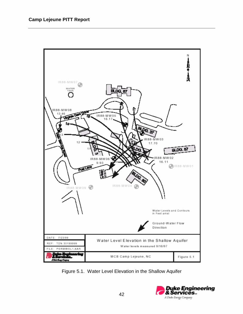
Camp Lejeune PITT Report
42
Figure 5.1. Water Level Elevation in the Shallow Aquifer

Camp Lejeune PITT Report
43
Figure 5.2. Upper Surface of Clay Aquitard Beneath Building 25

Camp Lejeune PITT Report
44
Figure 5.3. Total Thickness of Clay Aquitard Beneath Building 25

Camp Lejeune PITT Report
45
Samples of the clay layer were collected and submitted for vertical hydraulicconductivity, porosity, and capillary pressure testing. Samples from two boringlocations were submitted to PTS Laboratories in Houston, Texas for vertical hydraulictesting; IS22-06 at 21 ft bgs and IS23-04 at 19.5 ft bgs. The averaged results show avertical hydraulic conductivity for the clay layer of 2.0 x 10⁻⁷ cm/sec (5.6 x 10⁻⁴ ft/day)which compares favorably with the 1.0 x 10⁻⁴ ft/day reported in the RI (Baker, 1998a).
Clay samples from the boring at well IN01 were submitted to TerraTek, Salt Lake City,Utah for porosity and capillary pressure tests. The measured porosity for the IN01sample at 21.1 ft bgs was 49.6%. The results of the capillary pressure experiment forthe IN01 sample at 21.0 ft bgs show that the aquitard is an effective capillary barrierthat can support up to 20 ft (6 m) of PCE-DNAPL while allowing negligible DNAPLpenetration.
For further details, see Appendix I, which includes a discussion of capillary effects atDNAPL sites, data analysis and interpretation of the capillary pressure test, andlaboratory reports for the vertical hydraulic conductivity, porosity, and capillary pressuretests.
5.1 DNAPL Distribution
More than 100 soil samples were collected during the investigative phase and analyzedfor the presence of VOCs. These samples were preserved in methanol in the field tominimize losses through volatilization. The results of the soil core VOC andNAPLANAL analysis, as presented in Section 3, reveal trends in the vertical andhorizontal distribution of DNAPL. The majority of the DNAPL was at depths greaterthan 15 ft bgs. The results also indicate that once encountered, DNAPL saturationsincrease with depth until the clay layer (aquitard) is encountered. DNAPL saturationsare generally greatest just above the aquifer/aquitard interface and along the top of theclay layer. Samples collected deeper in the clay exhibit a sharp decline to non-detectwith depth. This supports the assumption that the clay layer is acting as a capillarybarrier, effectively restricting the downward migration of PCE. The occurrence ofDNAPL and Varsol™ in the test zone is shown in Figure 4.4, a generalized crosssection of the geosystem.
The data is consistent with a scenario in which the DNAPL migrated laterally into thetest zone along the sloping surface of an aquitard from a limited number of verticalmigration pathways bringing the DNAPL down from the entry location to the aquitard.DNAPL that migrated into the test zone in this way would be encountered near theaquifer/aquitard interface with little or no DNAPL found higher in the shallow aquifer.The vertical migration pathways are likely beneath the building, outside the test zone.

Camp Lejeune PITT Report
46
6.0 FREE-PHASE DNAPL RECOVERY AT SITE 88
Free-phase DNAPL has been observed in a number of the wells installed at Site 88during the DNAPL source-zone investigations. Recall from Section 1.2 that free-phaseDNAPL is defined as DNAPL existing in the subsurface under a positive pressure suchthat it can flow into a well. In contrast, residual DNAPL occurs at a lower DNAPLsaturation as disconnected ganglia that are held in the pore spaces by capillary forces.Residual DNAPL is not free to flow into a well. Free-phase DNAPL accumulationshould be removed, to the extent possible, from the test zone before conducting a PITTin order to improve the accuracy of the PITT. PITTs are designed to measure thevolume and saturation of residual DNAPL in the test zone and the presence of free-phase DNAPL reduces their accuracy (see Jin et al., 1997).
Table 6.1 lists the wells that have produced free-phase DNAPL and the approximatedepth to the DNAPL/water interface in each well before DNAPL recovery operationswere initiated. Plots of the DNAPL/water interface elevations during all field activitiescan be found in Appendix J.
Table 6.1 DNAPL Levels in Wells at Site 88Well Depth to DNAPL
(ft BTOC)DNAPL Elevation
(ft amsl)Approx. DNAPL Thickness
(ft above top of clay)EX01 17.1 8.5 1.6EX02 20.2 5.4 > 0.3 *IN01 19.4 6.3 0.3HC01 21.0 5.4 > 0.3 *RW01 18.6 6.6 > 0.3 *RW02 18.2 7.2 0.5RW04 17.2 8.6 2.8RW06 16.8 9.7 2.3
* DNAPL was consistently present in these wells, but the measured elevation of the water/DNAPL interface wasequal to or less than the estimated elevation of the clay aquitard. It is not believed that the water/DNAPL interfaceis actually below the clay aquitard. The discrepancy is expected to lie in the soil coring and logging process.When soil cores are retrieved from a borehole for geologic logging (e.g. to determine the depth to clay), therecorded core depth for a given sample has a typical error of approximately ±0.3 ft bgs, and in some cases theerror may be greater when sample recovery is less than 100%. Some error may also be associated with geologicinterpretation.
In February 1998, a DNAPL recovery system was installed to remove as much free-phase DNAPL as possible from the test zone by pumping. Wells EX01, IN01, HC01,RW01, RW04, and RW06 were used as DNAPL recovery wells. The DNAPL recoveryprocess was conducted in two stages. The first stage involved preliminary pumping of

Camp Lejeune PITT Report
47
DNAPL that had accumulated in the recovery wells with a peristaltic pump. Thisprocess began on February 18 and concluded on February 20.
A second stage of the DNAPL recovery process started immediately after completingthe first stage and terminated in late March. It was conducted by pumping the sixDNAPL recovery wells listed above simultaneously in order to create a hydraulicgradient, which would help to induce the free-phase DNAPL to flow to the recoverywells. The pumped fluids were composed primarily of contaminated ground wateralong with a much smaller component of DNAPL. The recovered wastewater/DNAPLwas then transferred to the waste tanker on site. The pumping rate was controlled bykeeping drawdown in the wells to a maximum of about four feet. The combined totalflow from the six recovery wells to the tanker during recovery operations wasapproximately 1.3 gpm.
Attempts to quantify the volume of recovered DNAPL were generally unsuccessful. Aninterface probe was unsuccessful in measuring the depth of accumulated DNAPL in thebottom of the wastewater tanker; this was probably because the DNAPL levels in thebottom of the 8,800 gallon tanker were too shallow to be measured. Grab samples ofeffluent from the recovery wells were also collected in an attempt to volumetricallyquantify the DNAPL recovery rate. Several five-gallon grab samples indicated that theeffluent contained on average about 0.2% DNAPL and 99.8% ground water. However,modeling of DNAPL recovery under the site hydraulic conditions showed that DNAPLrecovery could be expected to decrease over time; therefore, this method ofmeasurement was not considered worthwhile due to the low, decreasing rates ofDNAPL recovery.
Free-phase DNAPL recovery activities continued under water-flooding conditions (i.e.,simultaneous injection and extraction operations) for 14 days during the CITT (April 15-28, 1998) and for 40 days during the PITT (May 13-June 22, 1998). During theseperiods, source water with 1000 mg/L CaCl2 was injected continuously into IN01, IN02,IN03, HC01, and HC02, along with KBr as a tracer during the beginning of the CITT andalcohol tracers during the beginning of the PITT. Pumping was from the six extractionwells (EX01 to EX06), and there was no pumping from RW04 and RW06. CITT andPITT operations are discussed in detail in Sections 9 and 10.
It is believed that the total amount of DNAPL recovered at Site 88 is probably in therange of tens of gallons; about 30 to 60 gallons of DNAPL recovery is likely, andprobably less than 100 gallons. The low permeability of the shallow aquifer greatlylimits the rate at which free-phase DNAPL can be recovered by pumping. However,both free-phase and residual-phase DNAPL can be recovered by SEAR, i.e., theirsolubilization within a microemulsion formed by a surfactant-alcohol micelle and thesolubilized DNAPL (Pope and Wade, 1995). This is the objective of the surfactant floodto be undertaken by the ESTCP team at Site 88 in 1999.

Camp Lejeune PITT Report
48
7.0 LABORATORY STUDIES AND TRACER SELECTION
7.1 Laboratory Scale Studies
This section of the report discusses the results from laboratory studies to measure thepreliminary properties of the Camp Lejeune DNAPL and to select partitioning tracers forthe PITT. All laboratory DNAPL studies discussed below were conducted with aDNAPL sample collected from well RW02, on August 22, 1997.
7.1.1 Preliminary Laboratory Studies
The preliminary studies focused on determining the physical properties of the DNAPL.These were necessary not only for the identification of DNAPL constituents, but also forthe selection of tracers and surfactants. The density of the DNAPL was measured usinga pycnometer; the procedure is included in Appendix K. This measurement was donethree times to ensure repeatability. The density of the field DNAPL sample from Site 88was 1.588 g/cm3. This is very close to the density of pure PCE (1.63 g/cm3) whichsuggests that the DNAPL contained a small fraction of dissolved mineral oils andgrease.
The viscosity of the DNAPL was measured using a Contraves low shear viscometer.The measurement of the viscosity of deionized water was used as a means forensuring quality control. The measured viscosities of the Camp Lejeune DNAPLsample varied between 0.85 centipoise and 1.10 centipoise between shear rates of0.01 sec-1 and 128 sec-1. The viscosity of deionized water under similar conditions wasmeasured at 0.9 centipoise, which agrees with the value reported in the literature.
A spinning drop tensiometer (Cayais et al., 1975) was used to measure the interfacialtension (IFT) between the Site 88 DNAPL and water. This instrument has been usedextensively by the petroleum industry to measure IFTs down to 10-3 dyne/cm. The IFTbetween the Site 88 DNAPL and water was measured at 10.36 dynes/cm. This is muchlower that the IFT between PCE and water of 47.48 dynes/cm (Demond and Lindner1993). This suggests that the DNAPL may have dissolved surface/active agents whichbring about a lowering in the IFT, or that the low IFT is caused by the solubilized oil andgrease noted above.
7.2 Partitioning Tracer Selection
When selecting PITT tracers for field applications, there are a number of tracerperformance criteria that must be met. These include:
• Environmental acceptability

Camp Lejeune PITT Report
49
• Chemical and biological stability
• Insensitivity to small variations in the composition of the DNAPL
• Low detection limits
• Cost effectiveness
• Reasonable market availability
Aliphatic alcohols fulfill all the above performance criteria and are commonly used byDE&S as partitioning tracers. Theoretically, only two tracers, one nonpartitioning andone partitioning, are required for an interwell test. In practice, however, a suite oftracers with different partition coefficients is used to improve the accuracy of the tracertest results. This is especially true when there is a large range of uncertainty in thequantity and distribution of the DNAPL in the pore space to be swept by the test,because the partition coefficient of each alcohol effectively controls how fast that tracermoves across the test zone in the presence of DNAPL. If the residual saturation isknown to be relatively high, tracers with smaller partition coefficients are sufficient, andit is not mandatory to continue the test to obtain the response curves for the tracers withlarger partition coefficients. If the residual saturation is lower than expected, the tracerswith larger partition coefficients can ensure good separation of the tracer responsecurves, thereby giving a better estimate of DNAPL saturation. Aliphatic alcohols fulfillthese criteria and have been used in several PITTs (Jin, 1997a, b; Young et al., 1999;Annable et al., 1998).
This section of the report presents the results of partition coefficient measurementsconducted to identify the partitioning tracers required for the PITT at Site 88. Theobjective of these experiments was to determine the partition coefficients of the alcoholpartitioning tracers between the Site 88 DNAPL and water. This section also containsthe results of a series of soil column partitioning tracer experiments designed toevaluate the performance of each of these candidate partitioning tracers in bothcontaminated and uncontaminated aquifer sediment from Site 88.
7.2.1 Measurement of Static Partition Coefficients
The individual tracers in the PITT tracer suite are chosen on the basis of their partitioncoefficients given the travel time through the swept pore space during a PITT. Thepartition coefficients of the tracers chosen for a PITT should result in a retardationfactor of between 1.2 and 4.0 to obtain good separation of the nonpartitioning andpartitioning tracers for a reasonable test duration (Jin et al., 1995). Previous siteinvestigations in the source area indicate that DNAPL is mainly present on top of thecapillary barrier at the base of the shallow aquifer. Therefore, tracers with largerpartition coefficients were needed for DNAPL estimation since much of the injected

Camp Lejeune PITT Report
50
tracer will flow through the uncontaminated sediment above the DNAPL and berelatively unaffected by the presence of the DNAPL. Static or batch partition coefficientexperiments were conducted with the DNAPL sample from Site 88 and a total of sixaliphatic alcohols were selected. Some experiments were also conducted with stockPCE to ensure quality control of the experimental measurements. This was done toensure that tracers with an acceptably wide range of partition coefficients wereidentified for use in the PITT.
The accurate measurement of tracer partition coefficients is critical for the success of aPITT. The partition coefficient ( Ki ) for a tracer ‘i’ is defined as:
wateri
DNAPLii C
CK
,
,= (7.2.1-1)
where:
DNAPLiC , = equilibrium concentration of the tracer ‘i’ in the DNAPL (mg/L)wateriC , = equilibrium concentration of the tracer ‘i’ in the aqueous phase (mg/L)
The accuracy of the experimental measurements was checked by using the equivalentalkaline carbon number (EACN) approach, developed by Dwarakanath and Pope(1998) to estimate partition coefficients. Both the measured and estimated staticpartition coefficients are presented in Table 7.1. A close match between the measuredand predicted static partition coefficients is observed, within the experimentaluncertainty, suggesting that the accuracy of the partition coefficient measurements wasacceptable.
Table 7.1 Partition Coefficients of Alcohols with Camp Lejeune Site 88 DNAPL
Alcohol Measured PartitionCoefficient
% Uncertainty Estimated PartitionCoefficient
1-Methanol 0.0 -- 0.1
1-Propanol 0.0 -- 0.1
4-Methyl-2-Pentanol 4.2 3.8 4.4
1-Hexanol 8.1 3.6 7.6
2-Ethyl-1-Butanol 6.0 3.9 5.7
5-Methyl-2-Hexanol 24.1 8.7 24.4
1-Heptanol 35.0 9.3 34.5
2-Ethyl-1-Hexanol 115 2.6 115

Camp Lejeune PITT Report
51
7.2.3 Soil Column Experiments
Once the partition coefficients of several candidate partitioning tracers were identifiedusing the static partition coefficient experiments, their behavior in the presence of Site88 soil and DNAPL was evaluated under dynamic conditions in soil columnexperiments. The approach used was to first conduct partitioning tracer experiments incolumns containing uncontaminated shallow aquifer material from the test site at CampLejeune. In these experiments 1-propanol was used as the conservative tracer. Therelative retardation of the partitioning tracers with respect to 1-propanol was measuredand the apparent DNAPL saturation caused by tracer sorption was estimated.Partitioning tracer experiments were then conducted in columns with a known volume ofDNAPL to determine their ability to accurately estimate the volume of DNAPL underdynamic conditions in the presence of Site 88 aquifer sediments. Two columnexperiments in uncontaminated Site 88 sediments and two column experiments inDNAPL-contaminated sediments were conducted to evaluate the performance of thepartitioning tracers. The experimental procedures followed for the soil columnexperiments are presented in Appendix K, as well as the techniques used to analyzethe data from the experiments. The results obtained from the soil column experimentsare presented below.
7.3 Results from Soil Column Experiments
This section discusses the results from laboratory partitioning tracer experiments inboth contaminated and uncontaminated aquifer sediments from Site 88, and discussesthe implications of these results in the analysis and interpretation of field partitioningtracer data.
7.3.1 Partitioning Tracers in Uncontaminated Soil
Partitioning tracer experiments were conducted in uncontaminated soil in columnsCLJ#1 and CLJ#2. The main purpose in conducting these experiments was todetermine whether naturally occurring organic matter would interfere with the accuracyof DNAPL measurement by partitioning tracers. During initial floods through the Site 88soil columns, plugging by clay fines was observed. This problem was alleviated by theaddition of 0.1% CaCl2 to the injected solutions of tracer and water. Thus, in allsubsequent soil column experiments, CaCl2 was included as a constituent of theinjected solution. The tracer response curves for both these experiments inuncontaminated soils are shown in Figure 7.1. Reference to this figure suggests thatpartitioning tracers such as 1-hexanol and 1-heptanol are retarded with respect to theconservative tracer 1-propanol. The heavier alcohol tracers with higher partitioncoefficients show a greater degree of retardation compared to the lighter alcoholtracers. The method of moments, as discussed in Appendix K, was used to estimate

Camp Lejeune PITT Report
52
Figure 7.1. Partitioning Tracer Response in Uncontaminated Soil, Column ExperimentsCLJ#1 and CLJ#2

Camp Lejeune PITT Report
53
the apparent DNAPL saturation and the retardation of the partitioning tracers in thecolumn tests.
Both the tracer retardation and the estimated DNAPL saturation, using the measuredDNAPL partition coefficients, are given in Table 7.2. Based upon these experimentalobservations it is evident that both columns have an apparent DNAPL saturationbetween 0.3% and 0.5%. This apparent detection of DNAPL by the partitioning tracerscan be attributed to the adsorption and retention of the partitioning tracers by thesedimentary organic carbon in the aquifer sediments. Such retention of partitioningtracers has been observed in uncontaminated aquifer material from other sites (Edgar,1997). Interference by sorption to sedimentary organic carbon is typically significant insediments with foc values greater than about 1000 mg/kg (Schwarzenbach and Westall,1981). The foc of Site 88 soil samples used in these column experiments ranged from1200 to 2100 mg/kg, with a visible component present as small peat particles. This willaccount for the observed retardation (Figure 7.1) due to sorption of the partitioningtracers to sedimentary organic carbon despite the absence of DNAPL. A detaileddescription of the retardation of the partitioning tracers by uncontaminated soils inlaboratory column experiments and an experimental correlation between the foc and theretardation of the partitioning tracers is given in Edgar (1997).
Table 7.2 Retardation of Partitioning Tracers in Uncontaminated Camp LejeuneSoil
Column Tracer Retardation Apparent DNAPL Saturation (%)
CLJ#1 4-Methyl-2-Pentanol1-Hexanol1-Heptanol
1.0151.0251.119
0.380.310.34
CLJ#2 4-Methyl-2-Pentanol1-Hexanol1-Heptanol
1.0251.0351.137
0.500.440.39
7.3.2 Partitioning Tracers in Contaminated Soil
Partitioning tracer experiments were conducted in columns CLJ#2 and CLJ#3 after bothcolumns were contaminated with the Site 88 DNAPL. The main purpose of conductingthese experiments was to determine the ability of the partitioning tracers to accuratelyestimate the residual DNAPL saturation. An additional objective of these experimentswas to determine an adequate residence time for the partitioning tracers in thesubsurface. Providing an adequate residence time for the tracers in the subsurfaceduring a PITT is essential because this allows the partitioning tracer molecules topartition into and out of the trapped DNAPL and reach equilibrium. Nonequilibriumpartitioning should be avoided since it can lead to incomplete characterization of the tail

Camp Lejeune PITT Report
54
portions of partitioning tracer breakthrough curves, which can potentially cause errors inestimating the DNAPL saturation.
Based upon mass balance measurements, the DNAPL saturation in column CLJ#2 was5.06%, and 6.35% in column CLJ#3. The response of the partitioning tracers is shownin Figure 7.2. The tracer breakthrough curves show retardation of the partitioningtracers with respect to the conservative tracer 1-propanol. This is an indication of thepresence of DNAPL. The method of moments, as discussed in Appendix K, was usedto estimate the DNAPL saturation. The estimates of DNAPL saturation based upon themethod of moments for columns CLJ#2 and CLJ#3 are given in Tables 7.3 and 7.4. Incolumn CLJ#2, an average DNAPL saturation of 4.42 ± 0.50% was estimated by thepartitioning tracers compared to the mass balance value of 5.06 ± 0.50%. Similarly incolumn CLJ#3, the tracer estimate of DNAPL saturation was 7.21 ± 0.80% compared tothe mass balance value of 6.35 ± 0.50%. Within experimental uncertainty, it is evidentthat the partitioning tracers can accurately determine the residual DNAPL saturation inSite 88 sediments.
Table 7.3 DNAPL Saturation Estimated by Partitioning Tracers, Column CLJ#2Tracer Combination DNAPL Saturation (%)
1-Propanol, 1-Hexanol 4.64 ± 0.551-Propanol, 2,4-Dimethyl-3-Pentanol 4.24 ± 0.461-Propanol, 1-Heptanol 4.40 ± 0.48Average DNAPL Saturation (Tracers) 4.42 ± 0.50Standard Deviation of Partitioning Tracer Estimates 4.2%DNAPL Saturation by Mass Balance 5.06 ± 0.50
Table 7.4 DNAPL Saturation Estimated by Partitioning Tracers, Column CLJ#3Tracer Combination DNAPL Saturation (%)
1-Propanol, 1-Hexanol 7.02 ± 0.851-Propanol, 2,4-Dimethyl-3-Pentanol 7.17 ± 0.791-Propanol, 1-Heptanol 7.45 ± 0.78Average DNAPL Saturation (Tracers) 7.21 ± 0.80Standard Deviation of Partitioning Tracer Estimates 3.0%DNAPL Saturation by Mass Balance 6.35 ± 0.50
These results also indicate that the residence times for the tracers during both theseexperiments are sufficient. The residence times for each tracer in the partitioning tracerexperiments in columns CLJ#2 and CLJ#3 are shown in Table 7.5. The residence

Camp Lejeune PITT Report
FigurExpe
55
e 7.2. Partitioning Tracer Response in DNAPL Contaminated Soil, Columnriments CLJ#2 and CLJ#3

Camp Lejeune PITT Report
56
times varied between 8 hours for the conservative 1-propanol to 26.7 hours for 1-heptanol. However a residence time of 9.5 hours was sufficient for 1-hexanol toaccurately determine the DNAPL saturation in column CLJ#2. This suggests that aresidence time of approximately 10 hours in the subsurface is adequate for equilibriumpartitioning of the tracers.
Table 7.5 Residence Times for Tracers during Partitioning Tracer ExperimentsAlcohol Column Residence Time (hours)
1-Propanol CLJ#2 6.81-Hexanol CLJ#2 9.5
2,4-Dimethyl-3-Pentanol CLJ#2 15.31-Heptanol CLJ#2 17.71-Propanol CLJ#3 7.4
4-Methyl-2-Pentanol CLJ#3 9.71-Hexanol CLJ#3 11.81-Heptanol CLJ#3 26.7
7.4 Tracers Selected for Further PITT Design
Based on the experimental results, and considerations such as cost and availability ofthe various compounds, the following tracers were selected for further PITT design: 1-propanol, 4-methyl-2-pentanol, 1-hexanol and 1-heptanol. More discussion of thetracer properties and quantities applied to the PITT design simulations is provided inSection 8.0.
7.5 Summary and Conclusions
From the results of the partitioning tracer column studies discussed above, it can beseen that retardation of the heavier alcohol tracers such as 1-heptanol inuncontaminated alluvium is greater than the average experimental error of 0.035 in theretardation factor (Dwarakanath, 1997). This is due to sorption of partitioning tracers tosedimentary organic carbon, which occurs primarily as peat particles in the Site 88sediments. The presence of peat leads to a sedimentary organic content that issignificantly greater than the foc typically found in aquifer sediments. The resultingsorption of partitioning tracers to the organic matter results in an apparent DNAPLsaturation of between 0.3% and 0.5% in uncontaminated sediments. However, incontaminated sediments with relatively high DNAPL saturations, i.e., about 5%saturation, this effect was suppressed and no measurable errors were observed in thepartitioning tracer estimate of the DNAPL saturation.

Camp Lejeune PITT Report
57
Based upon the soil column experiments conducted in this study, it can be inferred thatthe presence of DNAPL, at relatively high saturations, masks the effect of sorption bythe organic material and hence can be neglected during the analysis of the partitioningtracer data. A number of wells in the test zone at Site 88, particularly those near thebuilding, showed the presence free phase DNAPL. In these areas it can be assumedthat the retardation of the partitioning tracers is dominated by the presence of highDNAPL saturations and is very weakly affected by the natural organic material. Hencethe effect of retardation by the natural organic material in such areas can be neglectedduring the analysis of the field PITT data.
However, in other areas of the test zone, such as away from the building where DNAPLhas not been observed, the natural organic matter may produce some degree of tracersorption that will show an apparent presence of DNAPL at relatively low DNAPLsaturations of about 0.4%. It is not known at this time what level of actual DNAPLcontamination, i.e., average DNAPL saturation, is needed to dominate the tracerpartitioning response in the presence of the sedimentary organic carbon at Site 88. Soilcolumn testing at lower-level DNAPL saturations, i.e., <3%, is problematic with respectto obtaining an accurate weight (i.e. mass balance) for DNAPL added to a column, andis therefore prone to significant error at low DNAPL saturations.
The partitioning tracers evaluated in both DNAPL-contaminated column tests accuratelypredicted the residual DNAPL saturation. This can be concluded from the closeagreement of residual DNAPL saturations based on mass balance and partitioningtracers. The standard deviation in the tracer estimates of residual DNAPL saturationwas less than 5% in both the partitioning tracer column experiments indicating a highlevel of accuracy of the partitioning tracer method. The excellent agreement betweenmass balance and partitioning tracer estimates of residual DNAPL saturation alsovalidate the accuracy of the static partition coefficient measurements. Finally, for thisgeosystem of alluvium and DNAPL, it can be concluded from the laboratory partitioningtracer experiments that a residence time of 10 hours is sufficient to allow for equilibriumpartitioning of the tracers.

Camp Lejeune PITT Report
58
8.0 PITT DESIGN SIMULATIONS
Successful implementation of a PITT requires the development of an engineeringdesign based on careful and systematic simulations. A good design should minimizethe risk of failure, optimize the information collected, and save time and money.Simulation modeling before field test implementation can provide valuable insight intopertinent design parameters that affect the outcome of the tracer test. These designparameters include: the duration of the tracer test; the amount of tracer mass neededfor injection; the number and configuration of injection, extraction, and hydraulic controlwells; and injection and extraction flow rates for each well. To accomplish this, we usedUTCHEM, which is a multi-component, multi-phase, three-dimensional chemical floodreservoir simulator developed at the University of Texas at Austin. It was originallydeveloped to simulate the surfactant/polymer enhanced oil recovery process (Pope andNelson, 1978; Datta-Gupta et al., 1986; Saad et al., 1990). In the past seven years,enhancements have been made to adapt UTCHEM to simulate both PITT and SEARprocesses (Delshad et. al., 1996). UTCHEM represents the current state of the art forPITT and SEAR design, and has been successfully used by DE&S (formerly INTERA)in the past several years to design numerous PITT, surfactant, and surfactant/foamflood field demonstrations (e.g., INTERA, 1997b; Jin et al., 1997a, b; RICE et al, 1997).
8.1 PITT Design Strategy and Modeling Approach
The first step in designing a tracer test with a numerical simulator is to set up a three-dimensional model of the test zone using an appropriate geometry and grid. Inputparameters to the model should include the best available estimates of the sitegeosystem components, such as the permeability field, porosity, multi-phase fluiddensities and viscosities, dispersivity and other site-specific properties based upon datafrom site investigations or from similar geosystems by analogy. After the model hasbeen developed, a number of sensitivity analysis simulations are conducted to simulatethe performance of the test to provide an optimum design for the PITT. The sensitivityanalysis includes varying the injection and extraction rates, permeability fieldcharacteristics, and the amount and distribution of NAPL, etc. The results from thesesensitivity studies are then used to determine the duration of the tracer test, the mass ofeach tracer needed, the injection and extraction rates, the extraction well effluent tracerconcentrations over time and the cumulative amount of tracer recoverable at the end ofthe tracer test. A preliminary design for the PITT operation is then chosen based uponthe results of these sensitivity studies. The validity of the preliminary design is thentested in the field, before the PITT, by conducting a conservative interwell tracer test(CITT) which uses one or more non-partitioning tracers. The CITT is a relatively short-term test that is used to fine-tune the final PITT design to ensure that a successful PITTwill be conducted.

Camp Lejeune PITT Report
59
The main objectives of the CITT are to:
• Determine the percent recoveries of the tracer at each well
• Determine the actual residence times of the tracers in the subsurface
• Determine the actual swept pore volume to finalize the PITT design
• Determine the effective permeability of the aquifer
• Obtain insights into the relative heterogeneity of the aquifer and a betterunderstanding of the subsurface flow system
• Act as a shakedown for the ensuing PITT in terms of equipment setup, samplecollection, well monitoring, etc.
Based on the objectives of the CITT, it is evident that the model predictions for theCITT do not need to be precise. The information gained from the CITT is of great valuein making final decisions on the PITT design. CITT results are used to update andcalibrate the geosystem model. Then, a number of numerical simulations, for sensitivityanalysis, are conducted to study the behavior of different partitioning tracers in order toformulate an optimum final design for the PITT. The results of these post-CITTsensitivity analyses are then used to:
• Finalize the selection of the tracers
• Determine the duration of the PITT
• Determine the mass of each tracer needed
• Determine the injection and extraction rates
• Determine sampling frequency at monitor and extraction wells
• Predict the swept volume
• Predict the extraction well effluent tracer concentrations
• Predict the amount of tracer recovered by the end of the tracer test

Camp Lejeune PITT Report
60
8.2 Simulation Model Development
8.2.1 Well-Field Configuration
Preliminary UTCHEM simulations based on site hydrogeological data, indicated that thePITT well field would be most efficiently configured with a divergent line-drive geometry,i.e., a line of injection wells flanked on both sides by lines of extraction wells. In order tomaintain hydraulic control and to ensure that an adequate portion of the well field will beswept, each injection or extraction well is spaced 10 ft from its nearest neighbor within aline of injection or extraction wells. The interwell distance between any pair of injectionand extraction wells is 15 ft. This corresponds to a well-field size of 20 ft by 30 ft. Thewell-field configuration is shown schematically in Figure 4.1. As the figure shows, thewell field consists of 11 wells. There are six extractors and three injectors. In addition,a hydraulic control well is located outside the well field on each end of the line ofinjection wells. These two wells are used only as hydraulic control wells (i.e., only waterwill be injected into these wells during flooding operations) to provide hydrauliccontainment of the tracer flowpaths between injection and extraction wells. Tracerinjection at the center of the well-field panel, with simultaneous extraction on both sidesof the well-field array, drives the tracer injectate divergently outward towards theextraction wells where tracer recovery occurs.
8.2.2 Simulation Domain
The plan view of the three-dimensional UTCHEM model grid is illustrated in Figure 8.1.The figure also shows the locations of the injection wells, the extraction wells, and theelevation contours defining the top of the clay aquitard. The aquifer volume in the testzone was simulated using a three-dimensional 25 X 25 X 16 mesh consisting of a totalof 10,000 grid blocks. The horizontal extent of the model was 141 ft long, and 99 ftwide. The vertical extent of the model was 13 ft thick to represent the saturatedthickness of the test zone, and corresponds to a bottom elevation of about 5 ft amsl,and a top elevation of 18 ft amsl. This overall vertical thickness of 13 ft was divided into16 layers with a uniform thickness of 0.5 ft per layer for the bottom 12 layers. The clayelevation contour of the aquitard was incorporated into the model by mapping all gridcells with centroid locations below the surface of the aquitard (as defined by the krigedelevations shown in Figure 8.1 as clay blocks), effectively making them no-flowboundaries. The simulation dimensions and the number of gridblocks were chosen tominimize boundary effects. No-flow boundary conditions were assumed for the top ofthe simulation domain. The pressures at two outer boundaries were kept constant toestablish a regional hydraulic gradient of 0.015.

Camp Lejeune PITT Report
61
Figure 8.1. Plan View of the Simulation Grid and Aquitard Elevation Contour

Camp Lejeune PITT Report
62
8.2.3 Physical Properties of Porous Media and Fluids
The porous media and fluid physical properties used in our model were based upondata from the site investigations or from similar geosystems by analogy. The values forsome of the properties are provided below.
porosity 0.34average permeability 0.4 darciesdensity of water 1 g/cm3
density of NAPL 1.63 g/cm3
water-NAPL interfacial tension 45 dynes/cmNAPL viscosity 0.89 cpwater viscosity 1.0 cp
Values for relative permeability and capillary functions were taken from the literaturebased on data from similar sites. It should be noted, however, relative permeability andcapillary functions are not very important parameters for the PITT since the process isessentially single-phase flow with the second phase as residual NAPL. The capillarypressure equals zero in this case. The initial NAPL saturation distribution was based onthe soil sampling analytical data. A NAPL saturation of 10% for the bottom two feet ofthe aquifer was used for the simulations. Observations of soil cores also indicated thatthe permeability at the bottom portion of the shallow aquifer is significantly lower thanthe main portion of the aquifer, as discussed in Section 5.0. This vertical heterogeneitywas addressed in the model by assigning a permeability contrast of 2 between theupper intervals versus the bottom portion of the model.
The tracers used for the simulations are based on the laboratory column experiments.The tracers and their measured partition coefficients are listed in Table 8.1.
Table 8.1 Tracers and their Partition Coefficients
Tracer Name Partition Coefficient
1-Propanol 0
4-Methyl-2-Pentanol 4
1-Hexanol 8
1-Heptanol 35

Camp Lejeune PITT Report
63
8.3 CITT Design
As discussed in Section 8.1, a number of sensitivity analyses were run to simulate theperformance of the tracer test in order to provide an optimum design for the PITT. Thesensitivity analyses included varying the injection and extraction rates and permeabilitydistribution, etc. The results generated from these simulations were used to design theCITT. Tables 8.2 and 8.5 summarize the pertinent CITT design variables. Thepredicted tracer response curve for a conservative tracer at each of the extraction wellsis shown in Figure 8.2. The simulation predictions, in terms of swept pore volume, thepercentage of tracer recovered, and the tracer residence times for each extraction well,are given in Table 8.6. The predicted tracer recovery was approximately 90%. Thepredicted swept aquifer pore volume was approximately 4,920 gallons after 14 days oftracer operation. The actual results, including the predicted tracer response curves ateach well, may vary somewhat for a variety of reasons such as the uncertainty in theaquifer permeability field, i.e., heterogeneity. However, the CITT can be successfulover a wide range of uncertainties since the purpose of the CITT is to obtain anunderstanding of how an induced-flow system behaves in the test zone site. The CITTdata was used to calibrate the numerical model for the final PITT design simulations.
Table 8.2 Design Summary of CITT Flow Rates Well Type Well Name Flow Rate (gpm) Total (gpm)
EX1 0.25 EX2 0.25 EX3 0.25
EX4R 0.25 EX5 0.25
Extraction
EX6 0.25
1.5
IN1 0.2 IN2 0.2 Injection IN3 0.2 HC1 0.3
Hydraulic Control HC2 0.3
1.2

Camp Lejeune PITT Report
64
Figure 8.2. Prediction of CITT Tracer Response
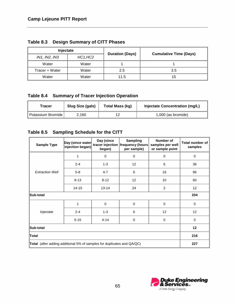
Camp Lejeune PITT Report
65
Table 8.3 Design Summary of CITT Phases Injectate
IN1, IN2, IN3 HC1,HC2 Duration (Days) Cumulative Time (Days)
Water Water 1 1 Tracer + Water Water 2.5 3.5
Water Water 11.5 15
Table 8.4 Summary of Tracer Injection Operation
Tracer Slug Size (gals) Total Mass (kg) Injectate Concentration (mg/L)
Potassium Bromide 2,160 12 1,000 (as bromide)
Table 8.5 Sampling Schedule for the CITT
Sample Type Day (since waterinjection began)
Day (sincetracer injection
began)
Samplingfrequency (hours
per sample)
Number ofsamples per wellor sample point
Total number ofsamples
1 0 0 0 0
2-4 1-3 12 6 36
5-8 4-7 6 16 96
9-13 8-12 12 10 60
Extraction Well
14-15 13-14 24 2 12
Sub-total 204
1 0 0 0 0
2-4 1-3 6 12 12Injectate
5-15 4-14 0 0 0
Sub-total 12
Total 216
Total (after adding additional 5% of samples for duplicates and QA/QC) 227

Camp Lejeune PITT Report
66
Table 8.6 Summary of CITT Simulation Predictions Well Name Tracer Recovery (%) Swept Volume (gals) Mean Tracer Residence Time (days)
EX1 10 570 7.0 EX2 19 1,230 7.7 EX3 7 460 7.4 EX4 20 920 5.3 EX5 23 1,170 6.0 EX6 11 570 5.7 Total 90 4,920
8.4 PITT Design
As might be anticipated, the actual CITT response curves differed from the modelprediction. The detailed CITT results are presented in Section 11.3. A comparison ofTable 8.6 and Table 11.1 indicates that the model prediction and the actual results werein good agreement; therefore, the geosystem model was a reasonable representationof the actual aquifer. Nonetheless, the geosystem model was updated with the resultsof the CITT to further refine the model for the PITT design simulations. The mostimportant adjustment made to the geosystem model for the PITT design was to focusthe tracer flowpaths along the bottom portion of the aquifer where the DNAPL residesthrough the use of a dual injection system. The dual injection design provides verticalhydraulic control of tracer flowpaths, and is described as follows. At each of the threeinjection wells, clean, tracer-free water was injected into the upper screen only (abovean inflatable packer), along with the simultaneous injection of tracers below the packerinto the lower screen (see Figures 4.2 and 4.4 for injection well configuration). The dualinjection system also prevented tracer flowpaths from moving upwards through theLNAPL (Varsol™) smear zone which coincides with the fluctuating water table(Figure 4.4). If tracer flowpaths were allowed to travel through the LNAPL zone, therewould be interference with partitioning of tracers occurring in both the LNAPL andDNAPL zones. This interference between the LNAPL and DNAPL zones wouldtherefore increase the difficulty of analyzing the PITT data in order to obtain meaningfulinformation with respect to the DNAPL zone. Before considering the dual injectionscheme, PITT flow rates were designed for overproduction during the PITT, i.e., greatertotal extraction rates than total injection rates. Overproduction has the potentialundesirable effect of declining flow rates over time at the extraction wells (i.e., due todewatering the test zone). However, the addition of upper-level water injectionimproved the balance of flow between total injection rates and total extraction rates,and minimized the potential for dewatering at extraction wells during the PITToperation.

Camp Lejeune PITT Report
67
As in the design of the CITT, sensitivity simulations were conducted to provide anoptimum design for the PITT. Tables 8.7 through 8.10 summarize the pertinent designvariables for the PITT, based upon the calibrated geosystem model and the sensitivitystudies. The predicted tracer response curves for all of the extraction wells are shownin Figures 8.3 through 8.5. The simulation predictions are summarized in Table 8.11 forswept pore volume, percentage of tracer recovered, and the interwell residence times(i.e., tracer travel time between an injection and extraction well pair).
Based on the results of multiple sensitivity simulations, the predicted tracer recovery atthe end of the PITT was expected to be approximately 93% to 96%. The predictedswept aquifer pore volume, based on the simulated tracer response analysis, wasapproximately 6,450 gallons. The actual PITT results varied for a number of reasons,including the uncertainties in the degree of aquifer heterogeneity and the distribution ofDNAPL in the swept pore volume. This is discussed in further detail in Section 11.4.
Table 8.7 Design Summary of PITT Flow Rate Well Type Well Name Flow Rate (gpm) Total (gpm)
EX1 0.25 EX2 0.25 EX3 0.30 EX4 0.25 EX5 0.25
Extraction
EX6 0.25
1.55
IN1-lower 0.2 IN2-lower 0.2 IN3-lower 0.2 IN1-upper 0.08 IN2-upper 0.08
Injection
IN3-upper 0.08 HC1 0.3
Hydraulic Control HC2 0.3
1.44

Camp Lejeune PITT Report
68
Figure 8.3. Prediction of Extraction Wells EX01 and EX02 Tracer Response

Camp Lejeune PITT Report
69
Figure 8.4. Prediction of Extraction Wells EX03 and EX04 Tracer Response

Camp Lejeune PITT Report
70
Figure 8.5. Prediction of Extraction Wells EX05 and EX06 Tracer Response

Camp Lejeune PITT Report
71
Table 8.8 Design Summary of PITT Operation Phases Injectate
IN1, IN2, IN3 HC1,HC2, IN1-upper,IN2-upper, IN3-upper
Duration (Days) Cumulative Time (Days)
Water Water 1 1 Tracer + Water Water 5.8 6.8
Water Water 34.2 41
Table 8.9 Summary of Tracer Injection Operation Tracer Name Partition Coefficient Total Mass (kg) Injectate Concentration (mg/L)
1-Propanol 0 19 1,000 Methanol 0 19 1,000
4-Methyl-2-Pentanol 4 19 1,000 1-Hexanol 8 19 1,000 1-Heptanol 35 13 700
Table 8.10 Sampling Schedule for the PITT
Sample Type Day (since waterinjection began)
Day (sincetracer injection
began)
SamplingFrequency (hour
per sample)
Number ofSamples per Wellor Sample Point
Total Number ofSamples
1 0 0 0 0
2-7 1-6 6 24 144
8-13 7-12 12 12 72Extraction Well
14-41 13-40 24 28 168
1 0 0 0 0
2-7 1-6 8 18 54
8-13 7-12 12 12 36
Multilevel Sampler(only three out of nine
sample ports werefunctioning during the
PITT) 14-41 13-40 24 28 84
Total Extraction Well and Multilevel Sampler Samples 558
1 0 0 0 0
2-7 1-6 6 24 24Injectate8-41 7-40 0 0 0
Total Injectate Samples 24
Sub-Total 582
Total (after adding additional 20% of samples for duplicates and QA/QC) 700

Camp Lejeune PITT Report
72
Table 8.11 Summary of PITT Simulation Predictions Well Name Tracer Recovery (%) Swept Volume (gals) Mean Residence Time (days)
EX1 9 660 8
EX2 22 1,800 9
EX3 10 940 10
EX4R 18 920 6
EX5 24 1,400 7
EX6 13 730 6
Total 96 6,450

Camp Lejeune PITT Report
73
9.0 CONSERVATIVE INTERWELL TRACER TEST (CITT)
This section provides the operational details and test results for the conservativeinterwell tracer test (CITT) performed during April 15–28, 1998, using design flow ratesobtained from preliminary UTCHEM modeling. The objectives of this test were todetermine the average subsurface tracer residence times, tracer swept pore volumesfor each of the interwell pairs, and as otherwise discussed in Section 8.1 (PITT DesignStrategy and Modeling Approach). These results were then used to update theUTCHEM model for the final PITT design simulations. A general layout of the testsystem is shown in Figure 9.1. Tracer and water-flood solutions were mixed in thestorage tanks and then injected into the aquifer via the autocollector/control trailer.Packers were installed in the injection and hydraulic control wells for the purpose ofseparating the upper and lower screens. The tracer injection line was run through thepacker to direct flow through the lower screen into the lower zone of the shallow aquifer.Injectate flowing to the extraction wells was then pumped from the wells to the wastetanker via the autocollector/control trailer.
The purpose of autocollector trailer and the data acquisition system (DAS) was tocollect samples, control and log injection flow rates and monitor water levels. Flow rateand water level data was electronically recorded once every 20 minutes.
Injection flow rates were manually measured daily using a stopwatch and graduatedcylinder. Each manual measurement was compared to the DAS-recorded flow rate. Ifthe flow rate varied by more than 10%, the appropriate electronic flow meter wasrecalibrated. Extraction well flow rates were not monitored with conventional flowmeters because the pneumatic pumps provide a pulsed flow. The flow rates in theextraction wells, therefore, were determined by monitoring flow totalizers and elapsedtime.
Water levels in the extraction wells and lower zones of the injection wells wereelectronically measured and recorded by the DAS. Manual measurements taken with awater level meter were compared to the DAS data; if significant deviations wereobserved, then corrective action was taken (e.g. replacement or recalibration oftransducers) to correct the discrepancies Water levels were also measured in theupper zones of the hydraulic control wells and injection wells and in selected monitorwells.
On April 14, 1998 a CITT was initiated and conducted in the following sequence:
1. pre-injection water flood,
2. conservative tracer injection, and
3. post-injection water flood.

Camp Lejeune PITT Report
74
Figure 9.1. PITT Site Map

Camp Lejeune PITT Report
75
The pre-injection water flood started 24 hours before tracer injection to establish asteady-state flow regime in the well field. A tracer slug of approximately 2,100 gallonsof approximately 970 mg/L of bromide ion (Br-) was injected over a 59-hour period.Tracer injection was followed by 12 days of water flooding to transport the tracerthrough the zone of interest. These phases were conducted using the design extractionand injection flow rates summarized in Table 8.1. The total CITT duration was abouttwo weeks.
All water injected during the test contained CaCl2 at a concentration of approximately1,000 mg/L. This was done to decrease the probability of clay particle mobilization dueto ion exchange in the aquifer sediments. Mobilization of these fine clay particles couldhave resulted in significant pore-plugging, thereby reducing the hydraulic conductivityand thus the sustainable flow rates at the injection and extraction wells. Injectatebatches were checked with a conductivity probe before injection to ensure that theCaCl2 concentration was within acceptable limits.
Effluent samples were collected manually from each extraction well according to thesampling schedule in Table 8.5, and analyzed for Br- concentration. Concentrationswere measured using an Orion Model 9435BN bromide selective electrode and model900200 double junction reference electrode connected to an Orion Model 250A pHmeter. The analysis was carried out using the DE&S standard operating procedureoutlined in Appendix L.
The Br- tracer concentration histories are plotted in Figure 9.2 to show the tracerresponse at the six extraction wells. The Br- tracer response data was then normalized(to the Br- injectate concentration) for the CITT data analysis. The normalized tracerresponse data and their corresponding fitted curves, (based on Equation 11.2-2 inSection 11.3) are shown in Figures 9.3a to 9.3c for the six extraction wells. The tracercurves were analyzed using the method of temporal moments (which is discussed inSection 11.1; PITT Data Analysis). The resulting estimates of the tracer recovery,swept volume, and mean residence time for each well are summarized in Table 11.1.The total aquifer pore volume swept by the tracers was approximately 4,810 gallons asdetermined by adding up the swept volumes calculated for each well.
Based upon the results from the CITT, the geosystem model used was then calibratedto reflect more closely the actual test domain and was used to design the PITT asdescribed in Section 8.4.

Camp Lejeune PITT Report
76
Figure 9.2. CITT Bromide Break-Through Cu
rves
Camp Lejeune PITT Report
77
Figure 9.3a. CITT Tracer Response at Extraction Wells EX01 and EX02

Camp Lejeune PITT Report
78
Figure 9.3b. CITT Tracer Response at Extraction Wells EX03 and EX04R

Camp Lejeune PITT Report
79
Figure 9.3c. CITT Tracer Response at Extraction Wells EX05 and EX06

Camp Lejeune PITT Report
80
Table 9.1 Summary of CITT Results
Well Name Tracer Recovery (%) Swept Volume (gallons) Mean Residence Time (days)
EX1 14.5 800 6.4
EX2 20.8 1,230 6.8
EX3 6.7 390 6.6
EX4R 16 910 6.5
EX5 16 1,000 7.3
EX6 8. 480 6.9
Total 82.0 4,810
To minimize the movement of tracers vertically upward towards the water table and theassociated LNAPL smear zone, a dual injection system was recommended andimplemented for the PITT. In addition, the extraction rates were also slightly adjustedto balance the uneven tracer mass recovery observed in the CITT. The PITT results,as presented in Section 11.0, support the conclusion that the information gained fromthe CITT was of great value in making final decisions on the PITT design.

Camp Lejeune PITT Report
81
10.0 PITT FIELD IMPLEMENTATION
This section provides an overview of the actual field implementation of the PITT.Included in the discussion is a chronological description of the main events involved inthe conduct of the test and the main sampling events. A more detailed description ofthe actual field activities and sampling events can be found in the Work Plan and theSampling and Analysis Plan (DE&S 1998a; DE&S 1998b).
The test system was shut down after completion of the CITT to perform generalmaintenance, install system upgrades, and make modifications to accommodate therecommendations for the final PITT design. The final PITT design required that threeadditional injection lines be added to facilitate upper hydraulic-control injection into theupper screen intervals of the three IN wells. Injection of tracer-free water into the upperzone was intended to keep the tracers from flowing through the Varsol™ NAPL zone bymaintaining hydraulic control of the upper section of the aquifer.
10.1 PITT Operations
The tracer solution, which contained both non-partitioning and partitioning tracers, wasprepared by filling 3,000 gallon tanks with 2,500 gallons of potable water and thenadding the tracers in four liter increments. Two tracer batches were mixed in separatetanks resulting in a tracer slug of about 5,000 gallons. Table 10.1 provides a list of thetracers mixed in the batch, the volume added per tank and the approximate finalconcentrations. The heavier or longer-chained alcohols, such as heptanol, have lowaqueous solubilities and therefore, do not readily mix with water. After adding thealcohols to the tank, an alcohol phase was clearly seen floating on top of the water.The alcohols were completely mixed into solution by recirculating the water in the tanksuntil there was no visible evidence of an undissolved alcohol phase. Mixing wasconsidered complete after approximately two days of recirculation.
Table 10.1 Tracer Volumes and Approximate Concentrations per Tank
Tracer Volume added/Tank Concentration (mg/L)1-Propanol 12 liters 1,000Methanol 3 gallons 950
4-methyl-2-Pentanol 12 liters 1,0001-Hexanol 12 liters 1,0001-Heptanol 8 liters 700

Camp Lejeune PITT Report
82
To avoid tracer concentration fluctuations in the injectate it is important that the tracerbatch be completely homogenous. To achieve this, the tanks were cross-mixed afterthe alcohols had been dissolved into solution. Cross mixing was accomplished byinserting the “Tank A” recirculation line into “Tank B” and placing the “Tank B”recirculation line into “Tank A”. The tanks were mixed in this manner for approximately24 hours.
During the interim period between the completion of the CITT and the start of the PITT,the upper zone injection system was installed and maintenance tasks were completedon the test system. Upon completion of these interim activities, in preparation for thePITT, the test system was brought back on line. A water flood was started using thedesign flow rates as outlined in Table 8.7 to establish a steady-state flow field beforeinitiating tracer injection. On May 13, 1998 following 24 hours of water flooding, tracerinjection was begun. Tracer injection continued for a period of approximately five days,which was then immediately followed by 35 days of water flooding. The total duration ofthe PITT was 40 days; the test was terminated on June, 22 1998.
During the test, flow rates and water levels were controlled, monitored and logged asdescribed in Section 9.0 regarding CITT operations. In addition, during the PITT theupper injection zone system was also electronically controlled by the DAS. Plots of flowrates, cumulative volume and water levels are given in Appendix M. These figuresshow that flow rates and water levels remained stable throughout the duration of thetest.
10.2 PITT Tracer Sampling
As part of the PITT procedure, samples of the injectate, extraction-well effluent andfrom the multilevel samplers (MLS) were collected and analyzed for tracerconcentrations. Injectate and extraction-well samples were collected in 22-mL glassjars capped with Teflon-lined caps. MLS samples were collected in 5-mL vials, alsowith Teflon-lined caps. All samples were stored in a refrigerator at 4oC.
Injectate samples were taken at various times during tracer injection to verifyhomogeneity of the tracer slug. An injectate sample was taken 15 minutes before and15 minutes after tracer injection had begun. The injectate was then sampled at a rateof one sample per day until injection ended. Finally, samples were collected fiveminutes before injection terminated, and also five and 20 minutes after injectionterminated. Samples were taken from a sampling port that had been installed in theinjection line.
Effluent samples were collected by the autocollector following the sample scheduleoutlined in Table 8.10. Manual samples were also taken as backup samples at one half

Camp Lejeune PITT Report
83
the automated sampling rate. Duplicates and equipment blanks were taken at a rate ofone for every 20 samples collected.
Obtaining sufficient flow from the multilevel sampling points proved to be problematic.After repeated sampling attempts, flow could only be established in three of the ninesampling ports - specifically, MLS-2 at 17.0 ft and 18.5 ft bgs, and MLS-3 at 17.5 ft bgs.Samples were collected at these points following the schedule outlined in Table 8.10.
Samples to be analyzed for tracer concentrations were packed in coolers with ice andshipped to Mantech Environmental of Ada, Oklahoma. A trip blank prepared withdiagnostic-grade water was placed in each cooler.
10.3 PITT Tracer AnalysisThe PITT samples were analyzed for tracers by a gas chromatography (GC) methodwhich initially involved direct injection onto a capillary column. The Standard OperatingProcedure (SOP) for GC Analysis of Alcohol Compounds in Water Samples, byMantech is in Appendix O. However, this very quickly created severe fouling of thecapillary column, which is most likely attributed to the calcium content of the samplesfrom CaCl2 injection with the tracers. After several attempts to salvage this method byregenerating the capillary column and even by replacing it, the method was abandoned.Several options were explored, including a full evaporation GC technique that would notinvolve direct injection and also a high pressure liquid chromatography (HPLC) method.Finally it was decided to switch to direct injection onto a packed column. This methodwas successful, and was used on all samples analyzed after May 28, 1998, whichapproximately corresponds to PITT samples collected after May 17, 1998 (four daysafter the PITT was initiated). No more fouling difficulties were encountered with the useof the packed column; however, the new method raised the tracer detection limits from1 ppm to 5 ppm for all tracers except for 1-heptanol, which could only be quantifiedaccurately to 10 ppm with the packed column. The time spent exploring alternativeanalytical methods and developing the packed column method also created a backlogof samples to be analyzed (see Section 11.1.1 for more details). Full details of theanalytical methods used for tracer analyses are provided in Appendix Q.
10.4 Water Quality Monitoring
In addition to the samples collected for tracer analysis, various water quality parameterswere also monitored as part of the PITT operations. Also, temperature, pH andconductivity were measured at many locations in the well field for input requirements tothe SEAR design process.
A small amount of arsenic (≅ 3mg/kg) contamination was present in the dry, granulatedcalcium chloride used to make the water-flood solutions. Since CaCl2 was injected at

Camp Lejeune PITT Report
84
0.1 wt%, arsenic concentrations in the injected solution did not exceed3 µg/L. Perimeter monitor wells were sampled and analyzed to detect potentialincreases in arsenic levels that occurred during the PITT. Monitor wells were alsosampled for tracer concentrations to verify that hydraulic control was maintainedthroughout the test and that tracers did not migrate beyond the confines of the testzone.
Samples were collected from wells IW01, RW01, RW02, RW04 and the six extractionwells for field measurement of pH, conductivity, and temperature. The data was usedin the design of the surfactant flood and wastewater treatment system. The sixextraction wells were sampled two to three times per week and the remaining monitorwells were sampled weekly. The pH was measured with an Orion Model 250A pHmeter, and the conductivity and temperature was measured with a conductivity probe.The data for these field-measured parameters are presented in Appendix N.
Extraction well samples were collected from sampling tees in the autocollector trailer.Sample lines were purged before sample collection to prevent cross contamination.Monitor well samples were collected using a peristaltic pump. Samples were takennear the bottom of the well bore and at various depths to determine if any concentrationgradients existed in the wells. The data is presented in Appendix N.
Monitor wells MW02 and MW02IW were sampled on a weekly basis and analyzed forthe presence of tracers to determine if injectate was escaping from the test zone. Inaddition, samples were collected from MW02, MW03 and MW05 before, during andafter test completion to monitor arsenic levels in the aquifer. The resulting data can befound in Appendix O.
All monitor well samples were collected with a peristaltic pump following the monitorwell sampling procedure outlined in Appendix L.

Camp Lejeune PITT Report
85
11.0 PITT RESULTS AND DATA ANALYSIS
The field measurements and tracer breakthrough curves collected from the PITT andthe significance of these results are discussed in this section. The method of analysisapplied to the interpretation of the tracer data is also briefly discussed.
11.1 Laboratory Analytical Results
11.1.1 PITT Samples
As discussed in Section 10.3, all PITT samples were analyzed for tracers by directinjection on a GC. Initially, tracer analysis included methanol, but due to analyticalproblems, including those discussed below, it was decided to discontinue analyzing formethanol. Since methanol was injected as a backup conservative (i.e., non-partitioning) tracer to 1-propanol, and no difficulties were encountered with analysis of1-propanol, this has not affected the PITT results. PCE concentrations were alsoobtained for some PITT samples. The complete PITT data set is included in AppendixO.
Several difficulties were encountered during the analysis of the PITT samples. Alreadymentioned was fouling of the capillary GC column, which created the need to switch toa packed column to analyze PITT samples collected after day four of the PITT. TheSOP for the GC analytical method shown in Appendix O indicates the capillary columnhad a quantitation limit of approximately 1 ppm whereas the tracers analyzed by packedcolumn had a quantitation limit of approximately 5 ppm. Fouling of the GC column hadnot been detected during GC method development efforts conducted prior to the PITT.During method development activities, tracer solutions were made up with site groundwater and CaCl2, but column fouling was not observed to occur until numerous columninjections were made for analysis of the PITT samples. Fouling of the capillary columnis most likely attributed to the dissolved CaCl2 that was included in the PITT injectatesolution to prevent the mobilization of soil fines in the aquifer. The GC fouling problemscreated a backlog of samples and resulted in the 7-day sample holding time to beexceeded for as many as 70% of the samples collected during the first 15 days of thePITT. The conventional holding time for VOC samples is seven days without samplepreservation and 14 days with sample preservation. When fouling problems came to ahead, sample preservation was adopted in the field, on Day 16 of the PITT (May 29,1998), by adding 1% HCl to all PITT samples to extend the sample holding time to 14days. Fortunately, the missed sample holding times did not significantly affect theaccuracy of the analytical results. Follow-up laboratory studies to evaluate the effect ofmissed holding time showed that there was no statistically significant difference in thetracer concentrations obtained between samples analyzed within their holding time and

Camp Lejeune PITT Report
86
up to two weeks beyond their holding time. A summary of the holding-time study isprovided in Appendix P.
A related analytical issue involved quantifying peak tracer concentrations, whichsometimes exceeded the maximum tracer detection limit of approximately 200 ppm,and therefore required dilution and reanalysis. Due to the backlog of PITT samples, thereanalysis of such samples was performed three weeks after the initial analysis. Insome of these samples, the final analytical result after dilution and reanalysis was ≤ 200ppm. This decrease in the analytical result for tracer concentrations, between theoriginal sample analysis and the later reanalysis, is suspected to have resulted in anunderestimate to some degree of the actual tracer concentrations. The effects of thispossible analytical issue on the PITT results are discussed in Section 11.4.3.
Finally, the increase in the quantitation limit to 5-10 ppm, caused by the modification ofthe analytical method (from a capillary column to a packed column), truncated theuseful data set to some degree for all tracers in the tail region of the tracer curve. Theeffect of this is discussed in Section 11.2.
11.1.2 Monitor Well Samples
Several perimeter monitor wells were sampled for tracers and also for arsenic, duringand on completion of the PITT. Wells MW02 and MW02I were sampled for traceranalysis, and wells MW02, MW03, and MW05 were sampled for arsenic analysis. Theanalytical results for these perimeter monitor points are included at the end of the PITTanalytical results in Appendix O.
Most of the tracer analyses in these perimeter monitor wells were below detectionlimits. In a few of the samples (4 out of 46), tracer was detected at ppm levels, whichcan be attributed to carryover in the GC column (i.e., carryover from the previoussample analysis) since carryover was also observed in a similar percentage of methodblank analyses.
The analytical results for arsenic were below detection limits (<5 ppb) for all of thearsenic monitoring samples.
11.2 Tracer Data Analysis Approach
The first step in the PITT data analysis process was a Quality Assurance/QualityControl (QA/QC) evaluation of the PITT dataset. The QA/QC process is necessary tovalidate the PITT data for interpretation of the PITT. The PITT data QA/QC report ispresented in Appendix O, along with the PITT dataset.
To ensure the quality of the data used for DNAPL volume estimation, tracer data thatdid not meet QA/QC criteria were eliminated from the data base. The tracer data

Camp Lejeune PITT Report
87
QA/QC process also excludes the tracer data in which the measured concentrations arebelow the detection limits of the GC method of analysis. The reported GC detectionlimits were about 5 mg/L for all the tracers except 1-heptanol, which was about10 mg/L. Figure 11.1 provides a visual comparison of the complete tracer dataset(upper plot) versus the tracer data that was used for analysis of the PITT (lower plot).The tracer data for 1-propanol that lie along the detection limit line (upper plot) were notused in the PITT analysis since the concentrations at that point were at the quantitationlimit, and we could not have confidence in the accuracy of the data. Therefore, thecurve fit for 1-propanol is based upon an extrapolation of the data below thequantitation limit, as shown in the lower plot in Figure 11.1.
The second step of the data analysis process is to evaluate the available field data andselect a pair of non-partitioning and partitioning tracers to use for DNAPL volume andsaturation estimation. Theoretically, each pair of non-partitioning and partitioning tracerdata can give an independent estimate of DNAPL volume and saturation. From apractical standpoint, however, the retardation factor should be greater than 1.2 in orderto increase the estimation accuracy (Jin,1995). The conservative tracer used for thePITT data analysis was 1-propanol. As shown in Figure 11.2, the tracer separationbetween 1-propanol and 4-methyl-2-pentanol (4M2P) is too small to provide anaccurate estimate of DNAPL saturation. In general, the retardation factor of 4M2P fromthis tracer test was smaller compared with 1-hexanol and 1-heptanol. Therefore, thetracer data of 4M2P was not used for the data analysis.
The third step is to fit the tracer response data with smooth curves and estimate theDNAPL volume and saturation as a function of tracer cutoff time. The estimatedDNAPL volume and saturation should approach a plateau (not shown, see Jin et al.,1997b, Figure 9) as the tracer test approaches completion. For this tracer test, theanalysis was done by fitting the tracer response data using the following exponentialdecline equation,
))ln(()(1
tctbaExptC i
in
ii ++=
=
(11.2-1)
where n is the number of peaks observed in each individual tracer response curve andai, bi, and ci are the corresponding fitting parameters. In most cases, there is only onepeak in a tracer response curve and the correlation equation (1) can be simplified to
))ln(/()( tctbaExptC ++= (11.2-2)
The fitting of the tracer data to the above equation also provides a unique way ofestimating the uncertainty of the estimated DNAPL saturation from a given set of GCmeasured tracer data. The standard error of DNAPL saturation estimation from a PITT

Camp Lejeune PITT Report
88
Figure 11.1. Example of QA/QC of Tracer Data

Camp Lejeune PITT Report
89
Figure 11.2. Comparison of Degree of Separation of Tracer Response at EX01

Camp Lejeune PITT Report
90
can be estimated based on the standard errors of the fitting parameters, and theDNAPL saturation estimation accuracy can be increased by increasing the accuracy ofthe curve fitting parameters. Figure 11.3 shows an example of the fitting parametersand the corresponding standard errors of the 1-propanol response curve for extractionwell EX1.
Because the tracer concentration and the flow rate data were not recorded at the sametime, a separate program was used to convert the tracer response data (which arerecorded as a function of time) into a function of total volume of water extracted. Theprogram first reads in the actual cumulative volume of fluid injected/extracted for eachwell as a function of time based on the information obtained from theinjection/extraction logs. These data are then used as a lookup table. When thesample time/tracer concentration is read in as the input, the program interprets thecorresponding volumes of water injected/extracted from the lookup table.
11.3 Method of First Temporal Moment Analysis
The theoretical foundation for the method of first temporal moment analysis ofpartitioning tracer tests can be found in Jin et al. (1995) and Jin (1995). This methodcan be used to estimate the tracer swept volume (the volume of the aquifer throughwhich the tracer solution has flowed), the average DNAPL saturation in the tracer sweptvolume, and the total DNAPL volume. For a partitioning tracer test with multipleextraction wells, the following equations are applied to each individualextraction/injection well pair.
The average DNAPL saturation in the tracer swept volume ( nS ) is calculated using theequation below:
11−+
−=
pf
fn KR
RS (11.1-1)
where Κp is the partition coefficient of the partitioning tracer, and fR is the retardationfactor defined as
n
pf t
tR = (11.1-2)
where pt and nt are the first temporal moments of the partitioning tracer andnonpartitioning tracer, respectively, and calculated using the following equations
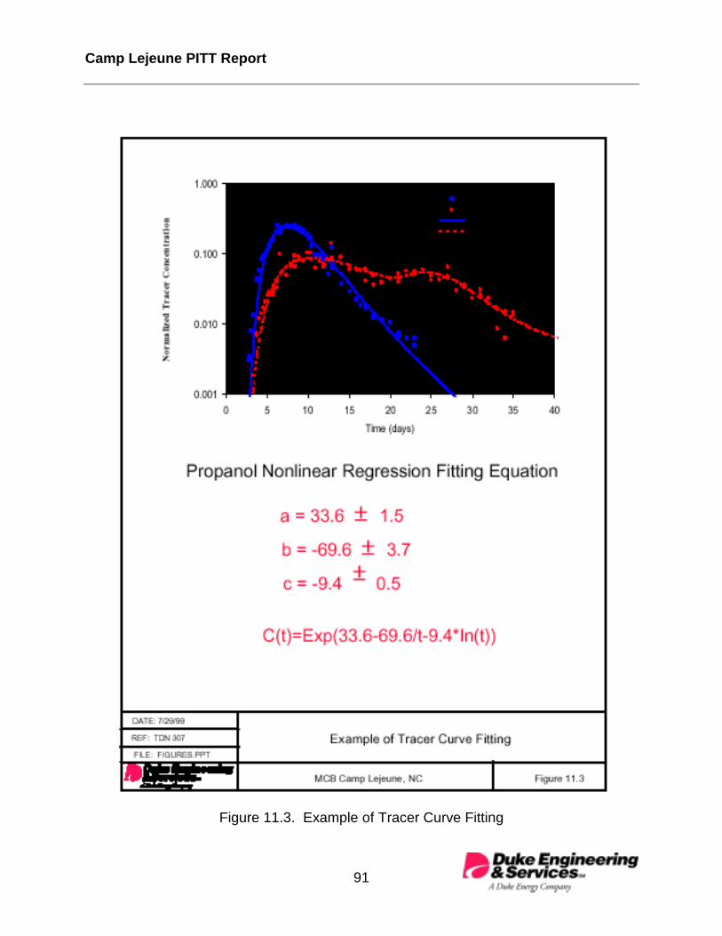
Camp Lejeune PITT Report
91
Figure 11.3. Example of Tracer Curve Fitting

Camp Lejeune PITT Report
92
2)(
)(
0
0 s
p
pp
t
dttC
dtttCt
f
f
t
t
−= , (11.1-3)
and
2)(
)(
0
0 s
n
nn
t
dttC
dtttCt
f
f
t
t
−= , (11.1-4)
where st is the slug size, i.e., the time period in which the tracer mass was injectedduring tracer test, ft is the tracer test cutoff time, and )(tCp and )(tCn represent thepartitioning and nonpartitioning tracer concentration as a function of time, respectively.
The average DNAPL saturation was estimated by calculating the first moments of thepartitioning and nonpartitioning tracers using equations (11.1-3) and (11.1-4), bynumerically integrating the corresponding tracer response curves. Next, equation(11.1-2) was used to calculate the retardation factor and then equation (11.1-1) wasused to estimate the average DNAPL saturation in the swept volume.
With nS and nt known, the tracer swept pore volume of one particular extraction well( pV ) is now calculated as,
n
np S
tQMmV
−=
1(11.1-5)
where M is the total mass of tracer injected, and m is the total mass of tracer producedfrom the particular extraction well. Q is the total injection rate.
For the conservative tracer test, the tracer only sweeps the pore volume occupied bywater. The tracer swept pore volume of the one particular extraction well in this casecan be calculated as,
MtmQV n
p = (11.1-6)

Camp Lejeune PITT Report
93
11.4 PITT Data Analysis
11.4.1 Extraction Well Tracer Data Analysis
Tracer concentrations for PITT samples were normalized to tracer injectateconcentrations. Normalized concentrations, which are dimensionless, are calculated bydividing each measured sample concentration by the averaged tracer injectateconcentration (also measured by GC analysis). The normalized tracer concentrationhistories and the corresponding fitted curves for the six extraction wells are shown inFigures 11.4a through 11.9. In each of the figures presented, the top graph shows thetracer concentration in a linear scale and the bottom in a semi-log scale. The linearscale graphs show the separation of tracer peak concentrations better while the semi-log scales give more information on the tailing of tracer response curves.
The data for only one conservative tracer (1-propanol) and two partitioning tracers(1-hexanol and 1-heptanol) data are presented in these figures. This is because thepartition coefficient of 4M2P is very small, and negligible chromatographic separationwas observed in this PITT between 4M2P and the conservative tracer. The separationof the tracer response between 1-propanol and 1-heptanol in all six extraction wellsclearly indicates the presence of DNAPL in the pore space swept by the partitioningtracers. Since the degree of separation is different for each well, it can be inferred thatthe DNAPL is not uniformly distributed in the pore space swept by the partitioningtracers. Since the degree of tracer separation decreases for the wells farther awayfrom the building, this also implies that most of the DNAPL in the test zone is near thebuilding.
The tracer curves were analyzed using the method of first temporal moment aspresented in Section 11.1 of this report. The resulting estimates of the DNAPL volumewithin each interwell swept pore volume are summarized in Table 11.1. The porevolume (shown as swept volume) of the aquifer swept by the tracers, for each interwellpair, as determined by the moment analyses is also shown in this table. The totalaquifer pore volume swept by the tracers was 4,780 gallons as determined by summingthe swept volumes calculated for each interwell pair. Moment analysis of the tracerresponse curves gives an estimated volume of 87 gallons of DNAPL in this swept porevolume, corresponding to an average DNAPL saturation of 1.8% throughout the testzone. The cumulative tracer recovery for 1-propanol is 85%. The cumulative tracerrecovery for 1-propanol is 85%. The recoveries of the other tracers used areapproximately the same, in the range of 85% ± 3%.

Camp Lejeune PITT Report
94
Figure 11.4a. Extraction Well EX01: Hexanol Tracer Response

Camp Lejeune PITT Report
95
Figure 11.4b Extraction Well EX01: Heptanol Tracer Response

Camp Lejeune PITT Report
96
Figure 11.5 Extraction Well EX02: Heptanol Tracer Response

Camp Lejeune PITT Report
97
Figure 11.6 Extraction Well EX03: Heptanol Tracer Response

Camp Lejeune PITT Report
98
Figure 11.7a Extraction Well EX04R: Hexanol Tracer Response

Camp Lejeune PITT Report
99
Figure 11.7b Extraction Well EX04R: Heptanol Tracer Response

Camp Lejeune PITT Report
100
Figure 11.8. Extraction Well EX05: Heptanol Tracer Response

Camp Lejeune PITT Report
101
Figure 11.9. Extraction Well EX06: Heptanol Tracer Response

Camp Lejeune PITT Report
102
Table 11.1 Summary of Extraction Well PITT resultsWell Recovery
(%)Swept Volume
(gals)Saturation (%) PCE Volume (gals)
1-Hexanol 1-Heptanol 1-Hexanol 1-Heptanol 1-Hexanol 1-HeptanolEX01 13 790 790 4.1 3.9 33 31EX02 17 1030 0.5 5EX03 10 540 0.4 2
EX04R 14 790 790 3.7 4.5 29 36EX05 17 890 1.0 10EX06 14 740 0.4 3Total 85 4780 1.8 87
11.4.2 Multilevel Sampler Tracer Data Analysis
Tracer concentration histories for three multilevel sampling points MLS 2-17,MLS 3-17.5, and MLS 2-18.5 (ft bgs) are shown in Figure 11.10. Tracer data from thesix other multilevel sampling points was not available because these sampling pointswere incapable of yielding a sufficient flow to collect a viable sample, as discussed inSection 10.2.
The chromatographic separation of the partitioning tracer response at the three viableMLS sampling points confirms the existence of DNAPL at these depth locations. Basedon the observation and analysis of the partitioning tracer data, several conclusions weredrawn. First, the degree of tracer separation in monitor points MLS 2-17, MLS 3-17.5,and MLS 2-18.5 is observed to increase with depth, as shown in Figure 11.10. Basedon this observation, it is concluded that DNAPL saturation tends to increase with depthnear the base of the shallow aquifer, which implies that the majority of the DNAPL islocalized in the silty layer immediately above the clay aquitard. This coincides with soilsampling observations during the initial DNAPL zone investigations. Second, the MLSdata shows the non-partitioning tracer breakthrough and peak times are significantlylater in the basal silt layer compared to the overlying fine sands. From this it can beinferred that the hydraulic conductivity of the silty layer at the base of the shallowaquifer is lower by a factor of approximately 4 when compared to the overlying finesands. This has important implications for the SEAR design, as discussed inSection 12.
The MLS tracer data was analyzed by the same method as used for the extraction welltracer data, except that the MLS data analysis was limited to calculating DNAPLsaturation but not DNAPL volume. This is because the MLS sampling points aremonitor points along the tracer flow path between the injection and extraction wells, and

Camp Lejeune PITT Report
103
Figure 11.10. Multi-Level Sample Point Tracer Responses

Camp Lejeune PITT Report
104
there is no flow rate associated with the MLS sample points. The flow rate (Q) at anextraction well is required to calculate the swept pore volume, as shown inequation 11.1.5, which is then used to calculate DNAPL volume in the swept porevolume between a given pair of injection and extraction wells. It should also be notedthat the estimated value of DNAPL saturation at each MLS point does not represent theDNAPL saturation at the monitor point, but rather, it is the average DNAPL saturation inthe steamtube (tracer flowpath) from the injection well to the MLS monitor point. Basedon moment analysis of MLS tracer data for MLS-2 and MLS-3, it is estimated that theaverage DNAPL saturation is approximately 0.5% in the higher permeability layer(overlying fine sand), and about 3.6% in the lower permeability (basal silt) layer. It islikely that the DNAPL saturations are higher than this at locations closer to the building,however MLS-1 (located between IN01 and EX01; see Figure 4.1) was not functionalfor sampling, therefore there is no tracer data at this near-building MLS location.
The effective permeability contrast at the different MLS depths is represented by theratio of the first moments for the non-partitioning tracer response curves at the differentMLS monitor points. The results indicate that the effective permeability of the basal siltlayer is about four times lower than that of the overlying fine sands, and permeabilitymay be even lower near the basal contact of the shallow aquifer at the aquitard.However, no PITT samples were successfully collected from the lowest MLS samplingpoints, i.e., just above the aquitard, to confirm this possibility.
A summary of the DNAPL saturation estimates based on the MLS tracer data issummarized in Table 11.2. The results for effective permeability contrast estimation areshown in Table 11.3.
Table 11.2 Summary of Multilevel Sampler (MLS) Tracer Data Analysis ResultsMLS Saturation (%)
2-17.0 0.7*3-17.5 0.52-18.5 3.6
* High uncertainty due to the quality of the data.
Table 11.3 Estimated Effective Permeability Contrast
MLS Pair k Ratio
2-17.0 / 3-17.5 2
2-17.0 / 2-18.5 4
3-17.5 / 2-18.5 2

Camp Lejeune PITT Report
105
11.4.3 Comparison of PITT results to Simulation Predictions
The PITT data for the non-partitioning tracer, 1-propanol, is plotted against theUTCHEM simulation predictions for a non-partitioning tracer in Figures 11.11 to 11.13.These figures show excellent agreement between predicted and actual tracer response.However, tracer recoveries obtained during the PITT (85% ± 3%) were lower than theoriginal simulation prediction of 93% to 96%. As mentioned earlier, the water level andpumping rate data recorded continuously during the PITT show that hydraulic controlwas maintained throughout the PITT. A water level contour map produced using thisdata, provided as Figure 11.14, further supports this conclusion. As such, the lowerthan expected tracer recovery should not be due to loss of tracer out of thedemonstration area. The most likely explanation for the lower tracer recovery is that theanalyzed/reported tracer concentrations are lower than actual sample concentrations.The laboratory that analyzed the PITT samples experienced analytical problems asdiscussed in Sections 10.3 and 11.1, which may have contributed a low-levelsystematic underestimation of tracer concentrations for the PITT samples.
In addition to analytical difficulties, biodegradation of the tracers in the subsurface mayhave contributed to tracer loss to a minor degree. Biodegradation of the tracers mayhave been favored by the relatively high ground water temperature (due to the adjacentsteam vault) and noted organic content of the aquifer. While the impact of analyticalerrors and biodegradation is not easily quantified, they provide reasonable explanationsfor the deviation of actual tracer recoveries from the originally estimated value.Lessons learned from the GC analysis of PITT samples from this initial PITT at Site 88will be used to fine-tune the GC method for more accurate and reliable operations forthe final (post-SEAR) PITT.
11.5 Error Analysis
There are two main sources of errors associated with the analysis of partitioning tracerdata, which may contribute to uncertainty in the estimates of average DNAPLsaturation. The first source of error, ∆ Rf, is an uncertainty in the estimation of theretardation factor based on the actual tracer data for a pair of tracers (i.e., as a functionof scatter in the non-partitioning and partitioning tracer datasets). The second source oferror, ∆ Κ, is due to the uncertainty in the partition coefficient measurement. Based onthe theory of error propagation (Taylor, 1997; pg. 79), the error for DNAPL saturation,∆ SN, which accounts for the cumulative error from ∆ Rf and ∆ Κ, can be derived fromequation 11.1-1, as:
22
22 )
)1(1()
)1(( K
KRRR
KRKS
f
ff
fN ∆
−+−
+∆−+
=∆ (11.5-1)

Camp Lejeune PITT Report
106
Figure 11.11. Comparison of Non-partitioning Tracer Curves: UTCHEM Prediction vs.Actual PITT Data at Extraction Wells EX01 and EX02

Camp Lejeune PITT Report
107
Figure 11.12. Comparison of Non-partitioning Tracer Curves: UTCHEM Prediction vs.Actual PITT Data at Extraction Wells EX03 and EX04R

Camp Lejeune PITT Report
Figure 1Actual P
108
1.13. Comparison of Non-partitioning Tracer Curves: UTCHEM Prediction vs.ITT Data at Extraction Wells EX05 and EX06

Camp Lejeune PITT Report
109
Figure 11.14 Water Level Elevations During the PITT

Camp Lejeune PITT Report
110
The first source of error, ∆ Rf, can be estimated based on the standard error of thefitting parameters, as discussed in Section 11.2 of this report. A detailed discussion onestimating the standard error of the retardation factor from standard errors of the fittingparameters can be found in a recent paper by Jin and Pope (1998). Table 11.4summarizes the retardation factor estimated error of the retardation factor (Rf ± ∆ Rf)and the percent error of the retardation factor ( ∆ Rf/Rf) for 1-heptanol at each extractionwell.
The second source of error can be estimated based on error analyses of numerouslaboratory measurements of the tracer partition coefficient. It was found that theaverage relative error in the partition coefficient measurement, ∆ Κ, is expected to beabout 10% (G.A. Pope, University of Texas at Austin, personal communication, 1998).The laboratory measured partition coefficient of 1-heptanol is 35. This means that theuncertainty of the partition coefficient of 1-heptanol is 5.335 ± , which is a conservativeestimate for ∆ Κ given the % uncertainty in the lab measurements of Κ reported inTable 7.1.
Based upon these two sources of error, the uncertainty of saturation estimates usingequation 11.5-1 is summarized in Table 11.5.
Table 11.4 Uncertainty of DNAPL Saturation Estimates (1-propanol vs. 1-heptanol)
Well Rf ± ∆ Rf ∆ Rf/Rf (%) SN ± ∆ SN ∆ SN/SN (%)
EX01 2.45 ± 0.08 3.30 3.90 ± 0.44 11.2
EX02 1.16 ± 0.01 0.34 0.45 ± 0.05 11.5
EX03 1.13 ± 0.01 0.48 0.36 ± 0.04 10.7
EX04R 2.65 ± 0.37 14.0 4.50 ± 1.06 23.5
EX05 1.38 ± 0.02 1.10 1.07 ± 0.11 10.7
EX06 1.12 ± 0.01 0.88 0.35 ± 0.05 12.9
Note: Κ ± ∆ Κ = 35 ± 3.5 for 1-heptanol; and ∆ Κ/Κ (%) = 10
As Table 11.4 indicates, the relative error of the retardation factor ( ∆ Rf/Rf) is generallysmall (<~3%) compared to the relative error of the tracer partition coefficient estimation,i.e., 10%. The only exception in this case is EX04R where the relative error of theretardation factor is somewhat higher due to the scattering of the GC tracer data.
In general, the uncertainty of DNAPL saturation estimation is inversely proportional tothe tracer partition coefficient as shown in equation 11.5-1. Tracers with higher partitioncoefficients will lead to larger retardation factors and improved accuracy in DNAPL

Camp Lejeune PITT Report
111
volume estimation. This has also been illustrated on a theoretical basis by Jin (1995).In practice, the retardation factor has to be at least 1.2 in order to have a reliableDNAPL volume and saturation estimate. If the tracers with large partition coefficients,such as 1-heptanol, still yield retardation factors in the range of 1.0 to 1.1, it means thatthere is little, if any, DNAPL present in the subsurface being tested.
The above analysis of potential DNAPL saturation estimation error does not account forerrors which may be due to uneven distribution of Varsol across the site (i.e., Varsolthat is dissolved in the PCE DNAPL). Recently collected (free-phase) DNAPL samplesindicate that at extraction wells EX01 and EX04, Varsol concentrations may be ashigh as 4-14 wt% of the DNAPL. Previously, Varsol concentrations had not beenobserved to exceed 2 wt%. Based on the Equivalent Alkane Carbon Number (EACN)approach (Dwarakanath and Pope, 1998), it is possible to estimate the influence ofVarsol on the estimated DNAPL saturation. Using this approach, with 4-14 wt%Varsol present in the DNAPL, the underestimate in DNAPL saturations by PITT dataanalysis would be between 2-5% (see Appendix Q), which is relatively negligible.
A final source of estimation error is from the extrapolation of experimental data.Extrapolation of experimental data is required when the tails of the tracer concentrationhistories are not fully characterized due to limitations in the GC detection limits. Thiscan cause under prediction of the average DNAPL saturation and hence causeestimation errors. These errors would be large or small depending on the quality of thetracer data. The data extrapolation technique is very simple and sound in its principle.However if there is significant scattering in the tracer concentration tail due to the effectof analysis errors and low tracer concentrations (on the order of the detection limit), agreat deal of engineering judgment and subjectivity may be required to pick the correctexponential decline of the tracer tail. The average DNAPL saturations are highlysensitive to the changes in the slope of the exponential decline curve and this cancause a relatively large uncertainty in the average DNAPL saturation estimates. On theother hand, if the tracer data is of good quality and a linear decline in tracerconcentrations on a semi-log plot is observed, the extrapolation errors will be minimal.If extrapolation errors are minimal, the result will be a significant increase in the overallestimation accuracy of the average DNAPL saturations. The tracer data showsreasonably linear declines in tracer concentrations on the semi-log plots for data abovethe detection limit (Figures 11.4a to11.9), and it is our professional judgement that anyerror associated with extrapolation of the data is not significant with respect to theresulting estimates for DNAPL saturation.
The above error discussion is based on the assumption that all observed tracerretardation is due to tracer partitioning to DNAPL. However, the column testexperiments, discussed in Section 7, have shown that the elevated sedimentary organiccontent, as a result of peat particles in the sediments, can lead to tracer sorption to thenatural organic matter which gives an apparent response for the presence of DNAPL inuncontaminated sediments. Pre-PITT soil sampling indicated that little or no DNAPL is

Camp Lejeune PITT Report
112
likely present in the zone between EX03 and EX06 (see Figure 3.3). The tracerresponse at EX03 and EX06, which lead to a combined estimate of approximately 5gallons of DNAPL for these two interwell locations, may actually be due to tracerinterference with the sedimentary organic carbon, i.e., peat, in the sediments.Furthermore, it is likely that of the DNAPL measured by the PITT at EX02 and EX05(0.5% and 1.0% saturations, respectively), a significant portion of the tracer retardationwas due to tracer sorption to the peat. It is not, however, believed that the peat playedany significant role in the tracer response at wells EX01 and EX04R, where DNAPLsaturations were measured to be 3.9 and 4.5%, respectively.
11.6 Summary and Conclusions of PITT Results
Moment analysis of the PITT data estimated a DNAPL volume of 87 gallons in theswept volume of about 4,800 gallons. The DNAPL is non-uniformly distributed in thegeosystem and the majority of the DNAPL is localized in the basal silt layer overlyingthe aquitard. There is a tendency for the DNAPL saturation to increase with depth anddecrease laterally away from the building. The measured average DNAPL saturationfor the well pairs near the building is about 4.5%, and 0.4% for the well pairs away fromthe building.
However, it should be noted that although the results from the PITT are reliable, theDNAPL volume estimation of 87 gallons is not exact. There are several factors thatcould contribute to an overestimate or underestimate of DNAPL in the test zone. Thepresence of peat particles in DNAPL-zone sediments, which elevates the sedimentaryorganic carbon content in the sediments, has been shown in column tests to interferewith tracer retardation such that DNAPL appears to be present in uncontaminatedsediments at low-level DNAPL saturations of approximately 0.3% to 0.5%. Unless thisis accounted for, it may lead to overestimation of the volume of DNAPL in the test zone.It is believed that this interference is responsible for an apparent volume ofapproximately 13 gallons of DNAPL in the swept pore zones represented by samplescollected from extraction wells EX02, EX03, EX05, and EX06. Therefore, the correctedestimate for the total volume of DNAPL measured by the PITT is 74 gallons. Thiscorrection is based upon the results of soil column tests which showed an apparentDNAPL saturation of 0.3 to 0.5% in uncontaminated soil. It is possible that the actualvolume of DNAPL is even somewhat lower than 74 gallons since the degree of tracersorption to natural organic matter is a function of the degree of the foc present inuncontaminated and/or in low-level DNAPL-contaminated portions of the test zone.The column experiments were conducted with fine sand sediments with foc values thatranged from 1200 to 2100 mg/kg (Section 7.4.1). However, foc analyses conducted onthree soil samples collected from the basal, fining downward sediments in the DNAPLzone (grading from fine sand to clayey silt just above the aquitard contact) resulted in focvalues that range from 1500 to 6400 mg/kg (Table 3.2).

Camp Lejeune PITT Report
113
Conversely, factors that may have contributed to an underestimate of DNAPL include:(1) the presence and production of free-phase DNAPL during the PITT; (2) slightlylower tracer recovery by chemical analysis after the holding time had expired; and (3)the higher than anticipated Varsol concentrations in the DNAPL. These factors havenot been quantified in the error analysis, as presented in the above section. Takingthese factors into account, it is estimated that an additional 14 gallons of DNAPL maybe present in the test zone for a total of about 88 gallons.

Camp Lejeune PITT Report
114
12.0 SUMMARY AND CONCLUSIONS
Duke Engineering & Services completed characterization of a PCE DNAPL zone at Site88, US Marine Corps Base, Camp Lejeune, NC, in cooperation with BakerEnvironmental during 1997 and the first half of 1998. The Site 88 DNAPL zone waslocated at 17 to 20 ft bgs, both beneath and adjacent to Building 25, the Base dry-cleaning facility. In addition to the DNAPL zone, a zone of LNAPL has also beenidentified at a depth of approximately 7 to 10 ft bgs. This LNAPL zone is contaminatedwith Varsol , a petroleum distillate that was used as the dry-cleaning solvent before itwas replaced by PCE in the 1970s.
The shallow aquifer containing the PCE DNAPL zone is composed of fine sand and siltwith an average hydraulic conductivity of approximately 5 x 10⁻⁴ cm/s (~1.4 ft/day). Thesediments grade finer at the base of the aquifer to a clayey silt immediately above theclay aquitard; this basal silt layer was measured to have a hydraulic conductivity ofabout 1 x 10⁻⁴ cm/s (~0.3 ft/day). The clay aquitard, at the base of the shallow aquifer,appears to provide effective protection against further downward migration of DNAPLcontamination to the underlying Castle Hayne Aquifer. The equivalent pressure forentry of DNAPL into the clay aquitard was measured to be approximately 15 ft ofDNAPL head. The hydraulic head drop across the aquitard from the shallow aquifer tothe Upper Portion of the Castle Hayne is of the order of 7 ft.
The DNAPL zone extends laterally in the shallow sand aquifer to approximately 20 to30 ft north of Building 25 and is bounded below by the clay aquitard. The upper surfaceof the clay layer forms a stratigraphic trap (i.e., depression) in which some of theDNAPL has pooled. DNAPL saturations increase with depth from 17 to 20 ft bgs, withresidual DNAPL grading downward to free-phase DNAPL above the clay surface. Thisfree-phase DNAPL is, however, contained within clayey silts and the ability to recoverDNAPL from this zone via traditional pumping from recovery wells is very limited.
A well field of three injection, six extraction, and two hydraulic control wells was installedfor use in a partitioning interwell tracer test, or PITT, to measure the volume and spatialdistribution of PCE DNAPL in the test zone. During the PITT, the tracers swept a porevolume of approximately 4,800 gallons of the shallow aquifer, in the depth intervalbetween about 15 to 20 ft bgs. A UTCHEM-based geosystem model of the well fieldwas developed for preliminary design of the PITT. The geosystem model was updatedand calibrated based on the results of a conservative interwell tracer test (usingbromide as a tracer). The updated/calibrated model was then used for furthersimulations to finalize the PITT design.
It was determined by partitioning tracer testing over a period of forty days in May-June1998 that the DNAPL zone contained approximately 74-88 gallons of PCE DNAPL.Additional DNAPL is known to be present directly beneath Building 25, but that area

Camp Lejeune PITT Report
115
was not included in this DNAPL investigation because of potential operational conflictswith ongoing dry-cleaning activities. The average DNAPL saturations measured by thePITT ranged from approximately 4.5% adjacent to Building 25 and decreasing to 0.4%at a distance of 20 ft away from Building 25. It appears likely, however, that the low-level DNAPL contamination detected by the PITT in the test zone area away from thebuilding (i.e., 0.4% DNAPL saturation) is actually the result of tracer sorption to naturalorganic matter (i.e. peat) in the sediments rather than partitioning to DNAPL. Thisconclusion is supported by column test results that were obtained prior to the PITT.Therefore, the area approximately 20 ft north of the building appears likely to beDNAPL free. The results of the SEAR demonstration will provide clarification for thepresence or absence of DNAPL in this area of the test zone. Finally, the PITT datarevealed an approximately four-fold decrease in effective permeability between the finesands and basal silt zones in the test zone portion of shallow aquifer.
These results have several implications for the SEAR demonstration. Firstly, it showsthat the geosystem model developed thus far is a reasonable representation of thecontaminated DNAPL zone in the test area; corrections to accommodate potentialbiodegradation of injected chemicals as well as varying Varsol concentrations acrossthe test zone will improve the model. Secondly, it illustrates that most of the PCEDNAPL is in the lower permeability (basal) zone of the aquifer, and that the remediationchallenge will be to design the surfactant flood to effectively remove the DNAPLcontamination from this zone. Finally, it indicates that there is some utility to including anon-alcohol based conservative tracer (e.g. bromide) in the tracer suite to examine thepotential biodegradation of alcohol tracers during the final post-SEAR PITT.
Analytical difficulties were encountered during this PITT that point to the need toaddress GC fouling by calcium chloride in order to obtain an accurate analysis of theSEAR and post-SEAR PITT samples.
Finally, the pre-SEAR PITT has provided valuable data for evaluating the baselineconditions within the test zone for SEAR test design. The data on the averaged DNAPLsaturations, the DNAPL volume in the test zone, and the approximate DNAPLdistribution will refine the existing site geosystem model for optimum SEAR design.

Camp Lejeune PITT Report
116
13.0 REFERENCES
Annable M.D., P.S.C. Rao, K. Hatfield., W.D. Graham., A.L. Wood and C.G. Enfield,1998. Partitioning Tracers for Measuring Residual NAPL: Field Scale TestResults. J Env. Eng., June, 1998, pp.498-503.
Baker Environmental. 1996. “Phase I Investigation Report, Operable Unit No. 15 (Site88), Marine Corps Base Camp Lejeune, North Carolina”; prepared for the NavalFacilities Engineering Command, Atlantic Division (LANTDIV).
Baker, 1997. Dense Nonaqueous Phase Liquid Investigation Summary Report,Operable Unit No. 15 (Site 88), Marine Corps Base MCB Camp Lejeune, NorthCarolina. Report prepared for the Dept of the Navy Atlantic Division, NavalFacilities Engineering Command, Norfolk, Virginia, September 15, 1997.
Baker, 1998a. Focused Remedial Investigation Report, Operable Unit No. 15 (Site 88),Marine Corps Base Camp Lejeune, North Carolina. Report prepared for theDept of the Navy Atlantic Division, Naval Facilities Engineering Command,Norfolk, Virginia, May 15, 1997.
Baker, 1998b. Varsol Investigation Summary Report, Operable Unit No. 15 (Site 88),Marine Corps Base Camp Lejeune, North Carolina. Report prepared for theDept of the Navy Atlantic Division, Naval Facilities Engineering Command,Norfolk, Virginia, March 20, 1998.
Broholm K, and S. Feenstra, 1995. Laboratory Measurements of the AqueousSolubility of Mixtures of Chlorinated Solvents. Environ Toxicol Chem, (14)1, pp.9-15.
Caughey, M.E., M.J. Barcelona, R.M. Powell, R.A. Cahill, C. Gron, D. Lawrenz, andP.L. Meschi, 1995. Interlaboratory Study of a Method for DeterminingNonvolatile Organic Carbon in Aquifer Materials. Environmental Geology, v.26,pp. 211-219.
Cayais, J.L., R.S. Schechter and W.H. Wade, 1975. The Measurement of LowInterfacial Tension Via the Spinning Drop Technique. In: Adsorption atInterfaces, ACS Symposium series, 8, J.R. Gould (ed), American ChemicalSociety, Washington D.C., pp. 234.
Datta Gupta, A., G. A. Pope, and R. L. Thrasher, 1986. A Symmetric, Positive DefiniteFormulation of a Three-Dimensional Micellar/Polymer Simulator. SPE Reser.Eng., 1(6), p622.

Camp Lejeune PITT Report
117
Delshad, M., G.A. Pope, and K. Sepehrnoori, 1996. A Compositional Simulator forModeling Surfactant-Enhanced Aquifer Remediation: 1. Formulation. J.Contaminant Hydrology, v23, pp. 303-327.
Demond, A.H. and A.S. Lindner, 1993. Estimation of Interfacial Tension BetweenOrganic Liquids and Water. Environmental Science & Technology, (27)12, pp.2318-2331.
DE&S, 1998. Demonstration of Surfactant-Enhanced Aquifer Remediation ofChlorinated Solvent DNAPL at Operable Unit 2, Hill AFB, Utah. Prepared for theAir Force Center for Environmental Excellence Technology Transfer Division,Brooks Air Force Base, Texas, and OO-ALC/EMR, Hill Air Force Base, OgdenUtah, January 1998. Duke Engineering & Services, Austin, Texas.
DE&S, May 1998a. Work Plan for a Partitioning Interwell Tracer Test Site 88 MarineCorps Base Camp Lejeune, North Carolina. Duke Engineering & Services,Austin, Texas.
DE&S, May 1998b. Sampling and Analysis Plan for a Partitioning Interwell Tracer Test,Site 88 Marine Corps Base Camp Lejeune, North Carolina. Duke Engineering &Services, Austin, Texas.
Dwarakanath, V. and G.A. Pope, 1998. A New Approach for Estimating AlcoholPartition Coefficients between Nonaqueous Phase Liquids and Water.Environmental Science and Technology, 32(11) pp.1662-1666.
Edgar, J., 1997. MS Thesis, The University of Texas at Austin.
Environmental Protection Agency, 1992. Estimating Potential for Occurrence of DNAPLat Superfund Sites. Publication 9355.4-07FS, Office of Solid Waste andEmergency Response (OSWER), Washington D.C. January 1992.
Freeze, R.A., and J.A. Cherry, 1979. Groundwater, Prentice-Hall, Englewood Cliffs, NJ,604 pp.
INTERA, 1997. Demonstration of Surfactant-Enhanced Aquifer Remediation ofChlorinated Solvent DNAPL At Operable Unit 2, Hill AFB, Utah. Prepared for theAir Force Center for Environmental Excellence, Technology Transfer Division,Brooks Air Force Base, San Antonio, Texas, Draft. Duke Engineering & Services(formerly INTERA), Austin, Texas.
Jin, M., M. Delshad, V. Dwarakanath, D.C. McKinney, G.A. Pope, K. Sepehrnoori, C.E.Tilford, and R.E. Jackson, 1995. Partitioning Tracer Test for Detection,Estimation and Remediation Performance Assessment of SubsurfaceNonaqueous Phase Liquids. Water Resources Research, (31)5, pp. 1201-1211.

Camp Lejeune PITT Report
118
Jin, M., 1995. Surfactant-Enhanced Remediation and Interwell Partitioning Tracer Testfor Characterization of NAPL Contaminated Aquifers. Ph.D. Dissertation,University of Texas at Austin.
Jin, M., Jackson, R.E., Pope, G.A., and S. Taffinder, 1997. Development of PartitioningTracer Tests for Characterization of Nonaqueous-Phase Liquid-ContaminatedAquifers. SPE 39293. Presented at the SPE 72nd Annual Technical Conference& Exhibition held in San Antonio, Texas, 5-8 October 1997.
Jin, M., Butler, G.W., Jackson, R.E., Mariner, P.E., Pickens, J.F., Pope, G.A., Brown,C.L., and D.C. McKinney, 1997b. Sensitivity Models and Design Protocol forPartitioning Tracer Tests in Alluvial Aquifers. Ground Water, v.35, no.6, pp 964-972.
Jin, M. and G. Pope, 1998. The Interpretation and Error Analysis of PartitioningInterwell Tracer Test Data. submitted for publication to Environmental Science &Technology
Mackay, D.M. and J.A. Cherry, 1989. Groundwater Contamination: Pump-and-TreatRemediation. Environmental Science & Technology, v.23, no.6, pp.630-636.
Mariner, P.E., M. Jin, and R.E. Jackson, 1997. An Algorithm for the Estimation ofNAPL Saturation and Composition from Typical Soil Chemical Analyses.Ground-Water Monitoring and Remediation, v.17, no. 2, pp. 122-129.
Neuman, S.P., 1975. Analysis of Pumping Test Data from Anisotropic UnconfinedAquifers Considering Delayed Yield. Water Resources Research, vol. 11, no. 2,pp. 329-342.
Pope, G.A. and R.C. Nelson, 1978. A Chemical Flooding Compositional Simulator.SPE J. 18(5), p339.
Pope, G.A., M. Jin, V. Dwarakanath, B. Rouse, and K. Sepehrnoori, 1994. PartitioningTracer Tests to Characterize Organic Contaminants. In: Proceedings of the 2nd
Tracer Workshop, University of Texas at Austin, November 14th & 15th, 1994.
Pope, G.A. and W.H. Wade, 1995. Lessons from enhanced oil recovery research forsurfactant enhanced aquifer remediation. In: Sabatini, D.A., Knox, R.C.,Harwell, J.H. (Eds.), Surfactant-Enhanced Subsurface Remediation EmergingTechnologies, ACS symposium series 594, American Chemical Society,Washington, DC, 142-160.

Camp Lejeune PITT Report
119
Rice University, INTERA, University of Texas at Austin, and Radian, 1997.Surfactant/Foam Process for Aquifer Remediation – Draft Final. Prepared forthe Advanced Applied Technology Demonstration Facility, Rice University,Houston, Texas. November.
Saad, N., G.A. Pope, and K. Sepehrnoori, 1990. Application of Higher-Order Methodsin Compositional Simulation. SPE Reser. Eng. 5(4), p623.
Schwarzenbach, R.P and J. Westall, 1981. Transport of Nonpolar Organic Compoundsfrom Surface Water to Groundwater; Laboratory Sorption Studies. EnvironmentalScience and Technology, v.15, p.1360.
Taylor, J.R., 1997. An Introduction to Error Analysis, second edition, University ScienceBooks, Sausalito, Calif.
West C.C., 1992. Surfactant-Enhanced Solubilization of Tetrachloroethylene andDegradation Products in Pump and Treat Remediation. In: Transport andRemediation of Subsurface Contaminants, edited by Sabatini, D. and R.C. Knox,ACS Symp Series 491, ACS Washington DC, pp. 149-158).
Young, C.M., R.E. Jackson, M. Jin, J.T. Londergan, P.E. Mariner, G.A. Pope, F.J.Anderson, and T. Houk, 1999. Characterization of a TCE DNAPL Zone inAlluvium by Partitioning Tracers. Accepted for publication by Ground WaterMonitoring and Remediation, Winter Issue, v. XIX, no. 1, pp 84-94.