djokic terrain processing for efficient 1d and 2d h&h modeling · feature class drainage line...
TRANSCRIPT
Terrain Processing for Efficient 1D and 2D H&H Modeling
Dean Djokic and Zichuan Ye, Esri Inc.

Overview
• Overview of GIS for H&H modeling support (why do we do this)• Terrain processing techniques• 1D vs. 2D modeling with GIS • GIS techniques for data simplification
• Schematization• “Lumping”/characterization• “Weeding”/VIP identification
• 2D (terrain)• 1D
• Discussion

GIS for H&H modeling support

Model and Data Integration !?• Integration of data, data models, and analyses in a functional system used to support decision process (spatial decision support system)
GIS
Local HMS
RAS
ICPR
EPA
USGS
Other …Other …
Data Providers Models

Types of Model Integration – Linked(most commonly used approach)
• GIS is linked to external models• GIS internal tools preprocess and post‐process model data for cost‐efficient and visually effective results
• GIS and models maintain their distinctive user interfaces
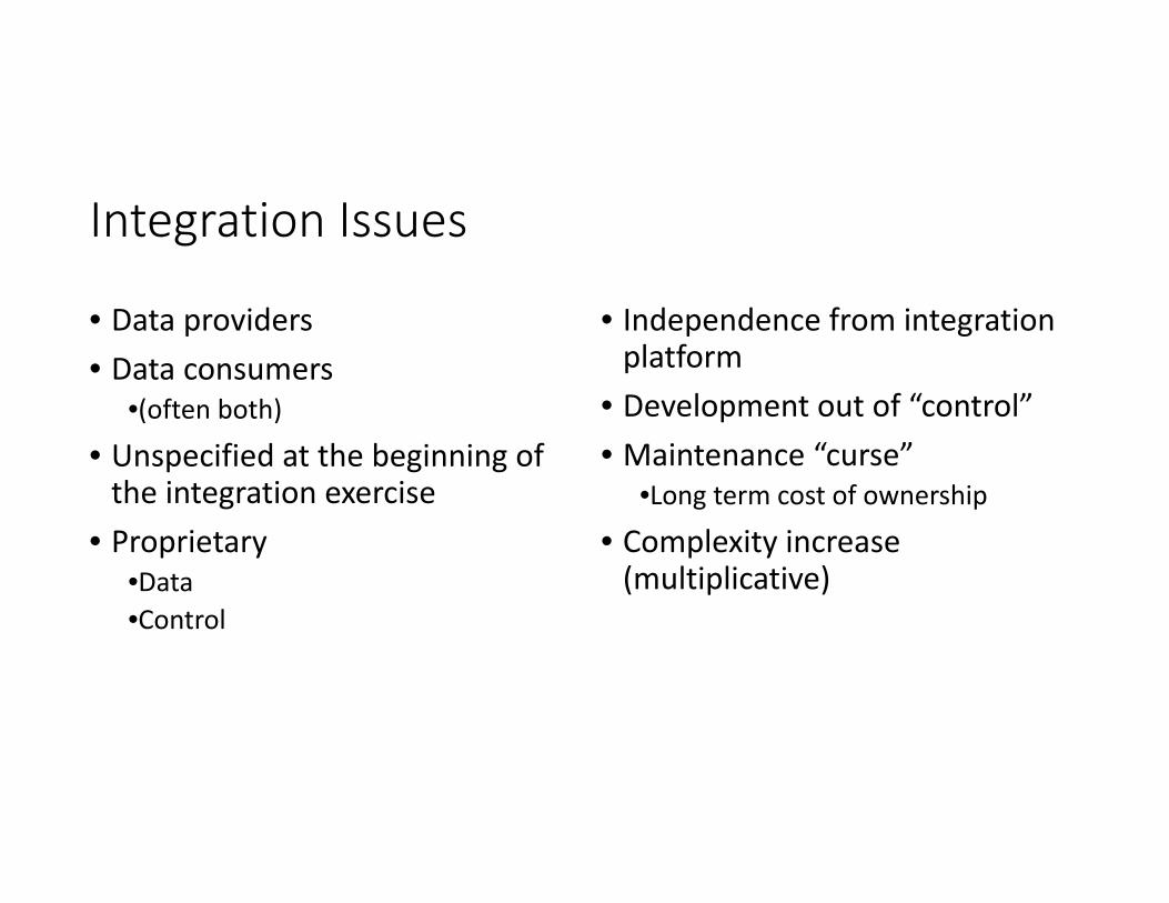
Integration Issues
• Data providers• Data consumers
•(often both)• Unspecified at the beginning of the integration exercise
• Proprietary•Data•Control
• Independence from integration platform
• Development out of “control”• Maintenance “curse”
•Long term cost of ownership
• Complexity increase (multiplicative)

Integration Issues (direct interfacing)
GIS
MIKE 21 HMS
FLDWAV
SWMM
MIKE 11
RAS
Other …
N
N * (N - 1)Bi-directional

GIS
MIKE 21 HMS
FLDWAV
SWMM
MIKE 11
RAS
Other …
N
2 * NBi-directional
XML
Integration Issues (intermediary interfacing)
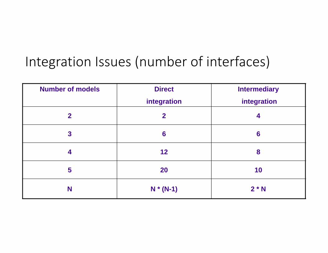
Integration Issues (number of interfaces)
Number of models Direct
integration
Intermediary
integration
2 2 4
3 6 6
4 12 8
5 20 10
N N * (N-1) 2 * N

Model Integration Approach
• Whatever works for particular situation – different conditions even for the same integration “problem” can result in a different integration method
• Tight or loose coupling• Technical issues• Legal issues
• Access to the underlying model structure or not (NSS vs. Excel)
• Check out the existence of 3rd party solutions• Almost always cheaper to buy a solution than to develop one except for simple tasks.

Data Exchange Methods
• GIS is a “database” – any application that can read and write into one of supported databases has already an interface to GIS data (feature attributes).
• No direct access to geometry, projection parameters, …• Use RDBMS native development tools (VBA, ORACLE Forms, …)
• Custom ArcObjects code – full access to every element of ArcGIS in COM environment
• Allows tight coupling of GIS and numerical models• Using other software that can read/write to the same structures as the “meeting” ground (e.g. Excel, shape files)
• Data exchange tools/extension built into Arc Hydro (XML route)

Terrain processing techniques

Terrain Preprocessing
• Building an interconnected set of spatial data:• Raster data:
• DEM, flow direction, flow accumulation, drainage lines, sinks, …• Vector data:
• Drainage lines, catchments, adjoint catchments, sinks, lakes, …
• Different types of terrain morphologies and related tools:• Dendritic (no internal drainage areas)• Deranged (sinks)• Combined

Terrain Processing Workflows, Workflows, Workflows (1)
Fill sinks
DEMgrid
HydroDEM (1)grid
Flow direction
Flow directiongrid
Flow accumulation
Flow accumulationgrid
Stream definition
Streamgrid
Stream segmentation
Stream linkgrid
1
Start 1
Catchment grid delineation
Catchmentgrid
Catchment polygon
processing
Catchmentfeature class
Drainage line processing
Drainage linefeature class
Adjoint catchment processing
Adjoint catchmentfeature class
End
Grid datasset
Feature class dataset
Function
LegendFill sinks
DEMgrid
HydroDEM (1)grid
Flow direction
Flow directiongrid
Continue dendritic processing with flow
accumulation function
Start
DEM Reconditioning
HydroDEM (2)grid
Riverfeature class
Fill sinks (2)
HydroDEM (3)grid
Grid datasset
Feature class dataset
Function
Legend
Optional Function
• Burning streams
Continue dendritic processing with flow
accumulation function
Alte
rnat
ive
Pro
cess
ing
Fill sinks
DEMgrid
HydroDEM (1)grid
Adjust flow direction in lakes
Flow directionGrid (2)
Start
DEM Reconditioning
HydroDEM (2)grid
Riverfeature class
Fill sinks (2)
HydroDEM (3)grid
Flow direction
Flow directiongrid
Grid datasset
Feature class dataset
Function
Legend
Optional Function
• Bowling lakes
• Fencing
Continue dendritic processing with flow
accumulation function
Alte
rnat
ive
Pro
cess
ing
Fill sinks
DEMgrid
HydroDEM (1)grid
Adjust flow direction in lakes
Flow directionGrid (2)
Start
DEM Reconditioning
HydroDEM (2)grid
Riverfeature class
Fill sinks (2)
HydroDEM (3)grid
Flow direction
Flow directiongrid
Build walls
HydroDEM (4)grid
Outer wallfeature class
Inner wallfeature class
Grid datasset
Feature class dataset
Function
Legend
Optional Function
14
“Basic” dendritic preprocessing

Terrain Processing Workflows (2)
• Additional tools and workflows for deranged and combined morphologies
15
Deranged Combined Dendritic
Function \ Use Case UC1 UC2 UC3 UC4 UC5 UC6 UC7 UC8 UC9
Sink Evaluation X X X
Create Sink Structures X X X X X X
Flow Direction X X X X X X X X X
Adjust Flow Direction in Sinks X X X X X X
Sink Watershed Delineation X X X X X X
Append Coastal Catchments X X X X X X X X X
Assign CatType Attribute to Catchment FC
X X X X X X X X X
Fill Sinks X X X X X X X X
Level DEM X X X
Flow Accumulation X X X X
Stream Definition X X X X
Stream Segmentation X X X X
Combine Stream Link and Sink Link X X X
Drainage Line Processing X X X X
Adjust Flow Direction in Lakes X X X
Catchment Grid Delineation X X X X X X
Catchment Polygon Processing X X X X X X
Adjoint Catchment Processing X X X X X X
Create Drainage Line Structures X X X
DEM Reconditioning X X X X
Adjust Flow Direction in Streams X X X

Terrain Processing Workflows (3)
• Capture in model builder models (but beware of the “super buttons”)
16

Watershed Delineation (1)
• Arc Hydro watershed delineation functions leverage preprocessed data.
• Interactive local and global watershed delineation• Batch local and global watershed delineation• Batch subwatershed delineation
• Characterization functions leverage preprocessed data where possible.
• Preprocessed data allow limitation of processing extent for raster processing thus speeding up the processing.
• “Analytical caching”

Watershed Delineation (2)
• Limit the extent of processing to the catchment the point is in to speed up the SA watershed function.
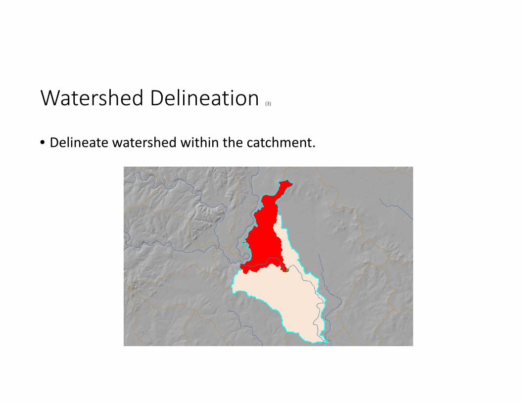
Watershed Delineation (3)
• Delineate watershed within the catchment.

Watershed Delineation (4)
• Append the local watershed with the adjoint catchment to get the full watershed to the point of interest.

Role of Threshold
• Controls the size of catchments.• Smaller catchments speed up local processing for watershed delineation and characterization (very important for responsiveness of the system). But there is operational overhead so reducing the catchment size has a limit with respect to performance gains.
• Smaller catchment slow down preprocessing and generate larger analytical dataset (but this is done only once and HD space is cheap).
• Quality control – does general flow pattern match expected patterns.• NOT to match some geomorphological expectations or some specific application requirements.

Global Delineation (1)
• Deal with scalability issues related to DEM size (large areas/high resolution)
• Approach• Combine raster analysis on individual areas (any size) that are manageable from DEM point of view, and network analysis between the individual areas
• Example – 10 HUC8 cataloging units

Global Delineation (2)
• Start with well defined database design structure
• Apply it independently to all DEM processing units
• HydroID does not have to be unique across GDBs
• Construct the extended network• Some work involved for HUC 8 processing units

• Define the point• Delineate local watershed• Trace upstream• Identify contributing
catchements• Merge shapes and store
Global Delineation (3)

Global Delineation (4)
• Currently area and few topographic characteristics are computed –other parameters of interest are being added
• Aggregation types – additive, min, max, special
• Potentially interesting issues• Geometry size and complexity• Speed in aggregation (preprocessing option)

Practical Implementation (1)
• Global watershed delineation service• Global flow path tracing service• 90m SRTM‐based for the world• 30m NHDPlus V2‐based for the USA

Practical Implementation (2)
• Consume in desktop and/or web client
1D vs. 2D modeling with GIS
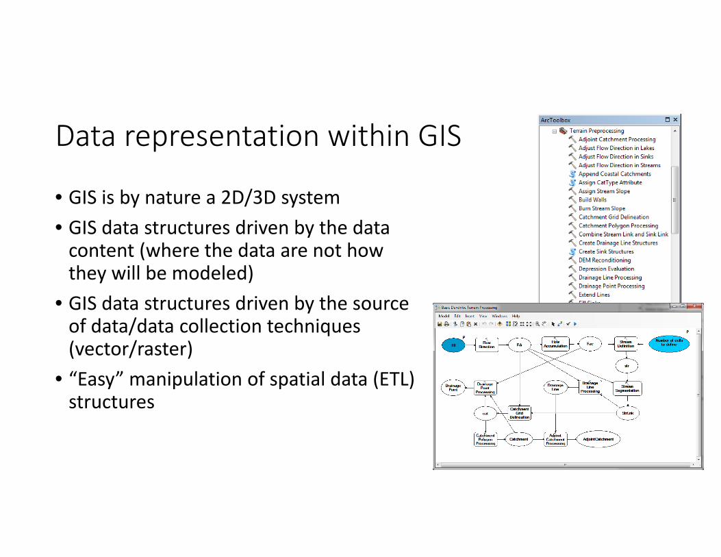
Data representation within GIS
• GIS is by nature a 2D/3D system• GIS data structures driven by the data content (where the data are not how they will be modeled)
• GIS data structures driven by the source of data/data collection techniques(vector/raster)
• “Easy” manipulation of spatial data (ETL) structures

Data representation within models
• Type of model defines its data structure (1D/2D/3D)• Model data structures driven by the solvers (how the data are modeled – e.g. FE/FD/FV)
• Not always easy (or often any) manipulation of spatial data structures
Typical GIS role in modeling support
• “Loose coupling” (GIS for model pre/post processing)• Space discretization• Space characterization• Data formatting• Visualization/results presentation

Typical GIS role in modeling support
Model type/function 1D 2D
Discretization Development of node-link or wireframe representation
“Development” of modeling schema (triangulation,
fishnet)
CharacterizationSpatial averaging/lumping
over discretized spatial elements
Spatial averaging/lumping over discretized spatial
elements and/or “push-pin” data extraction
Formatting Simpler data structures, smaller volumes
More complex data structures, larger volumes

GIS techniques for data simplification
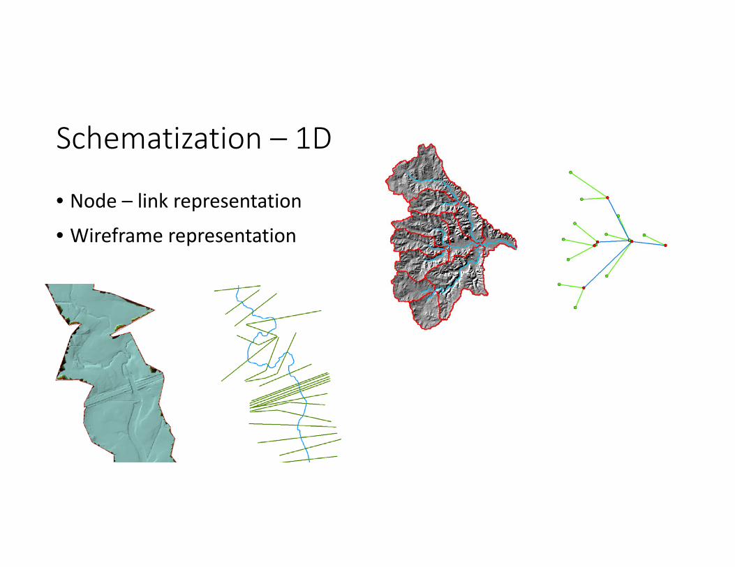
Schematization – 1D
• Node – link representation• Wireframe representation

Schematization – 2D
• Thiessen polygon
• TIN
• Fish net
• Can get tricky – need to understand solvers for optimal tessellation!
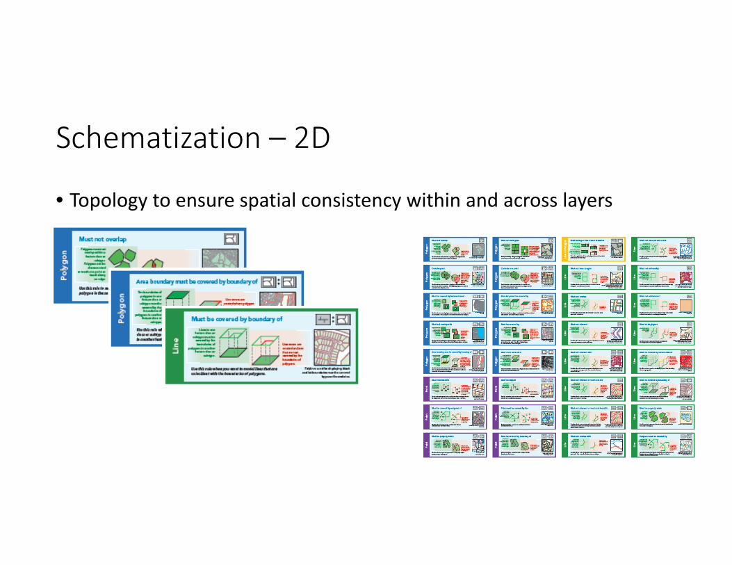
Schematization – 2D
• Topology to ensure spatial consistency within and across layers

“Lumping”/characterization
• Push‐pin (not much to do unless it needs “vertical” aggregation)• “Lumping”/characterization
• Zonal stats operations• Can do interpolation first, then stats

“Weeding”/VIP identification
• 2D (terrain/surface)• Terrain dataset (terrain pyramids)
• Window size• Z‐tolerance
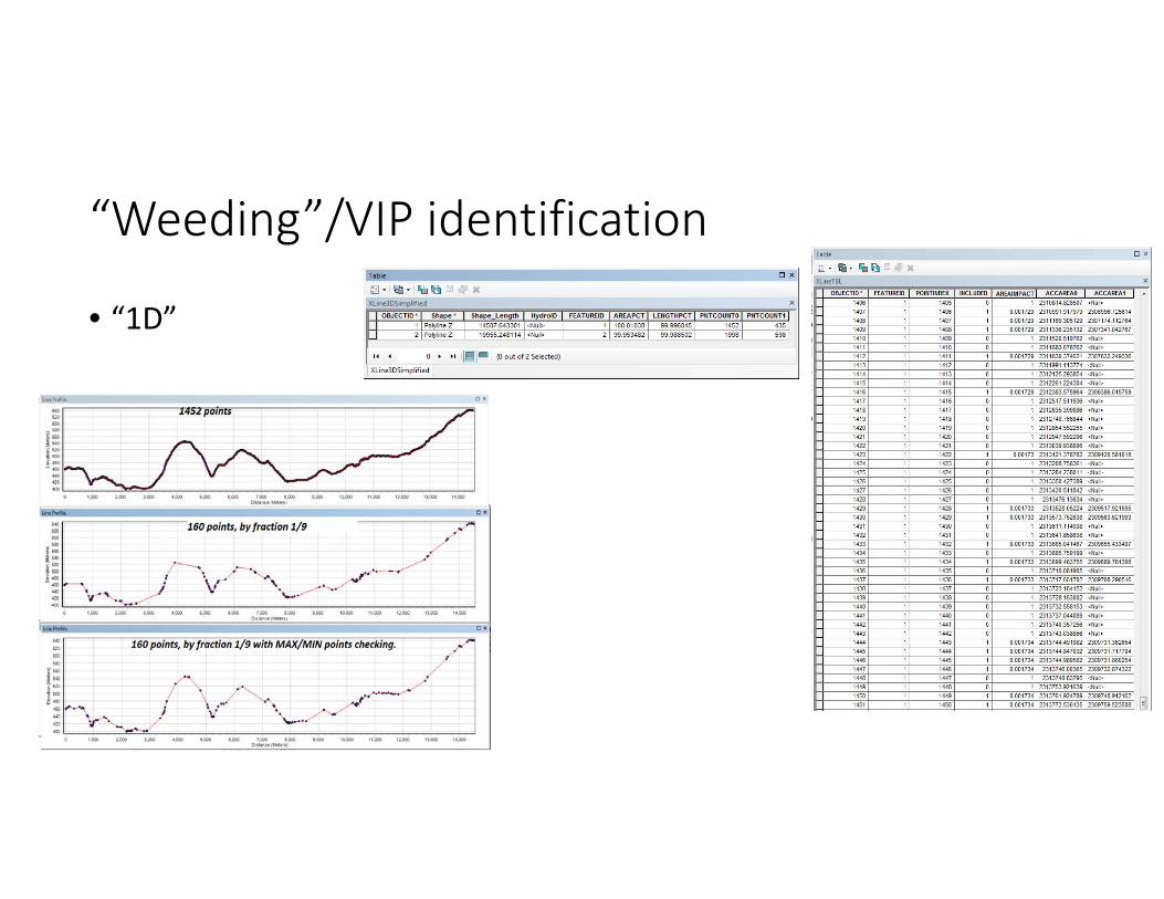
“Weeding”/VIP identification
• “1D”
Summary
• One terrain representation does not fit all• Understanding modeling techniques and their requirements on data preparation (model schematization in particular)
• Techniques for ensuring data consistency• Techniques for geometry simplification before going into 2D models

Questions / Discussion