division 200 – earthwork section 201 – clearing and
TRANSCRIPT
129
DIVISION 200 – EARTHWORK
SECTION 201 – CLEARING AND GRUBBING 201.01 Description This work shall consist of clearing, grubbing, removing, and disposing of all vegetation and debris within the construction limits shown on the plans, except such objects that are designated to remain or are to be removed in accordance with other sections of these specifications. If no construction limits are shown, the right-of-way and easement areas will be the construction limits. This work shall include the preservation from injury or defacement of all vegetation and objects designated to remain. Disposal of material shall be in accordance with 203.08. 10
CONSTRUCTION REQUIREMENTS 201.02 General Right-of-way lines and construction limits will be established. Trees, shrubs, plants, seeded or sodded shoulders, slopes or other items to remain will be designated. All such designated items and vegetation shall be preserved. All areas outside the construction limits shall remain in their original condition. All damage to natural terrain, vegetation, objects designated to remain, or areas outside the construction limits which have subsequently eroded or been damaged, shall be repaired or replaced 20 in accordance with 621.11. Tree wound dressing required for cut or scarred surfaces of trees or shrubs selected for retention shall be in accordance with 914.09(c). 201.03 Clearing and Grubbing Surface objects, trees, stumps, roots, and other protruding obstructions not designated to remain shall be cleared and grubbed, including mowing as required. Undisturbed sound stumps, roots, and non-perishable solid objects, which are a minimum of 3 ft below the final subgrade or slope of embankments, may be left, provided they are as nearly flush as possible. However, they shall not extend more than 4 in. above the ground line or low water level. Sound stumps may be cut off at 30 ground level outside the construction limits of cut and embankment areas if approved. Except in areas to be excavated, stump holes and other holes from which obstructions are removed shall be backfilled with suitable material and compacted in accordance with 203.23. Burning of perishable material shall be done in accordance with applicable laws, ordinances, rules, and regulations. All necessary permit approvals shall be obtained prior to burning. 40 Unless burned in accordance with the requirements herein, perishable materials and debris shall be removed from the right-of-way and disposed of in accordance with 203.08. If allowed, sod may be disposed of within the right-of-way.
201.03

130
All merchantable timber in the clearing area, which has not been removed from the right-of-way prior to the beginning of construction, shall become the property of the Contractor, unless otherwise provided. The value of the timber shall be taken into account when the bid is prepared. Low hanging branches and unsound or unsightly branches on trees or shrubs 50 designated to remain shall be removed as directed. Branches of trees extending over the roadbed shall be trimmed to give a clear height of 20 ft above the roadbed. All trimming shall be done by skilled workers and in accordance with good tree surgery practices. 201.04 Scalping Areas where excavations are to be made, or embankments are to be placed, shall be scalped to a maximum of 4 in. Scalping shall include the removal of material such as brush, roots, sod, grass, residue of agricultural crops, sawdust, and decayed vegetable matter from the surface of the ground. 60 201.05 Hedge Removal Hedges and shrubs shall be pulled or grubbed in such a manner as to ensure complete and permanent removal. 201.06 Method of Measurement When specified as a pay item, measurement of this work will be made by one or more of the following methods. (a) Area Basis 70 The work to be measured will be the number of acres and fractions thereof acceptably cleared and grubbed within the limits shown on the plans or staked for clearing and grubbing. Areas not shown on the plans or not staked for clearing and grubbing will not be measured for payment. (b) Lump Sum Basis If clearing and grubbing is specified as a lump sum pay item, no measurement of area will be made. (c) Individual Unit Basis 80 1. The diameter of trees will be measured at a height of 24 in.
above the ground. Trees of less than 4 in. in diameter will be classified as brush.
2. Stumps will be measured by determining the average diameter
at the cutoff location. 3. Scalping will be measured by the acre.
201.04

131
90 4. If the Schedule of Pay Items shows measurement to be on an
individual unit basis, the units will be designated and measured in accordance with the schedule of sizes as follows:
Measured Diameter at Height of 24 in. Pay Diameter 4 to 8 in. 6 in.
Over 8 to 12 in. 10 in. Over 12 to 24 in. 18 in. Over 24 to 36 in. 30 in. Over 36 to 60 in. 48 in.
Over 60 in. 60 in. 201.07 Basis of Payment The accepted quantities of clearing and grubbing will be paid for as specified and described below. Payment will be made under: 100 Pay Item Pay Unit Symbol Clearing and Grubbing .............................................................. ACRE ........................................................................ LS Clearing Right-of-Way .............................................................. LS Scalping ..................................................................................... ACRE ________, ________, Remove .................................................. EACH name size 110 (a) Area Basis The determined quantities will be paid for at the contract unit price per acre respectively for each of the pay items shown in the Schedule of Pay Items. (b) Lump Sum Basis If the Schedule of Pay Items shows a lump sum pay item, the lump sum price will be paid for all work shown within the construction limits. All clearing the Contractor is directed to perform outside the construction limits, including clearing for utility relocation which is for the benefit of the Department, and not simply for the Contractor’s convenience, will be paid for in accordance with 104.03 or 109.03 unless 120 such clearing is shown on the plans, in the Contract Information book, or is for the construction of fence or right-of-way markers. (c) Individual Unit Basis If individual unit quantities are shown in the Schedule of Pay Items, the accepted quantities will be paid for at the contract unit prices for the respective pay items.
201.07

132
Payment for tree removal sizes as designated in requirement 4 of 201.06(c), which are larger than those sizes shown as pay items, will be made on the basis of the largest size shown in the Schedule of Pay Items except as set out below. 130 (d) Clearing Right-of-Way If the Schedule of Pay Items contains a lump sum pay item for clearing right-of-way, such pay item shall include the cost of all work described in this section and all of the work performed in accordance with 202 within the construction limits except for such work set out specifically as pay items or as otherwise provided for herein. All clearing the Contractor is directed to perform outside the construction limits, including clearing for utility relocation which is for the benefit of the Department, and not simply for the Contractor’s convenience, will be paid for in accordance with 104.03 or 109.03 unless such clearing is shown on the plans, in the Contract Information book, or is for 140 the construction of fence or right-of-way markers. Except as specified in 621, the cost of repair or replacement of terrain, vegetation, objects designated to remain, or areas outside the construction limits which have been damaged by the Contractor or have subsequently eroded, shall be included in the cost of clearing right-of-way. (e) Exclusions If the Schedule of Pay Items does not contain an estimated quantity or a lump sum pay item for work described herein except as set out above, such work will not be paid 150 for directly. The cost thereof shall be included in the cost of other pay items.
SECTION 202 – REMOVAL OF STRUCTURES AND OBSTRUCTIONS 202.01 Description This work shall consist of the removal, wholly or in part, and satisfactory disposal of all buildings, fences, structures, old pavement, abandoned pipe lines, abandoned tanks, and any other obstructions which are not designated or allowed to remain, except for the obstructions to be removed and disposed of under other items in the contract. It shall include the salvaging of designated materials and backfilling the resulting trenches, basements, holes, and pits. 10
CONSTRUCTION REQUIREMENTS 202.02 General Requirements All buildings and foundations in accordance with 202.06, structures, fences, tanks, and other obstructions, any portions of which are on the right-of-way shall be razed, removed, and disposed of, except utilities and those features for which other provisions have been made for removal. Salvageable material designated by the Department shall be removed without unnecessary damage in sections or pieces which may be transported readily and shall be stored at specified places within the project limits or as otherwise designated. 20
202.01

133
Materials not designated by the Department as salvageable and removed from the construction site shall become the property of the Contractor and shall be disposed of in accordance with 203.08 Regulated materials shall be disposed of in accordance with 104.06. Bridge painting debris shall be disposed of in accordance with 619. Unsuitable material shall be removed from cisterns, septic tanks, other tanks, basements, and cavities. The disposal of this material shall be in accordance with all applicable and current local, State and Federal regulations. Cisterns, septic tanks, other tanks, basements, and cavities shall be backfilled in an approved manner. Those which 30 cannot be backfilled satisfactorily shall be removed. If the backfill is within the limits of construction, it shall be completed in accordance with 203.23, unless otherwise directed. All abandoned wells shall be backfilled in accordance with the Indiana Code. A copy of the driller’s license shall be furnished prior to commencement of work. In accordance with 326 IAC 14-10, the Contractor shall complete and submit a demolition/renovation notification to IDEM when demolition or renovation of buildings, houses, canopies, and bridges are part of the contract. This notification shall be submitted regardless of whether asbestos containing material is present. Fees for this demolition/renovation notification shall be paid to IDEM by the Contractor. 40 Copies of the demolition/renovation notification form can be obtained from the IDEM’s website. Questions concerning the completion of the demolition/renovation notification should be addressed to IDEM’s Office of Air Quality. Initial notification to IDEM shall be by certified mail, return receipt requested, or by hand delivery. Verification of this notification shall be provided to the Engineer. The Contractor shall provide such notification 10 work days prior to the date on which demolition or renovation operations are anticipated to begin. If the Contractor postpones the beginning date of demolition or renovation operations, IDEM shall be 50 provided written notice of the new start date, postmarked at least five work days or delivered at least two work days before these operations begin. Verification of this notification shall also be provided to the Engineer. Unless otherwise specified, materials removed from the construction site shall become the property of the Contractor and proper allowance for their value shall be taken into account in the bid price of the item involved. Where a house or building has been removed previously and the existing utilities and drains or sewer connections have not been terminated and sealed, this work shall be performed in accordance with 104.03, or as otherwise provided for in the contract. 60 Unless inspection has previously been conducted by the Department, and the findings are shown in the Proposal book, all facilities to be demolished shall be inspected for the presence of regulated materials as defined in 104.06. Facilities are defined as all institutional, commercial, residential or industrial structures, installations, buildings, and all bridges. Inspection and testing for asbestos shall be in
202.02

134
accordance with 202.07. If inspected by the Department, a copy of the findings will be included in the Contract Information book. At the direction of the Engineer and in accordance with 104.06(b), appropriate 70 tests shall be made by the Contractor of all potentially regulated materials found. The Contractor shall comply with all applicable environmental regulations. All identified regulated materials shall be reported and removed in accordance with the procedures specified in 104.06 prior to commencing the demolition of the facility. Asbestos removal shall be in accordance with the OSHA Asbestos Standard for Construction Industry, the EPA Asbestos Facts: Demolition and Renovation Regulations, and 202.07. Except for tank content waste, in accordance with 202.08, the Engineer will 80 classify regulated materials as one of the following Department categories for the purpose of disposal requirements and payment. (a) Type Y Waste All waste material that may be disposed of in a RCRA approved landfill. (b) Type Z Waste All waste material that is prohibited from being disposed of in a RCRA approved landfill. 90 202.03 Removal of Bridges, Culverts, and Other Drainage Structures Bridges, culverts, and other drainage structures in use by traffic shall not be removed in whole or in part until satisfactory arrangements have been made to accommodate traffic. Any excavation adjacent to the structure or to its approaches shall be shored adequately to avoid damage to them or to traffic. When a reinforced concrete arch bridge is to be removed, either in whole or in part, the work shall include the removal of miscellaneous items within the limits of the structure. The items shall be removed prior to or in conjunction with the removal of the structure. These miscellaneous items shall include but shall not be limited to 100 concrete and asphalt pavements, concrete and asphalt sidewalks, and fill within the arches regardless of content. For all painted or coated structural steel including beams, girders, diaphragms, cross frames, plates, and all other structural steel items that become the property of the Contractor through either a complete bridge removal in accordance with 202.03(a) or the removal of portions of a bridge in accordance with 202.03(b), the Contractor shall either: 1. take the steel to a recycling facility for proper disposal, or 110 2. take ownership of the steel.
202.03

135
For structures shown in the contract documents as being built before 1995, the Contractor shall assume that the existing coating contains hazardous materials and that mill scale exists on the steel. If the Contractor elects to take the steel to a recycling facility, a receipt from the facility shall be provided. The receipt from the recycling facility shall show the name of the facility that accepted the material, address, city, state, zip code, contract number, bridge number, date material was received from the Contractor, weight of the material 120 accepted by the recycling facility, and detailed description of the items given to the recycling facility. If the Contractor elects to take ownership of the steel, the steel shall be cleaned in accordance with 619.14 prior to its removal from the project. (a) Complete Unless otherwise directed, the substructures of existing structures shall be removed down to the natural stream bottom and those parts outside of the stream shall be removed down 1 ft below the natural ground surface. Where such portions of 130 existing structures lie wholly or in part within the limits of a new structure, they shall be removed as necessary to accommodate the construction of the proposed structure. Portions of pre-existing structures that are not visible and not shown on the plans shall be removed as directed. Payment for such removal will be paid as class X excavation in accordance with 206.11. Unless otherwise specified, structural steel and materials not designated by the Department to be salvaged shall become the property of the Contractor. It shall be removed from the site before completion of the work and proper allowance for its value shall be taken into account in the bid price of the item involved. If the structure 140 is to remain the property of the Department, steel or wood bridges shall be carefully dismantled without unnecessary damage, steel members shall be match marked, and all salvaged material shall be stored in accordance with 202.02. Blasting or other operations necessary for the removal of an existing structure or obstruction, which may damage new construction, shall be completed prior to placing the new work. (b) Portions Portions of the existing structure shall be removed as shown on the plans. 150 Reinforcing bars shall be cut off or allowed to extend into the proposed work as required or as otherwise directed. Explosives shall not be used in the removal of concrete. Where new concrete joins existing concrete masonry, the surface shall be cleaned satisfactorily before new concrete is placed. Adequate safeguards shall be provided to prevent materials from falling below the structure when over or adjacent to traffic; when over bodies of water; as needed to protect life or property; and as needed to comply with laws, regulations, or other contract requirements. A plan shall be submitted for approval showing the proposed method of protection.
202.03
136
Pneumatic hammers, up to a maximum of 45 lb may be used for all removal areas 160 to be patched in the deck and all areas within 24 in. of full depth removal lines. Pneumatic hammers up to 69 lb maximum weight may be used for removal of all parapet walls having a construction joint separating the wall from the coping and all partial curb removals. Pneumatic hammers up to 90 lb maximum weight may be used for all other removals outside these limits. Concrete splitters may be used for partial concrete removal subject to satisfactory performance. Deck areas that are to be removed full depth shall be completely separated from adjacent concrete by sawing before hammers heavier than 45 lb may be used. Concrete superstructures or deck removal may be accomplished by pneumatic 170 hammers larger than 90 lb, except directly over structural members that are to remain in place. Partial concrete removal of columns, piers, and abutments may be accomplished with pneumatic hammers larger than 90 lb, provided that the reinforcing bars in the portion to be removed are completely separated from the concrete that is to remain in place. Alternate methods of removal may be considered if requested in writing. Hydrodemolition may be allowed for removal of portions of bridge structures as an alternate method to pneumatic hammers. Hydrodemolition for such removals may be accomplished either by use of a machine or a handheld device. Hydrodemolition 180 shall otherwise be in accordance with 722. Any portion of the structure that is removed, but which was not included within the limits of the concrete to be removed as shown on the plans or as directed, shall be replaced with no additional payment. If at any time during the removal process the tools or methods being used appear to cause any damage to concrete that is to remain, the work shall cease immediately and shall not resume until the Engineer is assured the tools or methods used will not cause further damage. (c) Disposal of Concrete 190 All concrete from complete or partial removals, which is determined to be acceptable for riprap, shall be used on the project as directed. Concrete which has paint or other coatings adhering to it or exposed reinforcing bars shall not be used for riprap. Disposal or placement as riprap will not be paid for directly, but the cost thereof shall be included in the cost of removal. Disposal of concrete from complete or partial removals shall be in accordance with 203.08. 202.04 Removal of Pipe and Tile Drains When indicated in the contract documents or as directed, all pipe and tile drains shall be removed and reasonable precaution taken to avoid breaking or damaging 200 them. The pipe or tile shall be stored neatly on the right-of-way, unless it is to be re-laid as a part of the contract. Otherwise, the conditions in accordance with 104.05 shall apply.
202.04

137
Pipes to be re-laid shall be removed and stored so that there is no loss or damage to the pipe. Replacement will be required of sections lost from storage or from damage through negligence or from improper methods in handling. Removal of pipe or drain tile, any necessary cleaning, removal of headwalls, storage of pipe, and disposal of removed headwall material and unsuitable pipe will not be paid for directly, the cost thereof to be included in the various pay items. 210 Sanitary or storm sewers no longer in use shall be removed from under the roadway and shoulders if so specified on the plans or in the proposal or if so directed. No payment will be made for this removal if the removal is shown on the plans and no pay item exists, or if this removal is necessary during the placing of other structures or during other excavation operations. The removal of pipes that are not shown in the contract documents and those that are not being replaced at the same location will be paid for in accordance with 109.05. Disposal of pipe and tile drain material shall be in accordance with 203.08. 220 202.05 Removal of PCCP, Sidewalks, Curbs, RCBA, and Reinforced Concrete Moment Slabs All unreinforced PCCP, sidewalks, curbs, gutters, and other unreinforced concrete elements designated for removal shall be: (a) broken into pieces and used for riprap on the project; or (b) broken into pieces, the maximum weight of which shall be 150 lb,
and incorporated into the work as directed; or 230 (c) otherwise disposed of in accordance with 202.02. RCBA, reinforced concrete moment slabs, and reinforced concrete elements
designated for removal shall be disposed of in accordance with 202.02. Pavement removal shall consist of the removal and satisfactory disposal of RCBA, reinforced concrete moment slabs, reinforced or unreinforced PCCP, PCC resurface with its base, or the total of any combination of HMA base, intermediate, and surface course overlaying PCCP, PCC resurface with its base, RCBA, or reinforced concrete moment slab base. Pavement removal shall include only the 240 removal and disposal of existing public road, street, and alley pavement as required for the planned construction. Curb removal shall include curb that is separate from the pavement or removed separately. Integral curb that is removed with the adjacent pavement will be paid for as pavement removal. Prior to performing the work of pavement removal at locations shown on the plans or where directed, cement concrete pavement to be removed shall be cut with a power driven concrete saw along designated lines. Sawing shall be such that any portion of the pavement to remain in place will not be damaged. Any portion that is damaged or removed outside the designated lines shall be replaced with no additional payment. 250
202.05

138
Sawing of pavement to be removed will not be paid for directly, but shall be included in the cost of pavement removal. 202.06 Removal of Houses and Buildings This item consists of the satisfactory demolition, removal, backfilling, and disposal of all houses and buildings at locations shown on the plans or where directed. The houses and buildings shall be demolished and removed down to a point 1 ft below the original ground level or the subgrade elevation, whichever is lower. All accumulated debris in existing basements shall be removed and disposed of. Prior to starting demolition operations, or when directed, all existing utilities shall be 260 terminated and all floor drains shall be sealed in a satisfactory manner. Temporary fence in accordance with 107.14 may be required where specified or directed. Basements or depressions left by demolition shall be backfilled with B borrow and compacted in accordance with 203.23. No additional payment will be made for temporary fence, the cost thereof to be included in the lump sum price for removal at the location. Temporary fence shall remain the property of the Contractor. The removal of houses and buildings shall be arranged and prosecuted such that all Department maintained highways, and all local roads, streets, and alleys within the project limits shall remain open to normal traffic at all times unless otherwise directed. 270 Demolition and removal of any individual house or building shall not be started without written authorization. Compensation will be paid only for houses and buildings which are actually removed from the right-of-way as authorized. Removed materials shall be disposed of in accordance with 104.05 and 104.06. In the event the houses and buildings listed for removal from a designated parcel are not in existence at the time of submission of the bid, the lump sum bid for that item shall be indicated at zero dollars and cents. 280 202.07 Inspection and Removal of Asbestos The Contractor shall comply with all applicable environmental regulations including but not limited to those as follows: (a) In accordance with 202.02 and 326 IAC 14-10, a
demolition/renovation notification is to be submitted to IDEM 10 work days prior to the start of demolition or renovation operations. During the 10 day period, IDEM may make a determination of the existence of asbestos materials. Local governmental agencies may have additional regulations that shall be followed. The Contractor 290 shall contact the IDEM Office of Air Quality to determine what local agencies have regulations.
(b) 326 IAC 18-3, which requires the inspector conducting the required
inspection to be certified by IDEM. An accredited asbestos project supervisor shall be required to be present at all asbestos removal projects in accordance with 326 IAC 14-10 and 18-1.
202.06

139
(c) Federal Asbestos National Emission Standard for Hazardous Air
Pollutants. 300 (d) Structurally Unsound and in Danger of Imminent Collapse Building
Regulations, in accordance with 326 IAC 14-10-1(b). 202.08 Removal of Underground Storage Tanks Containing Petroleum Products or Other Hazardous Chemicals Removal of underground storage tanks shall consist of the proper excavation; removal of the tank; removal and disposal of liquids, sludges, and other materials in the tanks; backfilling, and permanent closure of underground storage tanks located as shown on the plans or as identified by the Engineer. 310 This work shall be performed in accordance with the requirements as follows: (a) Technical Standards and Corrective Action Requirements for
Owners and Operations of Underground Storage Tanks, UST, Code of Federal Regulations, Title 40, Part 280 (40 CFR 280), Subparts F and G;
(b) American Petroleum Institute Recommended Practice 1604,
“Removal and Disposal of Used Underground Petroleum Storage 320 Tanks”;
(c) American Petroleum Institute Publication 2015, “Cleaning
Petroleum Storage Tanks”; (d) RCRA and the Indiana Environmental Management Act; (e) UST Notification, Reporting and Closure Requirements as prepared
by the IDEM Underground Storage Tank Branch; 330 (f) safety regulations issued by OSHA; (g) Indiana Fire Prevention Code, Flammable and Combustible Liquids,
Article 79, 675 IAC 22; (h) all applicable Federal and State requirements for certification of
underground storage tank removal contractors; and (i) local fire codes. 340 An individual who has been certified for underground storage tank closure or removal, as appropriate, through the State Fire Marshall shall be present at all times for tank closure or removal. Evidence of such certification shall be given to the
202.08

140
Engineer prior to starting work. The removal and disposal of all regulated materials in or around the tanks shall be in accordance with 104.06. The Contractor shall have the responsibilities as follows: 350 (a) obtain a review of available tank information from the Engineer; (b) provide notification of tank removal operations to appropriate
authorities, unless the Department has already done so. Notification shall be provided as required to IDEM, the Office of the State Fire Marshall and the local fire department in accordance with (a) through (i) above. Notification shall be provided to IDEM at least 30 days prior to closure or removal of regulated tanks in the form of the completed Notification for Underground Storage Tanks Form, and at least 14 days prior to removal or closure to the State Fire 360 Marshall and the local fire department. At least 14 days prior notice shall be given to the IDEM Underground Storage Tank Branch of intended closure or removal date. Such forms are available from IDEM;
(c) allow the Engineer to visually inspect tanks after removal; (d) allow the Engineer to visually inspect the excavation zone for
contaminated soils; 370 (e) obtain, from the Engineer, the limits of excavation for each tank to
be removed; (f) allow the Engineer to verify all documentation for remediation; (g) sample and classify the tank contents, if access is available, or
confirm tank contents by sampling and testing; (h) submit a site operation plan for the contaminated area for review and
obtain approval from the Engineer before beginning removal 380 operations;
(i) provide and maintain pedestrian safety fencing; (j) remove all liquids and sludges from tanks; (k) clean tanks and connected piping, including feed lines and drain
lines, of contents;
202.08

141
(l) remove tanks from the ground; 390 (m) dispose of all tank content wastes in accordance with the directions
provided by the Engineer in 104.06; (n) render tanks useless or dismantle tanks and transport to scrap dealer
or landfill; (o) implement the site operation plan for the contaminated area as
directed in accordance with 104.06; 400 (p) backfill excavations in an approved manner. Backfill shall be B
borrow in accordance with 211; (q) maintain accurate records of all operations. Submit reports,
including a completed Notification for UST and an UST System Closure Site Assessment Report, to IDEM’s UST Branch within 30 days after closure. Two copies of these forms shall be provided to the Engineer with verification that the documents were submitted to IDEM;
410 (r) obtain disposal approvals for the hauling and disposal of all tank
content waste materials from the site; and (s) if the soil or groundwater surrounding the tank shows evidence of
contamination, the hole shall be covered to prevent contamination of rainwater until remediation is complete.
The Engineer will classify the tank contents as one of the following liquid wastes for purposes of disposal requirements and payment. 420 (a) Type A Waste Type A waste will consist of direct discharge wastewater which may be discharged to a sanitary sewer system with or without treatment, upon receipt of required permits. (b) Type B Waste Type B waste will consist of low flash wastewater which shall be treated off-site at a treatment facility prior to disposal. (c) Type C Waste 430 Type C waste will consist of petroleum or other chemical liquid and sludge wastes which are regulated materials under current EPA, U.S. Department of Transportation, or IDEM regulations. Such waste shall be disposed of at a RCRA approved facility.
202.08

142
202.09 Remediation of Contaminated Soil and Groundwater This work shall consist of remediation. All work shall be performed in accordance with all applicable Federal, State, and local requirements, and 104.06. Prior to commencing work, the Contractor shall provide evidence, satisfactory to the Engineer, that the firm and personnel which are performing the remediation are 440 properly trained or certified as required. The Contractor shall have the equipment for the proper remediation of regulated materials. The Contractor shall be familiar with the required procedures and practices governing such work. The Contractor shall have the responsibilities as follows: (a) notify the appropriate authorities regarding remedial operations and
provide verification to the Engineer; (b) take samples and conduct tests as approved by the Department to 450
determine extent of the contamination; (c) develop a remediation plan and obtain approval for the plan from the
Department and the proper authorities; (d) remediate the site upon plan approval; (e) verify that remediation has been completed by conducting the
appropriate sampling or testing; 460 (f) backfill excavations and restore ground lines as directed, in
accordance with 211; (g) maintain accurate and complete records of all operations; and (h) submit reports to the Engineer and the proper authorities as
requested for proper cleanup documentation. 202.10 Remediation of Other Regulated Materials This work shall consist of the remediation of regulated materials not otherwise 470 described herein. This work shall include all necessary excavation, backfilling of resultant excavations, and other handling or storage required. All work shall otherwise be performed in accordance with all applicable Federal, State, and local requirements, 104.06, and 202.09. 202.11 Transportation and Disposal of Regulated Materials This work shall consist of determining locations for disposal, treatment, or recycling of regulated materials removed from the project site. This work shall also consist of loading regulated materials into a vehicle or transport container and the 480
202.09

143
movement of such material from the project site to a state or EPA permitted disposal site, storage treatment, or recycling facility by appropriately trained and licensed personnel. The Contractor shall have the responsibilities as follows: (a) determine the location for disposal, treatment, or recycling of
regulated materials removed from the project site; obtain written approval of the site; arrange with the approved site for the acceptance of the materials; and obtain the Engineer’s written 490 approval for the use of the site prior to transporting the materials;
(b) ensure that all packing containers or tank vehicles are in accordance
with the applicable Federal, State, and local requirements; (c) prepare a shipping paper or manifest, as required by Federal and
State requirements, for signature of the Engineer or designated Contractor representative;
(d) ensure that the shipping paper or manifest is carried in the vehicle; 500 (e) ensure that all required placards are properly displayed on the
vehicle; (f) ensure prompt movement of the vehicle to the disposal site; and (g) return one copy of the signed shipping or manifest documents to the
Engineer. 202.12 Blank 510 202.13 Method of Measurement If the contract stipulates that payment will be made for removal of obstructions or of houses and buildings, or for clearing right-of-way on a lump sum basis, the pay items for such removals will include all structures and obstructions encountered within the right-of-way in accordance with the requirements herein. No measurement will be made. If it is specified that payment will be made for the removal of specific obstructions on a unit basis, measurement will be made by the unit specified in the Schedule of Pay Items. Material used to backfill excavated areas as directed will be measured by the cubic yard. 520 If the contract stipulates that payment will be made for removal, transportation, or disposal of regulated materials on a unit basis, measurement will be made by the unit stipulated in the Schedule of Pay Items. However, removal of regulated asbestos, if found, will be measured by the square foot.
202.13

144
Underground storage tank removal will be measured per each within the size groupings of under 3,000 gal., from 3,000 through 6,000 gal., over 6,000 through 10,000 gal., or over 10,000 gal. Testing for regulated materials will be measured per each for the type and number of tests required. 530 The length of pipe removed will be measured by the linear foot, computed by multiplying the number of commercial lengths removed by the nominal laying length, or by measuring in place prior to removal, if practicable. Removal of present structure or portions thereof will not be measured for payment. For steel that the Contractor elects to take to a recycling facility, handling, hauling, and all other activities involved with removing and properly disposing of existing steel 540 at a recycling facility will not be measured for payment. For steel that will become the property of the Contractor, required cleaning of existing steel, removal of mill scale, testing, disposal of the waste stream, containment, and all other items involved with removing and properly disposing of the existing coating will not be measured for payment. Pavement removal will be measured by the square yard of the area removed. 202.14 Basis of Payment 550 The accepted quantities of removal of structures and obstruction within the construction limits will be paid for at a contract lump sum price. All structures or obstructions the Contractor is directed to remove outside the construction limits, including clearing for utility relocation which is for the benefit of the Department, and not simply for the Contractor’s convenience, will be paid for in accordance with 104.03 or 109.03 unless such clearing is shown on the plans or in the Contract Information book. Such price shall be full compensation for removing and disposing of obstructions in accordance with requirements herein. Regulated materials shall be subject to 104.06. If no contract price is listed in the Schedule of Pay Items for a pay item set out in this specification, no direct payment will be made for work necessary 560 to comply with the requirements for such pay item, except as set out herein. The cost thereof shall be included in the cost of other pay items. If unknown regulated materials are discovered during the life of the contract, payment for all work relating to removal, testing, transportation, or disposal of such materials will be in accordance with 104.03. Specific obstructions, including pipe stipulated for removal and disposal, which are shown as pay items, will be paid for at the contract unit price per the unit specified in the Schedule of Pay Items. Removal of houses and buildings will be paid for at the contract lump sum price 570 for houses and buildings, of the parcel number shown in the Schedule of Pay Items, remove.
202.14

145
Testing for regulated materials will be paid for at the contract unit price per each for the type and number of tests required. Testing shall include collecting of samples and all necessary laboratory procedures. Payment for removal of contaminated soils will be based on the actual cubic yards removed, or by the number of 55 gal. drums filled with the contaminated soil. 580 B borrow required for backfilling basements or depressions left by demolition will not be paid for separately but will be included in the cost of the removal item. B borrow required for backfilling of removed contaminated soils or tank will be paid for in accordance with 211.10. Underground storage tank removal will be paid for at the contract unit price per each tank within the size groupings of under 3,000 gal., from 3,000 through 6,000 gal., over 6,000 through 10,000 gal., or over 10,000 gal. Underground storage tank liquid waste disposal will be paid for based on the type of waste and the actual number of gal. of liquid and sludge removed. 590 Transportation, disposal, and removal of regulated materials will be paid for based on the type of regulated material and the pay unit shown in the Schedule of Pay Items. If such pay unit is specified as drum, the term drum will mean the contents of a 55 gal. drum. Clearing right-of-way within the construction limits will be paid for in accordance with 201.07 and shall include the cost of all work described herein except for that which is set out specifically as pay items, or work which is described in 104.06, 202.08, 202.09, 202.10, or 202.11. All clearing the Contractor is directed to perform 600 outside the construction limits, including clearing for utility relocation which is for the benefit of the Department, and not simply for the Contractor’s convenience, will be paid for in accordance with 104.03 or 109.03 unless such clearing is shown on the plans, in the Contract Information book, or is for the construction of fence or right-of-way markers. Removal of present structure will be paid for at the contract lump sum price for present structure, for the structure number specified, remove. Removal of present structure portions will be paid for at the contract lump sum price for present structure, for the structure number specified, remove portions. 610 When directed, portions of the present structure contiguous to the areas shown on the plans or non-contiguous portions of the same character as the planned removal shall be removed. Such additional portland cement concrete acceptably removed will be paid for as measured in its original position, at twice the contract unit price per cubic yard for class A concrete in superstructures, class A concrete in substructures, class C concrete in superstructures, or $652.00 per cubic yard, whichever is lowest.
202.14

146
Pavement removal will be paid for at the contract unit price per square yard. 620 If there is no pay item for pavement removal and such is encountered, payment will be made for each square yard removed. Such pavement removal shall apply only to portland cement concrete pavement or base. A unit price for this work will be established based on thickness, quantity, and removal process. Such unit price will be generated prior to the work being performed. If portland cement concrete pavement has an asphalt overlay, its removal will be considered as incidental, for which no direct payment will be made. Before the Contractor can be paid for any item related to an UST removal in 630 accordance with 202, a detailed explanation of how costs were calculated for those items shown in the Schedule of Pay Items that are related to the UST removal shall be submitted to the Engineer. Such documentation shall include, but is not limited to, a portion of the mobilization and demobilization, a portion of the field office, a portion of the B borrow for backfill of the UST excavation, a portion of the surface removal over the UST, including sawing, and soil borings and laboratory analysis under the testing for waste item. The explanation shall show the type of pavement removed. Contaminated soil removal shall be broken down into equipment cost, labor, and mobilization of equipment used. Transportation of the regulated materials shall be broken down into loading, hauling, and mileage costs. 640 Payment will be made under: Pay Item Pay Unit Symbol Contaminated Soil, Remove ...................................................... CYS Houses and Buildings, Parcel No. _____, Remove ................... LS Pavement Removal .................................................................... SYS Present Structure, Str. No. _____, Remove Portion .................. LS Present Structure, Str. No. _____, Remove ............................... LS 650 ____________, Remove ............................................................ EACH specific work LFT SYS Regulated Asbestos Containing Materials, Remove .................. SFT Regulated Materials, Dispose, _____ ........................................ GAL. type CYS TON DRUM EACH Regulated Materials, Remove, _____ ........................................ GAL. 660 type CYS TON DRUM EACH
202.14

147
Regulated Materials, Transport, _____ ..................................... GAL. type CYS TON DRUM EACH Structures and Obstructions, Remove........................................ LS 670 Testing for Asbestos .................................................................. EACH Testing for Wastes, _____ ......................................................... EACH type Underground Storage Tank, Liquid Waste Disposal, _____ ..... GAL. type Underground Storage Tank, Remove and Dispose, Under 3,000 Gallons Capacity ............................................ EACH Underground Storage Tank, Remove and Dispose, 3,000 through 6,000 Gallons Capacity ............................... EACH Underground Storage Tank, Remove and Dispose, 680 6,000 through 10,000 Gallons Capacity ............................. EACH Underground Storage Tank, Remove and Dispose, Over 10,000 Gallons Capacity ............................................ EACH The cost of removal and disposal of buildings, foundations, debris and unsuitable material, guide posts, delineator posts, temporary road material, existing asphalt patches, the filling of abandoned wells; terminating utilities; sealing floor drains where necessary; breaking basement floors; furnishing and erecting all barricades, fences, and other safety measures necessary for adequate protection of the sites; and backfill of basements or depressions left by demolition shall be included in the cost of the pay 690 items of this section. All fence posts and concrete footings shall be completely removed and the resulting holes backfilled accordingly. If no contract price is listed in the Schedule of Pay Items for work set out herein, no direct payment will be made for compliance with the requirements for such work, except as set out herein. The cost thereof shall be included in the cost of other pay items. If the houses and buildings listed for removal from a designated parcel are not in existence at the time of the letting, no payment will be made for removal work on such 700 parcel. The cost of removing the tanks and all pipe from the ground, removal and disposal of all miscellaneous parts associated with the tank such as concrete pads or holding devices, filing of all required notifications, preparation and implementation of a site operation plan, excavation of all materials necessary in order to remove the tank, compliance with closure requirements, all necessary pedestrian safety fencing, cleaning and draining of tanks and pipes, dismantling or transport, and all required record keeping or reports shall be included in the cost of underground storage tanks, remove and dispose. However, disposal of waste contents and removal of 710
202.14

148
contaminated soil will be paid for separately. No payment will be made for work not performed in accordance with the specifications or not required by the contract. The cost of all on-site or off-site storage of the materials shall be included in the cost of transportation. All disposal fees and recycling or treatment costs required for regulated materials found within the project limits shall be included in the cost of regulated materials, dispose. If regulated materials are treated on site and not disposed of at an approved location, payment will be in accordance with 104.03. 720 The cost of removal of all regulated asbestos-containing materials and all safety procedures shall be included in the cost of regulated asbestos containing materials, remove. The cost of packaging regulated materials, excavation, restoring ground lines, and maintaining and filing required documents and reports shall be included in the cost of the pay items. The cost of removal of regulated asbestos-containing materials shall include only 730 the removal of material identified in the contract or by the Engineer as regulated asbestos-containing material. Regulated asbestos-containing materials include the following: (a) friable asbestos-containing material; (b) Category I non-friable asbestos-containing material that has become
friable or will be subjected to sanding, grinding, cutting, abrading, or burning;
740 (c) transite-like material; and (d) other Category II non-friable asbestos-containing material that has a
high probability of becoming or has become crumbled, pulverized, or reduced to powder by the forces expected to act on the material in the course of normal demolition operations.
Unless directed by the contract or the Engineer, the cost of asbestos removal shall not include the removal of Category I or II non-friable asbestos-containing material that is not friable or does not have a high probability of becoming friable but which 750 becomes friable because the Contractor uses demolition methods that cause such materials to become regulated. Such cost shall be included in the cost of other pay items. The cost of all labor, equipment, materials, and documentation required for complying with the applicable laws, regulations and procedures, including but not
202.14

149
limited to, licenses, permits, other legal fees, or disposal charges shall be included in the cost of the pay items. No payment will be made for work not performed in accordance with the specifications or is not required by the contract. 760 The cost of removal of specific work shall include the removal and disposal of such obstructions, the necessary excavation required, salvage of materials removed, their custody, preservation, storage on the right-of-way, and disposal as provided herein. All damage to existing facilities caused by the Contractor’s operations or equipment shall be satisfactorily replaced or repaired with no additional payment. If it is necessary to package the contaminated soil in a container, the cost of the container and all cost related to packaging shall be included in the cost of removal. The cost of all excavation pertaining to contaminated soil, removal of all soil within the limits established by the Engineer, restoring ground lines, maintaining required 770 records and filing of reports shall be included in the cost of contaminated soil, remove. No payment will be made for work beyond the limits established by the Engineer, work not performed in accordance with the specifications, or work not required by the contract unless in accordance with 104.03. The cost of all handling of the product, removal of the product from the tank, disposal, all required packaging, and transportation shall be included in the cost of underground storage tank, liquid waste disposal. All necessary cleanup of spills caused by the Contractor will not be paid for. 780 For steel that the Contractor elects to take to a recycling facility, the cost of handling, hauling, and all other costs involved with removing and properly disposing of existing steel at a recycling facility shall be included in the cost of present structure remove, or present structure remove, portions pay item. The Department will withhold a payment equal to 50% of the present structure remove, or present structure remove, portions pay item until the Contractor presents a receipt from the recycling facility indicating that the recycling facility is now in possession of the steel. For steel that will become the property of the Contractor, the cost of cleaning 790 existing steel, removal of mill scale, testing, disposal of the waste stream, containment, and all other costs involved with removing and properly disposing of the existing coating shall be included in the cost of present structure remove, or present structure remove, portions pay item. The Department will withhold payment of 50% of the present structure remove, or present structure remove, portions pay item until the Contractor presents a receipt from the facility where the waste stream disposal occurred.
202.14

150
SECTION 203 – EXCAVATION AND EMBANKMENT 203.01 Description This work shall consist of embankment construction and excavation, hauling, and disposal or compaction of all material not being removed under some other item which is encountered within the limits of the work and also from intersecting entrance approaches beyond the right-of-way limits necessary for the construction of the roadway in accordance with 105.03. All excavation will be classified as hereinafter described. 10 203.02 Common Excavation Common excavation shall consist of all excavation not included as rock excavation or excavation which is otherwise classified and paid for, including asphalt type pavement. Coal ash encountered within the project limits shall be used in embankments under the same conditions as borrow in accordance with 203.08.2. If coal ash is encountered within the project limits, appropriate measures as described in 203.23.1 shall be used to prevent movement of coal ash from the project. 203.03 Rock Excavation Rock excavation shall consist of igneous, metamorphic, and sedimentary rock or 20 other sound mineral matter which cannot be readily excavated by the use of a crawler mounted hydraulic excavator of not less than 40,000 lb gross operating weight equipped with a general purpose excavator bucket of not less than 1 cu yd capacity, in satisfactory running condition and operated in accordance with the manufacturers recommended operating instructions. Rock excavation shall also include all boulders and other detached stones each having a volume of 1/2 cu yd or more. 203.04 Unclassified Excavation Unclassified excavation shall consist of the excavation and disposal of all materials of whatever character encountered in the work. 30 203.05 Peat Excavation Peat excavation shall consist of the necessary excavation and satisfactory disposal of peat, muck, marl, or any other similar unsuitable material in peat deposits, together with any overlaying material, except pavement, which is not used in embankment construction, except as otherwise provided in 203.16. 203.06 Waterway Excavation Waterway excavation shall consist of the necessary excavation and satisfactory disposal of all material resulting from excavation for clearing waterways, making 40 channel changes, or both when such are itemized in the Proposal book, but shall not include class Y excavation, or excavation made for a structure in accordance with 206. If not otherwise specified, waterways shall be cleared for the entire distance within the right-of-way lines.
203.01

151
203.07 Class Y Excavation Class Y excavation shall consist of material encountered within the limits of waterway excavation which can be classified as rock in accordance with 203.03, or material which consists of conglomerate, concrete, masonry, or any similar material which is not part of an existing structure shown on the plans. Material as defined in 50 203.02 will not be considered as class Y excavation. 203.08 Borrow or Disposal Borrow shall consist of approved material required for the construction of embankments or for other portions of the work and shall be obtained from accepted locations and sources outside the right-of-way. Borrow material shall be free of substances that will form deleterious deposits, or produce toxic concentrations or combinations that may be harmful to human, animal, plant or aquatic life, or otherwise impair the designated uses of a stream or area. Unless otherwise designated in the contract, arrangements shall be made for obtaining borrow. Borrow, as designated 60 herein, shall not include material excavated beyond the right-of-way limits at intersecting public roads, private and commercial drive approaches and material furnished as B borrow. Disposal of material, other than regulated material and bridge painting debris, from within the right-of-way shall only be allowed at accepted locations. Disposal of regulated material shall be in accordance with 104.06. Disposal of bridge painting debris shall be in accordance with 619. Proposed borrow and disposal sites shall be accepted by the Engineer prior to the 70 start of any borrow or disposal operations at the site. For each proposed site, an IC-203 Request for Acceptance of Borrow or Disposal Site form, available on the Department's website, shall be submitted to the Engineer a minimum of 14 days prior to the Contractor’s planned start of operations at the site. All requests for acceptance of a borrow or disposal site shall be in accordance with 203.08(a). Acceptance of any proposed borrow or disposal site by the Engineer shall not relieve the Contractor of the responsibility to utilize an appropriate site and to comply with all applicable local, State and Federal laws and regulations. 80 The Contractor shall provide the Engineer a minimum of 14 days notice prior to opening borrow areas in order to obtain original cross sections, measurements, and borrow material samples prior to borrow area use. No extension of completion time will be granted due to any delays by the Contractor in securing acceptance of borrow and disposal sites. (a) Borrow and Disposal Site Requirements Any proposed borrow or disposal site submitted for acceptance shall be presented as, and meet the requirements of one of the following site definitions. 90
203.08

152
1. Solid Waste Site A Solid Waste Site shall be defined as a solid waste facility, in accordance with 329 IAC 10-2-176, with a current IDEM operating number. A request for acceptance of a Solid Waste Site shall include the following: a. Name and contact information of the facility operator. b. Address of the facility. c. The IDEM operating number. 100 d. The expiration date of the IDEM operating permit. 2. Established Site An Established Site shall be defined as an established location, other than as defined in 203.08(a)1, proposed for borrow or disposal activity that is disturbed or developed for public, municipal, governmental, commercial, industrial, construction or any other similar or related activity. The Established Site shall be operating under permits required by local, State and Federal laws for the activities proposed by the Contractor. 110 A request for acceptance of an Established Site shall include the following: a. Name and contact information of the site owner. b. Address of the site. c. Copy of a right-of-entry obtained from the property owner.
Rights-of-entry shall include rights for access by Department personnel to the site.
120 d. Aerial view site plan with the location of the borrow or
disposal areas delineated. e. Location of all proposed stormwater management features
for the delineated borrow or disposal area. f. List of the documented permits, permit numbers and permit
expiration dates for all permits under which the site operates. g. Documentation that a wetlands delineation and an 130
archaeological field survey, with record check, have been performed by qualified professionals shall be provided when borrow or disposal activities are identified for areas of the proposed site that remain undeveloped or undisturbed.
Any required wetlands delineation and archaeological field
surveys, with record check, shall be limited to those
203.08

153
undeveloped and undisturbed areas identified for borrow or disposal that are greater than 0.1 acres.
140 3. General Site A General Site shall be defined as a location, other than as defined in 203.08(a)1 and 203.08(a)2, that has not been disturbed or developed for public, municipal, governmental, commercial, industrial, construction, or other similar or related activity. A General Site shall include private, residential, agricultural fields and pastures, or any other similar or related locations. General Sites shall require additional documentation for acceptance. A request for acceptance of a General Site shall include the following: 150 a. Name and contact information of the property owner. b. Address or location of the site. c. Copy of a right-of-entry obtained from the property owner.
Rights-of-entry shall include rights for access by Department personnel to the site.
d. Site location plan, site dimensions, adjacent property and
right-of-way lines, all demarcated jurisdictional wetlands or 160 isolated wetlands, all demarcated archeological sites, existing and proposed finished contours and proposed finished slope grades.
e. Site operations plan detailing the operations proposed for
the site, what equipment will be utilized, how the site will be accessed and any other information relevant to the operation of the site.
f. Copy of the Rule 5 Notice of Intent, if required in 170
accordance with 327 IAC 15-5. g. Stormwater management plan for the site including the
stormwater features to be incorporated and the sequencing of the measures with respect to the operations plan for the site.
h. Documentation signed by a wetlands professional verifying
that the site has been inspected for the presence of both wetlands and isolated wetlands and, if any are present, 180 specifying the area to be demarcated as jurisdictional or isolated wetlands.
i. Documentation of the archeological field survey, with
203.08

154
record check, signed by a qualified archeologist including the limits and border of any archeological site discovered.
j. Copies of all other permits obtained by the Contractor to
perform operations at the site. 190 k. Documentation, in the form of a signed and notarized
certification from the property owner, that the proposed site is not currently an active remediation or corrective action site operating under an IDEM or EPA cleanup program, and that there are no environmental liens, easements, deed restrictions, or environmental restrictive covenants against the proposed site location. If environmental liens, easements, deed restrictions, or environmental restrictive covenants exist for the proposed site location, the Contractor shall provide copies of the restriction and written 200 approval from the regulatory agencies having an interest in, or jurisdiction over the proposed site approving use of the site for the borrow or disposal operations.
When a General Site is identified for borrow or disposal, the Contractor shall obtain all permits required by local, State and Federal laws prior to the start of any operations at the site. All proposed General Sites shall have an inspection of areas impacted by the borrow or disposal operations conducted by a qualified wetland professional approved 210 by the Department to determine if wetlands are present on the site. A list of approved wetland professionals is maintained on the Department's website. The wetlands inspection shall be in accordance with the Federal Manual for Identifying and Delineating Jurisdictional Wetlands. The inspection shall also determine if isolated wetlands as defined by IDEM are present. The Contractor shall demarcate the boundary of all wetlands identified within the proposed borrow or disposal site in a method acceptable to the Engineer. Proposed General Sites shall have a qualified archaeologist perform a field survey, with record check, to determine if any significant archeological sites exist 220 within the proposed site. The Indiana Department of Natural Resources Division of Historic Preservation and Archeology maintains a roster of qualified archeological consultants. If any archaeological sites are identified, the archaeologist shall establish the limits of the site along with a reasonable border. The Contractor shall demarcate the border of all identified archeological sites within the proposed borrow or disposal site in a method acceptable to the Engineer. (b) Additional Requirements Identified archeological sites shall not be disturbed unless the site is cleared by established procedures and written authorization to enter the site has been obtained 230
203.08
155
from the Department’s Cultural Resources office. Archaeological artifacts encountered during operations shall be addressed in accordance with 107.10. No excavation shall occur and no material shall be disposed of within the boundaries of the demarcated wetlands and archeological areas unless the operations are in compliance with all required permits and these specifications. The Contractor shall install all temporary stormwater management control measures at accepted borrow and disposal locations designated as Established Sites and General Sites prior to the start of any earth disturbing activity. The Contractor 240 shall develop and construct all mitigation measures necessary to fulfill the requirements of all permits obtained by the Contractor for operation of a borrow and disposal site. No excavation shall occur or no material shall be disposed of within the boundaries of the demarcated wetlands and archeological areas unless the operations are in compliance with all required permits and these specifications. No extension of completion time will be granted due to any delays by the Contractor in securing approval of borrow and disposal sites. 250 Unless written permission is granted, there shall be no excavation in a borrow area below the elevation of the adjacent properties within 150 ft of the nearest right-of-way line of an existing highway, county road, or city street; the nearest right-of-way line of a proposed highway, county road, or city street; or adjacent property lines. If the properties adjacent to the borrow area are privately owned, the setback limit of 150 ft may be lessened if written approval or permission is granted by the owner of the adjacent property, the excavation is in accordance with local zoning laws and requirements, and if lessening the limit is in the best interest of the State. Such minimum distance shall not be closer than 50 ft to an adjacent property line. All 260 excavated slopes of a borrow area shall not be steeper than 3:1 down to 2 ft below the groundwater elevation. All excavated slopes 2 ft below the groundwater elevation shall not be steeper than 2:1. Top soil from the borrow or disposal area shall be stockpiled for use in restoring the disturbed area. A minimum encasement of 6 in. shall be placed on the 3:1 or flatter slopes. Final restoration of borrow or waste disposal areas shall include grading, seeding, or other necessary treatments that will blend the area into the surrounding landscape. Restored areas within 150 ft of the nearest right-of-way line shall be well drained. Areas beyond 150 ft shall be drained unless the landowner desires other 270 treatment of the borrow area. Construction of borrow or disposal areas shall be in accordance with existing laws, regulations, and ordinances. Under no conditions shall borrow sites detract from the appearance of the natural topographical features or increase the potential hazard to a vehicle that has inadvertently left the highway. If granulated slag, dunes sand, or other granular material which is not suitable for
203.08

156
the growth of vegetation is used, such material shall not be placed within 1 ft of the required finished surfaces of shoulders and fill slopes. Additional material required to complete the embankment, such as sandy loam, sandy clay loam, clay loam, clay, or other materials suitable for the growth of vegetation and free from clods, debris, and 280 stones, shall be furnished at the contract price for borrow. Additional fill material may be secured from within the permanent or temporary right-of-way in lieu of borrow or B borrow either from vertical or horizontal extensions, or both, beyond the lines and elevations of roadway and drainage excavation as shown on the contract plans when authorized in writing. If additional material has been obtained without written approval, the material will be classified either as to source or use, to the best advantage of the Department. 203.08.1 Linear Grading 290 Linear grading shall consist of: (a) earth wedging at the outside edge of a shoulder once the pavement
has been resurfaced, widened, or replaced; (b) earth wedging behind guardrail to obtain the required earth backup
for the posts; (c) median earth filling required for paving and placement of concrete
median barrier. 300 These types of earthwork will not require benching. 203.08.2 Coal Ash Borrow may also consist of coal ash. Coal ash is defined as either fly ash, bottom ash, or a mixture of both. Fly ash is further defined as coal ash with 70% or less passing the No. 200 (75 μm) sieve. Bottom ash is further defined as coal ash with 20% or less passing the No. 200 (75 μm) sieve and 10% or less retained on the No. 10 (2.0 mm) sieve. 310 Boron levels in coal ash shall be less than 5 ppm as determined using the Indiana Neutral Leachate Testing, INLT, methodology. The Contractor shall provide a copy of an IDEM waste classification certification for Type III or Type IV material prior to use. The IDEM certification shall identify the size and geographical location of the coal ash stockpile. A type A certification in accordance with 916 shall be provided for coal ash. The results of the following shall be shown on the certification. 320 1. Name of the laboratory performing the tests.
203.08.1

157
2. Location and owner of the stockpile. 3. Date the samples were obtained. 4. Date the samples were tested. 5. Stockpile sampling locations including depth and available
historical testing results.
Property Test Method Gradation AASHTO T 88
Atterberg limits AASHTO T 89 and T 90 Standard Proctor AASHTO T 99 Level of boron INLT
All tests shall be performed by a laboratory from the Department’s list of 330 Qualified Geotechnical Consultants. Tests shall be submitted to the Engineer and to the Department’s Geotechnical Engineering Division for approval at least five business days prior to use. If coal ash is obtained from a commercial source, such as a power plant, the Contractor shall also provide a letter from the source allowing access by Department personnel for the purpose of inspecting the processes used to produce the coal ash stockpile and for sampling the stockpile for testing by the Department.
CONSTRUCTION REQUIREMENTS 340 203.09 General Requirements The excavation and embankments for the roadway, intersections, and entrances shall be finished to reasonably smooth and uniform surfaces. Excavated materials shall not be wasted without permission. Excavation operations shall be conducted so that material outside the limits of slopes will not be disturbed. Prior to beginning excavation, grading, or embankment operations in any area, all necessary clearing and grubbing in that area shall have been performed in accordance with 201. The Contractor shall stabilize an area if disturbed ground is anticipated to be left 350 bare and unworked for seven consecutive calendar days or if directed. The stormwater management control features shall be installed in accordance with 205 or as otherwise directed. The area of the exposed materials shall be limited by the Contractor’s capacity to adequately maintain permanent and temporary stormwater management control features. Soils containing organic material greater than 6% by dry weight, or soils with a maximum dry density of less than 90 pcf shall not be incorporated in the embankment. Organic content will be determined in accordance with AASHTO T 267, and maximum dry density will be determined in accordance with AASHTO T 99. 360 Frozen materials, stumps, roots, all or parts of trees, brush, weeds, sod, or other perishable materials shall not be incorporated in the embankment. Rocks greater than
203.09

158
3 in. in any dimension shall not be left within 18 in. of the finished subgrade. The original ground surface, or the surface of any lift in place shall not be frozen and shall be free of snow, ice, or mud. All vegetation, all spongy, yielding, soft, and unstable materials, which are encountered, shall be removed as shown on the plans or as directed. Removed materials may only be used in embankment construction if they are constructed in 370 accordance with 203.23. After clearing of the embankment area and prior to embankment placement, all pronounced depressions left in the original ground shall be filled with suitable material and compacted in accordance with 203. Proofrolling of the natural ground surface shall be performed in accordance with 203.26 within all areas where new fill shall be placed. If the original ground cannot be compacted to the required strength because of soft or unstable soils, the use of stabilizing materials consisting of coarse aggregate No. 5 encapsulated in geotextile, in accordance with 214.03(a), or soil drying with a 380 chemical modifier in accordance with 217 shall be used as directed. The coarse aggregate materials used for stabilization shall be 1 to 2 ft thick and shall allow the encapsulated material in the embankment to drain. When free water is encountered, backfilling shall be accomplished using B borrow, in accordance with 211.02, to an elevation at least 2 ft above the free water level. Compaction of the B borrow placed above the free water level shall be accomplished using heavy vibratory equipment. The use of hydraulic methods to construct embankments will be allowed only 390 when authorized in writing. Only B borrow shall be placed below the free water level. Backfill at structures shall be in accordance with 211.04. The embankment shall be kept drained at all times by keeping the center higher than the sides and uniformly graded. Each embankment lift shall extend transversely over the entire area and shall be kept smooth. When fill materials are deposited in large masses onto the embankment, the materials shall be spread out in uniform lifts. Rock or shale used for embankment construction shall be in accordance with 203.20. 400 When grading operations are performed in non-daylight hours, artificial lighting shall be provided and maintained, to enable the construction and inspection of the operations. When the embankment soils are granular, silty loam, sandy loam, silts, or when the plasticity index of the material is less than 8, the embankment shall be encased with materials consisting of silty clay loam, clay loam, sandy clay loam, or silty clay of 12 in. minimum depth measured perpendicular to the face of the slope. The
203.09
159
plasticity index for these materials shall be equal to or greater than 8 and the organic 410 content shall not exceed 6%. The surface of any necessary encasement shall meet the finished slope limits shown on the plans or as directed. All slopes to be graded and not immediately stabilized with stormwater management control measures shall be roughened, as described herein, until stormwater management control measures are placed. The soil slopes shall be roughened to create a series of ridges and depressions parallel to the contour by making grooves at least 1 in. deep and not more than 15 in. apart. Slopes shall be stabilized in accordance with 205. Roughening shall take place each day after work is performed on the slopes, or as directed to re-establish the roughening. 420 Sufficient quantities of excavated materials suitable for the growth of vegetation shall be preserved from within the planned excavation area and used on constructed cut, fill, and shoulder slopes to help develop the growth of vegetation. Materials suitable for vegetative growth shall be at least 6 in. deep or as indicated within the contract documents and shall be measured perpendicular to the face of the slope. Unless otherwise provided, no additional compensation will be allowed for this work except payment will be made for the class of excavation involved for authorized undercutting of back slopes. Encasement of rock embankment and cut slopes will not be required unless otherwise directed. 430 Material suitable for the growth of vegetation shall be in accordance with 914.01 prior to placement. The material placed on backslopes of cut sections shall be placed in accordance with 203.21. If sufficient excavation materials suitable for the growth of vegetation and used on constructed cut, fill, and shoulder slopes are not available, borrow or other material suitable for vegetative growth shall be furnished. The sources of all borrow material shall be in accordance with 203.08 and 914.01. Payment for borrow will be made in accordance with 203.28. If the contract does not contain a pay item for borrow, a 440 change order will be executed for payment of borrow. Suitable portions of common excavation may be preserved or borrow material may be furnished for encasement provided all suitable excavation is used constructively. 203.10 Disposal of Excavated Material except Waterway and Peat Excavation Excavation material shall be used for the construction of embankments, shoulders, special fill, or other places as may be specified or directed, depending on the nature of the material. Excavated material that is suitable for embankment construction, that is not required for maintenance of traffic, shall be placed in the embankment before 450 placing any borrow material, unless otherwise authorized in writing. If more material is excavated from within required cut slopelines than is needed to construct embankments or special fills, the excess may be used to widen embankments, flatten fill slopes, or be used otherwise as directed. All excess
203.10

160
excavated material that cannot be used constructively within the project limits shall be disposed of off the right-of-way in accordance with 203.08. Excavation obtained from the right-of-way and planned to be used in fills may be wasted and replaced with borrow with no additional payment only after written 460 permission is obtained. All required samples of the borrow or the excavation materials involved shall be furnished with no additional payment. 203.11 Disposal of Waterway Excavation Unless otherwise provided, material resulting from waterway excavation shall be used, if suitable, in embankment, special fill, approach embankments, or any combination of these, as specified or directed. Any portion of waterway excavation material which is unsuitable for the above uses, any portion which is suitable but is in excess of that required for such uses, or 470 when locations for such uses are not available, the material shall be disposed of in accordance with 203.08. 203.12 Disposal of Peat All material removed as peat excavation, removed or displaced by machine operation, or displaced by the advancing backfilling material shall be disposed of in accordance with 203.08. 203.13 Slides Slides encountered during construction shall be removed as directed and their 480 removal will be paid for as the class or classes of excavation encountered. If the contract involves paving, the omission or delay of paving operations may be required at the location of a slide. If proper treatment of a slide has been obtained prior to completion of the remaining pavement, the gap may be required to be paved, and payment will be at the contract unit price for pavement. If proper treatment of a slide has not been obtained prior to completion of the remaining pavement, the gap left at the slide location shall become an exception to the contract item for pavement. 490 203.14 Drainage Ditches shall be interpreted to mean open ditches and channel changes parallel to and adjacent to the roadbed. Channel changes excavated under the classification of waterway excavation are not included in this definition. Lines, grades, and cross sections of ditches shall be as shown on the plans, unless otherwise established to obtain proper drainage. Ditches and gutters emptying from cuts onto embankment shall be constructed to 500 avoid eroding the embankment.
203.11

161
Exploration of underground drainage and sinkholes may be required, and payment will be hereinafter provided. Should any underground drain be encountered, the location of which is not shown on the plans, notification shall be made at once. Drainage shall be explored as directed and, if deemed necessary, taken care of under applicable provisions of these specifications, or as otherwise directed. If existing surface drains, tile drains, sewers, or other underground drains, or parts thereof, are not to be replaced or are not required by the terms of the contract or 510 directed to be changed, whether such drainage facilities are shown on the plans or not, all such drainage facilities or parts thereof shall be protected, preserved, and satisfactorily continued in use without change. If in the prosecution of the work such existing drainage is changed or interrupted, or through negligence such drainage is interrupted or damaged, satisfactory permanent repairs shall be immediately provided or adequate temporary drainage facilities shall be maintained until permanent repairs are made. If temporary facilities are provided, before the work is accepted, such damage or interrupted drainage facilities shall be restored to the original condition or to an altered state which is at least equal to their original condition. 520 If slopes or ditches which were graded for a grading contract become eroded or scoured during the paving contract work, the scoured or eroded areas shall be reshaped to the original cross section and reseeded or resodded as shown on the plans, all in accordance with 208 and 621. When so provided by the plans or special provisions, or when ordered, all tile drains, sewers, or other underground drains encountered in the prosecution of the contract shall be repaired, replaced, extended, reconstructed, connected, or otherwise changed. 530 Unless otherwise provided in the contract, the cost of replacing, restoring, or connecting an underground drain which is substantially in its original location and incidental to roadway and drainage excavation, structures, or other drains will not be paid for directly, but the cost thereof shall be included in the cost of various pay items. Unless otherwise provided, any necessary drainage change or restoration not shown on the plans and not due to negligence or operations of the Contractor will be paid for at the contract unit price or prices thereof. If there is no such contract unit price or prices, such work shall be done and payment made in accordance with 104.03. 540 203.15 Excavating Rock If material is encountered during excavation which appears to belong in the classification of rock excavation in accordance with 203.03, notification shall be made in writing. Ample time shall be allowed to make such investigation and measurements that are necessary to determine the class and volume of the material in question. Exploratory cores shall be taken from the top of the rock to approximately
203.15

162
subgrade elevation as directed. The cores shall be cut with standard diamond core bits and series X double tube core barrels to obtain 2 1/8 in. diameter samples. All cores shall be suitably marked and identified to show the location of the core by station, 550 offset from centerline, elevation of top of rock, depth below top of rock, and percent recovery within each core. All cores shall be retained. The cores shall be placed in suitable compartmented wooden boxes in the order in which removed from the boring, with dividers between core runs. The top and bottom of each run shall be appropriately marked. The cores shall be transported to a location as directed. The top of rock elevations shall be determined prior to locating the top of soil cut slopes where finished rock slopes are planned to be 1:1 or steeper. Final breakage of rock excavation shall be in accordance with, or closely to, the 560 slope lines as shown on the plans unless different slope lines are fixed, and the Contractor so notified. The final slopes shall be left reasonably smooth and uniform, and all loose and overhanging rock removed. Unless otherwise specified, no rock shall finally project more than 1 ft beyond established slopes. If natural seams intersect an established slope, the excavation may be carried, with permission, along the face of such seams for the distance approved. Rock shall be excavated to the required elevation for the full width of the roadbed as shown on the plans or as directed. Where rock is excavated below the required elevation, the area shall be backfilled to the subgrade elevation with crushed stone, 570 spalls, subbase material, or other approved granular material, which shall be shaped and compacted to the required elevation and cross section. Exploratory drilling, which shall consist of drilling holes for the purpose of determining the existence of cavities affecting underground drainage and possible sinkholes in cut sections, may be required at locations as directed. Unless otherwise directed, the holes shall be drilled on the centerline of the proposed pavement at approximately 100 ft intervals and shall extend for a depth of 7 ft below the proposed grade and have a minimum diameter of 1 1/2 in. 580 Where cavities are discovered on centerline, additional holes shall be drilled at 25 ft intervals along the edge of the proposed pavement, and unless otherwise directed, extend for a depth of 7 ft below the proposed grade. Where any cavity is discovered or exposed having a minimum cover of less than 5 ft, the cover shall be removed, and the treatment of such areas shall be in accordance with details in the plans or as otherwise directed. The final surface of rock excavation under the roadbed area shall be left so that drainage between the rock surfaces and any material placed thereon will be substantially complete. Where seams of clay or other soft material 1 ft or less in 590 thickness are encountered in rock excavation, the volume of such seams will be considered as rock excavation and paid for as such.
203.15

163
Unless otherwise specified or directed, rock shall be pre-split by drilling and the use of explosives in such a manner as results in minimum breakage outside neat lines of the typical cross section and slope stakes as established. Deposits of commercial building stone outside the right-of-way shall not be damaged. Holes for pre-splitting shall be drilled along the established slope stake lines. The holes shall be from 2 to 4 in. in diameter and, unless otherwise directed, be spaced approximately 3 ft apart. Holes shall be drilled approximately 2 ft below the established grade of the cut, or the 600 predetermined bench elevation, or as directed. The maximum depth of any pre-split lift shall be 30 ft, unless otherwise directed. If more than one lift is required, the first line of drill holes shall be set in such a manner as to allow for a specified offset for each succeeding lift and an offset of 2 ft from the back of the paved side ditch line. The explosives used and the method of loading depends on the material to be blasted. These explosives may vary from a single strand of detonating cord, for blasting unconsolidated formations, to a solid column of dynamite for massive formations. However, the explosive shall be of a type to accomplish the pre-splitting with a minimum of breakage outside the excavated area. 610 After the charges are placed, the holes shall be filled with sand or other suitable granular material. Except as indicated below, all pre-splitting charges shall be detonated simultaneously by the use of instantaneous electric blasting caps or by means of a detonating cord trunkline. The line holes shall be fired before the main excavation is blasted. Pre-splitting shall be kept well in advance of regular blasting operations. Primary blasting holes shall be drilled no less than 6 ft from the pre-split face, unless otherwise directed. If additional charges are required, holes shall be placed at 1/2 the distance of a full depth hole to a depth such that the bottom of the hole clears the pre-620 split face approximately 2 ft. The pre-split face shall deviate no more than 6 in. from the front line of drill holes or more than 12 in. from the back line of drill holes, except where the character of the rock will unavoidably result in some irregularities. The amount of explosives per shot for instantaneous firing or the amount of explosives per delay for delay firing shall not be great enough to damage nearby structures, rock formations, or other property. Where commercial building stone formations are located in the effective vicinity, adequate seismograph readings shall be obtained, with no additional payment, as evidence that blasting operations have not altered existing commercial building stone formations outside the right-of-way limits 630 of the project. Permission may be granted to use machine methods to establish the finished slopes in those cuts where machine methods are used to remove roadway excavation, provided final machine finished slopes are equal or superior to that which would be obtained by pre-splitting methods. When or where any direct or indirect damage or injury is done to public or private property by or on account of any act, omission, neglect, or misconduct in the execution
203.15

164
of the work or in consequence of the non-execution thereof, such property shall be 640 restored, with no additional payment, to a condition similar or equal to that existing before such damage or injury was done by repairing, rebuilding, or otherwise restoring as directed, or such damage or injury shall be made good in an acceptable manner. No direct payment will be made for pre-splitting, but the cost thereof shall be included in the pay item of rock excavation or unclassified excavation. 203.16 Peat Deposit Treatment If construction is specified at a location where a peat deposit is to be treated, the deposit shall be treated ahead of paving operations to obtain maximum settlement. If 650 settlement has not been obtained when paving operations are at the limits of any peat deposit treatment, a gap in the pavement shall be left as directed. Gaps not constructed as part of the project will become an exception to the contract. Treatment shall be by the following methods: (a) Treatment of Existing Fills If the required alignment is on an existing fill over a peat deposit, treatment may be required by any one or any combination of the following methods: 660 1. removal of the existing fill with or without the removal of the
underlying peat and of the material at the sides of the existing fill;
2. blasting the peat under the fill; 3. loading the existing fill with additional fill material, and, if
directed, blasting the peat underneath; 4. leaving the existing fill in place and treating the material at the 670
sides either by removing the peat at the sides and backfilling or by displacement or both;
5. excavating and constructing with lightweight fills. Determination of the method or methods to be used will be made based on conclusions from test holes which may be required to be drilled at designated locations. (b) Treatment by Removal 680 This method consists of completely removing the objectionable material either as peat excavation or by machine operation and backfilling to the full toe-width of the proposed embankment or to such other widths, if so directed depending on the condition and depth of the material to be removed.
203.16

165
If water is not present, the space previously occupied by the removed material shall be backfilled with common excavation, borrow, or both, and placed in accordance with 203. If water is present, the backfill shall be with material in accordance with 211.02. 690 Placement of this material shall follow as closely behind the removal of the peat as possible. It shall be carried across the area from one end to the other by end-dumping and finally left at the established grade. This grade shall be such that keeps end-dumping to a minimum, which nominally shall be approximately 2 ft above free water level. That portion between free water level and this established grade shall be thoroughly water soaked to secure maximum compaction. If additional fill is needed to bring the embankment to its final required grade, it may be common excavation or borrow. Further placing of the granular material above the end-dumped material may be authorized. This additional fill shall be placed and 700 compacted in accordance with 203 but shall not be placed for at least 14 days after the end-dumped material is placed and compacted. This period may be shortened or lengthened with written approval, depending on the settlement that has been obtained. (c) Treatment by Displacement When this method is used, the peat at each end of the deposit shall be removed completely by excavation to the full width shown on the plans, or to such other width as may be directed, until a point is reached where the depth of the peat being removed is greater than 10 ft, or to a greater or lesser depth, as directed. 710 If conditions allow, the upper portions of the remaining peat shall be excavated across the remainder of the deposit in the same manner as set out above for the ends. Removal of this upper portion shall begin at one end and proceed to the other end at a sufficient distance ahead of backfilling operations so displacement of the remaining peat will not be retarded. If excavation to the required depth is not maintained for the full width ahead of the backfill or surcharge, additional units shall be used or backfill operations stopped until the two operations are in balance. If conditions allow, draglines shall be operated from mats in front of the advancing excavation. If blasting is required to aid displacement, it shall be completed as extra work in accordance with 104.03. 720 Backfilling shall be in accordance with 203.16(b) for end-dumped material except, when required, a temporary surcharge shall be maintained at the head of the backfilling. The top of the surcharge shall be constructed and maintained to a width equal to the full shoulder width of the proposed embankment, or as approved or directed. The height of the surcharge shall be the same as the depth of the peat being treated, unless otherwise directed. The original ground shall be the reference elevation for measuring peat depths and surcharge heights. The top of the surcharge shall be approximately level and the length on top shall be at least two times the depth of the peat being treated. The surcharge shall be kept built up and pushed forward with a 730 bulldozer or other approved equipment as the displacement progresses. Machine
203.16

166
methods shall be used to relieve pressure at the advancing toe and sides of the surcharge. Sufficient hauling units shall be used to maintain the surcharge at the required height, width, and length. The machine operation to augment displacement shall be coordinated with the rate of placing temporary surcharge. After the granular backfill has been completed across the deposit, any remaining fill necessary to bring the embankment up to the required final grade shall be in accordance with 203.16(b) for that portion above the end-dumped material. 740 203.17 Cased Test Holes As displacement progresses, cased test holes shall be placed at locations as directed to determine the extent of peat displacement and for use in conjunction with final measurement. These holes shall extend to the bottom of the deposit. The boring shall be conducted in such a manner that accurate information may be obtained as to the nature of the materials through which the test holes are placed. If these test holes indicate that full displacement has not been obtained, the remaining peat shall be blasted or additional treatment shall be performed as required. Unless otherwise specified in writing, cased test holes shall be placed by hydraulic 750 boring. The external casing shall be a minimum of 2 in. in diameter and of such additional size as to perform the operation satisfactorily. A continuous supply of fresh water shall be jetted through an internal pipe so that the wash water and loosened material is carried to the surface between the jet rod and the external casing. Pumps and other miscellaneous tools and equipment shall be used as required to perform a satisfactory operation. 203.18 Embankment Construction Embankment construction shall consist of constructing roadway embankments, including preparation of the areas upon which they are to be placed; the construction 760 of dikes within or outside the right-of-way; the placing and compacting of approved material within roadway areas where unsuitable material has been removed; and the placing and compacting of embankment material in holes, pits, and other depressions within the roadway area. Only approved materials shall be used in the construction of embankment backfill. Rocks, broken concrete, or other solid materials shall not be placed in embankment areas where piling is to be placed or driven. Recycled concrete pavement may be used in embankment construction. The recycled material shall meet the requirements of B borrow in accordance with 211.02 or rock embankment in accordance with 203.20. 770 The recycled concrete pavement may only be placed below the pavement underdrains and shall be constructed in accordance with 203.23. The recycled concrete pavement shall not be used within 2 ft of the water table. Proofrolling in accordance with 203.26 shall be performed to cover the whole grade for every 5 ft of fill. Any rut greater than 1/2 in. shall be corrected as directed.
203.17

167
A geotextile in accordance with 918.02 shall be placed prior to the placement of other material when the material is finer than recycled material. A minimum 18 in. encasement suitable for vegetation growth shall be constructed in accordance with 780 203.09. 203.19 Embankment Over and Around Structures Fill shall not be placed against any new masonry abutment, wingwall, retaining wall, or culvert, or over any culvert, bridge, or arch until approved. Applicable provisions of 702.23 shall be met. Filling around culverts, bents, and piers, and fill below the natural ground surface at abutments, wings, and retaining walls shall be deposited on both sides to approximately the same elevation at the same time. Piers or bents shall not be displaced 790 and shall be checked for proper location as the work progresses. Corrective measures shall be made if necessary. Filling at arch structures shall be carried up in horizontal layers, symmetrically from haunch to crown, and simultaneously over and against all piers, abutments, and arch rings. Wedging action of filling material against structures shall be prevented. If directed, back slopes of excavation shall be destroyed by stepping or serrating. The embankments around the end bents shall be constructed to approximate subgrade elevation for a distance of no less than 75 ft. This work shall be done before 800 piling in the end bents are driven, and before the end bent or abutment is constructed. Compaction shall be in accordance with 203.23. After the embankments are completed, the embankments shall be excavated to construct the end bents and berms. Before driving piles, pilot holes to receive the piling shall be predrilled through the embankment in accordance with 701.09(a). After the piles have been driven, the space between the pile and the predrilled hole shall be backfilled with granular material as directed. If the embankment in the area of the end bents is to consist of sand, gravel, or other permeable material in which a predrilled hole would not remain open, the piling shall be driven before the embankment is constructed. No direct payment will be made for excavation of the embankment at the end bents or abutments, or for 810 predrilling, backfilling holes, or excavating fill; those costs shall be included in the cost of other pay items. 203.20 Rock and Shale Embankment Utilization of these materials in embankment construction shall be in accordance with the following. (a) Rock Embankment Where rock is used for embankment, no large stones shall be allowed to nest but shall be distributed over the area to avoid pockets. Voids shall be filled carefully with 820 small stones. The final 2 ft of the embankment just below the subgrade elevation shall be composed of suitable material placed in layers not exceeding 8 in. loose measurement and compacted to the required density. Shale or shale-like materials shall
203.20

168
not be incorporated in the upper 2 ft of the embankment. Where the depth of an embankment exceeds 5 ft and is to consist entirely of rock, the rock shall be deposited in lifts not to exceed the top size of the material being placed, but in no event exceeding 4 ft. The rock for any particular lift shall be deposited on and pushed over the end of the lift being constructed by means of bulldozers or other approved equipment. Depositing of rock over the end of any lift from hauling 830 equipment will not be allowed. If the voids of the last lift are not closed sufficiently, they shall be choked with small broken stone or other suitable material and compacted as directed. A geotextile in accordance with 918.02(a), Type 2A shall be placed between the rock and the soil. Where the depth of embankment is 5 ft or less, or where the material being placed does not consist entirely of rock, the material shall be placed in lifts not to exceed the top size of the rock being placed but not exceeding 2 ft. Each layer shall be choked thoroughly with broken stone or other suitable material and be compacted to the required density or as directed. A geotextile in accordance with 918.02(a), Type 2A 840 shall be placed between the rock and the soil. Where a rock fill is to be placed over a structure, the structure shall first be covered with 2 to 4 ft of earth or other approved material, and properly compacted before the rock is placed. This covering shall be placed in accordance with 203.19. Shale shall not be incorporated as rock embankment unless written permission is obtained. (b) Shale, Shale and Soft Rock Mixtures, or Soft Rock 850 When these materials are encountered and are to be used for embankment construction, the compaction shall be accomplished with an approved vibratory tamping-foot roller in conjunction with a static tamping-foot roller. The minimum weight for the static tamping-foot roller shall be 30 t. The minimum total compactive effort for the vibratory tamping-foot roller shall be 27.5 t. Total compactive effort is defined as that portion of the static weight acting upon the unsprung compaction drum added to the centrifugal force provided by that drum. If the manufacturer’s charts do not list the static weight acting on the compaction drum, the roller shall be satisfactorily weighed, the weight shall be added to the centrifugal force, and the roller rated in accordance with the Construction Industry Manufacturers Association, CIMA. 860 Each tamping foot on the static roller shall project from the drum a minimum of 6 in. Each tamping-foot on the vibratory tamping-foot roller shall project from the drum a minimum of 4 in. The surface area of the end of each foot on both tamping-foot rollers shall be no less than 5 1/2 sq in. Shale, shale and soft rock mixtures, or soft rock shall be placed in 8 in. maximum loose lifts. Strength and moisture control for compacted soils shall be in accordance with 203.23 or the density shall be at least 95% of maximum dry density with moisture control in accordance with 203.23. Excavation and blasting procedures shall
203.20
169
accommodate the selective placement of these materials and avoid intermixing rock. 870 Rock shall be placed in accordance with 203.20(a). Water shall be applied to the shale in the cut to accelerate the slaking action and again prior to disking and compaction to facilitate the compaction. The water shall be distributed by an approved method which provides uniform application of the required quantity of water. The water shall be uniformly incorporated throughout the entire lift by a multiple gang disk with a minimum disk wheel diameter of 24 in. Unless otherwise approved in writing, each embankment lift shall receive a minimum of three passes with the static roller and a minimum of two passes with the 880 vibratory roller. The material shall be bladed before using the vibratory tamping-foot roller. A pass shall be in accordance with 402.15. The rollers shall not exceed 3 mph during these passes. The number of passes will be adjusted upward if necessary to meet the requirements of 203.23. No additional compensation will be allowed for additional passes as specified herein, the cost of which shall be included in the cost of the pay items. Water required to facilitate the slaking and compaction of the shale or soft rock will be measured in accordance with 203.27(h) and paid for in accordance with 203.28. No payment will be allowed for any water required for compaction of material 890 furnished as borrow. (c) Shale and Thinly Layered Limestone In Dearborn, Decatur, Fayette, Franklin, Jefferson, Ohio, Ripley, Rush, Switzerland, Union, and Wayne Counties specifically, or in other areas where relatively thin layered shale and rock are encountered, their use will be allowed in the construction of embankment, if the following provisions, in addition to those stated in 203.20(b), are observed. 1. The slopes shall be encased with a minimum of 10 ft of 900
relatively impervious, non-shale, non-erodable material. 2. The maximum size of limestone in the mixture shall be 6 in. in
thickness and 1.5 ft in any other dimension. 3. The minimum number of passes with static roller and the
vibratory tamping-foot roller shall be six static and two vibratory.
If the material is found to be too intermixed with limestone fragments to enable 910 field density tests as required in this section, this requirement may be waived by written permission. As an alternate to this requirement, proofrolling shall be performed after every four lifts, and the moisture content will be controlled on clayey soils in accordance with 203.23.
203.20

170
203.21 Embankment on Hillsides or Slopes Before an embankment is placed on natural soil slopes or existing fill slopes of 4:1 or flatter, the existing ground surfaces shall be plowed or deeply scarified or, if the nature of the ground indicates greater precautions should be taken for integrating the proposed fill materials with the existing slopes, benches shall be cut into the existing 920 slopes before fill placement is started. All such precautionary work shall be done as directed. No direct payment will be made for plowing or scarifying, the cost thereof shall be included in the various pay items of the contract. Before an embankment is placed on natural soil slopes or existing fill slopes steeper than 4:1, benches a minimum of 10 ft wide, unless otherwise specified, shall be cut into the slopes prior to the placement of embankment fill. If benches are cut, the excavation involved will be paid for at the contract unit price per cubic yard for the class or classes of excavation encountered. 203.22 Embankment Over Existing Roadbeds 930 If embankment for new pavement is to be placed over an area where a rigid pavement or any pavement having a concrete base is in place, or in other cases when required, the upper surface of which is 1 ft or less below the subgrade elevation of the proposed new pavement, the existing old pavement, including any concrete base, shall be removed. The method of removal, disposal, and basis of payment shall be in accordance with 202.05 and 202.14. If embankment for new pavement is to be placed over an area where an existing rigid pavement is in place, the upper surface of which is more than 1 ft but less than 3 ft below the subgrade elevation of the proposed new pavement, or in other cases when 940 required, the existing pavement shall be broken. Pavement shall be broken so the area of any individual unbroken slab does not exceed 1 sq yd. If embankment for new pavement is to be placed over an area where an asphalt filled brick-type or an asphalt-type surface on a concrete base is in place, and such existing surface is more than 1 ft but less than 3 ft below the subgrade elevation of the proposed new pavement, or in other cases when required, the brick and cushion material, or the asphalt courses, shall be removed and the concrete base broken. Removal of the surfacing material, breaking the base, disposal of removed material, and basis of payment shall be in accordance with 202.05 and 202.14. 950 If embankment for new pavement is to be placed over an area where a flexible-type pavement is in place, the top of which is at the approximate elevation of, or is 1 ft or less below the required subgrade elevation of the proposed new pavement, the existing pavement shall be loosened to the depth directed, but no less than 1 ft. This loosened material shall be spread uniformly over the full width of the subgrade plus 1 ft on each side and compacted. No direct payment will be made for this loosening, spreading, and compacting, the cost thereof to be included in the various pay items of the contract. 960 If embankment for new pavement is to be placed over an existing macadam, the
203.21

171
surface of which is more than 1 ft but less than 3 ft below the subgrade elevation of the proposed new pavement, the existing macadam shall be loosened to a depth sufficient to prevent possible trapping of water above the existing surface. No direct payment will be made for this loosening, the cost thereof to be included in the various pay items of the contract. Where the existing roadbed is too narrow, except as otherwise herein provided, new pavement shall not be placed partly on old and partly on new embankment. If the fill supporting an existing roadbed is 1 ft or more in depth, and is too narrow to carry 970 the entire width of the proposed new pavement, the existing width of roadbed shall be taken down to include the new roadbed width and rebuilt from the lowest elevation of the disturbed old roadbed to the required new width. This rebuilding shall be in accordance with these specifications for constructing embankment and as directed. For the necessary tearing down of the existing embankment, payment will be made at the contract unit price per cubic yard for the class or classes of excavation encountered. If an embankment is to be widened, due precautions shall be taken to ensure a firm foundation. After all sod and other perishable material has been removed, the existing shoulders shall be plowed down 2 ft out from the existing pavement. This 980 material shall be used for widening. Benches, a minimum of 4 ft wide, shall be cut into the slope of the old embankment, unless otherwise directed. The materials from plowing down the shoulders and benching the slopes shall be deposited, spread, and compacted as set out herein for embankment, after which any remaining required embankment shall be finished with additional material, deposited and compacted in like manner. No direct payment will be made for benching, plowing, spreading, and compacting, the cost thereof to be included in the various pay items of the contract. 203.23 Embankment other than Rock, with Strength or Density Control The compaction will be determined by dynamic cone penetrometer, DCP, testing 990 in accordance with ITM 509 and the moisture content in accordance with ITM 506. Soil classification will be performed in accordance with the ITM 512 and the following DCP blow counts will be used for compaction control:
203.23
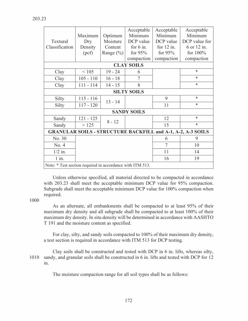
172
Textural Classification
Maximum Dry
Density (pcf)
Optimum Moisture Content
Range (%)
Acceptable Minimum DCP value
for 6 in. for 95%
compaction
Acceptable Minimum DCP value for 12 in. for 95%
compaction
Acceptable Minimum
DCP value for 6 or 12 in. for 100%
compaction CLAY SOILS
Clay < 105 19 - 24 6
* Clay 105 - 110 16 - 18 7 * Clay 111 - 114 14 - 15 8 *
SILTY SOILS Silty 115 - 116
13 - 14 9 * Silty 117 - 120 11 *
SANDY SOILS Sandy 121 - 125
8 - 12 12 * Sandy > 125 15 *
GRANULAR SOILS - STRUCTURE BACKFILL and A-1, A-2, A-3 SOILS No. 30
6 9 No. 4 7 10 1/2 in. 11 14 1 in. 16 19
Note: * Test section required in accordance with ITM 513. Unless otherwise specified, all material directed to be compacted in accordance with 203.23 shall meet the acceptable minimum DCP value for 95% compaction. Subgrade shall meet the acceptable minimum DCP value for 100% compaction when required. 1000 As an alternate, all embankments shall be compacted to at least 95% of their maximum dry density and all subgrade shall be compacted to at least 100% of their maximum dry density. In situ density will be determined in accordance with AASHTO T 191 and the moisture content as specified. For clay, silty, and sandy soils compacted to 100% of their maximum dry density, a test section is required in accordance with ITM 513 for DCP testing. Clay soils shall be constructed and tested with DCP in 6 in. lifts, whereas silty, sandy, and granular soils shall be constructed in 6 in. lifts and tested with DCP for 12 1010 in. The moisture compaction range for all soil types shall be as follows:
203.23

173
Soil Type Moisture Compaction Range Clay (< 105 lb/cu ft) -2 to +2% of optimum moisture content Clay (105 - 114 lb/cu ft) -2 to +1% of optimum moisture content Silty and Sandy (> 114 lb/cu ft) -3% to optimum moisture content Granular 5 to 8%
DCP testing will be performed in accordance with the Frequency Manual at random locations determined in accordance with ITM 802. Moisture testing will be performed in accordance with the Frequency Manual. 1020 If the embankment material is too wet or too dry, either the material shall be aerated to remove excess moisture or watered and disked to increase the moisture content, until in either case the moisture content is within the specified range. Sufficient moisture tests will be made to ensure that this range is maintained throughout the embankment. The embankment material shall be placed in uniform level layers, left properly shaped as set out above, and compacted with approved compacting equipment. Compacting equipment shall include at least one 3-wheel roller or other approved compacting equipment capable of providing a smooth and even surface on the 1030 embankment as directed. Each lift shall be disked or treated by some other mechanical means which shall ensure the breaking up of any existing lumps and clods. The loose depth of each lift shall be such that the required compaction can be obtained, but in no case shall it exceed 8 in. Where a tamping roller is used, the loose depth of lift shall not exceed the length of the tamper feet. The surface area of the end of each foot of the tamping roller shall be no less than 5 1/2 sq in. 1040 203.23.1 Coal Ash Embankment When used as borrow, coal ash shall be placed in the embankment, compacted, and encased upon delivery to the project unless stockpiled at an approved location and in an approved manner. The Contractor shall include appropriate measures to prevent the movement of coal ash from the embankment area. These measures include, but are not limited to controlling stormwater runoff and fugitive dust. The top of coal ash embankments shall be temporarily encased if embankment construction will be delayed for more than seven days or if weather conditions warrant encasement. Control measures shall 1050 be amended into the SWQCP in accordance with 205. Coal ash shall not be mixed with other embankment materials within a given lift of the embankment.
203.23.1

174
Coal ash shall not be placed in any of the following locations: 1. Below existing ground. 2. Within a 100 ft horizontal distance of a stream, river, lake, 1060
reservoir, wetland, karst feature or any protected environmental area.
3. Within a 150 ft horizontal distance of a well, spring, pond
or other ground source of water. 4. MSE wall backfill. 5. As encasement material. 1070 6. Within the limits of subgrade treatment. 7. Directly in contact with any permanent metallic
construction materials. The loose depth of each lift of coal ash shall not exceed 8 in. Compaction of each lift shall begin at the outer edge and progress towards the center of the embankment using a maximum 10 t roller. The moisture content shall be controlled within -2 and +2 percentage points of the 1080 optimum moisture content determined in accordance with AASHTO T 99. Compaction will be determined by DCP testing in accordance with ITM 509. The DCP criteria for compaction acceptance will be as follows: 1. A minimum blow count of 7 for a 6 in. compacted lift for
fly ash. 2. A minimum blow count of 16 for a 12 in. compacted depth
of bottom ash consisting of two compacted 6 in. lifts. 1090 The Contractor shall coordinate with the Department’s Geotechnical Engineering Division to determine the minimum blow count for a mixture of fly ash and bottom ash. Lateral underdrains shall be installed at the bottom of coal ash embankments. Lateral underdrains shall be trenched into the embankment after it has reached an elevation at least 2 ft above existing ground. The bottom of the trench shall be at the top of existing ground with adjustment made for slope of the drain. The trench shall be located within 2 ft of the toe of slope. The trench shall be backfilled with the coal ash material used for the embankment, mechanically compacted to meet the 1100 compaction requirements herein. Lateral underdrains shall be 6 in. diameter Type 4
203.23.1

175
pipe in accordance with 715.02(d) and shall be enclosed in geotextile for underdrains in accordance with 918.02. Lateral underdrains shall be spaced a maximum of 100 ft longitudinally along the centerline of the embankment, shall outlet into the roadside ditch on each side of the embankment, shall extend a minimum of 8 ft horizontally into the embankment, and shall be sloped at a minimum of 0.2%. Underdrain outlet protectors in accordance with 718.06 shall be installed at the outlet end of each lateral underdrain. 1110 Coal ash shall be encased on all sides with cohesive soil. The cohesive soil shall be a silty loam, sandy clay, silty clay, sandy clay loam, clay, or a silty clay loam in accordance with 903.02. All cohesive soils shall have a minimum clay content of 10%. Encasement shall be as follows:
Total Finished Embankment Height
Encasement (measured horizontally)
Less than 10 ft 2 ft
10 ft to 20 ft 3 ft
Greater than 20 ft 4 ft Encasement material shall be placed and compacted concurrently with the coal ash lifts. 1120 The top of the coal ash embankment shall be encased with a minimum of 1 ft of cohesive soil beneath the bottom of subgrade. 203.24 Method of Making Strength, Stiffness and Density Tests The strength of chemically modified or compacted soils will be determined by DCP in accordance with ITM 509. The stiffness of chemically modified soils or aggregates will be determined by the LWD in accordance with ITM 508. 1130 The density of soils and aggregates, as a percent of compaction, will be based on the maximum dry densities unless otherwise specified or directed. DCP field compaction tests will be performed in accordance with 203.23. LWD and density field compaction tests will be performed in accordance with this section. The required compaction shall be obtained before additional material is placed. (a) Laboratory The DCP criteria will be established on representative soils by performing ASTM D1140, AASHTO T 88, AASHTO T 89, AASHTO T 90, and AASHTO T 99 using 1140 Method A for soils and Method C for granular materials.
203.24

176
The optimum moisture content, maximum dry density, and gradation of aggregates will be determined by performing AASHTO T 99 Method C, AASHTO T 11, and AASHTO T 27 on representative samples of the aggregates. (b) Field The soil strength of compacted soils or compacted chemically modified soils will be determined by DCP in accordance with ITM 509 and the stiffness of chemically modified soils or aggregates will be determined by LWD in accordance with ITM 508. 1150 The moisture content will be determined in accordance with ITM 506 or AASHTO T 255. As an alternative, in situ field density may be determined in accordance with AASHTO T 191, except as listed below. The maximum dry density of the soil will be determined by ITM 512 1. If AASHTO T 191 is used, the sand used for the test shall
be silica sand in accordance with the gradation as follows: 1160 Passing the No. 20 (850 μm) sieve - 98 to 100% Passing the No. 40 (425 μm) sieve - 0 to 35% Passing the No. 70 (212 μm) sieve - 0 to 2% Sand such as Wedron Silica Sand No. 4075 or Ottawa 2.8
Blasting Sand has been found to be acceptable. 2. If particles larger than those that can pass through a No. 4
(4.75 mm) sieve for soil and a 3/4 in. (19 mm) sieve for granular material are encountered, corrections shall be 1170 made so that the density obtained is for the minus No. 4 (4.75 mm) or 3/4 in. (19 mm) only. After the densities are determined, the percent compaction will be computed by the following formula:
Percent Compaction=In Place Density, pcf
Maximum Density, pcf x 100
3. Other approved types of field density tests may be used for
control purposes after density values corresponding to those obtained by either of the methods set out above have 1180 been established.
4. All references to soils in these methods of tests shall be interpreted to mean either or both soil and granular materials.
203.24

177
Acceptance testing of chemically modified soils and coarse aggregates will be determined by LWD testing in accordance with ITM 508. The allowable deflection will be determined from a test section or will be specified. Test sections shall be constructed in accordance with ITM 514 in the presence of a representative of the 1190 Geotechnical Engineering Division for other materials not included in the Tables to determine the maximum allowable deflection. The compaction procedures shall be in accordance with 203.23, 215, 301, 302, and 303. Proofrolling of compacted aggregate shall be performed in accordance with 203.26. The allowable average deflection and maximum deflection for chemically modified soils and aggregate over chemically modified and untreated soils shall be in accordance with the following:
Table 1. Allowable Average Deflection and Maximum Deflection for Chemically 1200 Modified Soils and Aggregate over Chemically Modified Soils.
Material Type Allowable Average Deflection (mm)
Maximum Deflection at a Single Test Location (mm)
Lime Modified Soil 0.35 Cement Modified Soil 0.31 Aggregate over Lime Modified Soil 0.35 Aggregate over Cement Modified Soil 0.31
Table 2. Aggregate over Untreated Soils: Where Proofrolling Can Be Performed
Material Thickness Allowable Average Deflection (mm)
Maximum Deflection at a Single Test Location (mm)
6 in. Thick Coarse Aggregate No. 53 0.57* 12 in. Thick Coarse Aggregate No. 53 0.40** 18 in. Thick Coarse Aggregate No. 53 0.31 0.35** * When deflection exceeds this value, the area shall be recompacted or undercut as
directed. The failed area will be delineated prior to excavation. Deflection will be measured based on the top 6 in. thick coarse aggregate No. 53 material placed for undercut.
** The Contractor shall recompact the coarse aggregate No. 53 in accordance with 301.06.
203.24

178
Table 3. Aggregate over Untreated Soils: Where Proofrolling Cannot be Performed
Material Thickness Allowable Average Deflection (mm)
Maximum Deflection at a Single Test Location (mm)
6 in. Thick Coarse Aggregate No. 53 0.65* 12 in. Thick Coarse Aggregate No. 53 0.52** 18 in. Thick Coarse Aggregate No. 53 0.49** * When deflection exceeds this value, the area shall be recompacted or undercut as
directed. The failed area will be delineated prior to excavation. Deflection will be measured based on the top 6 in. thick coarse aggregate No. 53 material placed for undercut.
** The Contractor shall recompact the coarse aggregate No. 53 in accordance with 301.06. Note: The Engineer will perform the moisture test on in-situ soils prior to placement of coarse
aggregate. If the result of the moisture test is > 13%, the Engineer will contact the Department’s Geotechnical Engineering Division.
1210 Acceptance of the compaction of chemically modified soils or aggregate will be determined by averaging three LWD tests obtained at a random station determined in accordance with ITM 802, for each 1,400 cu yds of chemically modified soil or for each 800 t of compacted aggregate. Where the construction area is 8 ft wide or more, the location of the three tests will be at 2 ft from each edge of the construction area and at 1/2 of the width of the construction area. Where the construction area is less than 8 ft wide, the location of the three LWD tests will be spaced at 1/2 of the width of the construction area and spaced 5 ft apart in the longitudinal direction. The average deflection shall be equal to or less than the maximum deflection allowed in the tables above or determined by the test section. 1220 203.25 Embankment Without Stiffness Control When aggregate is used for embankment construction and it is not possible to perform stiffness testing in accordance with ITM 508 or strength testing in accordance with ITM 509, such material shall be compacted with several passes of crawler-tread equipment or with approved vibratory equipment, or both. The equipment weight shall be at least 10 t. The materials shall be placed in lifts not to exceed 9 in. loose measurements, or as directed by the Engineer. Each lift shall be compacted with a minimum of five passes. The tread areas shall overlap enough on each trip so that the entire embankment is compacted uniformly. When the embankment reaches 24 in. 1230 below the proposed subgrade elevation, proofrolling shall be performed in accordance with 203.26. Proofrolling shall also be performed at every 5 ft of fill placed. Any defect shall be corrected as directed. Upon acceptance, a layer of geotextile in accordance with 918.02(a) Type 2B, shall be placed and the remaining embankment shall be constructed with No. 53 aggregate in accordance with 301. At locations inaccessible to the above compacting equipment, the required compaction shall be obtained with approved mechanical tamps or vibrators, in which
203.25

179
case the depth of lifts, loose measurement, shall not exceed 4 in. 1240 203.26 Proofrolling When proofrolling is specified, the work shall be performed with an on-highway dump truck with a minimum tire pressure of 90 psi. Proofrolling for original ground or embankment construction shall be performed using a dump truck weighing at least 15 t. Proofrolling for subgrade preparation shall be performed using a dump truck weighing at least 33 t. All proofrolled surfaces shall be covered completely with a single pass. Operating speed of the proofrolling truck shall not exceed 2 mph. 1250 Deflections or rutting in excess of 1/2 in. shall require remediation of the surface as directed. Deflection or rutting in excess of 3 in. shall require corrective remediation measures and the Department’s Geotechnical Engineering Division will be contacted. Proofrolling shall be performed after remediation measures on embankment or subgrade prior to the placement of additional material. There shall be one or two complete coverages as directed. Roller marks, irregularities, or failures shall be corrected. 203.27 Method of Measurement 1260 (a) Contract Quantity The quantities of excavation for which payment will be made will be those shown in the Schedule of Pay Items for the pay items, provided the project is constructed to the lines and grades shown on the plans. Unless otherwise specified, the project limits will be considered as one balance. If earthwork balances are shown on the plans, they are for information only. When the plans have been altered or when disagreement exists as to the accuracy of the plan quantities in any balance, or the contract quantity, either party shall have 1270 the right to request and cause the quantities involved to be measured in accordance with measured quantities. When the quantities are measured for payment, the original plan cross sections plotted on the plans shall be used as original field cross sections. Additional original cross sections may be interpolated at points where necessary to determine the quantities more accurately. If the Contractor has acceptable engineered data that indicates an excavation quantity that is in error by more than 2%, then additional measurements will be performed on the areas in question and payment will be made for actual quantities. (b) Measured Quantities 1280 When payment is specified on a volume basis, all accepted excavation and borrow will be measured in its original position by cross sectioning the area excavated, which measurements will include over-breakage or slides in common excavation and unclassified excavation, not attributable to carelessness, and authorized excavation of
203.27

180
rock, shale, peat, or other unsuitable material. Volumes will be computed from cross section measurements by the average end area method. Measurement for payment will not include material excavated beyond authorized cross sections. Where material is excavated beyond authorized cross sections and wasted without authority, the material so wasted will be measured and deducted from 1290 the excavation quantities. Unless otherwise authorized, the amount of waste to be deducted, when common excavation, rock excavation, unclassified excavation, borrow, or other excavation has been wasted along embankments or elsewhere without authority shall be that portion of the embankment or fill which is outside a 1/4 to 1 slope in excess of that shown on the plans, and all portions outside a line from the shoulder point to a point 4 ft, measured horizontally, outside the theoretical toe of the slope. In determining waste, no tolerance in widths of shoulders will be allowed unless additional widths are authorized in writing before shoulders are finally constructed. Measurements will be made for unsuitable materials actually excavated and 1300 removed to obtain proper compaction in cut sections and in foundations for fill sections. Where it is impracticable to measure material by the cross section method due to the erratic location of isolated deposits, acceptable methods involving three-dimensional measurements may be used to measure the material in its original position. The cubic yards of peat excavated will be determined by cross sections, as described above, with the final cross sections taken after complete excavation and 1310 before placing granular backfill, if peat is removed by excavation. When removal by displacement is necessary, final cross sections will be derived from cased test holes through the completed granular treatment in accordance with 203.17. Such test holes shall be located at intervals which clearly define the bottom of the treatment between lateral limits. Pay quantities of peat excavation will be limited to the volume of peat lying between vertical lines as shown on the plans for lateral limits. Cased test holes and exploratory drilling will be measured by the linear foot; B borrow by the cubic yard, in accordance with 211.09. However, measurement to neat lines will not apply unless specifically designated. Breaking pavement will be 1320 measured by the square yard in place before breaking. (c) Measurement on a Linear Basis Linear grading will be measured by the linear foot. Measurement will be made once along each survey centerline for all linear grading completed on the line. Deductions will be made for bridges. Classes of excavation, except for required borrow, involved in linear grading will not be measured. (d) Measurement of Excavation Items on a Weight Basis A pay item for excavation may be specified to be measured and paid for on a 1330
203.27

181
weight basis. When a weight basis is specified, the material will be weighed in accordance with 109.01(b). (e) Measurement of Embankments When specified, embankments constructed will be measured in accordance with the terms set forth. When embankment is specified as a separate pay item, the volume as constructed will be measured in place in accordance with 203.27(b). However, no measurement will be made for excavation or borrow, except as noted herein. The volume shall be 1340 computed in cubic yards from the dimensions of the embankment cross sections and to the depth below completed grade to which this method of construction applies. No shrinkage factor shall be used in computing the embankment volume. Measurements will be made for unsuitable materials actually excavated and removed to obtain proper compaction in cut sections and in foundations of fill sections in accordance with 203.27(b). B borrow from off the right-of-way placed within embankment areas will be measured in accordance with 211.09. (f) Measurement of Borrow Borrow will be measured by the cubic yard. Except as otherwise provided herein, 1350 borrow will be cross sectioned in its original position before excavation is started, again after it is completed, and the volume computed by the average end area method. No material shall be excavated as borrow until unsuitable material, vegetation, and other perishable matter have been removed and cross sections taken over the cleared area. None of this removed unacceptable material shall be moved back into the pit before final sections are taken. If borrow is obtained from a source where it is impracticable to measure the material in its original position, such material will be measured after being placed in embankment with no allowance made for a compaction factor. The borrow may be 1360 measured in truck beds in accordance with 211.09 for contracts having a proposal quantity less than 500 cu yds. If such source is contemplated, approval shall be obtained in writing before this part of the work is started. For quantities less than 5,000 cu yds, the material may be weighed in accordance with 109.01(b) and converted from pounds shown on the weigh tickets to cubic yards using a factor of 3,000 lb/cu yd. If borrow is specified outside the limits of B borrow and if the requirements of the work do not otherwise prohibit, material in accordance with these specifications for B borrow, may be furnished and placed at the contract unit price for borrow, in which 1370 case measurement will be in accordance with 211.09. Measurement of borrow in accordance with 211.09 will be limited to nominal quantities outside the limits of structure backfill. The quantity of borrow measured for payment will not exceed the theoretical quantity of B borrow furnished.
203.27

182
(g) Measurement of Embankment Foundation Soils Treatment Mechanical treatment of embankment foundation soils will be measured by the square yard. Chemical treatment of embankment foundation soils will be measured in accordance with 217. 1380 (h) Measurement of Water for Shale, Shale and Soft Rock Mixtures, or Soft Rock When payment for water for shale is specified in the contract, the water for shale used will be measured by the 1,000 gal. by means of calibrated tanks or distributors, or by means of accurate water meters. When water for shale is not specified as a pay item in the contract, the water for shale that is used will not be measured directly. Such measurement will be included in that required for other pay items. (i) Lump Sum If the pay unit for a pay item for excavation is lump sum, no measurement will be 1390 made. (j) Measurement of Exploratory Cores Exploratory cores will be measured by the linear foot of rock core. (k) Measurement of Coal Ash If coal ash is used as borrow, it will be measured in accordance with 203.27(f). If coal ash is encountered during excavation, it will be measured as common excavation in accordance with 203.27. 1400 203.28 Basis of Payment The accepted quantities of excavation and embankment will be paid for at the contract price per unit of measurement for each of the pay items listed below which is included in the Schedule of Pay Items. Common excavation and unclassified excavation will be paid for on the unit basis of contract quantities in accordance with 203.27(a), without any quantity limit, unless otherwise shown in the Schedule of Pay Items. Combined quantities of borrow, common and unclassified excavation not exceeding 15,000 cu yds will be paid for on the basis of contract quantities in accordance with 203.27(a) with no adjustment to plan shrinkage factor. Except as 1410 noted above, borrow, as well as all other excavation, will be paid for on the basis of measured quantities in accordance with 203.27(b), unless otherwise shown in the Schedule of Pay Items. Linear grading will be paid for at the contract unit price per linear foot. If the class of excavation is linear grading, additional borrow and the excavation of and disposal of unsuitable material not included as pay items will be paid for as follows: If the total quantity exceeds 5,000 cu yds at a given location, it will be paid for at 1420 $8.00 per cu yd. If the total quantity exceeds 1,000 cu yds, but does not exceed 5,000
203.28

183
cu yds at a given location, it will be paid for at $12.00 per cu yd. If the total quantity does not exceed 1,000 cu yds at a given location, it will be paid for at $15.00 per cu yd. Linear grading includes only such grading within the construction limits. All grading the Contractor is directed to perform outside the construction limits, except for the Contractor’s convenience, will be paid for in accordance with 104.03 or 109.03 unless such grading is shown on the plans or in the Contract Information book. 1430 Existing concrete building foundations, concrete walls, concrete columns, or concrete steps not visible and not shown on the plans within the limits of the planned excavation will be paid for at 10 times the contract unit price per cubic yard for common or unclassified excavation, whichever is set out as a pay item. Unless a waste area is established within the contract limits, the minimum pay for this work will be $80.00 per cu yd. Excavation and disposal of unsuitable material will be paid for at the contract unit price for the class of excavation involved. If no such pay item is included in the contract and embankment is included as a pay item, the excavation and disposal will 1440 be paid for at the contract unit price for embankment, unless otherwise directed. If there is no pay item for rock excavation and such is encountered, it will be paid for at $125.00 per cu yd for quantities less than or equal to 100 cu yds. For quantities greater than 100 cu yds pay will be determined in accordance with 104.03. If there is no pay item for common excavation and if such is encountered, it will be paid for at the contract unit price per cubic yard for borrow. If the contract includes a pay item for waterway excavation, and if class Y 1450 excavation is encountered and there is no pay item for such, the class Y excavation will be paid for at 10 times the contract unit price per cubic yard for waterway excavation, or $100.00 per cu yd, whichever is greater. If the contract does not include a pay item for waterway excavation and such is encountered, pay will be determined in accordance with 104.03. If excavation is necessary to investigate or to seal sinkholes, or to explore underground drainage, the accepted quantity involved at each location will be paid for as follows. The first 10 cu yds or fraction thereof will be paid for at 10 times the 1460 contract unit price for the class of excavation encountered. The next 40 cu yds or fraction thereof will be paid for at seven times the contract unit price for the class of excavation involved. Additional quantities will be paid for at three times the contract unit price per cubic yard for the class of excavation involved. Material overlying the peat deposits which is excavated and used in embankment will be considered as common excavation and will be paid for as such. Excavation for
203.28

184
standard side ditches or other side ditches which are constructed through peat areas at locations shown on the plans, or where directed, will be paid for at the contract unit price per cubic yard for common excavation. 1470 Mechanical treatment of embankment foundation soils will be paid for by the square yard as embankment foundation soils treatment. Cased test holes and exploratory drilling will be paid for at the contract unit price per linear foot. If there is no pay item for borrow, the costs of identifying the borrow areas, the archeological investigation, all required permits, and the opening and closing of the borrow area will be included in a change order developed in accordance with 109.05 1480 and paid for as borrow area. If the contract documents do not identify excess excavation or require removal of any items from the site, the cost of identifying a disposal area, archeological investigation, all required permits, and the opening and closing of the disposal area will be included in a change order developed in accordance with 109.05 and paid for as disposal area. If a type of excavation for which no pay item exists is required and the new type of excavation requires the Contractor to use equipment not otherwise being used on 1490 the contract, all cost involved in determining the type of equipment necessary to complete the work and making this equipment available for the project will be included in a change order developed in accordance with 109.05 and paid for as additional mobilization and demobilization. If a type of excavation for which no pay item exists is required and the new type of excavation requires additional traffic control not shown on the plans or results in traffic control being required for an additional period of time, all cost involved in providing the additional traffic control will be included in a change order developed in accordance with 109.05 and paid for as additional maintaining of traffic. 1500 Coal ash used as borrow will be paid for at the contract unit price for borrow. Excavation of coal ash will be paid for at the contract unit price for common excavation. Payment will be made under: Pay Item Pay Unit Symbol 1510 Borrow ....................................................................................... CYS Breaking Pavement .................................................................... SYS Cased Test Holes ....................................................................... LFT
203.28

185
Embankment .............................................................................. CYS Embankment Foundation Soils Treatment ................................ SYS Excavation, Common ................................................................ CYS Excavation, Peat ........................................................................ CYS Excavation, Rock ....................................................................... CYS Excavation, Unclassified ........................................................... CYS Excavation, Waterway ............................................................... CYS 1520 Excavation, Y ............................................................................ CYS Exploratory Cores ...................................................................... LFT Exploratory Drilling .................................................................. LFT Linear Grading .......................................................................... LFT Water for Shale .......................................................................... kGAL. If embankment is specified as a pay item, borrow and common excavation, unless otherwise specified, will not be paid for directly. The costs thereof shall be included in the cost of embankment. Such price shall be full compensation for preparation of the natural ground on which the embankment is to be placed and excavating, hauling, 1530 placing, spreading, and compaction of materials in accordance with 203.23. The costs of labor, equipment, tools, and necessary incidentals shall be included in the cost of embankment. The cubic yards of suitable material used in the embankment excavated from the right-of-way and paid for under a specific pay item will not be deducted from the embankment quantities. The quantity of material to be paid for as B borrow and placed within the embankment area as specified will be deducted from the quantity of embankment. The costs of excavating, backfilling, disposal of surplus material, labor, equipment, tools, and necessary incidentals necessary shall be included in the cost of 1540 excavation required to seal sinkholes or explore underground damage. The costs of all excavated or displaced peat, regardless of depth, peat disposal, temporary surcharge, machine operation, and machine availability shall be included in the cost of peat excavation. However, the Department may provide temporary right-of-way for peat disposal when so specified. Cost for providing additional lighting for grading operations shall be included in the cost of other pay items in this section. 1550 No payment will be made for the construction or restoration of borrow or disposal sites. No payment will be made for the inspection of disposal and borrow areas for wetland identification, obtaining of permits, the development and construction of all mitigation measures, or the fulfillment of permit requirements. The cost of boring the holes, casings and fittings, labor, equipment, tools, and all necessary incidentals shall be included in the cost of cased test holes or exploratory drilling. 1560
203.28

186
The cost of reshaping scoured or eroded areas shall be included in the cost of other pay items. The cost of surface roughening shall be included in the cost of other pay items. The cost of identification of borrow areas, archeological investigations, and changes to construction operations caused by the identification of an archeological site shall be included in the cost of borrow, unless otherwise agreed to in writing. 1570 The cost of all classes of excavation, except required borrow, within the limits of linear grading shall be included in the cost of linear grading. The cost of geotextiles shall be included in the cost of other pay items. The costs for the use of coal ash in embankment construction, including, but not limited to testing of the material, encasement, additional erosion and sediment control measures, lateral underdrains and all incidentals shall be included in the cost of other pay items in this section. 1580
SECTION 204 – GEOTECHNICAL INSTRUMENTATION 204.01 Description This work shall consist of providing, installing and maintaining of geotechnical instrumentation including settlement plates, settlement stakes, lateral stakes and standpipe piezometers as directed and in accordance with 105.03.
MATERIALS 204.02 Materials 10 Materials shall be in accordance with the following: B Borrow ............................................................................ 211.02 Coarse Aggregate, Class D or Higher, Size No. 53. ........... 904.03 Ottawa Sand* ..................................................................... AASHTO T 252 Structure Backfill, Size No. 30 .......................................... 904.05 * Ottawa Sand shall have a minimum permeability of 25 ft/day. Bentonite chips shall consist of commercially processed angular fragments of pure bentonite, without additives. 20 Bentonite-cement grout shall consist of a mixture with the ratio of 25 lb of bentonite with 94 lb of portland cement, Type I in accordance with 901.01(b) and 30 gal. of water.
204.01
187
CONSTRUCTION REQUIREMENTS 204.03 Settlement Plates Settlement plates consist of 1/2 in. by 3 ft by 3 ft steel plate equipped with sections of 3/4 in. pipe and 2 in. galvanized threaded pipe and couplings to act as a cover or 30 guard. (a) Installation Requirements Each settlement plate shall be placed on a horizontal plane consisting of a compacted leveling layer of B borrow, whose surface is not less than 1 ft below the elevation of the adjacent area. The first section of pipe shall then be installed by welding to the settlement plate. The bottom elevation of the settlement plate will be recorded. The area is backfilled with B borrow and thoroughly compacted. The couplings shall be tack welded and the top elevation of the first pipe section will be recorded before starting the first lift of grading operations. 40 The pipe sections for the settlement plates shall be 3/4 in. steel pipe, 4 ft long and threaded on both ends with proper fittings so that such pipe sections can be extended vertically from the center of the plates up through the new embankment as it increases in height during grading operations. A cover pipe 2 in. shall be slipped over and centered on the standpipe, and not welded to plates. The 3/4 in. steel and cover pipes shall extend a minimum of 2 ft or more above the grade of the new embankments at all times during grading operations and monitoring period. Settlement stakes and lateral stakes, if required, shall be installed as shown on the 50 plans or as directed by the Engineer. The stakes shall be 3/4 in. by 4 ft steel rods and shall be driven at least 12 in. into the ground. These stakes shall be set firmly in a vertical position and initial readings will be taken. B borrow shall be used as compaction material around the settlement plates and pipes and shall be placed in accordance with the applicable requirements of 211. (b) Instrument Readings and Settlement Period During the construction of the embankment, elevation readings will be taken on all settlement plate extension pipes and settlement stakes at the end of each seven-day 60 period, or more frequently if required. After the embankment is constructed to the bottom of the subgrade, additional readings will be taken every seven days until the settlement rate per week is 1/4 in. or less for four consecutive weeks. The monitoring period may be reduced as directed by the Department’s Geotechnical Engineering Division. If the results of any readings indicate that the new embankment has settlement greater than 1/4 in., the monitoring period will be extended until the settlement requirements are met. 70 Settlement stakes will be used to measure the vertical movement, in conjunction
204.03

188
with settlement plates if specified. Settlement stakes and settlement plates will be monitored at the same time and interval. Measurements will be made to the nearest 1/4 in. Within one day of the readings, settlement data will be sent electronically to the Department’s Geotechnical Engineering Division and will be subject to approval. Lateral stakes will be used to monitor horizontal movement of the ground or new fill. If lateral movement is noticed during the construction of the fill, the work will be suspended and the Department’s Geotechnical Engineering Division will be contacted. Measurements will be made to the nearest 1/4 in. 80 Settlement plates, extension pipes, cover pipes, and stakes shall be protected during construction operations and during the monitoring period. (c) Protection and Maintenance The settlement stake and settlement plate shall remain in a vertical position. The Contractor shall ensure that settlement plates and settlement stakes are not damaged or displaced. Settlement stakes and settlement plates deviating from a vertical position, becoming uncoupled, or broken shall be repaired or replaced by the Contractor, as directed by the Engineer. 90 The Contractor will not be held responsible for repair or replacement of any settlement plate assembly which is damaged as a result of instability of the embankment caused by factors beyond the control of the Contractor, as determined by the Engineer. 204.04 Standpipe Piezometers The standpipe piezometers shall be installed by a geotechnical consultant on the Department’s Qualified Geotechnical Consultant’s List prior to placing the first lift of embankment. Piezometer consists of a 1/2 in. leak proof, flush-coupled Schedule 80 100 PVC pipe or ABS standpipe extending to the surface of the embankment with an attached polyethylene tip in accordance with AASHTO T 252. (a) Installation Requirements A separate water-monitoring borehole shall be installed outside the influence of the fill as shown on the plans. This shall be a minimum 2 in. diameter borehole, cased with slotted pipes, drilled to a recommended depth and location or as directed by the Engineer, to establish groundwater elevation prior to piezometer installation. The installation of the standpipe piezometer shall precede placement of any 110 embankment by at least two weeks to allow time for testing of the installation. The piezometer shall be maintained and protected during the embankment construction. The hollow stem auger shall be advanced to an approximate depth of 6 in. below the recommended piezometer tip elevation. Augers shall be cleaned and washed inside for their full length, until the wash water runs clear. The auger shall be withdrawn 6 in. by means of jacking or other steady pull operations. The hole shall be filled to the bottom with saturated Ottawa sand and
204.04

189
tamped with an annular tamping hammer. The elevation shall be measured and provided to the Engineer. 120 The tip shall be attached to the standpipe and tested for free flow of water. The bottom end of the tip shall be plugged and soaked in water if a porous stone tip is used. The tip and standpipe shall be filled with clean water. The tip shall be lowered into the auger until it rests on the top of the sand placed and the elevation of the tip should be documented. Excess head shall be maintained in the standpipe during lowering to ensure that a small amount of water flows out of the tip. The auger shall then be pulled or jacked a distance equal to the length of the tip in increments of 6 in. The hole shall be filled with water saturated Ottawa sand at each 130 increment. This layer of sand shall not be tamped in order to avoid damage to the tip. The auger shall be raised 12 in. and the hole filled with saturated Ottawa sand in 6 in. increments until the backfilling reaches a minimum of 6 in. below the elevation of the strata change or as directed by the Engineer. In locations where there is no strata change, the Ottawa sand shall be placed a minimum of 12 in. above the top of the tip. The augers shall then be raised and the hole sealed with bentonite chips in accordance with AASHTO T 252 which shall be placed in 6 in. lifts. The top of the seal shall be a minimum of 6 in. above the strata break. A weighted line shall be used 140 to ensure the bentonite seal is in place. The remainder of the hole shall then be backfilled with bentonite-cement grout as the augers are withdrawn. The riser pipe shall be kept in tension and shall be centered in the auger while backfilling. Depths for various stages shall be recorded on the Engineer’s logs. If the piezometer location is not in an area of proposed fill, an approximately 3 ft long protective metal cover shall be installed at the top with approximately 2 ft below the surface and 12 in. above the surface. A 12 in. diameter by 6 in. thick circular pad of coarse aggregate shall be filled around the cover. A lockable cap shall be securely attached onto the protective metal cover. 150 If the piezometer location is in an area of proposed fill, a PVC casing shall be used around the piezometer standpipe in order to protect the pipes during embankment construction. B borrow shall be placed and compacted around the casing without disturbing the casing. The casing and standpipe shall be extended as the fill is placed, by adding extra lengths not to exceed 5 ft. The top of the standpipe shall be at least 12 in. above the grade of the new fill. Each time the casing and standpipe are extended, the casing shall be filled with structure backfill. The last extension of pipe shall be of such length that 160 it extends 12 in. above grade. It shall be filled with structure backfill to within 9 in. of the top of the casing. A 12 in. diameter by 6 in. thick circular pad of coarse aggregate shall be filled around the pipes. A lockable cap shall be securely attached onto the protective cover.
204.04

190
When the standpipe is completed it shall be checked for obstructions by dropping a weighted line through the pipe. The standpipe shall then be filled with water and periodic readings made of the water level until the groundwater level is stabilized. Hydrostatic time lag required for equalization will be provided by the Geotechnical report. If required, the standpipe shall be flushed and retested at the direction of the 170 Engineer. Groundwater readings shall be provided to the Engineer. Standpipe piezometers, and cover pipes shall be protected during construction operations and during the monitoring of the fill. In the event of damage, fill construction shall be suspended in this area until the piezometer is restored. (b) Readings and Maintenance of Piezometer The Engineer will conduct and record all observations and measurements required to determine natural groundwater elevations and pore pressures induced by embankment construction. Monitoring intervals will be once every day for the first 180 seven days, once every other day for the next eight, and then, once every three days through the end of construction of the fill. The elevation of the natural groundwater existing at the time of installation, prior to placement of any fill, will be used as a reference to determine baseline pore pressures. Groundwater and pore pressure test results will be made available to the Contractor. The pore pressure measurement in conjunction with the settlement data will be sent electronically to the Department’s Geotechnical Engineering Division within one day of the readings, and will be subject to approval. If it is determined that pore-water pressures have not sufficiently dissipated, fill placement shall be suspended, and the 190 monitoring period extended as directed. If monitoring is to be continued after paving in a traffic accessible area, then the pipe shall be cut off 6 in. below the finished grade and a handhole in accordance with 807.09, shall be installed for monitoring access. When the evaluation is completed, the water monitoring borehole and piezometers shall be backfilled with bentonite-cement grout. 204.05 Method of Measurement Settlement plates, settlement stakes, lateral stakes, standpipe piezometers, and 200 water monitoring boreholes will be measured by the number of units installed. 204.06 Basis of Payment Settlement plates, settlement stakes, lateral stakes, standpipe piezometers, and water monitoring boreholes will be paid for at the contract unit price per each. Payment will be made under: Pay Item Pay Unit Symbol 210 Settlement Plate ......................................................................... EACH
204.05

191
Stake, Lateral ............................................................................. EACH Stake, Settlement ....................................................................... EACH Standpipe Piezometer ................................................................ EACH Water Monitoring Borehole....................................................... EACH The cost of furnishing, installing, and maintaining settlement plates, extension pipes, cover pipes, B borrow, structure backfill, coarse aggregate and all necessary incidentals shall be included in the cost of settlement plates. 220 The cost of backfilling water monitoring boreholes will be included in cost of water monitoring boreholes. The cost of handholes, protective covers, bentonite chips, bentonite-cement grout, Ottawa sand, tips, casing, drilling, tubing or PVC pipe, backfilling and measurements will be included in the cost of standpipe piezometers. No additional compensation will be made for any costs incurred related to the repair of settlement plates, pipes, settlement stakes, lateral stakes or standpipe piezometers as the result of damage by the Contractor. 230
SECTION 205 – STORMWATER MANAGEMENT 205.01 Description This work shall consist of furnishing, installing, inspecting, maintaining, and removing BMPs in accordance with 105.03, the Department’s Design SWPPP, the submitted and accepted SWQCP or an approved written site plan developed by the Contractor.
MATERIALS 10 205.02 Materials Materials shall be in accordance with the following: Coarse Aggregate, Class F or Higher ................................. 904.03 Fertilizer ............................................................................. 914.03 Filter Sock .......................................................................... 914.09(h) Geotextile ........................................................................... 918.02 Grass Seed, Temporary ...................................................... 914.02 Manufactured Surface Protection Products ........................ 205.04(c) Metal End Sections ............................................................. 908.06 20 Mulch ................................................................................. 914.05(a) Pipe Drains ......................................................................... 715.02(d) Plastic Net........................................................................... 914.09(g) Revetment Riprap ............................................................... 904.04* Stakes ................................................................................. 914.09(b)
205.02

192
Staples ................................................................................ 914.09(f) Top Soil .............................................................................. 914.01 Water .................................................................................. 914.09(a) * The minimum depth does not apply. 30
CONSTRUCTION REQUIREMENTS 205.03 General Requirements For contracts requiring waterway permits, a Construction Stormwater General Permit, or a 327 IAC 15-5 permit, an SWQCP shall be developed and submitted to the Engineer for review. The Contractor shall furnish, install, inspect, maintain, and remove BMPs for land-disturbing activity areas, and develop an SWQCP in accordance with the Construction Stormwater General Permit or 327 IAC 15-5. The Contractor’s SWQCP 40 shall be a required contract specific component to the Department’s Design SWPPP. The submitted and accepted Contractor’s SWQCP shall interrelate with the Department’s Design SWPPP in order to satisfy the requirements of the Construction Stormwater General Permit, or 327 IAC 15-5. (a) Stormwater Quality Control Plan Development The Contractor’s SWQCP shall be developed by a professional engineer who holds a current CPESC certification or approved equivalent. The SWQCP developer shall be familiar with the project site and be able to develop the SWQCP in accordance with the site conditions. In the event of conflict between requirements, pollution 50 control laws, rules, or regulations of other Federal, State or local agencies, the Contractor’s SWQCP shall adhere to the more restrictive laws, rules, or regulations. The SWQCP developer shall issue clarifications, correct errors and omissions, and revise the SWQCP as required. The Contractor’s SWQCP shall be signed and sealed by the SWQCP developer, as defined above. The Contractor shall develop the SWQCP in accordance with the Construction Stormwater General Permit, 327 IAC 15-5, the IDEM “Indiana Storm Water Quality Manual”, ITM 803, and all other applicable contract documents. 60 (b) Stormwater Quality Control Plan Content The Contractor’s SWQCP shall include the processes and procedures of how the Contractor intends to meet the requirements outlined in this section and in accordance with ITM 803. The Contractor may elect to prepare and submit the SWQCP in multiple phases. The first phase shall show the location, installation, and maintenance of BMPs for the existing topography of the project and identify the total number of proposed construction phases for the contract. Additional phases shall be submitted for review prior to land-disturbing activities for those phases and shall show the progression from 70 the existing topography to final grade. Each phase of the SWQCP shall be modified to meet existing field conditions as needed.
205.03

193
Any individual phase of the SWQCP shall be submitted to the Engineer for review a minimum of 14 calendar days prior to commencing land-disturbing activities for that phase. Upon receipt, the Engineer will perform a review of the submitted phase of the SWQCP within 14 calendar days for acceptance. At a minimum, the SWQCP shall include the following: 80 1. Description of the site. 2. Locations of all proposed soil stockpiles. 3. Locations of all proposed equipment storage areas, fueling
locations, construction trailers, batch plants, and designated concrete truck washout areas.
4. Proposed construction sequence and phasing of BMPs including
plans for installation, inspection, maintenance, and removal of 90 BMPs. The total number of proposed construction phases shall also be specified.
5. Locations of offsite areas that drain onto project limits. The
SWQCP shall include BMPs properly sized and placed to accommodate runoff from outside of the project limits and from within the project limits.
6. Locations of all construction entrances where vehicles and
equipment will enter and exit the site. 100 7. An updated stormwater management budget including a
complete list of all proposed BMPs with price calculations based upon the established unit prices or contract prices. If the total proposed budget exceeds the original stormwater management budget pay item, the Contractor shall submit a Change Order Request form, in accordance with 109.05, to provide an explanation and justification for the additional BMPs. Proposed BMPs and costs will be reviewed by the Engineer. If accepted, the changes shall be included into the 110 SWQCP. Additional accepted costs will be included in the contract in accordance with 109.05.
8. Material handling and spill prevention plan. A plan for the
collection, storage, and disposal of concrete washout wastewater shall be in accordance with 205.03(d).
9. Statements that the BMPs for the project shall, at a minimum,
205.03

194
be inspected each calendar week and by the end of the next work day following every 1/2 in. rain event. 120
10. Provisions to ensure that pollutants such as fuels, lubricants,
asphalt, sewage, wash water, wastewater, or waste from concrete mixing operations, and other harmful materials shall not be discharged into existing bodies of water.
11. Provisions to ensure that all applicable regulations and statutes
relating to the prevention and abatement of pollution shall be complied with in the performance of the contract.
130 When Waters of the United States, wetlands, or other protected resources are identified in the plans within or adjacent to the project limits the following shall also be addressed in the SWQCP: 1. The location of protected resource fencing, or protected
resource signs. These measures shall be used to provide clear delineation for protected resources that have the potential to be impacted by construction operations.
2. A method for conducting work located in or adjacent to bodies 140
of water and protected resources. The method shall indicate how the work in these locations shall be conducted to comply with all conditions of the project permits.
Based on changes in scope, in accordance with 104.02 and 104.03, the Engineer may request a cost breakdown of the stormwater management implementation item. The Contractor’s SWQCP shall incorporate all narrative information, plan sheets, and implementation information necessary for stormwater management utilized for the project. The SWQCP shall include any revisions to the Department’s Design 150 SWPPP and the plans. The revisions shall comply with all known permit requirements applicable to the construction phase of the project including waterway permits, or a Construction Stormwater General Permit, or a 327 IAC 15-5 permit, and those required by the Contractor in accordance with 107.01 and 205.03(c). Electronic files of any plan sheets and narratives included as part of the SWQCP submittal shall be provided in PDF format. On projects requiring an SWQCP, an updated field copy of the SWQCP shall be retained in the office of the Engineer or at a mutually agreed upon location. Any accepted revisions shall be annotated in the field copy of the SWQCP and initialed and 160 dated by the SWQM and the Engineer. A copy of the Contractor’s offsite operations permits for items such as offsite stockpiles, borrow sites, waste sites, or storage areas shall be submitted to the Engineer
205.03

195
prior to any land-disturbing activities at those sites. Revisions to the SWQCP shall be submitted and signed and sealed by the SWQCP developer, for items that are hydraulically sized or calculated such as sediment basins or other similar measures. The SWQM may submit revisions for items that are not hydraulically sized or calculated. Adjustments to the BMPs shall be subject to the 170 Engineer’s acceptance. If a governmental agency or a local governmental authority finds a violation of NPDES or other surface waterway permits provided in the contract documents, if any BMPs are incomplete, or the Contractor’s SWQCP is incomplete, full responsibility shall be borne by the Contractor to make the necessary corrections. In addition, if an assessment, damage judgment or finding, agreed order, fine, or any other expense for a violation of the contract requirements is leveled against the Department, the Contractor shall reimburse the State for that amount within 30 days. The Contractor agrees to indemnify and hold harmless the Department and will reimburse the 180 Department for any assessments, damage judgments or finding, fine, penalty, or other expense relating to this portion of the contract. The Department may withhold the amount owed from the Contractor’s subsequent pay estimates. Delays caused by stop work orders from regulatory agencies, suspension of work orders from the Department, or any other delays caused by inadequate submittals or implementation will be considered Non-Excusable Delays in accordance with 108.08(c). (c) Stormwater Quality Manager On contracts requiring an SWQCP, the Contractor shall designate one person as the contract SWQM. The name of the SWQM shall be furnished to the Engineer at, or 190 prior to, the pre-construction conference. If the designated individual is replaced during the contract, the replacement shall be designated, and notification given to the Engineer within 24 h. The designated individual shall be trained as a level 1 or level 2 SWQM as specified within the contract documents. The SWQM training level shall meet or exceed the level required within the contract documents. 1. Level 1 SWQM A level 1 SWQM shall have successfully completed the Department’s Construction Stormwater Training course and hold a current training verification document for that course. 200 2. Level 2 SWQM A level 2 SWQM shall meet the requirements of 205.03(c)1, and hold a current certification as a CESSWI, or a CISEC, or a CPESC, or an approved equivalent. 3. SWQM Responsibilities The SWQM shall attend the pre-disturbance meeting, in accordance with 205.03(d). The SWQM shall attend at least one meeting with the Contractor, relevant Subcontractors, and the Engineer per calendar month in any month in which weekly and post-event inspections are being completed and work is ongoing. The requirement 210
205.03

196
to attend these meetings may be waived entirely or in part upon written approval from the Engineer. The SWQM shall be responsible for ensuring that the Contractor’s SWQCP has been submitted for review prior to implementation. Implementation of stormwater features shall include installation, inspection, maintenance, and removal of all BMPs. The SWQM shall also be in responsible charge of inspecting the implementation of the Contractor’s SWQCP or the contract site plan. The SWQM shall be in responsible charge of the weekly and post-event inspections. Anyone performing inspections under the responsible charge of the SWQM shall, at a minimum, meet the training 220 requirements of a level 1 SWQM. The SWQM shall accompany personnel from IDEM or other regulatory or governmental agencies, as required, during site visits by those agencies. (d) Pre-Disturbance Meeting On contracts requiring an SWQCP, a pre-disturbance meeting shall be held on-site prior to beginning land-disturbing activities. The meeting invitees shall include the SWQM, the Contractor, the SWQCP Developer, appropriate Department field staff, the District Erosion Control Specialist, District Environmental Section Manager, 230 Ecology and Waterway Permitting Specialist, and all relevant subcontractors for the work being performed. The pre-disturbance meeting shall be held not more than 30 days prior to the start of land-disturbing activities. The following shall be reviewed: 1. Stormwater management implementation including
phasing and sequencing. 2. Permit conditions and authorized impacts. 3. Relevant Unique and Recurring Special Provisions. 240 4. Relevant commitments. If requested in writing, pre-disturbance meeting requirements may be waived in part or in full subject to the approval by the Engineer. No land-disturbing activity shall begin until this meeting has occurred or until written approval to waive the meeting has been received. (e) Temporary BMPs Incoming and outgoing drainage areas impacting a work location shall have 250 temporary BMPs installed as soon as practicable and prior to land-disturbing activities at those locations. Pipe end sections and anchors shall be installed when the structure is installed. If the pipe end sections or anchors cannot be placed at the same time, temporary riprap splashpads shall be placed at the outlets of the pipes until end sections or anchors can be installed.
205.03

197
Adjustments of the BMPs shall be made to satisfy field conditions and shall be subject to the Engineer’s approval. Adjustments made to meet field conditions shall be made as soon as practicable, shall be maintained as necessary, and shall be noted in the SWQCP. 260 The Contractor shall provide a stable construction entrance at the points where construction traffic will enter onto an existing road. Where there is insufficient space for a stable construction entrance, other measures shall be taken to prevent the tracking of sediment onto the pavement. These temporary entrances shall be the responsibility of the Contractor to completely install, inspect, maintain, and remove. A copy of the current manufacturer’s installation and maintenance recommendations shall be provided prior to installation of manufactured BMPs. Shipping, handling, storage, and installation of manufactured BMPs shall be in 270 accordance with the manufacturers’ recommendations or as directed. In the event of conflict between the Department’s specifications and the manufacturer’s recommendations, the Contractor shall adhere to the more restrictive regulation or as directed. Within the SWQCP, the Contractor shall provide a written plan for the collection, storage, and disposal of concrete wastewater that is adequate for the size of the concrete pour, the environmental conditions of the job site, and in accordance with 327 IAC 15-5-7(2) and 327 IAC 15-13-17(2)(F). An emergency concrete washout container shall be available, be part of the material handling and spill prevention plan, 280 and available on-site during concrete pours. Straw bale washout pits will not be allowed. Concrete washout wastewater may either be recycled back into the truck, washed out into an adequately sized and lined roll off container or lined in-ground pit, an approved manufactured product, or taken back to the batch plant. Lining shall consist of a minimum of one sheet of 10 mil plastic, be continuous with no over lapping, and shall be free of leaks. Concrete washout capacity shall not be exceeded. Concrete wastewater shall not be allowed to leak onto the ground, run into storm drains, or into any body of water. Where concrete wastewater leaks onto the ground, all contaminated soils shall be 290 excavated and disposed of in accordance with 202.08 except that all costs associated with excavation and disposal shall be the responsibility of the Contractor. The installation of BMPs shall include those necessary or required by permits at off-site locations such as borrow and disposal areas, field office sites, batch plants, locations where the Contractor’s vehicles enter and leave public roads, and other locations where work pertaining to the contract is occurring. The Contractor’s SWQM shall be responsible for the installation, inspection, maintenance, and removal of these measures. 300 The Contractor shall employ dust control measures in accordance with 107.08(b).
205.03

198
(f) Posting Requirements On contracts requiring a Construction Stormwater General Permit, or a 327 IAC 15-5 permit, directions to the updated field copy of the SWQCP, a copy of the NOI, and a copy of the NOS shall be posted and maintained so they are legible and visible at an agreed upon and publicly accessible location for the contract. In lieu of posting the NOI and NOS, an NOI with an IDEM time stamp 48 h prior to the beginning of operations shall also meet the posting requirements. On contracts requiring waterway permits the Contractor shall follow the posting requirements of those permits. 310 (g) Inspections Inspections shall be required on all work areas associated with any waterway permit, a Construction Stormwater General Permit, or a 327 IAC 15-5 permit. This shall include drainage areas within contract limits leading to BMPs, areas of land-disturbance, and areas with impacts or potential impacts to protected resources. For contracts that have multiple work sites, inspections shall only be required for areas operating under a Construction Stormwater General Permit, or 327 IAC 15-5 permit, or a waterway permit. 320 On contracts requiring waterway permits and not requiring a Construction Stormwater General Permit or a 327 IAC 15-5 permit, inspections shall be conducted at a minimum of once per calendar week. Inspections for these contracts shall stop once the Engineer has accepted, in writing, that the disturbed areas are permanently stabilized and that all temporary measures have been removed. On contracts requiring a Construction Stormwater General Permit or 327 IAC 15-5 permit, inspections shall be performed at a minimum of once per calendar week and also by the end of the next work day following every 1/2 in. or greater rain event. A single inspection performed after a rain event shall satisfy the requirement for both the 330 rain event and the weekly inspection. Inspections for these contracts shall stop once all disturbed areas are permanently stabilized, all temporary measures have been removed, and the NOT has been obtained. Inspection reports shall be submitted by the SWQM within 24 h of the day of the inspection. The inspection reports shall be documented and submitted electronically using the current version of the Department’s stormwater inspection management report which is available on the Department’s website. A paper inspection form shall only be used in the event that the electronic inspection form is out of service or as directed. Inspections shall begin when the installation of BMPs start, when land 340 disturbing activities begin, or if potential impacts to protected resources will occur, whichever is earliest. On contracts not requiring a Construction Stormwater General Permit or 327 IAC 15-5 permit, and if requested in writing, the Engineer may temporarily waive the requirement to complete weekly inspections during the winter months, or when the prosecution of work is temporarily discontinued, or when the inspection areas are stabilized to minimize the potential for off-site sedimentation.
205.03

199
(h) Permanent BMPs 350 Permanent BMPs shall be incorporated into the work at the earliest practicable time. 205.04 Temporary Surface Stabilization Non-vegetated areas shall be temporarily stabilized if the area remains inactive for more than seven days. The area will be considered inactive when no meaningful work toward accomplishing a pay item has been performed at a site of land-disturbing activity. Stabilization methods shall be in accordance with the SWQCP, or as directed. (a) Seed 360 Temporary seeding shall be placed on disturbed areas that are expected to be inactive for more than seven days, or as agreed to by the Contractor and the Engineer. Seed shall be placed either by drilling in, spraying in a water mixture, or by use of a mechanical method which places the seed in direct contact with the soil. Where inaccessible to mechanical equipment, or where the area to be seeded is small, a hand operated cyclone seeder or other approved equipment may be used. Seed shall not be covered more than 1/2 in. Seed shall be distributed utilizing approved methods which allow for even distribution of the seed. If as a result of a rain event, the prepared seed bed becomes rutted, crusted or eroded, or depressions exist, the soil shall be reworked until it is smooth. Reworked areas shall be re-seeded. All seeded areas shall be 370 mulched within 24 h after seeding. Temporary seed shall be used for surface stabilization and temporary ground cover. Temporary cover mixtures shall be placed and be subject to seasonal limitations as defined herein. This mixture is not intended to be used as a permanent seed mixture. This mixture shall not be used to satisfy the requirements of the warranty bond. The mix shall be spray mulched where the slope is steeper than 3:1. From June 16 through August 31, mulching alone shall be used to stabilize the soil. 1. Spring Mix 380 Spring mix shall be used from January 1 through June 15. This mixture shall be applied at the rate of 150 lb/ac. The mix shall consist of oats. 2. Fall Mix Fall mix shall be used from September 1 through December 31. This mixture shall be applied at the rate of 150 lb/ac. This mix shall consist of winter wheat. Unless otherwise specified in the SWQCP or the contract site plan, fertilizer shall be spread uniformly over the area to be seeded and shall be applied at 1/2 the rate shown in 621.05(a). Fertilizer shall only be applied during the active growing season 390 March through November. (b) Mulch Mulch shall be applied uniformly in a continuous blanket at the rate of 2.5 t/ac. If
205.04

200
areas are seeded, mulch shall be placed within 24 h after seeding. The percent of moisture in the mulch shall be determined in accordance with 621.14(c). Mulch shall be placed in accordance with one of the following types or as directed. On a slope flatter than 3:1, or where specified, type A shall be used. On a slope of 3:1 or steeper but flatter than 2:1, or where specified, type B or type C may be used. 400 On a slope of 2:1 or steeper, or where specified, a manufactured surface protection product, in accordance with 205.04(c), shall be used. 1. Type A Mulch shall be punched into the soil so that it is partially covered. The punching operation shall be performed parallel to the contour of the slope. The tools used for punching purposes shall be disks that are notched and have a minimum diameter of 16 in. The disks shall be flat or uncupped. Disks shall be placed a minimum of 8 in. apart. Shaft or axle sections of disks shall not exceed 8 ft in length. 410 The disk for punching shall be constructed so that weight may be added or hydraulic force may be used to push puncher into the ground. An even distribution of mulch shall be incorporated into the soil. 2. Type B The mulch shall be held in place by means of commercially produced water borne mulch binder product. The product shall be manufactured and used in accordance with all applicable State and Federal regulations and shall be applied in accordance with the manufacturer’s written instructions. A copy of the written instructions shall be supplied to the Engineer prior to the seeding work. The product shall include a 420 coverage indicator to facilitate visual inspection for evenness of application. If the mulch fails to stay in place, the Contractor shall repair all damaged areas. 3. Type C The mulch shall be held in place with a polymeric plastic net. The plastic net shall be unrolled such that it lays out flat, evenly, and smoothly, without stretching the material. The plastic net shall be held in place by means of staples. The staples shall be driven at a 90° angle to the plane of the soil slope. Staples shall be spaced not more than 4 ft apart with rows alternately spaced. The plastic net shall be secured along the top and bottom of the soil slope with staples spaced not more than 1 ft on center. The 430 ends and edges of the plastic net shall be overlapped approximately 4 in. and stapled. Overlaps running parallel to the slope shall be stapled 1 ft on center and overlaps running perpendicular to the slope shall be stapled at least 3 ft on center. The plastic net shall be placed with the length running from top of slope to toe of slope, or the plastic net shall be placed with the length running horizontally or parallel to the contour. (c) Manufactured Surface Protection Products Prior to placing a manufactured surface protection product, the area to be covered shall be free of all rocks or clods of over 1 1/2 in. in diameter, and all sticks or other 440
205.04

201
foreign material, which prevent the close contact of the blanket with the seed bed. After the area has been properly shaped, fertilized, and seeded, the manufactured surface protection product shall be laid out flat, evenly, and smoothly, without stretching the material. Manufactured surface protection products may be used for covering an area that has not been seeded. Soil cover shall not be used to cover seeded areas. 1. Excelsior Blanket 450 An excelsior blanket may be used as mulch for seeding where seeding is specified or where erosion control blanket is specified. Excelsior blankets shall be placed within 24 h after seeding operations have been completed. Excelsior blankets shall be installed in accordance with the manufacturer’s recommendations. 2. Straw Blanket A straw blanket may be used as mulch for seeding where mulched seeding is specified or where erosion control blanket is specified. Straw blankets shall be placed within 24 h after seeding. The straw blanket shall be unrolled over the designated area so that the plastic mesh is on top and the straw fibers are snugly and uniformly in 460 contact with the soil surface. The rolls shall be butted together and stapled in place. The staples shall be driven through the blanket at a 90° angle to the plane of the ground surface. Each staple shall anchor the plastic mesh. The staples shall be spaced in accordance with the manufacturer’s recommendations. For placement on a slope, the straw blankets shall be placed with the length running from the top of slope to the toe of slope and shall extend a minimum of 3 ft over the crown of the slope. The blanket shall be stapled in accordance with the manufacturer’s recommendations. 470 For placement in ditch lines, the straw blanket shall be unrolled parallel to the centerline of the ditch. The blanket shall be placed so that there are no longitudinal seams within 24 in. of the bottom centerline of the ditch. In a ditch line, the blanket shall be stapled in accordance with the manufacturer’s recommendations with a minimum of six staples across the upstream end of each roll. 3. Rolled Erosion Control Products The Contractor shall use degradable RECPs including netting, open weave textile, and erosion control blankets. 480 Seed shall be applied in accordance with 621 unless soil infilling is required. If soil infilling is required, RECP shall be first installed and then seed applied and brushed or raked 1/4 to 3/4 in. of topsoil into voids in the RECP filling the full product thickness. Staples of at least 6 in. in length shall be used to secure the RECP. The RECP shall be unrolled parallel to the primary direction of flow and placed in direct
205.04

202
contact with the soil surface. The RECP shall not bridge over surface inconsistencies. Edges of adjacent RECP shall be overlapped by 2 to 4 in. Staples shall be placed to prevent seam separation in accordance with the manufacturer’s recommendations. 490 4. Geotextile Disturbed soil shall be covered with geotextile. The covering shall be placed over the exposed soil in a shingle like fashion with a 2 ft minimum overlap covering all loose or disturbed soil. The geotextile, if new, shall be in accordance with 918.02. The geotextile used for soil covering need not be new but shall not have holes or unrepaired rips or tears. All repairs shall be made in accordance with the manufacturer’s recommendation. 205.05 Concentrated Flow Protection 500 (a) Check Dam Check dams and modified check dams shall be constructed as shown on the plans. Geotextile for check dams shall be in accordance with 616 unless otherwise specified. Temporary revetment riprap shall be in accordance with 616. No. 5 and No. 8 filter stone shall be in accordance with 904. (b) Check Dam, Traversable Traversable check dams shall be composed of 8 in. minimum diameter socks filled with straw, ground wood chips, shredded bark, or other approved material for site specific conditions. Rolls and socks may be stacked in a triangle pattern as shown on 510 the plans. Check dams shall be staked as shown on the plans or as specified by the manufacturer. (c) Diversion Interceptors Grading for diversion interceptors shall be in accordance with 203 with the exception that compaction requirements will not apply. The Contractor shall identify the construction areas which shall utilize diversion type A or B. Slope drains shall be provided at the low points of the diversion interceptor. Perimeter diversion, type C shall be installed prior to earth moving activities and shall be immediately stabilized. Type A or B shall be stabilized if anticipated to be left in place for more than seven 520 calendar days. (d) Sediment Traps Sediment traps shall be constructed with revetment riprap, filter stone and geotextile. (e) Sediment Basins Embankment construction shall be in accordance with 203. Temporary revetment riprap used for overflow protection shall be in accordance with 904, unless otherwise specified in the SWQCP. Sediment basins shall be constructed as shown on the plans, 530 or as specified in the SWQCP. Sediment basins shall be designed to provide a minimum storage volume to contain the runoff from a 10 year 24 h storm event. When
205.05

203
required, water shall be withdrawn from the top of the water column. Basin slopes shall be stabilized upon achieving design grades. Outfalls shall be stabilized within 24 h of installation of the basin outlet. (f) Slope Drains Slope drain pipes shall be lengthened as required due to the construction of the embankment. 540 (g) Vegetative Filter Strips Designated vegetative filter strips shall not be disturbed. Rills that form shall be repaired. Fertilizer shall be applied as specified in the SWQCP. (h) Splashpads Splashpads shall be constructed using revetment riprap on geotextile, or other approved material for site specific conditions and shall be sized to prevent erosion or scour. (i) Inlet Protection 550 All inlets shall have sediment control measures installed when the drainage area contributing to the inlet is affected by land-disturbing activity, adjacent to hauling operations, adjacent to disturbed areas, or as directed. A copy of the current manufacturer’s installation and maintenance recommendations shall be provided prior to installation of manufactured inlet protection in accordance with 205.03(e). All inlet protection devices shall provide a means of emergency overflow. Geotextile wrapped under or over a grate shall not be used. 205.06 Perimeter and Resource Protection 560 (a) Silt Fence Shipping, handling and storage shall be in accordance with the manufacturer’s recommendations. Silt fence material shall be in accordance with 918.02(d). The silt fence material will be rejected if it has defects, tears, punctures, flaws, deterioration, or damage incurred during manufacture, transportation, storage, or installation. Each roll shall be labeled or tagged to provide product identification. Joints shall be made from the ends of each section of fence wrapped around a wood stake and joined together or other method recommended by the manufacturer. Copies of all current manufacturer manuals shall be provided prior to installation. Silt 570 fence shall not be used in conveyance channels, areas prone to flooding, or areas of concentrated flow. (b) Filter Sock Filter sock shall be designed for filtration or diversion depending on its intended use. Filter sock shall be installed, secured and overlapped in accordance with the standard drawings. The manufacturer’s specifications for installation may be substituted with the approval of the Engineer. Filter sock shall be in accordance with 914.09 (h).
205.06

204
580 (c) Filter Berm Filter berms shall be constructed of filter sock, or a combination of riprap or No. 5 and No. 8 filter stone. (d) Protected Resource Fence Protected resource fence shall be a commercially available material marketed as snow fencing, have a minimum height of 4 ft and be made of high density polyethylene. All protected resource fence shall be orange in color. Protected resource fence shall be installed using T-posts spaced no more than 10 ft apart and secured with plastic fence ties. Pull posts and corner posts will not be required. T-posts shall be 590 buried to 1/3 of their height. (e) Protected Resource Signs Within areas prone to flooding, or concentrated flow “Do Not Disturb” signs in accordance with 622.20 may be accepted in lieu of fencing, if requested and accepted in writing prior to installation. If “Do Not Disturb” signs are used in lieu of fencing, they shall be spaced at a distance of 25 ft apart to delineate the entire length of concern. At a minimum, two signs shall be used. 205.07 Maintenance 600 BMPs shall be inspected in accordance with 205.03(g). If conditions do not allow the Contractor access to the location of the BMPs using normal equipment and maintenance, the Contractor shall submit to the Engineer an acceptable written alternate schedule, within 48 h, to bring the BMPs back into compliance. (a) Filter Sock Accumulated sediment shall be removed once it reaches 1/2 of the height of the filter sock when used for perimeter protection and 1/3 the height when used for inlet protection. The filter sock shall be inspected to ensure that it is holding its shape and allowing adequate flow. Eroded and damaged areas shall be repaired. 610 (b) Silt Fence If the fence fabric tears, starts to decompose, or becomes ineffective, the affected portion shall be replaced. Deposited sediment shall be removed once it reaches 1/3 the height of the fence at its lowest point. Once the contributing drainage area has been stabilized, the Contractor shall remove the fence and sediment deposits, grade the site to blend with the surrounding area, and stabilize the graded area. (c) Filter Berm Accumulated sediment shall be removed once it reaches 1/4 of the height of the 620 filter berm. The filter berm shall be inspected to ensure that it is holding its shape and allowing adequate flow. Eroded and damaged areas shall be repaired. (d) Inlet Protection Accumulated sediment shall be removed once identified and after each storm
205.07

205
event. Flushing with water will not be allowed. The sediment shall not be allowed to re-enter the paved area or storm drains. Manufactured inlet protection shall be maintained in accordance with the manufacturer’s recommendations. (e) Check Dams 630 Sediment shall be removed once it reaches 1/2 the height of the check dam. Sediment shall be removed and disposed of in accordance with 201.03 and 203.08. The Contractor shall rebuild or repair each damaged check dam to maintain the design height, cross section, and control function. (f) Sediment Traps Following each rain event, the Contractor shall repair slope erosion and piping holes as required. Sediment shall be removed once it has accumulated to 1/2 design volume. The Contractor shall replace the coarse aggregate filter stone if the sediment pool does not drain within 72 h following a rain event. 640 (g) Sediment Basin Sediment shall be removed once it has accumulated to 1/2 the design volume. The filter stone around the riser pipe shall be replaced if the sediment pool does not drain within 72 h following a rain event. (h) Concrete Washout The containment system shall be inspected for leaks, spills, and tears, and shall be repaired or replaced as necessary. The Contractor shall ensure that each containment system maintains adequate capacity. Solidified waste concrete shall be 650 disposed of in accordance with 202. (i) Protected Resource Fence Protected resource fence shall be maintained in an upright position with no tears or missing sections. (j) Protected Resource Signs Protected resource signs and posts shall be maintained in an upright and legible condition. 660 205.08 Stormwater BMP Deficiencies If the Engineer documents deficient BMPs at any time during a contract, including the time during seasonal suspension, written notification of the deficiency will be provided to the Contractor. (a) Emergency Deficiencies Emergency deficiencies shall include: 1. Discharge of wastewater into a drainage structure, jurisdictional
waterway, or similar environmental resource. 670
205.08

206
2. Failure to comply with the conditions and commitments of the contract waterway permits and regulations.
3. Beginning land-disturbing activities without the Engineer’s
acceptance of a submitted SWQCP or prior to the pre-disturbance meeting, if not waived by written permission.
Corrective actions for emergency deficiencies shall be completed no later than 24 h after notification, including weekends or holidays. 680 (b) General Deficiencies General deficiencies shall include: 1. Failure to install, construct, or maintain BMPs as shown on the
plans or the accepted SWQCP. 2. Failure to perform a site inspection as required by 205.03(g). 3. Deficiencies as listed in 205.08(c). 690 Corrective actions for general deficiencies shall be completed within 48 h of notification or as directed. For unresolved emergency or general deficiencies, the Engineer may suspend work on the contract except for that work necessary to correct the deficiencies, for traffic maintenance, and for the protection of life and property until the deficiencies are corrected. Delays caused by these deficiencies will be considered non-excusable delays in accordance with 108.08(c). 700 (c) Quality Adjustments If emergency deficiencies are not remedied within 24 h after written notification, or within 48 h after written notification for general deficiencies, the Contractor may be assessed quality adjustments. When an alternate schedule is accepted by the Engineer, in accordance with 205.07, and that schedule is not met, the Contractor may be assessed quality adjustments. In accordance with 109, the Contractor may be assessed quality adjustments of $200 for each deficiency per calendar day, or part thereof, that the deficiency remains uncorrected after the initial notification period. No quality adjustments will accrue 710 without prior written notification from the Engineer of the deficiency. Permit postings will be considered deficient and subject to quality adjustments if they do not meet the requirements of the permitting agency or the requirements listed in 205.03(f). Each contiguous 100 ft section, or portion thereof, of silt fence will be considered
205.08
207
deficient and subject to quality adjustments if the fence material has a cut or tear exceeding 1 ft in length, or a seam has separated, or the retained sediment exceeds 1/2 of the height of the fence, or the fence is not installed as shown on the standard 720 drawings. Each contiguous 50 ft section, or portion thereof, of filter sock will be considered deficient and subject to quality adjustments if it is not installed and maintained in accordance with the standard drawings and the manufacturer’s recommendations. Each check dam, sediment basin, or sediment trap will be considered deficient and subject to quality adjustments if stormwater circumvents the measure, or the retained sediment exceeds 1/2 of the design volume, or they are not installed in accordance with the accepted SWQCP, as shown on the plans, or the contract site plan. 730 Inlet protection devices will be considered deficient and subject to quality adjustments if stormwater circumvents the measure, or they are not installed and maintained in accordance with the manufacturer’s recommendations, or they do not provide a means of emergency overflow lower than the adjacent roadway, or the accumulated sediment exceeds 1/2 of the capacity of the device. Manufactured BMPs will be considered deficient and subject to quality adjustments if stormwater circumvents the measure, or they are not installed and maintained in accordance with the manufacturer’s recommendations. 740 Other BMPs will be considered deficient and subject to quality adjustments if they are not installed in accordance with the accepted SWQCP, as shown on the plans, the contract site plan, or they are not maintained adequately to perform their intended function. For any specific deficiency, quality adjustments will cease accruing when that specific deficiency is corrected. Site inspection quality adjustments will cease accruing when the next acceptable inspection is performed. 750 205.09 Removal BMPs shall be removed as soon as an area becomes stable. All BMPs shall be removed prior to application for the NOT. The Contractor shall remove and dispose of all excess silt accumulations, dress the area, and reestablish vegetation to all bare areas in accordance with the contract requirements. Use or disposal of the BMPs shall be as specified in the SWQCP. 205.10 Method of Measurement Temporary silt fence and traversable check dams will be measured by the linear foot. 760 Protected resource fence will be measured by the linear foot, installed and removed. Measurement will be made along the top of the fence from outside to outside
205.10

208
of end posts for each continuous run of fence. Protected resource signs, temporary sediment basins, standard metal end sections, and temporary inlet protection will be measured by the number of complete units installed. Temporary revetment riprap check dams, temporary revetment riprap, temporary 770 sediment traps, splashpads, temporary filter stone, temporary mulch, No. 2 stone for stable construction entrances, and fertilizer will be measured by the ton. Temporary mulch stabilization, manufactured surface protection products, and temporary geotextile will be measured by the square yard. Temporary seeding will be measured by the pound. Removal of sediment will be measured by the cubic yard. 780 Temporary slope drains will be measured by the linear foot. Measurement will be made for the maximum footage in place at one time, per drain location regardless of the number of times the material is moved. Temporary filter berms and filter sock will be measured by the linear foot complete in place. Overlapping sections of filter sock will not be measured for payment. Revetment riprap and filter stone used in sediment basins will be measured by the ton. 790 Excavation for detention ponds, temporary sediment traps and temporary sediment basins will be measured as common excavation in accordance with 203.27. Diversion interceptors type A and B, and interceptor ditches will not be measured for payment. Diversion interceptors type C will be measured by the linear foot. Mobilization and demobilization for surface stabilization will be measured by each trip as provided in the submitted and accepted SWQCP. 800 Weekly inspections will be measured by the number of specified weekly inspections conducted after the original contract completion date. SWQCP preparation and stormwater management implementation will not be measured for payment. BMPs used at the off-site locations in accordance with 205.03 and concrete washouts will not be measured for payment.
205.10

209
205.11 Basis of Payment 810 The accepted quantities of diversion interceptors type C, protected resource fence, silt fence, and traversable check dams will be paid for at the established unit price per linear foot. Protected resource signs, temporary sediment basins, standard metal end sections, and temporary inlet protection will be paid for at the established unit price per each unit installed. Temporary revetment riprap check dams, temporary revetment riprap, temporary sediment traps, splashpads, temporary filter stone, temporary mulch, No. 2 stone for 820 stable construction entrances, and fertilizer will be paid for at the established unit price per ton. Temporary mulch stabilization, manufactured surface protection products, and temporary geotextile will be paid for at the established unit price per square yard. Temporary seeding will be paid for at the established unit price per pound. Removal of sediment will be paid for at the established unit price per cubic yard. 830 Temporary slope drains, temporary filter berms, and filter sock will be paid for at the established unit price per linear foot. No additional payment will be made for any required overlapping sections of filter sock. Revetment riprap and filter stone used in sediment basins will be paid for at the established unit price per ton. The accepted quantities of excavation for detention ponds, temporary sediment traps, and temporary sediment basins will be paid for as common excavation in accordance with 203.28. 840 Mobilization and demobilization for surface stabilization will be paid for at the established unit price per each and will be made for the initial movement to the project site, and for each occurrence as specified in the submitted and accepted SWQCP, or as directed. Weekly inspections will be paid for at the established unit price per each for inspections conducted after the original contract completion date. No payment will be made for inspections during the time when liquidated damages, in accordance 108.09, are assessed. 850 The Department will include the pay item Stormwater Management Budget, with an established dollar amount, in the proposal to pay for BMP work. This established amount is the Department’s estimate of the total cost of the BMP work required to be performed for the contract. The established amount shown in the proposal is included
205.11

210
in the total bid amount. The Department will pay for those items installed and listed with established prices for the quantities installed as specified in the submitted and accepted SWQCP. If the BMP work exceeds the Department’s estimated amount, the additional BMPs shall be explained and submitted as a revision to the SWQCP. The additional work will be reviewed for acceptance in accordance with 104.03 except that 860 the additional BMP work will be paid for at the pre-determined established prices shown. The Department will pay to replace BMPs that have failed due to differing site conditions or significant changes in the character of work in accordance with 104.02, if those BMPs have been installed and maintained in accordance with the accepted SWQCP, as shown on the plans, or the contract site plan. The Department will pay to replace BMPs that have failed after exceeding the lifespan of the BMP, as specified in the manufacturer’s guidelines, if those BMPs were 870 installed and maintained in accordance with the accepted SWQCP, as shown on the plans, or the contract site plan. Payment will be at the established prices shown in 205.11 and may occur no more than once per year. The item SWQCP Preparation will be paid for based on the highest total number of construction phases for the contract. The highest total number of phases will be based on either the number of phases established within the original contract documents or the number of phases proposed in the SWQCP. The initial submitted and accepted SWQCP shall list the number of construction phases. Payments on the item will be made after a SWQCP phase has been reviewed and accepted .The payment 880 of the SWQCP Preparation lump sum item will be calculated as follows:
SWQCP payment = PSA/Pt where: Psa = Total number of submitted and accepted phases of the SWQCP. Pt = Total number of construction phases established for the contract. After the contract site plan or the initial phase of the SWQCP has been submitted 890 and accepted, 25% of the Stormwater Management Implementation contract bid price will be paid. The balance will be paid as the plan is implemented over the life of the contract. Stormwater Management Implementation shall include any costs beyond the established prices associated with the inspection, installation, maintenance, and removal including mobilization and demobilization of all temporary BMPs. Items shown with an established price will be paid for at the prices shown. If any of the following items are shown in the schedule of pay items, the bid item and price will prevail over the established prices shown. 900 Payment will be made under:
205.11
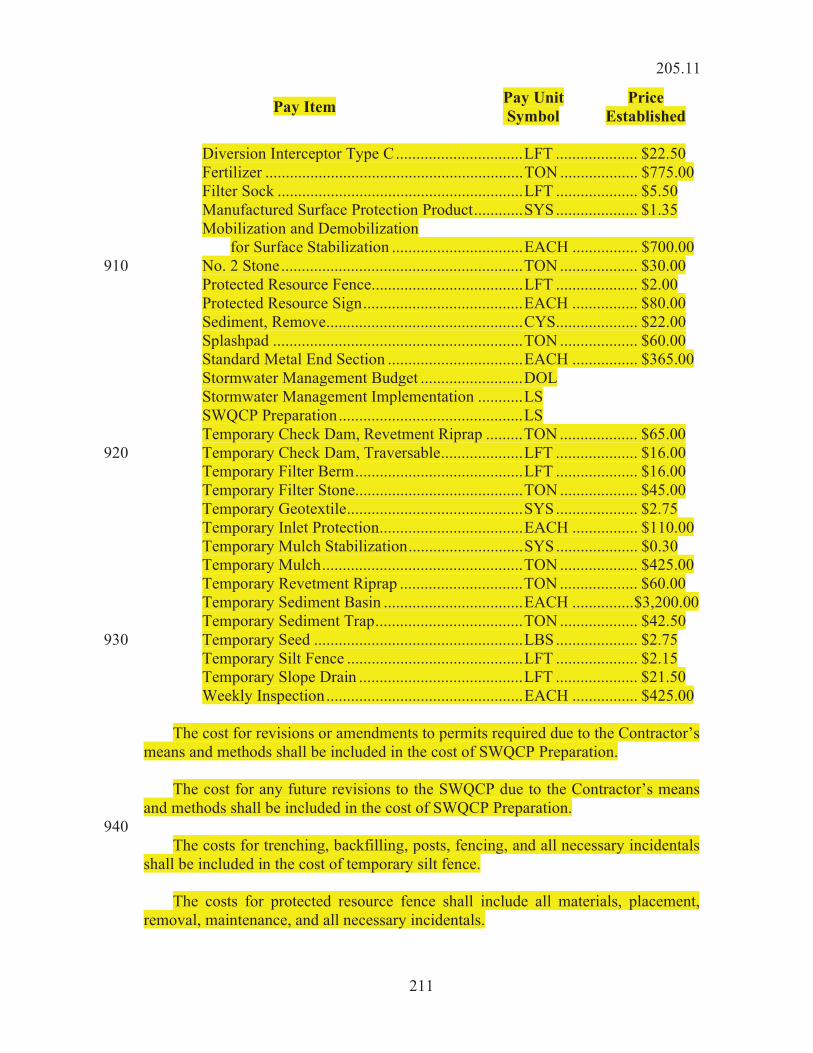
211
Pay Item Pay Unit Symbol
Price Established
Diversion Interceptor Type C ............................... LFT .................... $22.50 Fertilizer ............................................................... TON ................... $775.00 Filter Sock ............................................................ LFT .................... $5.50 Manufactured Surface Protection Product ............ SYS .................... $1.35 Mobilization and Demobilization for Surface Stabilization ................................ EACH ................ $700.00 No. 2 Stone ........................................................... TON ................... $30.00 910 Protected Resource Fence ..................................... LFT .................... $2.00 Protected Resource Sign ....................................... EACH ................ $80.00 Sediment, Remove ................................................ CYS.................... $22.00 Splashpad ............................................................. TON ................... $60.00 Standard Metal End Section ................................. EACH ................ $365.00 Stormwater Management Budget ......................... DOL Stormwater Management Implementation ........... LS SWQCP Preparation ............................................. LS Temporary Check Dam, Revetment Riprap ......... TON ................... $65.00 Temporary Check Dam, Traversable .................... LFT .................... $16.00 920 Temporary Filter Berm ......................................... LFT .................... $16.00 Temporary Filter Stone ......................................... TON ................... $45.00 Temporary Geotextile ........................................... SYS .................... $2.75 Temporary Inlet Protection ................................... EACH ................ $110.00 Temporary Mulch Stabilization ............................ SYS .................... $0.30 Temporary Mulch ................................................. TON ................... $425.00 Temporary Revetment Riprap .............................. TON ................... $60.00 Temporary Sediment Basin .................................. EACH ............... $3,200.00 Temporary Sediment Trap .................................... TON ................... $42.50 Temporary Seed ................................................... LBS .................... $2.75 930 Temporary Silt Fence ........................................... LFT .................... $2.15 Temporary Slope Drain ........................................ LFT .................... $21.50 Weekly Inspection ................................................ EACH ................ $425.00 The cost for revisions or amendments to permits required due to the Contractor’s means and methods shall be included in the cost of SWQCP Preparation. The cost for any future revisions to the SWQCP due to the Contractor’s means and methods shall be included in the cost of SWQCP Preparation. 940 The costs for trenching, backfilling, posts, fencing, and all necessary incidentals shall be included in the cost of temporary silt fence. The costs for protected resource fence shall include all materials, placement, removal, maintenance, and all necessary incidentals.
205.11

212
The costs for protected resource signs shall include all materials, placement, removal, maintenance, and all necessary incidentals. The cost for stakes, trenching, backfilling, posts, and all necessary incidentals 950 shall be included in the cost of temporary check dams, traversable. The payment for temporary sediment basin shall include all costs involved with construction of the basin except for excavation, revetment riprap, and filter stone. The payment for temporary sediment trap shall include all costs involved with construction of the trap except for excavation. Temporary entrances utilized by the Contractor for borrow and waste areas will not be paid for directly. 960 The costs for diversion interceptor types A and B and interceptor ditches shall be included in the cost of other earth moving items. The cost for anchors and all incidentals necessary to perform the work shall be included in the cost of temporary slope drains. The costs of materials, installation, inspection, maintenance, and removal of BMPs at off-site locations designated in 205.03 will not be measured for payment. 970 The payment for BMPs specified herein shall include materials, installation, maintenance, removal and proper disposal. The costs associated with sediment removal due to BMP maintenance shall be included in the cost of sediment removal. The costs associated with the replacement of temporary filter stone due to BMP maintenance will be paid for as temporary filter stone. The costs of constructing, maintaining, and removal of the construction entrance, 980 other than those constructed by the Contractor for borrow and waste sites, shall be included in No. 2 stone. No direct payment will be made for construction entrances for borrow and waste sites. The costs associated with concrete washout will not be paid for directly but shall be included in the costs of other concrete pay items. All costs associated with the weekly and post-event inspections, including inspections required by regulatory agencies, and all other inspections conducted prior to the original contract completion date, shall be included in the cost of Stormwater 990 Management Implementation.
205.11

213
SECTION 206 – STRUCTURE EXCAVATION 206.01 Description This work shall consist of the excavation and backfill or disposal of all materials required for the construction of foundations for substructures of bridges, culverts, and retaining walls. It shall also consist of the furnishing and subsequent removal of all necessary materials and equipment for and the construction of cribs, cofferdams, caissons, and similar items, together with their dewatering. The work shall be in accordance with 105.03. 10 All excavation for structures below the designed slope or subgrade line as shown on the plans shall be included under this item. Unless otherwise specified, structure excavation shall include all pumping, bailing, draining, sheeting, bracing, and incidentals required for proper execution of the work. 206.02 Class X Excavation (a) General Excavation 20 If one or more of the following materials is encountered within the limits of foundation excavating, such shall be defined as class X excavation. 1. solid rock, hard ledge rock, slate, hard shale, or conglomerate,
any of which is actually removed by blasting or use of pneumatic or equivalent tools and which could not reasonably be removed by any other method;
2. loose stones or boulders more than 1/2 cu yd in volume; 30
3. concrete, masonry, or other similar materials which are parts of an old structure not shown on the plans;
4. timber grillages, old foundation piling, buried logs, stumps, or similar materials which extend beyond the limits of excavation so that they must be cut off. Such obstructions shall be removed back to cofferdam limits and the portions so removed within cofferdam limits will be considered as class X.
Material commonly known as hardpan will not be considered as class X. If 40 material is encountered during excavation which seems to be in accordance with that defined herein as class X, notification shall be made in writing, and ample time shall be allowed to make necessary investigations and measurements to determine the class and volume of the material in question.
206.02

214
(b) Excavation for Foundation of Traffic Support Structures If class X material as defined in 206.02(a) is encountered within the limits of foundation excavation for traffic support structures, overhead sign structure foundations, strain pole, or high mast lighting foundations, the foundation shall be located as directed. 50 If class X material in accordance with 206.02(a)1 is encountered at foundations for overhead sign structures, strain poles, signal cantilever structures, high mast lighting poles, and ITS towers, the material shall be excavated to allow the foundation to be embedded as shown on the plans or as directed. If class X material in accordance with 206.02(a)1 is encountered at foundations for wide flange sign supports, signal pedestals, conventional light poles, the material shall be excavated to allow the foundation to be embedded a distance that is equal to 1/2 of the remaining depth of the foundation before the material was encountered or 60 to a minimum 3 ft depth, whichever is greater. If class X material in accordance with 206.02(a)2, 206.02(a)3, or 206.02(a)4 is encountered, the material shall be removed to the total depth of the foundation as shown on the plans. 206.03 Wet Excavation Wet excavation shall be defined as that portion of foundation excavation, except class X, which is below a horizontal plane designated on the plans as the upper limit of wet excavation and above the bottom of the footing as shown on the plans. If wet 70 excavation is a pay quantity and the elevation of the upper limit of wet excavation is not shown on the plans, an elevation of 1 ft above the elevation of low water level as shown on the plans shall be used as such limit. 206.04 Dry Excavation Dry excavation shall be defined as that portion of foundation excavation, except class X, which is above the upper limit of wet excavation. 206.05 Foundation Excavation, Unclassified If the Schedule of Pay Items provides a pay quantity of foundation excavation, 80 unclassified, and none for wet excavation or dry excavation, then foundation excavation, unclassified shall include all work described as wet excavation and dry excavation, regardless of whether or not water is encountered, but shall not include class X. Even though designated herein as foundation excavation, unclassified, it shall be regarded in these specifications as a class of excavation. If no upper limit of foundation excavation, unclassified is shown on the plans, it shall be at the original ground except where waterway excavation, common excavation, or other classified excavation overlaps the area of foundation excavation and is a pay item. The upper limit of foundation excavation, unclassified shall be the 90 lower limit of the overlapping classified material.
206.03

215
CONSTRUCTION REQUIREMENTS
206.06 General Requirements The drainage requirements of 203.14 shall apply to excavation for structures and, in addition, adequate outlets shall be provided as shown on the plans or as directed, if within the limits of the excavation. All excavation shall be adequately shored to avoid damage to the structure, its 100 approaches, adjacent roadway, embankments, tracks, buildings, or other property. Footing excavation shall, in general, conform with the outlines of footings as shown on the plans, or as revised, and shall be of sufficient size to enable construction of the footings to their full required dimensions. If an existing structure is being extended, the old footings shall be adequately protected. Boulders, logs, or other unforeseen obstacles encountered shall be removed. The elevations of bottoms of footings as shown on the plans shall be considered approximate. The final elevations shall depend on conditions encountered during 110 excavation, at which time other elevations may be ordered in writing if necessary to secure satisfactory foundations. Where existing foundation material would not support the contemplated load safely, the plans may require, or it may be directed that foundation piles be driven in the footing area. This piling shall be furnished, driven, and paid for in accordance with 701. 206.07 Disposal of Excavated Material Except as otherwise herein provided, material excavated for a structure or its 120 approaches, including any material excavated beyond the pay limits of foundation excavation or its specified or approved extensions, shall, if suitable, be used for filling around the new structure, for spandrel filling, approach embankment, regular embankment, or for any combination of these, all as specified or directed. If excavated material, in accordance with 211.02, is required at the structure or in its approaches, then this material shall be used as special fill and placed in accordance with the applicable provisions of 211. Surplus or unsuitable material shall not be disposed of in any manner that would 130 obstruct or pollute the stream or otherwise impair the efficiency or appearance of the structure. If there are piers in the water, permission may be granted to waste excavated material adjacent to these piers provided such waste does not obstruct the waterway. If usable excavated material is wasted without authority, the quantity so wasted will be deducted from the quantities of common excavation, borrow, or B borrow, depending on the nature of the waste and its use.
206.07

216
Disposal of surplus or unsuitable material, including class X excavation, outside the right-of-way shall be in accordance with 201.03 and 203.08. 140 206.08 Preparation of Foundation Surfaces Excavation for foundations on rock without piles shall extend a minimum of 2 ft into solid rock. All rock or other hard material, if to be left in place as a foundation surface, shall be freed of loose material, cleaned, and cut to a firm surface. The final surface shall be level, stepped, or serrated as directed. Seams shall be cleaned and filled with concrete, cement mortar, or grout. These conditions shall prevail when the foundation masonry is placed. Where the masonry is to rest on a foundation surface other than those described above, the approximate bottom of the excavation shall not be disturbed. The final 150 removal of material to the required grade shall be done carefully just prior to placing the foundation masonry. The final surface shall be left smooth and, unless otherwise designated, be level. Notification shall be given after final excavation of each foundation is completed. No masonry shall be placed until the depth of the excavation and the character of the foundation material have been approved. Rock at the bottom of spread footings shall be proof-tested. For state-administered contracts, the Department’s Geotechnical Engineering Division shall be contacted 160 prior to proof-testing. For local public agency contracts, the Engineer shall be contacted prior to proof-testing. Proof-testing with a small diameter test hole of a minimum 2 in. inside diameter shall be drilled into the foundation base using rotary or percussive drilling methods. Holes shall be drilled into sound rock to a depth of 5 ft or as directed. Three holes shall be drilled into each foundation base. Observations shall be made at each hole as follows: 1. speed of drilling 2. drill pressure 170 3. dropping or clogging of drill bit 4. loss of drill water, if used 5. probing of the sides of the holes with a right angled chisel point.
The chisel shall be formed from a rod of 3/8 or 1/2 in. diameter 6. continuity of bearing material 7. rock quality designation in accordance with ASTM D6032 180 8. photos shall be taken of the rock core and the sidewall of the
borehole from which core has been extracted.
206.08

217
A professional engineer shall supervise the proof testing work. A report for each hole shall be prepared and submitted to the Engineer for review and approval. 206.09 Cofferdams and Temporary Construction Dikes Working drawings shall be submitted in accordance with 105.02. They shall show the proposed method of cofferdam construction and other details left open to choice 190 or not fully shown on the plans. Working drawings for dikes to be used in lieu of cofferdams or to be used for access to the work shall be submitted in accordance with 105.02, if such dikes are to be constructed within the waterway. Approval of such drawings will only be given if the probability of stream pollution and stream flow restriction is minimal. Cofferdams shall be constructed for all abutments and piers where water or unstable soil is encountered or where the soil may become unstable; excessive stream pollution or stream flow restriction might occur with other construction procedures; or 200 if necessary to support the sides of excavated areas, embankment, adjacent buildings, tracks, or other premises. In general, they shall be carried down well below bottoms of footings, shall be well braced, and as nearly watertight as practicable. The interior dimensions shall be sufficient to provide ample clearance to enable pile driving, the construction of forms, and clearance for pumping equipment outside the forms. Cofferdams shall be constructed to protect plastic concrete against damage from a sudden rising of the stream and to prevent damage to the foundation by erosion. No timber or bracing that would extend into substructure masonry shall be left in cofferdams except with written permission. 210 Cofferdams which become tilted or moved laterally during the process of sinking shall be righted or enlarged to provide ample clearance. Any necessary correction shall be made with no additional payment. Except as otherwise provided herein, cofferdams shall be dewatered and sediment controlled in accordance with 108.04. Pumping will not be allowed for 24 h after concrete placement, unless otherwise approved. When conditions are encountered under which it is established that no reasonable 220 pumping will dewater the cofferdam when every practicable effort has been made to reduce the inflow of water, or other conditions are such that a foundation seal is necessary, the construction of a concrete foundation seal may be required of such dimensions as necessary. This seal shall be constructed in accordance with 702.20(f). Unless otherwise specified, all cofferdam bracing shall be removed and all sheeting removed or cut off at least 2 ft below the finished ground line, except within the low-water channel it may either be removed or cut off even with the stream bed. Removal shall be such that the finished masonry will not be marred or disturbed. 230
206.09

218
206.10 Method of Measurement Structure excavation, except wet excavation, will be measured in cubic yards in its original position below the limits of roadway excavation. Wet excavation will be the theoretical quantity in accordance with 206.11(b). When structures are to be placed in embankment sections, the natural ground line, as cross sectioned, will be the uppermost level of computation unless otherwise specified or shown on the plans. Class X material encountered and removed during the excavation of foundations for traffic support structures will be measured to the foundation neat lines as shown on the plans below the surface of class X material. 240 If the pay unit for any item of excavation in the Schedule of Pay Items is lump sum, no measurement will be made. Extended excavation for footings will be measured to include the entire depth needed for the deeper footing and the entire width needed to comply with OSHA or IOSHA requirements. 206.11 Basis of Payment The accepted quantities of structure excavation will be paid for at the contract unit 250 price per cubic yard or lump sum. Unless otherwise provided, excavation for bridges will be paid for at the contract unit price or prices per cubic yard for the respective class or classes involved. If cofferdams are specified as a pay item, they will be paid for at the contract lump sum price for cofferdams. If a foundation seal is constructed, it will be paid for in accordance with 702.28. 260 The quantity of class X excavation to be paid for will be the cubic yards of such material actually removed from within vertical planes defining the neat lines of the footings, except where material classified as class X excavation overlays other material which shall be excavated to cofferdam limits. Such overlying strata will be paid for to the limits of the material excavated beneath it. Unless otherwise provided, no additional payment will be made for such excavation made outside these limits. If class X excavation is encountered and there is no contract unit price for class X excavation, payment will be made at a unit price per cubic yard as follows: 270 1. $1,000.00 per cu yd if the quantity of class X excavation is less
than or equal to 1 cu yd per foundation.
2. When the quantity of class X excavation is greater than 1 cu yd per foundation, payment will be made at $1,000.00 per cu yd for the quantity up to 1 cu yd. The quantity in excess of 1 cu yd, payment will be made at $125.00 per cu yd.
206.10

219
Except as otherwise provided, the quantity of dry excavation to be paid for will be the amount of such excavation actually removed from its original position within 280 vertical planes which are 18 in. outside the neat lines of the footings and parallel thereto. Regardless of the quantity actually removed, the quantity of wet excavation to be paid for will be the theoretical volume bounded by the bottom of the footings, the upper limit of wet excavation, and vertical planes which are 18 in. outside the neat lines of footings and parallel thereto. Additional payment will not be made for such excavation outside these limits. Where it is necessary to carry a footing or a portion of a footing deeper than its elevation shown on the plans, such additional excavation, except a portion thereof classified as class X which is carried down to a plane which is 4 ft below the bottom 290 of footing as shown on the plans, will be paid for as extended dry excavation, extended wet excavation, or extended foundation excavation unclassified, at a price to be determined by multiplying the contract unit price for dry excavation, wet excavation, or foundation excavation, unclassified, respectively by the factors shown below. 1. For footings or portions thereof lowered not more than 1 ft, the
factor will be 2.0.
2. For footings or portions thereof lowered more than 1 ft and not more than 2 ft, the factor will be 2.5. 300
3. For footings or portions thereof lowered more than 2 ft and not more than 3 ft, the factor will be 3.5.
4. For footings or portions thereof lowered more than 3 ft and not more than 4 ft, the factor will be 5.0.
For a footing lowered more than 4 ft below its elevation shown on the plans, all such extended excavation below the bottom of footing elevation shown on the plans to the revised bottom of footing shall be done as extra work in accordance with 104.03. 310 Payment will be made in accordance with 109.05. All backfill material or sub-footing material required whose source is other than structure excavation will be paid for at the contract unit price for the material being used or as extra work if no unit price has been established. A change order will be prepared in accordance with 109.05. The cost of furnishing all materials and labor associated with proof testing of rock shall be included in the cost of other pay items. 320 If a borrow area is required and borrow is not specified as a pay item, payment will be made in accordance with 203.28.
206.11

220
If a waste area is required and the contract documents do not identify excess excavation or require removal of any items, payment will be made in accordance with 203.28. Except for sign foundations, traffic signal foundations, and highway illumination foundations, if a type of excavation for which no pay item exists is required and the new type of excavation requires the Contractor to use equipment not otherwise being 330 used on the contract, payment will be in accordance with 203.28. If a type of excavation for which no pay item exists is required and the new type of excavation requires additional traffic control not shown on the plans or results in traffic control being required for an additional period of time, payment will be made in accordance with 203.28. Payment will be made under: Pay Item Pay Unit Symbol 340 Cofferdam .................................................................................. LS Excavation, Dry ......................................................................... CYS Excavation, Foundation, Unclassified ....................................... CYS Excavation, Wet ........................................................................ CYS Excavation, X ............................................................................ CYS The cost of placing and compacting of all backfill when the materials used are obtained from excavation, clearing and grubbing required and not paid for under another pay item, formation of embankments made with material from structure 350 excavation, and disposal of all surplus or unsuitable excavation, unless otherwise specified shall be included in the cost of the pay items. The cost for disposing of surplus or unsuitable excavated materials outside the right-of-way shall be included in the various pay items in this section. (a) Culverts This requirement will not include pipe culverts. Excavation for culverts will not be paid for directly. The cost thereof shall be included in the cost of the structure or structure extension. The cost of all necessary removal and satisfactory disposal of all 360 or part of the existing old structure unless its removal is otherwise provided for, cleaning out an old channel or constructing a new channel within the right-of-way limits and widening it to the grade of the existing or proposed new stream bed as shown on the plans or as directed, construction of all necessary curbs and cofferdams and their subsequent removal, subsoil borings or soundings below bottom of footings, dewatering, disposal of excavated materials, and all labor, equipment, tools, and necessary incidentals shall be included in the cost of this work. If a culvert is lowered or relocated at the direction of the Engineer, or material of
206.11

221
such nature is encountered so that additional excavation is necessary, the additional 370 excavation will not be paid for if it is 10 cu yds or less. Additional excavation in excess of 10 cu yds will be paid for at $125.00 per cu yd. If the additional excavation in excess of 10 cu yds is identified as class X excavation, and there is no pay item for class X excavation, the additional work will be paid for at $125.00 per cu yd for the quantity in excess of 10 cu yds, regardless of the depth the culvert is lowered. (b) Bridges The cost of clearing right-of-way within the project limits; constructing, dewatering, and removal of cofferdams, if not a pay item; subsoil borings or soundings below bottoms of footings; final preparation of foundation surfaces; disposal of 380 excavated material; and all labor, equipment, tools, and incidentals necessary to the satisfactory completion of the excavation shall be included in the cost of this work. The cost of all required working drawings; furnishing, hauling, and placing necessary materials; construction; maintenance; dewatering; removal of bracing; removal of or cutting off the sheeting; and labor, equipment, tools, and necessary incidentals shall be included in the cost of cofferdams. If cofferdams are not specified as a pay item, and if cofferdams are necessary, their cost shall be included in the cost of excavation or the concrete requiring their use. 390 If there is no pay item for dry excavation, the cost of this part of the work shall be included in the cost of the foundation concrete or for other concrete requiring such excavation. However, where waterway excavation, common excavation, or other classified excavation overlaps the area of dry foundation excavation, no deduction will be made in the pay volume of such overlapping classified material. This exception will apply only if dry excavation is not a pay item. Except as otherwise provided in 206.05, the cost of foundation excavation unclassified shall include all work and elements of volume, and excavation described 400 above for wet excavation and dry excavation, regardless of whether or not water is encountered. The cost of foundation excavation unclassified shall not include the cost of class X excavation. The classifications for necessary excavation for a cantilevered wing outside the limits of foundation excavation shall be the same as those governing the excavation inside such limits. The quantity to be paid for will be that actually removed from its original position within vertical planes 18 in. outside the neat lines shown on the plans and parallel thereto and above a plane 1 ft below and parallel to the bottom surface of the wing. 410 The classifications for necessary excavation for arch superstructures outside the limits of foundation excavation or waterway excavation shall be those governing the excavation inside the limits of foundation excavation or waterway excavation, depending on the location of the excavation for the arch superstructure. Such
206.11

222
excavation shall be bounded by vertical planes which are 1 ft outside the outside faces of the arch ring and parallel thereto, by a vertical plane passing through the intersection of the intrados of the arch ring and the original ground line and parallel to the face of the abutment, and the vertical plane bounding the foundation excavation on the side adjacent to the arch ring. The lower limit shall be a sloping plane which is 1 ft below 420 a plane connecting the intersection of the intrados of the arch ring and the original ground, and the intersection of the intrados of the arch ring with the vertical plane bounding the foundation excavation. For U-abutments, the limits of dry excavation to be paid for will be extended to include all material removed from between the limits of the wing excavation and above the elevation of the bottom of the lowest tie beam. If the bottom of the lowest tie beam is below the upper limits of wet excavation, the limits of wet excavation and dry excavation to be paid for will be extended to include material actually and necessarily removed from between the limits of the wing excavation. 430 Where it is necessary to excavate outside the foundation excavation limits for superstructure or extensions other than those described above, the pay limits will be extended to include all such excavation, as determined necessary. If a suitable sump is constructed outside the pay limits as described above, such limits will be extended to include the actual lines of the sump. The additional pay limits added for the sump will not exceed 4% of the area of the footing involved. (c) Traffic Structure Supports 440 The cost of excavation for traffic structure supports, except for class X material in accordance with 206.02(a)1, shall be included in the cost of the foundation material.
SECTION 207 – SUBGRADE 207.01 Description This work shall consist of the construction of the subgrade in accordance with 105.03.
MATERIALS 207.02 Materials Materials shall be in accordance with the following: 10 Chemical Modifiers ............................................................ 215.02 Coarse Aggregate, Class D or Higher, Size No. 5, 8, 43, 53, or 73 .......................................... 904.03 Geogrid, Type IB ................................................................ 918.05 Geocell Confinement System ............................................. 214 Geotextile for Pavement and Subgrade .............................. 918.02(c) Water .................................................................................. 913.01
207.01

223
Air-cooled blast furnace slag shall not be used for subgrade treatment Types ID, 20 IV, and IVA.
Soil Property Test Method Requirements Dry Weight Organic Material AASHTO T 267 3% Max Dry Density AASHTO T 99 > 100 pcf Liquid Limit AASHTO T 89 50 Soluble Sulfate ITM 510 1000 ppm Note: Only soils meeting these requirements will be allowed within the specified thickness of the subgrade treatment in cut sections. Only soils meeting these requirements will be allowed within 24 in. of the finished subgrade elevation in fill sections.
CONSTRUCTION REQUIREMENTS
207.03 Construction Requirements (a) Subgrade Construction Methods The subgrade shall be constructed uniformly transversely across the width of the pavement including shoulders or curbs unless shown otherwise on the plans, by one 30 of the following methods: 1. chemical modification in accordance with 215; 2. aggregate No. 53 in accordance with 301; 3. geogrid in accordance with 214 placed under aggregate No. 53
in accordance with 301, or 4. soil compaction to 100% of maximum dry density; 40 5. geotextile in accordance with 214 placed under aggregate No.
5, 8, and 53 in accordance with 301. Longitudinally, the treatment may vary depending on the method of construction. (b) General Requirements All rock greater than 3 in. shall be removed or broken off and placed at least 6 in. below the specified subgrade. Holes or depressions resulting from the removal of unsuitable material shall be filled with soils in accordance with 207.02 or B borrow 50 and compacted in accordance with 203.23. Coal within the specified thickness of the subgrade shall be excavated if directed,
207.03
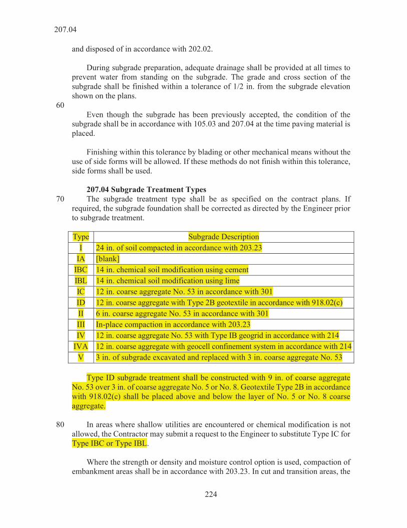
224
and disposed of in accordance with 202.02. During subgrade preparation, adequate drainage shall be provided at all times to prevent water from standing on the subgrade. The grade and cross section of the subgrade shall be finished within a tolerance of 1/2 in. from the subgrade elevation shown on the plans. 60 Even though the subgrade has been previously accepted, the condition of the subgrade shall be in accordance with 105.03 and 207.04 at the time paving material is placed. Finishing within this tolerance by blading or other mechanical means without the use of side forms will be allowed. If these methods do not finish within this tolerance, side forms shall be used. 207.04 Subgrade Treatment Types The subgrade treatment type shall be as specified on the contract plans. If 70 required, the subgrade foundation shall be corrected as directed by the Engineer prior to subgrade treatment. Type Subgrade Description
I 24 in. of soil compacted in accordance with 203.23 IA [blank]
IBC 14 in. chemical soil modification using cement IBL 14 in. chemical soil modification using lime IC 12 in. coarse aggregate No. 53 in accordance with 301 ID 12 in. coarse aggregate with Type 2B geotextile in accordance with 918.02(c) II 6 in. coarse aggregate No. 53 in accordance with 301 III In-place compaction in accordance with 203.23 IV 12 in. coarse aggregate No. 53 with Type IB geogrid in accordance with 214
IVA 12 in. coarse aggregate with geocell confinement system in accordance with 214 V 3 in. of subgrade excavated and replaced with 3 in. coarse aggregate No. 53
Type ID subgrade treatment shall be constructed with 9 in. of coarse aggregate No. 53 over 3 in. of coarse aggregate No. 5 or No. 8. Geotextile Type 2B in accordance with 918.02(c) shall be placed above and below the layer of No. 5 or No. 8 coarse aggregate. In areas where shallow utilities are encountered or chemical modification is not 80 allowed, the Contractor may submit a request to the Engineer to substitute Type IC for Type IBC or Type IBL. Where the strength or density and moisture control option is used, compaction of embankment areas shall be in accordance with 203.23. In cut and transition areas, the
207.04

225
top lifts shall be removed, and the bottom 6 in. compacted in-place in accordance with 203.23. The excavated material shall then be replaced and compacted in 6 in. lifts in accordance with 203.23. Removal of the lifts may be waived and only the upper 6 in. compacted in accordance with 203.23 when it is determined, through testing in accordance with 203.24, that the lower lifts comply with 203.23. 90 In sections where rock, shale, sandstone or its mixtures are encountered, these materials shall be undercut 24 in. below the subgrade elevation and replaced with coarse aggregate No. 53 or No. 73 and compacted in accordance with 301.06. Geotextiles used shall be in accordance with 918.02. All irregularities and holes shall be graded with either coarse aggregate No. 53 or No. 73. If an aggregate base is part of the HMA pavement structure, the 24 in. excavation depth shall be reduced by the thickness of the aggregate base. The 3 in. compacted aggregate as part of the subgrade treatment Type V shall be 100 compacted to 100% prior to the placement of the pavement. When conditions are encountered below the specified subgrade treatment depth that prevent achieving the specified subgrade compaction, such conditions shall be corrected in accordance with 203.09, or as directed. Proofrolling shall be performed in accordance with 203.26. 207.05 Method of Measurement Subgrade treatment will be measured in both cut and fill areas by the square yard 110 per type. Chemicals for soil modification using cement or lime, excavation, aggregates, geotextile, and geogrid materials will not be measured. The undercutting of rock, where encountered, will be measured in accordance with 203.27(b). 207.06 Basis of Payment The accepted quantities of subgrade treatment will be paid for at the contract unit price per square yard per type, complete in place. In areas where shallow utilities are encountered or the Contractor elects to use Type IC for Type IBC or Type IBL, 120 payment will be made at the price of Type IBC or Type IBL. The undercutting of rock, where encountered, will be paid for in accordance with 203.28. Payment will be made under: Pay Item Pay Unit Symbol Subgrade Treatment, Type _____ ............................................. SYS 130
207.06

226
The cost of subgrade treatments including testing, sampling, aggregates, chemicals for soil modification with cement or lime, geogrid, geotextile and geocell confinement system, coarse aggregate for subgrade Type IC, Type ID, Type II, Type IV, Type IVA, Type V, water, and the excavation required, shall be included in the cost of the pay item. The cost of excavation and grading of existing railroad ballast and railroad bed material shall be included in the cost of subgrade treatment, Type V. 140 Where conditions exist below the specified subgrade compaction depth that prevent achieving the specified compaction, payment for correcting such conditions will be made based on the directed method of treatment.
SECTION 208 – FINISHING SHOULDERS, DITCHES, AND SLOPES 208.01 Description This work shall consist of the final shaping and dressing of shoulders, ditches, and slopes by hand or machine methods, or both, to the required smoothness in accordance with these specifications and in reasonably close conformance with the elevations and cross sections shown on the plans or as directed. Where divided pavement is constructed, each roadway with its shoulders, ditches, and slopes will be considered a separate roadway. 10
CONSTRUCTION REQUIREMENTS 208.02 Finishing Shoulders Unless otherwise provided, shoulders shall be constructed of earth or other approved material which contains no sod, weeds, sticks, roots, or other perishable matter. The inside edges shall be built up slightly above the finished surface of the adjoining pavement and compacted thoroughly with a roller weighing no less than 5 t and with the roller wheel slightly overlapping the pavement. Rolling shall continue until there is no break between the pavement and shoulders, and until the required 20 cross section is obtained. If rolling is not practicable on shoulders for approach pavement or other miscellaneous areas, compaction shall be obtained with mechanical tamps, vibrators, or other satisfactory means. Except where permission has been granted to widen shoulders to dispose of surplus excavation, the outside edges shall be parallel to the pavement edges. Where cuts are widened beyond the typical cross sections shown on the plans in 30 order to obtain additional material for constructing shoulder widths required or where fills are widened to dispose of excess excavated material, the shoulders shall be finished to the widths as finally constructed.
208.01

227
It may be necessary to finish shoulders after the pavement is opened to traffic. As a matter of safety to traffic, the pavement shall be kept as free as possible from shoulder material and equipment. The adjacent pavement over which traffic is being routed shall be cleaned at the close of each work day. 208.03 Finishing Ditches 40 Ditches shall be finished to the lines and grades shown on the plans or as otherwise laid out. The edges shall be parallel to the pavement unless it is necessary to have the gradients different from that of the pavement in order to obtain proper drainage, in which case the edges shall be as determined. 208.04 Finishing Slopes All cut and fill slopes shall be constructed to the cross sections shown on the plans or to revised sections where cuts are widened to obtain additional material or fills widened to utilize excess. Cut and fill slopes shall be finished to the degree ordinarily obtained by a blade grader, scraper, or hand shovel. 50 208.05 Blank 208.06 Finishing at Contract Drainage Structures If the contract work is for bridges or culverts or for extensions thereof, the requirements of this specification shall apply to the right-of-way within the contract structure limits, unless otherwise specified. 208.07 Method of Measurement Finishing will not be measured for payment unless otherwise provided. 60 208.08 Basis of Payment Finishing shoulders, ditches, and slopes will not be paid for directly. The cost thereof shall be included in the cost of other pay items.
SECTION 209 – FINISHING EARTH GRADED ROADS 209.01 Description This work shall consist of leveling, shaping, and otherwise completing an earth graded road ready for acceptance when the contract is for grading or for grading and structures, but not when the contract includes paving or surfacing. 209.02 Construction Requirements After all grading is substantially complete and structures, if any, are finished, the roadbed and cut and fill slopes shall be shaped properly and, where necessary, 10 compacted. Shaping and compacting shall be with approved equipment supplemented with
209.02
228
hand methods if necessary. Reasonably smooth surfaces shall be obtained and finished at least to within ± 0.1 ft of the required profile and cross sections shown on the plans or as directed. All rock greater than 6 in. encountered shall be removed or broken off at least 6 in. below the subgrade surface. Holes or depressions resulting from the removal of unsuitable material shall be filled with an acceptable material and compacted to 20 conform with the surrounding subgrade. Final trimming and cleaning shall be in accordance with 210. 209.03 Method of Measurement Finishing earth graded roads will not be measured for payment unless otherwise provided. 209.04 Basis of Payment Finishing earth graded roads will not be paid for directly. The cost thereof shall 30 be included in the cost of other pay items.
SECTION 210 – FINAL TRIMMING AND CLEANING 210.01 Description This work shall consist of trimming and cleaning the otherwise completed highway between right-of-way lines for its entire contract length. 210.02 Construction Requirements At the time of acceptance, the following conditions shall prevail for the entire contract length and also for the full right-of-way width except as hereinafter provided. 10 Debris and rubbish shall be removed and disposed of in accordance with 201.03. Remaining loose stones and broken masonry meeting the aggregate requirements for hand laid or grouted riprap shall be stored in neat piles on the right-of-way as directed. Weeds, brush, and stumps shall be cut close to the ground. Disposal shall be in accordance with 201.03 and 203.08. Cut and fill slopes made or disturbed shall be left reasonably smooth and uniform. 20 Loose and overhanging rock shall be removed. Floors, roadways, railings, bottom chords, shoes, and seats of bridges shall be cleaned of rubbish, sand, stone, gravel, and dirt. Waterways shall be left unobstructed. Culverts and other drainage structures shall be left clean for their entire length.
209.03

229
If the contract is for construction of a new pavement or for grading and structures only on a right-of-way acquired for divided highway construction, one roadway of which has been constructed and on which the Department has assumed normal maintenance, the provisions of this specification shall not apply to the maintained 30 portion except to those areas of such which are disturbed by the operations. If the contract is for construction of a portion of a divided highway on a right-of-way on which no previous construction has been done or on a divided highway right-of-way on which a previous grading-only contract has been completed, then the provisions of this specification shall apply to the entire right-of-way for the full contract length. Unless otherwise set out in the special provisions for a contract which includes work for patching, widening, resurfacing, surface treating, undersealing, or for a 40 combination of these, or for a contract through which traffic is being maintained during construction, these requirements will apply only to that portion of the right-of-way disturbed by the operations. 210.03 Method of Measurement Final trimming and cleaning will not be measured for payment unless otherwise provided. 210.04 Basis of Payment Final trimming and cleaning will not be paid for directly. The cost thereof shall 50 be included in the cost of other pay items.
SECTION 211 – B BORROW AND STRUCTURE BACKFILL 211.01 Description This work shall consist of backfilling excavated or displaced peat deposits; filling up to designated elevations of spaces excavated for structures and not occupied by permanent work; constructing bridge approach embankment; and filling over structures and over arches between spandrel walls, all with special material.
MATERIALS 10 211.02 Materials Materials shall be in accordance with the following: B Borrow ............................................................................ As Defined* Flowable Backfill ............................................................... 213 Geotextile ........................................................................... 918.02 Structure Backfill ............................................................... 904.05 * The material used for special filling shall be of acceptable quality,
free from large or frozen lumps, wood, or other extraneous matter and shall be known as B borrow. It shall consist of suitable sand, 20
211.02

230
gravel, crushed stone, ACBF, GBF, or other approved material. The material shall contain no more than 10% passing the No. 200 (75 μm) sieve and shall be otherwise suitably graded. The use of an essentially one-size material will not be allowed unless approved.
Aggregate for end bent backfill shall be No. 8 or No. 9 crushed stone or ACBF, class D or higher. The Contractor has the option of either providing B borrow or structure backfill 30 from an established CAPP source, or supplying the material from another source. The Contractor has the following options for supplying B borrow or structure backfill from a local site: (a) the establishment of a CAPP Producer Yard at the local site in
accordance with 917; or (b) use a CAPP Certified Aggregate Technician or a consultant on the
list of Qualified Geotechnical Consultants For Gradation Control Testing. 40
For material excavated within the project limits, gradation control testing will be performed by the Department if the Contractor is directed to use the material as B borrow or as structure backfill. The frequency of gradation control testing shall be one test per 2,000 t based on production samples into a stockpile or by over the scales measurement, with a minimum of two tests per contract, one in the beginning and one near the mid-point. The sampling and testing of these materials shall be in accordance with applicable requirements of 904 for fine and coarse aggregates. The Contractor shall notify the 50 Engineer in writing of the plan to measure the material.
CONSTRUCTION REQUIREMENTS 211.03 General Requirements If B borrow or structure backfill is obtained from borrow areas, the locations, depths, drainage, and final finish shall be in accordance with 203. Unless otherwise specified, if excavated material complies with 211.02 and if B borrow or structure backfill is required for special filling, the excavated material 60 shall be used as such. If there is a surplus of this material, such surplus shall be used in embankment. The provisions of 203.19 shall apply to placing this material at structures. All surplus in excess of the directed or specified use on the right-of-way shall be disposed of in accordance with 201.03. If fill or backfill as described in this specification is within embankment limits, and if it is not required that the entire fill or backfill be of B borrow and placed as such,
211.03

231
then that portion above the free-water level shall be placed in accordance with applicable provisions of 203 and compacted to the required density. 70 If borrow is required outside the specified limits of B borrow, material in accordance with the specifications for B borrow may be furnished at the contract unit price for borrow; however, the quantity of borrow measured for payment outside the limits of structure backfill will not exceed the theoretical quantity of B borrow furnished. Unless otherwise specified, all spaces excavated for and not occupied by bridge abutments and piers, if within embankment limits, shall be backfilled to the original ground line with B borrow, and placed in accordance with 211.04. 80 Where B borrow or structure backfill is required as backfill at culverts, retaining walls, sewers, manholes, catch basins, and other miscellaneous structures, it shall be compacted in accordance with 211.04. Where specified, aggregate for end bent backfill shall be placed behind end bents and compacted in accordance with 211.04. Prior to placing the aggregate, a geotextile shall be installed in accordance with 616.11. 211.03.1 Structure Backfill Types The structure backfill type shall be as specified. 90 Within each of the following structure backfill types, the Contractor shall choose from the listed options for each type: (a) Type 1
1. Structure backfill in accordance with 904.05.
2. Non-removable or removable flowable backfill in accordance with 213. 100
(b) Type 2
1. Crushed stone aggregate or ACBF structure backfill in accordance with 904.05, except No. 30, No. 4, and 2 in. nominal size aggregate shall not be used.
2. Non-removable or removable flowable backfill in accordance with 213.
110 (c) Type 3 Structure backfill in accordance with 904.05, except only nominal size aggregates 1 in., 1/2 in., No. 4 or No. 30, and coarse aggregate No. 5, No. 8, No. 9, No. 11, or No. 12 shall be used. If ACBF is used, it shall only be used in sizes that meet the size
211.03.1

232
requirements for coarse aggregate No. 5 or No. 8. A type A certification in accordance with 916 shall be provided for the additional structure backfill. The results of the following shall be shown on the certification.
Property Criteria Test Method pH (Note 1) 5 < pH < 10 AASHTO T 289 Organic Content (Note 2) 1% max. AASHTO T 267 Permeability, min. (Note 3) 30 ft/day AASHTO T 215 Notes: 1. One PH test is required for each bench of stone, each source of air-
cooled blast furnace slag, and each source of gravel. 2. One organic content test is required for each source of gravel. 3. One permeability test is required for the smallest aggregate size from
each source. Sizes No. 5, No. 8, and No. 9 do not require a permeability test.
120 The gradation shall be performed on the material used in the permeability test. Testing for permeability shall be performed on the sample of the material compacted to 95% in accordance with AASHTO T 99, Method C or D. All of the tests listed above shall be performed a minimum of once every 12 months per source. In addition to the criteria above, structure backfill for retaining wall systems containing metal components in contact with structure backfill shall also be in accordance with the following criteria:
Property Criteria Test Method Chlorides < 100 ppm AASHTO T 291 Sulfates < 200 ppm AASHTO T 290 Resistivity, min. 3, -cm AASHTO T 288 Internal friction angle, , min. 34° AASHTO T 236* or T 297* * under consolidated drained conditions
130 If the minimum resistivity exceeds 5, -cm, the requirement for the testing of chlorides and sulfates will be waived. The resistivity shall be tested at 100% saturation. All of the tests listed above shall be run a minimum of once every 12 months per source. The Department’s Division of Materials and Tests will evaluate the material from each source and determine the appropriate tests to be performed. Tin accordance with AASHTO T 99, Method C or D. Testing for not be required when using coarse aggregate No. 5, No. 8, or No. 9. 140 (d) Type 4 Removable flowable backfill in accordance with 213.
211.03.1
233
(e) Type 5 Non-removable flowable backfill in accordance with 213. 211.04 Compaction B borrow and structure backfill types 1, 2, and 3 shall be compacted with mechanical tamps or vibrators in accordance with the applicable provisions of 203.23 except as otherwise set out herein. 150 Aggregate for end bent backfill and coarse aggregate used for structure backfill shall be deposited in layers not to exceed 12 in. loose measurement. Each layer shall be mechanically compacted with a compactor having a plate width of 17 in. or larger that delivers 3,000 to 9,000 lb per blow. Each lift shall be compacted with two passes of the compactor. 211.05 Embankment for Bridges When special filling is required, the embankment for bridges shall be constructed using B borrow within the specified limits shown on the plans. All embankment 160 construction details specifically set out in this specification for embankment for bridges shall be considered in accordance with the applicable requirements of 203. At the time B borrow is being placed for approach embankment, a well compacted watertight dam shall be constructed in level lifts, the details of which are shown on the plans. Except as hereinafter specified for material to be used in constructing the enclosing dam, and for growing vegetation, and unless otherwise provided, the material for constructing bridge approach embankment shall be B borrow compacted by mechanical methods. 170 If approach embankment or shoulders are constructed of material not suitable for growing seed or sod, and if one or both of these is required, then such areas shall, unless otherwise specified, be covered with a layer of clay, loam, or other approved material. This layer shall be approximately 1 ft thick after being compacted into place. 211.06 B Borrow Around Bents When specified, B borrow shall be placed around all bents falling within the limits of the approach grade as shown on the plans. Before placing, the surface of the ground on which it is to be placed shall be scarified or plowed as directed. The embankment slope shall be 2:1 on the sides and beneath the structure, and shall be 6:1 from the end 180 of the bridge down to the average ground line, or it may be required to complete the approaches back to the existing grade. An enclosing dam and provisions for growing vegetation shall be constructed in accordance with 211.05. 211.07 Blank 211.08 Spandrel Filling Unless otherwise specified, spandrel fills for arch structures shall be composed of
211.08

234
B borrow. The fill shall be carried up symmetrically in lifts from haunch to crown and simultaneously over all piers, abutments, and arch rings. Compaction shall be in 190 accordance with 211.04. 211.09 Method of Measurement B borrow, structure backfill types 1, 2, or 3, and aggregate for end bent backfill will be measured by the cubic yard as computed from the neat line limits shown on the plans. If cubic yards are set out as the pay item for B borrow or structure backfill in the Schedule of Pay Items and if neat line limits are not specified for measurement of volume for the material, measurement will be made by the cubic yard at the loading point in truck beds which have been measured, stenciled, and approved. The B borrow may be weighed and converted to cubic yards by assuming the weight per cubic foot 200 to be 90% of the maximum wet density in accordance with AASHTO T 99. The material may be cross sectioned in its original position and again after excavation is complete, and the volume computed by the average end area method. If B borrow is used for backfill in areas where unsuitable material is present or peat excavation has been performed, unless otherwise directed, the B borrow will be cross sectioned, and the volume will be computed by the average end area method. Structure backfill types 4 or 5 will be measured by the cubic yard as computed from the neat line limits shown on the plans. If neat line limits are not shown on the plans, the volume in cubic yards of flowable backfill furnished and placed as structure 210 backfill type 4 or 5 will be computed from the nominal volume of each batch and a count of the batches. Unused and wasted flowable backfill will be estimated and deducted. If the material is to be paid for by the ton, it shall be weighed in accordance with 109.01(b). If the material comes from a wet source such as below water or a washing plant, and weighing is involved in the method of measurement, there shall be a 12 h drainage period prior to the weighing. 220 Geotextile will be measured in accordance with 616.12. 211.10 Basis of Payment The accepted quantities of B borrow will be paid for at the contract unit price per cubic yard or per ton as specified, complete in place. Structure backfill will be paid for at the contract unit price per cubic yard of the type specified, provided the material comes from outside the permanent right-of-way. 230 B borrow material placed outside the neat lines will be paid for as borrow when such B borrow eliminates required borrow material. Otherwise, no payment will be made for backfill material placed outside the neat lines.
211.09
235
Aggregate for end bent backfill will be paid for at the contract unit price per cubic yard, based on the neat line limits shown on the plans. Geotextile will be paid for in accordance with 616.13. If topsoil, loam, or other suitable material in accordance with 211.05 is used for 240 expediting the growth of seed or sod, it will be paid for at the contract unit price per cubic yard for borrow, unless otherwise provided. Payment will be made under the following: Pay Item Pay Unit Symbol Aggregate For End Bent Backfill .............................................. CYS B Borrow ................................................................................... CYS TON 250 Structure Backfill, Type _____ ................................................. CYS No payment will be made under this section for material obtained within the excavation limits of the project if the Contractor is directed to use the material as B borrow or structure backfill in a pipe trench, culvert, construction of an embankment or fill, or if the Contractor uses the material for its own convenience. Material obtained from within the excavation limits of the project and which the Contractor is directed to use as B borrow or structure backfill for other purposes including replacement of undercut areas, support for a retaining wall system, and end bent fill will be paid for at the contract unit price of $5.00 per cubic yard for B borrow/structure backfill 260 handling. The cost of disposal of excavated material shall be included in the cost of the pay items in this section.
SECTION 212 – STOCKPILED SELECTED MATERIALS 212.01 Description This work shall consist of excavating selected road material from within the construction limits and stockpiling it on the right-of-way at designated locations. It also includes any subsequent removal of the material from the stockpile, if to be used in the work. 212.02 Materials Any material to be excavated and stockpiled will be specifically named and 10 described in the special provisions and may include rock, top soil, material in accordance with 211.02, or any other material selected, any of which may be excavated as common excavation.
212.02

236
After the selected material is stockpiled it shall be known as stockpiled selected material and if any of this material is required to be removed from the stockpile and used in the work, its removal and its incorporation into the work shall be known as salvaged stockpiled selected material. 212.03 Construction Requirements 20 Selected material shall be excavated from specified areas and stockpiled on the right-of-way at designated locations. The depth of excavation shall be as directed. If the material is required to be taken from the stockpile and utilized in the work, the material so utilized shall be placed in accordance with these specifications as they apply to the nature of the material and the use to which it is put. 212.04 Method of Measurement Stockpiled selected material will be measured in the stockpiles by means of cross sections by the cubic yard, computed by the average end area method. The volume 30 measured as salvaged stockpiled selected material will be the difference in cubic yards between that of the existing stockpile and that remaining after the material has been removed from the stockpile and used. Both stockpiles will be measured by means of cross sections. The volume will be computed by the average end area method. If stockpiled selected material is obtained from within the excavation pay limits of new construction, the volume of the material will be deducted from the pay quantities for excavation as shown on the original cross sections. 212.05 Basis of Payment 40 The accepted quantities of stockpiled selected material and salvaged stockpiled selected material will be paid for at the contract unit price per cubic yard, complete in place. Payment will be made under: Pay Item Pay Unit Symbol Stockpiled Selected Material ..................................................... CYS Stockpiled Selected Material, Salvaged .................................... CYS 50 The cost of excavation, hauling, removing material from the stockpile, placing materials, and necessary incidentals shall be included in the cost of the pay items.
212.03
237
SECTION 213 – FLOWABLE BACKFILL 213.01 Description This work shall consist of placing flowable backfill in trenches for pipe structures, culverts, utility cuts, other work extending under pavement locations, cavities beneath slopewalls and other locations in accordance with 105.03. Flowable backfill will be classified as either removable or non-removable. Wherever type 5, non-removable flowable backfill is specified, type 4, removable backfill may be substituted, following notification to the Engineer. 10
MATERIALS 213.02 Materials Materials shall be in accordance with the following: Concrete Admixtures* ........................................................ 912.03 Fine Aggregate ................................................................... 904.02(a) Fly Ash ............................................................................... 901.02 Portland Cement ................................................................. 901.01(b) 20 Water .................................................................................. 913.01 * Other admixtures that increase flowability may be used
as approved by the Engineer. The supplier may elect to use nominal size No. 23 and No. 24 gradations in accordance with 904.02(h) or may propose the use of alternate gradations. The alternate gradation and proposed tolerances of material passing each sieve shall be included in the flowable backfill mix design. 213.03 Flowable Backfill Mix Design 30 The Contractor may either design their own flowable backfill mix or may choose to use one of the four standard mix designs shown in 213.03(a). If the flowable backfill is being placed around a pipe, the mix shall contain a minimum of 150 lb/cu yd of fly ash. (a) Standard Flowable Backfill Mix The following two type 4, removable flowable backfill mixes and two type 5, non-removable flowable backfill mixes may be used. The final mix results may vary due to variations in cement and other materials. The Contractor shall be responsible for the 40 performance of the flowable backfill and the mix shall meet the mix criteria in accordance with 213.04, and the minimum spread and blow counts in accordance with 213.07.
213.03

238
Removable Non-Removable
Component Type 4-1 Type 4-2 Type 5-1 Type 5-2
Cement Content, lb/cu yd 50 50 85 100
Fly Ash, lb/cu yd 0 150 0 150
Fine Aggregate, lb/cu yd 2,900 2,125 2,870 2,085
Water, lb/cu yd 500 400 500 400
Entrained Air, % 0 - 10 15 - 35 0 - 10 15 - 35 (b) Contractor - Designed Flowable Backfill Mix The Contractor shall submit a flowable backfill mix design, FBMD, to the DTE a minimum of seven days prior to the trial batch. The FBMD will be accepted in accordance with 213.04. The FBMD shall be submitted in a format acceptable to the DTE and shall include the following: 50 (a) a list of all ingredients (b) the source of all materials (c) the gradation of the aggregates (d) the batch weight with the aggregates at the SSD condition (e) the names of all admixtures (f) the admixture dosage rates and manufacturer’s recommended range. A FBMD in accordance with these specifications, which has been approved for use on a previous contract, may be submitted to the DTE for approval. The submittal 60 shall include copies of test results in accordance with 213.04 and 213.05. Changes in the FBMD will not be allowed except for adjustments to compensate for routine moisture fluctuations or a change in sand source in accordance with 213.05 based on the dry flow determined from the trial batch testing. All other changes will require a new FBMD. 213.04 Flowable Backfill Mix Criteria The FBMD shall produce a workable mixture with the following properties: 70 (a) Flow Consistency Flow consistency will be measured in accordance with ASTM D6103. The diameter of the spread shall be at least 8 in. (b) Lightweight Dynamic Cone Penetration Blow Count Number A lightweight dynamic cone penetration test will be performed in accordance with ITM 216 after the flowable backfill mix has cured for three days. The average penetration resistance blow count number for removable flowable backfill shall not be less than 12 or greater than 30. Non-removable flowable backfill mixes shall have an average penetration resistance blow count greater than 30. 80
213.04
239
(c) Removability Modulus The removability modulus, RM, will be determined for the FBMD by the formula as follows: RM = 0.000104 (U ) . 1.72N 15.64 where: N14 = average lightweight dynamic cone penetration blow 90
count after 14 days in accordance with ITM 216. Uw = dry unit weight, lb/cu ft, of flowable backfill after 14
days in accordance with ITM 218. The RM shall be 1.0 or less for removable flowable backfill. After all test results have been reviewed for compliance with the specifications, a mixture number will be assigned by the DTE. 100 213.05 Flowable Backfill Trial Batch (a) For Standard Flowable Backfill Mix If one of the four standard flowable backfill mix designs in 213.03(a) is used, a trial batch will not be required. The Contractor may still choose to perform a trial batch in accordance with 213.05(b), if desired. (b) For Contractor - Designed Flowable Backfill Mixes A trial batch shall be produced by the Contractor and will be tested by the Department to verify that the FBMD meets the flowable backfill mix criteria. The 110 Department will verify the classification of the mix as either removable or non-removable from the results of the trial batch. The flowable backfill shall be batched within the proportioning tolerances of 508.02(b). The Department will determine the test results and provide them to the Contractor. The trial batch shall be of sufficient quantity to allow the Department to perform all required tests from the same batch. The Department will obtain a sample of the fine aggregate and fly ash described in the FBMD. The Department will test the dry flow in accordance with ITM 217 and record the results on the FBMD. 120 If the Contractor requests to change the source of the fine aggregate identified in an approved FBMD the Contractor shall submit a revised FBMD to the DTE. The Department will obtain a sample of the new fine aggregate and, if applicable, a sample of the fly ash as identified in the approved FBMD. Dry flow will be tested in accordance with ITM 217. If the test result is within ± 2.0 s of the value shown on the
213.05

240
approved FBMD, the revised FBMD will be approved and a new trial batch will not be required. Failure to meet the dry flow test requirement will require the Contractor to submit a new FBMD and perform a new trial batch for approval of the proposed new fine aggregate. 130 213.06 Mixing Equipment The mixing equipment shall be in accordance with the applicable requirements of 702 or 722.
CONSTRUCTION REQUIREMENTS 213.07 Placement The flowable backfill shall not be placed on frozen ground. Flowable backfill shall be protected from freezing for 72 hr. Flowable backfill shall not be placed into or 140 through standing water unless approved by the Engineer in writing. The diameter of the flowable backfill spread shall be at least 8 in. at time of placement. Water may be adjusted from the FBMD to meet the minimum spread requirement if the initial measured spread is between 7 and 8 in. If using mixing equipment in accordance with 722, the yield will be checked using the 1/4 cu yd box method as follows: (a) The chute shall be cleaned and the box shall be positioned on a level 150
surface to receive the discharged flowable backfill. (b) The mixer shall be operated until the cement or fly ash counter
indicates that 1/4 cu yd of flowable backfill has been yielded. (c) The contents of the box will be consolidated and struck off. If the
box is not full, the gates shall be adjusted and the procedure shall be repeated until the actual and calculated volumes of flowable backfill agree.
160 (d) Yield will be checked on the first load of each truck and every third
load per truck thereafter. Additional yield tests will be required after making any adjustments.
The flowable backfill shall be brought up uniformly to the fill line as shown on the plans or as directed. When used as structure backfill, flowable backfill shall be placed uniformly so as not to induce unbalanced loading on any part of a structure. The flowable backfill shall not be subjected to load or disturbed by construction activities until a lightweight dynamic cone penetration test has produced a minimum 170 blow count. The minimum blow count shall be as follows:
213.06

241
Construction Activities with Vibratory Compaction after Backfill .................12 Construction Activities without Vibratory Compaction after Backfill ............7 213.08 Method of Measurement Flowable backfill will be measured by the cubic yard of the type specified as computed from the neat line limits shown on the plans. If neat line limits are not shown on the plans, the volume in cubic yards of flowable backfill furnished and placed will be computed from the nominal volume of each batch and a count of the batches. 180 Unused and wasted flowable backfill will be estimated and deducted. Drilled holes will be measured by the number of holes drilled. If removable flowable backfill is approved for use in lieu of non-removable flowable backfill, it will be measured by the cubic yard as non-removable flowable backfill. 213.09 Basis of Payment The accepted quantities of flowable backfill will be paid for at the contract unit price per cubic yard for the type specified, furnished and placed. Holes drilled in the 190 pavement will be paid for at the contract unit price per each. If removable flowable backfill is approved for use in lieu of non-removable flowable backfill shown on the plans, it will be paid for as non-removable flowable backfill. Substitutions by the Contractor shall be at no additional cost to the Department. Payment will be made under: Pay Item Pay Unit Symbol 200 Drilled Hole for Flowable Backfill ............................................ EACH Flowable Backfill, Non-Removable .......................................... CYS Flowable Backfill, Removable .................................................. CYS
SECTION 214 – GEOSYNTHETICS 214.01 Description This work shall consist of furnishing and installing geosynthetics as shown on the plans or as directed by the Engineer and in accordance with 105.03.
MATERIALS 214.02 Materials Materials shall be in accordance with the following: 10 Coarse Aggregate ............................................................... 904.03
214.02

242
Geocell Confinement System ............................................. 918.04 Geogrid ............................................................................... 918.05 Geotextile for Pavement and Subgrade .............................. 918.02 Notes: Coarse Aggregate No. 2, 5, 43, 53, 73 shall be used only.
ACBF Slag shall not be allowed.
CONSTRUCTION REQUIREMENTS 20 214.03 Foundation Preparation The embankment foundation shall be cleared and grubbed in accordance with 201 and excavated using lightweight equipment to minimize disturbance of the embankment foundation surface soils. Construction activities using equipment which cause pumping and rutting of the embankment foundation soils shall be prevented where possible and shall otherwise be minimized. Fine grading may be waived where impractical. When very soft soil is encountered, the embankment foundation shall be cleared of all trash and rubbish materials without disturbing the vegetation cover or root mat. The embankment foundation shall be subject to approval prior to placement of geosynthetics. Proofrolling of the embankment foundation will not be required in 30 accordance with 203.09 when geosynthetics are used in construction of embankment foundation treatment. (a) Geotextile as a Drainage Blanket Geotextile shall be stored in such a manner as to prevent exposure to direct sunlight and damage by other construction activities. Geotextile shall be placed taut and transversely after backfilling all wheel tracks. Geotextile shall be overlapped by 3 ft and sewn in accordance with the manufacturer’s guidelines. Coarse aggregate No. 2 or No. 5 shall be placed as directed and encapsulated with 40 geotextile. Coarse aggregate shall be placed by spreading dumped material over previously placed material with light equipment in such a manner as to prevent damage to the geotextile. Dumping of coarse aggregate will be allowed on initial working platform. The overlap shall be staggered throughout the roadway profile. Coarse aggregate shall be placed to the full required thickness and compacted before any loaded trucks are allowed on the blanket. The drainage blanket shall have positive drainage. No vehicles or construction equipment shall be allowed on the geotextile prior to placement of the coarse aggregate. Damaged geotextile shall be repaired or replaced 50 as directed. Damaged geotextile may be patched by placing a piece of the same geotextile over the damaged area. The overlap shall be at least 3 ft wide. The remaining lifts of the embankment shall be in accordance with 203.23. (b) Geotextile Placement for Pavement, Subgrade, or Embankment The subgrade or embankment shall be proofrolled in accordance with 203.26 and any defect or rut shall be repaired as directed prior to the geotextile placement. Geotextile shall be placed taut, without wrinkles and stretched in tension. Coarse aggregate shall be placed with a minimum disturbance to grade. Any damage to
214.03

243
geotextile shall be repaired in accordance with 214.03(a). The remaining grade shall 60 be constructed in accordance with 207. Geotextile shall be covered within three calendar days of placement. (c) Geogrid Placement in Embankment and Subgrade The geogrid shall be installed in accordance with the Engineer’s designs or the manufacturer’s recommendations. The geogrid shall be kept taut during placement of the initial lift of backfill. Installation shall require the use of stakes, staples, sandbags, pile of granular fill, or other approved means to hold the geogrid in place during fill placement operations. Type IA geogrid shall be used for embankment foundation 70 treatment. Type IB geogrid shall be used for subgrade treatment, type IV. When placing type IA geogrid, any rutting in the granular material shall not exceed 3 in. in the embankment foundation. The Engineer may increase the lift thickness to obtain stability of the granular material. If required by the Engineer, the geogrid material supplier shall provide a qualified manufacturer’s representative on the contract site at the start of the work to assist the Contractor. The representative shall also be available during the construction when required by the Engineer or the Contractor. 80 When type IB geogrid is used, proofrolling shall be performed in accordance with 203.26 prior to placing the type IB geogrid. Deflection or rutting shall not exceed 1 in. Any defect shall be repaired as directed. The first 6 in. of coarse aggregate No. 53 shall be spread and compacted with a 10 t roller in static mode. The spreading and compaction of the aggregate shall be performed so that adequate interlocking of the aggregate and geogrid is obtained. The second 6 in. of coarse aggregate No. 53 shall be constructed in accordance with 301. The geogrid shall be overlapped a minimum of 2 ft side to side and end to end for type IB. The type IA geogrids shall be overlapped 3 ft in areas where foundation 90 conditions cannot support foot traffic or where 2 ft is found to be inadequate during fill placement. Overlaps shall be oriented in the direction of fill placement, or shingled, to prevent advancing fill from lifting any geogrid roll edges. Overlaps shall be further secured to prevent separation during fill placement. Damaged geogrid shall be patched. Patching shall include placement of a minimum of 3 ft of overlapped geogrid beyond the damaged area. If the damaged portion extends for more than 50% of the roll in the width direction, the entire width shall be replaced. Geogrid shall be covered with fill within three calendar days after placement. Only that amount of geogrid required for pending work shall be placed to minimize 100 exposure of the geogrid. (d) Geocell Confinement System The Contractor shall construct the grade in accordance with 203. A layer of geotextile shall be placed in accordance with 214.03(b) and shall be anchored at the
214.03

244
roadway edge when widening or when intersecting an existing roadway. The geocell confinement system, GCS, shall be placed and anchored as shown on the plans, or as directed. The Contractor shall ensure that the GCS is anchored vertically and the geocell shall be filled with a minimum of 3 in. of coarse aggregate No. 5, No. 8, or No. 43. If the Contractor chooses No. 5 or No. 8, geotextile in accordance with 110 918.02(a), Type 1B shall be placed on the GCS before placing No. 53 or No. 73. The GCS shall be oriented with the smaller cell dimension perpendicular to the roadway. The remaining GCS shall be filled with No. 53 or No. 73 and at least 9 in. of No. 53 or No. 73 shall be placed on the GCS. The aggregate shall be back dumped and compacted with a light roller in accordance with 301. No trucks or construction vehicles shall be allowed on the GCS. A light tracked bulldozer or other equipment may be used as directed. A 6 in. lift above GCS shall be compacted with low frequency and amplitude, with a minimum of six passes. The remaining aggregate shall be placed and compacted lightly at first, then with high amplitude. Efforts shall be made to ensure that the geotextile and GCS are in tension. The Contractor may propose an 120 alternate means of providing a typical section for the GCS, and shall submit the proposal to the Engineer for review and approval. The proposal shall be certified by a professional engineer licensed in the State of Indiana. GCS shall be constructed in accordance with 207 and 214. 214.04 Fill Placement Construction vehicles shall not be on the geogrid. The placement of the fill shall proceed forward along the roadway centerline and outward to the embankment edges and compacted in accordance with 203.23. The Engineer may waive density 130 requirements for the first lift of embankment foundation treatment if the fill is determined to be too weak to support compaction equipment. 214.05 Method of Measurement Geotextile for pavement, and subgrade will be measured by the square yard, for the type specified. Geotextile for coarse aggregate and drainage blankets will be measured in accordance with 301 and 616, respectively. Geogrid will be measured by the square yard, for the type specified. The quantity will be computed based on the total area of geosynthetics shown on the plans. The aggregate used for the embankment foundation improvement will be measured in accordance with 301.09. The geogrid 140 reinforced subgrade will be measured in accordance with 207.05. The GCS and the excavation required to place the GCS will not be measured. 214.06 Basis of Payment The accepted quantity of geotextile will be paid for at the contract unit price per square yard per type of geotextile. The accepted quantities of geogrid will be paid for at the contract unit price per square yard per type of geogrid. The aggregates will be paid for in accordance with 301.10. The geogrid reinforced subgrade will be paid for in accordance with 207.06. 150
214.04

245
Payment will be made under: Pay Item Pay Unit Symbol Geotextile for Pavement, ______ .............................................. SYS type Geotextile for Subgrade, ______ ............................................... SYS type Geogrid, _____ .......................................................................... SYS 160 type The cost of furnishing the materials, manufacturer’s representative, all labor and equipment required for furnishing and placing the geotextile or geogrid, all work necessary to establish grades, geogrid splices, overlaps, stakes or pins, supplemental product test data, and patching or replacement of damaged geotextile or geogrid shall be included in the cost of this work. The geocell confinement system, anchors, restraint clips, pins, necessary incidentals required to provide a complete in place system, and the Type IB geotextile 170 if required for the GCS, shall be included in the cost of subgrade treatment in accordance with 207.06.
SECTION 215 – CHEMICAL MODIFICATION OF SOILS 215.01 Description This work shall consist of the modification of soils by uniformly mixing portland cement, fly ash, or lime with soil to aid in strength gain and achieving the workability of soils.
MATERIALS 215.02 Materials 10 Materials shall be in accordance with the following: Fly Ash, Class C ................................................................. 901.02 Lime ................................................................................... 913.04(b) Portland Cement, Type I ..................................................... 901.01(b) Water .................................................................................. 913.01 Note: Quicklime or portland cement may be used dry or as a slurry. Soils for chemical modification shall meet the following requirements. 20
Soil Property Test Method Requirement Maximum Dry Density AASHTO T 99 90 pcf Organic Material AASHTO T 267 6% Sulfate Content ITM 510 1,000 ppm
215.02

246
CONSTRUCTION REQUIREMENTS
215.03 Testing and Mix Design The Contractor shall be responsible for the mix design. The mix design shall be performed by a Qualified Geotechnical Consultant in accordance with the Department’s Design Procedures for Soil Modification or Stabilization. The quantities for hydrated lime, quicklime, or portland cement shall be based on 5.0% of the maximum dry density of the soils. The quantities for lime by-products 30 shall be based on 6.0% of the maximum dry density of the soils. The quantities for fly ash class C shall be based on 12.0% of the maximum dry density of the soils. Class F fly ash shall not be used. If hydrated lime, quick lime, lime by-products or portland cement are used, test results and the geotechnical consultant recommendations shall be submitted to the Engineer prior to use. If fly ash is used, the test results and the geotechnical consultant recommendations shall be submitted to the Engineer and to the Department’s Geotechnical Engineering Division for approval at least three business days prior to use. If the modifier as bid is not appropriate for the soils encountered, portland cement 40 shall be used. Portland cement, fly ash, lime, and lime by-products shall be from the Department’s QPLs of Cement Sources, Pozzolan Sources, and Soil Modifiers, respectively. The quantity of chemical modifier may be adjusted for different soil types. However, the source or type of chemical modifier shall not be changed during the progress of the work without approval. A change in source or type shall require a new mix design. 215.04 Storage and Handling 50 The chemical modifier shall be stored and handled in accordance with the manufacturer’s recommendations. 215.05 Weather Limitations The chemical soil modification shall be performed when the soil has a minimum temperature of 45°F, measured 4 in. below the surface, and with the air temperature rising. The chemical modifier shall not be mixed with frozen soils or with soil containing frost. Chemical soil modification shall only be performed in areas which are going to be paved during the same construction season. 60 215.06 Preparation of Soils The soils shall be prepared in accordance with 207.03. All aggregates which are larger than approximately 3 in. encountered before or after mixing the soils and chemical modifiers shall be removed.
215.03

247
215.07 Spreading of Chemical Modifiers Where type A-6 or A-7 soils are used or encountered, the surface shall be scarified to the specified depth prior to distribution of the chemical modifier. The chemical modifier shall be distributed uniformly by a cyclone, screw-type, or pressure manifold type distributor. If a slurry is used, the surface shall be scarified prior to the distribution 70 of the slurry. The chemical modifier shall not be applied when wind conditions create problems in adjacent areas or create a hazard to traffic on any adjacent roadway. The spreading of the chemical modifier shall be limited to an amount which can be incorporated into the soil within the same work day. If weather causes stoppage of work or exposes the chemical modifier to washing or blowing, additional chemical modifier may be spread when the work resumes. 215.08 Mixing The chemical modifier, soil, and water when necessary, shall be thoroughly mixed by rotary speed mixers. The mixing shall continue until a homogenous layer of the 80 required thickness has been obtained. One hundred percent of the material, exclusive of rock particles, shall pass a 1 in. (25 mm) sieve and at least 60% shall pass a No. 4 (4.75 mm) sieve. The mixing depth shall be 14 in. The gradation test shall be performed in accordance with ITM 516. The chemically modified soil mixture shall be at least 1% above the optimum moisture content during mixing and compaction. Water shall not be added to the chemically modified soil when the moisture content of the soil exceeds 3% above optimum moisture. Water shall be added during mixing only. 90 215.09 Compaction Compaction of the mixture shall begin as soon as practicable after mixing and shall be in accordance with 207.03 as applicable. Compaction after mixing shall be as follows: (a) For portland cement modified soils, mixing shall be completed
within 1 h of portland cement placement and grading and final compaction shall be completed within 3 h after mixing.
(b) Fly ash modified soils shall be compacted within 4 h. 100 (c) Lime modified soils shall be compacted within 24 h. Acceptance of chemically modified soils will be determined in accordance with ITM 508 or ITM 509. Testing of the chemically modified soils will begin a minimum of 24 h after compaction. Acceptance of chemically modified soils will be determined by averaging three LWD tests obtained at random stations determined in accordance with ITM 802. The deflection shall be equal to or less than the allowable average deflection shown in the 110 table below.
215.09

248
Material Type Allowable Average Deflection, (mm)
Maximum Deflection at a Single Test Location (mm)
Cement Modified Soils 0.27 0.31 Lime Modified Soils 0.30 0.35
For measuring the compaction with a DCP, three random test locations will be determined in accordance with ITM 802. Blow counts of 15 and above will be used to determine the average for the top 6 in. of a 14 in. lift. Blow counts of 14 and above will be used to determine the average for the bottom 8 in. of a 14 in. lift. Blow counts of 18 and above will be used to determine the average for the 8 in. lift. Locations with test results less than the specified minimum blow counts will be retested and shall be reworked if the minimum blow count is not obtained. The frequency of LWD or DCP 120 testing will be three tests for each 1,400 cu yds of chemically modified soils. The chemically modified soil lift shall meet the following requirements for compaction: (a) The average DCP blow count shall not be less than 17 for the top 6
in. of a 14 in. lift. (b) The average DCP blow count shall not be less than 16 for the bottom
8 in. of a 14 in. lift. 130 (c) Moisture tests for chemically modified soils mixture shall be
performed in accordance with ITM 506 every 4 h during chemical and soils mixing.
(d) One gradation test shall be performed for each 2,500 cu yds of
chemically modified soil in accordance with 215.08 and ITM 516. Construction traffic or equipment will not be allowed on the treated soils until the soil meets the compaction test requirements. 140 215.10 Curing Moisture content shall be maintained at 1% above the optimum moisture content for the first 48 h after mixing. 215.11 Proofrolling Proofrolling shall be performed in accordance with 203.26. 215.12 Method of Measurement The accepted quantity of chemically modified soils, for the material specified, 150 will be measured by the square yard, complete in place. All removal and replacement required to modify the soils below the specified depth will be measured in accordance with 203.27(b).
215.10

249
215.13 Basis of Payment The accepted quantity of chemically modified soils, for the material specified, will be paid for by the square yard, complete in place. Fly ash, when used, will be paid for as lime. 160 All removal and replacement required to modify the soils below the specified depth will be paid for in accordance with 203.28. Adjustment of materials for chemical modification that exceeds the limits of 215.03 will be included in a change order for materials only and paid for as chemical modifier adjustments. If mix design test results show that the chemical modifier as bid by the Contractor is not appropriate and the strength of the modified soil can not be achieved, a price adjustment will be made for the use of portland cement. The price adjustment will be calculated at a cost equal to the difference in the invoice cost of the chemical modifier found to be appropriate for use and the invoice or quoted delivered 170 cost of the chemical modifier as bid by the Contractor. This adjustment will be included in a change order and will be paid for as chemical modifier adjustments. Fly ash will not be considered for price adjustment. Payment for chemical modifier adjustments will be made for direct delivered material costs incurred by the Contractor in accordance with 109.05. Payment will be made under: Pay Item Pay Unit Symbol 180 Chemical Modification, Soils, _________ ................................ SYS material The cost of performing the laboratory tests, providing a qualified geotechnical consultant, scarification of the soil, spreading and mixing of the chemical modifier and soil, compaction of the resultant mixture, shaping the soil, work required due to adjustments of modifier proportioning, additional modification required due to weather conditions, correction of deficient areas, water required for the modification process, modified soil trimming, moisture testing, gradation testing, proofrolling, and all operations needed to meet the requirements of this specification shall be included 190 in the cost of the pay items of this section.
SECTION 216 – CELLULAR CONCRETE FILL, CCF 216.01 Description This work shall consist of furnishing and placing a lightweight, low absorbability cellular concrete fill in accordance with 105.03.
216.01

250
MATERIALS 216.02 Materials Materials shall be in accordance with the following: 10 Cement ............................................................................... 901.01(b) Fly Ash ............................................................................... 901.02 Water .................................................................................. 913.01 An admixture in accordance with 912.03 may be used as recommended by the CCF manufacturer. A foam liquid concentrate in accordance with ASTM C796 shall be used to produce the CCF properties in accordance with 216.04. The foam liquid concentrate 20 shall be chosen from those shown on the QPL of CCF Manufacturers/Installers.
CONSTRUCTION REQUIREMENTS 216.03 Mix Design A mix design prepared in accordance with the geotechnical report shall be submitted to the Engineer for approval at least five work days before the CCF operations begin. A cellular concrete manufacturer shall be chosen from those shown on the QPL of CCF Manufacturers/Installers. 30 216.04 Properties and Tests The CCF shall be in accordance with the manufacturer’s recommendations and the minimum physical properties as follows:
Properties Class II Class III Class IV Cast Density Mix 810 lb/cu yd 972 lb/cu yd 1,134 lb/cu yd Compressive Strength, ASTM C495*, min. 40 psi 80 psi 120 psi
Freeze-thaw Resistance, at relative E = 70%, ASTM C666, modified, min. 80 cycles 300 cycles
Water Absorption, max.** 20% 16% 14% Shear Modulus, G, ASTM D4015 25,000 psi 34,000 psi Young Modulus, E, ASTM D4015 67,000 psi 102,000 psi * Specimens shall not be oven dried for the compressive strength test. ** Percentage after 120 days. Long-term total immersion as a percent of cast density in
accordance with ASTM C796. (a) CCF Cast Density The density shall be monitored at the point of placement at hourly intervals during
216.02

251
placement. Adjustments shall be made as necessary to maintain the specified cast density, ± 10%. If two consecutive test results are failing, operations shall cease and 40 corrective action taken before placement of the CCF resumes. (b) Foam Density Foam density shall be tested twice during each 24 h period for each mixer. The foam density shall be within 10% of the target provided in the approved mix design. 216.05 Storage and Handling Protection of the material during and after placement shall be in accordance with the manufacturer’s recommendations. 50 216.06 Weather Limitations CCF shall be placed when the ambient temperature is 32°F or above. CCF shall not be placed on frozen subsoil. The installation procedure shall not begin if a temperature of less than 32°F is expected within a 10 h period from the completion of the CCF placement, unless recommended by the manufacturer. 216.07 Preparation of Subgrade The subgrade shall be prepared in accordance with 207. All standing water shall be removed prior to placement of CCF. 60 216.08 Installation CCF shall be proportioned, mixed, and placed in lifts as recommended by the manufacturer. Transit mixers will not be acceptable for mixing the CCF. The CCF shall not be subjected to load or disturbed by construction activities until a minimum compressive strength of 25 psi has been achieved. The final surface finish shall be within ± 0.1 ft of the plan elevation. 216.09 Lots Lots will be defined as 300 cu yds of CCF placed. A partial lot equal to or less 70 than 60 cu yds shall be included in the previous lot. A partial lot greater than 60 cu yds but less than 300 cu yds will be considered a full lot. 216.10 Testing Acceptance of the work will be based on successful test results for compressive strength. The Contractor shall cast four specimens for each lot. Testing of the specimens will be in accordance with ASTM C495, except test specimens shall be covered immediately after casting. The specimens shall be moist cured for 26 days and then air cured for two days prior to the compressive strength testing. The specimens shall not be oven dried. Test specimens will become the property of the Department 80 after curing and will be tested at 28 days. 216.11 Method of Measurement CCF will be measured by the cubic yard for each class as computed from the neat
216.11
252
lines shown on the plans. 216.12 Basis of Payment CCF will be paid for at the contract unit price per cubic yard of the class specified. Payment will be made under: 90 Pay Item Pay Unit Symbol Cellular Concrete Fill, _____ .................................................... CYS class Water, curing, molds, equipment, materials, and other incidentals necessary for finishing CCF specimens shall be included in the cost of CCF. No payment will be made for replacement of damaged CCF. 100
SECTION 217 – SOILS DRYING WITH CHEMICAL MODIFIERS 217.01 Description This work shall consist of drying soils by uniformly mixing fly ash or lime with soil to aid in achieving the workability of soils having moisture over 2% above optimum moisture content.
MATERIALS 217.02 Materials 10 Materials shall be in accordance with the following: Fly ash ................................................................................ 901.02 Lime ................................................................................... 913.04(b) Water .................................................................................. 913.01 Soils containing organic content greater than 6% by dry weight or having a maximum dry density of less than 95 pcf, or with soluble sulfate content greater than 1,000 ppm shall not be used. The maximum dry density shall be determined in accordance with AASHTO T 99, the organic content shall be determined in 20 accordance with AASHTO T 267, and the sulfate content shall be determined in accordance with ITM 510.
CONSTRUCTION REQUIREMENTS 217.03 Testing and Mix Design The Contractor shall be responsible for all tests required to determine the chemical modifier type and the relationship between the soils, chemical modifier, and moisture content. The modifier selection, laboratory testing, and mix design shall be performed
216.12

253
by a qualified geotechnical consultant in accordance with the Department’s Design 30 Procedures for Soil Modification or Stabilization. Chemical modifier, mix design, test results, and the geotechnical consultant recommendations shall be submitted to the Engineer and to the Department’s Geotechnical Engineering Division for approval at least three business days prior to use. Fly ash and lime shall be from the Department’s QPLs of Pozzolan Sources and Soil Modifiers, respectively. The quantity of chemical modifier may be adjusted for different soil types and moisture content. 40 217.04 Storage and Handling The chemical modifier shall be stored and handled in accordance with 215.04. 217.05 Weather Limitations The chemical soil treatment shall be performed when the soil has a minimum temperature of 35°F, measured 4 in. below the surface, and with the air temperature rising. The chemical modifier shall not be mixed with frozen soils or with soil containing frost. When the soil temperature is expected to fall below 35°F prior to the next lift being placed, chemically treated soils shall be protected from freezing by 50 placing a minimum of 12 in. thick soil. 217.06 Preparation of Soils The preparation of the soil shall be in accordance with 215.06. The maximum loose lift shall be no more than 12 in. 217.07 Spreading of Chemical Modifiers The specified quantity of chemical modifier shall be spread on the surface. The chemical modifier shall be distributed uniformly by a cyclone, screw-type, or pressure manifold type distributor. Where type A-7 soils are encountered, the soil shall be 60 scarified prior to spreading the chemical modifier. The chemical modifier shall not be applied when wind conditions create problems in adjacent areas or create a hazard to traffic on any adjacent roadway. The spreading of the chemical modifier shall be limited to an amount which can be incorporated into the soil within the same work day. The chemical modifier spreading rate shall be adjusted to the current soil moisture content. If weather causes stoppage of work or exposes the chemical modifier to washing or blowing, additional chemical modifier may be spread when the work resumes. Any materials wasted or disturbed by the Contractor’s actions shall be repaired or replaced at no additional cost. 70 217.08 Mixing The chemical modifier, soil, and water when necessary, shall be thoroughly mixed by rotary speed mixers. The mixing shall continue until a homogenous layer of the required thickness has been obtained. One hundred percent of the material, exclusive of rock particles, shall pass a 1 in. (25 mm) sieve and at least 60% shall pass a No. 4
217.08

254
(4.75 mm) sieve. The mixing depth shall not exceed 12 in. 217.09 Compaction The moisture content of the mixture shall be at the optimum moisture content or above the optimum moisture content as determined by the mix design in accordance 80 with 215.03. Moisture content will be determined in accordance with ITM 506. Aeration or drying by further mixing may be done to obtain the required moisture content. Compaction of the mixture shall begin as soon as practical. Compaction shall be in accordance with 203 or 207.03, as applicable. Acceptance of chemically modified soils will be performed on the finished grade with a Dynamic Cone Penetrometer, DCP, in accordance with ITM 509. The chemically treated soil lift shall meet the following requirements for compaction: (a) A minimum DCP blow count of 20 for 12 in. of in place 90
modification. (b) A minimum of two passing DCP tests for each 1,000 lft or less of
chemically treated soil for each two-lane pavement section. (c) A minimum of one gradation test shall be performed every 2,500 lft
for each two-lane pavement section. (d) A minimum of one moisture test shall be performed for every 4 h of
lime soils mixing. A moisture test shall be performed if soil changes. 100 During embankment construction, placing of the second 12 in. lift is allowed when the first lift meets the blow counts requirements of 203.23. A third lift will not be allowed until the first lift complies with 217.09(a). Construction traffic or equipment will be allowed after the minimum DCP blow count is obtained. Construction traffic or equipment shall be routed in one direction so that the chemically modified soil does not pump or rut. 217.10 Method of Measurement 110 The accepted quantity for drying soils will be measured by the ton of chemical modifier complete in place. Soils required to construct the fill will be measured in accordance with 203. 217.11 Basis of Payment The accepted quantity of chemically modified soils will be paid for by the ton of chemical modifier used for drying. Soils required to construct the fill will be paid for in accordance with 203. Payment will be made under: 120
217.09

255
Pay Item Pay Unit Symbol Drying Soils for Embankment ................................................... TON The cost of performing the laboratory tests, providing a qualified geotechnical consultant, scarification of in-situ soil, spreading, pulverization, mixing of the chemical modifier and soil, moisture compaction of the resultant mixture, shaping the grade, work required due to adjustments of modifier proportioning, correction of deficient areas, water required for the modification process, and all operations needed 130 to meet the requirements of this specification shall be included in the cost of the pay item of this section.
SECTION 218 - BLANK
SECTION 219 - CEMENT STABILIZED SUBGRADE SOIL 219.01 Description This work shall consist of stabilizing 12 in. of subgrade soils by uniformly mixing portland cement to achieve the specified unconfined compressive strength in accordance with 105.03.
MATERIALS 219.02 Materials 10 Materials shall be in accordance with the following: Portland Cement, Type I ..................................................... 901.01(b) Water .................................................................................. 913.01 Note: Portland cement may be used dry or as a slurry.
Soils shall meet the requirements of 215.02.
CONSTRUCTION REQUIREMENTS 219.03 Construction Requirements 20 Construction requirements shall be in accordance with 207.03 and as specified herein. 219.04 Testing and Mix Design Testing and mix design shall be in accordance with 215.03. The Contractor shall be responsible for all tests required to determine the optimum cement content for producing cement stabilized subgrade soil with a minimum unconfined compressive strength of 300 psi at seven days. The quantities of portland cement shall be based on 6% of the maximum dry density of the soils. Laboratory testing and mix design shall be performed by a qualified geotechnical consultant in accordance with the 30 Department’s Design Procedures for Soil Modification or Stabilization. The
219.04

256
unconfined compressive strength test shall be performed in accordance with AASHTO T 208. Sulfate tests for water shall be performed in accordance with ASTM D516. The mix design, test results, and the geotechnical consultant recommendations shall be submitted to the Engineer and to the Department’s Geotechnical Engineering Division for approval at least five business days prior to use. The Contractor shall submit a QCP in accordance with ITM 803. The QCP shall address all of the testing requirements for the section as specified. 40 219.05 Storage and Handling Storage and handling shall be in accordance with 215.04. 219.06 Weather Limitations Weather limitations shall be in accordance with 215.05. 219.07 Preparation of Soils Soil preparation shall be in accordance with 215.06. All rocks greater than 2 in. encountered before or after mixing the soils and chemical modifiers shall be removed. 50 When stabilization of foundation soils with cement is required in a cut or at-grade section, the top 12 in. of soil for cement stabilized subgrade soil shall be removed and stockpiled prior to constructing the 14 in. thick stabilization of foundation soils with cement. When the stabilization of foundation soils with cement is complete, the 12 in. of cement stabilized subgrade soil shall then be placed. When stabilization of foundation soils with cement is required in a fill section, it shall be constructed prior to placement of the 12 in. of soil for cement stabilized subgrade soil. 60 219.08 Spreading and Mixing of Cement Spreading of cement shall meet the requirements of 215.07. The soil, cement, and water shall be in accordance with 215.08. Cement, soil, and water shall be mixed using a power-driven transverse type mixer equipped with a computer controlled volumetric water readout. Mixing shall continue until the cement is thoroughly incorporated into the soil and the mixed materials are a uniform color. Water shall be added in sufficient quantity to hydrate the cement. Water shall be introduced through the mixer to bring the mixed material 70 to at least optimum moisture content. One hundred percent of the material, exclusive of rock particles, shall pass a 1 in. (25 mm) sieve and at least 80% shall pass a No. 4 (4.75 mm) sieve. Water shall not be added when the moisture content of the soil exceeds 3% above optimum moisture content. The mixing and compaction shall be completed once the water has been added to the mixture. The mixing depth shall be 12 in. The moisture content shall be determined during soils cement mixing in accordance with ITM 506.
219.05

257
219.09 Compaction Compaction of the mixture shall begin as soon as practicable after mixing and 80 shall be in accordance with 203 or 207.03 as applicable. Compaction after mixing shall be completed within 1 h of portland cement placement and grading, and final compaction shall be completed within 3 h after mixing. Initial compaction equipment shall consist of a vibratory tamping-foot roller. Final compaction shall be performed with a smooth drum roller. 219.10 Trimming Stabilized soil shall be prepared, and adequate drainage shall be provided at all 90 times to prevent water from standing on the subgrade. The grade and cross section of the subgrade shall be finished within a tolerance of 1/2 in. from the subgrade elevation shown on the plans. Even though the subgrade has been previously accepted, the condition of the subgrade shall be in accordance with 105.03 and 207.04 at the time paving material is placed. Finishing within this tolerance by blading or other mechanical means without the use of side forms will be allowed. If these methods do not finish within this tolerance, 100 side forms shall be used. 219.11 QC Testing QC testing shall be performed as follows: (a) QC testing for compaction of cement stabilized subgrade soils shall
be performed on the finished grade with an LWD in accordance with 203.24(b) with the exception that the interval for LWD testing shall be every 1,000 sq yds. Testing for the cement stabilized subgrade soils shall begin seven days after compaction. Construction traffic 110 or equipment exceeding 5 t in weight shall not be allowed on the treated soils until the area has passed LWD testing.
(b) Moisture testing of soil cement mixtures shall be performed in
accordance with ITM 506 at every 1,000 sq yds during cement and soils mixing.
(c) One gradation test shall be performed for every 1,000 sq yds of
cement modified soil. Gradation tests shall be performed in accordance with ITM 516. 120
(d) Two test specimens shall be prepared at 95% of the Standard Proctor
and cured for seven days. Specimens shall be taken every 1,000 ft of
219.11

258
length by lane width and shall be obtained by the Contractor. Unconfined compressive strength tests shall be performed in accordance with AASHTO T 208. The sample of the cement stabilized soils mixture shall be taken during pulverization and mixing.
(e) Cement spread rate shall be checked at every 2,000 ft of length by 130
lane width. Spread rate shall be in accordance with ITM 516. (f) The soil cement mixing depth shall be checked at every 2,000 ft of
length by lane width in accordance with ITM 516 after mixing and prior to compaction.
(g) All tests performed by the Contractor shall be compiled and
submitted to the Engineer on a weekly basis for documentation of strengths obtained.
140 219.12 Quality Assurance, QA, Testing Moisture tests based on ITM 506 for soil cement mixtures will be performed at every 2,000 sq yds during cement and soils mixing. Acceptance testing for compaction of cement stabilized subgrade soils will be performed on the finished grade with an LWD in accordance with 203.24(b) with the exception that the interval for LWD testing will be every 2,000 sq yds. The acceptance test for the cement stabilized subgrade soils will begin seven days after compaction. The allowable average deflection and maximum deflection for cement stabilized 150 subgrade soil shall be in accordance with the following:
Material Type Allowable Average Deflection (mm)
Maximum Deflection at Single Test Location (mm)
Cement Stabilized Subgrade Soil 0.14 0.17 219.13 Curing The surface shall be maintained in a moist condition with no visible dry areas for the first seven days after mixing with cement. Liquid membrane forming compound shall be applied in accordance with 504.04(a) to the surface and reapplied as applicable for the first seven days to aid in curing and prevent loss of moisture. 219.14 Proofrolling 160 The entire stabilized soil shall be proofrolled in accordance with 203.26. Deflection or ruts greater than 1/4 in. shall be corrected as directed. 219.15 Method of Measurement The accepted cement stabilized subgrade soil will be measured by the square yard, complete in place.
219.12

259
219.16 Basis of Payment The accepted quantity of cement stabilized subgrade soil will be paid for at the contract unit price per square yard. 170 Approved adjustments for cement that exceed the limit of 219.04 will be included in a change order for materials only and paid for as additional cement for subgrade soil stabilization. Payment for additional cement for subgrade soil stabilization will be made for direct delivered material costs incurred by the Contractor and will not include any other markups. Payment will be made under: Pay Item Pay Unit Symbol 180 Cement Stabilized Subgrade Soil ............................................. SYS The cost of performing mix design, services of a qualified geotechnical consultant, scarification of the soil, spreading and mixing of the cement and soil, compaction of the resultant mixture, shaping the soil, work required due to adjustments of modifier proportioning, work required due to weather conditions, correction of deficient areas, water required for the stabilization process, soil trimming, liquid membrane forming compound, and all operations needed to meet the requirements of this specification shall be included in the cost of the pay item. 190
219.16

260
THIS PAGE INTENTIONALLY LEFT BLANK