division 200 earthwork and site preparation specifications division 200 04-02-14 page 200-1 division...
TRANSCRIPT
2014 SPECIFICATIONS DIVISION 200
04-02-14 Page 200-1
DIVISION 200 EARTHWORK AND SITE PREPARATION
SECTION 201
CLEARING AND GRUBBING
201.01 GENERAL. All materials and debris from Clearing and Grubbing
operations shall be disposed of in such manner and at such location(s) as approved by the
Engineer. The Resident Engineer should pay particular attention to the requirements
regarding Selective Clearing.
201.02 METHOD OF MEASUREMENT. Quantities for Clearing and
Grubbing items as shown on the plans and in the contract will be considered as final
quantities, and no further measurement is required, unless the Contractor notes a
significant variation in the plan quantities (or a change order is approved altering the
quantities). It is the intent of this specification to pay plan quantity if there is less actual
clearing than noted on the plans and to pay additional clearing when there is more actual
clearing than noted on the plans.
(a) Pre-Construction Review. A preconstruction review of clearing item
quantities on the plans by the Resident Engineer is not necessary. It will be the
contractor’s responsibility to note any significant differences (i.e., additional clearing and
grubbing), before beginning work in that area. If the Contractor notes differences, it will
then be the Resident Engineer’s responsibility to make appropriate sketches and
measurements of any existing areas that are not shown on the plan schedule.
(b) Station (Metric Station) Measurement. When Station (Metric Station)
measurement is specified, it includes all of the area within the R/W and easements. A full
Station is measured whenever there is at least one tree (4" [100 mm ] diameter at 1’ [.3
m] above the ground) within that Station (Metric Station) which requires clearing and/or
grubbing. For example:
Measurement
(1) 1 tree @ Sta. 4+90 1 Station
(2) 1 tree @ Sta. 4+90, 1 tree @ Sta. 5+12 2 Stations
(3) 1 tree @ Sta. 4+12, 1 tree @ Sta. 4+90 1 Station
(4) 1 tree @ 11+30, 1 @ 9+20,
EQ 11+50 BK = 9+10 AH 2 Stations
(11+00 to 10+00, greater than 100 feet)
(5) 1 tree @ 52+30, 1 @ 65+95,
EQ 52+45 BK = 65+90 AH 1 Station
(52+00 to 66+00 less than (or equal) 100 feet)
The same procedure shown in the example is applicable to metric projects.
(c) Acre (Hectare) Measurement. When Acre (Hectare) measurement is
specified, the measurement is of a closed plane figure. The boundary of each tract shall
be a line extending along the outside trunks of the outermost trees or stumps. The
2014 SPECIFICATIONS DIVISION 200
04-02-14 Page 200-2
measurements and appropriate sketches of variances from plans must be made in the
field, since these documents are Original Source Documents (OSDs). Calculation of the
quantity must be made in the appropriate DWR template for acreage calculations.
(d) Measurement by Each. When specified, isolated, individual trees or stumps
are simply counted when variances from plan quantities are noted.
201.03 DOCUMENTATION. Documentation for Clearing and Grubbing is to
be based on plan quantity and noted variations. Variations in plan quantities is supported
by a properly completed DWR template or reference to a Change Order that contains the
measurement and computations for the change.
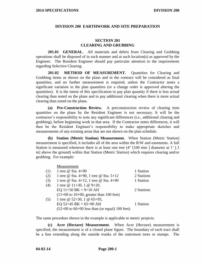
If there are no variations in plan quantity on a Clearing and Grubbing item, the
plan quantity DWR template shall be used and the "Verified Plan Quantity" check box
checked.
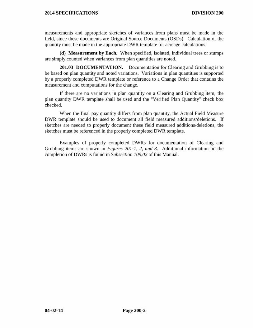
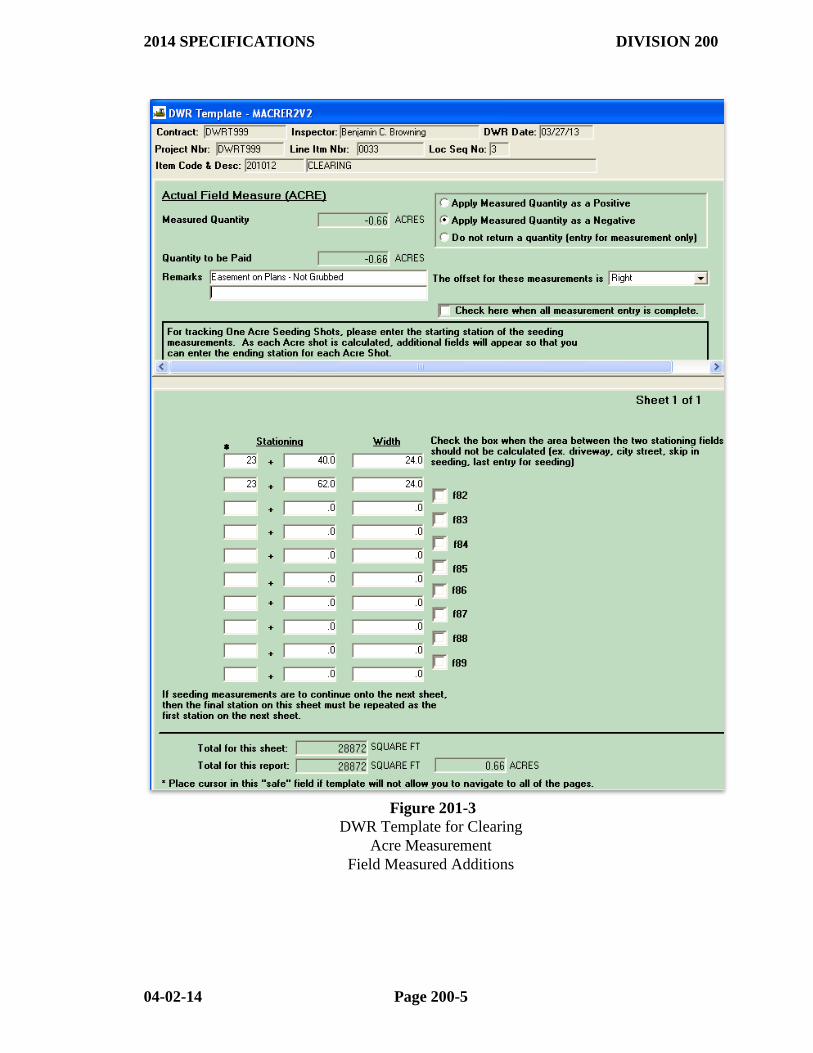
When the final pay quantity differs from plan quantity, the Actual Field Measure
DWR template should be used to document all field measured additions/deletions. If
sketches are needed to properly document these field measured additions/deletions, the
sketches must be referenced in the properly completed DWR template.
Examples of properly completed DWRs for documentation of Clearing and
Grubbing items are shown in Figures 201-1, 2, and 3. Additional information on the
completion of DWRs is found in Subsection 109.02 of this Manual.
2014 SPECIFICATIONS DIVISION 200
04-02-14 Page 200-3
Figure 201-1
DWR Template for Clearing
Station Measurement
Verified Plan Quantity
2014 SPECIFICATIONS DIVISION 200
04-02-14 Page 200-4
Figure 201-2
DWR Template for Clearing
Station Measurement
Field Measured Additions
2014 SPECIFICATIONS DIVISION 200
04-02-14 Page 200-5
Figure 201-3
DWR Template for Clearing
Acre Measurement
Field Measured Additions
2014 SPECIFICATIONS DIVISION 200
04-02-14 Page 200-6
SECTION 202
REMOVAL AND DISPOSAL OF STRUCTURES
202.01 GENERAL. All materials and debris shall be disposed of in such manner
and at such location(s) as approved by the Engineer. Unless otherwise specified in the
contract, all material removed under this item becomes the property of the Contractor.
When there are materials specified on the plans or in the contract to become the
property of someone other than the Contractor, the procedures contained in Subsection
104.04 of this Manual should be followed.
NOTE: Removal and Disposal of water wells (including plugging same) must be
performed in accordance with Arkansas Water Well Construction Commission policies.
Resident Engineers should contact the Construction Office for guidance in this area when
this item is on the plans.
202.02 METHOD OF MEASUREMENT. Quantities for "Removal and
Disposal of __________" as shown on the plans and in the Bid Proposal will be
considered as final quantities, and no further measurement is required, unless the
Resident Engineer and/or the contractor notes significant exception(s) and/or a Change
Order is approved altering the quantities.
The plan quantities must be verified and measurements for revisions (if any) must
be made prior to the work in that area.
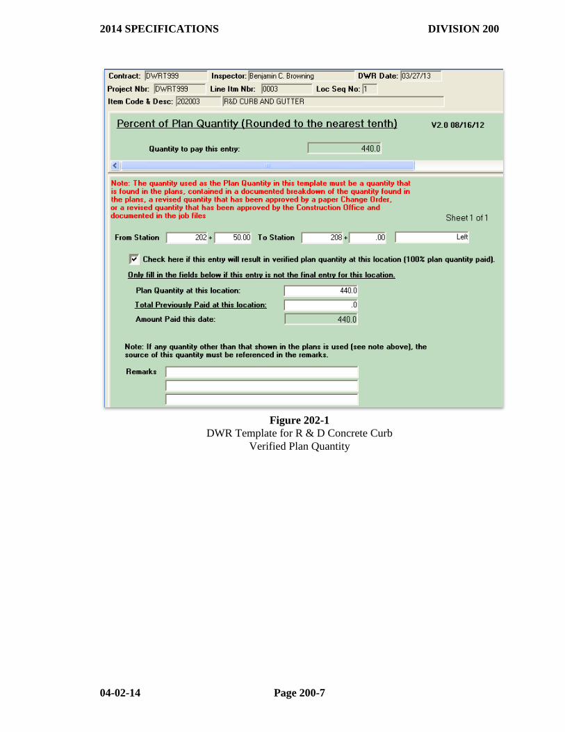
202.03 DOCUMENTATION - CURRENT ESTIMATES. Documentation
shall be DWRs completed in the same manner as those for Clearing and Grubbing items
(See Subsection 201.03 of this Manual).
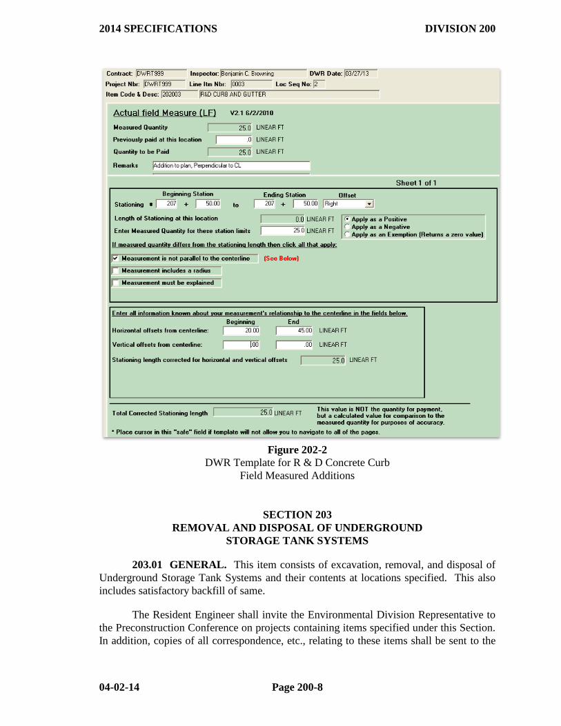
Examples of properly completed DWR templates for Removal and Disposal of
Structures are shown in Figures 202-1 and 2. Additional information on the completion
of DWRs is found in Subsection 109.02 of this Manual.
2014 SPECIFICATIONS DIVISION 200
04-02-14 Page 200-7
Figure 202-1
DWR Template for R & D Concrete Curb
Verified Plan Quantity
2014 SPECIFICATIONS DIVISION 200
04-02-14 Page 200-8
Figure 202-2
DWR Template for R & D Concrete Curb
Field Measured Additions
SECTION 203
REMOVAL AND DISPOSAL OF UNDERGROUND
STORAGE TANK SYSTEMS
203.01 GENERAL. This item consists of excavation, removal, and disposal of
Underground Storage Tank Systems and their contents at locations specified. This also
includes satisfactory backfill of same.
The Resident Engineer shall invite the Environmental Division Representative to
the Preconstruction Conference on projects containing items specified under this Section.
In addition, copies of all correspondence, etc., relating to these items shall be sent to the
2014 SPECIFICATIONS DIVISION 200
04-02-14 Page 200-9
Environmental Division. The Resident Engineer may obtain details concerning the
various testing procedures noted in this Specification from the Environmental Division.
Should the Contractor be allowed to dispose of contaminated material in a solid
waste landfill, he must provide proof to the Resident Engineer that the material was so
disposed.
The Resident Engineer should suspend operations and seek guidance from the
Central Office Construction and Environmental Divisions:
If extensive contamination is encountered,
If "Free Product" is encountered, or
If a tank system not shown on the plans is discovered.
203.02 METHOD OF MEASUREMENT. (a) "Removal and Disposal of
Underground Storage Tank Systems" is measured by the Unit ("Each"), which includes
removal and disposal of the tank, the lines connected to it, and their contents.
(b) "Backfilling Underground Storage Tank Systems" is measured by the Cubic
Yard (Cubic Meter) of the hole from which the tank was removed. This may be
measured by the cross section method with the volume computed by the average end area
method, or by measuring all dimensions and computing the volume.
(c) "Excavation of Underground Storage Tank Systems" is measured by the Cubic
Yard (Cubic Meter). (This is computed using the volume calculated for Backfilling
Underground Storage Tank Systems less the volume of the tank.)
(d) "Treatment or Disposal of Excavated Material" is measured by the Cubic Yard
(Cubic Meter). This is the portion of excavated material where hydrocarbon levels are in
excess of 100 PPM. This may be measured using dimensions, in a windrow, in vehicles,
by cross sections, etc.
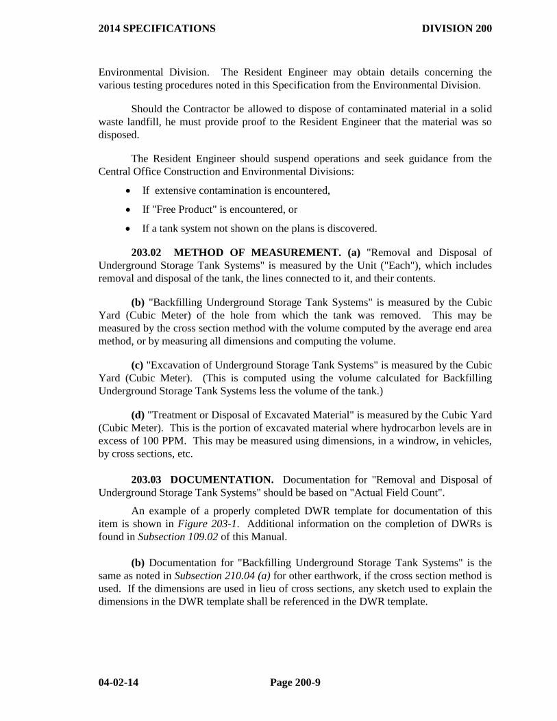
203.03 DOCUMENTATION. Documentation for "Removal and Disposal of
Underground Storage Tank Systems" should be based on "Actual Field Count".
An example of a properly completed DWR template for documentation of this
item is shown in Figure 203-1. Additional information on the completion of DWRs is
found in Subsection 109.02 of this Manual.
(b) Documentation for "Backfilling Underground Storage Tank Systems" is the
same as noted in Subsection 210.04 (a) for other earthwork, if the cross section method is
used. If the dimensions are used in lieu of cross sections, any sketch used to explain the
dimensions in the DWR template shall be referenced in the DWR template.
2014 SPECIFICATIONS DIVISION 200
04-02-14 Page 200-10
(c) Documentation for "Excavation for Underground Storage Tank Systems" shall
consist of a properly completed DWR Template. This DWR Template shall contain
references to any sketch used to explain the volume calculations for the tank that was
removed. It should also contain a reference to the appropriate DWR Template for
"Backfilling Underground Storage Tank Systems" and the calculation of the final
"Excavation for Underground Storage Tank Systems" quantity. (This is computed using
the "Backfilling Underground Storage Tank Systems" amount and subtracting the volume
of the tank.)
(d) Documentation for "Treatment or Disposal of Excavated Material" shall
consist of a properly completed DWR Template. This DWR template should reference
all applicable sketches and cross sections.
Figure 203-1
DWR Template for Removal and Disposal of Underground Storage Tank Systems
SECTION 204
VACANT
SECTION 205
REMOVAL OF EXISTING BRIDGE STRUCTURES
205.01 GENERAL. All materials and debris shall be disposed of in such manner
and at such location(s) as approved by the Engineer. Unless otherwise specified in the
contract, all salvageable material removed under this item remains the property of the
Owner (normally the Department) and shall be handled as Salvage Material (See
Subsection 104.04 of this manual).
2014 SPECIFICATIONS DIVISION 200
04-02-14 Page 200-11
205.02 METHOD OF MEASUREMENT. "Removal of Existing Bridge
Structure (Site No._____)" will be measured on the lump sum basis for each bridge.
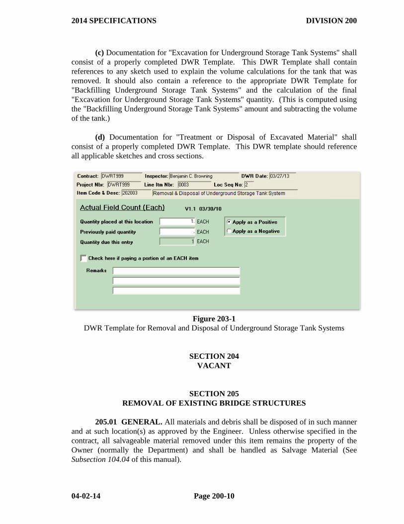
205.03 DOCUMENTATION. Final Estimate documentation for "Removal of
Existing Bridge Structure (Site No.____)" is to be based on "Observation of completed
work". Documentation is a properly completed DWR Template for the Lump Sum unit
of measurement.
An example of a properly completed DWR Template is shown in Figure 205-1.
Additional information on the completion of DWRs is found in Subsection 109.02 of this
Manual.
Figure 205-1
DWR Template for Removal of Existing Bridge Structure
SECTION 206
FLOWABLE SELECT MATERIAL
206.01 GENERAL. Flowable Select Material is generally used for backfilling
RC Box Culverts or Pipe Culverts in areas with limited access to conventional
compaction equipment. This item is also used where a fast installation is needed to
minimize public inconvenience. The Contractor is responsible for preparing and
submitting a mix design; however, the Department is responsible for all acceptance
sampling and testing.
2014 SPECIFICATIONS DIVISION 200
04-02-14 Page 200-12
206.02 METHOD OF MEASUREMENT. Flowable Select Material is
measured by Cubic Yard (Cubic Meter). The quantity shown on the plans will be
considered as the final quantities. No further measurement is required, unless the
Resident Engineer and/or the Contractor notes significant variations between plan
quantities and actual quantities due to changes in alignment or dimensions or to apparent
errors. Excavation carried beyond the limits shown on the plans (for the Contractor’s
convenience) should not be considered as a basis for increasing the plan quantity.
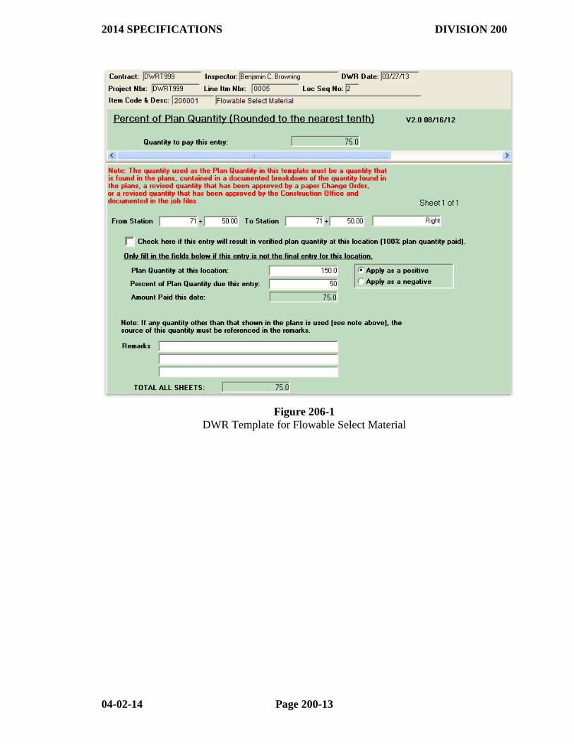
206.03 DOCUMENTATION. Final Estimate documentation for Flowable
Select Material is to be based on plan quantity and noted variations.
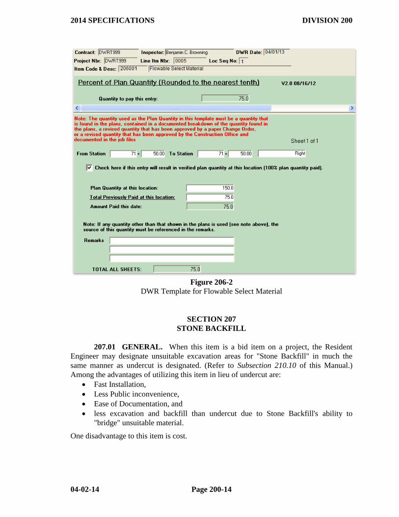
If there are no variations in plan quantity on a Flowable Select Material item, the
plan quantity DWR template shall be used and the "Verified Plan Quantity" check box
checked.
When the final pay quantity differs from plan quantity, the Actual Field Measure
DWR template should be used to document all field measured additions/deletions. If
sketches are needed to properly document these field measured additions/deletions, the
sketches must be referenced in the properly completed DWR template.
Examples of properly completed DWR Templates for documentation of Flowable
Select Material are shown in Figures 206-1 and 2. Additional information on the
completion of DWRs is found in Subsection 109.02 of this Manual.
2014 SPECIFICATIONS DIVISION 200
04-02-14 Page 200-13
Figure 206-1
DWR Template for Flowable Select Material
2014 SPECIFICATIONS DIVISION 200
04-02-14 Page 200-14
Figure 206-2
DWR Template for Flowable Select Material
SECTION 207
STONE BACKFILL
207.01 GENERAL. When this item is a bid item on a project, the Resident
Engineer may designate unsuitable excavation areas for "Stone Backfill" in much the
same manner as undercut is designated. (Refer to Subsection 210.10 of this Manual.)
Among the advantages of utilizing this item in lieu of undercut are:
Fast Installation,
Less Public inconvenience,
Ease of Documentation, and
less excavation and backfill than undercut due to Stone Backfill's ability to
"bridge" unsuitable material.
One disadvantage to this item is cost.
2014 SPECIFICATIONS DIVISION 200
04-02-14 Page 200-15
The Resident Engineer should include these in the consideration as to whether an
unsuitable excavation area should be designated for undercut (Unclassified Excavation
and Compacted Embankment) or Stone Backfill.
NOTE: Prior to authorizing significant use of Stone Backfill, the Resident
Engineer should consult with others (District, Construction Office, Materials Division) to
determine if other stabilization methods may be more appropriate and/or cost effective.
NOTE: Stone Backfill is paid only for locations “designated by the Engineer”.
Should a contractor utilize this material for his convenience without Resident Engineer
authorization, it should be considered at his expense.
207.02 METHOD OF MEASUREMENT. Stone Backfill is measured by the
Ton (Metric Ton).
When backfilling with stone backfill to the subgrade elevation or to an elevation
below subgrade when directed by the RE, the top 4” – 6” (100 mm - 150 mm) of the
Stone Backfill must be made up of a material meeting the requirements of Class 7
Aggregate Base Course. This material is measured and paid for as Stone Backfill.
207.03 DOCUMENTATION OTTRS shall be used as OSDs for Stone Backfill.
No further documentation is necessary for payment. Excavation is not measured for
payment in conjunction with Stone Backfill.
SECTION 208
FENCE REMOVED AND RECONSTRUCTED
208.01 GENERAL. All materials and debris shall be disposed of in such manner and at
such location(s) as approved by the Engineer. Unless otherwise specified, material
removed and not used in the reconstruction becomes the property of the Contractor.
The Contractor is required to replace, at his expense, materials which are unusable and
which are required for proper reconstruction.
208.02 METHOD OF MEASUREMENT. "Fence Removed and Reconstructed" will
be measured by Linear Foot (Meter) of fence re-erected under this item. Measurement of
the fence in its original position is not required as it has no bearing on the quantity for
payment.
Gates removed and reconstructed as part of a fence will not be paid for separately.
Gates will only be measured and paid for when shown separately on the plans. Such
separate gates that are removed and reconstructed will be measured by the unit (Each) in
the new location.
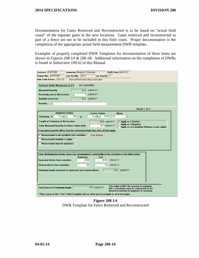
208.03 DOCUMENTATION. Documentation for Fence Removed and Reconstructed
is to be based on "actual field measurement" of the fence in its final position. Proper
documentation is the completion of the appropriate actual field measurement DWR
template.
2014 SPECIFICATIONS DIVISION 200
04-02-14 Page 200-16
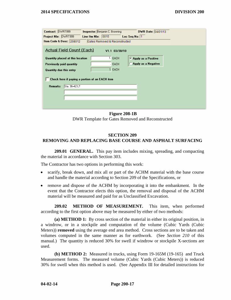
Documentation for Gates Removed and Reconstructed is to be based on "actual field
count" of the separate gates in the new locations. Gates removed and reconstructed as
part of a fence are not to be included in this field count. Proper documentation is the
completion of the appropriate actual field measurement DWR template.
Examples of properly completed DWR Templates for documentation of these items are
shown in Figures 208-1A & 208-1B. Additional information on the completion of DWRs
is found in Subsection 109.02 of this Manual.
Figure 208-1A
DWR Template for Fence Removed and Reconstructed
2014 SPECIFICATIONS DIVISION 200
04-02-14 Page 200-17
Figure 208-1B
DWR Template for Gates Removed and Reconstructed
SECTION 209
REMOVING AND REPLACING BASE COURSE AND ASPHALT SURFACING
209.01 GENERAL. This pay item includes mixing, spreading, and compacting
the material in accordance with Section 303.
The Contractor has two options in performing this work:
scarify, break down, and mix all or part of the ACHM material with the base course
and handle the material according to Section 209 of the Specifications, or
remove and dispose of the ACHM by incorporating it into the embankment. In the
event that the Contractor elects this option, the removal and disposal of the ACHM
material will be measured and paid for as Unclassified Excavation.
209.02 METHOD OF MEASUREMENT. This item, when performed
according to the first option above may be measured by either of two methods:
(a) METHOD 1: By cross section of the material in either its original position, in
a windrow, or in a stockpile and computation of the volume (Cubic Yards (Cubic
Meters)) removed using the average end area method. Cross sections are to be taken and
volumes computed in the same manner as for earthwork. (See Section 210 of this
manual.) The quantity is reduced 30% for swell if windrow or stockpile X-sections are
used.
(b) METHOD 2: Measured in trucks, using Form 19-165M (19-165) and Truck
Measurement forms. The measured volume (Cubic Yards (Cubic Meters)) is reduced
30% for swell when this method is used. (See Appendix III for detailed instructions for
2014 SPECIFICATIONS DIVISION 200
04-02-14 Page 200-18
this form.) If DWR templates have been activated on a project then the template shall be
used for documentation in lieu of any paper forms.
209.03 DOCUMENTATION.
(a) METHOD 1. If computation of the Final Pay Quantity has been made, the
Actual Field Measurement – Final Measurement DWR template should be used. In
addition, the X-section books or SDMS file and computer-run computation sheets must
accompany the Final Estimate.
If computation of the Final Pay Quantity has not been completed (i.e., the
stockpile is still being constructed or the material is still being removed from the
roadway), the Percent of Plan Quantity DWR template should be used. No further
documentation is necessary.
Documentation is to be completed in the same manner as shown in Section 210
for earthwork.
(b) METHOD 2. When this item is measured in trucks, the applicable Forms
19-165 (19-165M), Daily Report of Volumetric Hauling, will be the documentation for
Current Estimates. The computation of the 30% reduction must be shown on each form.
If DWR templates have been activated on a project then the template shall be used for
documentation in lieu of any paper forms.
SECTION 210
EXCAVATION AND EMBANKMENT
210.01 GENERAL (a) Quality Control and Acceptance Sampling and
Testing. Monitoring of Contractor acceptance testing is critical in embankment
operations. Unlike other portions of the Specifications, only Contractor test results are
used for acceptance of embankment construction. Therefore, the Department must make
maximum use of verification tests in order to ensure that the test results reported by the
Contractor are accurate. See Subsection 106.04 of this Manual for additional information
on verification testing. See the Manual of Field Sampling and Testing Procedures for
specific test procedures and frequencies for verification testing.
As stated in Subsection 210.02(b) of the Specifications, in addition to the required
acceptance tests, the Engineer may require the Contractor to test any location that appears
defective. This tool should be used to ensure that no suspect areas are sweepingly
accepted by the contractor’s acceptance test. Remember that in-place density is not the
only factor governing the acceptance of embankment material; stability is crucial to the
final product.
(b) Verification of Line and Grade. It is the Resident Engineer's responsibility to
compute planned grades. Grades may be calculated by hand or by computer.
On all projects, and particularly on those involving widening or matching an
existing grade, the Resident Engineer shall take sufficient "on-ground" profiles, cross-
2014 SPECIFICATIONS DIVISION 200
04-02-14 Page 200-19
sections, and other checks to verify the plan grades, typical sections, and/or plan original
cross sections. This verification shall be accomplished prior to performing any layout or
other work which could be affected by the grades and/or typical sections.
(1) Projects WITHOUT Roadway Construction Control. When the pay item
"Roadway Construction Control" is NOT included in the contract, the Resident Engineer
is responsible for providing the Contractor with sufficient line and grade stakes to
construct the work. Computation and documentation for these stakes should be
performed using the manual method as described in the "Construction Survey Course".
The computer may be used to assist with the computations.
While the Contractor must satisfy themselves as to the correctness and meaning of
all stakes, measurements and marks before commencing work, the Department and,
ultimately, the Resident Engineer is responsible for the accuracy of the information given
the Contractor. It is in the best interest of the Contractor and the Resident Engineer to
ensure, prior to performing the work, that all the computations and stakeout information
used to construct the project are accurate and in accordance with the plans and that the
Contractor understands the meaning of the markings on the stakes. In addition, it is the
Resident Engineer's obligation to check the Contractor's work during construction and
ensure that the work is being constructed in accordance with the line and grade staked.
The Contractor is required by Subsection 105.09 of the Standard Specifications to
preserve all stakes and marks. Occasional and inadvertent destruction of slope stakes,
etc., is inherent in the nature of the work; however, if the stakes, etc., are willfully or
carelessly destroyed or disturbed by the Contractor, the cost of replacing them will be
charged to the Contractor and deducted from the payment for the work.
(2) Projects WITH Roadway Construction Control. When "Roadway
Construction Control" IS included in the contract, the Contractor is responsible for
computing all required grades and for setting (and replacing, if necessary) all slope stakes
and/or grade stakes required. The Resident Engineer is still responsible for computing
the centerline and shoulder elevations in order to check the Contractor's work. The
Resident Engineer should randomly check the stakes and blue tops set by the Contractor
in order to ensure substantial compliance with the plans.
(c) Location of Borrow Pits. The Department must approve the location of
proposed borrow pits prior to their use. The Contractor is required to notify the Resident
Engineer in writing of the location of the proposed pit. Refer to Subsection 107.10 of the
Specifications and Subsection 107.03(b) of this Manual for the procedures to be followed
in requesting clearance for a proposed pit. The physical requirements for borrow pits are
contained in Subsection 106.02 of the Specifications.
NOTE: The specifications do not require the Resident Engineer to obtain a pit
agreement or release from the Contractor.
210.02 METHOD OF MEASUREMENT. (a) Common Excavation, Rock
Excavation, Unclassified Excavation, and Borrow. Each of these items is measured by
the Cubic Yard (Cubic Meter) in its original position by the cross section method, either
by conventional, electronic, or photogrammetric methods, and the volume is computed by
2014 SPECIFICATIONS DIVISION 200
04-02-14 Page 200-20
the average end area method. In unusual situations, other methods may be used, with the
prior approval of the Construction Office.
NOTE: On all projects let in the October 2011 letting or after, the InRoads
computer program MUST be used for these computations. InRoads can be used for
conventional or photogrammetric cross-sections and must be used for all data collected
using the Survey Data Management System (SDMS).
NOTE: The Specifications allow jobs with small quantities of Borrow to be
measured in vehicles, using Method 2 of Subsection 209.02. As noted in Section 209 of
this Manual, this method requires the yardage measured in vehicles to be reduced by
30%. "Jobs with small quantities of borrow" is interpreted to be those with less than
3000 cubic yards (2500 cubic meters) in the contract. The Resident Engineer should
contact the Construction Office for permission to use vehicular measurements in other
instances. (The use of vehicular measurement must be documented. See subsection
109.01(c) of this manual.)
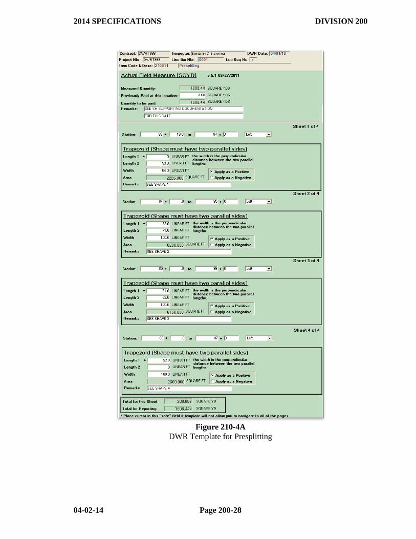
(b) Presplitting is measured by the Square Yard (Square Meter) of plane surface
of the final presplit cut face. Overbreakage due to excessive blasting is deducted from
this measurement.
Measurements for presplitting should be taken at the same time final X-sections
are taken. A measurement, parallel to the slope, shall be taken at each X-section and
recorded on the appropriate DWR template.
(c) Compacted Embankment is measured by the (Cubic Meter) in its final
position using the cross section method (conventional, electronic, or photogrammetric
procedures) and computed using the average end area method. It includes all compacted
fill volume within the right-of-way and easements.
NOTE: InRoads is to be used for these computations. When the item
"Compacted Embankment" is used, Special Compaction of Earthwork is a subsidiary
item.
(d) Earthwork Measurement Options. Subsection 210.12(f) of the Standard
Specifications provides four options for the measurement of earthwork items:
1. Obtaining original and/or final cross section in the field or by photogrammetric
methods.
2. Use the preliminary (plan) cross sections used in the design of the project as the
original cross sections.
3. Use templated final cross sections in lieu of cross sections taken in the field.
4. Use a computer program (INROADS) to compute quantities from terrain models
developed from field and/or photogrammetric data.
Options 1 and 4 can be used alone or in any combination with any of the other three
options; however, options 2 and 3 cannot be used together. Before selecting option 2
or option 3, the RE must verify or check the plans to determine that the plan cross-
2014 SPECIFICATIONS DIVISION 200
04-02-14 Page 200-21
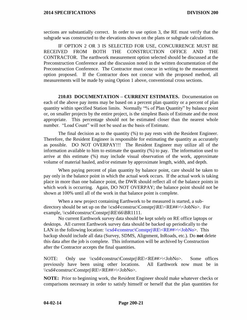
sections are substantially correct. In order to use option 3, the RE must verify that the
subgrade was constructed to the elevations shown on the plans or subgrade calculations.
IF OPTION 2 OR 3 IS SELECTED FOR USE, CONCURRENCE MUST BE
RECEIVED FROM BOTH THE CONSTRUCTION OFFICE AND THE
CONTRACTOR. The earthwork measurement option selected should be discussed at the
Preconstruction Conference and the discussion noted in the written documentation of the
Preconstruction Conference. The Contractor must concur in writing to the measurement
option proposed. If the Contractor does not concur with the proposed method, all
measurements will be made by using Option 1 above, conventional cross sections.
210.03 DOCUMENTATION – CURRENT ESTIMATES. Documentation on
each of the above pay items may be based on a percent plan quantity or a percent of plan
quantity within specified Station limits. Normally “% of Plan Quantity” by balance point
or, on smaller projects by the entire project, is the simplest Basis of Estimate and the most
appropriate. This percentage should not be estimated closer than the nearest whole
number. “Load Count” will not be used as the basis of Estimate.
The final decision as to the quantity (%) to pay rests with the Resident Engineer.
Therefore, the Resident Engineer is responsible for estimating the quantity as accurately
as possible. DO NOT OVERPAY!!! The Resident Engineer may utilize all of the
information available to him to estimate the quantity (%) to pay. The information used to
arrive at this estimate (%) may include visual observation of the work, approximate
volume of material hauled, and/or estimate by approximate length, width, and depth.
When paying percent of plan quantity by balance point, care should be taken to
pay only in the balance point in which the actual work occurs. If the actual work is taking
place in more than one balance point, the DWR should reflect all of the balance points in
which work is occurring. Again, DO NOT OVERPAY; the balance point should not be
shown at 100% until all of the work in that balance point is complete.
When a new project containing Earthwork to be measured is started, a sub-
directory should be set up on the \\csd4\construc\Constprj\RE\<RE##>\<JobNo>. For
example, \\csd4\construc\Constprj\RE\66\BR1111.
No current Earthwork survey data should be kept solely on RE office laptops or
desktops. All current Earthwork survey data should be backed up periodically to the
LAN in the following location: \\csd4\construc\Constprj\RE\<RE##>\<JobNo>. This
backup should include all data (Survey, SDMS, Alignment, InRoads, etc.). Do not delete
this data after the job is complete. This information will be archived by Construction
after the Contractor accepts the final quantities.
NOTE: Only use \\csd4\construc\Constprj\RE\<RE##>\<JobNo>. Some offices
previously have been using other locations. All Earthwork now must be in
\\csd4\construc\Constprj\RE\<RE##>\<JobNo>.
NOTE: Prior to beginning work, the Resident Engineer should make whatever checks or
comparisons necessary in order to satisfy himself or herself that the plan quantities for
2014 SPECIFICATIONS DIVISION 200
04-02-14 Page 200-22
Earthwork items are substantially correct. As the work progresses, the Resident Engineer
should attempt to compare the actual shrinkage with the planned shrinkage and should
remain cognizant of any modifications that would cause the final quantity to vary
significantly from the plan quantity. In doing this, the Resident Engineer avoids
overpayment to the Contractor on Current Estimates and is able to more easily explain
overruns and underruns on the Final Estimate.
NOTE: Plan quantity (as revised by approved Change Orders) may not be
exceeded without actual field measurements to support the overrun.
It is very important that the Resident Engineer utilize all of the above information
in conjunction with the actual work performed in determining the volume of the
earthwork to be submitted for payment. This volume should be reduced by an
appropriate quantity until the slopes, ditches, and roadway are brought to final acceptable
section, and any other required subsidiary work has been completed. Such reduction
should reflect the extent of subsidiary work remaining in specific segments which can be
determined readily (such as balance points, station limits, entire project, etc.). As that
work is satisfactorily accomplished, payment will be made therefor. Acceptance of the
work will not be made except as defined in Section 105.17 of the Standard Specification,
and the contractor shall remain responsible as defined in Section 107.16.
When earthwork is completed prior to project completion, the Resident Engineer
should ensure earthwork quantities are promptly measured and the final cross-section
measurements are submitted to the Contract Estimates Section for pre-checking. Once
the earthwork is complete, payment for 100% of the plan quantity (as revised by approved
change orders, with field measured additions and deletions) should be made to the
Contractor on the next progress estimate. This payment may occur before final
cross-sections have been taken and resulting quantities determined. After pre-checking,
earthwork payments shall be promptly adjusted to the measured quantities. Payment of
these pre-checked quantities should not be held until submission of the final estimate.
Examples of properly completed DWR Templates for documentation of these
items are shown in Figures 210-1 and 210-2A/B. Additional information on completion
of DWRs is found in Subsection 109.02 of this Manual.
In the case of Borrow measured in vehicles, Form 19-165M (19-165), "Daily
Report of Volumetric Hauling" will be appropriate documentation. The computation of
the 30% reduction for swell must be shown on each completed form. The Truck
Measurement Form (Form 19-507M or 19-507) must accompany the first daily report that
the truck appears on. If DWR templates have been activated on a project then the
template shall be used for documentation in lieu of any paper forms. The Truck
Measurement Form (Form 19-507M or 19-507) must be submitted to Contract Estimates
at the first inclusion of a truck in a DWR template.
Contract Estimates needs to be notified via E-Mail on jobs needing to be pre-
checked. The following applies when a job is to be pre-checked:
(1) Any OSD drawing or calculation needs to be sent to Contact Estimates during
the time of the pre-check notification. The Final Earthwork Summary must be
2014 SPECIFICATIONS DIVISION 200
04-02-14 Page 200-23
in the \\csd4\construc\Constprj\RE\<RE##>\<JobNo> subdirectory.
Earthwork cannot be reviewed without the Earthwork Summary.
(2) If you have not heard back from Contract Estimates in a few days confirming
they are aware of the Earthwork, a follow up email or phone call should be
made.
Earthwork jobs that do not require pre-checking can be submitted along with the
normal final estimate. All original OSDs must be included with the final estimate
submittal.
210.04 DOCUMENTATION. (a) Common Excavation, Rock Excavation,
Unclassified Excavation, and Borrow. The Original Source Documentation which
must accompany the Final Estimate for each of the above items includes:
(1) Cross section notes, including check level information.
(2) Computer-generated plots. The Resident Engineer shall review plots of all
computer-generated cross sections. It is not necessary or desirable to routinely
print hard copies of all cross sections. However, any hard copies of plots printed
should be included with the Final Estimate. If the Resident Engineer feels it
necessary to obtain a hard copy plot of an entire project or a large portion of a
project, an IOM to the State Construction Engineer (Attention: Final Estimates)
should be sent requesting this, along with applicable data files on a Compact Disk
or other media.
(3) An Earthwork Summary must be submitted with all Earthwork jobs, an example
of this summary can be found at \\csd4\construc\Constprj\RE\Earthwork
Summary.xls. The Earthwork Summary must contain the following:
a) All the quantities being paid and the method of measurement. This includes
all quantities measured by X, Y, Z measurements.
b) The InRoads .FWD files that are being paid.
c) Tab 2 should contain all deductions for structures being picked up with the
measured fill. (R.C. Pipes, R. C. Boxes, Sidewalks…etc.)
The Earthwork Summary should be kept in the
\\csd4\construc\Constprj\RE\<RE##>\<JobNo> with the rest of the Earthwork
data.
NOTE: When Borrow is measured in vehicles, the OSD will be the "Daily
Report(s) of Volumetric Hauling", Form 19-165M (19-165) completed for this
item. If DWR templates have been activated on a project then the template shall
be used for documentation in lieu of any paper forms. No further documentation
is necessary.
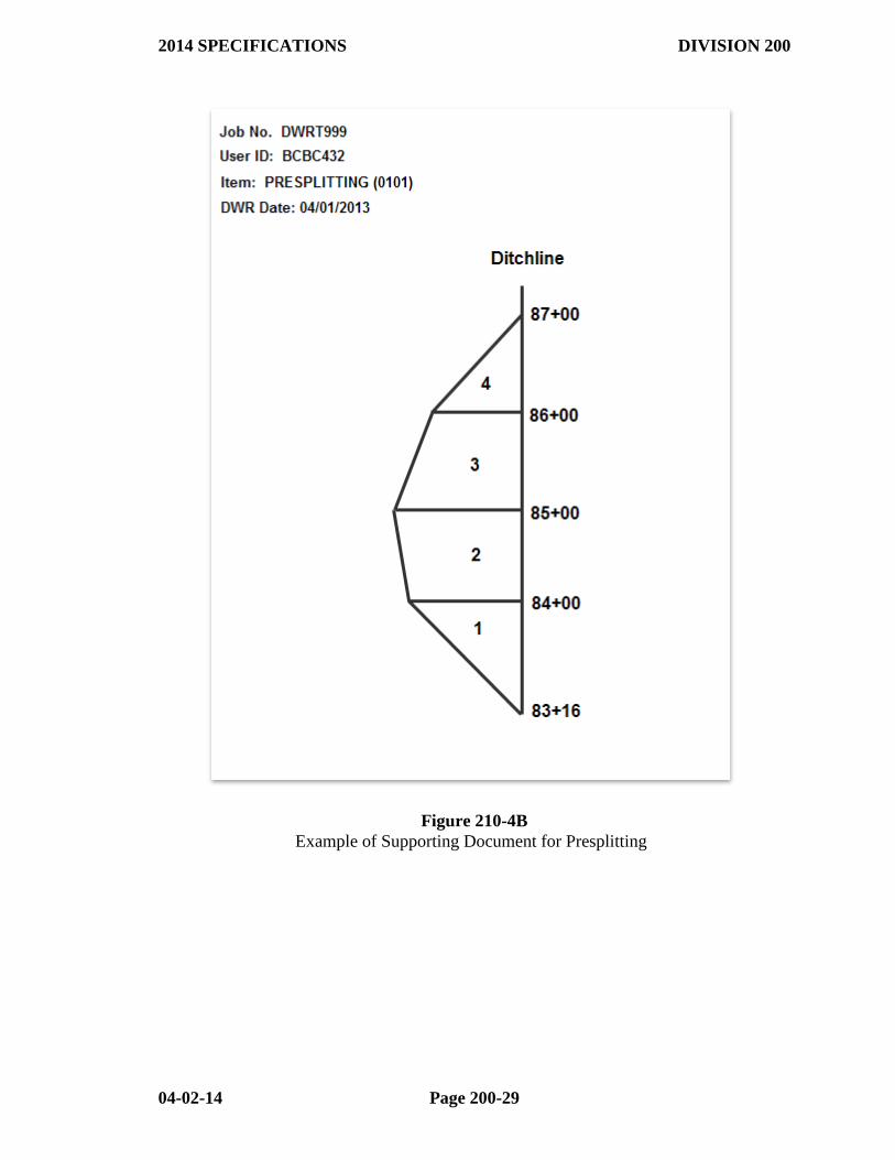
(b) Presplitting is documented for the Final Estimate using a DWR template.
This DWR template should reference all applicable sketches. See example DWR in
Figure 210-4A/B.

2014 SPECIFICATIONS DIVISION 200
04-02-14 Page 200-24
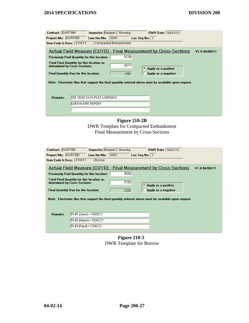
(c) Compacted Embankment is documented in the same manner as the
items in (a) above.
Examples of properly completed DWR Templates are shown in Figures 210-2A/B, 210-3.
2014 SPECIFICATIONS DIVISION 200
04-02-14 Page 200-25
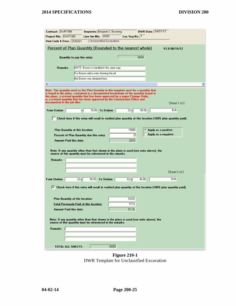
Figure 210-1
DWR Template for Unclassified Excavation

2014 SPECIFICATIONS DIVISION 200
04-02-14 Page 200-26
Figure 210-2A
DWR Template for Compacted Embankment
2014 SPECIFICATIONS DIVISION 200
04-02-14 Page 200-27
Figure 210-2B
DWR Template for Compacted Embankment
Final Measurement by Cross-Sections
Figure 210-3
DWR Template for Borrow
2014 SPECIFICATIONS DIVISION 200
04-02-14 Page 200-28
Figure 210-4A
DWR Template for Presplitting
2014 SPECIFICATIONS DIVISION 200
04-02-14 Page 200-29
Figure 210-4B
Example of Supporting Document for Presplitting
2014 SPECIFICATIONS DIVISION 200
04-02-14 Page 200-30
210.05 PHOTOGRAMMETRY. Original and Final X-sections may be taken by
conventional or photogrammetric procedures. There are numerous factors that determine
the applicability of photogrammetric procedures to a particular project. Prior to
requesting photogrammetry, the Resident Engineer should consider the availability of
construction personnel, length of the project, and the type of terrain. Preferably, the
project should be a minimum length of one mile (1.6 kilometers) or an interchange or
borrow pit area of at least 50 acres (20 hectares) before aerial photography is considered.
If the Resident Engineer determines that aerial photography is desirable, he should make
a request by memo to the District Engineer, who will in turn make the request to the
Surveys Division.
Once the determination has been made to use aerial photography:
The Resident Engineer will be responsible for:
1. Coordinating with the District Engineer to provide any clearing that is
necessary around aerial photography targets.
2. Placing and maintaining the targets until the aerial photography is complete.
(Target materials may be obtained from the Photogrammetry Section.)
3. Coordinating with the Contractor or District Engineer to remove vegetation
to the extent that the aerial photography will be satisfactory.
4. Providing the vertical and horizontal control to the targets.
5. Providing the Surveys Division with any information relative to alignment
changes.
The Photogrammetry Section will be responsible for:
1. Providing a map showing target size, shapes and locations of the targets.
2. Flying the aerial photography and providing the necessary X-sections to the
Resident Engineer.
Other things to consider when using aerial photography are:
Detours, channel changes and other minor earthwork most likely will have to be
X-sectioned by conventional methods.
If the aerial photography for final X-sections is not flown at the time the subgrade
and slopes are completed, it may be necessary to make adjustments for base,
paving, sod mulch, etc.
210.06 Original Cross Sections (Traditional). (a) Original X-sections become
the basis for later calculations of earthwork quantities. They must be taken with great
care and recorded in the format shown in Appendix 2 of the "Construction Survey
Course".
Particular attention must be given to the following points:
Ensure that level notes are arithmetically correct.
2014 SPECIFICATIONS DIVISION 200
04-02-14 Page 200-31
Take ALL X-sections perpendicular to the Centerline or Base line.
(Perpendicular to a curve is along a radial line). NEVER TAKE A
CROSS SECTION ON A SKEW!! A right angle prism or a transit may
be used, or stakes may be set at the R/W lines to assist in taking X-sections
perpendicular to the Centerline.
Take X-sections wide enough to cover ALL of the work. Normally, this
will be from R/W line to R/W line (including permanent and temporary
easements). It is better to take Original X-sections too wide than to extend
those that were taken too narrow. Unless a change in design or alignment is
involved, extending original X-sections can--and should--be avoided by
taking them with sufficient width initially. If, due to an unforeseen change
in design or alignment, work must be done beyond the limits of the original
X-sections, they must be extended. The extended X-section notes MUST
be taken before any work is done in the area. The extended X-section shots
must be added to the original X-section notes and must be converted either
to elevations or to the same Instrument Height (H.I.) to which the originals
were referenced. The notes must be recorded in such manner that they can
be checked by persons not familiar with the project.
When there are separate roadways intersecting (such as ramps and loops at
an interchange), match lines should be established and used for both the
original and final X-sections. The best way to establish match lines is to
use a plan layout drawing (to scale) of the interchange. Scale distances and
stationing from the drawing and draw the match lines to verify that all of
the area is covered. Be sure to take both the original and final X-sections
EXACTLY to the established match line points.
When establishing match lines, be sure that every X-section is
perpendicular to the Centerline (or on a radial line in curves). Also, set the
match lines so that when a section crosses a ditch line it is as nearly
perpendicular to the ditch line as possible. Match lines should be
referenced.
Take intermediate sections so as to minimize interpolation after the finals
have been taken. Suggestion: Review the profile and plan X-sections to
anticipate locations for sections, i.e., equations, transition from cut to fill,
etc. A list of these locations may be made in the back of the X-section book
or on scratch paper for ready reference by the party chief. Determine from
the profile sheets the stations where the profile line crosses the natural
ground line and take a section at these stations. These will be as close to
the cut-to-fill transition points as can be reasonably determined in advance.
Take sections in increasing station order. Record stations in proper
sequence, making notes clearly legible. Rarely will the project be cleared in
such a manner that cross sectioning can begin at the beginning of the
project and proceed with uninterrupted stationing to the end of the project.
When it is necessary to take sections out of sequence, do not recopy the
notes in order to have consecutive stationing from the beginning at the book
2014 SPECIFICATIONS DIVISION 200
04-02-14 Page 200-32
to the end. At the end of a series of sections, refer to the book and page
number where the next consecutive station may be found.
At the beginning of a series of stations, refer to the book and page number
where the preceding station may be found.
Refer ALL rod readings within a X-section to the "Height of Instrument"
(H.I.) used in the level notes (the primary level). The Centerline (or Base
Line) shot should normally be taken with the primary level. When the rod
cannot be read with the instrument (either too high or too low) a hand level
or another instrument setup MUST be used. DO NOT "BOOT" THE ROD
OR ATTEMPT TO GUESS AT THE ROD READING.
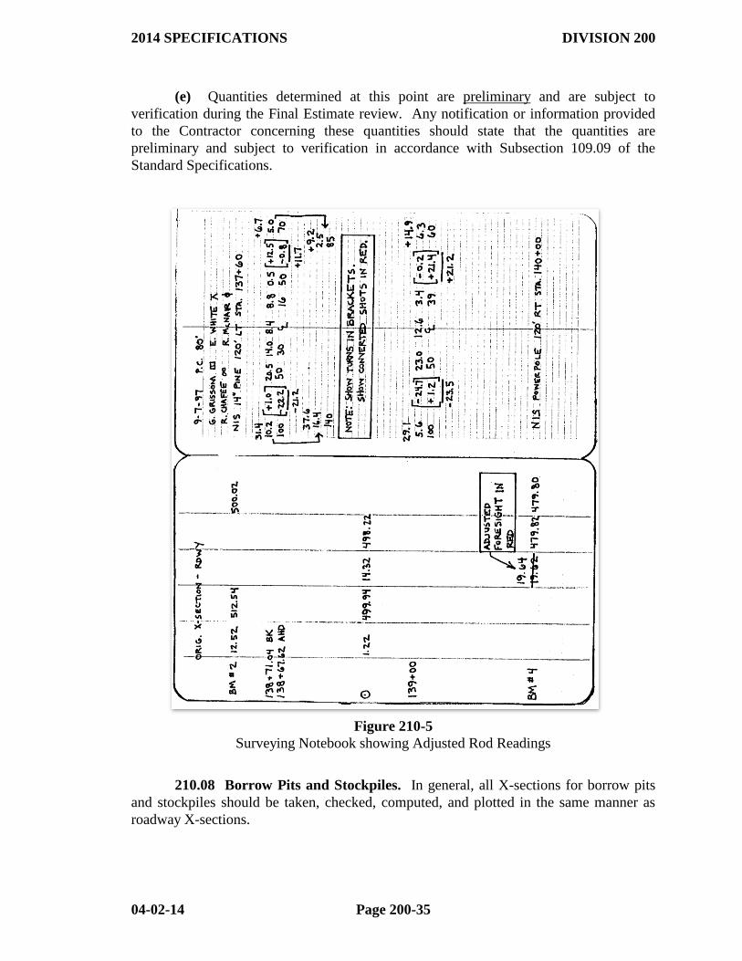
a) Record the turn -- both foresight and backsight -- in the X-section
notes and record the rod readings beyond the turn. Compute the
adjusted rod readings and record the adjusted readings IN RED
immediately above the regular readings. See the example in Figure
210-5.
b) If there are several consecutive stations in which a turn is required,
considerable time can be saved by using two (or more) levels set up
simultaneously.
Measure distances from the Centerline (or Base Line) to the X-section shots
HORIZONTALLY. Be particularly careful on steep slopes to ensure
horizontal measurement.
NOTE: The computer Earthwork program WILL accept two rod readings or
elevations at the same horizontal distance, such as at the face of a curb or
wall.
NOTE: If a Cross section is located entirely on one side of the centerline (or
baseline), a centerline shot is NOT necessary.
Take ONE X-section at each equation in stationing.
Ensure that all Field and Level books are properly identified as to Job
Number and are clearly indexed.
Date all entries, list party members, and indicate weather conditions.
If the plans contain negative stationing, or if it is necessary for borrow pits to
go back from 0+00, set up an equation that utilizes positive stationing. DO
NOT USE NEGATIVE STATION NUMBERS.
SUGGESTION: For borrow pits, etc., begin stationing with 10+00 (or larger)
instead of 0+00.
If an error is made in recording the notes, draw a single line through the
error and record the correction next to the error. DO NOT ERASE!!!
2014 SPECIFICATIONS DIVISION 200
04-02-14 Page 200-33
(b) ALL original X-section notes should be entered in the Resident Engineer's
computer, using INROADS, as soon as they are completed and the following checks have
been made:
The notes are checked for legibility.
The notes have been dated and the survey crew identified.
All level circuits are shown and are arithmetically correct.
NOTE: When a turn is taken through a Bench Mark, show the actual foresight.
The computer program will accept a new bench mark at any point.
All adjusted rod readings have been computed and recorded in RED.
The segment, job, borrow pit, etc., is fully identified. Also note in the
Cross section book the USR (PC) file name when it is punched.
For borrow pits, etc., a sketch of the area must be included along with a
written description. Include the location of the pit, etc., relative to the
geometry of the roadway and the property owner's name and address.
Line through errors and write the correction next to the error. DO NOT
ERASE!!
The books are marked with the Job number, Resident Engineer number,
etc., and are properly indexed.
DO NOT HOLD ORIGINALS WHILE WAITING FOR TIME TO TAKE
FINALS!
The Resident Engineer should check the notes against the printouts and make all
necessary corrections to the USR (data) file and the Cross section book. Be especially
careful when proofreading the station numbers and the foresights and backsights.
(d) Driveways. It is usually easier and simpler to take the Original and Final
roadway X-sections as though the driveways did not exist, then take separate X-sections
for driveways, if necessary. If driveways are X-sectioned with the roadway, at least five
(5) separate, complete sections are required to show each driveway.
210.07 Final Cross Sections (Traditional). (a) Final X-sections shall be taken
and recorded in the same manner as that required for the original sections. The points to
check on the finals include most of the points listed under the original sections. Prior to
taking the Final X-sections, Resident Engineer personnel should:
Make a list of the EXACT stationing of the originals in order that an entire
Final section can be taken at each original location. A Final X-section is
required at every Original X-section location except as follows:
Do not take a Final X-section at a 0.0 section. Simply list the station
number and "0.0 section".
Between 0.0 sections where NO earthwork was done (such as beneath
a bridge between the toes of the bridge end slopes), no Final X-
sections are needed. Draw a line through any Original X-sections
2014 SPECIFICATIONS DIVISION 200
04-02-14 Page 200-34
taken in this location and note that they are deleted due to no work
being done. Be sure to line out the originals both in the books and on
the printouts. These sections should also be deleted from the USR
computer file.
Instruct the survey party to take all Final sections completely across the
work area from construction limit to construction limit. It is not necessary
to take Final X-sections as wide as the Originals were taken when no work
was done beyond a certain point; in fact, it is better to stop at the limits of
construction. THE ORIGINALS MUST BE AT LEAST AS WIDE AS
THE FINALS. When match lines are used, be sure that the Final X-
sections are taken EXACTLY to the match line points.
(b) Final sections should be taken at those locations where a section is needed to
accurately show the work even though no original section was taken there. The original
sections required for computations are interpolated by the computer program. IT IS NOT
DESIRABLE FOR RESIDENT ENGINEER PERSONNEL TO INTERPOLATE THESE
ORIGINAL CROSS SECTIONS BY HAND.
FINAL AND ORIGINAL CROSS SECTIONS MUST BE TAKEN FROM
THE SAME BASE LINE, OR CENTERLINE, AND FROM THE SAME
VERTICAL CONTROL DATUM.
(c) As soon as the Final X-sections have been taken, the same checks as are
required for the originals should be made. The Resident Engineer must also make sure
that 0.0 sections are properly identified and recorded. There should be NO rod readings
at 0.0 sections on the final X-sections.
(d) After the printouts of the X-sections have been proofread, the Resident
Engineer should review the plots on the computer monitor and the volume sheets.
Particular attention should be paid to tie shots. Note that the AHTD Earthwork program
will mark a station number with an asterisk when the tie exceeds 0.3 m (1.0 foot) (or the
closure specified) --unless the tie is at the Centerline or Base line. This is not available
on InRoads. The individual cross sections must be looked at to insure that the ties do not
exceed 0.3 m (1.0 foot). TAKE TIME TO LOOK AT THE PLOTS ON THE
COMPUTER SCREEN! If the plotted X-section does not look right, there is probably
an error or an explanation is required. Note that ALL ties in excess of 1.0 foot MUST be
corrected or explained. The plots are made from the punched data, so if there is an error
in a plot, the printout must be corrected. The notes in the book may also require
correction. Be sure to check both.
If any errors are found during the proofreading or review, make the appropriate
corrections and rerun the program.
If there are no errors found during proofreading or review, (or after all corrections
have been made), the first page of each separate run and any hard copies of plots should
be stamped "CORRECT", dated and signed in the space provided.
2014 SPECIFICATIONS DIVISION 200
04-02-14 Page 200-35
(e) Quantities determined at this point are preliminary and are subject to
verification during the Final Estimate review. Any notification or information provided
to the Contractor concerning these quantities should state that the quantities are
preliminary and subject to verification in accordance with Subsection 109.09 of the
Standard Specifications.
Figure 210-5
Surveying Notebook showing Adjusted Rod Readings
210.08 Borrow Pits and Stockpiles. In general, all X-sections for borrow pits
and stockpiles should be taken, checked, computed, and plotted in the same manner as
roadway X-sections.
2014 SPECIFICATIONS DIVISION 200
04-02-14 Page 200-36
(a) Borrow pits normally should be laid out with the Base line along one side of
the pit, rather than through the center. Always locate and reference the Base Line so that
it can be re-established in the EXACT same location.
If the pit is located reasonably close to the roadway, check levels should be run
and bench marks established for the pit from a roadway Bench Mark. If the Bench Marks
for the pit are NOT established from a known elevation, at least two (2) BM's MUST be
established for the pit (using an assumed elevation) and check levels run between them.
Both BM's should be so located that they will not be disturbed by the borrow operations.
Always have at least two (2) BM's available for each Borrow Pit. In addition, a
sketch of the pit area must be made and recorded in the X-section book. Include a
description of the location of the pit relative to the roadway.
The pit area should be stripped before Original X-sections are taken, and the Final
X-sections should be taken before the topsoil is replaced. (See Subsection 106.02 of the
Standard Specifications.)
Final X-sections should be taken as soon as possible after the pit is closed. The
pit area should be dressed before taking Final X-sections so that accurate sections can be
taken. After the Final X-sections have been taken, the Contractor can complete the final
shaping of the pit area, replace the topsoil, and seed the area (if required). Once a pit is
closed and Final X-sections have been taken, it shall NOT be reopened. If the Contractor
wants to obtain more material from the pit, it must be opened as a new pit with new
Original X-sections, sketches, etc. If the area covered by an existing, open pit is extended
beyond the limits of the Original X-sections, the additional area may be opened as a new
pit, or the Original X-sections may be extended. Match lines may be used to control the
adjacent limits of the two pits. Match lines should be referenced.
After all corrections have been made and the quantities verified by the Resident
Engineer, the Resident Engineer will notify the Contractor by letter of the quantity in each
pit. Indicate in the letter that the quantity is preliminary and subject to verification during
the Final Estimate review in accordance with Subsection 109.09 of the Standard
Specifications.
(b) Waste areas. On many projects, there will be material excavated and/or
generated that is unsuitable for use in embankments or is excess to the needs of the job.
Such excess or unsuitable material may be spread on the slopes of nearby fills (see
Subsection 210.08 of the Standard Specifications) or disposed of by the Contractor in a
waste area. It is the Contractor's responsibility to obtain an agreement with the property
owner, comply with NPDES requirements, etc.
(c) Stockpiles. Many projects contain pay items or otherwise require that certain
material be excavated, stockpiled, and later replaced. (Topsoil Furnished and Placed,
Removing and Replacing Base Course and Asphalt Surfacing, etc.) Such material is
usually measured by X-section in the stockpile. The Original X-sections are to be taken
immediately prior to the time the Contractor begins removing the material from the
stockpile, or as near that time as possible. Original X-sections MUST be completed and
the notes checked and ready for entry into INROADS before removal operations begin.
The Final X-sections should be taken as soon as possible after all material has been
2014 SPECIFICATIONS DIVISION 200
04-02-14 Page 200-37
removed and the area dressed. Location sketches, descriptions, etc., must be made in the
same manner as for borrow pits. The X-section notes are to be handled in the same
manner as for borrow pits.
210.09 Channel Changes. Most projects will include one or more channel
changes. This earthwork must be measured for payment by the X-section method. In
many cases, match lines should be established between the limits of the channel change
and the normal roadway to ensure that all of the work is covered, and that no overlap
occurs. When match lines are not used, some of the work is usually measured twice
resulting in an overpayment to the Contractor. Such overpayments are difficult to
recover, and correcting the X-section notes to eliminate the excess measurement is
difficult and time consuming.
Be very careful when taking X-sections for channel changes to avoid such
problems. It may be helpful to hand-plot some of the X-sections and/or make a plan scale
drawing of the area to verify that all work is covered EXACTLY ONE TIME. Hand plots
made for this purpose SHALL NOT be used to support final pay quantities.
Sketches, X-section notes, etc., are to be completed and handled in the same way
as all other X-sections.
210.10 Undercut. (a) Subsection 210.07 of the Standard Specifications states:
"Where natural ground conditions or excavation to the finished grade section results in a
subgrade or slopes of unsuitable soil, the Engineer may require the Contractor to undercut
the unsuitable materials and backfill with approved materials to the elevation designated
by the Engineer. The Engineer may designate as unsuitable those soils that cannot be
stabilized in place through normal drying and compactive efforts when satisfactory
weather and ground conditions exist. Normal drying and compactive effort is considered
to be the work required in processing and compacting the natural ground (including the
bottom of a cut section) to a maximum depth of 12" (300 mm) after the soil is brought to
near optimum moisture content."
"Unless otherwise specified, rock shall be excavated to a minimum of 8" (200
mm) and not to exceed a maximum of 12" (300 mm) below subgrade within the limits of
the roadbed, and the excavation backfilled with material designated on the plans or
approved by the Engineer."
NOTE: Undercut is paid only for locations “designated by the Engineer”.
Should a contractor undercut an area for his convenience without Resident Engineer
authorization, it should be considered at his expense.
(b) Undercut may be measured by the X-section method in its original position or
by the “x, y, z” (length x width x height) method. The measurement is made from natural
ground down in fill areas (after stripping, if applicable) and from the finished subgrade
down in cut areas. This method is especially useful for small areas with uniform
dimensions.
At the time the undercut is measured, it may be difficult to determine in the field the
exact location of the natural ground and finished subgrade or to determine which is the
lower of the two. Therefore, the following procedure should be followed:
2014 SPECIFICATIONS DIVISION 200
04-02-14 Page 200-38
(1) Take the Final undercut X-sections after the material is removed and before
the backfill is placed.
(2) Hand plot the Original roadway X-sections, Final roadway X-sections, and
Final undercut X-sections. If the final roadway X-sections have not been
taken (usually the case), plot the template plan finished subgrade section AS
STAKED in lieu of the Final roadway X-sections.
NOTE: One of the two earthwork programs may be used to plot the Original
and Final Roadway Cross sections.
(3) From the plots, determine the natural ground and/or finished subgrade,
whichever is lower, and compute elevations for Original undercut X-
sections. Record these computed elevations in a X-section book. Note that
these are elevations and not rod readings. These Original undercut X-
section notes will often be a combination of Original roadway and Final
roadway X-sections.
(4) Look at the tie shots on the Final undercut X-sections and adjust them if
necessary to ensure that all of the undercut is measured and nothing else is
included.
(5) The computer shall be used to compute the undercut volumes. Once this is
done, compare the computer plots on the screen with the hand plots (2
above) to detect errors. This comparison is in addition to the normal proof
reading and review.
(c) If the undercut is COMPLETELY within a fill section, it is not necessary to
hand plot the final roadway X-sections as noted above. If the undercut lies
COMPLETELY within a cut section, the original roadway X-sections need not be plotted.
The hand plotting described above should still be done to verify that the tie shots are
correct and to ensure that all of the undercut is measured and nothing else is included.
210.11 Plotting of Cross Sections. The Resident Engineer is responsible for
reviewing ALL X-section plots and verifying that the X-sections they represent are
correct. This can normally be performed using the computer monitor. If, however, hard
copies are made of some of the sections, they should accompany the final estimate.
The Resident Engineer may, however, hand plot and compute any X-sections in
order to obtain information needed to make decisions about the work, to support change
orders, or for any other reason deemed necessary. Such plots and/or computations will
NOT be used to support or document the final pay quantities.
On projects run on the AHTD Earthwork Program, sections marked with an
asterisk on the volume sheets are those which do not tie within 1.0 foot (0.3 m) (or the
parameters set). ALL ties in excess of one foot must be corrected or explained. Note that
the computer will NOT mark ties in excess of 1.0 foot (0.3 m) if they are on the
Centerline or Base line. On projects run on INROADS, the Resident Engineer must
review the individual cross sections on the computer screen to insure that no ties are in
excess of 1.0 foot (0.3 m).
2014 SPECIFICATIONS DIVISION 200
04-02-14 Page 200-39
LOOK AT THE PLOTTED CROSS SECTIONS ON THE COMPUTER
SCREEN. If the plotted section looks wrong, check the notes and the printout showing
the data entered for each cross section. Either correct both the book and the printout, or
explain why the vertical tie is correct. Write the explanation on the plotted X-section
sheet and/or on the X-section printout sheet.
210.12 Notch Projects. A "Notch" project is one in which there is no earthwork
between the edges of the existing pavement. The earthwork starts at each edge of the
pavement with a "notch" down vertical cut. Widening projects are almost always
"Notch" Projects.
The AHTD Earthwork program allows notch jobs to be X-sectioned in either of
two ways:
1. Handle each side separately, as though they were separate jobs; or
2. X-section both sides at the same time.
(a) Method 1 (each side separately): If each side is X-sectioned separately, a
centerline shot is not required on either the Original or Final X-sections. The distances
should, however, be referenced to the centerline, and the notes should plainly show which
side is being X-sectioned. Start the Original X-sections at the edge of the pavement, and
start the Finals at the same distance at the bottom of the notch. The PC program will
compute a vertical tie.
(b) Method 2 (Both sides together): If both sides are X-sectioned together, a
centerline shot IS REQUIRED on the Original X-sections. For the Final X-sections, the
X-section should begin at the bottom of the Notch on each side. Note that when
punching the Final notes, a centerline shot must be entered; however, the value of this
shot is ignored by the program when computing the volumes. When the program is told
that this is a notch job, it computes a vertical tie at the FIRST shot on EACH SIDE of
the centerline on the Final X-sections, then changes the shots between these two to match
the Original X-sections. (Note that the INP file will not show these changes.) METHOD
2 IS THE ONLY TIME THE "NOTCH" FEATURE OF THE COMPUTER
EARTHWORK PROGRAM SHOULD BE USED.
210.13 Digital Terrain Modeling. When digital terrain modeling is used to
compute quantities, breakline processing is the preferred method of obtaining the surface
data. A breakline is a line segment with a constant linear slope between two points.
Random shots may be used to identify features not located on a breakline.
The control points, as listed on the control detail sheets in the construction plans,
are the starting points for the construction survey. A control point is used to reestablish
the coordinates for the different points and breaklines. The height of the instrument (HI)
and the staff height (SH) are critical. These measurements are used to bring the elevation
of the control point up to the scope, then, with the vertical angle and slope distance,
across to the prism; and then with the staff height down to the ground point. The Staff
Height of the prism pole or cross section rod must be recorded on each shot. Do not
“boot” the rod or attempt to guess at the rod reading. For ease, final and original
2014 SPECIFICATIONS DIVISION 200
04-02-14 Page 200-40
breaklines should be taken from the same control points. Finals can be taken from any
location as long as it is on the same coordinate system.
Breakline points are the same as the breaking points that were collected with
conventional cross-sections. To enhance the digital terrain model being built, similar
breakline points are tied together with the use of figure numbers. Breaklines can consist
of both contour and elevation change points. A breakline would be the top backslope of a
ditch, the bottom (flow line) of the ditch, the top front slope of the ditch, a shoulder edge,
a pavement edge, center of the road, etc.
It is best to take shots and breaklines in a progressively forward manner.
Breaklines in different segments can be added to the DTM model. If it is necessary to
collect data in different segments due to the sequence of contractor’s operations,
remember to use a different figure number for these skips. Always start the Final
Breakline surface by collecting data at a 0-0 section.
For original surface breakline models, one can get shots from right-of-way to
right-of-way. Breaklines and points should be wide enough to cover all of the work.
Normally, this will be from R/W line to R/W line (including permanent and temporary
easements). It is better to do the original surface breaklines too wide than to extend those
that were taken too narrow. Extensions with breaklines can be easily added to existing
surfaces. The original surface model must be at least as wide as the final surface.
While taking cross-sections or breakline topography, the survey crew should
periodically take check shots (side shots) into other existing vertical and horizontal
control points within the vicinity. These ties into other control points provide a check of
position and elevation of the instrument set up.
SECTION 211 VACANT
SECTION 212
SUBGRADE
212.01 QUALITY CONTROL AND ACCEPTANCE SAMPLING AND
TESTING. Quality control and acceptance sampling and testing is performed by the
Contractor for this item in accordance with Section 210 of the Specifications. However,
the frequency of testing is carried out as shown in Subsection 212.02 of the
Specifications. Verification testing by the Department is conducted using the frequencies
and procedures contained in the Manual of Field Sampling and Testing Procedures.
NOTE: The allowable tolerance from the required grade is ½” (13mm) per
Subsection 212.02 of the Specifications.
212.02 METHOD OF MEASUREMENT / DOCUMENTATION. This is a
subsidiary item and no documentation is necessary.
2014 SPECIFICATIONS DIVISION 200
04-02-14 Page 200-41
SECTION 213
SHAPING ROADWAY SECTION
213.01 GENERAL. This pay item includes compaction of the roadway section
after it has been properly shaped. Compaction of the roadbed must comply with
Subsection 210.10 of the Specifications. Quality control and acceptance sampling and
testing is performed by the Contractor in accordance with Section 210 of the
Specifications. Verification testing by the Department is conducted using the frequencies
and procedures contained in the Manual of Field Sampling and Testing Procedures.
213.02 METHOD OF MEASUREMENT. This item is measured by the
Station (Metric Station) along the centerline of the roadway to the nearest foot (meter).
213.03 DOCUMENTATION. Documentation for this item is to be based on
"actual field measurement” and shall consist of the proper completion of the appropriate
actual field measurement DWR template.
SECTION 214
SUBGRADE PREPARATION
214.01 GENERAL. This item requires compaction and density tests. Quality
control and acceptance sampling and testing are performed by the Contractor in
accordance with subsection 212.02 of the Specifications. Verification testing by the
Department is conducted using the frequencies and procedures contained in the Manual
of Field Sampling and Testing Procedures.
214.02 METHOD OF MEASUREMENT. This item is measured by the
Station (Metric Station) along the centerline of each set of lanes and/or each ramp.
Measurement will be made to the nearest foot (meter).
214.03 DOCUMENTATION. Refer to Section 213 above for payment
documentation.
SECTION 215
TRENCHING AND SHOULDER PREPARATION
215.01 GENERAL. This item consists of trenching, scarifying, blading, etc., an
existing shoulder for asphalt pavement widening in accordance with the plans and
Specifications. Trenched material is to be spread on existing slopes. If unsuitable for this
(i.e. too rocky for mowing over, etc.) it is to be disposed of. Quality control and
acceptance sampling and testing are performed by the Contractor in accordance with
subsection 212.02 of the Specifications. Verification testing by the Department is
conducted using the frequencies and procedures contained in the Manual of Field
Sampling and Testing Procedures.
215.02 METHOD OF MEASUREMENT AND DOCUMENTATION. Refer
to Section 213 of this Manual. The Information in it is also applicable to this item.
2014 SPECIFICATIONS DIVISION 200
04-02-14 Page 200-42
SECTION 216
SCARIFYING AND RECOMPACTING SHOULDERS
216.01 GENERAL. This item consists of scarifying, blading, shaping, and
recompacting existing base material; for preparation of existing shoulder for surfacing;
and for stockpiling excess material at designated locations. This includes the breaking
down and disposal of existing bituminous material as directed by the Engineer.
216.02 QUALITY CONTROL AND ACCEPTANCE SAMPLING AND
TESTING. Quality control and acceptance sampling and testing are performed by the
Contractor in accordance with Section 306 of the Specifications. Verification testing by
the Department is conducted using the frequencies and procedures contained in the
Manual of Field Sampling and Testing Procedures.
216.03 METHOD OF MEASUREMENT. This item is measured by the Square
Yard (Square Meter). Length will be measured to the nearest foot (meter) parallel to the
centerline. The width for payment will be the width of the finished base course as shown
on the plans or authorized by the Resident Engineer. Any areas wider than those shown
on the plans or authorized by the Resident will not be measured for payment.
216.04 DOCUMENTATION. Documentation for this item is to be based on
"actual field measurement” and shall consist of the proper completion of the appropriate
actual field measurement DWR template.