distribution statement a - defense technical … the collapsing pressure of the shell if the failure...
TRANSCRIPT

THIS REPORT HAS BEEN DELIMITED
AND CLEARED FOR PUBLIC RELEASE
UNDER DOD DIRECTIVE 5200s20 AND
NO RESTRICTIONS ARE IMPOSED UPON
ITS USE AND DISCLOSURE(
DISTRIBUTION STATEMENT A
APPROVED FOR PUBLIC RELEASE;
DISTRIBUTION UNLIMITED,

.
ASSIFJED
kiaiBniSlTie noy Reproduced by
DOCUMENT SERVICE CENTER KHOTT BÜIL0IK6, DAYTON. 2, OHIO
This document is the property of the United States Government. It is furnished for the du- ration of the contract and shall be returned when no longer required, or upon recall by ASTIA to the following address: Armed Services Technical Information Agency, Document Service Center, Knott Building, Dayton 2, Ohio.
NOTICE: WHEN GOVERNMENT OR OTHER DRAWINGS, SPECIFICATIONS OR OTHER DATA ARE USED FOR ANY PURPOSE OTHER THAN IN CONNECTION WITH A DEFINITELY RELATED GOVERNMENT PROCUREMENT OPERATION, THE U. S. GOVERNMENT THEREBY INCURS ^ NO RESPONSIBILITY, NOR ANY OBLIGATION WHATSOEVER; AND THE FACT THAT THE ' GOVERNMENT MAY HAVE FORMULATED, FURNISHED, OR IN ANY WAY SUPPLIED THE > SAID DRAWINGS, SPECIFICATIONS. OR OTHER DATA IS NOT TO BS REGARDED BY IMPLICATION OR OTHERWISE AS IN ANY MÄNNER LICENSING THE HOLDER OR ANY OTHER PERSON OR CORPORATION, OR CONVEYING ANY RIGHTS OR PERMISSION TO MANUFACTURE, USE OR SELL ANY PATENTED INVENTION THAT MAY IN ANY WAY BE RELATED THERETO.
UNCLASSIFIED

..--'
1
CD
CD oo
THE STRENGTH OF THIN REINFORCED TUBES
UNDER EXTERNAL PRESSURE
By
Dwight F. Wlndenburg
REPORT OF WORK COMPLETED AND PROGRESS
OF EXPERIMENTS
i U. S. Experimental Model Basin Navy Yard, Washington, D.C.
June 1930 Report 262

THE STRENGTH OF THIN REINFORCED TUBES UNDER EXTERNAL PRESSURE
SUMMARY
One hundred models representing the strength
hull of a submarine have been tested.
Within the range of frame spacing used, formula
(92), of Reference (1), appeared to give reliable values
of collapsing pressure. Formula (96) predicted the number
of lobes accurately through a wide variation of frame
spacing, but gave very unreliable values of collapsing
pressure. A multiplying constant varying from 0.4 to 2
is necessary with formula (96) to make the theoretical and
experimental values agree.
No scale effect was evident.
The strength of a frame is not materially in-
creased by decreasing the length of unsupported arc from
360 degrees to 90 degrees. The strength of frames does noü
effect the collapsing pressure of the shell if the failure
occurs by pure Instability, providing they are strong
enough to resist collapse.
The length of the model is unimportant as long
as the frame spacing remains constant.
The strength of the shell cannot be appreciably
increased by using longitudinal straps to break up the
lobe formation.
GENERAL THEORY
K. v. Sanden and K. Günther (Werft und Reederei,
(1920) heft 8, p. 163 ff.) have developed a theory for the
■

strength of thin cylindrical tubec, strengthened only by
circumferential frames, and subjected to a uniform external
pressure both radially and longitudinally. Since no relia-
ble data is available for checking the accuracy of their
assumptions, a testing program has been undertaken at the
U.S. Experimental Model Basin. The following formulae were
derived by Sanden and Günther, in which
P = external collapsing pressure
r = inside radius of shell
t = thickness of shell
A = cross-sectional area of frames
b = width of frame flange attached to shell
1 = length of unsupported shell between frames
<y = stress a = 1.285/V r«t
ß = 2 N t
oc(A + t ••t)
N =.-: cosh ocl - cosocl sinhotl + sinocl
T sinh ocJ. - sinocl sinh ocl + sinocl
(Note: The formulae are numbered to correspond to those in the original article.)
For longitudinal stress & _ rp Fi . ,.-1*, gc b t v sinh ocl - sinocl 1 [82] ^long ~ t L* 1-815C.85 -A + btJ(1 +^)(tlnhal + sinocDj
..,, , ^:-

and for tangential stress
rr - ££[1 o( Ac bt \ -455 sinh — cos — -1.545 cosh ~ sin ~ tan/ tl1-2^85^^ g 2~ 2 ^
s (1 +yÖ)(Slnh ocl + sinocl)
Usually the greater stress is longitudinal.
Collapse will take place when either the longitudinal or
the tangential stress reaches the yield point of the mater-
ial. It is possible, then, to solve for the external col-
lapsing pressure from (82) and (82a)
M
Whence - Oyield F =
i+1.815(.85__^_t) 1^ [92]
and- r glÜ^ [92 J P = bt .4,55 sinh otl cos eel - 1.545 cosh qcX sinccl
l-2(.85-T~-r ) 2 2 2 2 (1 +/ö)(sinhoLl + sinocl)
That formula is considered determinative which gives the
lower value of P.
However, since the cylinders are subjected to
external pressure, failure may occur through instability.
This method of collapse was first investigated theoret-
ically by ünwin(Proc.Inst. Civ.Engr. Vol. XLVI (1875) p 225)
who developed a formula that fit Fairbairn's (Phil. Trans.
Vol. 148(3.858) p 389) results very closely. Later Southwell
(Phil. Trans. Royal Soc. Vol. 213(1914) P 187) went into
the matter of instability in great detail, v Mises (Z.d.V.D.I.
(1914) p 750) developed a formula for collapse by instability
of a tube of infinite length strengthened by frames, and in
> . ■■■■■:,.■.-:■,■..■■.■■■■ *♦ .ÄÖ. •.■ -•••^■*;i...- ;-- ■ . '. ■f^H.iv;--. ..■■■■■<■■>;-.■ ■

4
1918 (see reference to formula In Werft und Reederei, 1920,
heft 8, p 220) he offered the following formula for tubes
stiffened with frames and subjected to both radial and end
load:
Pk =
E t n2 r + nf. [l + (- f)s
IMH2 12 .'-x^-; i + i(*f)1 [96] m E xtva
where n is the number of lobes into which the shell collapses.
In formula (96) there will be -. certain number of
lobes for which P is a minimum and this P will be the col-
lapsing pressure provided that at that pressure neither
equation (82) nor (82a) gives a value of o" beyond the pro-
portional limit. If the stress in either of these equations
does exceed the proportional limit, however, formula (96)
can still be used approximately since the value of E can
be roughly determined in this region for known stresses.
(See v. Karman, üntersuchhungen über Knickfestigkeit,
Mitteilungen über Forschungsarbeiten, heft 81, 1910).
FABRICATION OF MODELS
The first thing that became evident from our
experiments was the tremendous influence on collapsing pres-
sure of local irregularities or local out-of-roundness of the
shell. It is obvious that if tests are to give any indica-
tion of the strength of full-size submarines, the models
must be made with the same percentage of accuracy as the
submarine hull; in other words, they must be geometrically
similar. This percentage is not definitely known, but it is

•
estimated that the total variation In radius throughout
the circumference does not exceed one-half the shell
thickness and that no local Irregularities within a circum-
ferential distance equal to one frame space are greater
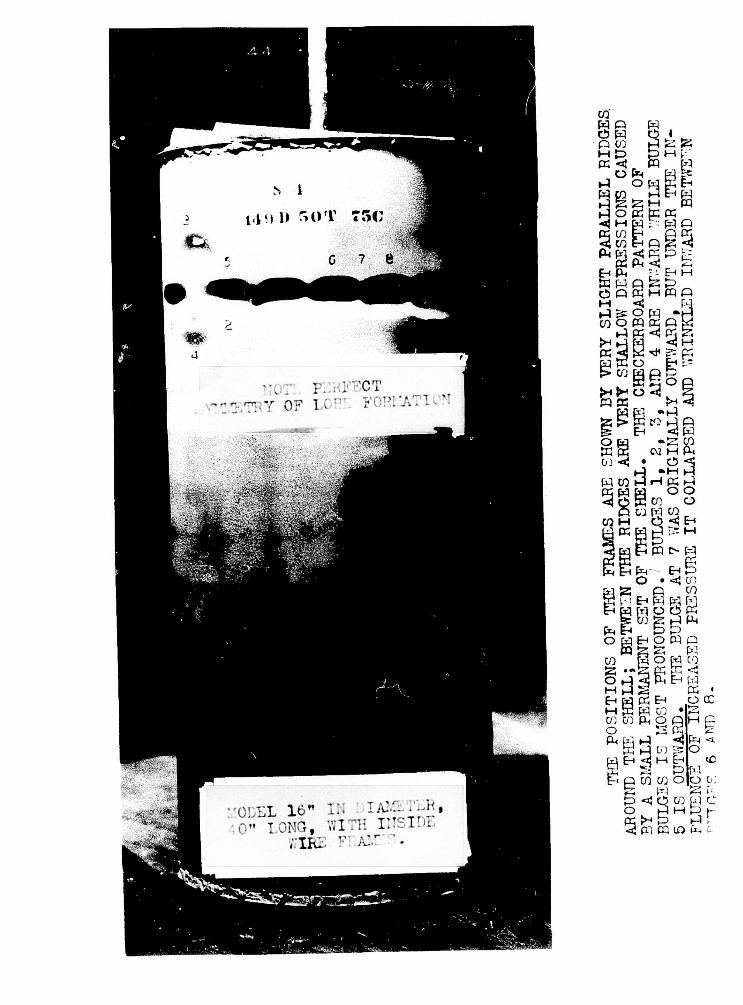
than one-fifth this amount. This means, in the case of a
model 16" In diameter and .05" shell thickness, that the
maximum radius cannot exceed the minimum by more than .025"
and that the variation in radius in about 2^", measured
circumferentially, cannot be greater than .005". This
requires extreme care in the construction of the models, as
well as accurate methods of measurement to determine the
influence of local out-of-roundness.
Tubing of the required dimensions was not obtain-
able; hence, it was necessary to fabricate the models by
rolling up a flat sheet of steel. For building the models,
a plunger V high and 1" thick was turned to exactly 16"
outside diameter. Since the shell thickness averaged .05",
a ring 2" high and 1" thick was turned to an inside diameter
of 16.10". This ring was made adjustable to accomodate
slight variations of shell thickness. Great care must be
used in fabricating the shell. A piece of material of the
same thickness as the shell is first used to set the rolls
for the required diameter. The shell is purposely cut about
a foot too long. Each end is then run through the rolls
for a distance of about 18", and the excess 6" length sawed
off. Since the rolls are accurately set and the ends are
already bent to the proper radius, the sheet can be run
through and will close at the ends at the proper diameter.
The outside ring is now fit snugly over the shell and the
IIIWI ll»l ' ^ ~ : :£

plunger is placed inside. By pushing both ring and plunger
along with a press and soldering the seam after the plunger
a very accurate model is formed. (See photographs).
RECORDING DEFORMATIONS
A measuring device was constructed for determining
the actual initial contour of the shell and its shape at
successive pressures as load was applied. (See photographs).
Measurements could be taken at 1 degree intervals at any
height desired. It was thus possible to plot the circumfer-
ence of the model on polar coordinate paper, greatly magni-
fying the irregularities. Longitudinal measurements could
also be made. (See sample data sheet),
APPLICATION OF FORMULAS
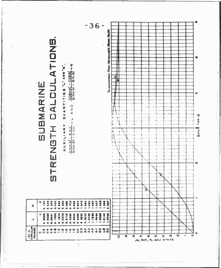
It is seen from equation (92) and from the
accompanying L and N curves, that for values of ocl of 6
or greater the collapsing pressure is independent of <xl
and therefore of the frame spacing. In the models used, with
r = 8" and t = .050" oC= 1.285/ ^fri « 2.03. This means
that for values of 1 greater than 3", formula (92) gives
constant collapsing pressures and, therefore, no longer holds.
Now it so happens that this value of al = 6 is
very near the desirable working range of 1 in a large sub-
marine, or about 36". It is, therefore, a very important
region. In this range, collapse likely occurs by instability,
Unfortunately, the values of P obtained by (96) do not check
■

well with experiment. The Germans had discovered this exper-
imentally, but had attributed the lack of agreement to the
fact that the models tested were not perfectly round. In
Hilfsbuch fur den Schiffbau, by Johow-Foerster, Berlin 1920,
is the following statement:
"Equation (3) (which is v Mises formula for collapse
without end load, Z.d.V.D.I. 1914 p.750, and is practically
equivalent to (96) for large values of n) gives values that
are too high for practical work, since the theoretical
assumptions cannot be fulfilled, owing to the unavoidable
departures from the circular form. According to experiments
conducted by the Germania Shipyward and by the Royal Dockyard
at Danzig one will be on the safe side when for plate thick-
nesses up to 5 mm., (or .197"), P as found by equation (3)
is multiplied by the coeff_cient 0.J+; for thicknesses of 5-7
mm, (or .197"-.276"), by 0.5; and for those above 7 mm.,
(or .276"), by 0.6". And again, "even though in actual
practice the preliminary conditions of the theory cannot
be fulfilled and auite marked deviations from the circular
form occur, nevertheless it is found that the number of
bulges obtained from equation (3) corresponds in reality very
well with the theory and that it gives very good values
also for the collapsing pressure when the above mentioned
coefficients are used." All this assumes, of course, that
the limit of proportionality has not been exceeded.
Our experiments show that this is good agreement
between the observed length of the bulges and the computed
length obtained by dividing the circumference by the value
of n that makes the value of P in (96) a minimum. The
■SM*»J. .■■ ■■■.■

8
shell thickness of our 16" models was 0.O50" or 1.27 mm.
For this thickness the constant multiplier 0.4 is Indicated.
However, these models are constructed with the same degree
of accuracy as the full scale submarine whose shell thickness
is 0.588" or lri mm., and here the above rule gives 0.6 as the
constant. It seems reasonable to assume that this constant
is not a function of the thickness itself, but rather of the
accuracy with which a shell of that thickness can be fabri-
cated .
Be that as it may, the use of any constant multi-
plier less than unity assumes that the theoretical collapsing
pressure is above the experimental. Table I (next page)
is taken from data sheet No. 3, showing the actual and
theoretical collapsing pressures. (Note: The notation employed
In numbering the models is as follows: S X are open head
models, in which the measuring device could be used and which
are knovm to be more accurately constructed. All other models
are closed at both ends and nothing is certain about their
departures from circular form. The second term, 179D, 154D>
etc., means that the frame spacing is 0.179 and 0.154 times
the diameter respectively, which for D = 16" gives 2.864"
and 2.473". The term 50T refers to the approximate thickness
and means that the thickness is about 0.050". 51C, 99U,
111 1, etc., gives the depth and type of frame, C referring
to circular frames, U to channels and 1 to the cut I beams,
while the 51, 99, etc., mean that the depth of the frame is
5.1 and 9.9 times the wall thickness. The numbers 1,2,3,
following, differentiate identical models.)
.

Lbs. per sq. in Ratio
Model Uni ed
mpport- lencth
38.7
Exp ' t P
Theoreti For. (96)
cal P For. (92)
Exp' t Calc. (96)
.68
Exp11 Calc . (92)
SIII 6A 22 32.3
" 6B it 27 31.4 .86
" 6C it 28 30.1 .93
w 2 16 61 78.1 .78
" 5-46D50T1 8.75 65 72.1 .90
" 375D50T1 6 107 128.8 .83 ^-X £-
SV 179D50T51C1 2.739 122 2A0 129.1 .51 .95
SIV " " 75C 2.676 1U 292 9-4.4 .39 1.21
SV " " ii it 96 218 87.2 .44 1.10
ii ii 150 316 129.9 .47 1.15
SX 15AD50T5OC1 2.3A8 180 379 167.0 .47 1.08 -1 /-v 0
11 it " " 2 it 170 370 164.4 .46 1.03
SV 1A9D50T51C 2.259 115 272 110.8 .42 1.04
.98 SX " " Cl n 115 290 117.9 .40
SX " " C2 ti 162 386 158.9 .42 1.02
tl It " C3 ii 170 394 160.6 .43 l.Oo
SIV " ti 75C 2.196 125 350 85.0 .36 1.47 1^1 J» 1
M II ii 127 355 85.6 .36 1.48 SVIII
sv ,. n "
SX 15AD50T99U1
n
2.185
110
170
256
343
82.9
172.4
.43
.50
1 33
.99
.96
.91 SX " ft n
" U2
" U3
n
n
165
155
339
339
171.1
171.1
.49
.46

10
"We see that for models with a fairly long un-
supported length (in excess of one diameter) formula (96),
instead of giving values which are too high as predicted in
Schiffbau, gives values which are too low by 50 per cent,
even though the model is undoubtedly as irregular or even
more irregular than the shorter lengths which are supposed
to fail far below the theoretical value because of their
irregularities. To get the correct collapsing pressure here,
it would be necessary to multiply by a factor of 2 instead
of 0.6. For shorter lengths of unsupported shell, (from
2.7^" to 2.18"), a factor of 0.^ to 0,5 would appear to
give the more reliable results, although it is quite
certain that the proportional limit has been exceeded. In
which case (96) is inapolicable.
It would seem, therefore, that formula (96) holds
for only a comparatively short range within which a specific
constant must be determined by experiment. This constant
is likely a function rather of the length of unsupported
shell than of the thickness of shell involved, assuming the
same percentage accuracy in fabrication. Further tests
are needed to determine the effect of unsupported length
upon the constant required to make the actual collapsing
pressure check with the theoretical.
It may or may not be significant that the constant
0.4. seems to give approximate collapsing pressures according
to (96) even though the correct collapsing pressure is given
directly by (92) . If at tne pressure at which failure
occurs, the stresses are such that the modulus has changed
from E within the proportional range to 0.4- E Just before

11
yield, then failure may be occurring by instability, and
at the yield point the two formulae may merge into each other.
This seems the more probable since the failure on all models
appear identical in pattern whether the stresses calculated
by (82) were above or below the proportional limit. This
explanation, however, cannot account for a constant multiplier
greater than unity in the longer models.
Table I shows also how values computed by formula
(92) compare with experiment. The models ...75C, in which
the frames were simply one turn of (.148" diameter) iron
wire, give theoretical values which are considerably below
the experimental, being as much as 47^ and 4-8^ below in
the case of the shorter frame spacing. This is likely
because the area of the frames is very great, although the
theory pretends to hold for areas which approach infinity,
(solid bulkhead). For all smaller frames, especially the
channels, (92) gives very accurate values with a maximum
deviation of 9 per cent for all models tested and a mean
deviation of less than 4 per cent. This is undoubtedly as
great as the accuracy with which the yield point of the
material was determined. It must, however, be borne in
mind that this formula has been checked for only a small
range of values of frame spacing and scantlings, and that
conclusions cannot be too readily formed as to its applicability
under other combinations. The above variation for heavy
frames would Justify caution. Further tests should be made
to determine the limits of applicability of the formula.
. .

12
SCALE EFFECT
No scale effect is predicted by the theory and
our results thus far seem to bear this out.
STRENGTH OF FRAMES
When a simple circular ring is subjected to uniform,
external pressure, collapse occurs by instability and the
generally accepted formula due to M. Levy (Jour.d.math,
pure et appl., Liouville, Ser. 3 Vol. X, (1884.) p.5) is
where P is the pressure at which frame buckles,
E is Young's modulus,
I is the moment of inertia of
cross-section of frame,
r is the radius of frame to neutral axis.
This formula is usually attributed to Foppl. In the 1900
edition of Foppl1s "Festigkeitslehre" it is given in the
slightly altered form: p _ 4J£I Pk r3
Formula (36) can be extended to Include the
cylindrical tube of Infinite length if the proper assumptions
are made concerning the resistance to change of curvature
caused by adjoining portions. When the value of I for a
rectangular cross-section of unit length is taken, (I = 1/12 t.l)
equation (36) becomes p - E (t)3 Pk ~ 4 r3
where t = thickness of frame measured radially, and if we
take into consideration the resistance to the change of curva-

13
ture offered by the adjoining portions, we get (see Bryan,
Proc. Carab. Phil. Soc. Vol. VI, (1888) p. 287)
K = -3^-7 f ^3 = 66,700,000 Q* k mz - 1 A. (r)3 ' * (d)3
where d = diameter of ring, and m = Poisson's ratio.
The empirical values obtained experimentally by
Carman and Carr (Univ. Illinois Engr. Expt. Sta. Bull, No.
5, 1906) and Stewart (Am. Soc. Mech. Engrs., (1906) p. 795)
are
Pk = 50,200,000 ^3
which is about 25 per cent lower, yet of identical form
for variations of t and d. The decrease in actual collapsing
pressure in the latter formula is attributed to irregularities
in material and workmanship.
It seems, therefore, that if a tube fails by
instability, the method of failure is identical with that
of a frame or ring which fails by instability. If, then,
the pressure on the shell is sufficient to cause its collapse
by instability, while at the same time the load transmitted
by the shell to the frame exceeds the frame's critical
buckling pressure, the shell and the frame will both collapse
at that pressure. However, if the frames are made stronger,
the shell will collapse by bulging between them, after which
the frames will receive the entire load. They will then
collapse by instability if this total load exceeds their
critical buckling pressure. Prof. Hovgaard (Memo. 83 to
Bu. of C & R, p 2) says that "the formula applies when frames
are fitted, provided they are of uniform construction and
evenly spaced, in which case they may be assumed to form an
integral part of the shell and their moment of inertia may
1

u
be supposed to be evenly distributed, each frame being
considered in conjunction with a length of one frame space
of the shell plating". This statement, of course, has no
bearing upon the case where the frames are so strong that
the shell fails first by bulging. The frames then have
the effect of shortening the tube and the collapsing pressure
must be computed for a length of tub equivalent to the
unsupported length betv/een frames. . greater frame strength
has no influence on the strength of the tube providing the
spacing is sufficiently great to insure collapse by instability
This was tested with models 6" in diameter and 14.5"
long. (See data sheet No. 1, series II, 2 to 10 Bl and
table I). It was found that a single turn of (.102" diam-
meter) wire at the center of the model caused as high a
collapsing pressure as a solid bulkhead at that point. The
same results were obtained for models 0=6", L = 8.5".
TABLE II
Models 14-.5" Long
Model Frame Collapsing Thickness Pressure con SII Pressure
Actual verted to standard t = .0250
2A 16 G., D = .050 36.9 .0238 40.9 5A2 12 G., D = .0795 38.2 .0250 38.2 3A 10 G., D = .102 51.1 .0245 53.2 AA 7 G., D = .U75 48.5 .0240 52.7 4B 7 G., D = .U75 55.1 .0252 54.0 10A Bulkhead 46.3 .0230 55.2 10A1 n 48.9 .0230 58.6 10B1 11 48.9 .0240 53.2 10B n 46.7 .0234 54.0 2X 16 G., D = .050 57.8 .0235 65.8 3X 10 G., D = .102 68.4 .0235 78.1 4X 7 G., D = .1475 72.0 .0240 78.4 10X Bulkhe ad 69.8 .0236 78.4

15
STRENGTH OF ARCHES
The formula for collapse of circular frames can
be extended to the collapse of pin-Jointed arches; that is,
to circular frames which are constrained to fail in more
than two lobes. The actual development of the formula gives
(See Applied Elasticity, Timoshenko and Lessells, p. 246)
\- _ (n" -DEI - [( f)' - x] E I 1363 r~ L- v ' j r"
where n is the number of lobes into which the frame collapses
or n = -y.
When n = 2, which is the case for the free circular
frame, we get formula (36) mentioned above. However, if the
frame is held rigid at two points, leaving a free arch sub-
tending an angle 6 at the center of the frame, then the angle
6 is fixed and we can use (36'). If the ends of the frame
be considered fixed or encastre, by analogy to EulerTs
formula for beams with fixed ends, the length 1 considered
for the pin-ended rod must be replaced by 2/3 1, since
1 ~ v6 , 6 must be replaced by 2/3 B and (36') becomes
\- [<f)2-x] E I [36 ']
For 9 = 180, (36') gives the coefficient 3 which makes it
identical with (36), but when substituted in (36") the
coefficient becomes 8. The values of the coefficient to be
used for various angles are given in the table III below.
Table III
Values of Calculated Coefficient for Arches
Angle 9 »degrees Pin-Jointed Fixed ends
180 3 8 135 6.1 15 120 8 19.25 90 15 60 35
35 80

16
These values all assume, of course, that the pro-
portional limit of the material has not been exceeded, and
also that there is no eccentric loading due to local stresses
transmitted to the frame hy the shell in the process of
collapse.
According to the above table, if a frame with an
unsupported arc of 180 degrees falls due to Instability by
formula (36')> that same frame might easily be strong enough
if only 135 degrees of arc were left unsupported. It fre-
quently happens in submarine construction that the bottom of
the strength hull is stiffened by rigid tank structures
reaching up above the bilges and often above the axis of the
vessel, leaving a relatively slender arch-like frame at the
top. It is desirable, therefore, to know how much dependence
can be placed on formula (36') in actual practice.
Accordingly, a series of five models were con-
structed with heavy floors which made the frames rigid for
arcs of 90 degrees, 135 degrees, 180 degrees, 225 degrees,
and 270 degrees. The frames were turned on the lathe and
made to simulate the shipbuilding channel C-109 (6" x 3^" x 15.3
lbs.). They were computed by formula (36) to fall at 150
pounds pressure. They were first used in models SX, 154-D50T99U1,
2,3. (See data sheet No. 3 and Table I). The computed
buckling pressures by (92) were 172.4, 171.1, and 171.1
pounds, respectively, while the actual buckling pressures
were 170, 165, and 155 pounds. The last named model had a
variation in radius greater than that allowed, being about
0.020" in an arc of 30 degrees. In each of these models, the
frames failed with the shell, as was to be expected, since by

17
(36) they were computed to fail at 150 pounds. These same
frames were used In the series of five models. If the
constant 3 in equation (36) changes to 6.1 for 135 degrees
and to 15 for 90 degrees unsupported arc, the frames should
surely be strong enough to hold even after the shell has
failed completely. In the latter case, the frames should
hold 2,250 pounds pressure, which, of course, is absurd
since this load gives rise to stresses exceeding the yield
point of the material. The models were tested with the
results shown in Table TV.
TABLE IV
Unsupported arc Collapsing pressure
Shell Theory Exp't
360 172.4 170
360° 171.1 165
270° 177.5 165
270° 183.1 180
225° 205.0 175
180° 200.7 160
Frame Theory Exp't
150 Failed n with
shell M n
11 n
II n
II n
300 n
2,250 n
135° 173.8 165
90° 188.3 185
It is seen that decreasing the length of unsupported
arc of the frames does not noticeably affect their buckling
pressure. This may be due to the fact that because of
eccentric loading at the bulges, the flanges are bent out of
shape and the frames fail by local crippling rather than
through pure instability. Whatever the explanation, it is
obvious that the constant in (36) cannot be increased with
safety when applied to frames in a submarine hull
—■5" \..- ■'■: ■■ •,.■,,„ f ■■ ,-,;,,, ..-s.,-...,..., .^ar. • i ,, .■-,«>•■«;..•, .-,-,, --■■
I

18
All that has been said for inside frames holds
equally well for outside frames providing that by welding,
or possibly by riveting, the frames become an integral part
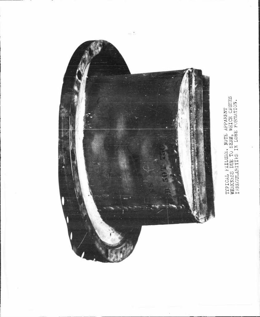
of the shell. Only one model has been tested with outside
frames. These frames were made to the same scale from an
I beam (B17 Am. Standard Section) with half of one outer
flange removed. They were computed by (36) to fail at
209.1 pounds pressure and the shell by (92) to fail at 183.4
pounds. The frames were spot-welded to the shell at one-
half inch intervals, staggered on the two sides of the flange.
The first bulge appeared in the shell at 160 pounds pressure
and we define this as the collapsing pressure of the model.
However, it was possible to increase the pressure to 180
pounds without complete collapse. Many new bulges were
formed, but the frames did not fail, although there were
indications that the flanges were becoming bent out of shape.
Due to leaking of the model, greater pressures could not be
applied.
The behavior of this model was identical with the
large model tested at the Portsmouth Navy Yard. This latter
was 0.443 scale of a full sized submarine, or 86.6"
outside diameter, and the scantlings were 5.379 scale of
our 16.1 outside diameter model Just mentioned. The Portsmouth
model was much more irregular than the small models or the
full-size ships. It is interesting to observe that, as the
result of previous model tests, it was possible to predict
the point of failure as well as the collapsing pressure.
The first bulge occurred at 140 pounds pressure at the most
■ . ' , -

19
irregular region. Three other bulges appeared at 150
pounds. At 165 pounds pressure, four other bulges appeared
almost simultaneously and the leaking became so excessive
that the test had to be discontinued. There is, however,
one notable difference between the Portsmouth model and our
own. While our model had a shell whose yield point was
32,000 pounds per square inch and formula (92) was determin-
ative, the larger model was made of material with a yield
point of 36,000 pounds per square inch and by (82) the stress
was still within the proportional limit. The failing press-
ure was predicted correctly by (96) when r was used equal
to the radius of curvature of the flattened portion at which
failure first occurred and the answer was multiplied by 0.6
according to the rule given in Schiffbau. However, because
of the eccentric loading at the flattened portion, the stress-
es are likely much higher than given by (82), and may easily
be at or near the yield point of the material.
Comparison of these two models gives no indication
so far that there is p.ny scale effect and shows that 16"
models can be relied upon to give reliable results as long
as the scantlings can be made to duplicate the scantlings
of the larger models in geometrical forms. However, material
of identical physical properties must be used.
NUMBER OF FRAMES
When designing models for testing, the question
at once arises as to the effect of the length of the model.
Will the collapsing pressure be the same for a model containing
two or three frames as for a model of the same scantlings con-
taining twelve or fifteen frames? The number of frames does
not appear in either (92) or (96) and the assumption is that
.

20
they are unimportant as long as the frame spacing remains
constant. To test this, a model (S IV U9D 50T 75C) 38.7"
long was constructed, containing 16 wire frames. It failed
at 125 pounds pressure. After the failed portion was cut
away, we had left a model 10" long, containing 4 frames.
This, when tested, failed at 127 pounds pressure. The measured
thlclfness for the shorter model was 0.0488" as compared with
0.0485" for the longer model, hence it should have failed
at slightly higher pressure. This shows that a model con-
taining three or four frames can be relied upon to give as
reliable results as a model with a larger number of frames.
One precaution, however, is necessary. Since the heads of
the models are bulkheads, or frames of infinite strength,
the shell by (92) is weakest at the end spaces. To rule
out the effect of these bulkheads, the end spaces must be
made shorter, thus forcing the shell to fall between the
frames. In all our models after S III 154F, the end spaces
were made about two-thirds of the frame spacing.
EFFECT OF LONGITUDIIIAL STRAPS
An Investigation was made to determine the effect
of longitudinal straps (equivalent to two thicknesses of
shell) on lobe formation. It has always been felt that if
the shell were strengthened by longitudinal straps, such as
seam straps, the lobes, or bulges, would be hindered in their
regular formation, their length would thereby be decreased
and, therefore, by (96), the collapsing pressure would be
considerably Increased. This was the same assumption which
made it seem reasonable to expect that frames would be
strengthened by decreasing the length of unsupported arc.
.

21
Tests were made with models 6" in diameter. We
believed these models to be fairly accurate, but no method
was then available for determining the actual contour of
the surface. In the first model, (SII, IE), solder only was
used at the seam. In the other models, (SII, 1G-9N, see
data sheet No. 1 and Table V), the seam was not only soldered
but was supported by a butt-strap in addition. These straps
had the following widths: lA", 1", 2", 4", 6", 9 1/2"
(semi-circumference), 12 1/2" (2/3 circumference), M 1/2"
(3/4 circumference), and 17" (.895 circumference). While
there was likely some additional strength due to the longi-
tudinals taking the end load, there was no marked increase
in collapsing pressure when proper corrections were made
for variations in shell thickness. It is certain that these
models, which had 14,.5" of unsupported shell length, failed
by instability. Formula (96) gives the collapsing pressure
as 36,7 pounds for a shell thickness 0.025", and the number
of lobes as 1*, This means that each lobe should be 4-.71"
long. For a lobe length less this value, - that is, for a
greater number of lobes, the collapsing pressure by (96) would
be increased. The length of shell unsupported by the butt-
strap in 9N was 1.85" and this should represent the maximum
length of lobe. Since the circumference was 18.85", n
would equal 10 and the collapsing pressure by (96) would be
200 pounds. This value, however, is more than 500 per cent
greater than the actual collapsing pressure. (See Table V).
The collapsing pressure of 9N is 16 per cent above the mean,
but IB failed at a still higher pressure and it had only a 1«
butt-strap. Likely 9N and IB were more nearly circular and
therefore failed at the theoretical collapsing pressure, while
-

models IE, 5A1, 8A, and 8B were more irregular which caused
their lower collapsing pressures. This is even more probable
when we consider that IE, which had solder only at the ceam,
failed at a higher pressure than 8A and 8B which had straps
equal to a serai-circumference. We must conclude, then,
that the collapsing pressure cannot be materially increased
by using longitudinals to break up the lobe formation.
However, we cannot be too certain of this when the unsupported
length of shell is less than the length of one lobe, since the
one model in which this condition existed may have been
defective. Further tests are contemplated with larger and
more accurate models, in which the longitudinals will simu-
late those used in submarine construction.
TABLE V
Effect of Longitudinal Straps
Model Seam Sll c support
IE Solder onl IG 1/4' ' strap 1A 1' ' strap IB 1' ' strap 5 Al 2' ' strap 6A 4' ' strap 7A 6' ' strap 8A 9i ' ' strap 8B " i 1 strap 9A 12i' ' strap 9G uV ' strap 9N 17 ' ' strap
Falling Shell P converted P. lbs. Thickness to t =.0250
30.2 .0251 29.8 28.A .0236 32.1 32.9 .0252 32.1 38.7 .0248 39.3 29.8 .0255 28.5 34.7 .0250 34.7 34.7 .0253 36.8 25.8 .0235 29.6 26.7 .0242 28.5 34.7 .0250 34.7 32.0 .0243 33.9 36.5 .0243 38.8
- ■■.■....

23
REFERENCES
Werft und Reederei 1920, heft 8, p. 163 ff.
Proc. Inst. Civ. Eng. Vol. XLVI, 1895, p. 225.
Phil. Trans., Vol. 148, 1858, p. 389.
Phil. Trans. Royal Soc. Vol. 213, 1914, p. 187.
Z. d. V. D. I., 1914, P- 750.
Untersuchungen über Knickfestigkeit, Mitteilungen über Forschungsarbeiten, heft 81, 1910.
Hilfsbuch fur den Schiffbau, - Johow-Foerster 1920.
Jour. d. Math, pure et appl. Liouville, Ser. 3, Vol. X, p. 5, I884.
Foppl. Festigkeitslehre.
Proc. Carab. Phil. Soc. Vol. VI, 1888, p. 287.
Univ. III Engr. Expt. Sta. Bull. No. 5, 1906.
Am. Soc. Mech. Engrs., 1906, p. 795.
Prof. Hovgaard Memo. 83 to Bu. of C & R.
Applied Elasticity, Timoshenko and Lesseis, p. 246.

2A
Supplement, U.S. Experimental Model Basin Report 262 Progress Report on Tests of Model Pressure Vessels.
CLASSIFICATION OF MODELS AND IDENTIFICATION NUMBERS
Classification:
Series Description
I 6 inch models (internal diameter - 6 in.). II Plain. One inter-frame space. III 16 inch models with an open head in nearly all cases
and one Inter-frame space determined either by two heavy frames near the ends or, as in a few early models, by the ends themselves. ("Inter- frame" refers to the unsupported shell between tv.'o adjacent frames or bulkheads).
III-L Same as Series III except for the use of lap seams instead of butt seams»
IV 16 inch models, closed heads. Many frames. 38.7" long, V 16 inch models, closed heads. Many frames. 15 in.long, VI 6 inch models. Many frames. 14-5 inch long. VII 6 inch models. 5 frames, 4 inter-frame spaces. VIII Portions of models of Series IV. IX 6 inch models. 5 outside wire frames, 4 inter-frame
spaces. X 16 inch models, open heads. Two inter-frame spaces
determined by three inside frames. XI 6 inch models. 3 frames, 2 inter-frame spaces. XII 16 inch models, open heads. Tv/o inter-frame spaces
determined by three outside frames. XIII 6 inch models. 2 frames, 1 inter-frame space.
Identification Numbers:
The system used, discussed on page 8 of the report, is best described by an example. The identification number
S III 546 D 50 T 1
signifies:
(a) Series III of the above classification. (b> Unsupported length (distance between the inner sur-
faces of two adjacent frames or bulkheads) is 0.546 times the internal diameter.
(c) Nominal thickness is 0.050 inches. (d) The model is first of a group of identical models.
■ ■■ ■

25
U.S. E.M.B. Report No. 262 (Supplement) Sheet 2
In some other identification numbers there were additional symbols inserted after "T". They are described in the following examples:
In S X 149 D 50 T 51 C 3 the 51 C signifies that
the depth of frame is 5.1 times the nominal shell thickness,
and that the frame is of circular cross section. The symbols
for frames of other cross sections are
U Channel.
I I-beam.
L Angle.
I I-beam with half of outer flange removed.
In S X 15A D 50 T 99 UF 135 C 1 the latter part
signifies that the depth of the channel frame is 9.9 times
the nominal shell thickness, and a flat of 135 circumfer-
ential extension is attached to the frame. The usual flat
Is a circular sector; the "c" after 135 signifies that this
particular flat was a piece of a circular ring.
In S XII 154 D 50 T 111 I 6 LKT 1 the 6 LKT
signifies 6 longitudinal straps, a keel, and a tank top.
■

26
Model Pressure Vessels
CLASSIFICATION
Revised July 1933
Type I All 6 in. models (internal diameter = 6 in.)
II 16 in. models with closed heads.
Ill 16 in. models with open heads and one inter-frame space determined by two heavy frames near the ends. ("Inter-frame space" refers to the unsupported shell between two adjacent frames or bulkheads).
IV 16 in. models with open heads and two interframe spaces determined by three inside frames.
V 16 in. models with open heads and two inter-frame spaces determined by three outside frames.
VI 16 in. models with open heads and two inter-frame spaces determined by two pairs of frames of un- equal size.
Subgroups
III-L Models of Type III with lap seams instead of the
usual butt seams.
IV-F Models of Type IV with flats attached to the frames.
V-S Models of Type V with special features of a submarine
pressure hull.
Comparison of Revised and Previous Classifications
Note: The previous classification of models by "Series" is described in a supplement to U.S. E.M.B. Report No. 262, June, 1930
Type I comprises all of the seven previous Series: I, II, VI, VII, IX, XI, XIII.
Type II comprises the previous Series: IV, V, VIII, part of III.
Type III comprises practically all of the previous Series III; Type III-L corresponds to the previous Series III-L.
Type IV corresponds to the previous Series X.
Type V corresponds to the previous Series XII.


COLLAPSE OF SUBMARINE MODELS DATA SHEET NO.3

- 3^
o
Ü 2
a •-I
re
a < a
o -a

MEASURING APPARATUS
HEAD FOR COMPRESSION TANK.
HEAD FOR MODEL
SHELL OF MODEL
BOTTOM OF MODEL

-. .
36
si
hi Z
d
ID D U3
Z g <
j
Ü J ct Ü
(D Z UJ K H m
2 i
■33 o? U «ft
9ft
z <
>
o 2
?l
«»oöoobööb — — -■ — — — — •
•TiTiTrsTsTaTJiTiii
oöödd--;--~.>lWs«»«,*^«Js3 9

>H J H
• » CO M
< CU rt ex [x. <c
v-l CO Ö >—• S5 a < s a < o
J^v w •< • d O >-( H O M CO ^ VH Sa » 1—1 CO M
t-H O Ä l-t E-i W > >-( W g: S A
< t-H ^ Ä pq tx. HJ Q ^ O fe l-d a 0 ä
CO tu W O Ä [X
^ 3 fü ^ £ ^ 9 ►J Pu M M O < E-i J OH -< 5
Ä cq J tH •^ 3 O ^1 EH M ir-l CL. O « ^^5 £-t<wQ


42
,,., -'* ^.
SX 154 1) r^O'V <)*)ITI. ,.

MODEL WITH uUTSIDE FRAMES SPüT ^^^ T^T^L-'L.
FRAMES ARE IN SHAPE OF I BEAM «Piu^n^ q?rN S FLANGE REMOVED. NUTE THAT FRALIES SHu.,ED Nu SIoN üF
FAILURE.
(XI W • O'J la £3 O
8H -a; n 2". O &H W < « w g < o w D-. M O cu tc fc < w w s o < 1-1 w CO Z
EH D
ö o
j M M M P EH <4 Q n
CO < j co t5 «J tx) P o fe o M ^ W a. ^ cr;
c^ ^£ HH

CO pM
w S ^ ^ tu W tq en
M O Q ^
.>o z <; ^ -3 H
Q = 3 «^O

-CD O
III 5; i-t o
CO M O K
to C5 fc o fT-
faSpk O «L
ÜT cn

Armed Services Technical Informatiom Hgency Reproduced by
DOCUMENT SERVICE CENTER KNOTT BUILDING, DAYTON, 2, OHIO
This document is the property of the United States Government. It is furmished for the du- ration of the contract and shall be returned when no longer required, or upona recall by ASTIA to the following address: Armed Services Technical Informsation Agency, Document Service Center, Knott Building, Dayton 2, Ohio.
NOTICE: WHEN GOVERNMENT OR OTHER DRAWINGS, SPECIFICATIONS OR OTHER DATA ARE USED FOR ANY PURPOSE OTHER THAN IN CONNECTION WITH A DEFINITELY RELATED GOVERNMENT PROCUREMENT OPERATION, THE U. S. GOVERNMENT THEREBY INCURS NO RESPONSIBILITY, NOR ANY OBLIGATION WHATSOEVER; AND THE FACT THAT THE GOVERNMENT MAY HAVE FORMULATED, FURNISHED, OR IN ANY WAY SUPPLIED THE SAID DRAWINGS, SPECIFICATIONS, OR OTHER DATA IS NOT TO BE REGAKDED BY IMPLICATION OR OTHERWISE AS IN ANY MANNER LICENSING THE HOLDER OR ANY OTHER PERSON OR CORPORATION, OR CONVEYING ANY RIGHTS OR PERMISSION TO MANUFACTURE, USE OR SELL ANY PATENTED INVENTION THAT MAY IN ANY WAY BE RELATED THERETO.
UNCLASSIF