directional instability of rear caster wheelchairs€¦ · 2 journal of rehabilitation research and...
TRANSCRIPT

4\VrtifffN VeteransAdministration
Journal of Rehabilitation Researchand Development Vol . 25 No.3Pages 1—18
Directional instability of rear caster wheelchairs
TIMOTHY J . COLLINS, MS, and JAMES J . KAUZLARICH, PhDUniversity of Virginia Rehabilitation Engineering Center, P .O. Box 3368, University Station,Charlottesville, Virginia 22903
Abstract—Although less common than conventionalfront caster wheelchairs, rear caster wheelchairs are stillin use for several reasons . Many people find manual rearcaster wheelchairs easier to maneuver indoors at slowspeeds . This is especially true when the user attempts tomaneuver the wheelchair very close to an object, such asa table . Electric wheelchairs often have rear casters toaccommodate for front wheel drive . If the larger drivewheels are located at the front of the wheelchair,obstacles such as a curb can be negotiated much moreeasily . However, a major disadvantage of rear casterwheelchairs is that they are generally known to bedirectionally unstable, especially at high forward speeds.This paper presents the results of a study to determinespecific measures that can be employed to improve thestability of this type of wheelchair.
The instability of rear caster wheelchairs is due prima-rily to road forces that act on the tires when thewheelchair is displaced from its line of motion by a bumpor other irregularity in the road surface . The paperdiscusses the experimental investigation of these roadforces as well as a dynamic model used to study theinstability problem . The results of a computer simulationprogram used to perform a parametric study of differentdesign variables are discussed . Center of gravity position,caster trail distance, and caster pin friction are found tohave a dominant influence on rear caster wheelchair
This work was supported by the National Institute on Disability andRehabilitation Research, Grant #G00-8300-72.
Tim Collins is presently an engineer at NASA Langley Research Centerin Hampton, Virginia.Address all correspondence to : James J . Kauzlarich, PhD, University ofVirginia Rehabilitation Engineering Center, PO Box 3368, UniversityStation, Charlottesville, VA 22903 .
directional control . Several simple but significant designrecommendations are presented.
Key words : center of gravity, directional instability, frontwheel drive, rear caster wheelchair.
INTRODUCTION
The problem of controlling an unstable vehicle isnot new. For example, it has been known for sometime that aircraft equipped with a castered tailwheelexperience steering difficulty while taxiing . Theseplanes require tail rudder control and wheel brakingin order to maintain a straight path . Wheelchairsthat have rear castered or rear pivoting wheelsexperience a very similar problem . However, aircraftand wheelchairs with pivoting wheels in front of thecenter of gravity are always directionally stable upto very high speeds.
There are several motivations for studying thedirectional control problem associated with rearcaster wheelchairs . Although less popular thanconventional front caster wheelchairs, rear casterwheelchairs have several inherent advantages . Elec-tric wheelchairs often use rear casters because of theease with which obstacles such as a curb can benegotiated. Other considerations sometimes makerear casters desirable for manual wheelchairs . Forexample, rear caster manual wheelchairs are gener-ally easier to maneuver close to an object, such as acounter or table . Aside from these reasons, some

2
Journal of Rehabilitation Research and Development Vol . 25 No . 3 Summer 1988
Figure 1.
A typical manual rear caster wheelchair.
users purchase a rear caster wheelchair simplybecause it is the type they are accustomed to.
Steering instabilities associated with rear castersmust be compensated for in order for the user tomaintain a straight path. Unstable electric wheel-chairs require much more manipulation of thejoystick . Unstable manual wheelchairs require addi-tional physical exertion that some users may beunable to supply. When operated at high speeds oron uneven ground, rear caster wheelchairs are oftenuncontrollable and may become dangerous . Forthese reasons, a potential user should have anunderstanding of the directional instability of rearcaster wheelchairs . Figure 1 shows a typical manualrear caster wheelchair.
PROBLEM DESCRIPTION
Directional stability is generally defined as theability of a moving vehicle to stabilize its motionagainst external disturbances . A fundamental de-scription of the control problem associated with rearcaster wheelchairs was published in 1985 byKauzlarich and Thacker (6) . They showed that whena wheelchair is displaced from its line of motion bya jolting force, such as a bump in the road, itexperiences a twisting moment about the center of
gravity . This moment is due to lateral road forcesthat develop at the tire-road interface.
Figure 2 shows a rear caster wheelchair that hasbeen suddenly displaced from the intended directionof motion by an angle, O . The lateral force on arolling tire is often referred to as a "corneringforce ." In Figure 2 the lateral road forces arelabeled F y. The distance s is measured perpendicu-larly from the 2 fixed wheels to the center of gravity.In this simplified analysis, the twisting momentproduced by the lateral road forces has a magnitudeof 2s 1Fy. Because the lateral road forces act aheadof the center of gravity for a rear caster wheelchair,the resulting moment M causes the wheelchair torotate even further away from the desired direc-tional heading. For this reason, the moment isreferred to as being directionally destabilizing.
It is clear from the simple model depicted inFigure 2 that reducing the distance s, will reduce thedestabilizing moment and thus will improve direc-tional control . Furthermore, it is clear that aknowledge of the lateral road force, F y , is necessaryfor a complete analysis of the instability problem.
This paper presents the results of experimentaltesting which was conducted for the purpose ofdeveloping a simple mathematical description oflateral wheelchair tire forces . A computer simulationmodel that incorporates this mathematical descrip-
Figure 2.
Destabilizing moment for rear caster wheelchair .
3
COLLINS and KAUZLARICH : Directional Instability of Rear Caster Wheelchairs
TRACTIVE FORCE (Fx )
(DIRECTION OF WHEEL HEADING)
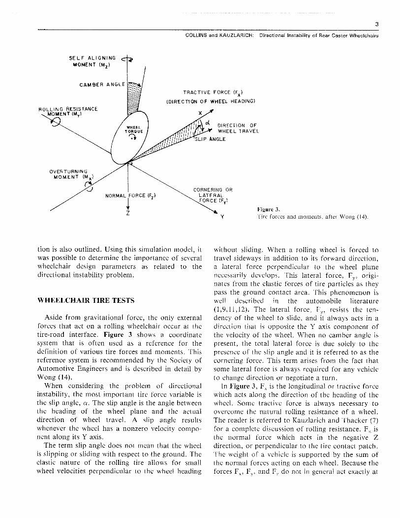
Figure 3.
Tire forces and moments, after Wong (14).
tion is also outlined . Using this simulation model, itwas possible to determine the importance of severalwheelchair design parameters as related to thedirectional instability problem.
WHEELCHAIR TIRE TESTS
Aside from gravitational force, the only externalforces that act on a rolling wheelchair occur at thetire-road interface . Figure 3 shows a coordinatesystem that is often used as a reference for thedefinition of various tire forces and moments . Thisreference system is recommended by the Society ofAutomotive Engineers and is described in detail byWong (14).
When considering the problem of directionalinstability, the most important tire force variable isthe slip angle, a . The slip angle is the angle betweenthe heading of the wheel plane and the actualdirection of wheel travel . A slip angle resultswhenever the wheel has a nonzero velocity compo-nent along its Y axis.
The term slip angle does not mean that the wheelis slipping or sliding with respect to the ground . Theelastic nature of the rolling tire allows for smallwheel velocities perpendicular to the wheel heading
without sliding . When a rolling wheel is forced totravel sideways in addition to its forward direction,a lateral force perpendicular to the wheel planenecessarily develops . This lateral force, F y, origi-nates from the elastic forces of tire particles as theypass the ground contact area . This phenomenon iswell described in the automobile literature(1,9,11,12) . The lateral force, F y, resists the ten-dency of the wheel to slide, and it always acts in adirection that is opposite the Y axis component ofthe velocity of the wheel . When no camber angle ispresent, the total lateral force is due solely to thepresence of the slip angle and it is referred to as thecornering force . This term arises from the fact thatsome lateral force is always required for any vehicleto change direction or negotiate a turn.
In Figure 3, FX is the longitudinal or tractive forcewhich acts along the direction of the heading of thewheel . Some tractive force is always necessary toovercome the natural rolling resistance of a wheel.The reader is referred to Kauzlarich and Thacker (7)for a complete discussion of rolling resistance . Fz isthe normal force which acts in the negative Zdirection, or perpendicular to the tire contact patch.The weight of a vehicle is supported by the sum ofthe normal forces acting on each wheel . Because theforces F 7, Fy , and F, do not in general act exactly at

4
Journal of Rehabilitation Research and Development Vol . 25 No . 3 Summer 1988
250
0
200 -
Z
wUceo
LIMIT OF ROAD ADHESION
CONSTANT NORMAL FORCEFZ = 300N (67LBF)
LL.03Jv
wU
0L=
O
20 wzo:0v
-1050
150-
r0
2
3
4
5
6
SLIP ANGLE a
(DEG)
Figure 4.Typical cornering force versus slip anglecurve at constant normal force.
80
the origin as shown in Figure 3, they create 3moments that act on a rolling tire . These momentsare small for wheelchair tires and can be ignored fora first order analysis of wheelchair motion.
Because the lateral tire force, Fy , as shown inFigure 2 and Figure 3 is inevitably responsible forthe deviation of a vehicle from a direct course, it isalmost universally regarded as the most importantof all the tire forces and moments (9) . When avehicle is constrained to make only moderate coursechanges on a level surface, it is found that theprimary variables that affect cornering force arenormal force and slip angle . This assertion iswell-supported by extensive tests that have beenconducted on automobile tires (1,10,11,14) and bytreadmill tests performed using wheelchair tires (2).
As part of the research reported in this paper,several different wheelchair tires were examinedusing a test cart and a treadmill . A load cellmounted alongside the treadmill was used to mea-sure the cornering force, Fy , exerted on a fixedwheel that had been turned to some known slipangle with respect to the motion of the treadmillbelt. This testing was carried out for a range ofnormal forces, F,, at the tire-belt interface . Bothpneumatic and solid rubber tires were considered.The details of the test cart and treadmill apparatusused to investigate wheelchair tire forces are con-tained in reference (2) and will not be presentedhere .
Figure 4 illustrates a typical plot of corneringforce as a function of slip angle for a representativewheelchair tire (in this case a solid rubber tire) . Forsmall slip angles, the cornering force increaseslinearly with an increase in slip angle . For slip angleslarger than approximately 2 degrees, the corneringforce begins to increase at a lower rate . Thecornering force reaches a maximum value as itapproaches the limit of road adhesion. At this point,the tire begins to slide laterally.
Using treadmill data for a range of slip angles andtest cart loads makes it possible to construct afamily of cornering force curves for a particularwheelchair tire . Figure 5 shows such a family ofcurves for the same solid rubber tire represented inFigure 4 . Using an experimentally determined set ofcurves like those in Figure 5, it is possible to developa simple method for empirically expressing lateralcornering force, Fy , as a function of normal force,F,, at constant slip angle . This method is describedby Nordeen (9) . Lateral cornering force, F y , isempirically related to normal force, F,, by using asimple third degree polynomial as follows:
Fy = aF, + bFz + cFz
[1]
In Equation [1] a, b, and c are constants that de-pend on the slip angle . If the constants a, b, and c aredetermined for a family of curves such as those shownin Figure 5, it is possible to interpolate cornering forcefor any combination of slip angle and normal load .

5
COLLINS and KAUZLARICH : Directional Instability of Rear Caster Wheelchairs
NORMAL FORCE (lbf)
60
8C.)
100
120 I l I I
140
400 I 1
l— 3fin -
e
8 deg
°
a
7
• a 6
80wA
U
O
C.il
• a - 4 60
3(0
400
NORMAL FORCE (N)
Figure 5.Cornering force versus normal forcecurves for a range of slip angles.
It is notable that for the pneumatic wheelchairtires tested, lateral cornering force was found to bealmost entirely independent of secondary parameterssuch as inflation pressure and forward speed . Thisconclusion results from extensive treadmill testingand is in agreement with similar findings forautomobile and aircraft tires (1,2,9,11,14).
SIMULATING WHEELCHAIR MOTION
For the purpose of simulating wheelchair motionand investigating directional instability, a 5-degree-of-freedom mathematical model was formulated.This model is based upon Figure 6, which representsa typical manual rear caster wheelchair . The com-plete equations of motion associated with the modelin Figure 6 are cumbersome and will not bepresented here . The interested reader is directed toreference (2) for a complete treatment of theseequations . The important aspects of the wheelchairmodel in Figure 6 as related to the study ofdirectional instability will now be discussed.
In Figure 6 the symbol F represents force, andappropriate subscripts are used to indicate the tirethat a particular force acts on . Although lateral tireforce, F y , is considered to be of primary impor-tance, the general model also allows for the inclu-sion of longitudinal tractive forces, F,,.
The individual caster wheels are allowed to rotate
independently about their respective caster pins, P aand Pb , as shown in the figure . Friction at the casterpins is accounted for by including the moments M fat each caster pin . Note that it is not assumed thatthe center of gravity necessarily lies on the longitudi-nal axis . In Figure 6, a and v represent thelongitudinal and lateral velocity components of thewheelchair. These velocity components lie along thebody-fixed x and y axes as shown . The body-fixedaxis system moves and rotates with the movingwheelchair. This system is convenient for writing thewheelchair equations of motion. The rate at whichthe wheelchair rotates about its vertical axis, theangular velocity, is represented by O . The angularvelocity of a moving vehicle is generally termed yawvelocity in the automobile literature . This conven-tion will also be adopted in this paper.
The points C, Ca , and Cb represent the center ofgravity of the wheelchair-user system and the casterassemblies respectively . The angles ii and /3 representthe orientation of the caster wheels with respect tothe x body axis as shown . As will be discussed ingreater depth shortly, the most important variableswith respect to the problem of directional instabilityare found to be:
(1) front axle to center of gravity distance, s,(2) caster trail distance, w(3) frictional caster moments, M f(4) forward speed of the wheelchair, u.The basic method used to simulate wheelchair

6
Journal of Rehabilitation Research and Development Vol . 25 No . 3 Summer 1988
x Body Axis
GLOBAL Y AXISFigure 6.Wheelchair model.
motion is adapted from a simulation model de-scribed by Dugoff, Fancher, and Segel (3) . Figure 7shows a block diagram of a computer programdesigned to simulate simple wheelchair motion . Tobegin the process of simulating the motion of a rearcaster wheelchair, all variables of interest to thedirectional instability problem must be initiallydefined. These include obvious parameters, such asgeometric dimensions and mass and inertia proper-ties, as well as other variables, such as caster pinfriction. An initial velocity in the forward directionmust also be specified . At this stage, the wheelchairis assumed to be rolling unhindered, without thepresence of any lateral or longitudinal tire forces . Attime t = 0, a small destabilizing disturbance is de-fined, which tends to make the wheelchair deviatefrom the original straight line heading . The stabilityof various wheelchairs can be compared by examin-ing responses to the same initial disturbance . It is
noted that even the inherently unstable rear casterwheelchair will not deviate from a straight pathunless some disturbance initiates such a response.
An initial disturbance, such as a bump in theroad, can be simulated either by giving the center ofmass of the wheelchair a small initial lateral velocitycomponent, or by defining a momentary side force(or impulse) that acts over a short period of theinitial motion.
Using the initial conditions, values for the slipangles at each tire can be calculated . Static equa-tions are used to determine the normal forces ateach of the 4 wheels . It is noted that any lateralcornering force will attempt to roll or tip thewheelchair to one side. This results in unequalnormal forces at the tires on each side of thewheelchair.
Once the normal forces and slip angles have beenfound, experimental tire force curves like those

7
COLLINS and KAUZLARICH: Directional Instability of Rear Caster Wheelchairs
TIRE MECHANICSLATERAL FORCES)RACTIVE FORCES)
OUTPUT FORANALYSIS
COORDINATETRANSFORMATIONS
INITIALCONDITIONS
WHEELCHAIR STATICS(NORMAL FORCES)
TIRE KINEMATICS
WDYNAM CS R(SLIP ANGLES)
(MOTION EQUATIONS)
Figure 7.Block diagram for wheelchair motion simulation computer program.
shown in Figure 5 are used in conjunction withEquation [1] to determine the lateral cornering forceat each tire . Longitudinal forces can be includedusing a similar technique . The total force acting onthe wheelchair along with the dynamic equations ofmotion (2) are used to determine trajectory and rateof angular rotation . Each of these calculations isperformed over a small time step (typically 0 .001sec) . As the wheelchair moves and rotates, valuesfor the slip angles and tire forces must be constantlyupdated . By repeating this process over many timesteps, it is possible to obtain an idea of how much aparticular wheelchair will diverge from a desiredcourse when subjected to a slight initial disturbance.
The remainder of this paper reports the results ofseveral simulations that were conducted to deter-mine the importance of various design parameters asrelated to the directional instability problem of rearcaster wheelchairs . The initial conditions for atypical rear caster wheelchair will be given . Basedupon the simulation results, several simple butsignificant recommendations for the design of rearcaster wheelchairs are presented. These will be basedon test results for a manual rear caster wheelchair,but it is believed that they are general in nature andcan be extended to electric wheelchairs as well.
SIMULATION RESULTS
To begin the process of investigating directionalinstability, the manual rear caster wheelchair shownin Figure 1 was used as a starting point . Initial
parameters were chosen to correspond to this wheel-chair . Values for parameters such as caster frictionand moment of inertia were determined experimen-tally . Mass property parameters were determined byassuming a typical user with mass 75 kg . Table 1summarizes the initial (default) parameters used as areference point for the examination of the instabilityproblem (see Figure 6).
All of the results presented in this paper corre-spond to an initial disturbance consisting of a lateralimpulse acting at the wheelchair center of gravity.This impulse was modeled by assuming a lateraldisturbing side force, F s , of 40N acting over a time
Table 1.Summary of default values used by simulation program.
d 1= d z = 26.5 cm (10 .4 in)
s,
= 34 .5 cm (13 .6 in)
sz= 17 .5 cm (6 .9 in)
t,
= t 2 = 24.0 cm (9 .4 in)
w
= 5 .8 cm (2 .3 in)
w 8 .0 cm (3 .1 in)
rl
= R = 0 degrees
m
= 95 kg (209 lbf)
m e= 1 .2 kg (2 .6 lbf)
I,_
= 5 .6 kg-m 2 (4 .1 ft-lbf-sect)
I z ~
= 0 .02 kg-m2 (0 .015 ft-lbf-sec 2)
M,
= 0 .10 N-m (0 .88 in-lbf)

8
Journal of Rehabilitation Research and Development Vol . 25 No . 3 Summer 1988
Figure 8.The effect of forwardspeed on yaw velocityresponse.
3
4
5
TIME (sec)
1 .4
< 0
0.0
0 .8
interval of 0 .10 sec. This corresponds to a lateralimpulse of 4 N-sec applied at time t = O. Bycomparing the responses of different wheelchairsunder different conditions to this constant initialimpulse, it is possible to compare directional stabil-ity characteristics . Other initial disturbing forceswere considered and are presented in reference (2)but will not be discussed here.
One method of comparing the directional re-sponses of different vehicles is by comparing theyaw velocity response, 0, of each vehicle upon beingsubjected to the same initial disturbance . Thismethod is sometimes used in the automobile litera-ture (4,14) . Figure 8 shows yaw velocity responsecurves for several different initial values of forwardspeed. Note that in Figure 8 all of the curves are fora wheelchair with parameter values as listed in Table1 and for an initial lateral impulse of 4 N-sec.
Figure 8 shows that the degree of directionalinstability is highly dependent upon forward speed.The degree of instability is represented by the rate atwhich the yaw velocity (angular velocity) increases.This is equivalent to the rate at which the wheelchairdiverges from its original directional heading . Thearea under the yaw velocity curves represents thetotal angular displacement of the wheelchair, 0.Similarly, the slope of the tangent to the yaw
velocity curves at any point represents the instanta-neous angular acceleration of the wheelchair, 0.Thus, the curves with steeper initial slopes indicatemore rapid divergence from the original directionalheading. The fact that directional instability in-creases at higher speeds can be predicted analytically(2,14) . This result also correlates with the commonobservation that users of rear caster wheelchairshave the greatest steering difficulty when traveling athigher speeds.
The simulation computer program was used topredict the trajectories of both a front and a rearcaster wheelchair, each moving forward with a speedof .75 m/sec and each subjected to the same initialdisturbance of 4 N-sec . This was done both as ameans of verifying the computer program and as ameans of easily comprehending the nature of thedirectional instability problem . The simulation pro-gram should predict a very significant differencebetween the responses of the 2 different types ofwheelchairs . Figures 9a and 9b demonstrate that thisis the case . The rear caster wheelchair (Figure 9a)continues to diverge more and more from itsoriginal directional heading even after the initialdisturbance is removed. This is typical behavior foran inherently unstable vehicle . Although the frontcaster wheelchair (Figure 9b) does deviate from its

F s
9
COLLINS ancl KAUZLARICH : Directional
Instability of Rear Caster Wheelchairs
0
Figure 9a.Predicted trajectory for a rear caster wheelchair traveling at .75 m/s and subjected to a lateral ii ._ Zpulseat the center of gravity of 4 N-sec.
X (m)
ua = .75 m/s'o= 0Impulse = 4 N-sec
X t
2
1
E
>-0
-2
1 2
u o = .75 m/sv o = 0Impulse = 4 N-sec
0
>-
Figure 9b.Predicted trajectory for a front caster wheelchair traveling at .75 m/s and subjected to a lateral impulseat the center of gravity of 4 N-sec .

10
Journal of Rehabilitation Research and Development Vol . 25 No . 3 Summer 1988
original heading, it quickly returns to a state ofsteady straight-line motion after the initial side forceis removed.
In order to evaluate the effect on directionalstability of varying any particular design parameter,a reference yaw velocity response curve was selectedagainst which other responses could be compared.For the purposes of this investigation, the n o = .75m/sec curve shown in Figure 8 was chosen as anassumed reference case . This choice is based uponconsideration of the response time available to theuser to take corrective action before the yaw velocityresponse curve begins to increase rapidly . It isreasonable to expect that at least 1 to 2 seconds willbe required for a wheelchair user to recognize adestabilizing disturbance and to initiate correctiveaction (2) . It is clear from Figure 8 that for timegreater than approximately 2 seconds, the yawvelocity associated with the no = .75 m/sec curveincreases very rapidly. Based upon this reasoning,the uo = .75 m/sec curve in Figure 8 was selected asthe assumed reference case . The region to the rightof this curve will be termed the controllable region,while the region to the left of the curve will betermed uncontrollable . The following assumptionsare emphasized:
(1) The controllable and uncontrollable regionsare defined as only reasonable estimates for thepurpose of comparing the effects of varying otherdesign parameters . These regions will be differentfor different wheelchairs and different users.
(2) The assumed reference case corresponds to 1forward speed only ( .75 m/sec) and to 1 initialdisturbance only (lateral impulse of 4 N-sec) . Whencomparing simulation results for different designparameters, these 2 initial conditions must be thesame .
(3) The assumed reference case is only representa-tive of the rear caster wheelchair shown in Figure 1with default values as listed in Table 1.
After a reference case has been defined, it ispossible to examine the effect of varying severalother parameters. The effect of varying a particularparameter is examined by comparing the new yawvelocity response curves with the yaw velocityresponse curve of the assumed reference case.
The parameter expected to have the most signifi-cant effect on directional stability is the position ofthe large wheels with respect to the center of gravityas discussed in association with Figure 1 . Referring
to Figure 6, it is seen that the variables thatdetermine the center of gravity position in thelongitudinal direction are the distances s, and s 2 .The effect of changing the center of gravity posi-tion, while keeping all other variables constant, canbe determined by varying the following ratio:
RAT =
s,
[2 ]s i + s2
The value of RAT may range from zero (all of theweight carried by the large front wheels) to 1 (all ofthe weight carried by the rear caster wheels) . For thedefault case, s = .345 m and s2 = .175 m . This givesa value for the ratio in Equation [2] of RAT = 0 .66.The effect of varying this ratio on yaw velocityresponse is shown in Figure 10 . As expected, as thecenter of gravity is moved forward, RAT decreasesand the degree of directional instability decreases.
The decrease in yaw velocity response as thecenter of gravity is moved forward is quite dramatic.Decreasing the ratio in Equation [2] from 0 .66 to0.60, a decrease of 6 percent, produces only a slightchange in the reference case curve . However, mov-ing the center of gravity forward only slightly more,so that the ratio becomes 0 .55, produces a verynoticeable change in yaw velocity response . For ra-tios less than 0 .55, the yaw velocity response curvesfall well within the defined controllable range.
It is emphasized that reducing the value of RATto 0.55 or some lower value does not necessarilyproduce a significant improvement in the overalldirectional stability of the wheelchair . It only indi-cates a significant improvement for the single valueof initial forward speed (0.75 m/sec) that wasassumed for the reference case . A measure of theimprovement in overall directional stability can onlybe obtained by determining how much the initialforward speed can be increased while still keepingthe yaw velocity response in the controllable range.This question will be considered later.
A second parameter of considerable interest is thecaster trail distance w, as shown in Figure 6 . Themeasured caster trail distance used for the referencecase was 8 cm. Figure 11 compares computersimulation results for 2 other w values with theassumed reference case . Decreasing w from 8 cm to7 cm shifts the yaw velocity response curve into thecontrollable region . For all 3 curves in Figure 11, thedistance to the caster assembly center of gravity, w,in Figure 6, is assumed constant .

11
COLLINS and KAUZLARICH : Directional Instability of Rear Caster Wheelchairs
UNCONTROLLABLE
CONTROLLABLE
r
Figure 10.The effect of centerof gravity positionon yaw velocity response.
1
I
T
11
I
4
50 b
TIME (sec)
UNCONTROLLABLE
CONTROLLABLE
Figure 11.The effect of castertrail distance (w)on yaw velocity response.
0
2
3
4
6
TIME (sec)

12
Journal of Rehabilitation Research and Development Vol . 25 No. 3 Summer 1988
UNCONTROLLABLE
CONTROLLABLE
1 .4
Figure 12.The effect of friction at thecaster pins (MO on yawvelocity response.
There is an obvious reason for the fact thatdecreasing caster trail distance improves directionalstability . As the caster trail distance is decreased, theeffective moment arm for the lateral forces actingon the caster is decreased. This has the effect ofmaking the casters more resistant to turning . As aresult, the caster wheels are capable of resisting theeffect of larger lateral cornering forces . Directionalstability will always be improved if the rear castersare made more resistant to turning.
Although Figure 11 suggests that some improve-ment in directional stability can be achieved bydecreasing the caster trail distance, it has beenshown by Kauzlarich, Bruning, and Thacker (5) thatdecreasing caster trail distance encourages the onsetof caster wheel shimmy. However, it is common tofind caster trail distances of only 4 to 6 cm ontypical wheelchairs . These distances are significantlylower than the value of 8 cm, which was measuredfor the wheelchair used in this study . Furthermore,Kauzlarich (5) has designed a grooved tread casterwheel that tends to inhibit shimmy problems . Thus,it is reasonable to expect that decreasing caster traildistance may be a useful means for partiallyreducing the directional instability of some rearcaster wheelchairs .
It is found that yaw velocity response is also quitesensitive to the amount of friction present at thecaster pins. The assumed value for M f is 0.10 N-m.This frictional moment is a measure of how muchtorque is required to rotate the caster wheels abouttheir respective pivot pins when no other forces arepresent.
The friction at the caster pins can be varied bytightening or loosening the bolts that hold thecasters in place. Many wheelchairs are adjusted sothat the friction at the caster pins is essentially zero.Low caster friction is desirable, because less frictionmakes a wheelchair more maneuverable at slowspeeds . However, for rear caster wheelchairs, atolerable amount of caster friction can help reducethe degree of directional instability.
The effect on yaw velocity response of varying thefrictional moment Mr at the caster pins is shown inFigure 12 . The simulation results shown in the figureindicate that increasing the caster friction by only 20percent significantly improves the controllability ofthe wheelchair . In other words, the amount of timeavailable for the user to make a course correction issignificantly increased for larger values of Mf . Thisimplies that the wheelchair should be controllable athigher speeds if the caster friction is increased . The

13
COLLINS and KAUZLARICH : Directional Instability of Rear Caster Wheelchairs
Table 2.
Summary of parametric study.
Parameters
Effect on DirectionalInstability
Tire selection, camber
Little or noneangle, toe angle
Total s, + s, distance,
Moderatecaster mass, totalmass and inertia
Center of gravity position,
Very significantcaster trail distance,caster pin friction, forwardspeed
question of how much the forward speed might beincreased is addressed in the final section of thispaper.
In addition to the parameters discussed thus far,several other design parameters were considered aspart of this study . These included : mass and inertiaproperties, tire selection, camber angle, and toeangle . It was found that altering these parametersdid not yield results significantly different than theyaw velocity curve corresponding to the assumedreference case . For this reason, these parameters arenot considered in this report . The reader is referredto reference (2) for a more detailed discussion of thesimulation results for these parameters.
CONCLUSIONS
There are several interesting conclusions that canbe drawn from the simulation results presented . Thegeneral effect of varying different design parameterson the directional instability of manual rear casterwheelchairs is summarized in Table 2.
Along with the summary shown in Table 2,several other important conclusions are:
1 . The directional instability of rear caster wheel-chairs is strongly linked to the fact that the casterwheels are almost completely free to pivot . Unlesssome type of steering mechanism or locking device isimplemented, manual rear caster wheelchairs willalways be inherently directionally unstable, even atfairly low forward speeds .
2. Because friction at the caster pins reduces thetendency of the casters to pivot, increased caster pinfriction significantly reduces a wheelchair's direc-tional instability . The amount of friction can gener-ally be varied by tightening or loosening the casterpin bolts . From a directional stability point of view,the caster friction should be adjusted to the maxi-mum tolerable level . This tolerable level can bedetermined by trial and error.
3. Directional handling characteristics can begreatly improved by moving the front wheels towardthe user as much as possible . At the same time, thedistance from the user to the caster pins should bemade as large as possible . These geometric consider-ations will minimize the front axle to center ofgravity distance, s, while at the same time maximiz-ing the total distance s, + s 2 .
4. Caster trail distance should be reduced as muchas possible, but not so much as to induce castershimmy problems . Caster trails of 5 or 6 cm seem tobe feasible. Conclusions 3 and 4 are discussedfurther in the Appendix.
5. Modifying secondary design variables such ascamber angle, wheelchair width, or center of gravityheight does not seem to have a significant effect onwheelchair directional stability . Some studies havenoted that cambering the main wheels has a stabiliz-ing effect (13) . The results of simulation tests in thisstudy indicate that this effect is negligible for typicalmanual wheelchairs . This is due to the fact thatlateral cambering forces are small in comparison tothe lateral forces on a rolling tire that result from anonzero slip angle. Also, if each wheelchair tire iscambered by the same amount, the lateral camber-ing forces on each wheel will tend to offset eachother .
6. The degree of directional instability associatedwith a particular rear caster wheelchair is highlydependent upon forward speed . It is recommendedthat manufacturers of rear caster wheelchairs warnusers to avoid uneven ground or sharp inclines . Thisis particularly true for new users of rear casterwheelchairs or users who normally use their wheel-chairs indoors only . Even a moderate incline mayproduce unsafe forward speeds, especially if the userhas slightly impaired motor skills .

14
Journal of Rehabilitation Research and Development Vol . 25 No . 3 Summer 1988
APPENDIX
DESIGN RECOMMENDATIONS
Based upon the simulation results of this study, itis concluded that forward speed, center of gravityposition, caster trail distance, and caster pin frictionhave dominant effects on the directional instabilityof rear caster wheelchairs . As a result, the optionsfor improving directional instability are fairly lim-ited for manual rear caster wheelchairs . Neverthe-less, this section will add support to the conclusionthat some significant improvement is possible.
The purpose is to help quantify the amount ofimprovement in directional control that might beobtained by incorporating design changes based onthe conclusions of the simulation results . Specifi-cally, with such design changes in place, how muchfaster can a modified wheelchair travel beforeexhibiting the same degree of directional instabilityas the wheelchair shown in Figure 1?
The simulation results presented suggest that thedirectional instability of the wheelchair used as thestarting point for this study (see Figure 1) can bereduced. One can observe from Figure 1 that thefront axle of this wheelchair is located nearly as farforward as physically possible . This results in anunnecessarily large value of s, . Placing the frontwheels this far forward not only increases direc-tional instability, it also makes it more difficult forthe user to reach the handrims and propel thewheelchair.
The measured caster trail distance for the wheel-chair in Figure 1 was 8.0 cm. After measuring thecaster trail distance for several other manual wheel-chairs, it was concluded that the value of 8 .0 cm wasquite large . In fact, very few wheelchairs could befound with values of w greater than 8 .0 cm.
In order to determine how much directionalinstability might be reduced by altering the parame-ters discussed in the last section, a revised wheel-chair design was considered . The geometric dimen-sions were modified in accordance with the trendsillustrated in Figure 10 and Figure 11 . The castertrail distance was reduced from 8 .0 cm to 6 .0 cm.The front wheel axle was moved back to reduce theaxle to center of gravity distance from 34 .5 cm to24.5 cm . Dimensional changes incorporated in this
modified design simulation are shown in Figure 13b.It is noted that the total front wheel to caster pin
distance, s, + s2, was reduced by 5 .0 cm, eventhough the front wheels were moved 10 cm towardthe center of gravity . This was done simply byextending the caster pins behind the wheelchair asshown in Figure 13b . It is found that larger valuesof the total distance s l + s 2 also correspond toimproved directional stability characteristics (2).Thus, it is desirable to keep this distance as large aspossible, even though the front wheels are movedback.
With these design changes, the revised wheelchairwill exhibit less directional instability . Recall thatthe original wheelchair (Figure 1) was assumed toexhibit uncontrollable directional stability at for-ward speeds greater than .75 m/sec. This corre-sponds to the assumed reference case describedearlier for an initial lateral impulse of 4 N-sec.Several simulation tests were done to determine howmuch faster the revised wheelchair could travelbefore exhibiting the same degree of instability asthe original design.
The results of these simulations are shown inFigure 14 . Here, the assumed reference case curveassociated with the original design is shown . Figure14 shows that for a forward speed of 1 .1 m/sec, therevised design wheelchair is slightly more stable thanthe original design . However, when the speed isincreased to 1 .15 m/sec, the new design is less stablethan the original . The sensitivity of yaw velocityresponse to small changes in forward speed is againapparent.
The major point of Figure 14 is that the revisedwheelchair can travel approximately 0 .35 m/sec (0 .8mph) faster than the original design before display-ing approximately the same directional instability.This is an increase in controllable forward speed of46 percent over the assumed controllable speed of0.75 m/sec for the original design, a significantimprovement.
Thus far, it has been assumed that the frictionalmoments at the caster pins for the revised design areunchanged from the original . The value of M f forthe assumed reference case was 0 .10 N-m . Increasingthis value should also improve directional stabilityand allow for larger controllable speeds . Figure 15shows the effect of increasing or decreasing thefriction at the caster pins by 50 percent . In Figure15, the 3 curves shown are assumed to represent

15
COLLINS and KAUZLARICH : Directional Instability of Rear Caster Wheelchairs
Figure 13a.Original wheelchair design.
22 .5
24 .5
Figure 13b.Revised wheelchair design .

16
Journal of Rehabilitation Research and Development Vol . 25 No . 3 Summer 1988
UNCONTROLLABLE
CONTROLLABLE1 .4
0
3
TIME (sec)
Figure 14.Increase in controllable speed resulting from geometric design changes.
approximately the same degree of directional insta-bility . The effect on allowable forward speed thatresults from decreasing or increasing caster frictionis significant.
In Figure 14, it was shown that the modifiedwheelchair could travel at a speed of 1 .1 m/secbefore approaching the uncontrollable state . Withthe friction at the caster pins cut in half, this speedbecomes 0 .65 m/sec, a decrease of 41 percent.Similarly, if the caster friction is doubled, theallowable forward speed increases to 1 .65 m/sec.This is an increase of 50 percent over the value of1 .1 m/sec.
Figure 15 indicates that directional instability isroughly proportional to the amount of friction atthe caster pins . This is true in the sense thatdoubling the amount of caster pin friction willapproximately double the speed at which a wheel-chair can travel before exhibiting the same amountof directional instability. Of course, the reader isreminded that these conclusions only apply for theinitial lateral disturbance that has been assumedthroughout this paper (4 N-sec) . Obviously, a
wheelchair subjected to a more severe disturbancecould become uncontrollable at speeds lower thanthose given in Figure 14 and Figure 15.
Although the work presented in this paper wasderived from data collected for a manual rear casterwheelchair, the basic conclusions should be applica-ble to rear caster electric wheelchairs as well . Thegoal of future work will be to extend the study toinclude electric wheelchairs . A paper on controls fora rear caster electric wheelchair has been presentedby Moore (8).
It is easy to demonstrate the general characteris-tics of directional stability for any wheelchair byletting it coast down hill . With the casters in front,the chair is stable ; but with the casters in the rear,the chair will not coast far before it spins off course.It is also simple to demonstrate that tightening thecaster nut to increase the castering friction willimprove the coasting performance of a rear-casteredwheelchair . We have not attempted to experimen-tally verify the predictions of the analysis in aquantitative way at this time. Further testing isplanned at a later date.

17
COLLINS and KAUZLARICH : Directional Instability of Rear Caster Wheelchairs
UNCONTROLLABLE
CONTROLLABLE1 .4-
0
3
4
TIME (sec)
Figure 15.The effect of increasing or decreasing caster friction on controllable speed.
NOMENCLATURE
A
ground contact point for left* caster wheelB ground contact point for right caster wheelD ground contact point for left front tired ilateral distance from c .g. to left front wheel, md 2 lateral distance from c .g . to right front wheel, mE ground contact point for right front tireFAx longitudinal force on left caster wheel, NFAY lateral force on left caster wheel, NFBX longitudinal force on right caster wheel, NFBY lateral force on right caster wheel, NFAX longitudinal force on left front wheel, NF AY lateral force on left front wheel, NFEX longitudinal force on right front wheel, NF EY lateral force on right front wheel, N
uFX longitudinal or tractive force on rolling tire, N
uFylateral force on rolling tire, N
uFz normal force on tire, NI zwheelchair-user mass moment of inertia about verti-
vcal axis passing through center of gravity, kg-m 2
v
*Note that terms such as front, rear, left, or right refer to a rear casterwheelchair .
mass moment of inertia of caster wheel aboutvertical axis passing through caster pin, kg-m 2total moment exerted on wheelchair-user, N-mtotal mass of wheelchair-user, kgmass of individual caster wheel assemblies, kgfrictional moment at caster pin, N-moverturning moment on rolling tire, N-mrolling resistance moment on rolling tire, N-mself-aligning torque on rolling tire, N-mpoint which locates left caster wheel pinpoint which locates right caster wheel pinlongitudinal distance from front wheels to c .g ., mlongitudinal distance from caster pins to c .g ., mlateral distance from c .g. to left caster pin, mlateral distance from e .g. to right caster pin, mdisplacement directed along body fixed x axis, mvelocity in direction of body fixed x axis, m/secacceleration in direction of body fixed x axis,m/sec tdisplacement directed along body fixed y axis, mvelocity in direction of body fixed y axis, m/secacceleration in direction of body fixed y axis,m/sect
(continued on next page)
I z p
Mmm e
M y
M7
P a
Pb
SI
S 2

18
Journal of Rehabilitation Research and Development Vol . 25 No . 3 Summer 1988
w
caster trail distance, from contact point to casterpin, m
w, distance from caster pin to caster center of gravity,m
a
slip angle of rolling tire, rad or deg13
angle between right caster wheel and x body axis,rad or deg
n
angle between left caster wheel and x body axis, rador deg
8
angular orientation of wheelchair-user, rad or deg8
angular velocity (yaw velocity) of wheelchair-user,rad/secangular acceleration of wheelchair-user, rad/sec 2
REFERENCES
1 . Clark SK: Mechanics of pneumatic tires. U.S . Depart-ment of Transportation Document HS-012 573, 1971 .
8 . Moore JW : Wheelchair directional control 1 . In Confer-ence Record of 20th Asilomar Conference on Signals,
2 . Collins TJ : Analysis of parameters related to the direc-tional
instability
of
rear
caster
wheelchairs .
Master'sSystems and Computers, 510-512 . The Computer Societyof IEEE, 1986.
thesis,
University
of Virginia,
Mechanical EngineeringDepartment, 1987 .
9 . Nordeen DL : Analysis of tire lateral forces and interpreta-tion of experimental tire data . Society of Automotive
3 . Dugoff H, Facher PS, Segel L : An analysis of tire Engineers Paper 670173, 1967.traction properties and their influence on vehicle dynamicperformance . Society of Automotive Engineers Paper
10 . Smiley RF, Horne WB : Mechanical Properties of Pneu-matic Tires with Special Reference to Modern Aircraft
700377, 1970 . Tires, NACA Technical Memo 4110, Washington, 1958.4 . Ellis JR : Vehicle Dynamics . London: London Business
Books, 1969 .11 . Taborek JJ : Mechanics of vehicles. U.S . Department of
Transportation, Penton Education Division, Document5 . Kauzlarich JJ, Bruning T, Thacker JF : Wheelchair caster HS-014 285, 1957.
shimmy
and
turning
resistance .
J Rehabil Res Dev 12 . US Department of Transportation : Motor Vehicle Perfor-20(2) :15-29, 1984 . mance: Measurement and Prediction . Document HS-015
6 . Kauzlarich JJ, Thacker JG : Rear caster wheelchair direc- 952, 1974.tional
instability .
In Proceedings
of the 8th AnnualConference on Rehabilitation Engineering, 78-80 . Mem-
13 . Weege Von RD : Technical requirements for an activeengagement in sport in a wheelchair . J Orthop Technol
phis, TN, 1985 . 395-402, January 1985.7 . Kauzlarich JJ, Thacker JG : Wheelchair tire rolling resis-
tance and fatigue. J Rehabil Res Dev 22(3) :25-41, 1985 .14 . Wong JY : Theory of Ground Vehicles . New York : John
Wiley and Sons, 1978 .