digital servo amplifier basics - automate shopelletier-digitalservoamplifierbasics.pdfdigital servo...
TRANSCRIPT

Digital Servo Amplifier Basics
Matt Pelletier
Yaskawa America, Inc.

Digital Servo Amplifier Basics
Servo Basics1. What is a Servo?2. Input Command3. Amplifier Operation
Digital Control Loops1. Function2. Examples3. Types4. Bandwidth5. Tuning Process6. Tuning Filters
Amplifier Power1. Input Types2. Regeneration3. DC Bus Sharing
Installation Infrastructure1. Input Power2. Noise Filter3. EMI4. Heat Loads
2

Servo Basics – What is a Servo?
Servo: a device that produces motion in response to a command, regulating the output based on feedback
Source: Yaskawa America Inc. YouTube video “Servo Basic Concepts” eLV.ServoMotion.01.BasicConcepts
3

Servo Amplifier
Servo Basics – What is a Servo?
The “servo” is both the servomotor and servo amplifier
Servo Amplifier: A device which controls the torque, speed and/or the position of a motor by comparing command and feedback signals
and making corrections to the command to eliminate the error
Servo = Amplifier = Amp = Drive
+- PWMCommand
Feedback
ErrorOutputCurrent
Commutation
Current Command
Gain
4

Servo Basics – Input Command
Servos interface with a variety of host controllers, including motion controllers, CNC’s, indexers, and PLC’s
Host controller signal – low voltage (±10v typical) analog or pulses
YASKAWAPOWER
ALARM
RESET
D1
X
Y
C
O
M
1
C
O
M
2
GND
N L 0 24V
AC IN DC IN
CNC Controller
(Speed Control)
General Motion
Controller
(Torque Control)
PLC Controller
(Position Control)
Ste
pper
5

Servo Basics – Input Command
Fieldbus Networks Common to Servos Mechatrolink EtherCAT Profinet Powerlink Sercos 20+ others
Fieldbus Advantages Simplified wiring Data transfer between amplifier
and controller
Alarms
Parameters
IO
6

Servo Basics – Amplifier Operation
Control Circuit Performs the “thinking” functions
of the amplifier
Interface to motion controller
Inputs: Digital, analog, encoder
Outputs: Digital, analog, pulse
Closes control loops
Key Performance Indicator: velocity loop frequency response, range from 250Hz to 3200Hz
Control circuit may be very complex with many features, or may be a very simple “Dumb Amp”
7

Servo Basics – Amplifier Operation
Digital Control Circuit The control circuit of a “digital”
servo amplifier is digital instead of analog
Values for speed, torque, etc. are stored as digital values rather than voltage levels
Same result – command current to the motor
Digital Circuit. Source: learn.sparkfun.com
Analog Circuit. Source: learn.sparkfun.com
8
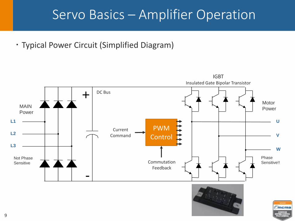
Servo Basics – Amplifier Operation
Typical Power Circuit (Simplified Diagram)
L1
L2
L3
U
V
W
+
-
MAIN
Power
Motor
Power
Not Phase
Sensitive
Phase
Sensitive!!
Current Command
Commutation Feedback
PWM Control
9
DC Bus
IGBTInsulated Gate Bipolar Transistor
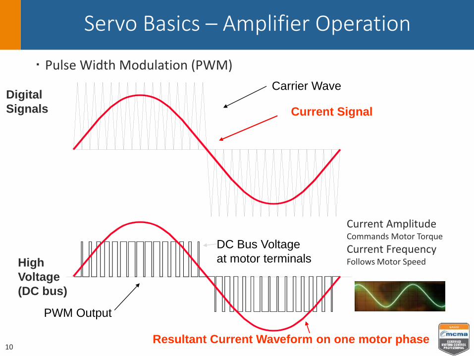
Servo Basics – Amplifier Operation
Pulse Width Modulation (PWM)
Carrier Wave
Current Signal
PWM Output
Resultant Current Waveform on one motor phase
Digital
Signals
High
Voltage
(DC bus)
DC Bus Voltage
at motor terminals
Current Amplitude Commands Motor Torque
Current Frequency Follows Motor Speed
10
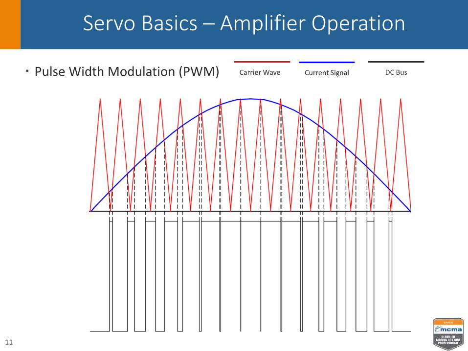
Servo Basics – Amplifier Operation
Pulse Width Modulation (PWM)
11
Carrier Wave Current Signal DC Bus
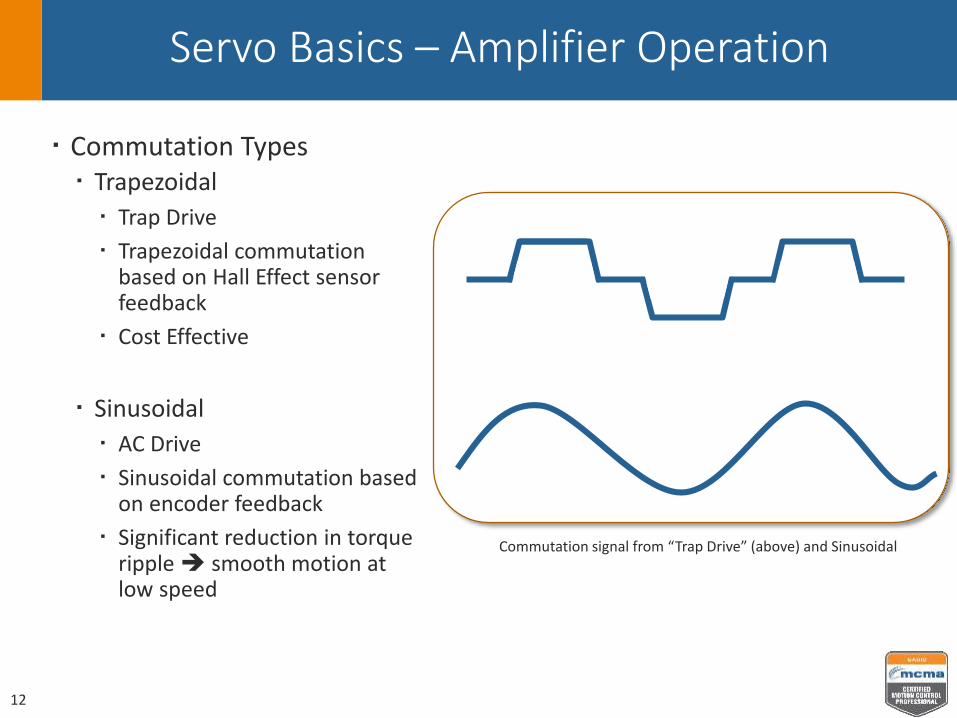
Servo Basics – Amplifier Operation
Commutation Types Trapezoidal
Trap Drive
Trapezoidal commutationbased on Hall Effect sensor feedback
Cost Effective
Sinusoidal
AC Drive
Sinusoidal commutation based on encoder feedback
Significant reduction in torque ripple smooth motion at low speed
Commutation signal from “Trap Drive” (above) and Sinusoidal
12

Servo Basics – Servo ON
PWM is active
Servo “Enable” or “Power”
Control circuit is active
Current amplitude may be very low
13
U
V
W
PWM Control
+-Command
Error
Current Feedback

Digital Servo Amplifier Basics
Servo Basics1. What is a Servo?2. Input Command3. Amplifier Operation
Digital Control Loops1. Function2. Examples3. Types4. Bandwidth5. Tuning Process6. Tuning Filters
Amplifier Power1. Input Types2. Regeneration3. DC Bus Sharing
Installation Infrastructure1. Power Wiring2. Noise Filter3. EMI4. Heat Loads
14

Digital Control Loops - Function
Function and architecture of digital control loop Command is compared to Feedback The difference is Error Gain amplifies Error Output Command is the amplified Error
Q: Why close the loop? A: Minimize and eliminate ERROR
+-
PWMCommand
Feedback
Error
CommandOutput
Gain
15

Digital Control Loops - Examples
Examples of closed loop systems
Cruise Control
Furnace with “smart” thermostat
16
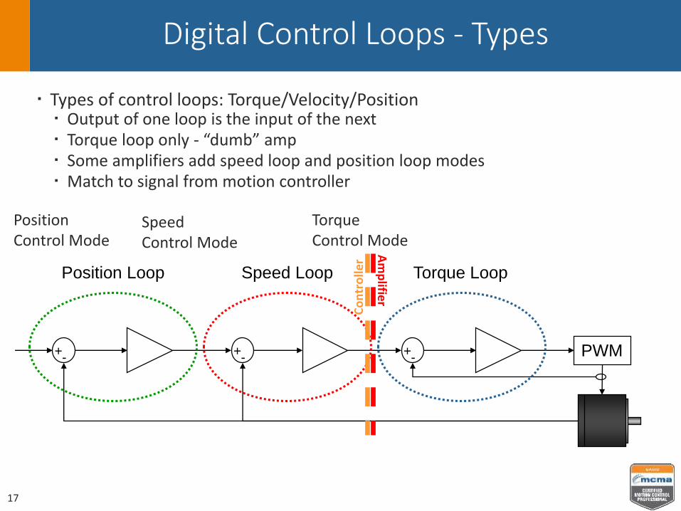
Digital Control Loops - Types
Types of control loops: Torque/Velocity/Position Output of one loop is the input of the next Torque loop only - “dumb” amp Some amplifiers add speed loop and position loop modes Match to signal from motion controller
+-
+-
+- PWM
Torque LoopSpeed LoopPosition Loop
Am
plifie
r
Co
ntr
olle
r
Torque Control Mode
Speed Control Mode
PositionControl Mode
17

Digital Control Loops – Bandwidth
Bandwidth is the useable range of frequencies for a control loop -when the output amplitude reduces to -3dB (70.7%) of the input.
AOUT
f
AIN
ff
Servo Amplifier
PWM
Torque Loop
Frequency (Hz)
Torque Loop Bandwidth (fc)
-3 dB
Bode Plot
Bandwidth
18
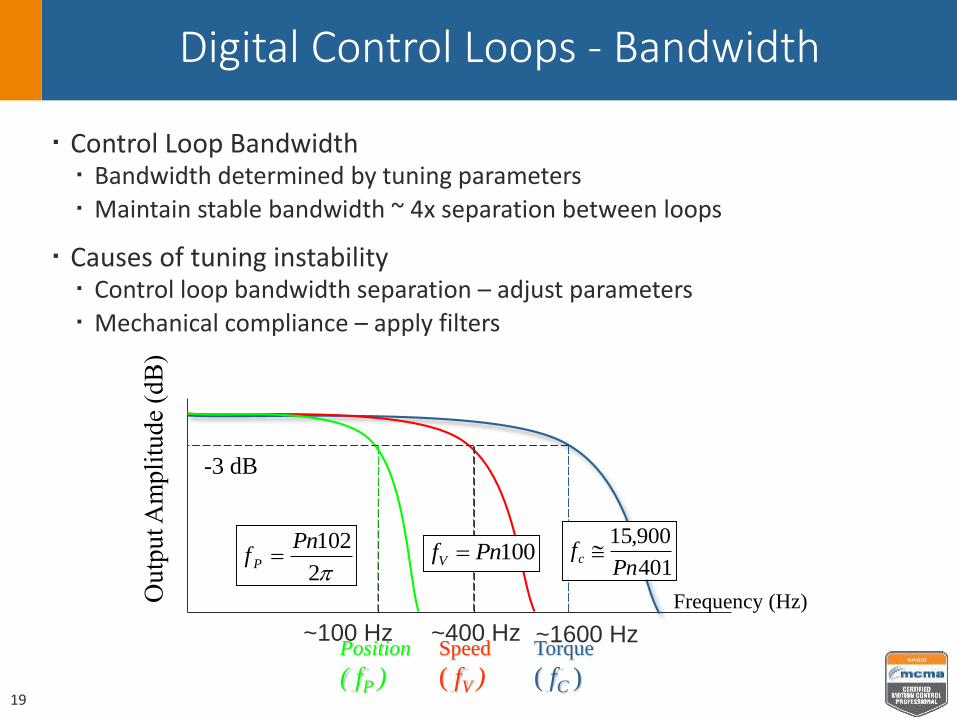
Digital Control Loops - Bandwidth
Control Loop Bandwidth Bandwidth determined by tuning parameters
Maintain stable bandwidth ~ 4x separation between loops
Causes of tuning instability Control loop bandwidth separation – adjust parameters
Mechanical compliance – apply filters
Frequency (Hz)
Speed
( fV )
Position
( fP )
-3 dB
Torque
( fC )
401
900,15
Pnfc 100PnfV
2
102Pnf P
~100 Hz ~400 Hz ~1600 Hz
19
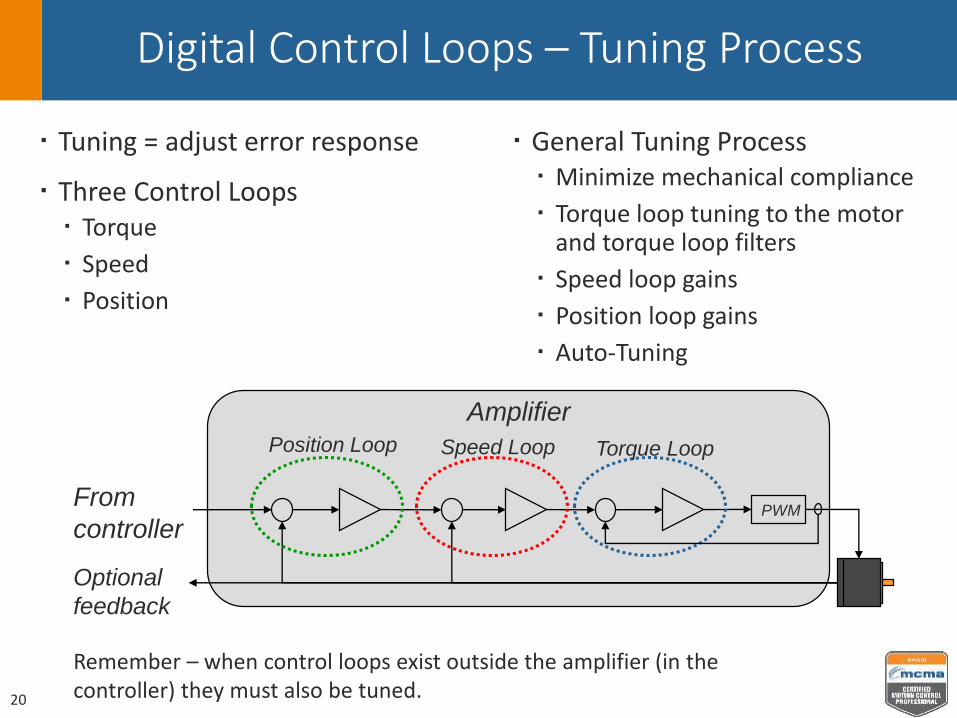
Digital Control Loops – Tuning Process
Tuning = adjust error response
Three Control Loops Torque
Speed
Position
General Tuning Process Minimize mechanical compliance
Torque loop tuning to the motor and torque loop filters
Speed loop gains
Position loop gains
Auto-Tuning
PWM
Torque LoopSpeed LoopPosition Loop
Amplifier
From
controller
Optional
feedback
Remember – when control loops exist outside the amplifier (in the controller) they must also be tuned.20

Digital Control Loops – Tuning Filters
Low Pass Filter
Notch Filter
Advanced filters for lower frequencies
Measurement can reveal problem frequencies caused by mechanical compliance
21
Notch Filter

Digital Servo Amplifier Basics
Servo Basics1. What is a Servo?2. Input Command3. Amplifier Operation
Digital Control Loops1. Function2. Examples3. Types4. Bandwidth5. Tuning Process6. Tuning Filters
Amplifier Power1. Input Types2. Regeneration3. DC Bus Sharing
Installation Infrastructure1. Power Wiring2. Noise Filter3. EMI4. Heat Loads
22

Amplifier Power – Input Types
Amplifier Power Input Types DC – Power Supply AC – 100V, 200V, 400V internal power supply
Considerations Available Power Servo Capacity – higher capacity available in higher voltages Current rating drives the cost of an amplifier
23

Amplifier Power - Regeneration
“Regeneration” means that the motor is generating energy rather than using energy
This happens during deceleration because the load forces the motor to move in the direction opposite to that in which torque is being applied
Factors that Increase Regen
• High Speed
• High Inertia
• High Deceleration Rate
• Vertical Applications
• Low Friction
Torque
Speed
Regen
Speed is positive
Torque is negative
24
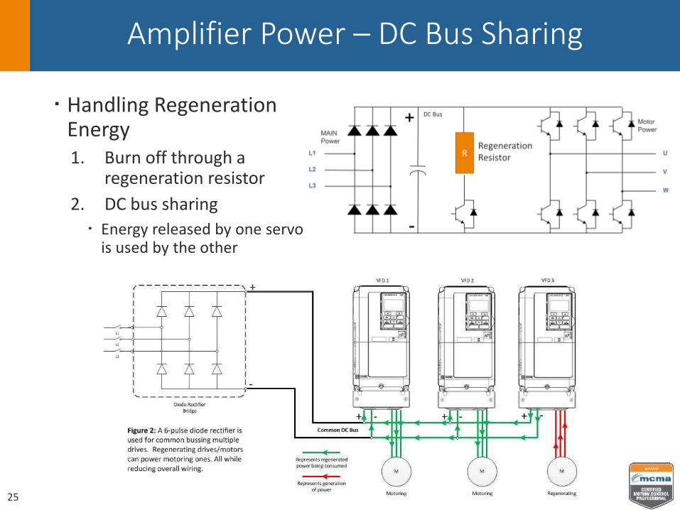
Amplifier Power – DC Bus Sharing
Handling Regeneration Energy1. Burn off through a
regeneration resistor
2. DC bus sharing
Energy released by one servo is used by the other
25
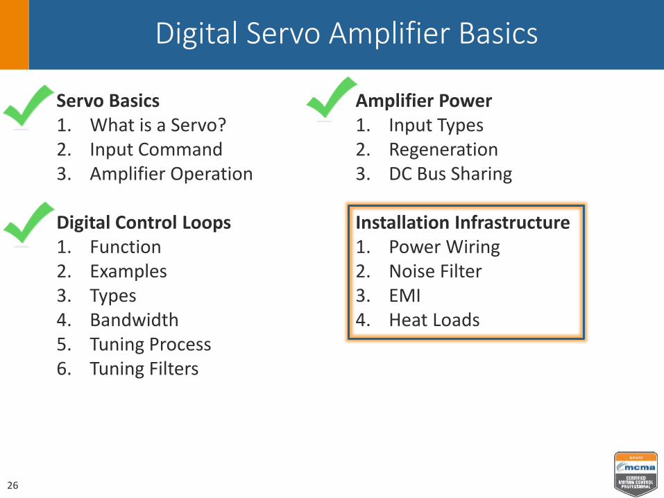
Digital Servo Amplifier Basics
Servo Basics1. What is a Servo?2. Input Command3. Amplifier Operation
Digital Control Loops1. Function2. Examples3. Types4. Bandwidth5. Tuning Process6. Tuning Filters
Amplifier Power1. Input Types2. Regeneration3. DC Bus Sharing
Installation Infrastructure1. Power Wiring2. Noise Filter3. EMI4. Heat Loads
26

Installation Infrastructure – Power Wiring
Input Power Noise Filter
Contactor
Main Power
Control Power
Peripheral Devices
Regeneration Resistor
27

Installation Infrastructure – Noise Filter
Noise Filter Protect other devices on the AC power
line from the electrical noise created by the amplifier PWM
28

Installation Infrastructure – EMI
Electromagnetic Interference (EMI) Radiated Conducted
Good wiring practices Single point “star” grounding Isolate earth ground from DC power
supply output Physical separation of power cables
and signal cables Shielded cable Twisted pairs
29

Installation Infrastructure – Heat Loads
Heat Loads / Cooling Mounting separation specification
Flat, vertical mounting surface for heat conduction and convection
Amplifier generates heat from power loss
30

Thank You!
Fundamentals of digital servo amplifiers still apply
Advancements in Technology Better performance
More Options
New Applications
31

Speaker Contact Details
Matt Pelletier
Product Training Engineer
Yaskawa America Inc.
2121 Norman Drive South
Waukegan IL, 60085
847-887-7000
32