digital radio transmission - problems - cse...
TRANSCRIPT

Digital Radio Transmission -Problems

Gergely Zaruba - CSE6344 Fall 2001
Radio Transmission! Problem: there is no wiring or cables
with radio transmissions! Radio signals can become week to an
unacceptable level
! Is the radio interface limited by noise or by interference?
Gergely Zaruba - CSE6344 Fall 2001
Transmission Problems! Path Loss! Fading
! Log-normal fading! Rayleigh or multipath fading
! Time Dispersion! High BER! Radio switch-over times! Hidden terminal problem! Signal lock-on
Gergely Zaruba - CSE6344 Fall 2001
Path Loss (Ls)! The received signal becomes weaker with the
increasing distance between transmitting unit (Tx) and receiving (Rx) unit.
! In a free space propagation environment:! Ls ~ d2f2
Assuming, that the two units are relatively close
(to be used, e.g., in an cellular environment)
Gergely Zaruba - CSE6344 Fall 2001
Path Loss (Ls)
! Non-ideal ground plane must be considered in an non-open environment. ! Ls ~ d4f2
In practice more complex models (Egli or
Okomura models) are used. When
modeling radio layer for ad hoc networks
more sophisticated models may be used.
Gergely Zaruba - CSE6344 Fall 2001
Log-normal Fading! Caused by the shadowing effect of
obstacles. When nodes move around, signal strength can vary depending on the obstacles between the Tx and Rx nodes.
! The minimums in a signal strength are called fading dips.

Gergely Zaruba - CSE6344 Fall 2001
Log-normal Fading! Log-normal: the logarithm of the signal
strength takes the form of a normal distribution (bell curve with negative exponential convergence) around a mean value.
! The distance between fading dips is typically some 10 to 20 meters in a GSM (900MHz) environment.

Gergely Zaruba - CSE6344 Fall 2001
Rayleigh Fading! Caused by the signal taking more than one
path from Tx to Rx due to signal “bouncing” of from obstacles.
! Especially hard problem in urban environments.
! There is usually no line-of-sight, the signal reaches the destination via several reflections against obstacles (buildings, etc.).
Gergely Zaruba - CSE6344 Fall 2001
Rayleigh Fading! The received signal is a sum of many
identical but time dispersed signals.! Since signals have to be added like
vectors (they have phase and amplitude), the sum of the received signals can easily reach an unacceptable low value.

Gergely Zaruba - CSE6344 Fall 2001
Rayleigh Fading! The distance between two fading dips
(drf) is about half a wavelength.
0.029m5.2 GHz
0.0625m2.4 GHz
0.088m1700 MHz
0.187m800 MHz
drfFrequency
Gergely Zaruba - CSE6344 Fall 2001
Rayleigh Fading an Example! Since the distance between two fading
dips (drf) is about half a wavelength: If you travel with a speed of 50km/h
(~30mph) using your 800MHz handset, the mean time between Rayleigh fading dips is approximately 13.3msec !!
Gergely Zaruba - CSE6344 Fall 2001
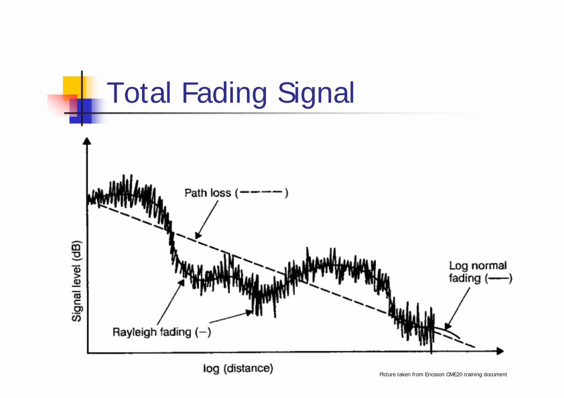
Total Fading Signal
Picture taken from Ericsson CME20 training document

Gergely Zaruba - CSE6344 Fall 2001
Time Dispersion! The problem again lies in reflection of
signals from obstacles.! Time dispersion causes inter symbol
interference, meaning, that consecutive symbols interfere with each other.

Gergely Zaruba - CSE6344 Fall 2001
Time Dispersion1
1

Gergely Zaruba - CSE6344 Fall 2001
Time Dispersion0
0
1
1

Gergely Zaruba - CSE6344 Fall 2001
Time Dispersion0
0
0
0
1

Gergely Zaruba - CSE6344 Fall 2001
High Bit Error Rate (BER)! The BER difference between optical
and wireless transmission is in the order of 107 – 1010 ; values down to 10-3 are not uncommon
! Furthermore, errors are likely to appear in bursts (lightning, interference of other devices, etc.)
Gergely Zaruba - CSE6344 Fall 2001
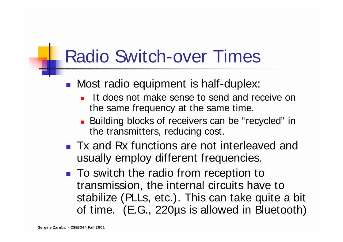
Radio Switch-over Times! Most radio equipment is half-duplex:
! It does not make sense to send and receive on the same frequency at the same time.
! Building blocks of receivers can be “recycled” in the transmitters, reducing cost.
! Tx and Rx functions are not interleaved and usually employ different frequencies.
! To switch the radio from reception to transmission, the internal circuits have to stabilize (PLLs, etc.). This can take quite a bit of time. (E.G., 220µs is allowed in Bluetooth)

Gergely Zaruba - CSE6344 Fall 2001
Signal Lock-on! If a radio starts receiving a signal, it locks
itself on the signal (e.g., using PLLs). ! If there is another signal interfering after the
lock-on the receiver circuits may still receive the first signal (signal carriers are unlikely to be on the “exact” same frequency).
! More of a phenomenon than a problem, although it can cause some strange effects.
Gergely Zaruba - CSE6344 Fall 2001
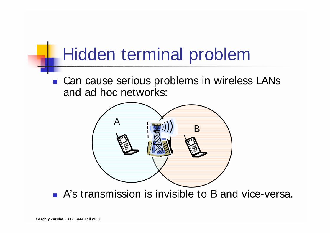
Hidden terminal problem! Can cause serious problems in wireless LANs
and ad hoc networks:
! A’s transmission is invisible to B and vice-versa.
AB

Digital Radio Transmission -Solutions

Gergely Zaruba - CSE6344 Fall 2001
Power Control! To reduce interference Tx units can
progressively reduce transmission power.
! Rx unit determines the reception power and informs the transmitting party on the reception level.
! Primary function is (was) not to save power from batteries nor is it to reduce radiation pollution harmful to the body.

Gergely Zaruba - CSE6344 Fall 2001
Channel Coding! Wireless medium is know for high BER! We have to allow certain amount of
errors and still be able to restore information or detect errors.
! Some redundancy needs to be built in in the data stream.
Gergely Zaruba - CSE6344 Fall 2001
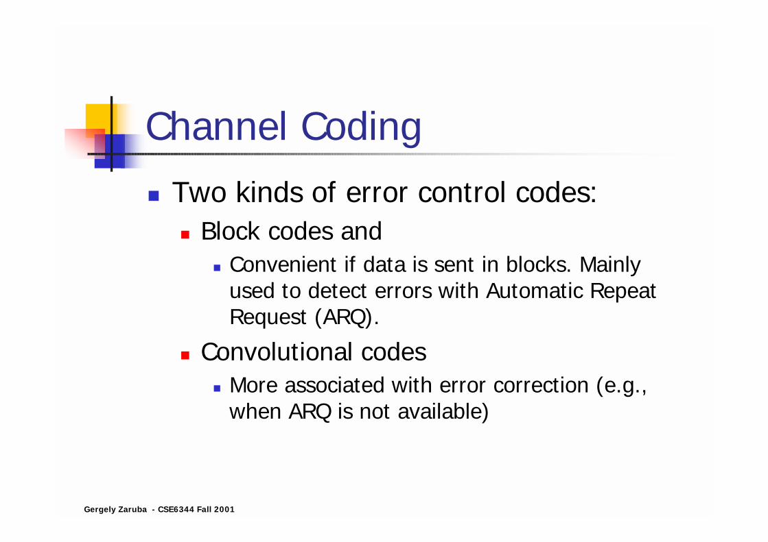
Channel Coding! Two kinds of error control codes:
! Block codes and! Convenient if data is sent in blocks. Mainly
used to detect errors with Automatic Repeat Request (ARQ).
! Convolutional codes! More associated with error correction (e.g.,
when ARQ is not available)
Gergely Zaruba - CSE6344 Fall 2001
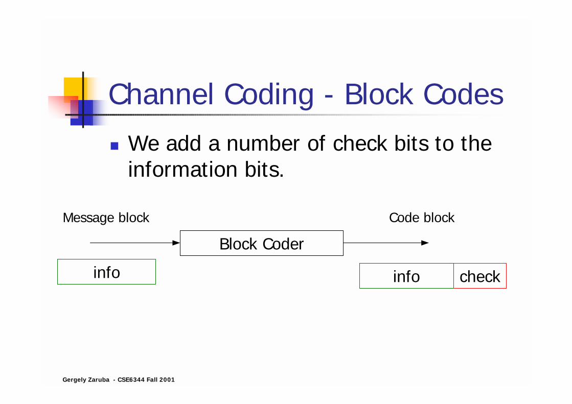
Channel Coding - Block Codes! We add a number of check bits to the
information bits.
Block Coder
info info check
Message block Code block

Gergely Zaruba - CSE6344 Fall 2001
Channel Coding – Conv. Codes! The block of encoded digits depends
not only on the digits in the current message block but also on that of the preceding blocks.
Convolutional Coder
info info coded info
Message block Coded into stream

Gergely Zaruba - CSE6344 Fall 2001
Interleaving! Bit errors come in bursts.! Channel coding is to correct single errors.! Results in delay
! Can be more than one level
1 2 3 4 1 2 3 4 1 2 3 4 1 2 3 4
1 1 1 1 2 2 2 2 3 3 3 3 4 4 4 4
Message blocks
Interleaving
Interleaved message blocks
Gergely Zaruba - CSE6344 Fall 2001
Frequency Hopping! Rayleigh fading is frequency dependent
" Fading dips occur at different places for different frequencies
! Let us change carrier frequency between a number of frequencies" We only lose a fraction of information
# Spreads out the spectrum of transmission (fast frequency hopping is a Digital Spread Spectrum (DSS) technique)

Gergely Zaruba - CSE6344 Fall 2001
Advanced Modulation Techniques
! Amplitude modulation (AM) is far away past.
! So is frequency modulation (FM).! Digital modulations are used for
independence from the received signal amplitude (e.g., Gaussian Minimum Shift Keying (GMSK – used in GSM) that is a phase modulator with a Gaussian filter to smooth out the signal)

Gergely Zaruba - CSE6344 Fall 2001
Equalizers! An optimum receiver is adopted to the
type of channel used for transmission, meaning that the receiver has to be always aware of the current state of the channel and adjust itself to the channel.
! Equalizer creates a model of the channel by listening to a well-known training sequence.

Gergely Zaruba - CSE6344 Fall 2001
Radio Transmission in GSM
Picture taken from Ericsson CME20 training document

Gergely Zaruba - CSE6344 Fall 2001
Example of Coding: GSM
Picture taken from Ericsson CME20 training document
The speech is divided into 20ms segments. These 20ms speech segments are digitized and speech coded.The speech coder delivers 260 bits for each segment, which are divided into: