digital circuit and system-ii - northern india … can be represented using vhdl. consider example...
TRANSCRIPT

Digital Circuit And System-II
By: Gaurav Verma
Asst. Prof.
ECE Dept.


INTRODUCTION
The VHSIC Hardware Description Language (VHDL) is an
industry standard language used to describe hardware from the
abstract to concrete level.
The language not only defines the syntax but also
definesvery clear simulation semantics for each language
construct.
It is strong typed language and is often verbose to write.
Provides extensive range of modeling capabilities,it is possible
to quickly assimilate a core subset of the language that is both
easy and simple to understand without learning the more
complex features.

Why Use VHDL?
Quick Time-to-Market
• Allows designers to quickly develop designs requiring tens of thousands of logic gates
• Provides powerful high-level constructs for describing
complex logic
• Supports modular design methodology and multiple levels of hierarchy
One language for design and simulation
Allows creation of device-independent designs that are portable to multiple vendors. Good for ASIC Migration
Allows user to pick any synthesis tool, vendor, or device

BASIC FEATURES OF VHDL
CONCURRENCY.
SUPPORTS SEQUENTIAL STATEMENTS.
SUPPORTS FOR TEST & SIMULATION.
STRONGLY TYPED LANGUAGE.
SUPPORTS HIERARCHIES.
SUPPORTS FOR VENDOR DEFINED LIBRARIES.
SUPPORTS MULTIVALUED LOGIC.

CONCURRENCY
VHDL is a concurrent language.
HDL differs with Software languages with respect to
Concurrency only.
VHDL executes statements at the same time in
parallel,as in Hardware.

SUPPORTS SEQUENTIAL STATEMENTS
VHDL supports sequential statements also, it executes one
statement at a time in sequence only.
As the case with any conventional languages.
example:
if a=„1‟ then
y<=„0‟;
else
y<=„1‟;
end if ;
SUPPORTS FOR TEST & SIMULATION.
To ensure that design is correct as per the specifications, the
designer has to write another program known as “TEST
BENCH”.
It generates a set of test vectors and sends them to the design
under test(DUT).
Also gives the responses made by the DUT against
aspecifications for correct results to ensure the functionality.

STRONGLY TYPED LANGUAGE
VHDL allows LHS & RHS operators of same type.
Different types in LHS & RHS is illegal in VHDL.
Allows different type assignment by conversion.
example:
A : in std_logic_vector(3 downto 0).
B : out std_logic_vector(3 downto 0).
C : in bit_vector(3 downto 0).
B <= A; --perfect.
B <= C; --type miss match,syntax error.

SUPPORTS HIRERCHIES
Hierarchy can be represented using VHDL.
Consider example of a Full-adder which is the top-level module,
being composed of three lower level modules i.e. Half-Adder and
OR gate.
example :

LEVELS OF ABSTRACTION
Data Flow level
• In this style of modeling the flow of data through the entity is
expressed using concurrent signal assignment statements. Structural level
• In this style of modeling the entity is described as a set of
interconnected statements. Behavioral level.
• This style of modeling specifies the behavior of an entity as
a set of statements that are executed sequentially in the
specified order.
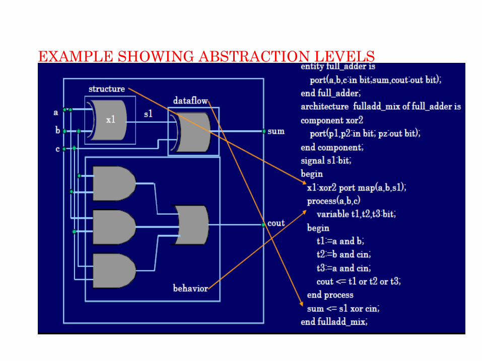
EXAMPLE SHOWING ABSTRACTION LEVELS

VHDL IDENTIFIERS
Identifiers are used to name items in a VHDL model.
A basic identifier may contain only capital „A‟ - ‟Z‟ , „a‟ -
‟z‟, „0‟ - ‟9‟, underscore character „_‟
Must start with a alphabet.
May not end with a underscore character.
Must not include two successive underscore characters.
Reserved word cannot be used as identifiers.
VHDL is not case sensitive.

OBJECTS
There are three basic object types in VHDL
• Signal : represents interconnections that connect components
and ports.
• Variable : used for local storage within a process.
• Constant : a fixed value.
The object type could be a scalar or an array.

DATA TYPES IN VHDL
Type
• Is a name which is associated with a set of values and a set
of operations. Major types:
• Scalar Types
• Composite Types
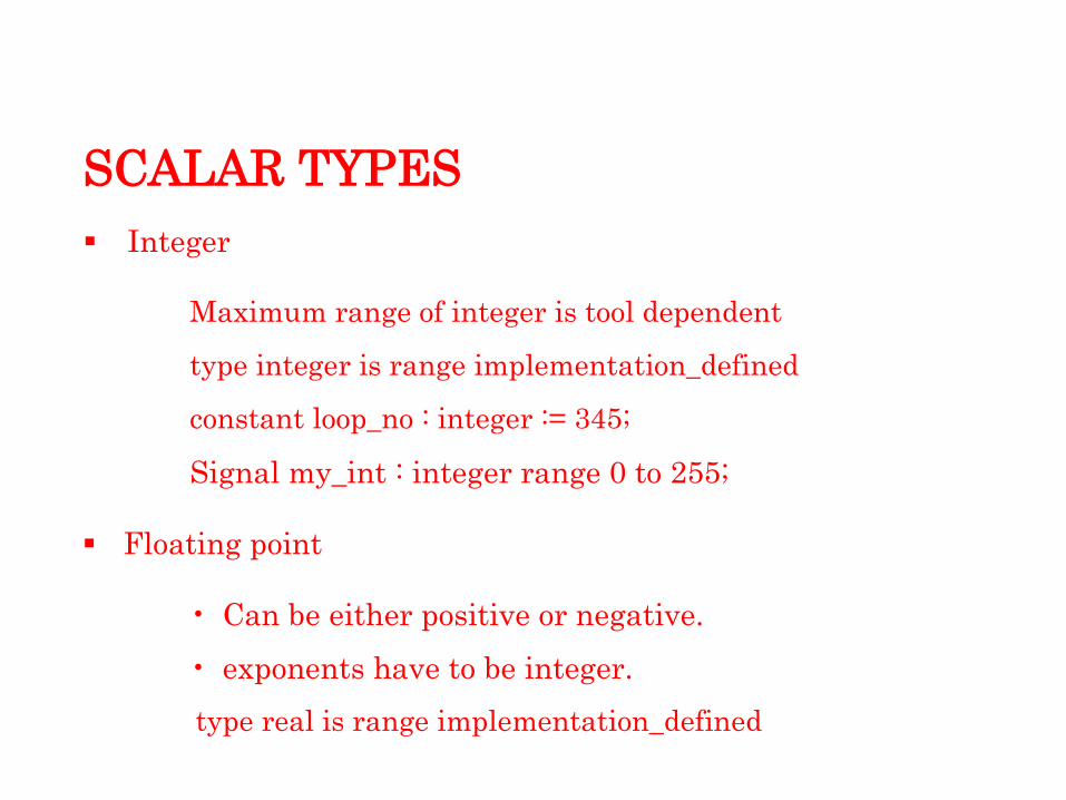
SCALAR TYPES
Integer
Maximum range of integer is tool dependent
type integer is range implementation_defined
constant loop_no : integer := 345;
Signal my_int : integer range 0 to 255;
Floating point
• Can be either positive or negative.
• exponents have to be integer.
type real is range implementation_defined

SCALAR TYPES (Cont..)
Physical
Predefined type “Time” used to specify delays.
Example :
type TIME is range -2147483647 to 2147483647
Enumeration
Values are defined in ascending order.
Example:
type alu is ( pass, add, subtract, multiply,divide )

COMPOSITE TYPES
There are two composite types
ARRAY :
• Contain many elements of the same type.
• Array can be either single or multidimensional.
• Single dimensional array are synthesizable.
• The synthesis of multidimensional array depends upon the synthesizer being used.
RECORD :Contain elements of different types.
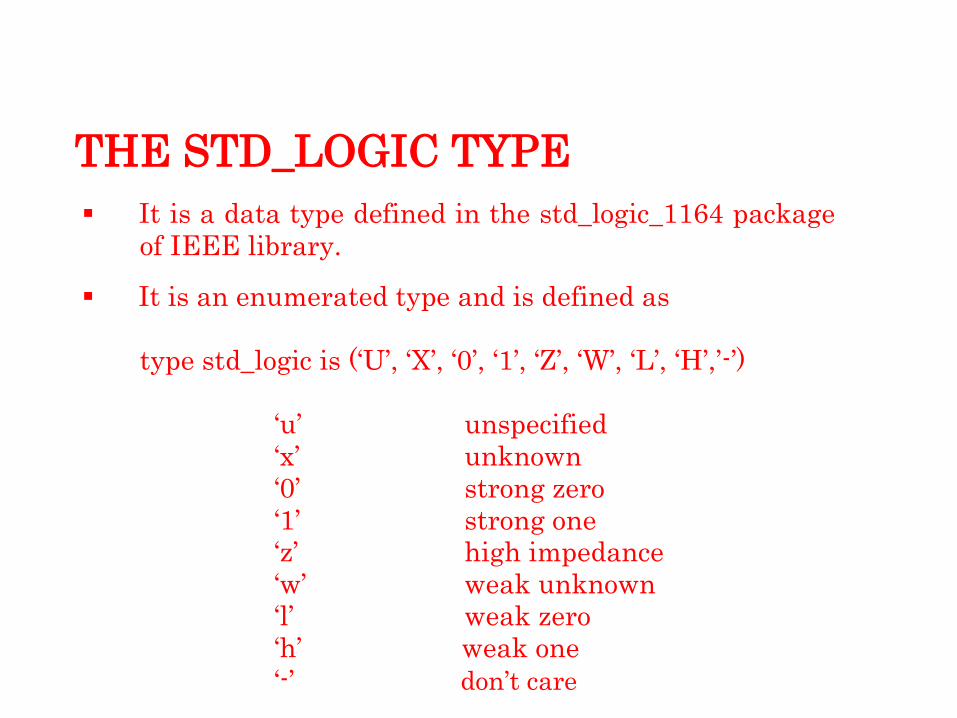
THE STD_LOGIC TYPE
It is a data type defined in the std_logic_1164 package
of IEEE library.
It is an enumerated type and is defined as
type std_logic is („U‟, „X‟, „0‟, „1‟, „Z‟, „W‟, „L‟, „H‟,‟-‟)
„u‟ unspecified
„x‟ unknown
„0‟ strong zero
„1‟ strong one
„z‟ high impedance
„w‟ weak unknown
„l‟ weak zero
„h‟ weak one
„-‟ don‟t care
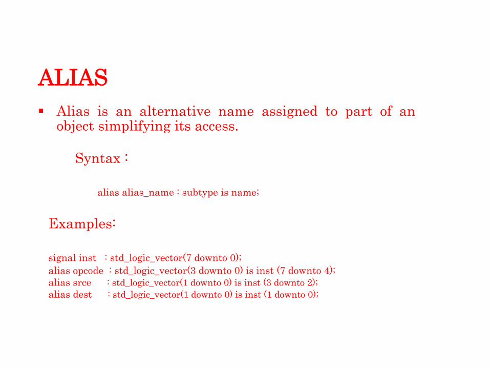
ALIAS
Alias is an alternative name assigned to part of an object simplifying its access.
Syntax :
alias alias_name : subtype is name;
Examples:
signal inst : std_logic_vector(7 downto 0);
alias opcode : std_logic_vector(3 downto 0) is inst (7 downto 4);
alias srce : std_logic_vector(1 downto 0) is inst (3 downto 2);
alias dest : std_logic_vector(1 downto 0) is inst (1 downto 0);

SIGNAL ARRAY
A set of signals may also be declared as a signal array which is a concatenated set of signals.
This is done by defining the signal of type bit_vector or std_logic_vector.
bit_vector and std_logic_vector are types defined in the ieee.std_logic_1164 package.
Signal array is declared as :
<type>(<range>) Example:
signal data1:bit_vector(1 downto 0) signal data2: std_logic_vector(7 down to 0);
signal address : std_logic_vector(0 to 15);

SUBTYPE
It is a type with a constraint
Useful for range checking and for imposing additional
constraints on types.
syntax:
subtype subtype_nameis base_type range range_constraint;
example:
subtype DIGITS is integer range 0 to 9;

MULTI-DIMENSIONAL ARRAYS
Syntax
type array_name is array (index _ range , index_range) of element_ type;
example:
type memory is array (3 downto 0, 7 downto 0);
For synthesizers which do not accept multidimensional
arrays,one can declare two uni- dimensional arrays.
example:
type byte is array (7 downto 0) of std_logic;
type mem is array (3 downto 0) of byte;

OPERATORS
precedence Operator class
Operators
Low Logical and or nand nor Xor xnor
Relational = /= < <= > >=
Shift sll srl sla sra rol ror
Add + - &
Sign + -
Multiply * / mod rem
Miscella- ** abs not
neous
High
Data Flow Modeling

DATAFLOW LEVEL
A Dataflow model specifies the functionality of the entity
without explicitly specifying its structure.
This functionality shows the flow of information through the
entity, which is expressed primarily using concurrent signal
assignment statements and block statements.
The primary mechanism for modeling the dataflow behavior of
an entity is using the concurrent signal assignment statement.

ENTITY
Entity describes the design interface.
The interconnections of the design unit with the external world are enumerated.
The properties of these interconnections are
defined. entity declaration:
entity <entity_name> is
port ( <port_name> : <mode>
<type>; …. );
end <entity_name>;

There are four modes for the ports in
VHDL in, out, inout, buffer
These modes describe the different kinds of interconnections that the port can have with the external circuitry.
Sample program:
entity andgate is
port ( c : out bit;
a : in bit;
b : in bit );
end andgate;

ARCHITECTURE
Architecture defines the function-
ality of the entity.
entity architecture
It forms the body of the VHDL code.
An architecture belongs to a speci- fic entity.
Various constructs are used in thedescription of the architecture.
architecture declaration:
architecture <architecture_name>
of <entity_name> is
<declarations>
begin <vhdl statements>
end <architecture_name> ;
ports

EXAMPLE OF A VHDL ARCHITECTURE
entity andgate is
port (c : out bit;
a : in bit;
b : in bit
);
end andgate;
architecture arc_andgate of andgate
is begin
c <= a and b;
end arc_andgate;
a
and gate c
b
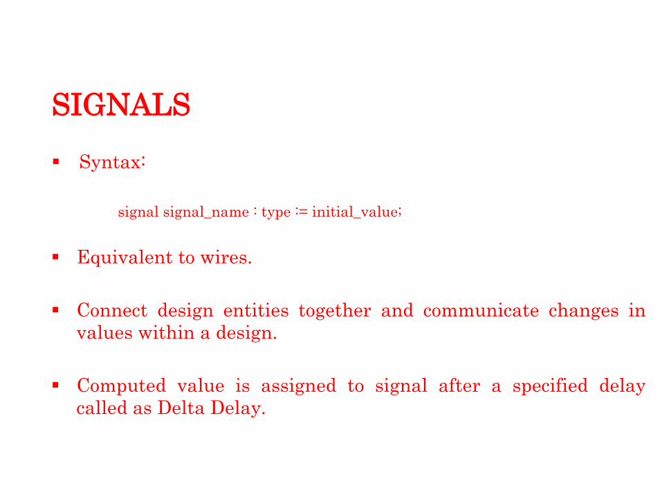
SIGNALS
Syntax:
signal signal_name : type := initial_value;
Equivalent to wires.
Connect design entities together and communicate changes in
values within a design.
Computed value is assigned to signal after a specified delay
called as Delta Delay.
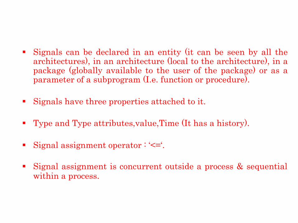
Signals can be declared in an entity (it can be seen by all the architectures), in an architecture (local to the architecture), in a package (globally available to the user of the package) or as a parameter of a subprogram (I.e. function or procedure).
Signals have three properties attached to it.
Type and Type attributes,value,Time (It has a history).
Signal assignment operator : „<=„.
Signal assignment is concurrent outside a process & sequential within a process.
CONCATENATION
This is the process of combining two signals into a single set
which can be individually addressed.
The concatenation operator is „&‟.
A concatenated signal‟s value is written in double quotes
whereas the value of a single bit signal is written in single
quotes.

WITH-SELECT
The with-select statement is used for selective signal assignment.
It is a concurrent statement.
Syntax
with expression select:
target <= expression 1 when choice1
expression 2 when choice2 . . . expression N when others;
Example:
entity mux2 is port ( i0, i1 : in bit_vector(1 downto 0); y
: out bit_vector(1 downto 0);
sel : in bit );
end mux2;
architecture behaviour of mux2
is begin
with sel select
y <= i0 when
'0', i1 when '1';
end behaviour;

WHEN-ELSE
syntax :
Signal_name<= expression1 when condition1 else
expression2 when condition2 else
expression3;
Example:
entity tri_state is
port (a, enable : in std-logic;
b : out std_logic);
end tri_state;
architecture beh of tri_state is
begin
b <= a when enable =„1‟ else
„Z‟;
end beh;

WHEN-ELSE VS. WITH-SELECT
In the „with‟ statement,choice is limited to the choices provided by the with „express-ion‟.
In the „when‟ statement each choice itself can be a separate expression.
when statement is prioritized ( since each choice can be a
different expression,more than one condition can be true at the same time, thus necessitating a priority based assignment)
with statement does not have any priority (since choices are mutually exclusive) .

DELAYS IN VHDL
VHDL allows signal assignments to include delay
specifications, in the form of an „after‟ clause.
The „after‟ clause allows you to model the behavior of gate and
delays.
Delay‟s are useful in simulation models to estimate delays in
synthesizable design.
Two fundamental delays are
• Inertial delay.
• Transport Delay.
INERTIAL DELAY
Inertial Delay models the delays often found in switching circuits
(component delays).
These are default delays.
Spikes are not propagated if after clause is used.
An input value must be stable for an specified pulse rejection limit
duration before the value is allowed to propagate to the output.

INERTIAL DELAY (Cont..)
Inertial delay is used to model component delay.
Spike of 2ns in cmos component with delay of 10ns is normally not seen at the output.
Problem arises if we want to model a component with delay of 10ns, but all spikes at input > 5 ns are visible output.
Above problem can be solved by introducing reject & modeling as follows:
outp <= reject 5 ns inertial Inp after 10 ns;
TRANSPORT DELAY
Transport delay models the behavior of a wire, in which all
pulses (events) are propagated.
Pulses are propagated irrespective of width.
Good for interconnect delays.
Models delays in hardware that does not exhibit any inertial
delay.
Represents pure propagation delay
Routing delays can be modeled using transport
delay Z<= transport a after 10 ns;

SIMULATION DELTAS
It is used to achieve Concurrency & order independence in zero
delay models using event scheduling.
A delta delay is an infinitesimal interval that never
accumulated to an absolute unit.
To better understand the delta time concept, you should think
of simulation time to be two-dimensional.
The following graph depicts the simulation activity of a
hypothetical VHDL model.

SIMULATION DELTAS (Cont..)

DRIVERS
Are created by signal assignment statements
Concurrent signal assignment produces one driver for each
signal assignment
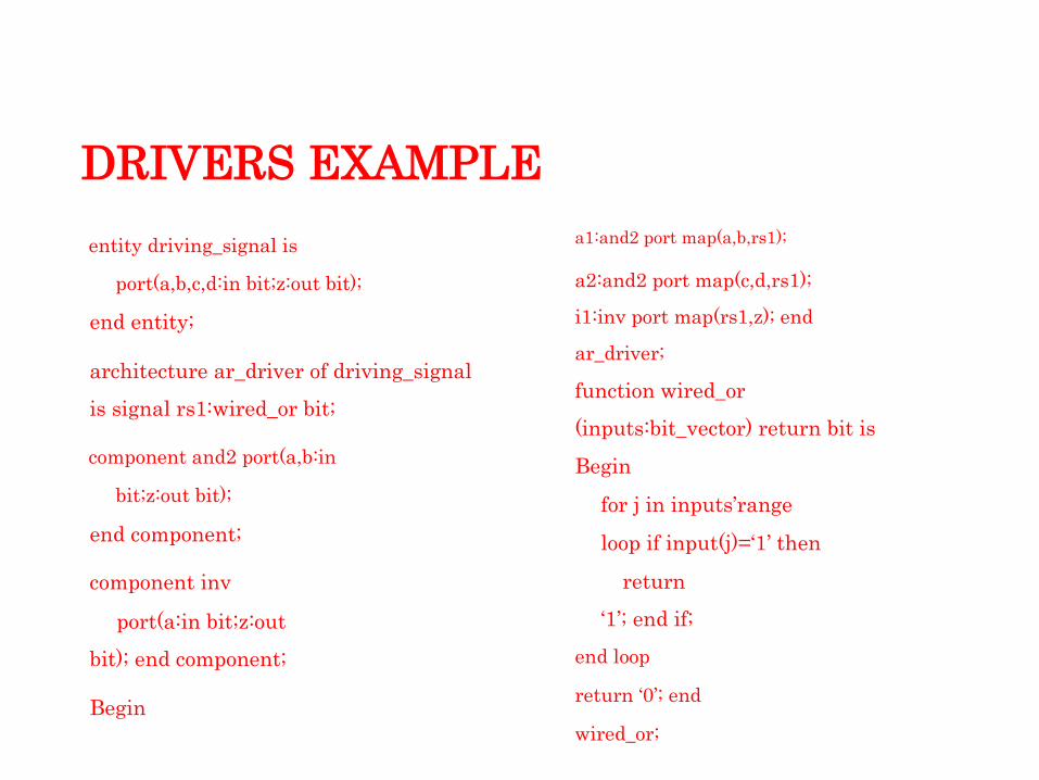
DRIVERS EXAMPLE
entity driving_signal is
port(a,b,c,d:in bit;z:out bit);
end entity;
architecture ar_driver of driving_signal
is signal rs1:wired_or bit;
component and2 port(a,b:in
bit;z:out bit);
end component;
component inv
port(a:in bit;z:out
bit); end component;
Begin
a1:and2 port map(a,b,rs1);
a2:and2 port map(c,d,rs1);
i1:inv port map(rs1,z); end
ar_driver;
function wired_or
(inputs:bit_vector) return bit is
Begin
for j in inputs‟range
loop if input(j)=„1‟ then
return
„1‟; end if; end loop
return „0‟; end
wired_or;
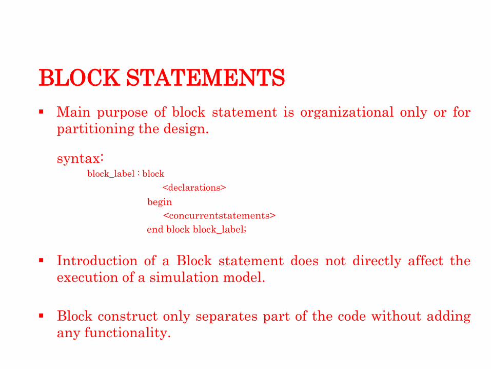
BLOCK STATEMENTS
Main purpose of block statement is organizational only or for
partitioning the design.
syntax:
block_label : block
<declarations>
begin
<concurrentstatements>
end block block_label;
Introduction of a Block statement does not directly affect the
execution of a simulation model.
Block construct only separates part of the code without adding
any functionality.

Behavioral Modeling

BEHAVIOR LEVEL
The behavior of the entity is expressed using sequentially executed, procedural code, which is very similar in syntax and semantics to that of a high level programming languages such as C or Pascal.
Process statement is the primary mechanism used to model the behavior of an entity.
Process statement has a declarative part (before the keyword begin) and a statement part (between the keywords begin and end process).
The statements appearing within the statement part are sequential statements and are executed sequentially.
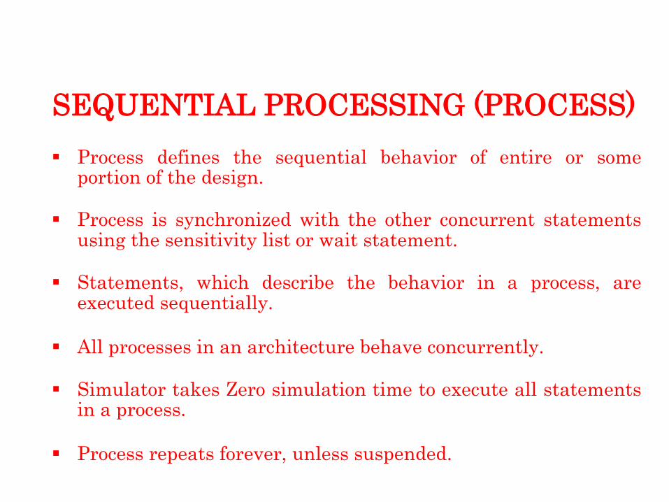
SEQUENTIAL PROCESSING (PROCESS)
Process defines the sequential behavior of entire or some portion of the design.
Process is synchronized with the other concurrent statements using the sensitivity list or wait statement.
Statements, which describe the behavior in a process, are executed sequentially.
All processes in an architecture behave concurrently.
Simulator takes Zero simulation time to execute all statements in a process.
Process repeats forever, unless suspended.

PROCESS (Cont..)
Process can be in waiting or
executing.
syntax:
process (sensitivity list)
<declarations>
begin
<sequential
statements>; end process;
Once the process has started it
takes time delta „t‟ for it to be
moved back to waiting state.
This means that no simulation
time is taken to execute the
process.
process(clk,reset)
begin if reset=„1‟ then
Z<=„0‟; elsif clk‟event and clk = „1‟ then
Z<=(i1 and i2) and i3;
end if;
end process;
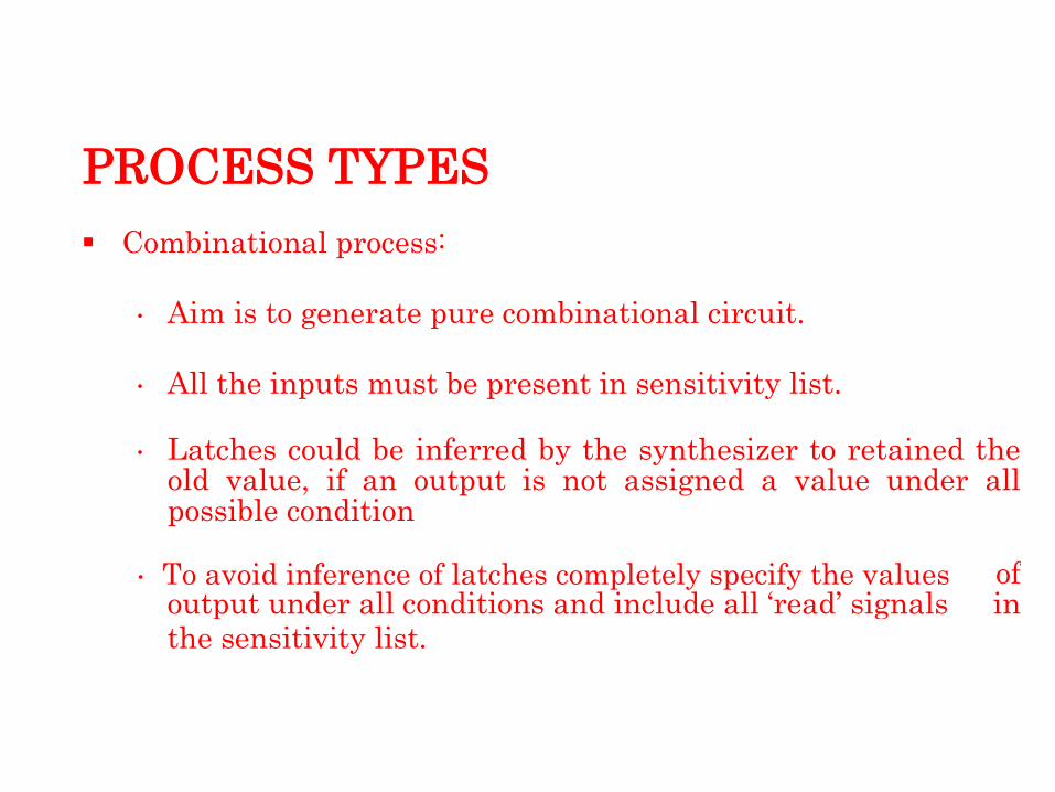
PROCESS TYPES
Combinational process:
• Aim is to generate pure combinational circuit.
• All the inputs must be present in sensitivity list.
• Latches could be inferred by the synthesizer to retained the old value, if an output is not assigned a value under all possible condition
• To avoid inference of latches completely specify the values of
output under all conditions and include all „read‟ signals in
the sensitivity list.

PROCESS TYPES (Cont..)
Clocked processes:
• Clocked processes are synchronous and several such processes can be joined with the same clock.
• Generates sequential and combinational logic.
• All signals assigned within clock detection are registered(i.e. resulting flip-flop)
• Any assignment within clock detection will generate a Flip-flop and all other combinational circuitry will be created at the „D‟ input of the Flip-flop.

SIGNALS WITHIN PROCESS
Process places only one driver on a signal.
Value that the signal is up-dated with is the last value assigned to it within the process execution.
Signals assigned to within a process are not updated with their new values until the process suspends.

SEQUENTIAL CONSTRUCTS
The final output depends on the order of the statements, unlike concurrent statements where the order is inconsequential .
Sequential statements are allowed only inside process.
The process statement is the primary concurrent VHDL statement used to describe sequential behavior.
Sequential statements can be used to generate both combina-tional logic and sequential logic.
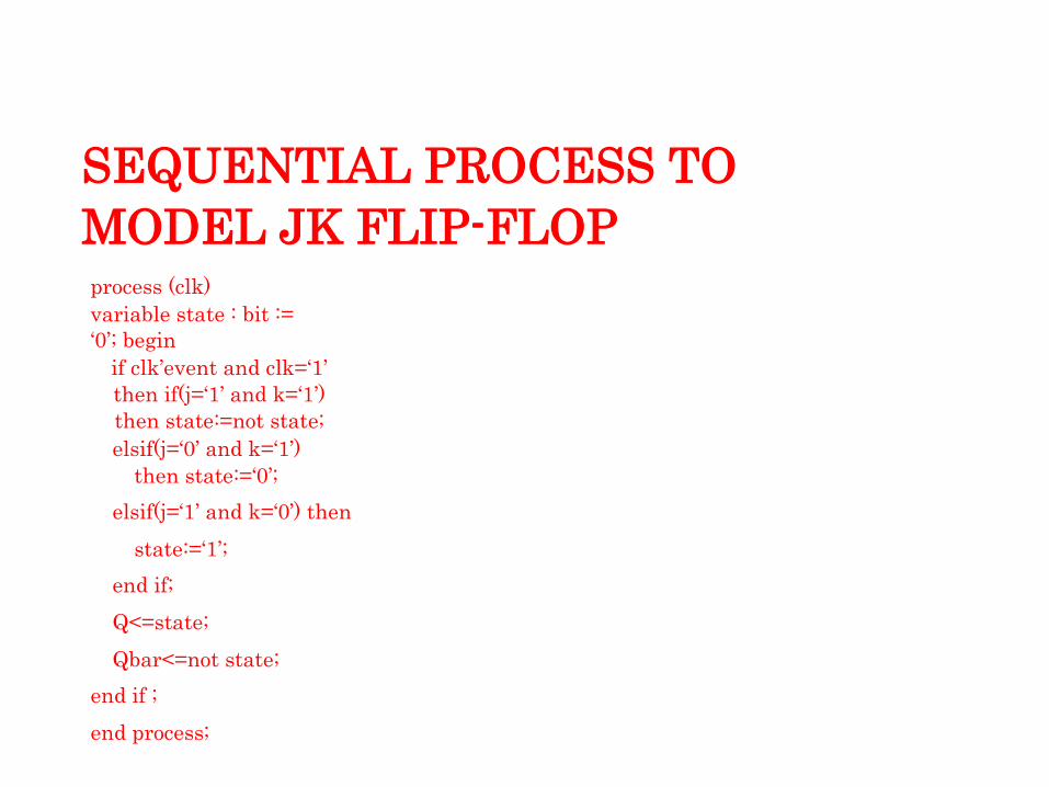
SEQUENTIAL PROCESS TO
MODEL JK FLIP-FLOP
process (clk)
variable state : bit :=
„0‟; begin
if clk‟event and clk=„1‟
then if(j=„1‟ and k=„1‟)
then state:=not state;
elsif(j=„0‟ and k=„1‟)
then state:=„0‟;
elsif(j=„1‟ and k=„0‟) then
state:=„1‟;
end if;
Q<=state;
Qbar<=not state;
end if ;
end process;
VARIABLES
syntax :
variable variable_name: type := initial_value;
Can be declared and used inside a process statement or in subprogram.
Variable assignment occurs immediately.
Variables retain their values throughout the entire simulation Sequential (inside process)
Variable have only type and value attached to it.They don‟t have past history unlike signal.
Require less memory & results in fast simulation

CONSTANTS
syntax :
constant constant_name : type := value;
Constants are identifiers with a fixed value.
They should not be assigned any values by the simulation
process.
Constants improve the clarity and readability of a project.
It is used in place of the value to make the code more readable
SIGNAL vs. VARIABLE
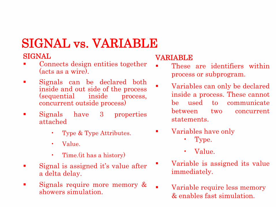
SIGNAL
Connects design entities together (acts as a wire).
Signals can be declared both inside and out side of the process (sequential inside process, concurrent outside process)
Signals have 3 properties attached
• Type & Type Attributes.
• Value.
• Time.(it has a history) Signal is assigned it‟s value after
a delta delay.
Signals require more memory & showers simulation.
VARIABLE
These are identifiers within
process or subprogram.
Variables can only be declared
inside a process. These cannot
be used to communicate
between two concurrent
statements.
Variables have only
• Type.
• Value. Variable is assigned its value
immediately.
Variable require less memory
& enables fast simulation.

SIGNAL vs. VARIABLE EXAMPLE
SIGNAL
process
begin
wait for 10 ns;
Sum1<=sum1+1;
Sum2<=sum1+1;
end process;
Time sum1 sum2
0 0 0
10 0 0
10+1delta 1 1
20 1 1
20+1 delta 2 2
30 2 2
30+1delta 3 3
VARIABLE
process
begin
wait for 10 ns;
Sum1:=sum1+1;
Sum2:=sum1+1;
end process;
Time sum1 sum2
0 0 0
10 1 2
10+1delta 1 2
20 2 3
20+1 delta 2 3
30 3 4
30+1delta 3 4

SEQUENTIAL STATEMENTS
An if- elsif- else statement selects one or none of a sequence of IF-ELSIF-ELSE STATEMENT :
events to execute.
The choice depends on one or more conditions.
If-else corresponds to when else command in the concurrent part.
if statements can be used to gene-rates prioritized structure.
if statements can be nested.
syntax: if <condition1> then
<statements>;
elsif <condition2> then <statements>;
….
else <statements>;
end if ;
SEQUENTIAL STATEMENTS (Cont..)
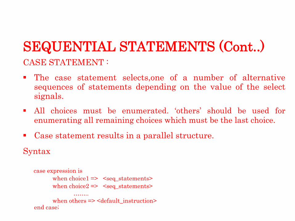
CASE STATEMENT :
The case statement selects,one of a number of alternative sequences of statements depending on the value of the select signals.
All choices must be enumerated. „others‟ should be used for
enumerating all remaining choices which must be the last choice.
Case statement results in a parallel structure.
Syntax
case expression is
when choice1 => <seq_statements>
when choice2 => <seq_statements>
…….. when others => <default_instruction>
end case;
SEQUENTIAL STATEMENTS (Cont..)
LOOP STATEMENTS
Used to iterate through a set of sequential statements.
No declaration is required explicitly for Loop identifier.
Loop identifier cannot be assigned any value within Loop.
Identifier outside the loop with the same name as loop
identifier has no effect on loop execution.
SEQUENTIAL STATEMENTS (Cont..)
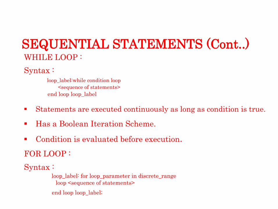
WHILE LOOP :
Syntax :
loop_label:while condition loop
<sequence of statements>
end loop loop_label
Statements are executed continuously as long as condition is true.
Has a Boolean Iteration Scheme.
Condition is evaluated before execution.
FOR LOOP :
Syntax :
loop_label: for loop_parameter in discrete_range
loop <sequence of statements>
end loop loop_label;

SEQUENTIAL STATEMENTS (Cont..)
WAIT STATEMENT :
The wait statement gives the designer the ability to suspend the sequential execution of a process or a sub-program.
The wait statement specifies the clock for a process statement that is read by synthesis tools to create sequential logic such as registers and flip-flops.
It can also be used for delaying process execution for an amount of time or to modify the sensitivity list of the process dynamically.
Three different options available for wait are
1) wait on signal 2) wait until Boolean_expr 3) wait for time_expr

SEQUENTIAL STATEMENTS (Cont..)
WAIT ON signal:
Specifies a list of one or more signals that the WAIT statement will wait for events upon.if any signal list has an event occur on it, execution continues with the statement following the wait statement.
example: WAIT ON a,b;
WAIT UNTIL expression:
Suspends execution of the process until the expression returns a value of true.
example: WAIT UNTIL (( x * 10) < 100);
WAIT FOR time_expression:
Suspends execution of the process for the time specified by the time expression.
example: WAIT FOR 10 ns;
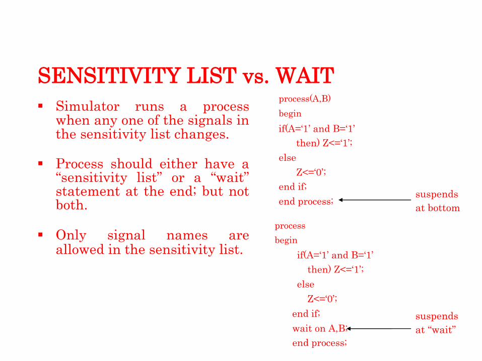
SENSITIVITY LIST vs. WAIT
Simulator runs a process when any one of the signals in the sensitivity list changes.
Process should either have a “sensitivity list” or a “wait” statement at the end; but not both.
Only signal names are allowed in the sensitivity list.
process(A,B)
begin
if(A=„1‟ and B=„1‟
then) Z<=„1‟;
else
Z<=„0‟;
end if;
end process;
process
begin
if(A=„1‟ and B=„1‟
then) Z<=„1‟;
else
Z<=„0‟;
end if;
wait on A,B;
end process;
suspends
at bottom
suspends
at “wait”

ASSERTIONS in VHDL
ASSERT STATEMENT :
Used for reporting errors when a condition is
FALSEsyntax
assert <condition>
report <message>
severity <level> ;
If condition for an assert is not met, a message with severity level is sent to user in simulator command window.
Using Assert we can,
Test prohibited signal combinations.
Test whether time constraint is being met or not.
Test if any unconnected inputs are present for the component.

SEVERITY LEVELS IN ASSERTIONS :
Note: Used as a message for debugging.
Warning: For timing violations, invalid data.
Error: Error in the behavior of the model
Failure: Catastrophic failure. Simulation is halted.
Default Severity level at which VHDL simulator should abort simulation is “ERROR” level, though it can be set
Assert is both a sequential as well as a concurrent statement
Structural Modeling

STRUCTURAL LEVEL
An entity is modeled as a set of components connected by signals, that is, as a netlist.
The behavior of the entity is not explicitly apparent from its model.
The component instantiation statement is the primary mechanism used for describing such a model of an entity.
A component instantiated in a structural description must first be declared using a component declaration.

HIERARCHICAL DESIGNS
A larger design entity can call a smaller design unit in it.
This forms a hierarchical structure.
This is allowed by a feature of VHDL called
component instantiation.
A component is a design entity in itself which is instantiated in the larger entity.
Components must be declared in the declarative part of the architecture.
Syntax : component <comp_name>
port (<port_name : <mode> <type> ); end component;

INSTANTIATION
The instance of a component
in the entity is described as
<instance_name>:<comp_name>port map (<association list>);
Example program for
following Fig is given:
entity and3gate is
port (o : out std_logic;
i1 : in std_logic;
i2 : in std_logic;
i3 : in std_logic );
end and3gate;
architecture arc_and3gate of and3gate is component andgate is
port (c : out std_logic;
a : in std_logic;
b : in std_logic);
end component;
signal temp1 :
std_logic; begin
u1: andgate
port map(temp1, i1,
i2); u2: andgate
port map(o, temp1, i3);
end arc_and3gate;
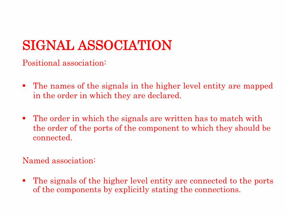
SIGNAL ASSOCIATION
Positional association:
The names of the signals in the higher level entity are mapped
in the order in which they are declared.
The order in which the signals are written has to match with
the order of the ports of the component to which they should be
connected.
Named association:
The signals of the higher level entity are connected to the ports of the components by explicitly stating the connections.

GENERICS
Generics are general mechanism used to pass information to an instance of an entity.
The most obvious and probably most used,information passed to an entity is delay times for rising and falling delays of the device being modeled.
Generic can also be used to pass any user-defined data types.
For synthesis parameters such as data path widths, signal widths, and so on can be passed in as generics.
All of the information passed to an entity is instance-specific information.
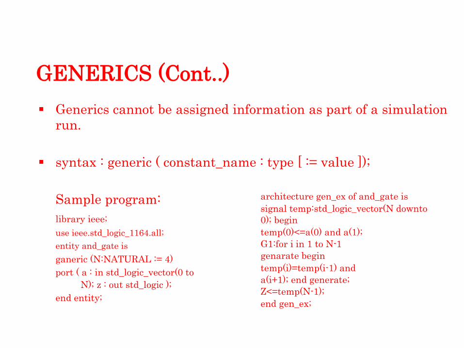
GENERICS (Cont..)
Generics cannot be assigned information as part of a simulation
run.
syntax : generic ( constant_name : type [ := value ]);
Sample program:
library ieee;
use ieee.std_logic_1164.all;
entity and_gate is
ganeric (N:NATURAL := 4)
port ( a : in std_logic_vector(0 to
N); z : out std_logic );
end entity;
architecture gen_ex of and_gate is
signal temp:std_logic_vector(N downto
0); begin
temp(0)<=a(0) and a(1);
G1:for i in 1 to N-1
genarate begin
temp(i)=temp(i-1) and
a(i+1); end generate;
Z<=temp(N-1);
end gen_ex;

GENERICS vs. CONSTANTS
Generics
• Are specified in entities.
• Hence, any change in the value of a generic affects all
architectures associated with that entity.
Constants
• Are specified in architectures.
• Hence, any change in the value of a constant will be
localized to the selected architecture only.

GENERIC IN COMPONENT
INSTANTIATIONS
syntax:
component declaration
component component-name is
generic (list-of-generics) ;
port (list-of-interface-ports);
end component ;
component instantiation statement
component-label: component-name
generic map (generic-association-
list) port map (port association-list);

CONFIGURATION
This statement selects one of several architectures for a single entity.
Components within architectures can also be chosen.
This allows use of different algo-rithms and levels of abstractions for an entity by defining different architectures.
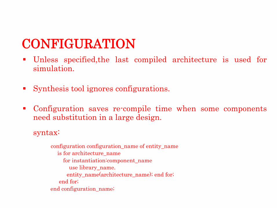
CONFIGURATION
Unless specified,the last compiled architecture is used for simulation.
Synthesis tool ignores configurations.
Configuration saves re-compile time when some components need substitution in a large design.
syntax:
configuration configuration_name of entity_name
is for architecture_name
for instantiation:component_name
use library_name.
entity_name(architecture_name); end for;
end for;
end configuration_name;

CONFIGURATION (Cont..)
entity half_adder is
Port (A,B : in bit;
Sum, carry : out
bit); end half_adder;
architecture ha_stru of half_adder
is component xor_2
Port (c,d:in bit,
e:out bit);
end component;
Component and_2
Port(l,m:in bit,
n:out bit);
end component;
begin
X1: xor_2 port map (A,B,Sum);
A1: and_2 port map(A,B,Carry);
end ha_stru;
Configuration for Half-adder entity :
Library CMOS_LIB, MY_LIB;
configuration HA_BINDING of half_adder
is for HA_stru
for X1:xor_2
use entity
cmos_lib.xor_gate(dataflow);
end for;
for A1 : and_2
use configuration
MY_LIB.and_config;
end
for; end for;
end HA_BINDING;

CONCURRENT CONSTRUCTS
All concurrent statements in an architecture are executed simultaneously.
Concurrent statements are used to express parallel activity as is the case with any digital circuit.
Concurrent statements are executed with no predefined order by the simulator. So the order in which the code is written doesn‟t have any effect on its function.
They can be used for dataflow , behavioral and structural descriptions.
Process is the only concurrent statement in which sequential statements are allowed.
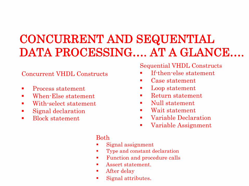
CONCURRENT AND SEQUENTIAL
DATA PROCESSING…. AT A GLANCE….
Concurrent VHDL Constructs
Process statement
When-Else statement
With-select statement
Signal declaration
Block statement
Both
Sequential VHDL Constructs
If-then-else statement
Case statement
Loop statement
Return statement
Null statement
Wait statement
Variable Declaration
Variable Assignment
Signal assignment Type and constant declaration
Function and procedure calls
Assert statement.
After delay
Signal attributes.

FSMs in VHDL

STATE MACHINE IN VHDL
Only one state machine per module.
Separate out any structural logic, e.g. muxes, counters, etc., from the state machine. Ideally only random logic should be included.
Make your state machine completely synchronous.
Asynchronous state machine need extra care when they are designed
All the flip-flop should be clocked at the same clock. Having multiple clocks will complicate the design and optimization to a great extent.
Always use dedicated clock and reset .

STATE MACHINE IN VHDL
Similarly it is extremely important that all the flip-flops recover from reset simultaneously.
Choose an optimum encoding for the state vector.(Binary and One Hot)
To improve design performance, you may divide large state machines into several small state machines and use appropriate encoding style for each.
Every state machine should have a control signal ensuring the machine in known state.

STATE MACHINE IN VHDL
To implement a state machine in VHDL, the State diagram is the only requirement..
In VHDL, each State of FSM is translated into a case in a “case-when” construct. and is simply one of the case statement branches.
State transitions are specified using “if-then-else” statements.
The set of states is generally defined as an enumerated type:
type device_states is (idle, grant_to_zero,
S5,error); signal state:device_states;

PACKAGES
It is a collection of commonly used subprograms, data types,
constants,attributes and components.
It allows designer to use shared constant or function or data type.
Packages are stored in libraries for convenience purposes.
Package consists of two parts :
Declaration
Body
“USE” statement is used to access the package.

PACKAGES
Package declaration :
package <Package_name> is
{set of declarations}
end package_name
Defines the interface for the package similar as entity(e.g.
behavior of function does not appear here, only functional
interface).
Can be shared by many design units.
Contains a set of declarations such as subprogram, type,
constant, signal, variable, etc.

PACKAGES
Package body:
package body package_name is
<declarations>; <sub
program body>;
end package_name;
Specifies the actual behavior of the package (Similar as archi-
tecture).
A Package Declaration can have only one Package body, both
having the same names. (Contrast to entity architecture)
Package Only one-to-one association Package
declaration Body

PACKAGES
Package body Contains the hidden details of a package.
Completes constant declarations for deferred constant. (Deferred
constant: constant declaration without value specified)
Is used to store private declarations that should not be visible.
If Package declaration has no function or procedure or deferred
constant declaration than no package body is required.
PACKAGES
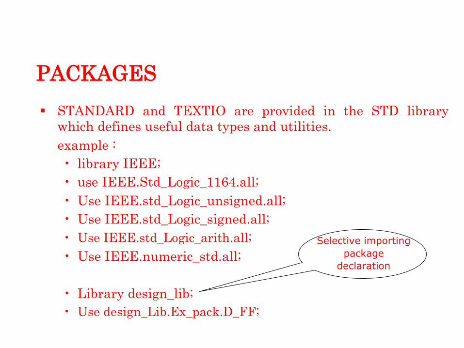
STANDARD and TEXTIO are provided in the STD library
which defines useful data types and utilities.
example :
• library IEEE; • use IEEE.Std_Logic_1164.all; • Use IEEE.std_Logic_unsigned.all; • Use IEEE.std_Logic_signed.all;
• Use IEEE.std_Logic_arith.all; • Use IEEE.numeric_std.all;
Selective importing
package
declaration
• Library design_lib; • Use design_Lib.Ex_pack.D_FF;

LIBRARY
It is an implementation-dependent storage facility for
previously analyzed design units.
Compiled VHDL design unit is saved in the work library as
default.
In order to use components and packages from a particular
library, the library and packages must be specified in VHDL
code using
Library <library_name>;
use <library_name>.<package_name>.all;

ATTRIBUTES
Attributes can be used to for modeling hardware characteristics.
An attribute provides additional information about an object (such as signals, arrays and types) that may not be directly related to the value that the object carries.
Attributes can be broadly classified as :
• Predefined - as a part of 1076 std. • Vendor Defined.
Ex:- type bit_arrayis array (1 to 5) of bit; variable L : integer := bit_array „ left; -- L takes left most bound I.e. 1
SUB PROGRAM
There are two types of subprograms in VHDL
• FUNCTION Returns a single value
• PROCEDURE Can return multiple values Although subprograms can be defined either in a package,
architecture or process it is usually defined in a package so that
they can be reused.
VHDL code is sequential inside subprograms.

SUB PROGRAM
Subprograms are termed impure if they modify or depend on
parameters not defined in their formal parameter list. ONLY
VHDL‟93 SUPPORTS IMPURE FUNCTION.
Subprograms can be called sequentially within a process or
concurrently in the architecture
A function has to be on the right hand size of a signal
assignment whereas a procedure can be called independently.

PROCEDURE
A procedure is subroutine which performs operations using all the parameters and objects, and which can change one or more of the parameters and objects in accordance with rules governing those parameters and objects.
A concurrent procedure has an implied wait statement at the end of the procedure on the signal whose mode has been declared as IN or INOUT.
A sequential procedure has no implied wait.
syntax :
procedure name ( parameter_list )
is < declarations>
begin
< statements
> end name;

FUNCTION
Unlike procedure, a function cannot change its argument and
can only return a value.
Function parameters can only be of type constant or signal.
The mode is always in. Default class is constant.
An impure function may return different values even if
theparameters are the same. Whereas a pure function
always returns the same values as parameters.
A function has to have a return statement with an expression
the value of the expression defines the result returned by the
function

FUNCTION
Syntax:
function name (parameterlist) return type
is <declarations>
begin <statements>
return
(expression); end name;
The resolution function
The resolution function resolves the value to be assigned to a signal when there are multiple drivers for the given signal.
The simulator implicitly invokes the resolution function.
The resolution function

GENERATE STATEMENT
This is a type of loop, which can be used outside the process.
Label for the loop is must.
Concurrent statements can be conditionally selected or
replicated using “generate” statement.
Used to create multiple copies of components or blocks
Provides a compact description of regular structures such as
memories, registers, and counters.

GENERATE STATEMENT
Two forms of “generate” statement
• for…generate • Number of copies is determined by a discrete range
Syntax:
label: for identifier in range generate
{concurrent_statement}
end generate [ label ]
Range must be a computable integer, in either of these forms:
• integer_expression to integer_expression • integer_expression downto integer_expression
CONCLUSION
The key advantage of VHDL when used for systems design is that it allows the behavior of the required system to be modeled and simulated before synthesis tools translate the design into real hardware (gates and wires).
VHDL allows the description of a concurrent system (many parts, each with its own sub-behavior, working together at the same time). This is unlike many of the other computing languages such as BASIC, Pascal, C, or lower-level assembly language which runs at machine code level, which all run sequentially, one instruction at a time on Von Neumann architecture.
A final point is that when a VHDL model is translated into the "gates and wires" that are mapped onto a programmable logic device such as a CPLD or FPGA, then it is the actual hardware being configured, rather than the VHDL code being "executed" as if on some form of a processor chip.

REFERENCE
Douglas L. Perry, VHDL Programming by Example ,TATA McGraw Hill.
J Bhasker, A VHDL Primer.
IEEE, IEEE Standard 1076-1993 VHDL Language Reference Manual.
Pellerin, David and Douglas Taylor, VHDL Made Easy, Prentice Hall, 1996.
Armstrong and Gray, Structured logic Design with VHDL,Prentice Hall,1996.
Internet: comp.lang.vhdl, http://www.vhdl.org.

THANK YOU