dias smart adaptive remote diagnostic ... - dias-project.com
TRANSCRIPT
DIAS
Smart Adaptive Remote Diagnostic Antitampering Systems
EUROPEAN COMMISSION
HORIZON 2020
LC-MG-1-4-2018
Grant agreement ID: 814951
Deliverable No. D4.2
Deliverable Title In-vehicular antitampering security
techniques and integration
Issue Date 31/03/2021
Dissemination level Public
Main Author(s) Genge Béla (UMFST)
Lenard Teri (UMFST)
Obaid Ur-Rehman (FEV)
Miao Zhang (FEV)
Liu Cheng (BOSCH)
Siegel Bjoern (BOSCH)
Roland Bolboacă (UMFST)
Haller Piroska (UMFST)
Ref. Ares(2021)2227326 - 31/03/2021
DIAS D4.2-In-vehicular antitampering security techniques and integration, v1.0
2 31/03/2021
Sofia Terzi (CERTH)
Athanasios Sersemis (CERTH)
Charalampos Savvaidis (CERTH)
Konstantinos Votis (CERTH)
Version v1.0

DIAS D4.2-In-vehicular antitampering security techniques and integration, v1.0
3 31/03/2021
DIAS Consortium
This project has received funding from the European Union’s Horizon 2020 research and
innovation programme under grant agreement No 814951.
This document reflects only the author's view and the Agency is not responsible for any use
that may be made of the information it contains.
DIAS D4.2-In-vehicular antitampering security techniques and integration, v1.0
4 31/03/2021
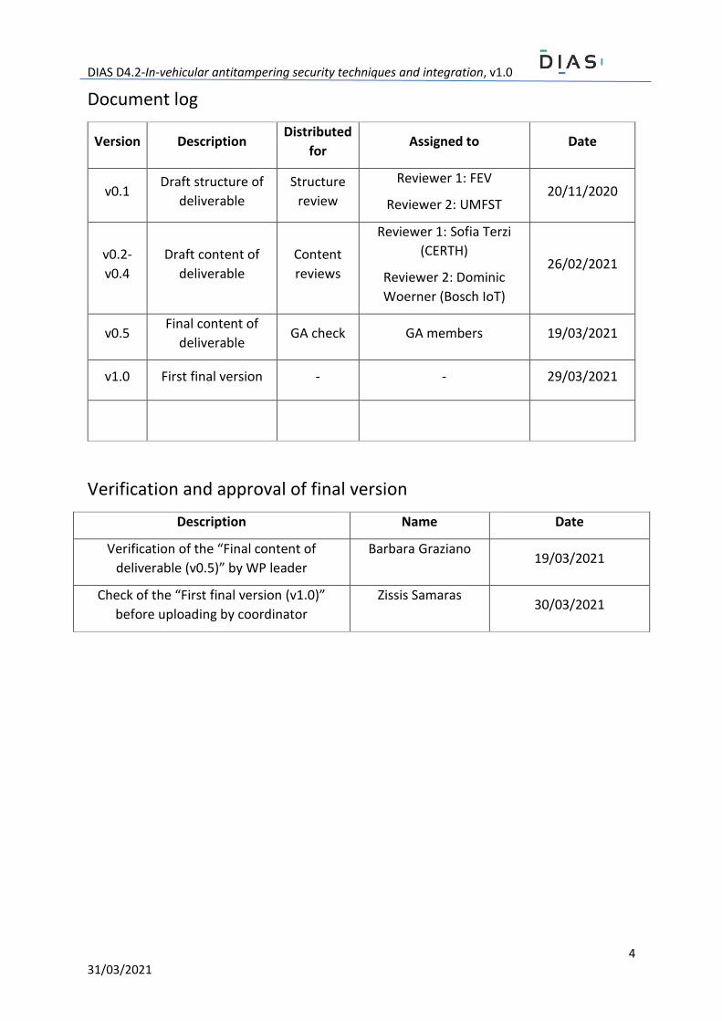
Document log
Version Description Distributed
for Assigned to Date
v0.1 Draft structure of
deliverable
Structure
review
Reviewer 1: FEV
Reviewer 2: UMFST 20/11/2020
v0.2-
v0.4
Draft content of
deliverable
Content
reviews
Reviewer 1: Sofia Terzi
(CERTH)
Reviewer 2: Dominic
Woerner (Bosch IoT)
26/02/2021
v0.5 Final content of
deliverable GA check GA members 19/03/2021
v1.0 First final version - - 29/03/2021
Verification and approval of final version
Description Name Date
Verification of the “Final content of
deliverable (v0.5)” by WP leader
Barbara Graziano 19/03/2021
Check of the “First final version (v1.0)”
before uploading by coordinator
Zissis Samaras 30/03/2021
DIAS D4.2-In-vehicular antitampering security techniques and integration, v1.0
5 31/03/2021
Executive summary Modern vehicles are equipped with dozens of Electronic Control Units (ECUs), digital sensors, and
communication systems, which provide innovative functions. As a result, pollutant emissions have
reduced significantly. However, with these advancements, tamperers have also found new ways to
exploit digital communication systems, which can significantly elevate the tail-pipe emissions.
The DIAS project, funded by the EU Research and Innovation program Horizon 2020, aims to reduce,
or totally eliminate tampering techniques that relate to vehicle emissions, by means of protective
hardware and software solutions. This report serves as a description of the security techniques
explored within the DIAS project, which could be used to alleviate tampering attempts. The document
provides an overview of security techniques, and of possible directions mentioned in prior
deliverables, namely in Deliverable 2.2 - End-user requirements & use case definitions, Deliverable 3.2
- Status quo of critical tampering techniques and proposal of required new OBD monitoring
techniques, and Deliverable 4.1 - Security analysis, requirements identification and applicability of
security solutions for tampering detection. Accordingly, three directions are identified and later
detailed: communication security, component security, and firewall & intrusion detection systems.
For each of the three security directions, specific security techniques are explored and detailed. In
terms of communication security, the use of Secure CAN, denoting security of communications
according to the techniques outlined in AUTOSAR Specification of Secure Onboard Communication
standard (AUTOSAR SecOC), may address most existing tampering attempts. On the other hand, the
document also acknowledges that the adoption of SecOC for all communications is not feasible,
especially in the case of communications involving digital sensors. Therefore, in this direction the
deliverable describes several techniques that may address the computational limitations of digital
sensors.
The component security, on the other hand, describes several techniques for cryptographic key
distribution. To this end, it needs to be acknowledged that the vehicle comprises various components
with different computational capabilities. As a result, the deliverable describes several key distribution
techniques that leverage a wide variety of cryptographic constructions that range from simple
techniques including cryptographic hash functions to more advanced public key cryptography.
Subsequently, the document also briefly mentions the secure boot, secure firmware update, and
address randomization as necessary techniques for securing critical in-vehicle components.
The firewall & intrusion detection systems (IDS) are described in detail. Both components build on a
common rule processing engine that takes a set of rules and applies them on CAN frames. The firewall
component has been developed as a two-dimensional software module. A first module has been
designed to process CAN frames, while the second module has been designed to process traditional
IP packets. Conversely, the IDS component has been specifically designed to analyze CAN frames, and
to detect tampering based on CAN frame signatures.
The document also provides implementation details for several components, alongside experimental
results. It should be noted, however, that since this deliverable is related to Task 4.2, which will
complete in month 30 of the project, the described results should be viewed as intermediate. Also,
the project partners intend to explore other directions as well in order to refine/adapt the developed
techniques.
DIAS D4.2-In-vehicular antitampering security techniques and integration, v1.0
6 31/03/2021

DIAS D4.2-In-vehicular antitampering security techniques and integration, v1.0
7 31/03/2021
Contents Executive summary 5
Contents 7
List of Abbreviations 10
List of Definitions 12
List of Figures 14
List of Tables 15
1 Introduction 16
1.1 Background 16
1.2 Purpose of the document 16
1.3 Document structure 17
1.4 Deviations from original DoW 17
1.4.1 Description of work related to deliverable as given in DoW 17
1.4.2 Time deviations from original DoW 17
1.4.3 Content deviations from original DoW 17
2 System architecture and security goals 18
2.1 Architecture 18
2.2 Security goals and explored directions 20
2.3 In-vehicle security architecture 21
3 Cryptographic key management 22
3.1 Brief overview of main cryptographic techniques 23
3.2 Key management for xCUs 23
3.2.1 Basic setup 23
3.2.2 Secure key generation and storage 24
3.2.3 Secure key distribution 24
Long-term key distribution protocol (Proto-LTK) 25
Session key distribution protocol (Proto-SK) 25
Formal analysis 26
3.3 Key management for xCUs from different suppliers 26
3.3.1 Diffie-Hellman and Elliptic Curve Diffie-Hellman key exchange 27
Diffie-Hellman (DH) key exchange 27
Elliptic Curve Diffie-Hellman (ECDH) key exchange 29
3.3.2 Key distribution of the pre-shared random numbers 29
During production 30
In workshop 30
3.3.3 Authentication of the flashing tool 31
DIAS D4.2-In-vehicular antitampering security techniques and integration, v1.0
8 31/03/2021
3.4 Key management for CAN-based digital sensors 32
3.4.1 Bootstrapping 32
3.4.2 Generating fresh group keys 33
3.4.3 Synchronization protocol 33
4 Secure data exchange 34
4.1 Secure CAN and SecOC Light 34
4.2 Secure SENT 37
4.2.1 General description of the SENT protocol 37
4.2.2 The Secure SENT protocol 38
4.3 MixCAN: Mixed message signatures for CAN 40
4.3.1 Signature aggregation 40
4.3.2 Secure filter construction 41
4.3.3 Synchronization 42
4.3.4 Signature verification 42
4.4 Secure transfer of certificates and tester authentication 42
4.5 Secure firmware update, secure boot, and address randomization 45
4.5.1 Secure firmware update 45
4.5.2 Secure boot 45
4.5.3 Address Space Layout Randomization 46
Main concept 46
ASLR on xCUs 47
5 Firewall and intrusion detection systems 47
5.1 CAN frame rule processing engine 48
5.2 Firewall 50
5.3 Intrusion detection system 51
6 Prototype integration and experimentation 52
6.1 Prototype implementations 52
6.1.1 Key generation and distribution for xCU to xCU communication 52
6.1.2 Enhanced SecOC 52
6.1.3 Firewall and intrusion detection 54
6.2 Developed testbed for demonstrating the security features 56
6.3 Experiment setup 57
6.3.1 Firewall and IDS rule creation 58
6.3.2 Secure Logging setup 59
6.4 Experimental results 59
6.5 Demonstration of the Tester Device Authentication 61

DIAS D4.2-In-vehicular antitampering security techniques and integration, v1.0
9 31/03/2021
6.5.1 Establish Enhanced SecOC 61
6.5.2 Service Extension 63
Conclusions 65
References 67
A. Annex: Formal analysis of cryptographic protocols 70
B. Annex: TPM interface implementation details 73
C. Annex: Firewall/IDS API 74
D. Annex: X.509 Certificates for tester devices 75
E. Annex: Enhanced SecOC API, tools and measurements 78

DIAS D4.2-In-vehicular antitampering security techniques and integration, v1.0
10 31/03/2021
List of Abbreviations 2TDEA Two-key Triple Data Encryption Algorithm
3TDEA Three-key Triple Data Encryption Algorithm
AES Advanced Encryption Standard
ASIC Application Specific Integrated Circuit
ASLR Address Space Layout Randomization
CAN Controller Area Network
CCU Connectivity Control Unit
CID CAN Identifier
CMAC Cipher-based Message Authentication Code
CRL Certificate Revocation List
CSR Certificate Signing Request
DH Diffie-Hellman
EBF Encrypted Bloom Filter
ECU Engine Control Unit
ECDH Elliptic Curve Diffie-Hellman
EPS Environmental Protection System
FC Fast Channels
HSM Hardware Security Module
ID Identifier
IDS Intrusion Detection System
ICT Information and Communications Technology
ISO International Standardization Organization
IoT Internet of Things
IP Internet Protocol
JSON JavaScript Object Notation
JWT JSON web token
KDF Key Derivation Function
KDK Key Distribution Key
KSK Key Signing Key
LIN Local Interconnect Network
LOKI Lightweight Cryptographic Key Distribution Protocol
MAC Message Authentication Code
DIAS D4.2-In-vehicular antitampering security techniques and integration, v1.0
11 31/03/2021
MacAddress Media Access Control Address
NAT Network Address Translation
NIST National Institute of Standards and Technology
NOx Nitrogen Oxides
OBD On-board Diagnostics
OEM Original Equipment Manufacturer
PDU Protocol Data Unit
PM Particulate Matter
Proto-LTK Long-term key distribution protocol
Proto-SK Session key distribution protocol
PWM Pulse Width Modulation
RA Registration Authority
RFC Request for Comments
RoT Root of Trust
RTM Root of Trust for Measurement
RTR Root of Trust for Reporting
RTS Root of Trust for Storage
SAE J1939 Society of Automotive Engineers standard SAE J1939
SBF Secure Bloom Filter
SC Slow Channels
SP Service Provider
SCR Selective Catalytic Reduction
SCU Sensor Control Unit
SecOC (light) Secure Onboard Communication
SENT Single Edge Nibble Transmission
SM Security Module
SRK Storage Root Key
TLS Transport Layer Security
TPM Trusted Platform Module
xCU Electronic Control Unit, Any Control Unit
XML eXtensible Markup Language
DIAS D4.2-In-vehicular antitampering security techniques and integration, v1.0
12 31/03/2021
List of Definitions Attack vector: Approach, or the sequence of steps used by an attacker to gain access to the target system.
Attacker: An individual who attempts to access the vehicle’s network, mostly without the owner’s consent.
Authentication: Verifying the identity of a person or a communication partner.
Blacklisting: An access control mechanism, the opposite of whitelisting, which ensures that the elements in the list are denied access. In the case of the DIAS project, the blacklisting term is used to denote the CAN frames that are blocked by the firewall.
Bloom filter: A probabilistic data structure that offers a space-efficient representation for a set of items.
Cryptoperiod: The time span during which a cryptographic key is authorized for use.
Data authentication: The process of verifying the origin and integrity of data.
Data integrity: The receiver of data must have the assurance that the data has come intact from the intended sender and not changed intentionally and unintentionally.
Defence in depth: The positioning of multiple layers of security techniques.
Firewall: A software module that monitors the network traffic (in the case of the DIAS project both CAN, and IP communications), and uses a set of rules to control incoming and outgoing traffic.
Key derivation function: A function implementing an algorithm that generates new cryptographic keys based on a cryptographic key usually known as the master, or the key derivation key.
Key distribution key: A long-term symmetric key used to encrypt session keys.
Key signing key: A pair of public-private keys used to digitally sign the messages in key distribution protocols.
Long-term key: Cryptographic key with a longer cryptoperiod, usually used to distribute session keys.
Non repudiation: The assurance that one cannot deny something. In cryptography, non-repudiation means a security service that provides proof of the integrity and origin of data.
Secure logging: The generated logs are signed via a secret key.
Security controller: Specialized cryptographic co-processor (hardware chip) capable of executing cryptographic operations in a secure manner, isolated from the main processing unit.
Short-term key: Cryptographic key with a short cryptoperiod, used in data protection schemes (e.g., data authentication).
Session Key: A short-term symmetric key used to provide data authentication.
Storage root key: A pair of public-private keys embedded in the TPM and used to protect the keys that are stored outside the TPM.
Tamperer: A person who intentionally, illegally and for whatever reason alters an EPS, resulting in increased emissions.
Trusted platform module: A security controller that is compliant with the TPM 2.0 specification.
DIAS D4.2-In-vehicular antitampering security techniques and integration, v1.0
13 31/03/2021
Intrusion detection system: In the case of the DIAS project, it is a software module that monitors the network traffic (e.g., CAN frames), and uses a signature database (i.e., rule file) to detect malicious activity.
Whitelisting: It is an access control mechanism, the opposite of blacklisting, which ensures that the elements in the list are permitted. In the case of the DIAS project, the whitelisting term is used to denote the CAN frames that are permitted to pass through by the firewall.

DIAS D4.2-In-vehicular antitampering security techniques and integration, v1.0
14 31/03/2021
List of Figures Figure 1: Simplified architecture of the modern vehicle from the perspective of the components
significant for the DIAS project. ............................................................................................................ 19
Figure 2: Relation with previous deliverables. ...................................................................................... 19
Figure 3: In-vehicle security architecture and security components (limited to the scope of the DIAS
project, namely to the security of the EPS). ......................................................................................... 22
Figure 4: Basic setup of the key distribution scheme in xCU to xCU communication. ......................... 23
Figure 5: Summary of xCU to xCU key distribution protocols. ............................................................. 26
Figure 6: Diffie-Hellman key exchange between an ECU and a SCU. ................................................... 28
Figure 7: Key distribution during production. ....................................................................................... 30
Figure 8: Key distribution in workshop. ................................................................................................ 31
Figure 9: The service tester requests an update with authentication. ................................................. 31
Figure 10: Summary of the LOKI protocol(s). ........................................................................................ 32
Figure 11: CAN data frame format. ....................................................................................................... 35
Figure 12: SecOC Light authentication concept. ................................................................................... 36
Figure 13: Example SecOC Light MAC calculation................................................................................. 37
Figure 14: An example of a typical message in the Fast Channel. ........................................................ 37
Figure 15: An example of a typical message in the Slow Channel. ....................................................... 38
Figure 16: SENT Authentication Concept. ............................................................................................. 39
Figure 17: An example of the MAC Calculation. ................................................................................... 40
Figure 18: MixCAN’s architecture. ........................................................................................................ 41
Figure 19: Tester X.509 Certificate Overall Flow .................................................................................. 44
Figure 20: Stateful firewall and Intrusion detection system architecture, alongside a TPM. .............. 47
Figure 21: Rule processing engine implemented as part of the Firewall and the Intrusion Detection
System. .................................................................................................................................................. 48
Figure 22: Processing of rules and action results in the case of the two phases. ................................ 50
Figure 23: Tester Authenticated Communication with xCU. ................................................................ 53
Figure 24: The physical testbed at UMFST partner’s premises used to demonstrate the main features
of the Firewall and IDS, both equipped with TPM capabilities (e.g., key generation, secure logging). 57
Figure 25: Data Flow Diagram illustrating the interacting components used throughout the
experiments. ......................................................................................................................................... 58
Figure 26: Establish OBD connection. ................................................................................................... 62
Figure 27: CCU (center screen) speaks only to xCU (screen on the right) with Enhanced SecOC. ....... 62
Figure 28: CCU (center screen) speaks only to the tester (left screen) with Enhanced SecOC. ........... 62
Figure 29: Service extension. ................................................................................................................ 63
Figure 30: Confirm choice to the OBD tool. .......................................................................................... 63
Figure 31: Message flow for deleting one error code. ......................................................................... 64
Figure 32: Message flow for deleting all error codes. .......................................................................... 64
Figure 33: Message flow for exit. .......................................................................................................... 64
Figure 34: X.509 Issuance...................................................................................................................... 76
Figure 35: X.509 Verification. ................................................................................................................ 77
Figure 36: In vehicle errors. .................................................................................................................. 78
Figure 37: Error History for specific vehicle. ......................................................................................... 79
Figure 38: Notifications Tab. ................................................................................................................. 79
Figure 39: Overall message flow Enhanced SecOC. .............................................................................. 81
DIAS D4.2-In-vehicular antitampering security techniques and integration, v1.0
15 31/03/2021
List of Tables
Table 1: Diffie-Hellman key exchange parameters. .............................................................................. 28
Table 2: Comparison of key sizes. ......................................................................................................... 29
Table 3: ECDH key exchange parameters. ............................................................................................ 29
Table 4: Computed payload [MIN, MAX] intervals for each byte. ........................................................ 58
Table 5: Measurements related to the performance of the stateful firewall. ..................................... 61
Table 6: Measurements related to the performance of the implemented Intrusion Detection
component. ........................................................................................................................................... 61
Table 7: Example regarding the CSR ..................................................................................................... 75
Table 8: Example regarding the X.509 Certificate ................................................................................ 76
Table 9: API Endpoints .......................................................................................................................... 78
Table 10: Server specifications ............................................................................................................. 80
Table 11: TesterNode Metrics ............................................................................................................... 80
Table 12: CCU metrics ........................................................................................................................... 80
Table 13: ECU metrics ........................................................................................................................... 80
DIAS D4.2-In-vehicular antitampering security techniques and integration, v1.0
16 31/03/2021
1 Introduction
1.1 Background
Modern vehicles contain dozens of Control Units, each one controlling a wide range of functionalities
(e.g., infotainment, braking, engine). Furthermore, each generation brings newer and richer functions,
also increasing the size of the code and the level of sophistication in terms of communication,
protocols, and software capabilities. Since each Control Unit has its own purpose, in this document
we use the abbreviation ECU to denote the Engine Control Unit, and xCU to refer to general purpose
control units, excluding the Sensor Control Unit (SCU).
While this technological advancement has brought upon a wide range of advantages and integrated
features, it also exposed modern vehicles to significant threats. As demonstrated by many recent
scenarios [Urquhart2019, Takefuji2018], vehicle digital communication systems can be exploited in a
way that alters the vehicle’s behavior in order to gain certain advantages (e.g., financial, performance),
or, in more extreme cases, to cause physical damage. Subsequently, changes in the vehicle’s
parameters, and the connection of sensor emulators (e.g., AdBlue emulators), can significantly alter
the operation of the vehicle’s internal subsystems. Such changes, also known as tampering, can
deactivate critical systems such as the Selective Catalytic Reduction (SCR) dosing system. As a result,
this effectively stops the injection of the AdBlue fluid, which essentially translates to higher NOx
emissions. While this reduces the costs of the vehicle’s maintenance, it has a dramatic environmental
impact.
Consequently, heavy duty vehicle manufacturers call for action in order to prevent aftermarket
manipulations [Acea2017]. As a response to these issues, the DIAS project, funded by the EU Research
and Innovation program Horizon 2020, aims to reduce, or totally eliminate tampering techniques that
relate to vehicle emissions, by means of protective hardware and software solutions. In particular,
Deliverable 4.2 documents the explored security techniques addressing tampering.
It should be noted that the scope of this document in terms of security is only related to digital
communications. Consequently, the security of data exchanges involving analog components is
considered out of scope.
1.2 Purpose of the document
This document serves as a description of the explored techniques for alleviating tampering attempts
from a cyber security perspective as described mainly in Task 4.2 (Development of in-vehicle security
mechanisms). The work builds on the prior results documented in Deliverables 2.2 (End-user
requirement & use case definition), 3.2 (Status quo of critical tampering techniques and proposal of
required new OBD monitoring techniques), and 4.1 (Security analysis, requirements identification and
applicability of security solutions for tampering protection).
It should be noted that this deliverable is related to Task 4.2, which will complete in month 30 of the
project. Therefore, the described results should be viewed as intermediate, and that the project
partners intend to further explore other directions, and to refine/adapt the developed techniques
according to the experimental results, the results of the hackathon events, and the integration tests
that will follow.
DIAS D4.2-In-vehicular antitampering security techniques and integration, v1.0
17 31/03/2021
1.3 Document structure
The techniques that are currently investigated within the DIAS project for achieving in-vehicle security
against tampering are documented in Sections 3, 4, and 5. Nevertheless, as already mentioned, the
consortium intends to further explore other techniques as well, and may revise (i.e., refine/adapt) the
techniques documented in this work. The document is structured as follows.
Section 1 presents the background, the purpose, and the document structure. Next, Section 2 provides
a general overview of the internal vehicle architecture in terms of control units, sensors, and
communication subsystems. The architecture focuses on the main elements, which play a significant
role in the implementation of the Environmental Protection System (EPS). The same section continues
with an overview of the main objectives for achieving cyber security protection against tampering.
Section 3 documents the cryptographic key management techniques for various scenarios. This is
followed by Section 4, where the techniques for achieving secure data exchanges are documented.
Next, Section 5 describes the firewall and intrusion detection systems, and Section 6 provides
prototype integration and experimentation results. The conclusions are presented in Section 7.
1.4 Deviations from original DoW
1.4.1 Description of work related to deliverable as given in DoW In-vehicular antitampering security techniques and integration: discuss the security mechanisms
developed for providing security inside the vehicle (e.g., sensor security, secure CAN, stateful firewall,
intrusion detection).
1.4.2 Time deviations from original DoW According to the approved extension, the deliverable is not delayed.
1.4.3 Content deviations from original DoW Compared to the original DoW there have been no deviations in terms of content.
DIAS D4.2-In-vehicular antitampering security techniques and integration, v1.0
18 31/03/2021
2 System architecture and security goals
2.1 Architecture
In today's modern vehicle the communication is based primarily on the Controller Area Network
(CAN). Standardised in 2003 [ISO2003], it is an International Standardization Organization (ISO) -
defined communications bus that describes the rules for exchanging data frames between devices.
Given its limitations mainly in terms of bandwidth and payload size, recently, two main improved
communication infrastructures have been proposed. The CAN+ protocol was proposed by Ziermann,
et al. in 2009 [Ziermann2009], and it exploits the time between transmissions to send additional data.
More recently, in 2012, Robert Bosch GmbH developed the CAN with flexible data-rate protocol (CAN-
FD) [RBGmbh2012], which brings notable advantages over CAN and CAN+. The most significant are
higher bandwidth and larger payload.
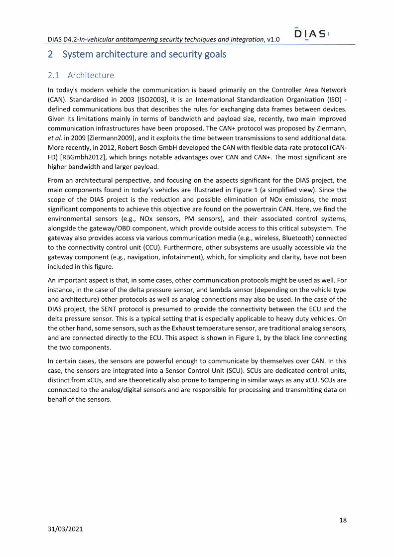
From an architectural perspective, and focusing on the aspects significant for the DIAS project, the
main components found in today’s vehicles are illustrated in Figure 1 (a simplified view). Since the
scope of the DIAS project is the reduction and possible elimination of NOx emissions, the most
significant components to achieve this objective are found on the powertrain CAN. Here, we find the
environmental sensors (e.g., NOx sensors, PM sensors), and their associated control systems,
alongside the gateway/OBD component, which provide outside access to this critical subsystem. The
gateway also provides access via various communication media (e.g., wireless, Bluetooth) connected
to the connectivity control unit (CCU). Furthermore, other subsystems are usually accessible via the
gateway component (e.g., navigation, infotainment), which, for simplicity and clarity, have not been
included in this figure.
An important aspect is that, in some cases, other communication protocols might be used as well. For
instance, in the case of the delta pressure sensor, and lambda sensor (depending on the vehicle type
and architecture) other protocols as well as analog connections may also be used. In the case of the
DIAS project, the SENT protocol is presumed to provide the connectivity between the ECU and the
delta pressure sensor. This is a typical setting that is especially applicable to heavy duty vehicles. On
the other hand, some sensors, such as the Exhaust temperature sensor, are traditional analog sensors,
and are connected directly to the ECU. This aspect is shown in Figure 1, by the black line connecting
the two components.
In certain cases, the sensors are powerful enough to communicate by themselves over CAN. In this
case, the sensors are integrated into a Sensor Control Unit (SCU). SCUs are dedicated control units,
distinct from xCUs, and are theoretically also prone to tampering in similar ways as any xCU. SCUs are
connected to the analog/digital sensors and are responsible for processing and transmitting data on
behalf of the sensors.

DIAS D4.2-In-vehicular antitampering security techniques and integration, v1.0
19 31/03/2021
Figure 1: Simplified architecture of the modern vehicle from the perspective of the components significant for the DIAS project.
Figure 2: Relation with previous deliverables.
From an architectural and cyber security perspective, it becomes clear that the gateway plays a critical
role in enforcing anti-tampering measures. In fact, this component plays a crucial role since it is
positioned at the intersection between most vehicle’s communication subsystems. On the other hand,
the component is in a privileged position by having access to several communication subsystems. Its
positioning gives direct access to all data exchanges, and thus provides support for the
implementation of advanced security techniques (e.g., intrusion detection), which require deep
packet inspection and access to different data flows.
Obviously, and, as underlined by previous deliverables such as D4.1 “Security analysis, requirements
identification and applicability of security solutions for tamper protection”, its privileged position
makes the gateway susceptible to tampering attempts. The risk analysis conducted in D4.1 showed
that an attacker with basic knowledge about vehicle communications, and with access to the OBD
port, can inject commands that change the vehicle’s behaviour, and effectively disable the EPS. In light
of these prior findings, it becomes imperative to enforce secure access policies by leveraging and
DIAS D4.2-In-vehicular antitampering security techniques and integration, v1.0
20 31/03/2021
adapting traditional/existing cyber security techniques, which can increase the level of sophistication
required to illegally alter vehicle parameters. Furthermore, in specific tampering scenarios, the
implemented measures may also render tampering attempts ineffective, thus drastically reducing the
possible attack vectors that may be used by future tamperers.
2.2 Security goals and explored directions
The applicable security techniques explored by the DIAS project have been detailed in previous
deliverables, especially in D4.1, but also briefly in D2.2 and D3.2 (see Figure 2). However, for the sake
of completeness and clarity of presentations, these are briefly outlined in the remainder of this
section.
In terms of end-user security techniques, three categories are defined:
1. Communication security.
2. Component security.
3. Firewall and intrusion detection systems.
A major concern regarding modern in-vehicle communications is the lack of protective measures. To
this end, communications are mainly carried over the CAN bus, where the broadcast pattern gives
access to all data exchanges for any entity connected to this bus. As a result, malicious actors (e.g.,
tampering devices) may easily access data exchanges between critical xCUs, including the components
involved in the EPS. The lack of fundamental security techniques also means that these malicious
entities may also alter data, inject new frames, and interfere with the vehicle’s normal operation.
Consequently, the DIAS project identified, as a first security goal: securing communications between
xCUs. More specifically, the need to provide verifiable data integrity for in-vehicle data transfers was
identified as a fundamental security goal. The following are some of the techniques that could be used
to address this goal, however, others may be also explored throughout the duration of the project to
achieve the same goal:
- Authentication of data transfers.
- Where feasible, secure key generation, exchange, and storage on end nodes should be
implemented.
The second security goal concerns the security of components found within vehicles (e.g., xCUs/ECUs
and digital sensors). Here, it was acknowledged that, in order to benefit from the advanced features
offered by modern cryptographic schemes, where feasible, and especially in the case of xCUs/ECUs it
is necessary to use security controllers. A security controller is physically separated from the main
processor, and it provides cryptographic operations with advanced algorithms. A key advantage of
security controllers is the protection of sensitive data (e.g., cryptographic keys, passwords), and their
resistance to tampering (logical and physical). Besides this, and supported by security controllers, the
following techniques have been identified as applicable for securing xCUs/ECUs:
- Where applicable, secure key generation, exchange, and storage.
- Secure boot, secure software update.
- Firmware integrity and authenticity.
- Authentication of communication endpoints.
- Data authenticity and integrity (via authenticity).
In terms of securing digital sensors, where feasible, the security goals include the following:
- Authentication of data transfers.
- Integrity protection of data transfers (via authenticity).
DIAS D4.2-In-vehicular antitampering security techniques and integration, v1.0
21 31/03/2021
Lastly, the third category includes the monitoring and detection components. In particular, the project
envisions that adapted variants of the firewall and intrusion detection components commonly found
in traditional ICT systems, and their integration into modern vehicles, may bring numerous benefits.
Firewalls are essential elements in the establishment of in-depth defensive strategies. These are able
to enforce filtering rules and play the role of “actuators” in dynamic security systems. In terms of
intrusion detection, the DIAS project envisions a component that can perform packet inspection,
analysis of communication patterns in order to detect deviations and intrusion attempts.
For this last category, the following security techniques have been identified:
- White-listing and black-listing of data exchanges.
- Packet inspection at critical layers.
- Analysis of communication patterns according to a predefined set of rules.
- Secure logging of detected events.
2.3 In-vehicle security architecture
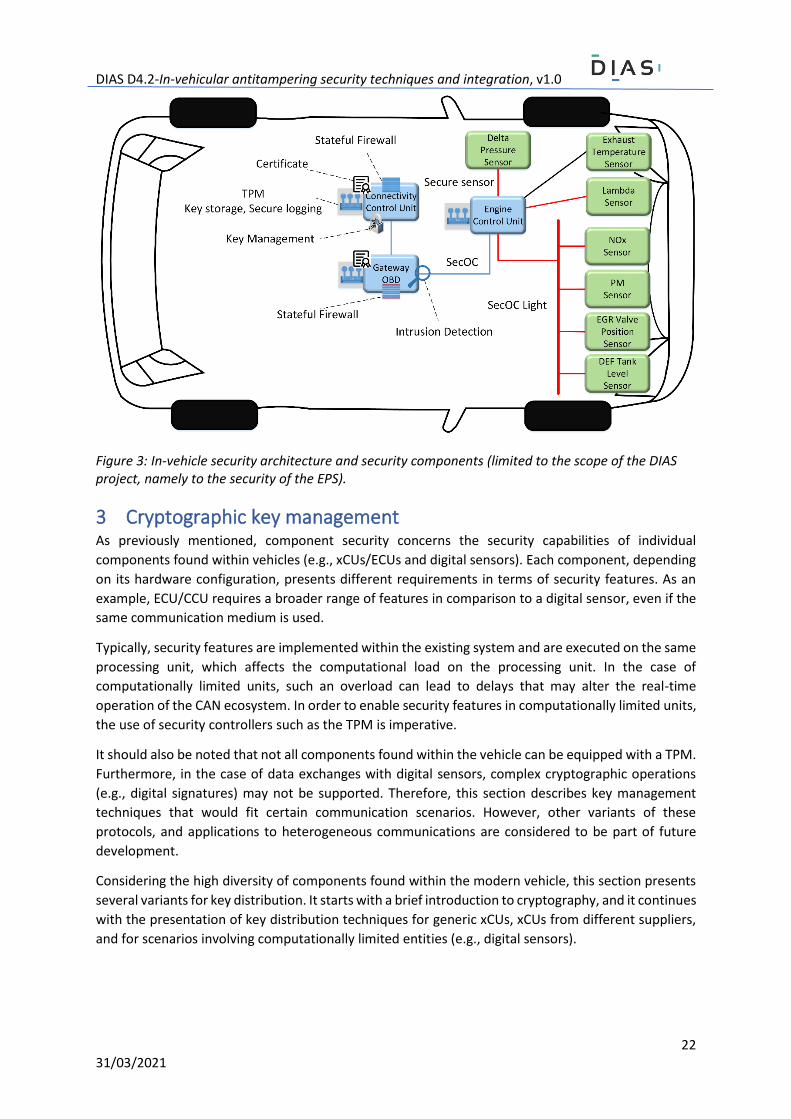
According to the previously mentioned security techniques and main goals, the in-vehicle security
architecture may comprise additional protocols, security modules, and independent components. An
overview this architecture is shown in Figure 3.
As a response to threats, attack vectors, overall security requirements, particular limitations and
concerns of the automotive industry, the in-vehicle security architecture follows an adapted design
based on the available solutions from the field of traditional ICT systems. The architecture is
conceptualized by following the “defence in depth principles”, where various security constructions
are harmonized to yield a comprehensive in-vehicle security solution. The architecture also adheres
to the principles for securing communications, as outlined by the AUTOSAR Specification of Secure
Onboard Communication standard (AUTOSAR SecOC) [Autosar2017].
As shown in Figure 3, the in-vehicle security architecture enhances the traditional vehicle architecture
(shown in Figure 1) with additional hardware components, software modules, and secure
communications. In terms of additional hardware modules, the architecture highlights the security
controller (i.e., TPM), which provides cryptographic constructions with advanced cryptographic
algorithms and protocols. To this end, Trusted Platform Module (TPM) 2.0 - compatible security
controllers represent tamper-proof cryptographic co-processors capable of executing cryptographic
operations in a secure manner, isolated from the main processing unit. In the remainder of this
document the TPM abbreviation is used to denote a security controller compatible with the TPM 2.0
specification. We note that the discussion related to the actual hardware integration of TPM with xCUs
is considered out of scope.
Subsequently, the architecture embodies software modules such as the stateful firewall, intrusion
detection, and key management, which provide the fundamental capabilities to enforce security
policies, and to detect intrusion attempts. Lastly, the glue between all these security-enhanced
components is the secure data exchange, made possible via the secure CAN and secure digital sensor
communication. It should be noted that throughout this document “secure CAN” refers to the
AUTOSAR Specification of Secure Onboard Communication standard (AUTOSAR SecOC)
[Autosar2017]. The architecture also depicts other features (e.g., secure logging, digital certificates),
and different variants of the SecOC protocol, which are detailed later in this document.
DIAS D4.2-In-vehicular antitampering security techniques and integration, v1.0
22 31/03/2021
Figure 3: In-vehicle security architecture and security components (limited to the scope of the DIAS project, namely to the security of the EPS).
3 Cryptographic key management As previously mentioned, component security concerns the security capabilities of individual
components found within vehicles (e.g., xCUs/ECUs and digital sensors). Each component, depending
on its hardware configuration, presents different requirements in terms of security features. As an
example, ECU/CCU requires a broader range of features in comparison to a digital sensor, even if the
same communication medium is used.
Typically, security features are implemented within the existing system and are executed on the same
processing unit, which affects the computational load on the processing unit. In the case of
computationally limited units, such an overload can lead to delays that may alter the real-time
operation of the CAN ecosystem. In order to enable security features in computationally limited units,
the use of security controllers such as the TPM is imperative.
It should also be noted that not all components found within the vehicle can be equipped with a TPM.
Furthermore, in the case of data exchanges with digital sensors, complex cryptographic operations
(e.g., digital signatures) may not be supported. Therefore, this section describes key management
techniques that would fit certain communication scenarios. However, other variants of these
protocols, and applications to heterogeneous communications are considered to be part of future
development.
Considering the high diversity of components found within the modern vehicle, this section presents
several variants for key distribution. It starts with a brief introduction to cryptography, and it continues
with the presentation of key distribution techniques for generic xCUs, xCUs from different suppliers,
and for scenarios involving computationally limited entities (e.g., digital sensors).
DIAS D4.2-In-vehicular antitampering security techniques and integration, v1.0
23 31/03/2021
3.1 Brief overview of main cryptographic techniques
Cryptographic techniques are typically divided into two generic types: symmetric and asymmetric
[Menezes2001]. An encryption scheme is said to be symmetric if for each associated
encryption/decryption key pair, it is computationally ‘easy’ to determine one key knowing only the
other key. Mostly, the two keys are a single common key, therefore the term symmetric key is used.
On the contrary, asymmetric-key cryptography, also known as public-key cryptography, is a
cryptographic scheme in which for any pair of associated encryption/decryption keys, given the
encryption key, it is computationally infeasible to determine the corresponding decryption key.
Considering this property, public-key cryptography is used for transmitting messages over insecure
communication channels. Two separate keys are required, the public key used to encrypt the message
needs not to be kept secret, whereas only the private key used to decrypt the message must be kept
secure and secret. By knowing the public key, it is computationally difficult to deduce the private key
and thus to decrypt the message. The well-known public-key cryptography systems are the Diffie-
Hellman key exchange (named after its inventors, W. Diffie, and M. Hellman [DH1976]), RSA (named
after its inventors, R. Rivest, A. Shamir, and L. Adleman [RSA1978]), ElGamal (named after its inventor,
T. Elgamal [ElGamal1985]), among others.
3.2 Key management for xCUs
3.2.1 Basic setup The secure exchange of any type of data requires cryptographic keys to enforce fundamental security
properties such as data authenticity and confidentiality. Such cryptographic keys need to be generated
and periodically distributed to end-points. Furthermore, various security constructions explored by
the DIAS project may also require different keys to be used in independent scenarios. Consequently,
a generic approach has been developed for generating and distributing cryptographic keys between
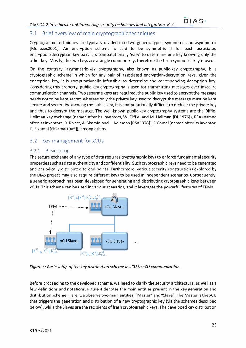
xCUs. This scheme can be used in various scenarios, and it leverages the powerful features of TPMs.
Figure 4: Basic setup of the key distribution scheme in xCU to xCU communication.
Before proceeding to the developed scheme, we need to clarify the security architecture, as well as a
few definitions and notations. Figure 4 denotes the main entities present in the key generation and
distribution scheme. Here, we observe two main entities: “Master” and “Slave”. The Master is the xCU
that triggers the generation and distribution of a new cryptographic key (via the schemes described
below), while the Slaves are the recipients of fresh cryptographic keys. The developed key distribution
DIAS D4.2-In-vehicular antitampering security techniques and integration, v1.0
24 31/03/2021
scheme, in the case of xCU to xCU communications, leverages public key cryptography, and several
types of symmetric keys.
In terms of public key cryptography, each TPM (associated to an xCU) is equipped with two pairs of
public/private keys. The first one is the Storage Root Key, and the second one is the Key Signing Key
(KSK). Each pair of keys is denoted by the following notation:
[𝐾𝑋] = (𝐾𝑝𝑢𝑏𝑋 , 𝐾𝑝𝑟𝑣
𝑋 ), 𝑋 ∈ {𝑀, 𝑆1, 𝑆2, . . . } (1)
Here, M denotes Master nodes, while Si is used to denote slave nodes. Key Signing Keys are denoted
by the plain [𝐾𝑋] notation, while Storage Root Keys are denoted by [𝐾𝑋]𝑅. Storage Root Keys (SRK)
are special type of keys that never leave the TPM. These are used to encrypt keys that are stored
outside the TPM. On the other hand, the Key Signing Keys (KSK) are the ones that are used in the key
distribution procedure, as described later, in order to enforce the non-repudiation property. The
public part of these keys is exported from the TPM, and securely distributed amongst the
communicating nodes. Besides this, in the same figure it can be observed that Master nodes are in the
possession of each Slave’s public key, while each Slave node stores the Master node’s public key.
Once the public-private keys are installed according to the previous discussion, the Master node can
start generating new keys. Considering that the size of the CAN network can vary considerably, and
one single Master xCU may not have sufficient computation power to run the key generation and
distribution procedure, several Master xCUs can be deployed. In this case, each Master will be
responsible for the management of keys for a specific group of communicating nodes.
3.2.2 Secure key generation and storage Symmetric keys are used to provide data confidentiality, integrity, and authenticity more efficiently
than by using asymmetric cryptography. Similar to the private part of asymmetric key pairs, these keys
need to be generated in a tamper-proof hardware-protected area as provided by the TPM. For this
purpose, TPMs have a particular feature known as sealing. Sealing denotes the procedure of
encrypting data (e.g., session keys) with the TPM’s SRK. Since the private part of SRK never leaves the
TPM, it is practically impossible for someone to decrypt the session key without knowing the SRK’s
private key.
As a result, the TPM can generate a large number of cryptographic keys that can be useful in data
authentication, data integrity, and a wide variety of other scenarios. In the case a particular key is
needed, the TPM can load, unseal the key, and apply it to enforce certain security properties.
3.2.3 Secure key distribution Once a new key is generated it can be distributed amongst the communicating xCUs via key
distribution protocols. For this purpose, besides the SRK and KSK, two additional key types are defined:
- Key Distribution Keys (KDK): these are long-term symmetric keys used in the encryption of
sessions keys.
- Session Keys (SK): these are the short-term symmetric keys used to guarantee the security
properties of data exchanges between different nodes over a brief cryptoperiod (e.g., xCUs).
Key Distribution Keys (KDK) and Session Keys need to be strong cryptographic keys (e.g., 256-bits in
size), since they are used in the encryption of sensitive data (e.g., other keys and critical in-vehicle
data). According to NIST’s recommendations on cryptoperiods [NIST2020], Session Keys should be
generated at least once every few days of usage, while KDK should be changed once every few weeks.
Taking into account the critical nature of the protected functions, it is recommended that session keys

DIAS D4.2-In-vehicular antitampering security techniques and integration, v1.0
25 31/03/2021
are changed at least once per day, while KDK should be changed once every week. The protocols for
distributing KDK and SK are described below.
Long-term key distribution protocol (Proto-LTK)
Next, the following single message protocol is defined as a means to send a freshly generated Key
Distribution Key (KDK) from a Master M to Slave S. We call this protocol the Long-term Key Distribution
Protocol (Proto-LTK):
𝑀 → 𝑆: 𝑝𝑖𝑑, 𝑘𝑖𝑑, 𝑁, {𝐾}𝐾𝑝𝑢𝑏
𝑆 , {𝑝𝑖𝑑, 𝑘𝑖𝑑, 𝑁, {𝐾}𝐾𝑝𝑢𝑏
𝑆 }𝐾𝑝𝑟𝑣𝑀 (2)
In the protocol above, pid denotes the protocol identifier, which needs to be unique for each type of
key. This term is particularly useful in distinguishing between several different use cases, and key
distribution scenarios, and, ultimately, to avoid the so-called multi-protocol attacks [Cremers2012],
where cryptographic terms from one protocol are replayed into other protocols. The second term kid
is the key identifier, which can be implemented as a counter. The next term (N) is a random number
used to enforce the freshness of exchanged messages, which is in accordance with AUTOSAR SecOC’s
recommendations regarding message freshness. Next, the term {𝐾}𝐾𝑝𝑢𝑏
𝑆 is the encrypted and fresh
KDK K, where the encryption is performed via the recipient’s (i.e., Slave’s) public key. The last term is
a digital signature of all prior terms, computed with the Master’s private key. The purpose of this term
is to link all prior terms, while enforcing the authenticity and non-repudiation security properties.
In case Slave xCUs do not receive the message (e.g., desynchronized communications), the protocol
can be extended to a challenge-response pattern, where the slave xCU sends the protocol identifier
pid, and a freshly generated random number 𝑁𝑆. Then, the Master responds with the previous
message. The result is the following protocol:
𝑆 → 𝑀: 𝑝𝑖𝑑, 𝑁𝑆 (3)
𝑀 → 𝑆: 𝑝𝑖𝑑, 𝑘𝑖𝑑, 𝑁𝑆 , {𝐾}𝐾𝑝𝑢𝑏
𝑆 , {𝑝𝑖𝑑, 𝑘𝑖𝑑, 𝑁𝑆 , {𝐾}𝐾𝑝𝑢𝑏
𝑆 }𝐾𝑝𝑟𝑣𝑀 (4)
Session key distribution protocol (Proto-SK)
Once the KDK is installed, it can be used to periodically distribute a new Session Key. We call this
protocol the Session Key Distribution Protocol (Proto-SK). For this purpose, a protocol similar to the
one above is used:
𝑀 → 𝐵𝑟𝑜𝑎𝑑𝑐𝑎𝑠𝑡: 𝑝𝑖𝑑, 𝑘𝑖𝑑, 𝑁, {𝑘}𝐾 , {𝑝𝑖𝑑, 𝑘𝑖𝑑, 𝑁, {𝑘}𝐾}𝐾𝑝𝑟𝑣𝑀 (5)
As shown above, a distinct aspect of this protocol, compared to Proto-LTK, is that the message is
broadcasted, and therefore, a single message is used to distribute a new session key. Also, even if they
serve the same purpose, the values of pid and kid have different values than the ones used in Proto-
SK. In Proto-SK the short-term key k is symmetrically encrypted with the long-term key K, and all terms
are digitally signed to enforce the non-repudiation property.
In case of lost messages, similarly to Proto-LTK, Proto-SK can be extended with an interrogation
message, as shown in the sequence below:
𝑆 → 𝑀: 𝑝𝑖𝑑, 𝑁𝑆 (6)
𝑀 → 𝑆: 𝑝𝑖𝑑, 𝑘𝑖𝑑, 𝑁𝑆, {𝑘}𝐾 , {𝑝𝑖𝑑, 𝑘𝑖𝑑, 𝑁𝑆 , {𝑘}𝐾}𝐾𝑝𝑟𝑣𝑀 (7)
DIAS D4.2-In-vehicular antitampering security techniques and integration, v1.0
26 31/03/2021
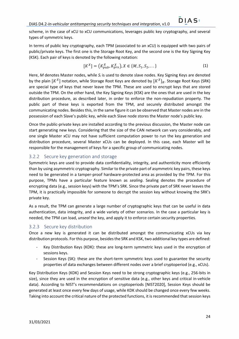
Formal analysis
While intuitively the above-mentioned protocols guarantee a wide range of security properties,
including the secrecy of K (and k), integrity, freshness, non-repudiation, it is good practice to formally
verify a newly designed security protocol using an automated tool. For this purpose, the Scyther
[Cremers2008] tool was used. Scyther is a model checking tool designed under the perfect encryption
assumption, which means that an adversary can only learn an encrypted value if he/she knows the
decryption key. Scyther has been widely used for the analysis of complex real-world security protocols
[Cremers2016] and it already includes a pre-defined adversary based on the Dolev-Yao model
[Dolev2006]. In Scyther, the adversary is assumed to have full control over the underlying
communication network. It can eavesdrop messages, it can replay, split, and concatenate messages.
The formal model, and its verification are listed in Annex A.
Lastly, Figure 5 summarizes the use of the key distribution protocols described in this section.
Figure 5: Summary of xCU to xCU key distribution protocols.
3.3 Key management for xCUs from different suppliers
Nowadays the xCUs in a vehicle are likely to be produced by different suppliers. Therefore, the key
management, i.e., how to exchange the cryptography keys between the xCUs and how to distribute
the pre-shared random numbers required by the cryptography system to the xCUs, is challenging. A
key management based on the peer-to-peer model to solve this problem is proposed in this section.
Next, we first introduce the Diffie-Hellman key exchange, especially the Elliptic Curve Diffie-Hellman
key exchange, which can be applied for the unsecured communication between xCUs. Then, the
distribution of the pre-shared random numbers, which are required by the proposed key exchange
DIAS D4.2-In-vehicular antitampering security techniques and integration, v1.0
27 31/03/2021
mechanism, is presented considering two stages of an xCU’s life cycle, during production and in the
workshop. Moreover, the authentication of the flashing tool is also concerned and an approach of
JSON Web Token is proposed.
3.3.1 Diffie-Hellman and Elliptic Curve Diffie-Hellman key exchange
Diffie-Hellman (DH) key exchange
The Diffie-Hellman key exchange uses the multiplicative group of integers modulo 𝑝, where 𝑝 is a
prime. The mathematic principle is briefly introduced below.
Two parties in the communication, Alice and Bob, wish to agree on a common secret key. First, they
agree on a large prime number 𝑝 and an integer 𝑔 with 2 ≤ 𝑔 ≤ 𝑝 − 2 such that the order of 𝑔 𝑚𝑜𝑑 𝑝
is sufficiently high. The prime 𝑝 and the primitive root 𝑔 can be publicly known. Hence, Bob and Alice
can use their insecure communication channel for this agreement. Now Alice chooses an integer 𝑎 ∈
{0,1, … , 𝑝 − 2} randomly. She computes:
𝐴 = 𝑔𝑎 mod 𝑝 (8)
and sends the result 𝐴 to Bob, but she keeps the exponent 𝑎 secret. Bob chooses an integer 𝑏 ∈
{0,1, … , 𝑝 − 2} randomly. He computes:
𝐵 = 𝑔𝑏 mod 𝑝 (9)
and sends the result 𝐵 to Alice. He also keeps his exponent 𝑏 secret. To obtain the common secret
key, Alice computes:
𝐵𝑎 mod 𝑝 = 𝑔𝑎𝑏 mod 𝑝 (10)
and Bob computes:
𝐴𝑏 mod 𝑝 = 𝑔𝑎𝑏 mod 𝑝 (11)
Then the common key is:
𝐾 = 𝑔𝑎𝑏 mod 𝑝 (12)
We apply the above algorithm [Buchmann2013] in a CAN communication scheme between an Engine
Control Unit (ECU) and a Sensor Control Unit (SCU) as shown in Figure 6.
There are multiple random numbers used during the key exchange. For convenience, the random
numbers are noted with numbers in Figure 6. The ECU and the SCU firstly agree on some common
pre-shared random numbers (1. Public base, modulo) which are the public base and modulo for the
DH key exchange. Then, for each side of the ECU and SCU, private numbers (2. ECU private number
and 3. SCU private number) are generated randomly and used to calculate the associated public
numbers (4. ECU public number and 5. SCU public number). Next, the ECU public number and the SCU
public numbers are sent to each other over CAN, which does not need to be secured. Finally, using the
received SCU public number (5. SCU public number) and the ECU own private number (2. ECU private
number), the ECU can calculate a secret key. In the same time, the SCU also calculates a secret key
using the same method. These two secret keys in the ECU and SCU have the property of being common
and secret (they are numbered as 6. Common secret key), and thus could be used for encrypting and
decrypting messages between the ECU and the SCU. In Table 1 the public and private numbers are
listed, and the corresponding calculation, notation, and the security are summarized.

DIAS D4.2-In-vehicular antitampering security techniques and integration, v1.0
28 31/03/2021
Figure 6: Diffie-Hellman key exchange between an ECU and a SCU.
Table 1: Diffie-Hellman key exchange parameters.
Random numbers Generation/Calculation Notation in the algorithm Security
1. Public base, modulo Pre-shared random numbers 𝑝, 𝑔 Non-secret
2. ECU private number Dynamically generated random number
𝑎 Secret
3. SCU private number Dynamically generated random number
𝑏 Secret
4. ECU public number Calculated using 1 and 2 𝐴 = 𝑔𝑎 𝑚𝑜𝑑 𝑝 Non-secret
5. SCU public number Calculated using 1 and 3 𝐵 = 𝑔𝑏 𝑚𝑜𝑑 𝑝 Non-secret
6. Common secret key (SCU side)
Calculated using 1, 3 and 4 𝐾 = 𝐴𝑏 𝑚𝑜𝑑 𝑝 Secret
6. Common secrete key (ECU side)
Calculated using 1, 2 and 5 𝐾 = 𝐵𝑎 𝑚𝑜𝑑 𝑝 Secret
We use the greatest advantage of the Diffie-Hellman key exchange in which the communication
between two parties does not need to be secured. However, one disadvantage of public-key
cryptography is that the key sizes are typically much larger than those required for symmetric-key
encryption. In Table 2 a comparison of the key sizes is given. The listed Symmetric-Key algorithms are:
Two-key Triple Data Encryption Algorithm (2TDEA), Three-key Triple Data Encryption Algorithm
(3TDEA), Advanced Encryption Standard (AES) 128.
DIAS D4.2-In-vehicular antitampering security techniques and integration, v1.0
29 31/03/2021
Table 2: Comparison of key sizes.
Security strength (bits)
Symmetric-key algorithms
Diffie-Hellman (bits) Elliptic Curve Diffie-
Hellman (bits)
80 2TDEA 1024 160
112 3TDEA 2048 224
128 AES128 3072 256
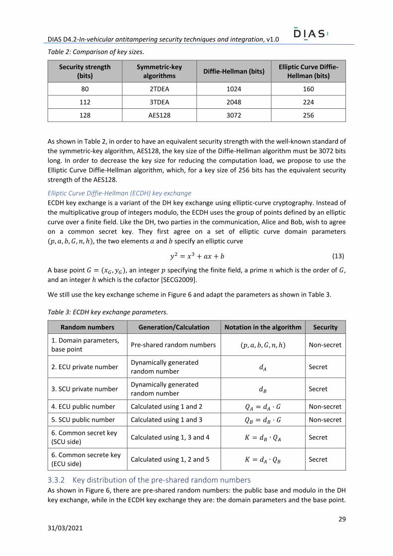
As shown in Table 2, in order to have an equivalent security strength with the well-known standard of
the symmetric-key algorithm, AES128, the key size of the Diffie-Hellman algorithm must be 3072 bits
long. In order to decrease the key size for reducing the computation load, we propose to use the
Elliptic Curve Diffie-Hellman algorithm, which, for a key size of 256 bits has the equivalent security
strength of the AES128.
Elliptic Curve Diffie-Hellman (ECDH) key exchange
ECDH key exchange is a variant of the DH key exchange using elliptic-curve cryptography. Instead of
the multiplicative group of integers modulo, the ECDH uses the group of points defined by an elliptic
curve over a finite field. Like the DH, two parties in the communication, Alice and Bob, wish to agree
on a common secret key. They first agree on a set of elliptic curve domain parameters
(𝑝, 𝑎, 𝑏, 𝐺, 𝑛, ℎ), the two elements 𝑎 and 𝑏 specify an elliptic curve
𝑦2 = 𝑥3 + 𝑎𝑥 + 𝑏 (13)
A base point 𝐺 = (𝑥𝐺 , 𝑦𝐺), an integer 𝑝 specifying the finite field, a prime 𝑛 which is the order of 𝐺,
and an integer ℎ which is the cofactor [SECG2009].
We still use the key exchange scheme in Figure 6 and adapt the parameters as shown in Table 3.
Table 3: ECDH key exchange parameters.
Random numbers Generation/Calculation Notation in the algorithm Security
1. Domain parameters, base point
Pre-shared random numbers (𝑝, 𝑎, 𝑏, 𝐺, 𝑛, ℎ) Non-secret
2. ECU private number Dynamically generated random number
𝑑𝐴 Secret
3. SCU private number Dynamically generated random number
𝑑𝐵 Secret
4. ECU public number Calculated using 1 and 2 𝑄𝐴 = 𝑑𝐴 · 𝐺 Non-secret
5. SCU public number Calculated using 1 and 3 𝑄𝐵 = 𝑑𝐵 · 𝐺 Non-secret
6. Common secret key (SCU side)
Calculated using 1, 3 and 4 𝐾 = 𝑑𝐵 ∙ 𝑄𝐴 Secret
6. Common secrete key (ECU side)
Calculated using 1, 2 and 5 𝐾 = 𝑑𝐴 ∙ 𝑄𝐵 Secret
3.3.2 Key distribution of the pre-shared random numbers As shown in Figure 6, there are pre-shared random numbers: the public base and modulo in the DH
key exchange, while in the ECDH key exchange they are: the domain parameters and the base point.
DIAS D4.2-In-vehicular antitampering security techniques and integration, v1.0
30 31/03/2021
These random numbers need to be distributed in a secure manner and need to be shared with
different parties. In the secure vehicle communication scheme, the random numbers need to be
distributed between ECU and other xCUs (such as SCU), which most probably are from different
suppliers. In this section we consider two stages in the xCU life cycle of the key distribution: 1. during
production [Bißmeyer2016]; 2. in workshop.
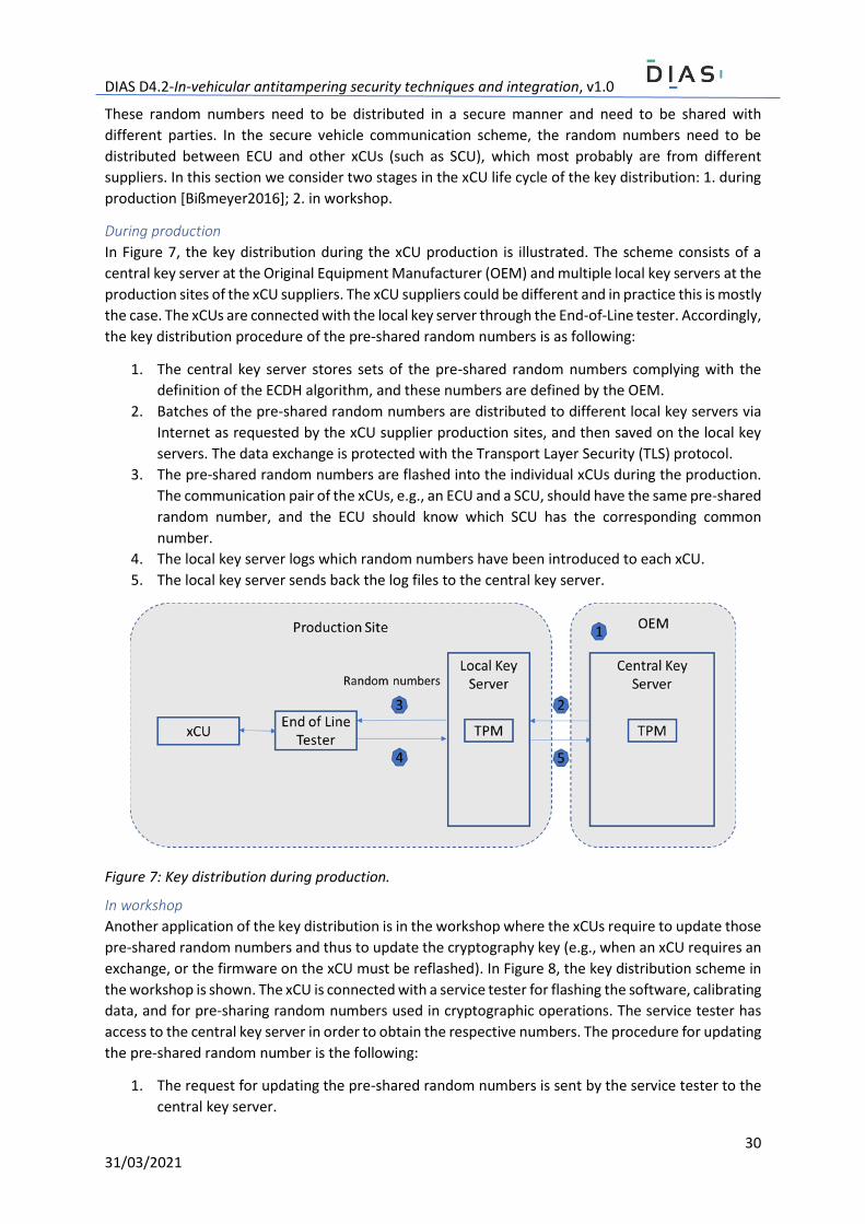
During production
In Figure 7, the key distribution during the xCU production is illustrated. The scheme consists of a
central key server at the Original Equipment Manufacturer (OEM) and multiple local key servers at the
production sites of the xCU suppliers. The xCU suppliers could be different and in practice this is mostly
the case. The xCUs are connected with the local key server through the End-of-Line tester. Accordingly,
the key distribution procedure of the pre-shared random numbers is as following:
1. The central key server stores sets of the pre-shared random numbers complying with the
definition of the ECDH algorithm, and these numbers are defined by the OEM.
2. Batches of the pre-shared random numbers are distributed to different local key servers via
Internet as requested by the xCU supplier production sites, and then saved on the local key
servers. The data exchange is protected with the Transport Layer Security (TLS) protocol.
3. The pre-shared random numbers are flashed into the individual xCUs during the production.
The communication pair of the xCUs, e.g., an ECU and a SCU, should have the same pre-shared
random number, and the ECU should know which SCU has the corresponding common
number.
4. The local key server logs which random numbers have been introduced to each xCU.
5. The local key server sends back the log files to the central key server.
Figure 7: Key distribution during production.
In workshop
Another application of the key distribution is in the workshop where the xCUs require to update those
pre-shared random numbers and thus to update the cryptography key (e.g., when an xCU requires an
exchange, or the firmware on the xCU must be reflashed). In Figure 8, the key distribution scheme in
the workshop is shown. The xCU is connected with a service tester for flashing the software, calibrating
data, and for pre-sharing random numbers used in cryptographic operations. The service tester has
access to the central key server in order to obtain the respective numbers. The procedure for updating
the pre-shared random number is the following:
1. The request for updating the pre-shared random numbers is sent by the service tester to the
central key server.
DIAS D4.2-In-vehicular antitampering security techniques and integration, v1.0
31 31/03/2021
2. The central key server will prove the xCU identity and verify with the respective log files saved
on the server.
3. The central key server will send the required new numbers to the xCU when the verification
is successful.
Figure 8: Key distribution in workshop.
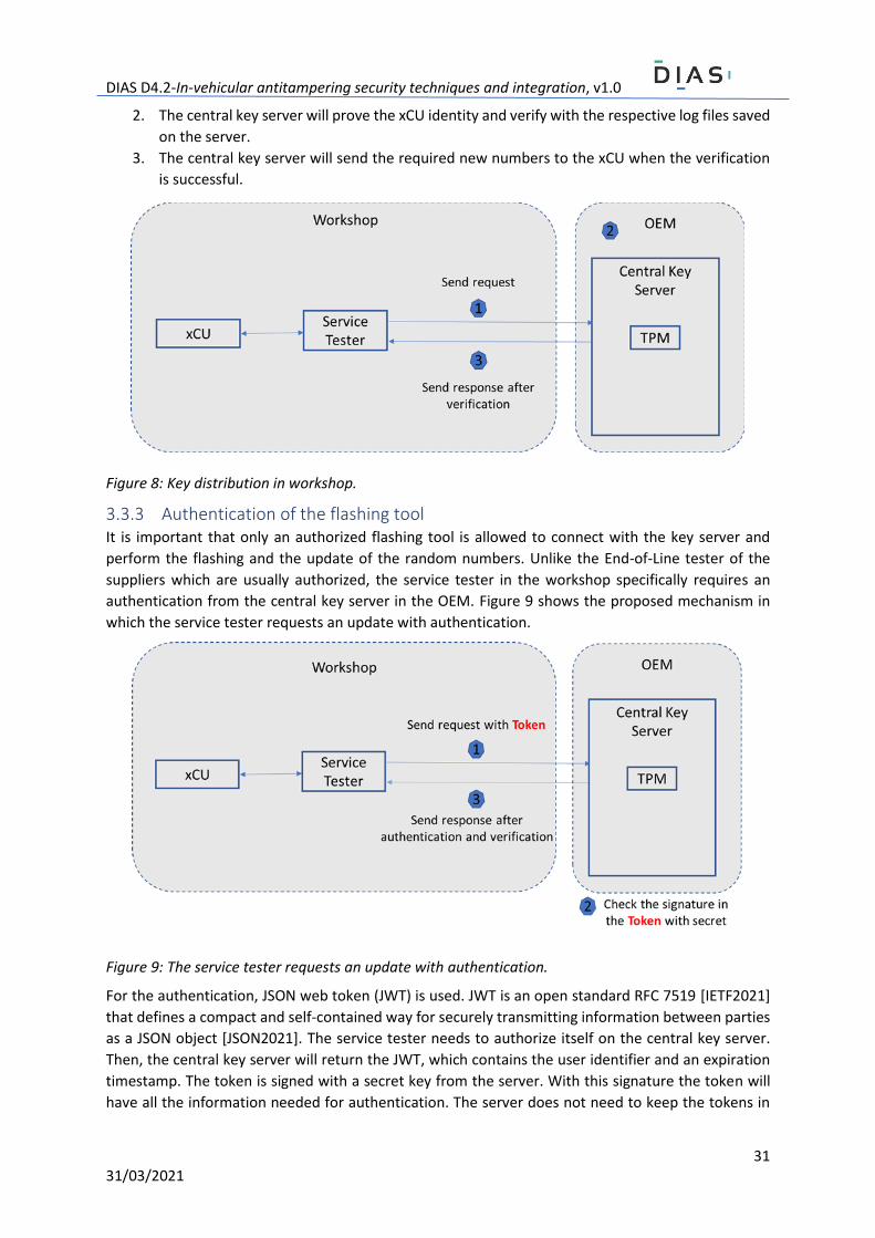
3.3.3 Authentication of the flashing tool It is important that only an authorized flashing tool is allowed to connect with the key server and
perform the flashing and the update of the random numbers. Unlike the End-of-Line tester of the
suppliers which are usually authorized, the service tester in the workshop specifically requires an
authentication from the central key server in the OEM. Figure 9 shows the proposed mechanism in
which the service tester requests an update with authentication.
Figure 9: The service tester requests an update with authentication.
For the authentication, JSON web token (JWT) is used. JWT is an open standard RFC 7519 [IETF2021]
that defines a compact and self-contained way for securely transmitting information between parties
as a JSON object [JSON2021]. The service tester needs to authorize itself on the central key server.
Then, the central key server will return the JWT, which contains the user identifier and an expiration
timestamp. The token is signed with a secret key from the server. With this signature the token will
have all the information needed for authentication. The server does not need to keep the tokens in
DIAS D4.2-In-vehicular antitampering security techniques and integration, v1.0
32 31/03/2021
memory. Therefore, the server can be completely stateless. Considering this property, an
authorization protocol OAuth 2.0 [OAuth2021] can be applied, where an authorization server is used
to issue the JWT and the central key server will verify the token.
After the JWT is issued, the service tester will send requests for updating the random number. Figure
9 shows the proposed mechanism.
1. Suppose the service tester has a valid token. Then it sends the request to the central key
server for updating the random numbers with JWT.
2. The central key server verifies the signature stored in the JWT with the secret key saved on
the server.
3. If the authentication is successful, the central key server sends a response with new random
numbers to the service tester.
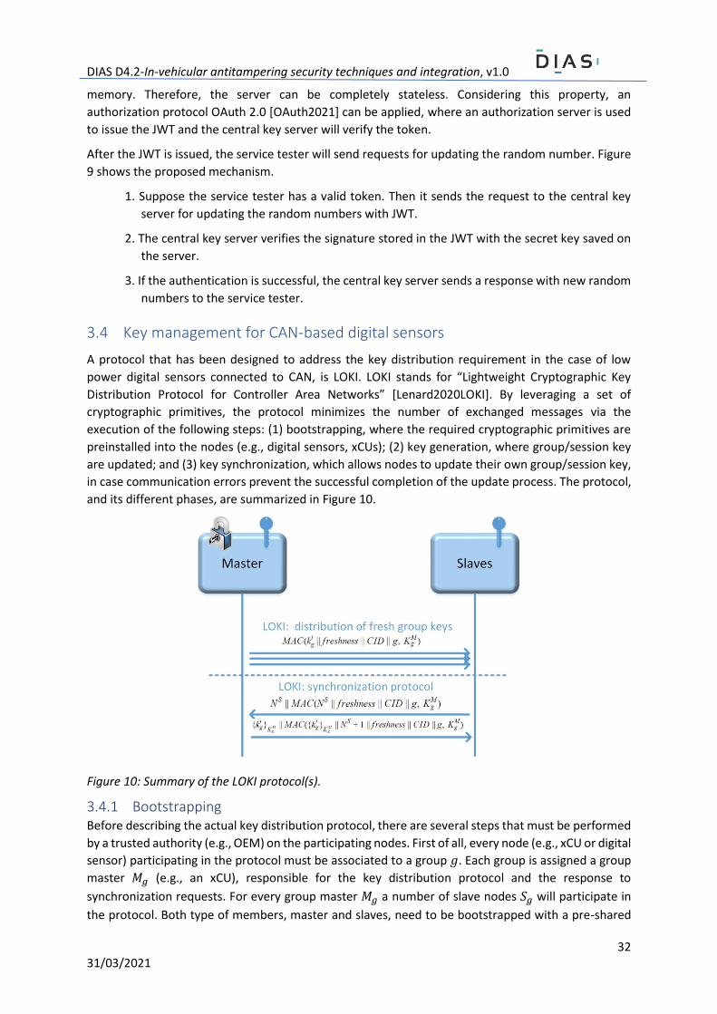
3.4 Key management for CAN-based digital sensors
A protocol that has been designed to address the key distribution requirement in the case of low
power digital sensors connected to CAN, is LOKI. LOKI stands for “Lightweight Cryptographic Key
Distribution Protocol for Controller Area Networks” [Lenard2020LOKI]. By leveraging a set of
cryptographic primitives, the protocol minimizes the number of exchanged messages via the
execution of the following steps: (1) bootstrapping, where the required cryptographic primitives are
preinstalled into the nodes (e.g., digital sensors, xCUs); (2) key generation, where group/session key
are updated; and (3) key synchronization, which allows nodes to update their own group/session key,
in case communication errors prevent the successful completion of the update process. The protocol,
and its different phases, are summarized in Figure 10.
Figure 10: Summary of the LOKI protocol(s).
3.4.1 Bootstrapping Before describing the actual key distribution protocol, there are several steps that must be performed
by a trusted authority (e.g., OEM) on the participating nodes. First of all, every node (e.g., xCU or digital
sensor) participating in the protocol must be associated to a group 𝑔. Each group is assigned a group
master 𝑀𝑔 (e.g., an xCU), responsible for the key distribution protocol and the response to
synchronization requests. For every group master 𝑀𝑔 a number of slave nodes 𝑆𝑔 will participate in
the protocol. Both type of members, master and slaves, need to be bootstrapped with a pre-shared
DIAS D4.2-In-vehicular antitampering security techniques and integration, v1.0
33 31/03/2021
master key 𝐾𝑔𝑀, where 𝑔 is the group identifier and 𝑀 denotes the master of the specific group. The
master key represents a long term cryptographic symmetric key, installed during factory setup by the
trusted authority (i.e., the manufacturer). Using a secret seed 𝑠𝑔𝑀, the first group key 𝑘𝑔
𝑖 , where 𝑖
represents the session index or how many times the key was derived, must be precomputed. The first
group key is used by both master and slaves in order to derive group/session keys. Each node requires
support for a standardised key derivation function (KDF) used in the derivation process of key 𝑘𝑔𝑖 . Last
but not least, the trusted authority must configure the cycle time and the possible vehicle states where
the key generation process can take place. For example, the idle state of the vehicle would be more
suitable for this process than the driving state, when the critical communication processes usually
happen.
3.4.2 Generating fresh group keys The process of generating new group/session keys, denoted as group keys, is a process initiated by
the group master 𝑀𝑔. It consists of a single broadcast message transmitted to every group member:
𝑀𝑔 → 𝑆𝑔: 𝑀𝐴𝐶(𝑘𝑔 𝑖 || 𝑓𝑟𝑒𝑠ℎ𝑛𝑒𝑠𝑠 || 𝐶𝐼𝐷 || 𝑔, 𝐾𝑔
𝑀), (14)
where 𝑀𝐴𝐶(𝑥) denotes a Message Authentication Code computed over a given payload 𝑥, and || is
the concatenation operator applied on two values. The payload over which the MAC tag is computed
consists of the current group key 𝑘𝑔 𝑖 , a 𝑓𝑟𝑒𝑠ℎ𝑛𝑒𝑠𝑠 value (e.g., a counter), the frame identifier 𝐶𝐼𝐷,
and the group identifier 𝑔, by leveraging the preshared master key 𝐾𝑔𝑀. Upon receiving the tag, since
all group members know in advance all the payload primitives, they can verify the authenticity of the
tag and continue with the fresh key generation process.
In order to generate a new group key, after receiving and verifying the tag, a KDF is applied accordingly
on the previous group key 𝑘𝑔 𝑖 , obtaining a new key 𝑘𝑔
𝑖+1, as can be seen in the equation below. Since
the MAC tag size can be over 64 bit long, by following the AUTOSAR SecOC recommendations, the tag
is truncated to 64 bits, thus fitting in a single CAN frame.
𝑘𝑔𝑖+1 = 𝐾𝐷𝐹(𝑘𝑔
𝑖 ). (15)
3.4.3 Synchronization protocol Since the key distribution protocol uses only one message to initiate the generation process of the
new group key 𝑘𝑔 𝑖 , in certain corner cases, due to lost messages, or errors on the communication bus,
a slave 𝑆𝑔 may miss this specific frame. If 𝑆𝑔 misses a generation session, it’s group key 𝑘𝑔 𝑖 becomes
unusable. Consequently, the following synchronization protocol has been developed:
𝐶ℎ𝑎𝑙𝑙𝑒𝑛𝑔𝑒 𝑆𝑔 → 𝑀𝑔: 𝑁𝑆 || 𝑀𝐴𝐶(𝑁𝑆 || 𝑓𝑟𝑒𝑠ℎ𝑛𝑒𝑠𝑠 || 𝐶𝐼𝐷 || 𝑔, 𝐾𝑔𝑀) (16)
𝑅𝑒𝑠𝑝𝑜𝑛𝑠𝑒 𝑀𝑔 → 𝑆𝑔: {𝑘𝑔𝑖 }𝐾𝑔
𝑀 || 𝑀𝐴𝐶({𝑘𝑔𝑖 }𝐾𝑔
𝑀 || 𝑁𝑆 + 1 || 𝑓𝑟𝑒𝑠ℎ𝑛𝑒𝑠𝑠 || 𝐶𝐼𝐷 || 𝑔, 𝐾𝑔𝑀). (17)
The synchronization protocol follows a challenge-response communication pattern, where a slave 𝑆𝑔
requests the current group key from the master 𝑀𝑔. The slave 𝑆𝑔 sends a challenge under the form of
a nonce 𝑁𝑆 together with a MAC tag computed over the nonce 𝑁𝑆, concatenated with a
𝑓𝑟𝑒𝑠ℎ𝑛𝑒𝑠𝑠 value, the frame identifier 𝐶𝐼𝐷, and the group identifier 𝑔, using the master key 𝐾𝑔𝑀. To
reduce the number of sent messages, the length of 𝑁𝑆 can be set to 64 bits, and, similarly, the MAC
tag can be truncated to 64 bits. This way, each of the two messages can be transmitted in one single
CAN frame.
To respond to the challenge, 𝑀𝑔 first needs to verify the authenticity of the MAC tag. If the verification
is successful, it responds with the current group key 𝑘𝑔 𝑖 , encrypted using the preshared master key
DIAS D4.2-In-vehicular antitampering security techniques and integration, v1.0
34 31/03/2021
𝐾𝑔𝑀. For this purpose, a MAC tag is computed to ensure the authenticity and integrity of the message.
The tag is computed over the encrypted group key {𝑘𝑔 𝑖 }𝐾𝑔
𝑀, concatenated with the received challenge
nonce incremented by 1 (𝑁𝑆 + 1), a 𝑓𝑟𝑒𝑠ℎ𝑛𝑒𝑠𝑠 value, the frame identifier 𝐶𝐼𝐷, and the group
identifier 𝑔, by leveraging the master key 𝐾𝑔𝑀.
The number of frames required to be sent by 𝑀𝑔 in the response structure depends on several
parameters, such as the length of the group key, the encryption algorithm used to encrypt the group
key, and the value of the MAC tag (truncated or not).
LOKI’s formal model and analysis with the Scyther tool are listed in Annex A.
4 Secure data exchange By leveraging the techniques described in the previous section, session keys are securely distributed
amongst communicating participants. Once this process is completed, data can be securely
exchanged. While other security properties may be also explored in the future, at the time of writing
of this document, the authenticity and integrity (via authenticity), as well as freshness of data transfers
are considered to be the most relevant and generally required. This is also in accordance with
AUTOSAR SecOC’s recommendations. The remainder of this section describes the different protocols
that have been explored so far within the DIAS project. However, it should be noted that the
documented techniques may significantly change and other variants may also be explored according
to the results of the integration analysis and tests.
4.1 Secure CAN and SecOC Light
The CAN protocol is a common protocol used for communication between the nodes found in a
vehicle’s network (e.g., sensors in the exhaust pipe for the aftertreatment system communication with
the engine control unit). Nodes are communicating by following a multi-master principle. Accordingly,
each frame sent by an xCU has a unique CID, which needs to be defined only once for a particular
network. To access the CAN bus, every sender monitors the bus and stops sending its own frame when
it detects that a different node is already sending a frame with a lower CID. Therefore, the message
with the lower CID has the higher priority.
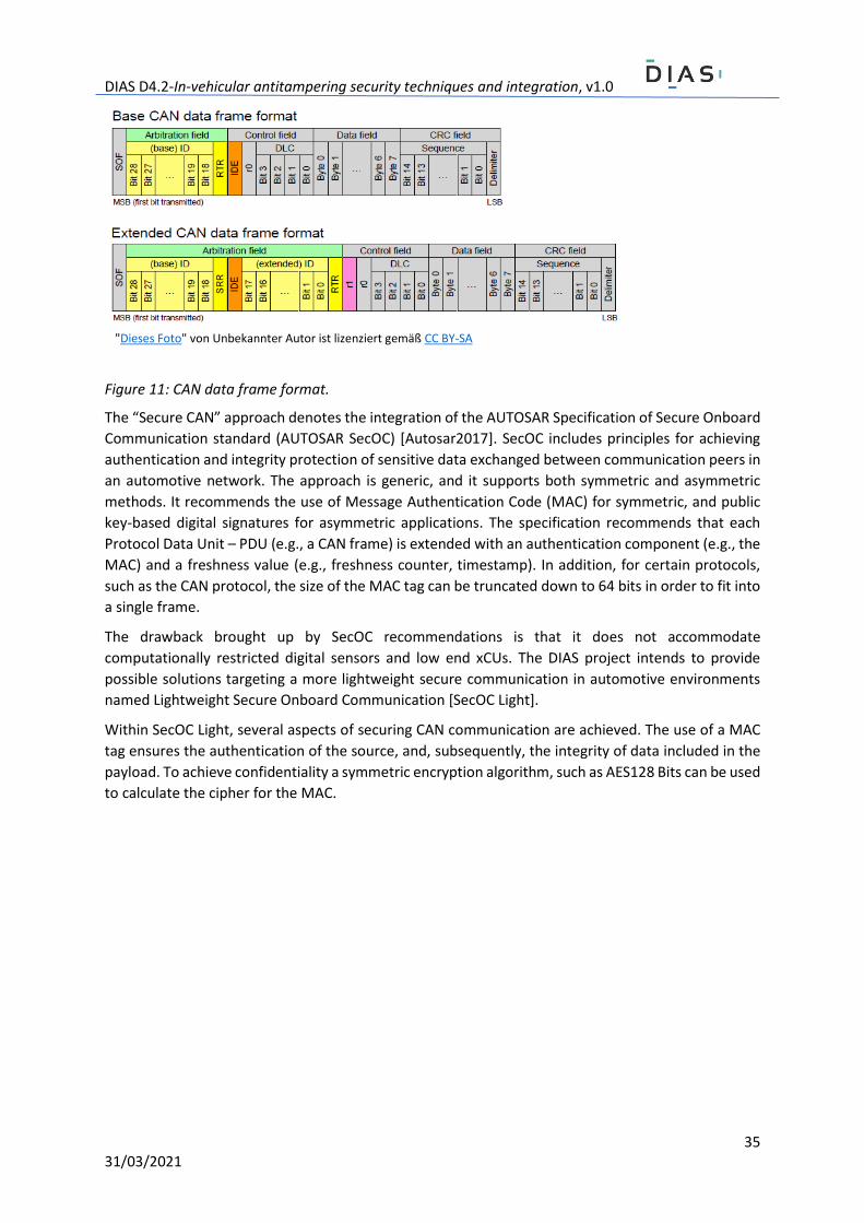
As shown in Figure 11 the CAN protocol defines frames with the Standard and Extended CIDs.
Extended identifiers are used most likely found in commercial vehicles. Each frame has a payload of
up to 64 bits. The payload is used by xCUs to periodically transfer data such as: physical signals,
temperature signal, diagnosis results etc., to the ECU.
DIAS D4.2-In-vehicular antitampering security techniques and integration, v1.0
35 31/03/2021
Figure 11: CAN data frame format.
The “Secure CAN” approach denotes the integration of the AUTOSAR Specification of Secure Onboard
Communication standard (AUTOSAR SecOC) [Autosar2017]. SecOC includes principles for achieving
authentication and integrity protection of sensitive data exchanged between communication peers in
an automotive network. The approach is generic, and it supports both symmetric and asymmetric
methods. It recommends the use of Message Authentication Code (MAC) for symmetric, and public
key-based digital signatures for asymmetric applications. The specification recommends that each
Protocol Data Unit – PDU (e.g., a CAN frame) is extended with an authentication component (e.g., the
MAC) and a freshness value (e.g., freshness counter, timestamp). In addition, for certain protocols,
such as the CAN protocol, the size of the MAC tag can be truncated down to 64 bits in order to fit into
a single frame.
The drawback brought up by SecOC recommendations is that it does not accommodate
computationally restricted digital sensors and low end xCUs. The DIAS project intends to provide
possible solutions targeting a more lightweight secure communication in automotive environments
named Lightweight Secure Onboard Communication [SecOC Light].
Within SecOC Light, several aspects of securing CAN communication are achieved. The use of a MAC
tag ensures the authentication of the source, and, subsequently, the integrity of data included in the
payload. To achieve confidentiality a symmetric encryption algorithm, such as AES128 Bits can be used
to calculate the cipher for the MAC.
"Dieses Foto" von Unbekannter Autor ist lizenziert gemäß CC BY-SA
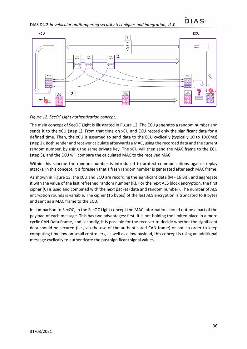
DIAS D4.2-In-vehicular antitampering security techniques and integration, v1.0
36 31/03/2021
Figure 12: SecOC Light authentication concept.
The main concept of SecOC Light is illustrated in Figure 12. The ECU generates a random number and
sends it to the xCU (step 1). From that time on xCU and ECU record only the significant data for a
defined time. Then, the xCU is assumed to send data to the ECU cyclically (typically 10 to 1000ms)
(step 2). Both sender and receiver calculate afterwards a MAC, using the recorded data and the current
random number, by using the same private key. The xCU will then send the MAC frame to the ECU
(step 3), and the ECU will compare the calculated MAC to the received MAC.
Within this scheme the random number is introduced to protect communications against replay attacks. In this concept, it is foreseen that a fresh random number is generated after each MAC frame.
As shown in Figure 13, the xCU and ECU are recording the significant data (M - 16 Bit), and aggregate
it with the value of the last refreshed random number (R). For the next AES block encryption, the first
cipher (C) is used and combined with the next packet (data and random number). The number of AES
encryption rounds is variable. The cipher (16 bytes) of the last AES encryption is truncated to 8 bytes
and sent as a MAC frame to the ECU.
In comparison to SecOC, in the SecOC Light concept the MAC information should not be a part of the
payload of each message. This has two advantages: first, it is not holding the limited place in a more
cyclic CAN Data Frame, and secondly, it is possible for the receiver to decide whether the significant
data should be secured (i.e., via the use of the authenticated CAN frame) or not. In order to keep
computing time low on small controllers, as well as a low busload, this concept is using an additional
message cyclically to authenticate the past significant signal values.
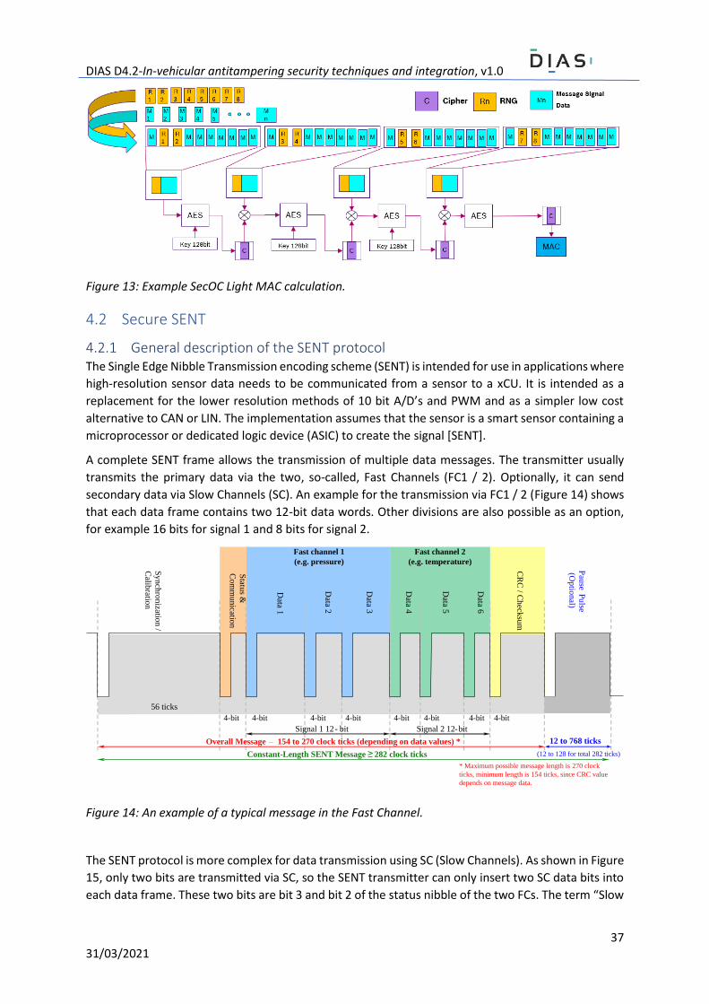
DIAS D4.2-In-vehicular antitampering security techniques and integration, v1.0
37 31/03/2021
Figure 13: Example SecOC Light MAC calculation.
4.2 Secure SENT
4.2.1 General description of the SENT protocol The Single Edge Nibble Transmission encoding scheme (SENT) is intended for use in applications where
high-resolution sensor data needs to be communicated from a sensor to a xCU. It is intended as a
replacement for the lower resolution methods of 10 bit A/D’s and PWM and as a simpler low cost
alternative to CAN or LIN. The implementation assumes that the sensor is a smart sensor containing a
microprocessor or dedicated logic device (ASIC) to create the signal [SENT].
A complete SENT frame allows the transmission of multiple data messages. The transmitter usually
transmits the primary data via the two, so-called, Fast Channels (FC1 / 2). Optionally, it can send
secondary data via Slow Channels (SC). An example for the transmission via FC1 / 2 (Figure 14) shows
that each data frame contains two 12-bit data words. Other divisions are also possible as an option,
for example 16 bits for signal 1 and 8 bits for signal 2.
Figure 14: An example of a typical message in the Fast Channel.
The SENT protocol is more complex for data transmission using SC (Slow Channels). As shown in Figure
15, only two bits are transmitted via SC, so the SENT transmitter can only insert two SC data bits into
each data frame. These two bits are bit 3 and bit 2 of the status nibble of the two FCs. The term “Slow
56 ticks
Syn
chro
nizatio
n /
Calib
ration
Statu
s &
Co
mm
un
ication
Data 1
Data 2
Data 3
Data 4
Data 5
Data 6
CR
C / C
heck
sum
Signal 1 12 - bit Signal 2 12-bit
Overall Message – 154 to 270 clock ticks (depending on data values) *
Pau
se P
ulse
(Optio
nal)
12 to 768 ticks
Constant-Length SENT Message 282 clock ticks
4-bit4-bit 4-bit 4-bit 4-bit 4-bit 4-bit 4-bit
Fast channel 1
(e.g. pressure)
Fast channel 2
(e.g. temperature)
* Maximum possible message length is 270 clock
ticks, minimum length is 154 ticks, since CRC value
depends on message data.
(12 to 128 for total 282 ticks)

DIAS D4.2-In-vehicular antitampering security techniques and integration, v1.0
38 31/03/2021
Channels” comes from the fact that it takes many FC data frames to transfer a value completely via
SC. For example, 18 FC data frames are required to transmit 12 SC data bits. The actual performance
of this function is that up to 32 different data can be used in each serial message cycle, without any
impact on the primary sensor data, which is sent via the two FCs.
Figure 15: An example of a typical message in the Slow Channel.
With these SCs, for example, temperature measurement values, diagnostic data and production codes
can be continuously monitored (i.e., data that usually do not change or change at a significantly slower
rate than the primary sensor data). Each of the maximum of 32 SCs receives an ID that is transferred
with the data. The list of message IDs is usually unique for each product and is often defined in the
product data sheet or in application notes.
4.2.2 The Secure SENT protocol There are three aspects of secure SENT communication (patent No. DE102020208806A1): the
authentication of the source, the integrity of the messages and the secrecy of information by
encrypting the relevant information parts. Integrity and authenticity are achieved using relatively
simple algorithms such as a Cipher-based Message Authentication Code (CMAC), where a secret
symmetrical key that is kept secret is generated for the sender and receiver of a message.
Confidentiality can be achieved using a symmetrical encryption algorithm such as the 128-bit
Advanced Encryption Standard (AES128). In software solutions, a dedicated CMAC or AES128 driver
module is implemented as part of a standard encryption library.
Constant-Length SENT Message 282 clock ticks
4-bit4-bit 4-bit 4-bit 4-bit 4-bit 4-bit 4-bit
Fast channel 1
(e.g. pressure)
Fast channel 2
(e.g. temperature)
Pause pulseCRCSynchronization/calibration pulse
S&C
154 to 270 clock ticks (depending on data values)
Serial Communication
Frame No.
Serial Data (bit #3)
Serial Data (bit #2)
1 2 43 5 6 7 8 9 10 11 12 13 14 15 16 17 18
6-bit CRC
1 1 1 1 1 1 0 C 0 0 0 0 0 0 0 0 0 08-bit ID (3-0)8-bit ID (7-4)
12-bit data field
Serial message data frameSENT frame #18
S&C
[2]
S&C
[3]
S&C
[1]
S&C
[0]
Serial data
message bits
SENT frame #4
SENT frame #3SENT frame #1
SENT frame #1 SENT frame #2 SENT frame #3
SENT data frame
SENT frame length : typ. 0.846 ms max. 1 ms (@ 3µs ticks)
Serial message frame length : typ. 15.2 ms (@ 3µs ticks)

DIAS D4.2-In-vehicular antitampering security techniques and integration, v1.0
39 31/03/2021
Figure 16: SENT Authentication Concept.
As shown in Figure 16, the sender (Sensor) of the SENT messages generates a Message Authentication
Code (MAC) based on FCs sensor data and inserts part of this into the SENT SCs. The receiver of these
messages must have successfully verified the MAC portion before accepting the received data for
further processing. MACs are generated with a secret symmetric key that is shared between the
sender (Sensor) and receiver (ECU) of a message. Only Sensors and the ECUs that know this symmetric
key can generate a valid MAC through the secret symmetric key. The symmetric keys can be imported
directly in containers or in OEM-specific formats (i.e., by using key management techniques such as
the ones described in section “3.2 Key management for xCUs”).
Figure 17 shows an example of the MAC computation: the Sensor collects 2N bit values (1<=N<=6) of
each 12 bits pressure signal (SENT Frame) from one SENT Serial message Cycle (576 SENT Frame). It
creates 9N 128-bit message blocks Mx (M1, M2, …M9N). The CMAC of message blocks Mx will be
calculated based on a secret key and the block cipher AES. A 24-bit MAC Code (TMAC) will be sent to
the ECU through the SENT slow channel of the next Serial message Cycle.
The ECU also collects 2N bits values (1<=N<=6) of each 12 bits of pressure signal from the same Serial
message Cycle and creates 9N 128 bits message blocks Mx (M1, M2, …, M9N). It also calculates the
CMAC of message blocks Mx using the same secret key and the block cipher AES. The ECU then verifies
the calculated MAC Code with the MAC value that it received from the Sensor.
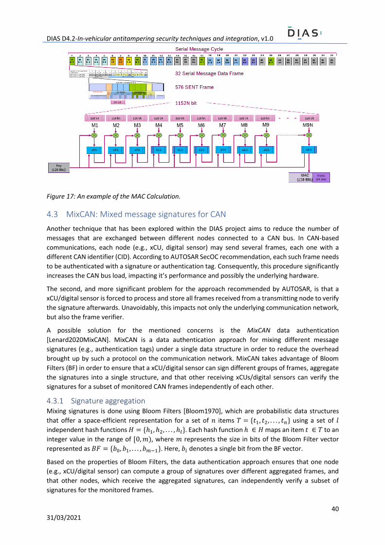
DIAS D4.2-In-vehicular antitampering security techniques and integration, v1.0
40 31/03/2021
Figure 17: An example of the MAC Calculation.
4.3 MixCAN: Mixed message signatures for CAN
Another technique that has been explored within the DIAS project aims to reduce the number of
messages that are exchanged between different nodes connected to a CAN bus. In CAN-based
communications, each node (e.g., xCU, digital sensor) may send several frames, each one with a
different CAN identifier (CID). According to AUTOSAR SecOC recommendation, each such frame needs
to be authenticated with a signature or authentication tag. Consequently, this procedure significantly
increases the CAN bus load, impacting it’s performance and possibly the underlying hardware.
The second, and more significant problem for the approach recommended by AUTOSAR, is that a
xCU/digital sensor is forced to process and store all frames received from a transmitting node to verify
the signature afterwards. Unavoidably, this impacts not only the underlying communication network,
but also the frame verifier.
A possible solution for the mentioned concerns is the MixCAN data authentication
[Lenard2020MixCAN]. MixCAN is a data authentication approach for mixing different message
signatures (e.g., authentication tags) under a single data structure in order to reduce the overhead
brought up by such a protocol on the communication network. MixCAN takes advantage of Bloom
Filters (BF) in order to ensure that a xCU/digital sensor can sign different groups of frames, aggregate
the signatures into a single structure, and that other receiving xCUs/digital sensors can verify the
signatures for a subset of monitored CAN frames independently of each other.
4.3.1 Signature aggregation Mixing signatures is done using Bloom Filters [Bloom1970], which are probabilistic data structures
that offer a space-efficient representation for a set of 𝑛 items 𝑇 = {𝑡1, 𝑡2, . . . , 𝑡𝑛} using a set of 𝑙
independent hash functions 𝐻 = {ℎ1, ℎ2, . . . , ℎ𝑙}. Each hash function ℎ ∈ 𝐻 maps an item 𝑡 ∈ 𝑇 to an
integer value in the range of [0, 𝑚), where 𝑚 represents the size in bits of the Bloom Filter vector
represented as 𝐵𝐹 = {𝑏0, 𝑏1, . . . , 𝑏𝑚−1}. Here, 𝑏𝑖 denotes a single bit from the BF vector.
Based on the properties of Bloom Filters, the data authentication approach ensures that one node
(e.g., xCU/digital sensor) can compute a group of signatures over different aggregated frames, and
that other nodes, which receive the aggregated signatures, can independently verify a subset of
signatures for the monitored frames.
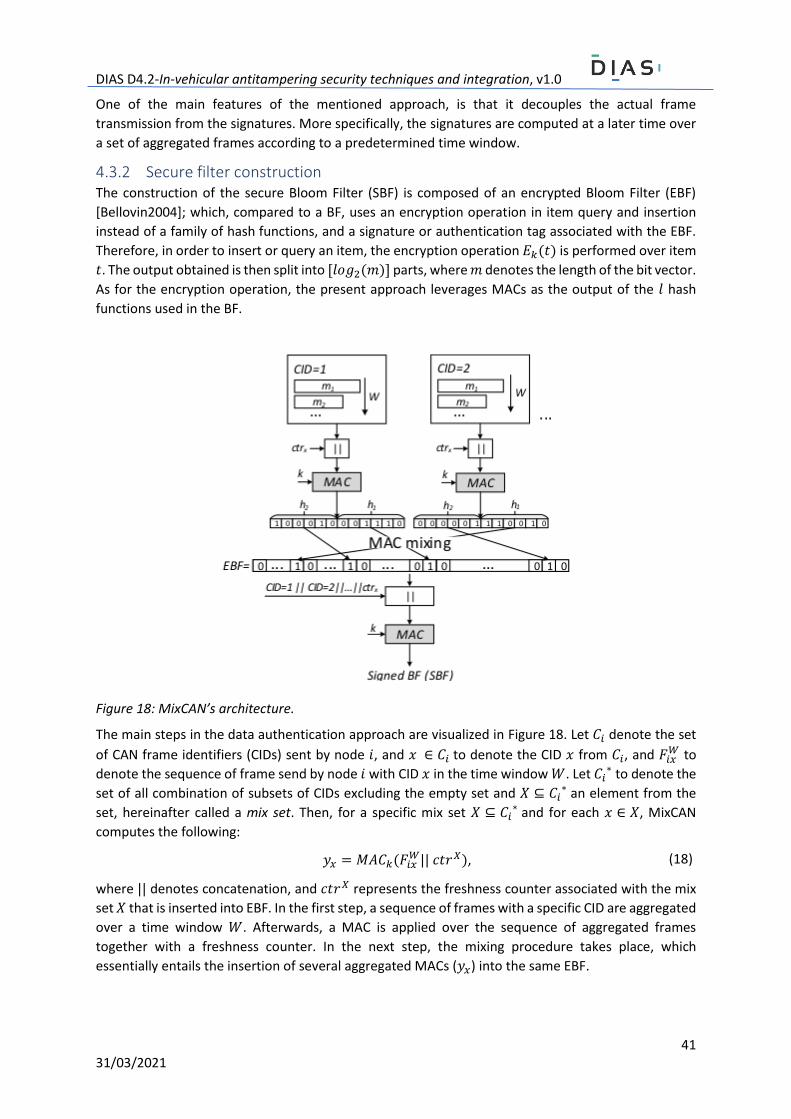
DIAS D4.2-In-vehicular antitampering security techniques and integration, v1.0
41 31/03/2021
One of the main features of the mentioned approach, is that it decouples the actual frame
transmission from the signatures. More specifically, the signatures are computed at a later time over
a set of aggregated frames according to a predetermined time window.
4.3.2 Secure filter construction The construction of the secure Bloom Filter (SBF) is composed of an encrypted Bloom Filter (EBF)
[Bellovin2004]; which, compared to a BF, uses an encryption operation in item query and insertion
instead of a family of hash functions, and a signature or authentication tag associated with the EBF.
Therefore, in order to insert or query an item, the encryption operation 𝐸𝑘(𝑡) is performed over item
𝑡. The output obtained is then split into [𝑙𝑜𝑔2(𝑚)] parts, where 𝑚 denotes the length of the bit vector.
As for the encryption operation, the present approach leverages MACs as the output of the 𝑙 hash
functions used in the BF.
Figure 18: MixCAN’s architecture.
The main steps in the data authentication approach are visualized in Figure 18. Let 𝐶𝑖 denote the set
of CAN frame identifiers (CIDs) sent by node 𝑖, and 𝑥 ∈ 𝐶𝑖 to denote the CID 𝑥 from 𝐶𝑖, and 𝐹𝑖𝑥𝑊 to
denote the sequence of frame send by node 𝑖 with CID 𝑥 in the time window 𝑊. Let 𝐶𝑖∗ to denote the
set of all combination of subsets of CIDs excluding the empty set and 𝑋 ⊆ 𝐶𝑖∗ an element from the
set, hereinafter called a mix set. Then, for a specific mix set 𝑋 ⊆ 𝐶𝑖∗ and for each 𝑥 ∈ 𝑋, MixCAN
computes the following:
𝑦𝑥 = 𝑀𝐴𝐶𝑘(𝐹𝑖𝑥𝑊|| 𝑐𝑡𝑟𝑋), (18)
where || denotes concatenation, and 𝑐𝑡𝑟𝑋 represents the freshness counter associated with the mix
set 𝑋 that is inserted into EBF. In the first step, a sequence of frames with a specific CID are aggregated
over a time window 𝑊. Afterwards, a MAC is applied over the sequence of aggregated frames
together with a freshness counter. In the next step, the mixing procedure takes place, which
essentially entails the insertion of several aggregated MACs (𝑦𝑥) into the same EBF.
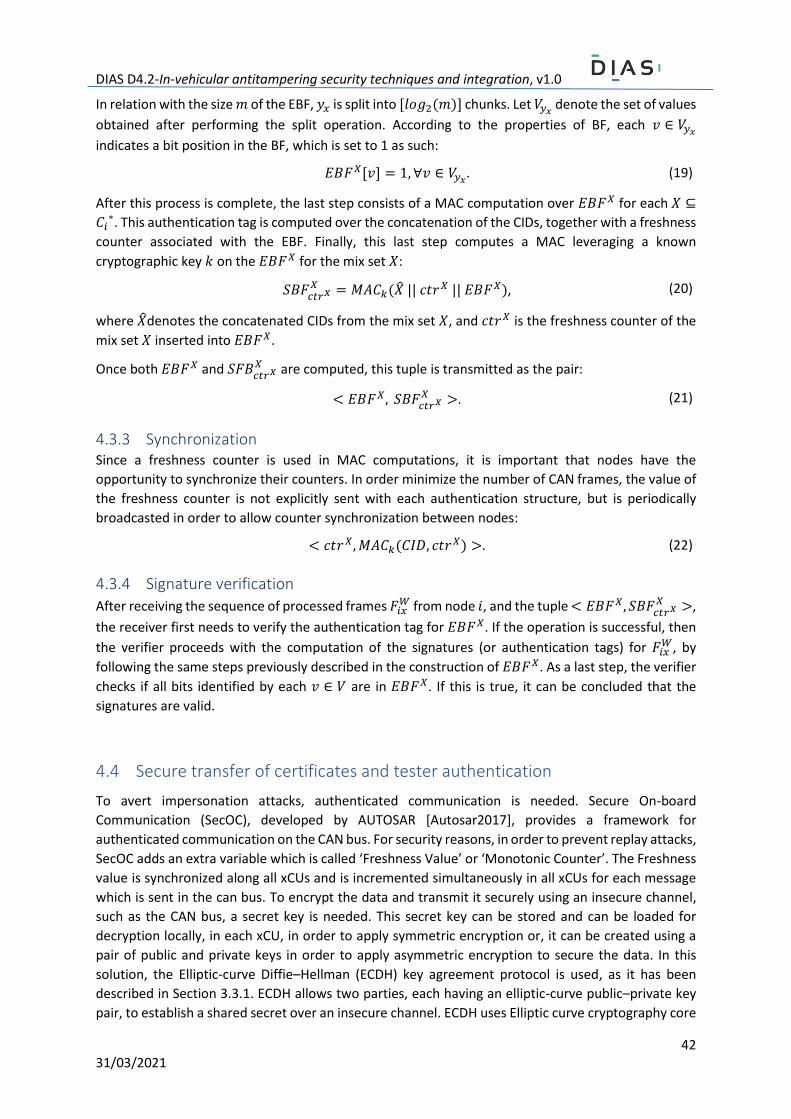
DIAS D4.2-In-vehicular antitampering security techniques and integration, v1.0
42 31/03/2021
In relation with the size 𝑚 of the EBF, 𝑦𝑥 is split into [𝑙𝑜𝑔2(𝑚)] chunks. Let 𝑉𝑦𝑥 denote the set of values
obtained after performing the split operation. According to the properties of BF, each 𝑣 ∈ 𝑉𝑦𝑥
indicates a bit position in the BF, which is set to 1 as such:
𝐸𝐵𝐹𝑋[𝑣] = 1, ∀𝑣 ∈ 𝑉𝑦𝑥. (19)
After this process is complete, the last step consists of a MAC computation over 𝐸𝐵𝐹𝑋 for each 𝑋 ⊆
𝐶𝑖∗. This authentication tag is computed over the concatenation of the CIDs, together with a freshness
counter associated with the EBF. Finally, this last step computes a MAC leveraging a known
cryptographic key 𝑘 on the 𝐸𝐵𝐹𝑋 for the mix set 𝑋:
𝑆𝐵𝐹𝑐𝑡𝑟𝑋𝑋 = 𝑀𝐴𝐶𝑘(�̂� || 𝑐𝑡𝑟𝑋 || 𝐸𝐵𝐹𝑋), (20)
where �̂�denotes the concatenated CIDs from the mix set 𝑋, and 𝑐𝑡𝑟𝑋 is the freshness counter of the
mix set 𝑋 inserted into 𝐸𝐵𝐹𝑋.
Once both 𝐸𝐵𝐹𝑋 and 𝑆𝐹𝐵𝑐𝑡𝑟𝑋𝑋 are computed, this tuple is transmitted as the pair:
< 𝐸𝐵𝐹𝑋, 𝑆𝐵𝐹𝑐𝑡𝑟𝑋𝑋 >. (21)
4.3.3 Synchronization Since a freshness counter is used in MAC computations, it is important that nodes have the
opportunity to synchronize their counters. In order minimize the number of CAN frames, the value of
the freshness counter is not explicitly sent with each authentication structure, but is periodically
broadcasted in order to allow counter synchronization between nodes:
< 𝑐𝑡𝑟𝑋, 𝑀𝐴𝐶𝑘(𝐶𝐼𝐷, 𝑐𝑡𝑟𝑋) >. (22)
4.3.4 Signature verification
After receiving the sequence of processed frames 𝐹𝑖𝑥𝑊 from node 𝑖, and the tuple < 𝐸𝐵𝐹𝑋, 𝑆𝐵𝐹
𝑐𝑡𝑟𝑋𝑋 >,
the receiver first needs to verify the authentication tag for 𝐸𝐵𝐹𝑋. If the operation is successful, then
the verifier proceeds with the computation of the signatures (or authentication tags) for 𝐹𝑖𝑥𝑊, by
following the same steps previously described in the construction of 𝐸𝐵𝐹𝑋. As a last step, the verifier
checks if all bits identified by each 𝑣 ∈ 𝑉 are in 𝐸𝐵𝐹𝑋. If this is true, it can be concluded that the
signatures are valid.
4.4 Secure transfer of certificates and tester authentication
To avert impersonation attacks, authenticated communication is needed. Secure On-board
Communication (SecOC), developed by AUTOSAR [Autosar2017], provides a framework for
authenticated communication on the CAN bus. For security reasons, in order to prevent replay attacks,
SecOC adds an extra variable which is called ‘Freshness Value’ or ‘Monotonic Counter’. The Freshness
value is synchronized along all xCUs and is incremented simultaneously in all xCUs for each message
which is sent in the can bus. To encrypt the data and transmit it securely using an insecure channel,
such as the CAN bus, a secret key is needed. This secret key can be stored and can be loaded for
decryption locally, in each xCU, in order to apply symmetric encryption or, it can be created using a
pair of public and private keys in order to apply asymmetric encryption to secure the data. In this
solution, the Elliptic-curve Diffie–Hellman (ECDH) key agreement protocol is used, as it has been
described in Section 3.3.1. ECDH allows two parties, each having an elliptic-curve public–private key
pair, to establish a shared secret over an insecure channel. ECDH uses Elliptic curve cryptography core
DIAS D4.2-In-vehicular antitampering security techniques and integration, v1.0
43 31/03/2021
principles to work. Elliptic curve cryptography is preferred due to its computational efficiency and
relatively small key length. In the current implementation, the SECP256R1 curve is used and should be
consistent on certificate and key-pair generation.
Within DIAS, an enhanced SecOC solution is used to avoid fake signals from CCU to xCU as well as to
establish a secure communication among different devices by providing data integrity and
authentication. Data authentication is achieved via Message Authentication Code (MAC). In addition,
using Enhanced SecOC, every device that is connected to the CAN bus is able to transfer data only to
the desired devices which, in their turn, are able to decrypt and read the data. This can be done only
if the same derived key has been generated and if the freshness value is synchronized with the
sender’s freshness value. Thus, fake signals or other efforts to deceive the in-vehicle system can be
avoided.
The Enhanced SecOC solution is described in more details in Section 6.
The Service Provider (SP) which can be a vehicle workshop, vehicle technical inspection centres etc.,
uses X.509 certificates for its devices in order to access the vehicle’s xCUs. The X.509 certificates have
a fundamental role in the in-vehicle communication with Enhanced SecOC protocol. This section
describes in detail the process of issuing, verifying and revoking the X.509 certificate for tester devices.
The SP initiates the process for obtaining a X.509 certificate for its tester devices. The SPs mobile
devices, among other components, include a Certificate Authority (CA) client. The CA client handles
all the CA (X.509 certificate)-related necessary actions, such us the creation of the cryptographic keys
and Certificate Signing Requests (CSRs). On the other hand, Registration Authorities (RAs) such as
transportation ministries, customs and national legal entities, in general responsible for issuing legal
papers, operate the CA Server, which is responsible for issuing, verifying and revoking the X.509
Certificates to the vehicles. However, both SPs and RAs have respective applications, which handle the
various interactions between them.
As a first step, the SP generates a pair of keys (public and private) through its CA client. The public and
private key pair constitutes an elliptic curve key pair with curve P-256 and is stored locally. Using these
keys, the SP CA Client creates a CSR. The CSR contains information and special characteristics regarding
the SP and the Tester Device it is going to use. More specifically the CommonName in the Subject Field
of X.509 contains the name of each device. In addition, a custom attribute inside a custom extension
with ASN.1 OID (Abstract Syntax Notation Object Identifier) “1.2.3.4.5.1.2.4.5.6” has been added. This
extension contains the Media Access Control Address (MacAddress) of the SP mobile device in order
to check from in-vehicle security and identify the device uniquely to prevent unauthorized access
while ensuring the data origin. The Enhanced SecOC protocol demands the public key of each entity,
hence, the correlation between the keys and the entities represented through them must be always
trusted and verifiable. Having an X.509 that includes a MacAddress extension, the sender’s
authenticity is extended to a degree. This characteristic adds a level of authenticity in the existing
X.509 and in conjunction with the automated MacAddress verification function in Tester Side, the
binding between the Tester and the Tester public key becomes stronger and secure. In addition, the
MacAddress can also be used in the IDS (intrusion detection system) for the DIAS solution.
In this sense, we can verify that a specific public key belongs to an entity that is valid as well as verified
by a trusted Certificate Authority and can perform the Enhanced SecOC protocol successfully. Thus,
authentication of data transfers and verifiable data integrity using X.509 Certificates and Enhanced
SecOC communication among xCUs and a tester device is achieved. Therefore, the certificate to be
issued will contain the above characteristics.

DIAS D4.2-In-vehicular antitampering security techniques and integration, v1.0
44 31/03/2021
The generated CSR is sent to the RA, which is the software component implementing the solution’s
logic, via a secure communication channel. The RA first verifies the MacAddress of the SP by sending
an automatic request. After verifying the MacAddress, the RA forwards the CSR to RA CA Server, which
is responsible for the certificate issuance. The RA CA Server issues the certificate and sends it back to
the RA, which in turns sends the Certificate to the SP and informs the SP CA Client about the issuance.
The SP stores the received Certificate in its local storage. Thus, when the SP wants to establish a
connection between its tester device and vehicle, is able to retrieve the Certificates and the
corresponding keys from SP mobile local storage. These artefacts are used in order to authenticate
the SP.
RAs are responsible for the revocation of the Certificates that are issued through the CA Server. The
CA Server holds a Certificate Revocation List (CRL) that contains all the untrustworthy certificates,
which have been revoked. When a certificate needs to be revoked before its expiration date, the CA
Server updates the CRL to include the revoked certificate. The certificate that has been added to CLR
is no longer valid and SP must request a new certificate through a CSR.
Finally, the certificate has to be validated. The CCU checks if the certificate is valid and has not expired,
and communicates with the CA Server to check if it has been revoked. If it has not been revoked, then
the tester device can communicate with the xCUs. If it has been revoked, no further communication
is possible and the testers get disconnected. Figure 19 depicts the interactions between the actors.
Figure 19: Tester X.509 Certificate Overall Flow
The CRS and X.509 Certificate content as well as the steps for X.509 Certificate Issuance and
Verification have been included in Annex D.
DIAS D4.2-In-vehicular antitampering security techniques and integration, v1.0
45 31/03/2021
4.5 Secure firmware update, secure boot, and address randomization
Secure firmware update as well as secure boot fall under the category of attestation. In other words,
the proof that the information is correct and genuine. Secure firmware update guarantees that only
genuine trusted code is received and installed on the system while secure boot guarantees that only
genuine code is executed during the boot process.
4.5.1 Secure firmware update
Firmware update is a common feature in IoT/embedded devices as well as in the automotive industry.
Firmware updates may include bug fixes, adding new functionalities or enhancing the existing
functionalities, security updates and patching newly identified vulnerabilities. However, integrating
firmware update capabilities exposes the system to new vulnerabilities as presented in [ENISA2019]
and [Keleman2019]. Some of the risks include rogue firmware injection, stealing of sensitive
information, illegal redistribution of stolen firmware, unauthorized entities gaining access and control
of the system.
Given the security risks involved in firmware updates, a countermeasure could be the integration of
secure firmware updates. The European Union Agency for Cybersecurity in [ENISA2019] recommends
the following security properties for the secure firmware update process: integrity and authenticity
verification, confidentiality, and firmware rollback prevention (e.g., to previous vulnerable versions).
The update files need to be encrypted and signed (e.g., code signing).
As described in [TCGSUSF2019] Integrity and authenticity can be verified using asymmetric signatures
(e.g., digital signatures) and symmetric signatures (e.g., Message Authenticity Code). Both techniques
offer the advantage that the signatures do not need to be protected during transmission. The former
also has the advantage that a less complex infrastructure is needed because only one secret needs to
be protected (e.g., the private key) in a central key server and only the public part needs to be
distributed to the respective xCUs. The latter has the advantage in terms of computation power
requirements and speed, as symmetric cryptography is faster and less resource demanding. In terms
of disadvantages, asymmetric cryptography is more complex making it slower and more resource
demanding. However, symmetric cryptography presents considerable risks due to the fact that all
copies of the symmetric key need to be protected. Confidentiality can be assured using symmetric and
asymmetric encryption. As for the firmware rollback, a method of prevention is to include version
information into the patch, thus the recipient can verify the version before installing it.
In the context of the DIAS project, secure firmware updates ensure that software updates are
managed in a secure way, and that tampered software is not installed in the vehicle. Secure update
can protect the xCUs from illegal software updates, and empower these critical components with the
ability to reject malicious update attempts. Nevertheless, the secure update is not considered to be
the focus of the DIAS project, and for this purpose existing techniques may be employed.
4.5.2 Secure boot
As previously mentioned, the secure boot process guarantees that only genuine code is executed
during the boot process. In the case of traditional boot, we find two components, namely the boot
loader and the application image. In this scenario the verifications are limited to application presence
and error-detection (e.g., via cyclic redundancy check). Conversely, in the case of secure boot the
DIAS D4.2-In-vehicular antitampering security techniques and integration, v1.0
46 31/03/2021
additional security verifications guarantee the authenticity and integrity of the running firmware.
Furthermore, the secure boot process can enforce active countermeasures in the case of image
verification failures. Such countermeasures may include halting of the boot process or disabling
certain functionalities.
Based on these aspects, one question arises: how can we trust the component which verifies the
integrity and authenticity of the firmware? If the verification component is compromised, then all
subsequent checks will be inherently compromised. To overcome this issue, the secure boot process
needs to be triggered by a tamper-proof trusted component, also known as the Root of Trust (RoT).
The Trusted Computing Group (TCG), in [TCGTPMrev2], defines this as a component which must be
trusted by the system. The RoT is further divided into the following components:
- Root of Trust for Measurement (RTM). The RTM component is responsible for integrity and authenticity verifications.
- Root of Trust for Storage (RTS). The RTS component provides secure storage for sensitive information (e.g., cryptographic keys).
- Root of Trust for Reporting (RTR). The RTR component is responsible for securely transmitting the measured system state to a local or remote verifier.
Based on the RoT, a chain of trust can be implemented. A typical implementation of a RoT is a TPM as
already presented in Section 3. Starting with the trusted component (RoT) the integrity and
authenticity of each subsequent step within the boot process can be verified [Sanwald2019]. Then,
active countermeasures are deployed at each component of the boot sequence in case of verification
failure.
While the development of a secure boot technique is not the focus of the DIAS project, the use of such
a security scheme is imperative for achieving in-vehicle security. More specifically, as documented in
this deliverable, the key distribution, and secure communication protocols all depend on the
component’s (i.e., xCUs, SCUs) ability to securely manage secret keys. Obviously, in the case of
compromised firmware, the malicious software may have access to such secrets, which may have
dramatic repercussions on the vehicle, and, ultimately, on the vehicle’s EPS. Therefore, while out of
the scope of the DIAS project, secure boot can be a solution to ensure that xCUs are running legitimate
firmware.
4.5.3 Address Space Layout Randomization
Main concept
Address Space Layout Randomization (ASLR) is used in computer security as a security measure to
prevent the exploitation of memory corruption vulnerabilities, such as buffer overflow attacks
[Aga2019]. A buffer overflow attack can be performed on software programmed in a manner where
it fails to validate the size of the input data written to the memory.
A simple countermeasure is to verify the input lengths in the routines and raising an error or exception
when the length doesn’t match the expected length. Another countermeasure is to use ASLR. The
term ASLR was introduced in the Linux PaX project [PaX2000]. Through ASLR, the address space
positions of important data areas of a software process are randomly arranged. Some of the
vulnerabilities which cannot be removed from the system can become difficult to exploit by using
ASLR. By randomly arranging the base of the executable as well as memory locations of associated
libraries, heap and stack prevents the attacker from being able to guess the memory location of a
vulnerable function and jumping to it to perform the exploits.

DIAS D4.2-In-vehicular antitampering security techniques and integration, v1.0
47 31/03/2021
ASLR hinders an attacker to perform multiple attacks in practice such as:
- Prevention of shellcode execution on the stack by making it extremely complicated for an
attacker to find out the randomized base address.
- Return-to-libc attacks which starts with a buffer overflow and subsequently the functions
return address is replaced by the address of another subroutine [Foster2005, Peslyak1997].
ASLR on xCUs
In DIAS, the idea of application if ASLR to the xCUs and sensors is being explored in the task T4.2. Two
ideas are being explored in parallel [Wallraf2018]:
- Flashing the firmware/ software on to the control units in such a manner that their blocks are
flashed onto different memory locations. This complicates the task of tampering by extracting
the software and reverse engineering it offline. The same holds true for calibration data.
- Randomizing the memory layout at runtime by rebasing all the program, libraries or data area,
thereby making it challenging for a tamperer to perform a memory corruption attack and
reporting false sensor readings to the ECU or to the backend.
This idea is still being worked upon as the task will remain active until the end of the project. A formal
security analysis will be performed during the task.
Figure 20: Stateful firewall and Intrusion detection system architecture, alongside a TPM.
5 Firewall and intrusion detection systems The firewall, together with the intrusion detection system, are two components that take advantage
of the previously mentioned security features (see Figure 20). To this end, the firewall developed
within the DIAS project embraces the ability to filter both IP traffic as well as CAN-specific traffic. It
leverages a file that accommodates the set of rules that govern its internal reasoning engine. Because
the firewall needs to act as a real-time component, it usually should not include complex processing
rules. Therefore, it is expected that the firewall can detect and/or block a sequence of
whitelisted/blacklisted frames based on data stored in their header (e.g., CAN identifiers).
Conversely, in case more in-depth examination is needed, the analysis should be off-loaded to the
Intrusion detection system (IDS) component. In general, IDS leverages multiple sources of data (e.g.,
network traffic), and performs deep packet inspection in order to detect attacks (i.e., tampering in the
case of DIAS). IDS usually have a more complex set of rules; they operate on all of the available layers
in order to detect a wide variety of known threats. As a result, the efficiency of the IDS depends on
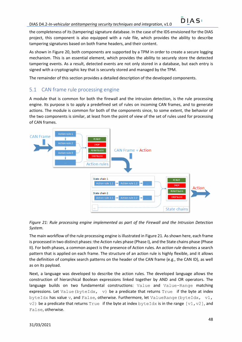
DIAS D4.2-In-vehicular antitampering security techniques and integration, v1.0
48 31/03/2021
the completeness of its (tampering) signature database. In the case of the IDS envisioned for the DIAS
project, this component is also equipped with a rule file, which provides the ability to describe
tampering signatures based on both frame headers, and their content.
As shown in Figure 20, both components are supported by a TPM in order to create a secure logging
mechanism. This is an essential element, which provides the ability to securely store the detected
tampering events. As a result, detected events are not only stored in a database, but each entry is
signed with a cryptographic key that is securely stored and managed by the TPM.
The remainder of this section provides a detailed description of the developed components.
5.1 CAN frame rule processing engine
A module that is common for both the firewall and the intrusion detection, is the rule processing
engine. Its purpose is to apply a predefined set of rules on incoming CAN frames, and to generate
actions. The module is common for both of the components since, to some extent, the behavior of
the two components is similar, at least from the point of view of the set of rules used for processing
of CAN frames.
Figure 21: Rule processing engine implemented as part of the Firewall and the Intrusion Detection System.
The main workflow of the rule processing engine is illustrated in Figure 21. As shown here, each frame
is processed in two distinct phases: the Action rules phase (Phase I), and the State chains phase (Phase
II). For both phases, a common aspect is the presence of Action rules. An action rule denotes a search
pattern that is applied on each frame. The structure of an action rule is highly flexible, and it allows
the definition of complex search patterns on the header of the CAN frame (e.g., the CAN ID), as well
as on its payload.
Next, a language was developed to describe the action rules. The developed language allows the
construction of hierarchical Boolean expressions linked together by AND and OR operators. The
language builds on two fundamental constructions: Value and Value-Range matching
expressions. Let Value(byteIdx, v) be a predicate that returns True if the byte at index
byteIdx has value v, and False, otherwise. Furthermore, let ValueRange(byteIdx, v1,
v2) be a predicate that returns True if the byte at index byteIdx is in the range [v1,v2], and
False, otherwise.
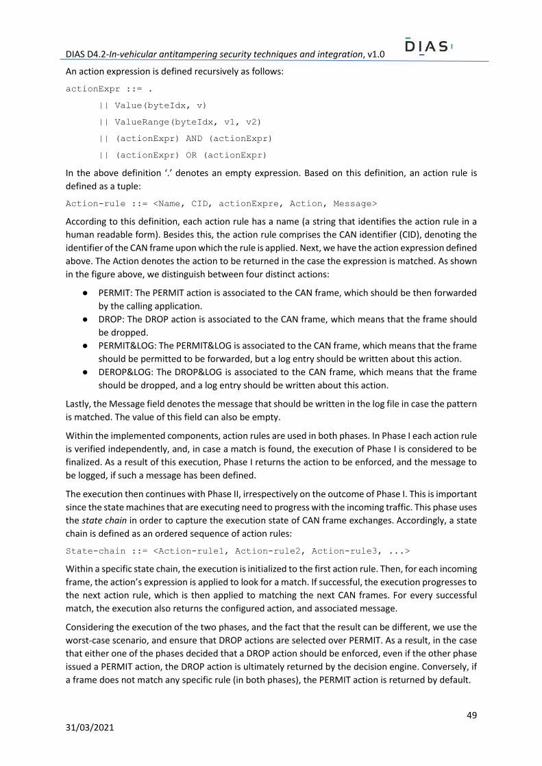
DIAS D4.2-In-vehicular antitampering security techniques and integration, v1.0
49 31/03/2021
An action expression is defined recursively as follows:
actionExpr ::= .
|| Value(byteIdx, v)
|| ValueRange(byteIdx, v1, v2)
|| (actionExpr) AND (actionExpr)
|| (actionExpr) OR (actionExpr)
In the above definition ‘.’ denotes an empty expression. Based on this definition, an action rule is
defined as a tuple:
Action-rule ::= <Name, CID, actionExpre, Action, Message>
According to this definition, each action rule has a name (a string that identifies the action rule in a
human readable form). Besides this, the action rule comprises the CAN identifier (CID), denoting the
identifier of the CAN frame upon which the rule is applied. Next, we have the action expression defined
above. The Action denotes the action to be returned in the case the expression is matched. As shown
in the figure above, we distinguish between four distinct actions:
● PERMIT: The PERMIT action is associated to the CAN frame, which should be then forwarded
by the calling application.
● DROP: The DROP action is associated to the CAN frame, which means that the frame should
be dropped.
● PERMIT&LOG: The PERMIT&LOG is associated to the CAN frame, which means that the frame
should be permitted to be forwarded, but a log entry should be written about this action.
● DEROP&LOG: The DROP&LOG is associated to the CAN frame, which means that the frame
should be dropped, and a log entry should be written about this action.
Lastly, the Message field denotes the message that should be written in the log file in case the pattern
is matched. The value of this field can also be empty.
Within the implemented components, action rules are used in both phases. In Phase I each action rule
is verified independently, and, in case a match is found, the execution of Phase I is considered to be
finalized. As a result of this execution, Phase I returns the action to be enforced, and the message to
be logged, if such a message has been defined.
The execution then continues with Phase II, irrespectively on the outcome of Phase I. This is important
since the state machines that are executing need to progress with the incoming traffic. This phase uses
the state chain in order to capture the execution state of CAN frame exchanges. Accordingly, a state
chain is defined as an ordered sequence of action rules:
State-chain ::= <Action-rule1, Action-rule2, Action-rule3, ...>
Within a specific state chain, the execution is initialized to the first action rule. Then, for each incoming
frame, the action’s expression is applied to look for a match. If successful, the execution progresses to
the next action rule, which is then applied to matching the next CAN frames. For every successful
match, the execution also returns the configured action, and associated message.
Considering the execution of the two phases, and the fact that the result can be different, we use the
worst-case scenario, and ensure that DROP actions are selected over PERMIT. As a result, in the case
that either one of the phases decided that a DROP action should be enforced, even if the other phase
issued a PERMIT action, the DROP action is ultimately returned by the decision engine. Conversely, if
a frame does not match any specific rule (in both phases), the PERMIT action is returned by default.

DIAS D4.2-In-vehicular antitampering security techniques and integration, v1.0
50 31/03/2021
The general workflow, and the decisioning process, are visualized in Figure 22.
Figure 22: Processing of rules and action results in the case of the two phases.
5.2 Firewall
As stated earlier, according to the monitored/filtered traffic, the firewall component comprises two
sub-modules: the CAN and the IP filtering modules. Each one can be instantiated and used
independently according to a specific scenario.
The CAN firewall (module) builds on the CAN frame rule processing engine. It leverages this engine in
order to apply a well-defined set of rules on CAN frames traversing the xCU/gateway that hosts the
firewall component. According to these rules, the firewall can either whitelist or blacklist specific
frames, and frame sequences. Whitelisting is applied in the case that specific frames are known to be
valid and not to cause any (known) harm to the vehicle. Conversely, blacklisting can be used to block
specific CAN frames that are known to cause damages/alter the behavior of the vehicle.
Since it leverages the above-described processing engine, the firewall supports both action and
stateful packet filtering. In the action-rule mode, the firewall applies a set of independent rules upon
each CAN frame. Conversely, in the case of the stateful processing mode, the firewall keeps track of
the transiting packets, and is able to blacklist/whitelist specific packets according to the transiting
context.
On the other hand, the IP firewall (module) leverages the packet filtering capabilities integrated into
the Linux kernel via NetFilter. The NetFilter framework is an important part of the Linux networking
DIAS D4.2-In-vehicular antitampering security techniques and integration, v1.0
51 31/03/2021
subsystem and consists of a core set of modules, tools and components that provide advanced
network filtering, connection tracking, and granular packet control at the kernel level. NetFilter
consists of kernel modules, user-space tools and other components that permit comprehensive
interaction with the network stack and hardware. The main features of the framework are:
- Filtering and firewall functionality provided by the xtables firewall architecture,
segmented by the NetFilter hook system into modules: eb_tables, arp_tables,
ip_tables, ip6_tables, nf_tables and their user-space counterparts: arptables,
ebtables, iptables, ip6tables, iptables-nftables/nft.
- Connection tracking provided by the conntrack module.
- Network Address Translation (NAT) through NAT helpers.
- Packet mangling and modifications, logging, queueing, and other various operations.
IpTables is the most used tool for interacting with the firewall component of the NetFilter framework
and its associated kernel modules. It functions at Layers 3-4 in the Open Systems Interconnection (OSI)
model, with limited filtering abilities at Layer 2, where ebtables and arptables provide better
functionality.
The Xtables architecture defines tables and chains of rules as base concepts upon which a firewall is
built. Tables are containers for predefined chains and describe a role for those chains. Each packet
that arrives at an interface, is assigned to a chain, depending on the packet’s destination (local
inbound, local outbound, transitioning). Chains are sets of rules that are processed sequentially, top
to bottom, where a packet that arrives at a network interface is compared to each rule the packet
corresponds to, and an action is taken based on that rule. In case the packet passes all rules, an
ultimate action is taken. This action is defined as the chain policy and can be configured for predefined
chains. Actions (targets) can be one of the following:
- built-in: ultimately, it decides whether a packet is accepted or not: ACCEPT, DROP, RETURN,
QUEUE.
- extension-defined: the packet may be classified, modified, marked, cloned, etc.
- jump to a user-defined chain (can be nested).
The integration of the NetFilter module in particular scenarios is performed via the logging extension
module of IpTables. Therefore, the logging functionality needs to be enabled in the kernel at compile
time. The CONFIG_IP_NF_TARGET_LOG flag needs to be enabled, for logging and the LOG target to be
recognized. When a rule is set with this target, the Linux kernel will output a log event in the kernel
logs.
Lastly, an important feature is the firewall’s ability to securely log the detected events. To this point,
in the case of both modules (CAN and IP filtering), detected events are securely logged by the
TPMLogger component. The component uses cryptographic keys protected by the TPM in order to
sign messages and to store them for later use and auditing. As a result, any event that is detected by
the firewall is securely logged, and any change to these logs will be detectable by verifying the
authenticity and integrity of the logs.
5.3 Intrusion detection system
Similarly to the firewall component, the developed intrusion detection system (IDS) takes advantage
of the CAN frame rule processing engine. The IDS monitors the CAN network for traffic, and it uses a
predefined set of rules for detecting tampering. Consequently, its performance is influenced by its
preconfigured set of rules. As a result, the developed IDS is a network-based IDS. As opposed to other
types of IDS (e.g., host-based), the advantage of using this type of component is that it is independent
DIAS D4.2-In-vehicular antitampering security techniques and integration, v1.0
52 31/03/2021
of the type of OS, software and architecture of communicating components (e.g., xCUs and digital
sensors). Furthermore, a network-based IDS can use complex signatures combining messages
originating from different sources.
Compared to the firewall, the IDS signals an intrusion, once it has happened. For this purpose, its set
of rules can encapsulate more complex constructions, with inspections at all available layers (both
header and payload). Furthermore, the IDS may be connected to several networks, and its input data
can originate from several distinct network sources. Consequently, more complex patterns can be
described, with packets from several distinct networks.
Opposed to the firewall, the output of the IDS is usually a detection event. The detection event is a
message that contains a description of the detected threat. In order to ensure the secure logging of
this event, the IDS leverages the secure logging features of the TPMLogger.
Lastly, it should be noted that both the firewall and the IDS generate decisions exclusively on the
available data (e.g., header and payload). In the case of encrypted (confidential) data, these
components cannot access the data, and therefore, cannot detect tampering attempts that leverage
such cryptographic techniques. Subsequently, since the firewall and the IDS are not in the possession
of cryptographic keys, they do not have the ability to verify the integrity (via authenticity) of CAN
frames. Additional implementation details related to the IDS module are provided in the following
sections.
6 Prototype integration and experimentation In order to demonstrate some of the security components described in the previous sections, namely
part of the key generation and distribution schemes, the stateless firewall and the Intrusion Detection
System (enhanced with the TPM), prototypes were implemented and experiments were conducted
on real testbeds.
6.1 Prototype implementations
In the following, the prototype implementations of part of the security components documented in
this deliverable are presented.
6.1.1 Key generation and distribution for xCU to xCU communication A prototype implementation of the key generation and distribution between xCUs as presented in
Section “3.2 Key management for xCUs” has been implemented in the Python programming
language. The Python module interacts with a real TPM module that handles the secure generation,
and storage of cryptographic keys.
The developed prototype leverages the tpm2-tools [TPM2T2021] to interact with the TPM, in this
case a TPM2-specification [TPM2Specs2019] compatible security controller. The module provides
basic features for generating Storage Root Keys (SRK), Key Signing Keys (KSK), Key Distribution Keys
(KDK), and Session Keys (SK). The implementation is structured across several source files that
implement the necessary features for showcasing the key generation functions.
The implementation details are listed in Annex B. Accordingly, CAN messages can then be used to
exchange the generated keys.
6.1.2 Enhanced SecOC Both symmetric and asymmetric encryption are used to secure communications in the Enhanced
SecOC solution for the DIAS project. Symmetric encryption is used to transfer securely the Service

DIAS D4.2-In-vehicular antitampering security techniques and integration, v1.0
53 31/03/2021
Provider certificate from the mobile device to the vehicle and more specifically to an API endpoint
inside the vehicle, which waits to receive, decrypt, store and send the certificate to the CCU. This is to
prevent and stop a middle man to sniff the authentic certificate information during certificate transfer.
ECDH key agreement protocol is used for asymmetric encryption in order to generate the shared key
between the parts that desire to achieve communication with the use of the Enhanced SecOC. In order
to access a utility in the xCU, the Tester (Service Provider) has to communicate with the CCU. The CCU
has two main targets. First, it checks with the Certificate Authority the authenticity and the validity of
the Certificate, which was sent from the Tester. Second, it sends the xCU’s Public key to the Tester
and the Tester’s Public key to the xCU. The xCU and the Tester make use of the received certificates
to generate the same secret key with ECDH in order to use it for Enhanced SecOC. [Autosar2017]
The flow of Enhanced SecOC secure communication is the following (see Figure 23):
1. The Tester (Service Provider) requests authenticated communication with xCU.
2. The CCU validates the Message Authentication Code (MAC) and accepts the request.
3. The CCU sends the xCU’s Public Key to the Tester.
4. The CCU sends the Tester’s Public Key to the xCU.
5. The Tester validates the Message Authentication Code (MAC) and derives the shared key xCU-
Tester for Enhanced SecOC communication.
6. The xCU validates the Message Authentication Code (MAC) and derives the shared key xCU-
Tester for Enhanced SecOC communication.
7. The Tester sends an authenticated request to the xCU with Enhanced SecOC.
8. The xCU validates the Message Authentication Code (MAC) and responds to the request.
Figure 23: Tester Authenticated Communication with xCU.
The CCU exchanges keys between authenticated devices only. An authenticated device is a device
whose identity has been verified by the CCU and also the following pre-requisites exist:
• The CCU has the public key of the authenticated device.
• An authenticated device has the public key of the CCU.
Hence, the two parties can have an authenticated communication, through the Enhanced SecOC.
Next, the process of authenticating a device (i.e., a Tester Device) is the following:
DIAS D4.2-In-vehicular antitampering security techniques and integration, v1.0
54 31/03/2021
• A CA server issues a certificate for the tester device.
• The tester device gets the certificate and the corresponding private key (encrypted through
API).
• The tester device sends the certificate through the CAN bus to the CCU.
• The CCU checks if the certificate is valid.
• The CCU communicates with the CA Server to check if the certificate has been revoked.
• If the response of the CA server indicates successful validation, then the device is
authenticated.
• The CCU extracts the public key of the tester from the certificate.
• The CCU sends its public key to the tester.
• Now the tester and the CCU can derive the same shared secret key. Therefore, they can have
an authenticated communication through Enhanced SecOC.
6.1.3 Firewall and intrusion detection As already mentioned, both the firewall, and the intrusion detection build on the same CAN frame
rule processing engine. A prototype of the CAN frame processing engine has been implemented in the
C++ language. The engine can be used as a library (e.g., Dynamic Link Library) that exposes a simple
API for creating a new instance, and for processing frames according to the preconfigured set of rules.
The API and its description have been included in Annex C.
Based on this API, the firewall and intrusion detection system can be implemented. As mentioned
earlier, the difference between the two components lies in the complexity of their rules. The intrusion
detection may include more rules with complex deep packet processing expressions. The rules are
described in an XML (eXtensible Markup Language) file. The choice in using this approach stems from
the flexibility of the XML language, and its ability to define hierarchical constructions. At its core, the
configuration file builds on action rules, which are defined between “rule” elements. Each rule
element includes as properties, the CAN identifier, and a unique string identifier. The string identifier
is used to link with the action rules and stateful rule chains. Subsequently, each rule contains the
“payload” element, which defines the deep packet processing and matching statements. An example
rule is the following:
<rule cid="23" id="obd_diag">
<payload>
<expression>
<operator type="AND">
<byte index="0" value="10"/>
<byte index="1" value-range="2..10"/>
</operator>
</expression>
</payload>
</rule>
In the example above, the rule identifies the CAN frame with the “23” identifier, for which the first
byte in the payload is 10, while the second byte is in the range of 2-10. As described in the previous
sections, the language used to describe rules supports hierarchical expressions for matching values in
CAN payloads. Accordingly, a more complex construction is given below:
<rule cid="23" id="obd_diag_ex">
<payload>
<expression>
<operator type="AND">
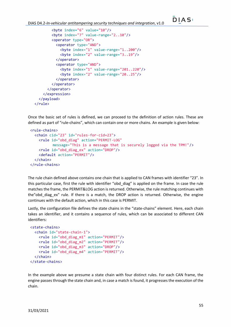
DIAS D4.2-In-vehicular antitampering security techniques and integration, v1.0
55 31/03/2021
<byte index="6" value="10"/>
<byte index="7" value-range="2..10"/>
<operator type="OR">
<operator type="AND">
<byte index="1" value-range="1..200"/>
<byte index="2" value-range="3..19"/>
</operator>
<operator type="AND">
<byte index="1" value-range="201..220"/>
<byte index="2" value-range="20..25"/>
</operator>
</operator>
</operator>
</expression>
</payload>
</rule>
Once the basic set of rules is defined, we can proceed to the definition of action rules. These are
defined as part of “rule-chains”, which can contain one or more chains. An example is given below:
<rule-chains>
<chain cid="23" id="rules-for-cid=23">
<rule id="obd_diag" action="PERMIT-LOG"
message="This is a message that is securely logged via the TPM!"/>
<rule id="obd_diag_ex" action="DROP"/>
<default action="PERMIT"/>
</chain>
</rule-chains>
The rule chain defined above contains one chain that is applied to CAN frames with identifier “23”. In
this particular case, first the rule with identifier “obd_diag” is applied on the frame. In case the rule
matches the frame, the PERMIT&LOG action is returned. Otherwise, the rule matching continues with
the"obd_diag_ex" rule. If there is a match, the DROP action is returned. Otherwise, the engine
continues with the default action, which in this case is PERMIT.
Lastly, the configuration file defines the state chains in the “state-chains” element. Here, each chain
takes an identifier, and it contains a sequence of rules, which can be associated to different CAN
identifiers:
<state-chains>
<chain id="state-chain-1">
<rule id="obd_diag_m1" action="PERMIT"/>
<rule id="obd_diag_m2" action="PERMIT"/>
<rule id="obd_diag_m3" action="DROP"/>
<rule id="obd_diag_m4" action="PERMIT"/>
</chain>
</state-chains>
In the example above we presume a state chain with four distinct rules. For each CAN frame, the
engine passes through the state chain and, in case a match is found, it progresses the execution of the
chain.
DIAS D4.2-In-vehicular antitampering security techniques and integration, v1.0
56 31/03/2021
For demonstrating the functionality of the rule processing engine, a communication module was
implemented. This module creates a new engine instance, it reads CAN frames from a CAN interface,
and it calls a function from the firewall API (see Annex C for the implementation details). In case a LOG
action is returned, the module also sends the message that needs to be securely logged via the TPM.
By leveraging the features of the TPM, both the firewall and IDS have been enhanced with secure
logging capabilities. Secure logging entails that the generated logs are signed via a secret key. The
secret key is sealed with the TPM’s SRK, which, as mentioned before, cannot be read outside the TPM.
As a result, new logs cannot be written, while previous logs cannot be modified. This feature is
particularly useful in case tamperers try to cover their tracks by changing/erasing different flags/logs.
With the secure logging feature, tamperers cannot cover their tracks, since logs can only be
written/changed by the owner of the signing key, which in this case is the TPM.
6.2 Developed testbed for demonstrating the security features
The vehicle architecture, as shown in Figure 3, was used as a reference architecture in the creation of
the testbed. The testbed comprises three network nodes, two of them simulating xCUs, and a third
node simulating digital sensors. Each of the first two network nodes (that simulate xCUs) has the
following configuration:
● Raspberry Pi model 3B+ running the Automotive Grade Linux operating system.
● An MCP2515 CAN controller, with a TJA1050 CAN transceiver.
● An Infineon OPTIGA SLB 9670 Trusted Platform Module.
The third node is implemented with the help of the µLC Test System from BOSCH. The µLC Test System
is an open-loop test environment for xCUs. The device offers the possibility of simulating automotive
sensors as well as communication protocols; it supports typical interfaces for sensors and bus systems
(e.g., analog/digital inputs and outputs, PWM signals, SENT, CAN, LIN). Furthermore, all the manual
operations, the automation, as well as the connection to the device, can be controlled via an
application programming interface.
The architecture of the testbed is shown in Figure 24. Here, all 3 nodes mentioned earlier are clearly
visible, namely the µLC Test System connected to the CAN bus, and the two Raspberry Pi boards
connected to the CAN bus via the previously mentioned CAN controllers, each one having attached a
TPM.
Based on the above-described testbed, the data flow normally present in a real vehicle was simulated.
The dataset used in the experimental phase was provided by TNO partner, as a result of the tests and
measurements documented in Deliverable 2.2. The dataset contains SAE J1939 CAN frames extracted
from the Ford Otosan demonstration truck; a total of 100000 frames, including Aftertreatment related
signals, with 11 individual CAN identifiers.

DIAS D4.2-In-vehicular antitampering security techniques and integration, v1.0
57 31/03/2021
Figure 24: The physical testbed at UMFST partner’s premises used to demonstrate the main features of the Firewall and IDS, both equipped with TPM capabilities (e.g., key generation, secure logging).
6.3 Experiment setup
For the following experiments, in order to properly simulate a real vehicle network, three additional
software components were added to emulate typical in-vehicle xCUs/digital sensors: the
DataSender, the DataReceiver, and a custom MATLAB script for the µLC Test System.
The DataSender consists of a python script that replays existing CAN frames stored in log files (see
CAN Trace LOG File in Figure 25). The module takes as input different types of log files (e.g., .asc,
.log, .blf or .csv) and replays the stored frames directly on the CAN bus. The frames can either be sent
at the recorded cycle times or at a specified periodicity.
Similarly to the DataSender, the DataReceiver is a python script that listens for incoming traffic
on the CAN bus and forwards the received frames directly to the Stateful Firewall and IDS
modules by using inter-process communication techniques (e.g., named pipes).
Finally, using a MATLAB script, the µLC Test System was used to emulate tampered components
(e.g., xCUs, and digital sensors). In the case of experiments involving the Firewall components, the
tampering consisted in a man-in-the-middle “attack” during the diagnostics process of xCUs. In this
scenario the tamperer (µLC Test System) injects Diagnostic Trouble Code Erase requests in order
to clear the active and previous Diagnostic codes. In a similar way, for the IDS, the µLC Test System
was used to simulate an aftertreatment tampering by sending modified frames, containing altered
signals.

DIAS D4.2-In-vehicular antitampering security techniques and integration, v1.0
58 31/03/2021
Figure 25: Data Flow Diagram illustrating the interacting components used throughout the experiments.
Table 4: Computed payload [MIN, MAX] intervals for each byte.
CID
Payload [MIN, MAX]
Byte 1 Byte 2 Byte 3 Byte 4 Byte 5 Byte 6 Byte 7 Byte 8
217911633 [15, 51] 5 230 3 124 137 0 255
418385489 255 255 255 255 255 255 255 255
418385746 [0,254] [16,98] [0,255] [154,246] 85 159 31 255
419273635 54 130 255 31 31 243 255 255
419321507 [213,250] 55 [50,90] 20 31 31 255 255
6.3.1 Firewall and IDS rule creation
Recall that firewall rules are built using the individual CAN message identifiers. To extract all the
individual identifiers from the dataset, a MATLAB script was used. Firstly, a list containing all the
identifiers was created. Secondly, for each individual identifier an action rule was created. Lastly, the
action rules were combined to create the state chains. For the firewall component (for demonstration
purposes), multiple state chains were created containing all possible decisions, namely PERMIT, DROP,
PERMIT&LOG, DROP&LOG.
In a similar manner, the creation of the IDS rules included an initial analysis of the dataset. First, the
individual identifiers were extracted, and then, the payloads were analyzed. As the IDS can perform
deep packet inspection, the rules also included certain conditions for each byte in the payload.

DIAS D4.2-In-vehicular antitampering security techniques and integration, v1.0
59 31/03/2021
The steps taken in creating the IDS rules are the following:
• for each individual CAN identifier the MIN and MAX values for each byte from the payload
were computed. Some of the computed values have been illustrated in Table 4.
• for each CAN identifier, an action rule was generated, where, for each byte, the previously
computed [MIN, MAX] interval was set. An example of a rule automatically generated based
on the previous computations is given below:
<rule cid="217911633" id="217911633_permit">
<source network="OUTSIDE"/>
<destination network="CAN1"/>
<payload>
<expression>
<operator type="AND">
<byte index="0" value-range="15..51"/>
<byte index="1" value="5"/>
<byte index="2" value="230"/>
<byte index="3" value="3"/>
<byte index="4" value="124"/>
<byte index="5" value="137"/>
<byte index="6" value="0"/>
<byte index="7" value="255"/>
</operator>
</expression>
</payload>
</rule>
Based on the assumption that valid values would fall within the computed [MIN, MAX] interval, for
each byte a PERMIT action was generated. Furthermore, PERMIT&LOG as well as DROP&LOG actions
were automatically generated for values falling outside of [MIN, MAX]. Similarly, custom rules were
created for the frames injected by the µLC test system.
6.3.2 Secure Logging setup
As mentioned in sections 4.4.1 and 4.4.2 the secure logging module uses cryptographic keys protected
by the TPM in order to sign the received messages. For this purpose, the secure logging module was
initialized by generating an authentication cryptographic key, sealed with the TPM’s SRK.
6.4 Experimental results
According to the previously described setup for each component, the PERMIT/DROP and
PERMIT&LOG/DROP&LOG were validated. Subsequently, the execution times for each action that can
be performed by the Stateful Firewall and IDS were measured according to the testbed specification
presented earlier.
The workflow used for validating the components is similar in both cases. The only difference is in the
way the input CAN frames are processed. While the Stateful Firewall processes sequences of frames
based on their identifiers, the IDS processes and analyzes the ranges of bytes in the frame’s data field
as well.
At the start of each experiment, the tested component was pre-configured accordingly. Afterwards,
the simulated CAN frames were generated by using an input CAN trace log file with the help of the
DataSender component. Next, the captured CAN frames were forwarded to the Stateful Firewall
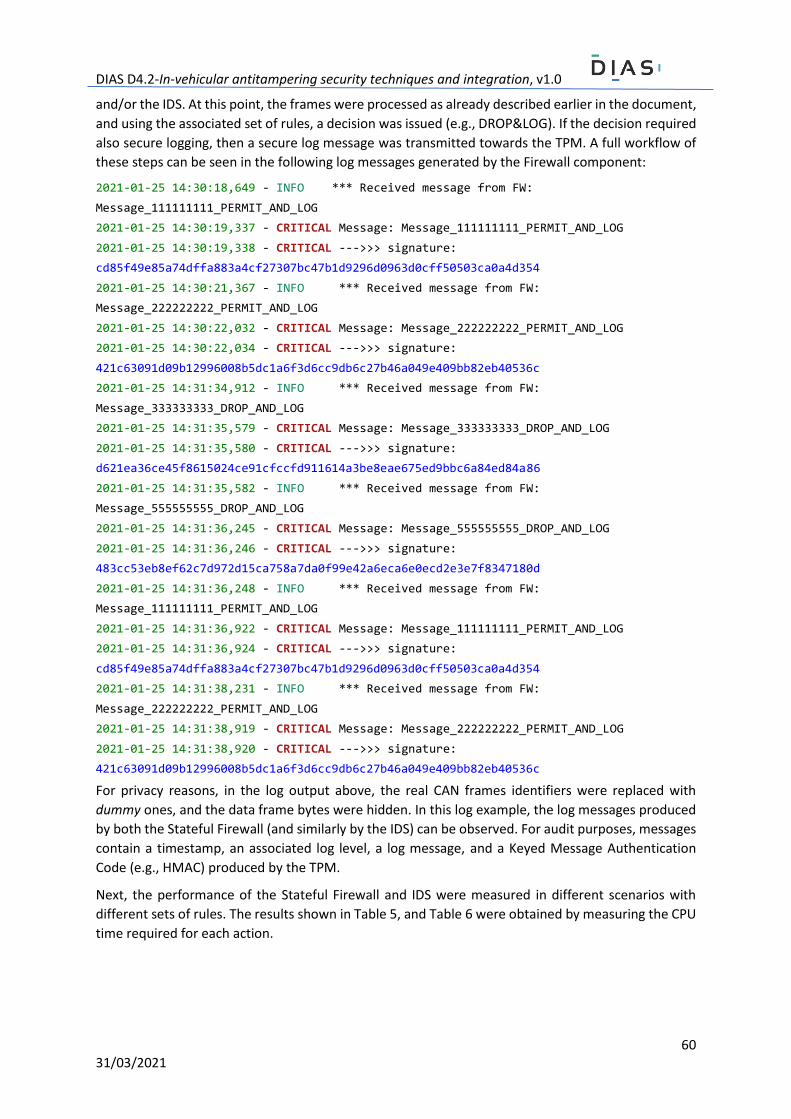
DIAS D4.2-In-vehicular antitampering security techniques and integration, v1.0
60 31/03/2021
and/or the IDS. At this point, the frames were processed as already described earlier in the document,
and using the associated set of rules, a decision was issued (e.g., DROP&LOG). If the decision required
also secure logging, then a secure log message was transmitted towards the TPM. A full workflow of
these steps can be seen in the following log messages generated by the Firewall component:
2021-01-25 14:30:18,649 - INFO *** Received message from FW:
Message_111111111_PERMIT_AND_LOG
2021-01-25 14:30:19,337 - CRITICAL Message: Message_111111111_PERMIT_AND_LOG
2021-01-25 14:30:19,338 - CRITICAL --->>> signature:
cd85f49e85a74dffa883a4cf27307bc47b1d9296d0963d0cff50503ca0a4d354
2021-01-25 14:30:21,367 - INFO *** Received message from FW:
Message_222222222_PERMIT_AND_LOG
2021-01-25 14:30:22,032 - CRITICAL Message: Message_222222222_PERMIT_AND_LOG
2021-01-25 14:30:22,034 - CRITICAL --->>> signature:
421c63091d09b12996008b5dc1a6f3d6cc9db6c27b46a049e409bb82eb40536c
2021-01-25 14:31:34,912 - INFO *** Received message from FW:
Message_333333333_DROP_AND_LOG
2021-01-25 14:31:35,579 - CRITICAL Message: Message_333333333_DROP_AND_LOG
2021-01-25 14:31:35,580 - CRITICAL --->>> signature:
d621ea36ce45f8615024ce91cfccfd911614a3be8eae675ed9bbc6a84ed84a86
2021-01-25 14:31:35,582 - INFO *** Received message from FW:
Message_555555555_DROP_AND_LOG
2021-01-25 14:31:36,245 - CRITICAL Message: Message_555555555_DROP_AND_LOG
2021-01-25 14:31:36,246 - CRITICAL --->>> signature:
483cc53eb8ef62c7d972d15ca758a7da0f99e42a6eca6e0ecd2e3e7f8347180d
2021-01-25 14:31:36,248 - INFO *** Received message from FW:
Message_111111111_PERMIT_AND_LOG
2021-01-25 14:31:36,922 - CRITICAL Message: Message_111111111_PERMIT_AND_LOG
2021-01-25 14:31:36,924 - CRITICAL --->>> signature:
cd85f49e85a74dffa883a4cf27307bc47b1d9296d0963d0cff50503ca0a4d354
2021-01-25 14:31:38,231 - INFO *** Received message from FW:
Message_222222222_PERMIT_AND_LOG
2021-01-25 14:31:38,919 - CRITICAL Message: Message_222222222_PERMIT_AND_LOG
2021-01-25 14:31:38,920 - CRITICAL --->>> signature:
421c63091d09b12996008b5dc1a6f3d6cc9db6c27b46a049e409bb82eb40536c
For privacy reasons, in the log output above, the real CAN frames identifiers were replaced with
dummy ones, and the data frame bytes were hidden. In this log example, the log messages produced
by both the Stateful Firewall (and similarly by the IDS) can be observed. For audit purposes, messages
contain a timestamp, an associated log level, a log message, and a Keyed Message Authentication
Code (e.g., HMAC) produced by the TPM.
Next, the performance of the Stateful Firewall and IDS were measured in different scenarios with
different sets of rules. The results shown in Table 5, and Table 6 were obtained by measuring the CPU
time required for each action.
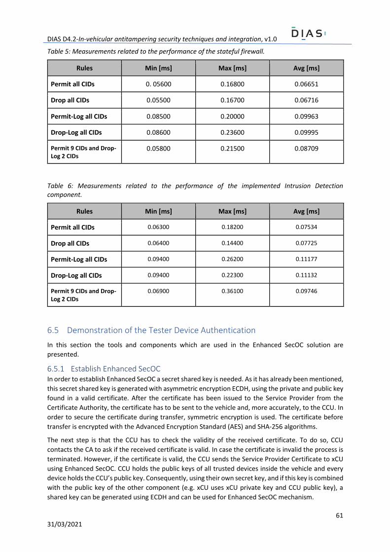
DIAS D4.2-In-vehicular antitampering security techniques and integration, v1.0
61 31/03/2021
Table 5: Measurements related to the performance of the stateful firewall.
Rules Min [ms] Max [ms] Avg [ms]
Permit all CIDs 0. 05600 0.16800 0.06651
Drop all CIDs 0.05500 0.16700 0.06716
Permit-Log all CIDs 0.08500 0.20000 0.09963
Drop-Log all CIDs 0.08600 0.23600 0.09995
Permit 9 CIDs and Drop-Log 2 CIDs
0.05800 0.21500 0.08709
Table 6: Measurements related to the performance of the implemented Intrusion Detection component.
Rules Min [ms] Max [ms] Avg [ms]
Permit all CIDs 0.06300 0.18200 0.07534
Drop all CIDs 0.06400 0.14400 0.07725
Permit-Log all CIDs 0.09400 0.26200 0.11177
Drop-Log all CIDs 0.09400 0.22300 0.11132
Permit 9 CIDs and Drop-Log 2 CIDs
0.06900 0.36100 0.09746
6.5 Demonstration of the Tester Device Authentication
In this section the tools and components which are used in the Enhanced SecOC solution are
presented.
6.5.1 Establish Enhanced SecOC In order to establish Enhanced SecOC a secret shared key is needed. As it has already been mentioned,
this secret shared key is generated with asymmetric encryption ECDH, using the private and public key
found in a valid certificate. After the certificate has been issued to the Service Provider from the
Certificate Authority, the certificate has to be sent to the vehicle and, more accurately, to the CCU. In
order to secure the certificate during transfer, symmetric encryption is used. The certificate before
transfer is encrypted with the Advanced Encryption Standard (AES) and SHA-256 algorithms.
The next step is that the CCU has to check the validity of the received certificate. To do so, CCU
contacts the CA to ask if the received certificate is valid. In case the certificate is invalid the process is
terminated. However, if the certificate is valid, the CCU sends the Service Provider Certificate to xCU
using Enhanced SecOC. CCU holds the public keys of all trusted devices inside the vehicle and every
device holds the CCU’s public key. Consequently, using their own secret key, and if this key is combined
with the public key of the other component (e.g. xCU uses xCU private key and CCU public key), a
shared key can be generated using ECDH and can be used for Enhanced SecOC mechanism.
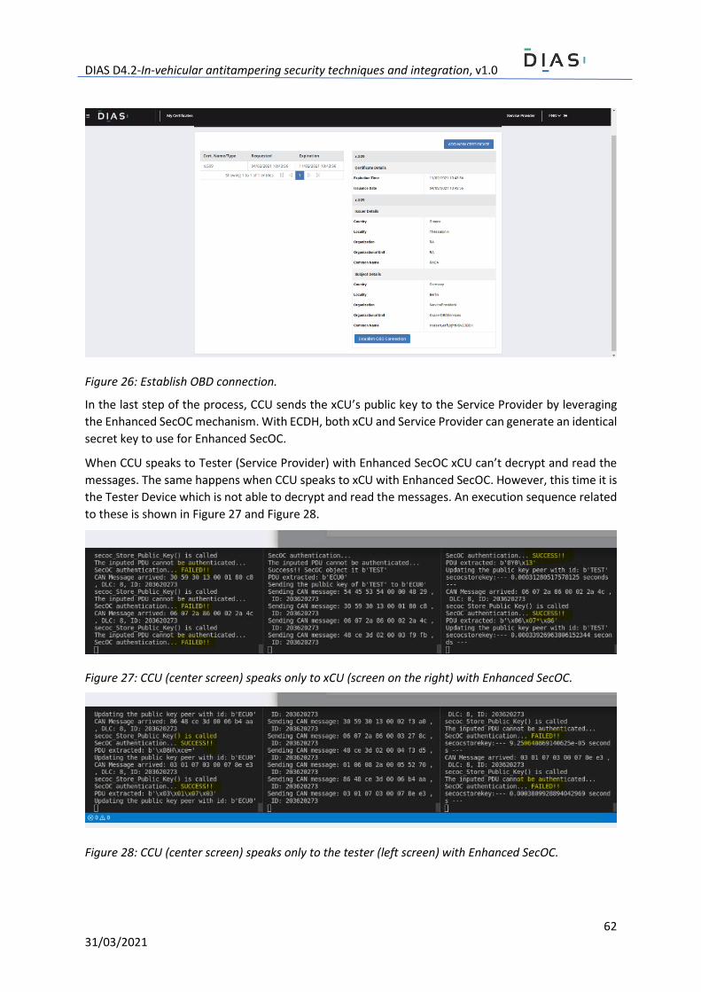
DIAS D4.2-In-vehicular antitampering security techniques and integration, v1.0
62 31/03/2021
Figure 26: Establish OBD connection.
In the last step of the process, CCU sends the xCU’s public key to the Service Provider by leveraging
the Enhanced SecOC mechanism. With ECDH, both xCU and Service Provider can generate an identical
secret key to use for Enhanced SecOC.
When CCU speaks to Tester (Service Provider) with Enhanced SecOC xCU can’t decrypt and read the
messages. The same happens when CCU speaks to xCU with Enhanced SecOC. However, this time it is
the Tester Device which is not able to decrypt and read the messages. An execution sequence related
to these is shown in Figure 27 and Figure 28.
Figure 27: CCU (center screen) speaks only to xCU (screen on the right) with Enhanced SecOC.
Figure 28: CCU (center screen) speaks only to the tester (left screen) with Enhanced SecOC.
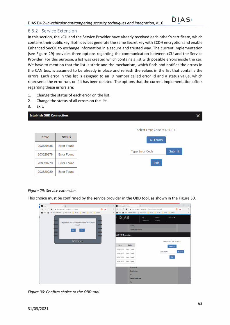
DIAS D4.2-In-vehicular antitampering security techniques and integration, v1.0
63 31/03/2021
6.5.2 Service Extension In this section, the xCU and the Service Provider have already received each other’s certificate, which
contains their public key. Both devices generate the same Secret key with ECDH encryption and enable
Enhanced SecOC to exchange information in a secure and trusted way. The current implementation
(see Figure 29) provides three options regarding the communication between xCU and the Service
Provider. For this purpose, a list was created which contains a list with possible errors inside the car.
We have to mention that the list is static and the mechanism, which finds and notifies the errors in
the CAN bus, is assumed to be already in place and refresh the values in the list that contains the
errors. Each error in this list is assigned to an ID number called error id and a status value, which
represents the error runs or if it has been deleted. The options that the current implementation offers
regarding these errors are:
1. Change the status of each error on the list.
2. Change the status of all errors on the list.
3. Exit.
Figure 29: Service extension.
This choice must be confirmed by the service provider in the OBD tool, as shown in the Figure 30.
Figure 30: Confirm choice to the OBD tool.
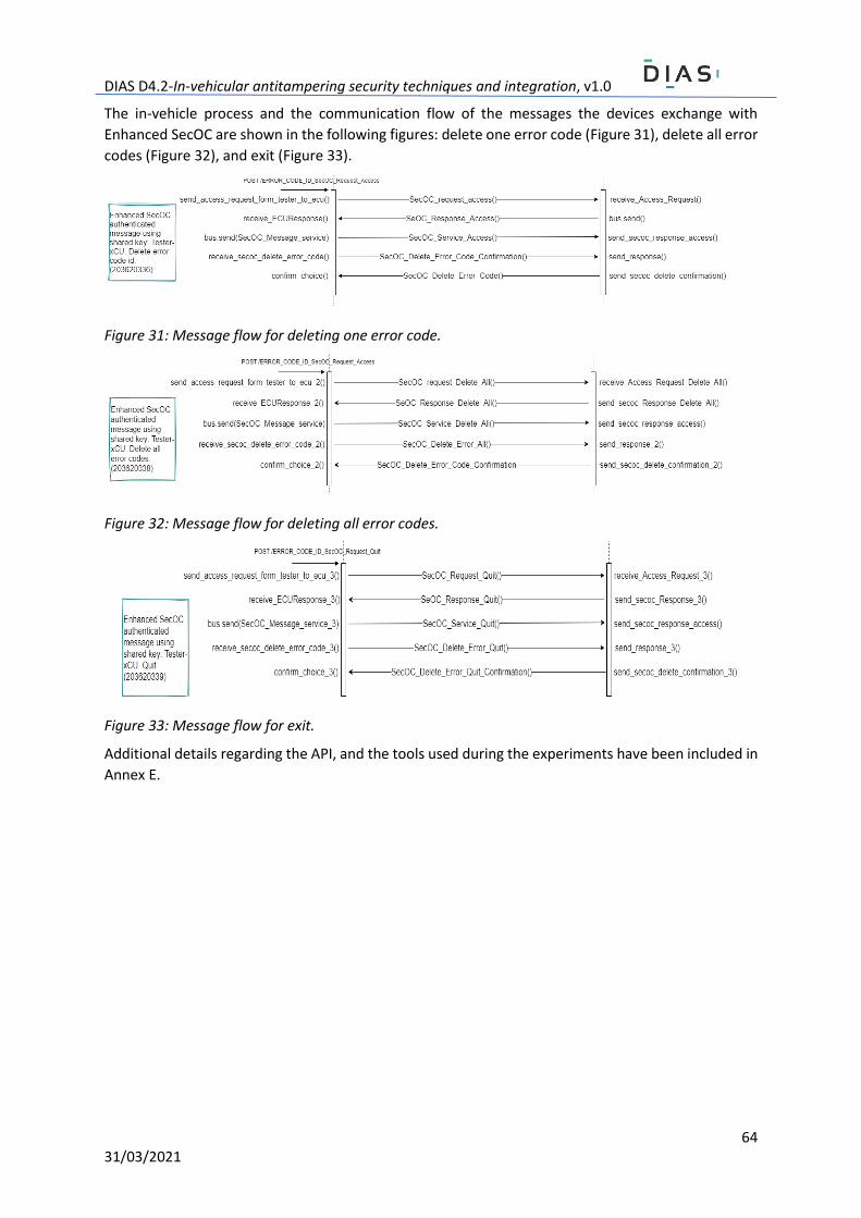
DIAS D4.2-In-vehicular antitampering security techniques and integration, v1.0
64 31/03/2021
The in-vehicle process and the communication flow of the messages the devices exchange with
Enhanced SecOC are shown in the following figures: delete one error code (Figure 31), delete all error
codes (Figure 32), and exit (Figure 33).
Figure 31: Message flow for deleting one error code.
Figure 32: Message flow for deleting all error codes.
Figure 33: Message flow for exit.
Additional details regarding the API, and the tools used during the experiments have been included in
Annex E.
DIAS D4.2-In-vehicular antitampering security techniques and integration, v1.0
65 31/03/2021
Conclusions According to the analyzed solutions and to the results documented in this deliverable, the
development of an in-vehicle solution for securing all of the components and communications is
challenging. Nevertheless, the following can be concluded:
● Existing security techniques, as well as new techniques that have been documented in this
deliverable, together with future development planned for the remainder of this project, are
applicable to digital sensors (i.e., sensors that use some form of digital communication), while
securing analog communications is considered out of scope of the DIAS project.
● In-vehicle digital communications need to be secured both in the case of xCU to xCU
communications, as well as between xCU to SCU, and SCU to digital sensor communication.
However, securing communications with digital sensors is challenging, mainly because of their
limited computational capabilities. As a result, the deliverable described several approaches
that take into account the limited computational power of digital sensors.
● Cryptographic key distribution protocols aimed at securing communications with critical
components such as xCUs need to use modern cryptographic techniques (i.e., asymmetric
cryptography). This is needed so that the integrated security schemes can withstand not only
the tampering techniques known today, but also possible future techniques that may leverage
more powerful devices.
● To empower xCUs with modern cryptographic techniques, the use of cryptographic co-
processors such as a TPM is highly recommended. TPMs are capable of executing advanced
cryptographic computations in a secure manner. The isolation from the main processor means
that TPMs are tamper proof, and are able to protect cryptographic keys, and secrets in general
(e.g., passwords, session keys).
● Securing communications with digital sensors, as well as the development of key distribution
protocols for scenarios in which digital sensors are present, requires specially tailored
techniques that account for their computational limitations, as well as for the sensor diversity.
To this end, the deliverable documented several solutions that leverage symmetric techniques
alongside cryptographic hash functions in a way that permits both the sensor, and the more
powerful xCU/SCU to authenticate data exchanges, and to establish new session keys.
● Cryptographic protocols for securing in-vehicle communications need to consider existing
standards and recommendations in the field. To this end, the developed techniques are based
on the recommendations set forth by AUTOSAR Specification of Secure Onboard
Communication standard (AUTOSAR SecOC) [Autosar2017]. As a result, the documented
protocols leverage efficient techniques to enforce data integrity and authentication by
leveraging cryptographic hash functions in the computation of Message Authentication Codes
(MACs). Furthermore, in all of the cases a special emphasis was placed on ensuring freshness
of authenticated CAN frames.
● Other techniques such as secure boot, secure firmware update, and address space
randomization can further enhance the in-vehicle security and increase the level of
sophistication (i.e., and cost) of future tampering attempts.
● Firewall components, including their main features adapted from the traditional field of ICT
security can help in the implementation of effective “defense-in-depth” strategies in the case
of in-vehicle communications. Firewalls, strategically positioned, can filter malicious traffic,
and can block tampering attempts that leverage digital communications. However,
considering the diversity of communication interfaces available within the modern vehicle,
firewalls need to account for this diversity. Accordingly, the firewall documented in this
deliverable processes not only traditional IP traffic, but also in-vehicle CAN traffic.
DIAS D4.2-In-vehicular antitampering security techniques and integration, v1.0
66 31/03/2021
● Similarly to the firewall component, an Intrusion Detection System (IDS) was also documented
in this deliverable. The IDS leverages the same rule processing engine as the firewall, but it
focuses only on CAN traffic in order to detect tampering. Furthermore, the IDS also performs
“deep packet inspection” by looking not only at the frame’s header but also at its payload, in
order to detect more sophisticated tampering. A notable aspect in the development of both
components (i.e., the firewall and the IDS) is their enhancement with secure logging
capabilities, supported by the TPM.
This deliverable also included preliminary experimental results. These results demonstrate the
feasible application of several techniques in order to alleviate tampering from a cyber security
perspective. Nevertheless, as already mentioned, the project partners intend to further explore other
directions, and to refine/adapt the developed techniques according to the experimental results, the
results of the hackathon events, and the integration tests that will follow.
DIAS D4.2-In-vehicular antitampering security techniques and integration, v1.0
67 31/03/2021
References [Acea2017] European Automotive Manufacturers Association, “Truck manufacturers call for action to
prevent aftermarket manipulation of emissions controls,” ACEA Press release, February 28, 2017 [On-
line] https://www.acea.be/press-releases/article/truck-manufacturers-call-for-action-to-prevent-
aftermarket-manipulation-of , last accessed february 26, 2021.
[Aga2019] M.T. Aga, and T. Austin, “Smokestack: Thwarting DOP Attacks with Runtime Stack Layout
Randomization,” In Proceedings of the 2019 IEEE/ACM International Symposium on Code Generation
and Optimization (CGO), Washington, DC, USA, 16–20 February 2019.
[Autosar2017] AUTOSAR SecOC, “Specification of Secure Onboard Communication AUTOSAR CP
Release 4.3.1,” AUTOSAR, 2017.
[Bellovin2004] S. Bellovin, W. Cheswic, “Privacy-Enhanced Searches Using Encrypted Bloom Filters,”
Technical Report CUCS-034-07, 2007.
[Bißmeyer2016] N. Bißmeyer, “Security in ecu production,” ETAS white paper,
https://www.etas.com/data/RealTimes_2016/rt_2016_1_05_en.pdf, 2016.
[Bloom1970] B. H. Bloom, “Space/Time Trade-offs in Hash Coding with Allowable Errors,” Commun.
ACM, vol. 13, no. 7, pp. 422–426, Jul. 1970.
[Buchmann2013] J. Buchmann, “Introduction to Cryptography,” Springer Science +Business Media, pp.
186-188, 2013.
[Christensen2010] K. Christensen, A. Roginsky, M. Jimeno, “A new analysis of the false positive rate of
a Bloom filter,” Information Processing Letters, Volume 110, Issue 21, 2010, Pages 944-949.
[Cremers2012] C. Cremers, S. Mauw, “Multi-protocol attacks,” in: Operational Semantics and
Verification of Security Protocols, Springer Berlin Heidelberg, Berlin, Heidelberg, 2012, pp. 107–122.
[Cremers2008] C. Cremers, “The Scyther Tool: Verification, falsification, and analysis of security
protocols,” in: Computer Aided Verification, 20th International Conference, CAV 2008, Princeton, USA,
Proc., in: Lecture Notes in Computer Science, 5123/2008, Springer, 2008, pp. 414–418.
[Cremers2016] C. Cremers, M. Horvat, S. Scott, T. van der Merwe, “Automated analysis and
verification of TLS 1.3: 0-RTT, resumption and delayed authentication,” in: IEEE Symposium on Security
and Privacy, IEEE Computer Society, 2016, pp. 470–485.
[DH1976] W. Diffie, M.E. Hellman, “New Directions in Cryptography,“ IEEE Transactions on Information
Theory, November 1976, 22 (6): 644–654.
[Dolev2006] D. Dolev, A. Yao, “On the security of public key protocols,” IEEE Trans. Inform. Theory 29
(2) (2006) 198–208.
[ElGamal1985] T. ElGamal, “A Public-Key Cryptosystem and a Signature Scheme Based on Discrete
Logarithms,” IEEE Transactions on Information Theory. 31 (4), 1985, pp. 469–472.
[ENISA2019] The European Union Agency for Cybersecurity, “ENISA good practices for security of
smart cars,” November 25, 2019.
[Foster2005] J. Foster, et al., “Buffer Overflow attacks,” Burlington: Syngress, 2005.
[IETF2021] M. Jones, J. Bradley, N. Sakimura, “JSON Web Token (JWT),” FRC 7519, May 2015,
https://tools.ietf.org/html/rfc7519, last accessed February 22, 2021.
DIAS D4.2-In-vehicular antitampering security techniques and integration, v1.0
68 31/03/2021
[ISO2003] International Organization for Standardization, “ISO 11898-1:2003 - Road vehicles -
Controller area network (CAN) - Part 1: Data link layer and physical signalling,” 2003.
[JSON2021] JWT, “Introduction to JSON Web Tokens,” https://jwt.io/introduction/, last accessed
February 18, 2021.
[Keleman2019] L. Keleman, D. Matić, M. Popović and I. Kaštelan, “Secure firmware update in
embedded systems,” 2019 IEEE 9th International Conference on Consumer Electronics (ICCE-Berlin),
Berlin, Germany, 2019, pp. 16-19.
[Lenard2020LOKI] T. Lenard, R. Bolboacă and B. Genge, “LOKI: A Lightweight Cryptographic Key
Distribution Protocol for Controller Area Networks,” 2020 IEEE 16th International Conference on
Intelligent Computer Communication and Processing (ICCP), Cluj-Napoca, Romania, 2020, pp. 513-
519.
[Lenard2020MixCAN] T. Lenard, R. Bolboacă, B. Genge and P. Haller, “MixCAN: Mixed and Backward-
Compatible Data Authentication Scheme for Controller Area Networks,” 2020 IFIP Networking
Conference (Networking), Paris, France, 2020, pp. 395-403.
[Menezes2001] A. Menezes, P. van Oorschot, S. Vanstone, “Handbook of Applied Cryptography,” CRC
Press, pp. 15-32, 2001.
[Mitzenmacher2002] M. Mitzenmacher, “Compressed Bloom filters,” in IEEE/ACM Transactions on
Networking, vol. 10, no. 5, pp. 604-612, Oct. 2002.
[NIST2020] National Institute of Standards and Technology, “Recommendation For Key Management,”
NIST Special Publication 800-57 Part 1, Revision 5, May 2020.
[OAuth2021] Oauth 2.0, Online: https://oauth.net/2/, last accessed March 4, 2021.
[PaX2000] PaX, Online: https://pax.grsecurity.net/, last accessed March 4, 2021.
[Peslyak1997] A. Peslyak, Solar Designer (10 Aug 1997), “Getting around non-executable stack (and
fix),” online: https://seclists.org/bugtraq/1997/Aug/63, last accessed March 4, 2021.
[RBGmbh2012] Robert Bosch Gmbh, “CAN with flexible data-rate,” Vector CANtech, Inc., MI, USA,
Specification Version 1.0, 2012.
[RSA1978] R.L. Rivest, A. Shamir, and L.M. Adleman, “A method for obtaining digital signatures and
public key signatures,” Communications of the ACM, Vol. 21, No. 2, Feb. 1978, pp. 120–126.
[Sanwald2019] Sanwald, S., Kaneti, L., Stöttinger, M., and Böhner, M., “Secure Boot Revisited:
Challenges for Secure Implementations in the Automotive Domain,” SAE Int. J. Transp. Cyber. & Privacy
2(2):69-81, 2019.
[SECG2009] Standards for Efficient Cryptography Group, “SEC1: Elliptic Curve Cryptography,” pp. 15,
2009, Version 2.0.
[SecOCLight] BOSCH GmbH, “Lightweight Secure Onboard Communication (SecOC Light),” Patent file
number DE102020209290.7, role number of the German patent agency 388875.
[SENT] SAE J2716 SENT, “Single Edge Nibble Transmission for Automotive Applications”.
[Takefuji2018] Y. Takefuji, “Connected Vehicle Security Vulnerabilities [Commentary],” IEEE
Technology and Society Magazine, vol. 37, no. 1, pp. 15–18, March 2018.
DIAS D4.2-In-vehicular antitampering security techniques and integration, v1.0
69 31/03/2021
[TCGSUSF2019] Trusted Computing Group, “TCG Guidance for Secure Update of Software and
Firmware on Embedded Systems,” Version 1.0 Revision 64, July 18, 2019.
[TCGTPMrev2] TCG, “Trusted platform module rev 2 library - part 1 architecture,” Tech. rep., TCG 2016.
[TPM2Specs2019] Trusted Computing Group, “Trusted Platform Module Library Specification, Family
“2.0”, Level 00, Revision 01.59,” November 2019.
[TPM2T2021] TPM (Trusted Platform Module) 2.0 tools, https://github.com/tpm2-software/tpm2-
tools, last accessed February 26, 2021.
[Urquhart2019] C. Urquhart, X. Bellekens, C. Tachtatzis, R. Atkinson, H. Hindy, and A. Seeam, “Cyber-
Security Internals of a Skoda Octavia vRS: A Hands on Approach,” IEEE Access, vol. 7, pp. 146 057–146
069, 2019.
[Wallraf2018] G. Wallraf, “Verfahren zum Erzeugen eines Steuerprogramms für ein Steuergerät,” DE
10 2018 132 900.8, https://register.dpma.de/DPMAregister/pat/register?AKZ=1020181329008
[Ziermann2009] T. Ziermann, S. Wildermann, J. Teich, “CAN+: A new backward-compatible Controller
Area Network (CAN) protocol with up to 16× higher data rates,” Design, Automation Test in Europe
Conference Exhibition, pp. 1088-1093, April 2009.

DIAS D4.2-In-vehicular antitampering security techniques and integration, v1.0
70 31/03/2021
A. Annex: Formal analysis of cryptographic protocols The following listing denotes the model of Proto-LTK in Scyther’s modeling language. Here, the Master
xCU is modeled as the protocol initiator (I), while the slaves are modeled as respondents (R). For the
assessment of security properties claim events are used.
usertype ProtocolID;
usertype KeyID;
usertype SessionKey;
const pid: ProtocolID;
protocol DIAS-KEYDISTRO(I,R) {
role I {
fresh kid: KeyID;
fresh Ni: Nonce;
fresh K: SessionKey;
send_1(I,R, pid, kid, Ni, {K}pk(R),
{pid, kid, Ni, {K}pk(R)}sk(I));
}
role R {
var kid: KeyID;
var Ni: Nonce;
var K: SessionKey;
recv_1(I,R, pid, kid, Ni, {K}pk(R),
{pid, kid, Ni, {K}pk(R)}sk(I));
claim_R1(R,Secret,K);
claim_R2(R,Nisynch);
}
}
Based on this model, we run Scyther, which generates the following output:
Verification results:
claim id [DIAS-KEYDISTRO,R1], Secret(K) : No attacks.
claim id [DIAS-KEYDISTRO,R2], Nisynch : No attacks.
Given its similar structure, Proto-SK can be similarly modeled, and verified for guaranteeing its security
properties.
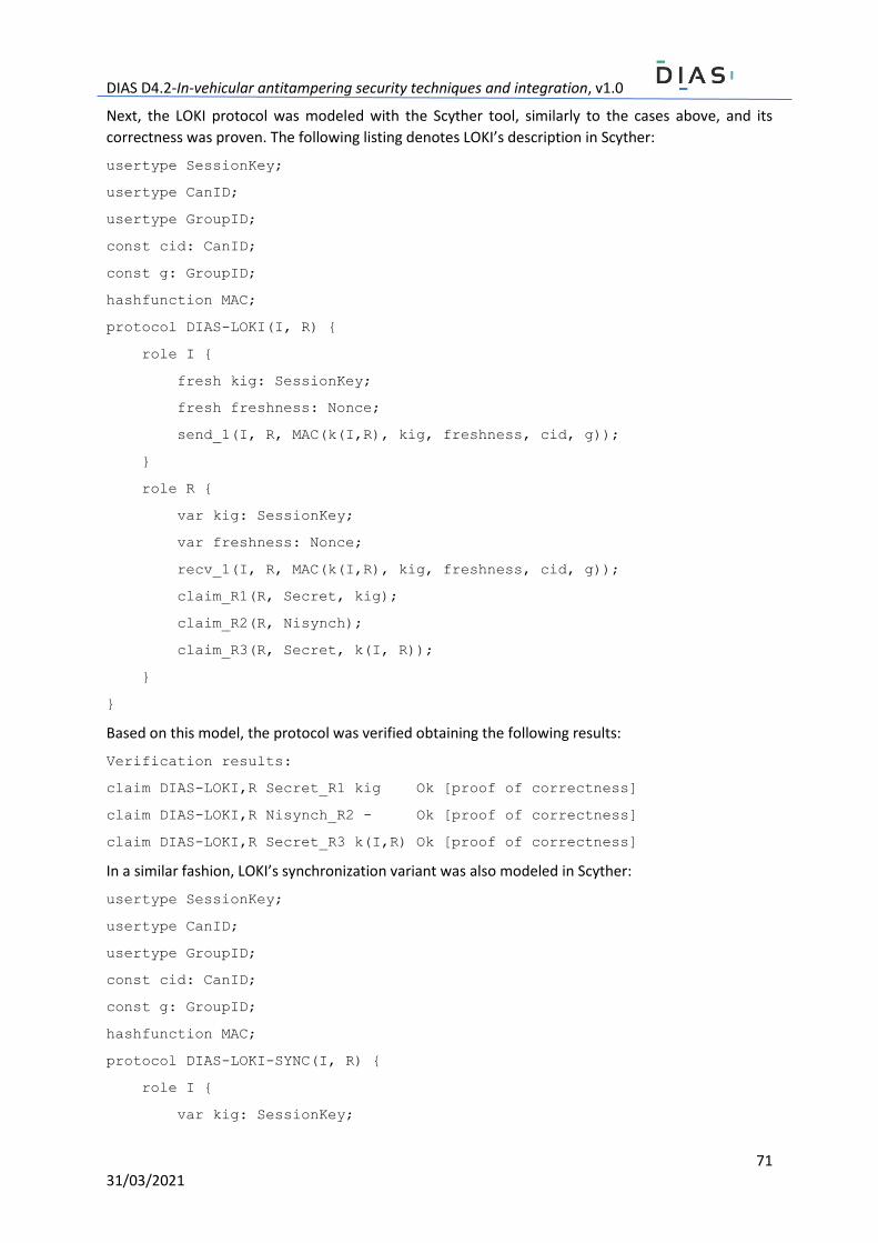
DIAS D4.2-In-vehicular antitampering security techniques and integration, v1.0
71 31/03/2021
Next, the LOKI protocol was modeled with the Scyther tool, similarly to the cases above, and its
correctness was proven. The following listing denotes LOKI’s description in Scyther:
usertype SessionKey;
usertype CanID;
usertype GroupID;
const cid: CanID;
const g: GroupID;
hashfunction MAC;
protocol DIAS-LOKI(I, R) {
role I {
fresh kig: SessionKey;
fresh freshness: Nonce;
send_1(I, R, MAC(k(I,R), kig, freshness, cid, g));
}
role R {
var kig: SessionKey;
var freshness: Nonce;
recv_1(I, R, MAC(k(I,R), kig, freshness, cid, g));
claim_R1(R, Secret, kig);
claim_R2(R, Nisynch);
claim_R3(R, Secret, k(I, R));
}
}
Based on this model, the protocol was verified obtaining the following results:
Verification results:
claim DIAS-LOKI,R Secret_R1 kig Ok [proof of correctness]
claim DIAS-LOKI,R Nisynch_R2 - Ok [proof of correctness]
claim DIAS-LOKI,R Secret_R3 k(I,R) Ok [proof of correctness]
In a similar fashion, LOKI’s synchronization variant was also modeled in Scyther:
usertype SessionKey;
usertype CanID;
usertype GroupID;
const cid: CanID;
const g: GroupID;
hashfunction MAC;
protocol DIAS-LOKI-SYNC(I, R) {
role I {
var kig: SessionKey;

DIAS D4.2-In-vehicular antitampering security techniques and integration, v1.0
72 31/03/2021
fresh freshness: Nonce;
fresh n: Nonce;
var ninc: Nonce;
send_1(I, R, n, MAC(k(I, R), n, freshness, cid, g));
recv_2(R, I, {kig}k(I, R), MAC(k(I, R), {kig}k(I, R),
ninc, freshness, cid, g));
claim_I1(I, Secret, k(I, R));
claim_I2(I, Secret, kig);
claim_I3(I, Nisynch);
}
role R {
fresh kig: SessionKey;
var freshness: Nonce;
fresh ninc: Nonce;
var n: Nonce;
recv_1(I, R, n, MAC(k(I, R), n, freshness, cid, g));
send_2(R, I, {kig}k(I, R), MAC(k(I, R), {kig}k(I, R),
ninc, freshness, cid, g));
claim_R1(R, Secret, k(I, R));
claim_R2(R, Secret, kig);
claim_R3(R, Nisynch);
}
}
According to the model above, after running the Scyther tool, the following result was obtained:
Verification results:
claim DIAS-LOKI-SYNC,I Secret_I1 k(I,R) Ok [proof of correctness]
claim DIAS-LOKI-SYNC,I Secret_I2 kig Ok [proof of correctness]
claim DIAS-LOKI-SYNC,I Nisynch_I3 - Ok [proof of correctness]
claim DIAS-LOKI-SYNC,R Secret_R1 k(I,R) Ok [proof of correctness]
claim DIAS-LOKI-SYNC,R Secret_R2 kig Ok [proof of correctness]
claim DIAS-LOKI-SYNC,R Nisynch_R3 - Ok [proof of correctness]
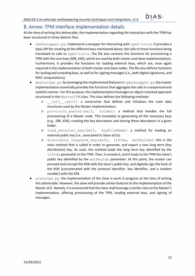
DIAS D4.2-In-vehicular antitampering security techniques and integration, v1.0
73 31/03/2021
B. Annex: TPM interface implementation details At the time of writing this deliverable, the implementation regarding the interaction with the TPM has
been structured in three distinct files:
● tpm2wrapper.py: implements a wrapper for interacting with tpm2-tools. It provides a
basic API for creating all the different keys mentioned above, the calls to these functions being
translated to calls to tpm2-tools. The file also contains the functions for provisioning a
TPM with the core keys (SRK, KSK), which are used by both master and slave implementations.
Furthermore, it provides the functions for loading external keys, which are, once again
required in the implementation of both master and slave nodes. The file also defines functions
for sealing and unsealing keys, as well as for signing messages (i.e., both digital signatures, and
MAC computations).
● mastertpm.py: by leveraging the implemented features in tpm2wrapper.py the master
implementation essentially provides the functions that aggregate the calls in a sequenced and
stateful manner. For this purpose, the implementation leverages an object-oriented approach
structured in the MasterTPM class. The class defines the following methods:
○ __init__(self): a constructor that defines and initializes the main data
structures used by the Master implementation.
○ provision_master(self, folder): a method that handles the full
provisioning of a Master node. This translates to generating all the necessary keys
(e.g., SRK, KSK), creating the key descriptors and storing these descriptors in a given
folder.
○ load_external_key(self, keyFileName): a method for loading an
external public key (i.e., associated to Slave xCUs).
○ distribute_longterm_key(self, ltkIdx, extKeyIdx): this is the
main method that is called in order to generate, and export a new long term (key
distribution) key. As such, the method loads the long term key identified by the
ltkIdx parameter to the TPM. Then, it unseals it, and it loads to the TPM the slave’s
public key identified by the extKeyIdx parameter. At this point, the master can
proceed and encrypt the KDK with the slave’s public key, and digitally sign the hash of
the KDK (concatenated with the protocol identifier, key identifier, and a random
number) with the KSK.
● slavetpm.py: the implementation of the slave is work in progress at the time of writing
this deliverable. However, the slave will provide similar features to the implementation of the
Master xCU. Namely, it is envisioned that the slave shall leverage a similar class to the Master’s
implementation, offering provisioning of the TPM, loading external keys, and signing of
messages.
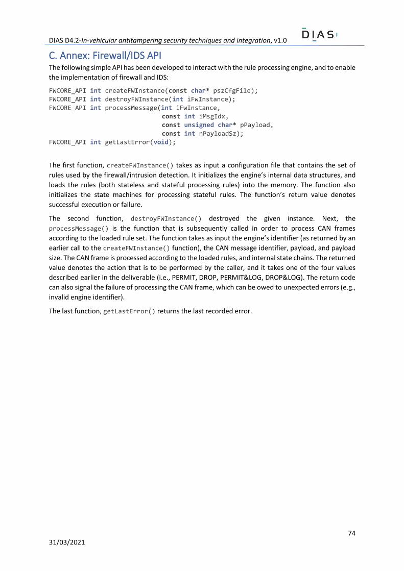
DIAS D4.2-In-vehicular antitampering security techniques and integration, v1.0
74 31/03/2021
C. Annex: Firewall/IDS API The following simple API has been developed to interact with the rule processing engine, and to enable
the implementation of firewall and IDS:
FWCORE_API int createFWInstance(const char* pszCfgFile);
FWCORE_API int destroyFWInstance(int iFwInstance);
FWCORE_API int processMessage(int iFwInstance,
const int iMsgIdx,
const unsigned char* pPayload,
const int nPayloadSz);
FWCORE_API int getLastError(void);
The first function, createFWInstance() takes as input a configuration file that contains the set of
rules used by the firewall/intrusion detection. It initializes the engine’s internal data structures, and
loads the rules (both stateless and stateful processing rules) into the memory. The function also
initializes the state machines for processing stateful rules. The function’s return value denotes
successful execution or failure.
The second function, destroyFWInstance() destroyed the given instance. Next, the
processMessage() is the function that is subsequently called in order to process CAN frames
according to the loaded rule set. The function takes as input the engine’s identifier (as returned by an
earlier call to the createFWInstance() function), the CAN message identifier, payload, and payload
size. The CAN frame is processed according to the loaded rules, and internal state chains. The returned
value denotes the action that is to be performed by the caller, and it takes one of the four values
described earlier in the deliverable (i.e., PERMIT, DROP, PERMIT&LOG, DROP&LOG). The return code
can also signal the failure of processing the CAN frame, which can be owed to unexpected errors (e.g.,
invalid engine identifier).
The last function, getLastError() returns the last recorded error.
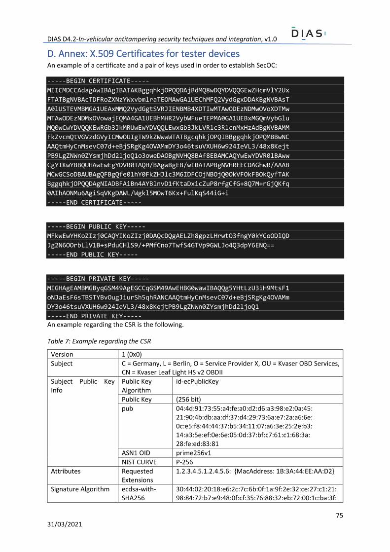
DIAS D4.2-In-vehicular antitampering security techniques and integration, v1.0
75 31/03/2021
D. Annex: X.509 Certificates for tester devices An example of a certificate and a pair of keys used in order to establish SecOC:
-----BEGIN CERTIFICATE-----
MIICMDCCAdagAwIBAgIBATAKBggqhkjOPQQDAjBdMQ8wDQYDVQQGEwZHcmVlY2Ux
FTATBgNVBAcTDFRoZXNzYWxvbmlraTEOMAwGA1UEChMFQ2VydGgxDDAKBgNVBAsT
A0lUSTEVMBMGA1UEAxMMQ2VydGgtSVRJIENBMB4XDTIwMTAwODEzNDMwOVoXDTMw
MTAwODEzNDMxOVowajEQMA4GA1UEBhMHR2VybWFueTEPMA0GA1UEBxMGQmVybGlu
MQ0wCwYDVQQKEwRGb3JkMRUwEwYDVQQLEwxGb3JkLVRlc3RlcnMxHzAdBgNVBAMM
FkZvcmQtVGVzdGVyICMwOUIgTW9kZWwwWTATBgcqhkjOPQIBBggqhkjOPQMBBwNC
AAQtmHyCnMsevC07d+eBjSRgKg4OVAMmDY3o46tsuVXUH6w924IeVL3/48x8Kejt
PB9LgZNWn0ZYsmjhDd2ljoQ1o3oweDAOBgNVHQ8BAf8EBAMCAQYwEwYDVR0lBAww
CgYIKwYBBQUHAwEwEgYDVR0TAQH/BAgwBgEB/wIBATAPBgNVHREECDAGhwR/AAAB
MCwGCSoDBAUBAgQFBgQfe01hY0FkZHJlc3M6IDFCOjNBOjQ0OkVFOkFBOkQyfTAK
BggqhkjOPQQDAgNIADBFAiBn4AYBlnvD1fKtaDxicZuP8rfgCfG+8Q7M+rGjQKfq
0AIhAONMu6AgiSqVKgDAWL/Wgkl5MOwT6Kx+FulKqS44iG+i
-----END CERTIFICATE-----
-----BEGIN PUBLIC KEY-----
MFkwEwYHKoZIzj0CAQYIKoZIzj0DAQcDQgAELZh8gpzLHrwtO3fngY0kYCoODlQD
Jg2N6OOrbLlV1B+sPduCHlS9/+PMfCno7TwfS4GTVp9GWLJo4Q3dpY6ENQ==
-----END PUBLIC KEY-----
-----BEGIN PRIVATE KEY-----
MIGHAgEAMBMGByqGSM49AgEGCCqGSM49AwEHBG0wawIBAQQg5YHtLzU3iH9MtsF1
oNJaEsF6sTBSTYBvOugJiurSh5qhRANCAAQtmHyCnMsevC07d+eBjSRgKg4OVAMm
DY3o46tsuVXUH6w924IeVL3/48x8KejtPB9LgZNWn0ZYsmjhDd2ljoQ1
-----END PRIVATE KEY----- An example regarding the CSR is the following.
Table 7: Example regarding the CSR
Version 1 (0x0)
Subject C = Germany, L = Berlin, O = Service Provider X, OU = Kvaser OBD Services, CN = Kvaser Leaf Light HS v2 OBDII
Subject Public Key Info
Public Key Algorithm
id-ecPublicKey
Public Key (256 bit)
pub 04:4d:91:73:55:a4:fe:a0:d2:d6:a3:98:e2:0a:45: 21:90:4b:db:aa:df:37:d4:29:73:6a:e7:2a:a6:6e: 0c:e5:f8:44:44:37:b5:34:11:07:a6:3e:25:2e:b3: 14:a3:5e:ef:0e:6e:05:0d:37:bf:c7:61:c1:68:3a: 28:fe:ed:83:81
ASN1 OID prime256v1
NIST CURVE P-256
Attributes Requested Extensions
1.2.3.4.5.1.2.4.5.6: {MacAddress: 1B:3A:44:EE:AA:D2}
Signature Algorithm ecdsa-with-SHA256
30:44:02:20:18:e6:2c:7c:6b:0f:1a:9f:2e:32:ce:27:c1:21: 98:84:72:b7:e9:48:0f:cf:35:76:88:32:eb:72:00:1c:ba:3f:
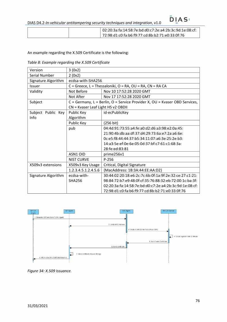
DIAS D4.2-In-vehicular antitampering security techniques and integration, v1.0
76 31/03/2021
02:20:3a:fa:14:58:7e:bd:d0:c7:2e:a4:2b:3c:9d:1e:08:cf: 72:98:d1:c0:fa:b6:f9:77:cd:8b:b2:71:e0:33:0f:76
An example regarding the X.509 Certificate is the following:
Table 8: Example regarding the X.509 Certificate
Version 3 (0x2)
Serial Number 2 (0x2)
Signature Algorithm ecdsa-with-SHA256
Issuer C = Greece, L = Thessaloniki, O = RA, OU = RA, CN = RA CA
Validity Not Before Nov 10 17:52:28 2020 GMT
Not After Nov 17 17:52:28 2020 GMT
Subject C = Germany, L = Berlin, O = Service Provider X, OU = Kvaser OBD Services, CN = Kvaser Leaf Light HS v2 OBDII
Subject Public Key Info
Public Key Algorithm
id-ecPublicKey
Public Key (256 bit)
pub 04:4d:91:73:55:a4:fe:a0:d2:d6:a3:98:e2:0a:45: 21:90:4b:db:aa:df:37:d4:29:73:6a:e7:2a:a6:6e: 0c:e5:f8:44:44:37:b5:34:11:07:a6:3e:25:2e:b3: 14:a3:5e:ef:0e:6e:05:0d:37:bf:c7:61:c1:68:3a: 28:fe:ed:83:81
ASN1 OID prime256v1
NIST CURVE P-256
X509v3 extensions X509v3 Key Usage Critical, Digital Signature
1.2.3.4.5.1.2.4.5.6 {MacAddress: 1B:3A:44:EE:AA:D2}
Signature Algorithm ecdsa-with-SHA256
30:44:02:20:18:e6:2c:7c:6b:0f:1a:9f:2e:32:ce:27:c1:21: 98:84:72:b7:e9:48:0f:cf:35:76:88:32:eb:72:00:1c:ba:3f: 02:20:3a:fa:14:58:7e:bd:d0:c7:2e:a4:2b:3c:9d:1e:08:cf: 72:98:d1:c0:fa:b6:f9:77:cd:8b:b2:71:e0:33:0f:76
Figure 34: X.509 Issuance.
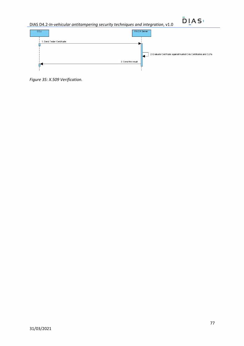
DIAS D4.2-In-vehicular antitampering security techniques and integration, v1.0
77 31/03/2021
Figure 35: X.509 Verification.
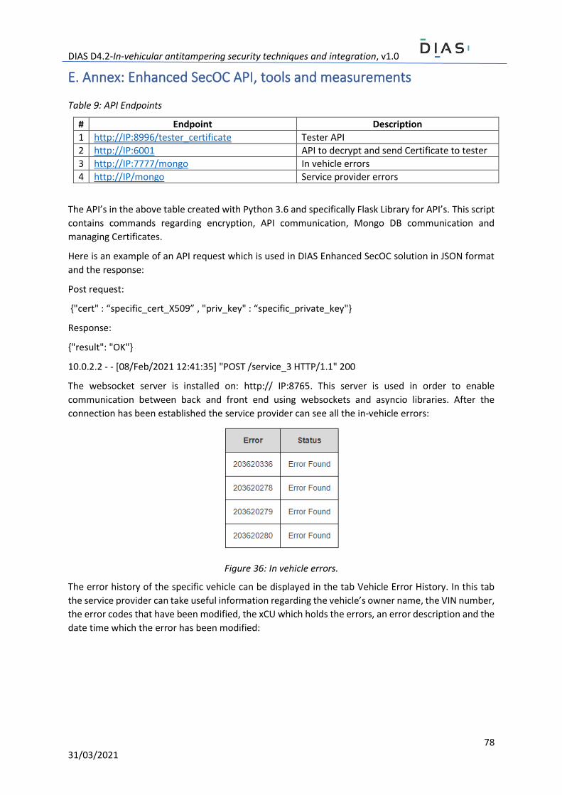
DIAS D4.2-In-vehicular antitampering security techniques and integration, v1.0
78 31/03/2021
E. Annex: Enhanced SecOC API, tools and measurements
Table 9: API Endpoints
# Endpoint Description
1 http://IP:8996/tester_certificate Tester API
2 http://IP:6001 API to decrypt and send Certificate to tester
3 http://IP:7777/mongo In vehicle errors
4 http://IP/mongo Service provider errors
The API’s in the above table created with Python 3.6 and specifically Flask Library for API’s. This script
contains commands regarding encryption, API communication, Mongo DB communication and
managing Certificates.
Here is an example of an API request which is used in DIAS Enhanced SecOC solution in JSON format
and the response:
Post request:
{"cert" : “specific_cert_X509” , "priv_key" : “specific_private_key"}
Response:
{"result": "OK"}
10.0.2.2 - - [08/Feb/2021 12:41:35] "POST /service_3 HTTP/1.1" 200
The websocket server is installed on: http:// IP:8765. This server is used in order to enable
communication between back and front end using websockets and asyncio libraries. After the
connection has been established the service provider can see all the in-vehicle errors:
Figure 36: In vehicle errors.
The error history of the specific vehicle can be displayed in the tab Vehicle Error History. In this tab
the service provider can take useful information regarding the vehicle’s owner name, the VIN number,
the error codes that have been modified, the xCU which holds the errors, an error description and the
date time which the error has been modified:
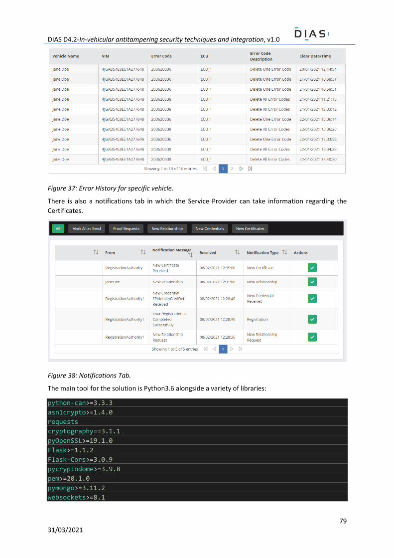
DIAS D4.2-In-vehicular antitampering security techniques and integration, v1.0
79 31/03/2021
Figure 37: Error History for specific vehicle.
There is also a notifications tab in which the Service Provider can take information regarding the
Certificates.
Figure 38: Notifications Tab.
The main tool for the solution is Python3.6 alongside a variety of libraries:
python-can>=3.3.3
asn1crypto>=1.4.0
requests
cryptography==3.1.1
pyOpenSSL>=19.1.0
Flask>=1.1.2
Flask-Cors>=3.0.9
pycryptodome>=3.9.8
pem>=20.1.0
pymongo>=3.11.2
websockets>=8.1
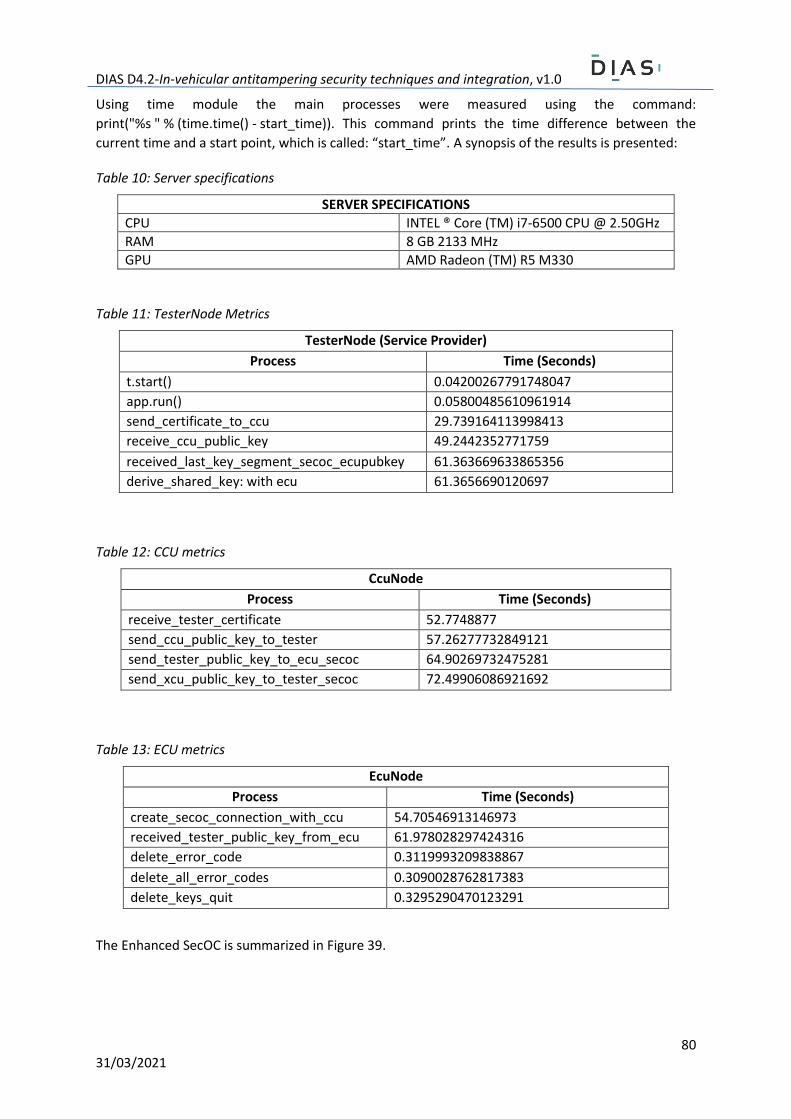
DIAS D4.2-In-vehicular antitampering security techniques and integration, v1.0
80 31/03/2021
Using time module the main processes were measured using the command:
print("%s " % (time.time() - start_time)). This command prints the time difference between the
current time and a start point, which is called: “start_time”. A synopsis of the results is presented:
Table 10: Server specifications
SERVER SPECIFICATIONS
CPU INTEL ® Core (TM) i7-6500 CPU @ 2.50GHz
RAM 8 GB 2133 MHz
GPU AMD Radeon (TM) R5 M330
Table 11: TesterNode Metrics
TesterNode (Service Provider)
Process Time (Seconds)
t.start() 0.04200267791748047
app.run() 0.05800485610961914
send_certificate_to_ccu 29.739164113998413
receive_ccu_public_key 49.2442352771759
received_last_key_segment_secoc_ecupubkey 61.363669633865356
derive_shared_key: with ecu 61.3656690120697
Table 12: CCU metrics
CcuNode
Process Time (Seconds)
receive_tester_certificate 52.7748877
send_ccu_public_key_to_tester 57.26277732849121
send_tester_public_key_to_ecu_secoc 64.90269732475281
send_xcu_public_key_to_tester_secoc 72.49906086921692
Table 13: ECU metrics
EcuNode
Process Time (Seconds)
create_secoc_connection_with_ccu 54.70546913146973
received_tester_public_key_from_ecu 61.978028297424316
delete_error_code 0.3119993209838867
delete_all_error_codes 0.3090028762817383
delete_keys_quit 0.3295290470123291
The Enhanced SecOC is summarized in Figure 39.
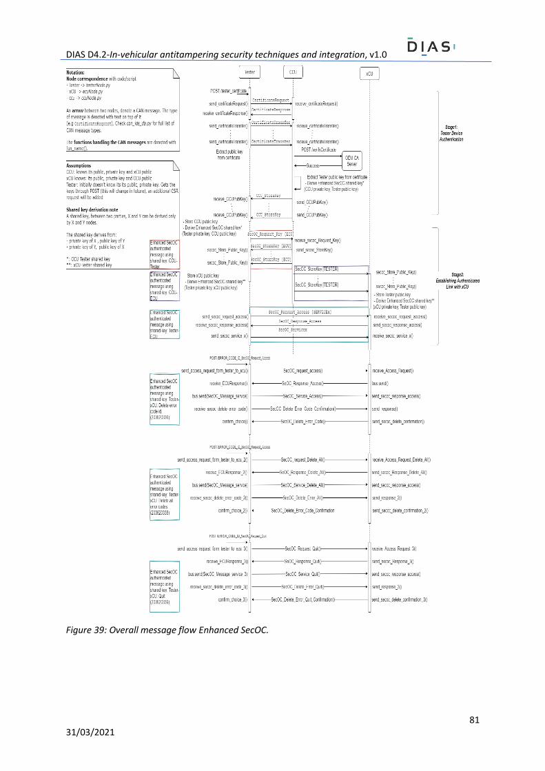
DIAS D4.2-In-vehicular antitampering security techniques and integration, v1.0
81 31/03/2021
Figure 39: Overall message flow Enhanced SecOC.