dhanalakshmi college of engineering … · 1. to acquire practical knowledge on handling basic...
TRANSCRIPT
DHANALAKSHMI COLLEGE OF ENGINEERING Tambaram, Chennai –601 301
DEPARTMENT OF CIVIL ENGINEERING
CE8361 – SURVEYING LABORATORY
III SEMESTER - R 2017
Name :
Register No. :
Class :
LABORATORY MANUAL

Format No. :DCE/Stud/LP/34/Issue : 00/Revision : 00
MISSION
DHANALAKSHMI COLLEGE OF ENGINEERING
Dhanalakshmi College of Engineering is committed to provide highly disciplined, conscientious
and enterprising professionals conforming to global standards through value based quality education
and training.
To provide competent technical manpower capable of meeting requirements of the industry
To contribute to the promotion of academic excellence in pursuit of technical education at
different levels
To train the students to sell his brawn and brain to the highest bidder but to never put a price tag
on heart and soul
DEPARTMENT OF CIVIL ENGINEERING
To impart professional education integrated with human values to the younger generation, so
as to shape them as proficient and dedicated engineers, capable of providing comprehensive
solutions to the challenges in deploying technology for the service of humanity
To educate the students with the state-of-art technologies to meet the growing challenges of the
civil industry
To carry out research through continuous interaction with research institutes and industry, on
advances in structural systems
To provide the students with strong ground rules to facilitate them for systematic learning,
innovation and ethical practice
VISION
VISION
MISSION

Format No. :DCE/Stud/LP/34/Issue : 00/Revision : 00
PROGRAMME EDUCATIONAL OBJECTIVES (PEOs)
1. FUNDAMENTALS
To provide students with a solid foundation in Mathematics, Science and fundamentals of
engineering, enabling them to apply, to find solutions for engineering problems and use this
knowledge to acquire higher education
2. CORE COMPETENCE
To train the students in Civil Engineering technologies so that they apply their knowledge and
training to compare, and to analyze various engineering industrial problems to find solutions
3. BREADTH
To provide relevant training and experience to bridge the gap between theories and practice this
enables them to find solutions for the real time problems in industry, and to design products
4. PROFESSIONALISM
To inculcate professional and effective communication skills, leadership qualities and team
spirit in the students to make them multi-faceted personalities and develop their ability to relate
engineering issues to broader social context
5. LIFELONG LEARNING/ETHICS
To demonstrate and practice ethical and professional responsibilities in the industry and society
in the large, through commitment and lifelong learning needed for successful professional career

Format No. :DCE/Stud/LP/34/Issue : 00/Revision : 00
PROGRAMME OUTCOMES (POs)
a) To demonstrate and apply knowledge of Mathematics, Science and engineering fundamentals
in Civil Engineering field
b) To design a component, a system or a process to meet the specific needs within the realistic
constraints such as economics, environment, ethics, health, safety and manufacturability
c) To demonstrate the competency to use software tools for analysis and design of structures
d) To identify, constructional errors and solve Civil Engineering problems
e) To demonstrate an ability to visualize and work on laboratory and multidisciplinary tasks
f) To function as a member or a leader in multidisciplinary activities
g) To communicate in verbal and written form with fellow engineers and society at large
h) To understand the impact of Civil Engineering in the society and demonstrate awareness of
contemporary issues and commitment to give solutions exhibiting social responsibility
i) To demonstrate professional & ethical responsibilities
j) To exhibit confidence in self-education and ability for lifelong learning
k) To participate and succeed in competitive exam
Format No. :DCE/Stud/LP/34/Issue : 00/Revision : 00
CE8361 – SURVEYING LABORATORY
SYLLABUS
1. To acquire practical knowledge on handling basic chain survey equipment’s
2. To possess knowledge about compass surveying
3. To have the ability to prepare leveling table
4. To possess knowledge about contour map
5. To possess knowledge about the advanced surveying
LIST OF EXPERIMENTS
1. Study of chains and its accessories, Aligning, Ranging, Chaining and Marking Perpendicular offset
2. Setting out works – Foundation marking using tapes single Room and Double Room
3. Compass Traversing – Measuring Bearings & arriving included angles
4. Fly levelling using Dumpy level &Tilting level
5. Check levelling
6. Measurements of horizontal angles by reiteration and repetition and vertical angles
7. Determination of elevation of an object using single plane method when base is
accessible/inaccessible
8. Determination of Tacheometric Constants
9. Heights and distances by stadia Tacheometry
10. Heights and distances by Tangential Tacheometry
11. Study of Total Station, Measuring Horizontal and vertical angles
12. Determination of distance and difference in elevation between two inaccessible points using Total
station
1. Gain the ability to use modern survey equipment to measure angle and distance
2. Understood the basic principle and techniques about survey field
3. Gain design knowledge related to various structural system
COURSE OBJECTIVES
COURSE OUTCOMES
Format No. :DCE/Stud/LP/34/Issue : 00/Revision : 00
INDEX
Sl. NO. LIST OF EXPERIMENTS Page No.
Cycle 1 - Experiments
1 Study of chains and its accessories, Aligning, Ranging, Chaining and Marking Perpendicular offset
2 Setting out works – Foundation marking using tapes single Room and Double Room
3 Compass Traversing – Measuring Bearings & arriving included angles
4 Fly levelling using Dumpy level &Tilting level
5 Check levelling
6 Measurements of horizontal angles by reiteration and repetition and vertical angles
7 Determination of elevation of an object using single plane method when base is accessible/inaccessible
Cycle 2 – Experiments
8 Determination of Tacheometric Constants
9 Heights and distances by stadia Tacheometry
10 Heights and distances by Tangential Tacheometry
11 Study of Total Station, Measuring Horizontal and vertical angles
Additional Experiments Beyond The Syllabus
12 Plane table surveying – Radiation method
13 Plane table surveying – Intersection method
LIST OF PROJECTS
Format No. :DCE/Stud/LP/34/Issue : 00/Revision : 00
EXPT. NO.1 STUDY OF CHAINS AND ITS ACCESSORIES, ALIGNING, RANGING, CHAINING AND MARKING PERPENDICULAR OFFSET
Aim:
To study the Chain and tape and accessories used for chain surveying
A) Chain: 1. The chains are made in lengths of 30 meters/20 meters.
2. The brass tallies are fixed at every 5m length.
3. Small brass rings are provided at every one meter length.
4. It is composed of 100 or 150 pieces of galvanized mild steel wire of 4mm in diameter called links.
5. The ends of each links are bent into a loop and connected together by means of 3 oval rings which give
flexibility to the chain.
6. The length of each links is 20cm i.e. the distance between 2 consecutive middle rings.
7. The end of the chains is provided with brass handle for dragging the chain on the ground.
8. The chain length is measured from the outside of one handle to the other.
9. To hold the arrows in the position with the handle of the chain a groove is cut on the outside surface of the
handle.
B) Ranging rods:
1. They are usually of 2m or 3m in length.
2. They are in circular cross section and having alternate black, white and red bands of 20 cm length each to
make them visible at a distance.
3. They are used for ranging the lines and for marking the positions of points on the ground.
C) Arrows:
1. They are made of a steel wire of 4mm diameter for 40cm length.
2. They are pointed at one end for inserting into the ground and bent at the other end for facility of carrying.
3. They are used to mark the end of each chain during chaining.
E) Cross staff:
1. It consists of a wooden block with two fine sow cuts at right angles to each other on the top.
2. It is used to set a perpendicular at a given point on the chain line.
3. The head is fixed to a top of an iron staff with pointed end to drive into the ground.
F) Optical square:
1. This is also used to set a perpendicular with more accuracy.
2. This has 2 mirrors placed at an angle of 45 ۨ to each other.

Format No. :DCE/Stud/LP/34/Issue : 00/Revision : 00
3. By means of reflection we can see the ranging rods along the chain line and the offset point at right angles
to the chain lines simultaneously.
Result:
The Chain and tape and accessories used for chain surveying has been studied fully
Outcome:
At the end of this experiment, student acquires knowledge about the Chain and tape and accessories used for chain
surveying
Format No. :DCE/Stud/LP/34/Issue : 00/Revision : 00
EXPT. NO.2 ALIGNING, RANGING AND CHAINING OF A LINE
Aim:
To find the distance between the given two points by ranging and chaining a line
Apparatus required:
1. Chain (30m)
2. Ranging rods
3. Arrows
Procedure:
A) For ranging a line:
1. Fix the ranging rods vertically at the ends of the given line.
2. To fix the intermediate ranging rod, instruct the other person to stand with a ranging rod at any intermediate
point desired.
3. Stand at about 2m behind the first ranging rod and instruct the other person to adjust the ranging rod in
such a way that the intermediate ranging rod comes in a line with the end rods.
4. Erect the rod vertically and firmly at that point.
5. Repeat steps 2 to 4 to erect other intermediate ranging rods.
B) For chaining a line:
1. Hold one handle of the chain at first ranging rod.
2. Instruct the follower to drag the chain along the given line.
3. Fix the arrows at the end of the chain length.
4. Do the same procedure for the full length of the line.
5. Count any fractions of the chain length at the end of the last ranging rod by using tallies, rings & links
Result:
Length of the given line =
Outcome:
At the end of this experiment, student acquires knowledge about the ranging and chaining of the line

Format No. :DCE/Stud/LP/34/Issue : 00/Revision :
00
EXPT. NO.1 DETERMINE THE AREA OF THE BOUNDARY USING CHAIN SURVEY
Aim:
To find out the area of the given boundary points by perpendicular offset method
Instruments required:
1. Chain (30m)
2. Cross staff
3. Ranging rods
4. Arrows
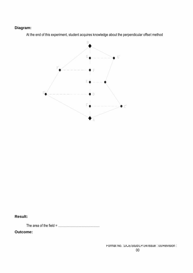
Formulae:
Area of the triangle A = ½ bh sq. units.
Area of the trapezium A = ½ h (a+b) sq. units.
Procedure:
1. The survey stations are fixed.
2. To range a line AB, the ranging rods are fixed at the end of the line.
3. The surveyors stand just behind the ranging rod A. The assistant holds a ranging rod at point C,
approximately on the line AB.
4. Locate the perpendicular offset by using cross staff.
5. Move the cross staff towards left / right.
6. Now base line (AB) is visible and perpendicular line also visible.
7. Perpendicular line measurements are taken.
8. The operation is repeated until the end station of the line is reached.
9. To check the accuracy of the measurement, the line is measured in the reverse direction.
10. Split the area, by triangle and trapezoidal.
11. Move the cross staff towards left / right.
12. Now base line (AB) is visible and perpendicular line also visible.
13. Perpendicular line measurements are taken.
14. Calculate the area by using triangle and trapezoidal formula
Format No. :DCE/Stud/LP/34/Issue : 00/Revision :
00
Diagram:
At the end of this experiment, student acquires knowledge about the perpendicular offset method
Result:
The area of the field = …………………………………
Outcome:

Format No. :DCE/Stud/LP/34/Issue : 00/Revision :
00
1. What is surveying?
2. What are the basic principles of surveying?
3. What is Plane Surveying?
4. What is Geodetic Surveying?
5. What is plumb bob?
6. What is check line and tie line?
7. What is meant by reciprocal ranging?
8. What is meant by hypotenusal allowance?
9. What are optical square?
10. What is well conditioned triangle?
11. What is the use of cross staff?
12. What are all the sources of error?
13. What are the different types of chain triangulation?
14. What is meant by representative fraction?
15. What is meant by scale of plan?
1. Fixing intermediate points on the chain lines, without going to either end we can fix the intermediate
points. Time reducing method
2. Area to be surveyed is comparatively small. It is used for rapid measurements
3. Ranging must be done before a survey line is chained. It may be necessary to establish a number of
intermediate points prior to chaining when chain line is much longer.
4. It is necessary that the chain should be laid out on the ground in a straight line between the end
stations. Error rectifying
Viva-voce
Application
Format No. :DCE/Stud/LP/34/Issue : 00/Revision :
00
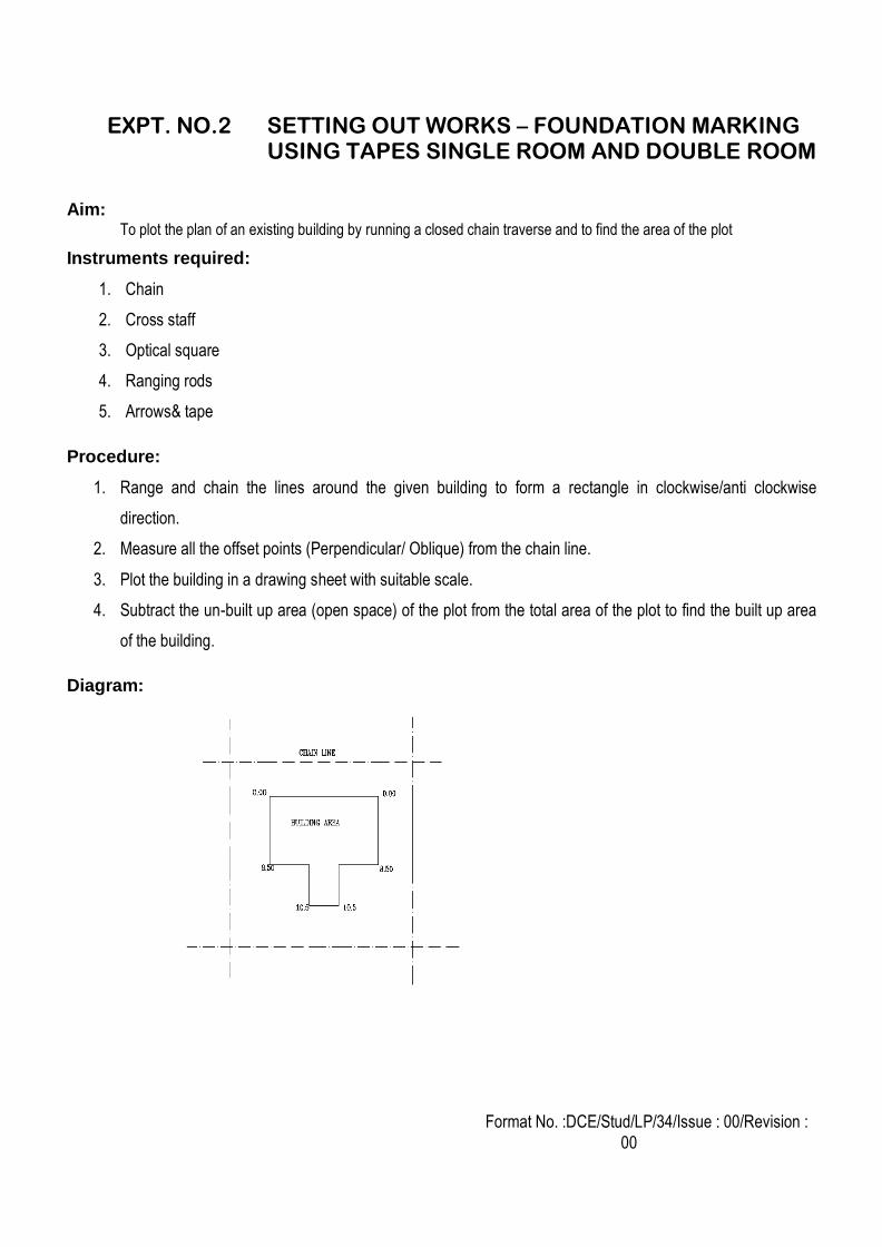
EXPT. NO.2 SETTING OUT WORKS – FOUNDATION MARKING USING TAPES SINGLE ROOM AND DOUBLE ROOM
Aim:
To plot the plan of an existing building by running a closed chain traverse and to find the area of the plot
Instruments required:
1. Chain
2. Cross staff
3. Optical square
4. Ranging rods
5. Arrows& tape
Procedure:
1. Range and chain the lines around the given building to form a rectangle in clockwise/anti clockwise
direction.
2. Measure all the offset points (Perpendicular/ Oblique) from the chain line.
3. Plot the building in a drawing sheet with suitable scale.
4. Subtract the un-built up area (open space) of the plot from the total area of the plot to find the built up area
of the building.
Diagram:

Format No. :DCE/Stud/LP/34/Issue : 00/Revision :
00
Result:
The plan of the building is plotted as shown in figure.
Area of the plot (a) =……………… m2
Area of the open space (b) = ……………… m2
Outcome: Gain knowledge about closed traversing in the wide field
Format No. :DCE/Stud/LP/34/Issue : 00/Revision :
00
1. Mention the different types of chain.
2. Define - ranging.
3. What are the types of ranging?
4. When you adopt reciprocal ranging?
5. What is the length of ranging rod?
6. What are optical square?
7. Define - well conditioned triangle
8. What is the use of cross staff?
9. Mention the sources of error?
10. What are the different types of chain triangulation?
11. What is meant by representative fraction?
12. What is meant by scale of plan?
13. What is meant by well conditional triangle?
14. What is meant by scale in surveying?
15. Define - Plane and Geodetic surveying
1. Ranging must be done before a survey line is chained. It may be necessary to establish a number of
intermediate points prior to chaining when chain line is much longer.
2. Getting accurate values comparing reiteration method. Easy to measure the targets.
3. It is necessary that the chain should be laid out on the ground in a straight line between the end stations.
Viva-voce
Applications
Format No. :DCE/Stud/LP/34/Issue : 00/Revision :
00
EXPT. NO.3 COMPASS TRAVERSING – MEASURING BEARINGS & ARRIVING INCLUDED ANGLES
Aim:
To run a closed compass traverse along a chosen boundary, adjust the closing error by Bowditch rule and calculate the
local attraction
Instruments required:
1. Prismatic Compass
2. Chain or tape
3. Arrows
4. Ranging rods
Procedure:
1. Let A, B, C, D, E be the given points along the closed traverse.
2. Set up the instrument at each point and note down fore bearing and back bearing (i.e) A to B and B to A.
Continue the procedure upto EA and AE.
3. Measure the distances between the consecutive points.
Procedure of balancing a traverse Bowditch’s rule (Graphical method):
1. In figure (a), polygon AB’C’D’E’A’ represents an unbalanced traverse having a closing error equal to A’A
since the first point A and last point A’ are not coinciding.
2. The total closing error AA’ is distributed linearly, to all the sides in proportional to their length by a graphical
construction, shown in figure (b). In figure (b), AB’, B’C’,C’D’, etc. represents the length of the sides of the
traverse, either to the same scale as that of figure (a) or to a reduced scale.
3. The ordinate aA’ is made equal to the closing error A’A of figure (a).
4. By constructing similar triangles, the corresponding errors bB’, cC’, dD’, eE’ are found.
5. In figure (a), lines E’E, D’D, C’C, B’B are drawn parallel to the closing error A’A and made equal to eE’, dD’,
cC’, bB’ respectively.
6. The polygon ABCDE so obtained represents the adjusted traverse.
7. It should be remembered that the ordinates bB’, cC’, dD’, eE’, aA’ of figure (b) represents the corresponding
errors in magnitude only but not in direction.
8. The ordinate aA’ is made equal to the closing error A’A of figure (a).
9. By constructing similar triangles, the corresponding errors bB’, cC’, dD’, eE’ are found.
Format No. :DCE/Stud/LP/34/Issue : 00/Revision :
00
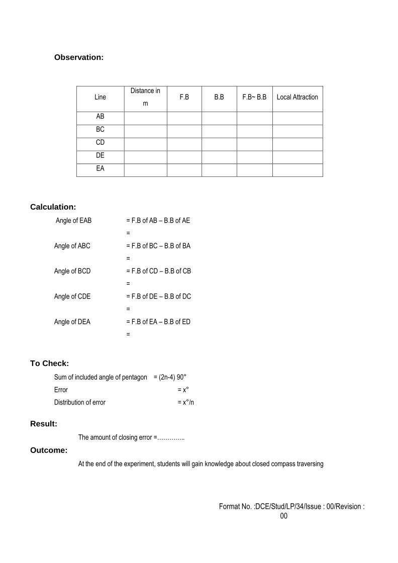
Observation:
Line Distance in
m F.B B.B F.B~ B.B Local Attraction
AB
BC
CD
DE
EA
Calculation:
Angle of EAB = F.B of AB – B.B of AE
=
Angle of ABC = F.B of BC – B.B of BA
=
Angle of BCD = F.B of CD – B.B of CB
=
Angle of CDE = F.B of DE – B.B of DC
=
Angle of DEA = F.B of EA – B.B of ED
=
To Check:
Sum of included angle of pentagon = (2n-4) 90°
Error = x°
Distribution of error = x°/n
Result:
The amount of closing error =…………..
Outcome:
At the end of the experiment, students will gain knowledge about closed compass traversing
Format No. :DCE/Stud/LP/34/Issue : 00/Revision :
00
1. What is local attraction?
2. Define dip
3. What is the least count of compass?
4. What is magnetic declination?
5. How local attraction can be detected?
6. State the two point problem.
7. List out the errors in a plane table surveying.
8. Differentiate closed traverse from open traverse.
9. What is intersection method? Where it is used?
10. What is meant by strength of fix?
11. Write the disadvantages of plane table surveying?
12. Write the advantages of plane table surveying?
13. Differentiate Prismatic compass from Surveyor's compass with reference to reading as well as tripod.
14. List out the errors in a compass instrument.
15. What is true meridian?
1. The compass calculates the bearings in whole circle bearing system which determines the angle which the
survey line makes with the magnetic north in the clockwise direction making good alignment in field work.
2. Compass surveying is recommended when the area is large, undulating and crowded with many details.
3. To find the horizontal angle between the true north and the magnetic north at the time of observation.
Viva-voce
Applications
Format No. :DCE/Stud/LP/34/Issue : 00/Revision :
00
EXPT. NO.4 FLY LEVELLING USING DUMPY LEVEL &TILTING LEVEL
Aim:
To determine the R.L. for the given points and to find the level difference between them
Instruments required:
1. Dumpy level & Tilting level
2. Staff
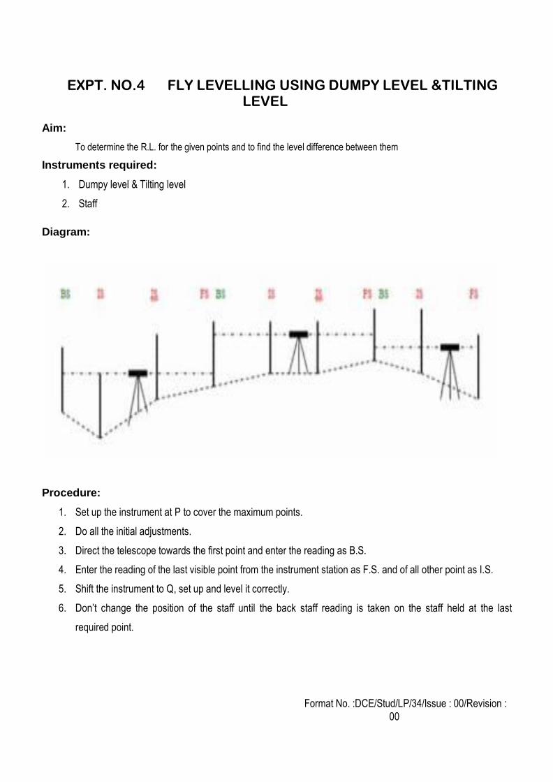
Diagram:
Procedure:
1. Set up the instrument at P to cover the maximum points.
2. Do all the initial adjustments.
3. Direct the telescope towards the first point and enter the reading as B.S.
4. Enter the reading of the last visible point from the instrument station as F.S. and of all other point as I.S.
5. Shift the instrument to Q, set up and level it correctly.
6. Don’t change the position of the staff until the back staff reading is taken on the staff held at the last
required point.
Format No. :DCE/Stud/LP/34/Issue : 00/Revision :
00
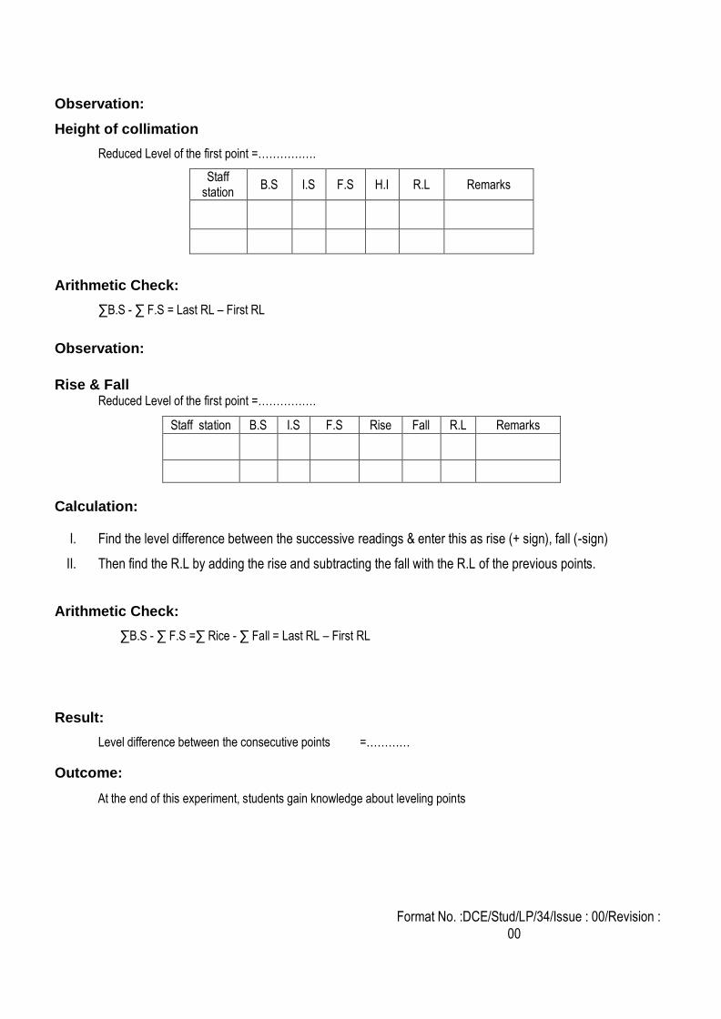
Observation:
Height of collimation
Reduced Level of the first point =…………….
Staff station
B.S I.S F.S H.I R.L Remarks
Arithmetic Check:
∑B.S - ∑ F.S = Last RL – First RL
Observation:
Rise & Fall
Reduced Level of the first point =…………….
Staff station B.S I.S F.S Rise Fall R.L Remarks
Calculation:
I. Find the level difference between the successive readings & enter this as rise (+ sign), fall (-sign)
II. Then find the R.L by adding the rise and subtracting the fall with the R.L of the previous points.
Arithmetic Check:
∑B.S - ∑ F.S =∑ Rice - ∑ Fall = Last RL – First RL
Result:
Level difference between the consecutive points =…………
Outcome:
At the end of this experiment, students gain knowledge about leveling points
Format No. :DCE/Stud/LP/34/Issue : 00/Revision :
00
1. Name the different types of Bench marks.
2. What are the different types of leveling staff?
3. Differentiate level line from a horizontal line.
4. Define – Bench Mark
5. Define – GTS Bench Mark and Arbitrary Bench Mark
6. What are the differences between the line of collimation and the axis of the telescope?
7. How is leveling done using foot screws?
8. What are the errors in leveling?
9. What are the various methods of booking a reduced level?
10. What is fore sight?
11. Compare the rise and fall method and height of collimation method.
12. What is back sight?
13. What is leveling?
14. How leveling is done using foot screws?
15. What is fly leveling?
1. The measured levels can be represented on paper with suitable scale.
2. The existing soil profile at ground level along a particular line, or as related to the proposed surface
of a road or section of a pipeline.
3. Laying a circular arch line for athletics. Reference a circular arch line for taken by this method.
Viva-voce
Applications
Format No. :DCE/Stud/LP/34/Issue : 00/Revision :
00
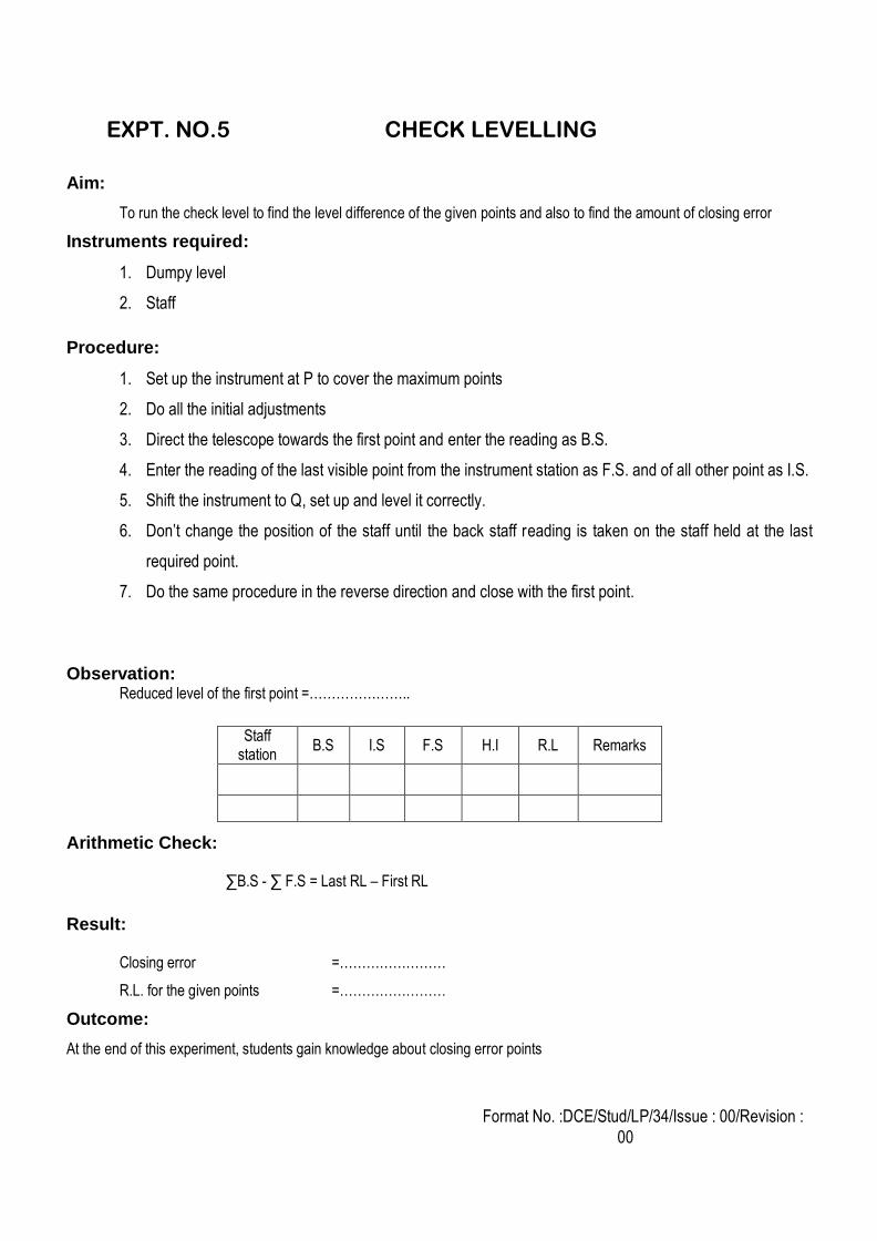
EXPT. NO.5 CHECK LEVELLING
Aim:
To run the check level to find the level difference of the given points and also to find the amount of closing error
Instruments required:
1. Dumpy level
2. Staff
Procedure:
1. Set up the instrument at P to cover the maximum points
2. Do all the initial adjustments
3. Direct the telescope towards the first point and enter the reading as B.S.
4. Enter the reading of the last visible point from the instrument station as F.S. and of all other point as I.S.
5. Shift the instrument to Q, set up and level it correctly.
6. Don’t change the position of the staff until the back staff reading is taken on the staff held at the last
required point.
7. Do the same procedure in the reverse direction and close with the first point.
Observation: Reduced level of the first point =…………………..
Arithmetic Check: ∑B.S - ∑ F.S = Last RL – First RL
Result: Closing error =……………………
R.L. for the given points =……………………
Outcome:
At the end of this experiment, students gain knowledge about closing error points
Staff station
B.S I.S F.S H.I R.L Remarks
Format No. :DCE/Stud/LP/34/Issue : 00/Revision :
00
1. Mention the temporary adjustments of leveling.
2. Define level book.
3. What is mean sea level?
4. How can you calculate object height?
5. What is height of instrument method?
6. Name the different types of Bench marks.
7. What are the different types of leveling staff?
8. Differentiate level line from a horizontal line.
9. Define – Bench Mark
10. Define – GTS Bench Mark and Arbitrary Bench Mark
11. What are the differences between the line of collimation and the axis of the telescope?
12. How is leveling done using foot screws?
13. What are the errors in leveling?
14. What are the various methods of booking a reduced level?
15. What is fore sight?
1. The measured levels can be represented on paper with suitable scale.
2. The existing soil profile at ground level along a particular line, or as related to the proposed surface
of a road or section of a pipeline.
3. Laying a circular arch line for athletics. Reference a circular arch line for taken by this method
Viva-voce
Applications
Format No. :DCE/Stud/LP/34/Issue : 00/Revision :
00
EXPT. NO.6 MEASUREMENTS OF HORIZONTAL ANGLES BY REITERATION ANDREPETITION AND VERTICAL
ANGLES
REPETITION METHOD
Aim:
To find out the horizontal angle between A and B
Instruments required:
1. Theodolite
2. Tape
3. Ranging rods
4. Arrows
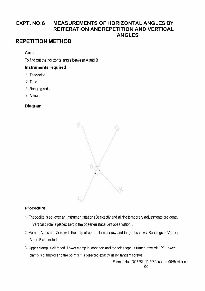
Diagram:
Procedure:
1. Theodolite is set over an instrument station (O) exactly and all the temporary adjustments are done.
Vertical circle is placed Left to the observer (face Left observation).
2. Vernier A is set to Zero with the help of upper clamp screw and tangent screws. Readings of Vernier
A and B are noted.
3. Upper clamp is clamped. Lower clamp is loosened and the telescope is turned towards “P”. Lower
clamp is clamped and the point “P” is bisected exactly using tangent screws.
Format No. :DCE/Stud/LP/34/Issue : 00/Revision :
00
4. Both the vernier A and B are read and noted (Must be equal to 0° and 180° respectively).Upper
clamp is unclamped and the telescope is turned clockwise and “Q” is bisected.
5. Upper clamp is clamped and “Q” is bisected exactly using tangent screws. Both the vernier are read.
Mean of the readings provide an approximate included angle of POQ.
6. The reading of vernier A gives directly the angle POQ, and 180° is subtracted by the reading of
vernier B. The mean value of two readings gives the angle POQ with one face.
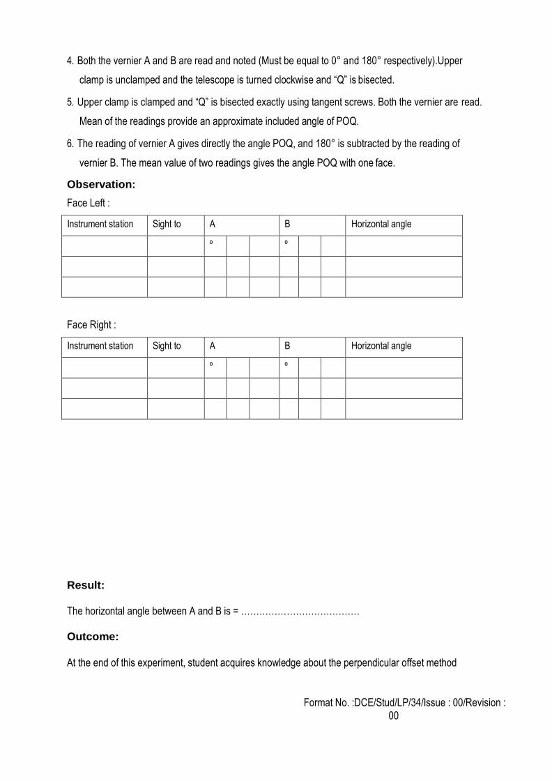
Observation:
Face Left :
Instrument station Sight to A B Horizontal angle
º º
Face Right :
Instrument station Sight to A B Horizontal angle
º º
Result:
The horizontal angle between A and B is = …………………………………
Outcome:
At the end of this experiment, student acquires knowledge about the perpendicular offset method
Format No. :DCE/Stud/LP/34/Issue : 00/Revision :
00
REITERATION METHOD Aim:
To find out the horizontal angle between A and B
Instruments required:
1. Theodolite
2. Tape
3. Ranging rods
4. Arrows
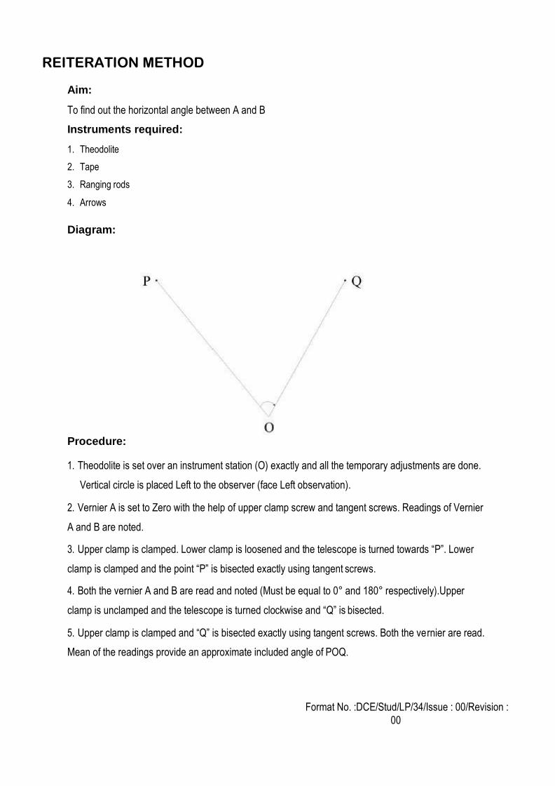
Diagram:
Procedure:
1. Theodolite is set over an instrument station (O) exactly and all the temporary adjustments are done.
Vertical circle is placed Left to the observer (face Left observation).
2. Vernier A is set to Zero with the help of upper clamp screw and tangent screws. Readings of Vernier
A and B are noted.
3. Upper clamp is clamped. Lower clamp is loosened and the telescope is turned towards “P”. Lower
clamp is clamped and the point “P” is bisected exactly using tangent screws.
4. Both the vernier A and B are read and noted (Must be equal to 0° and 180° respectively).Upper
clamp is unclamped and the telescope is turned clockwise and “Q” is bisected.
5. Upper clamp is clamped and “Q” is bisected exactly using tangent screws. Both the vernier are read.
Mean of the readings provide an approximate included angle of POQ.
Format No. :DCE/Stud/LP/34/Issue : 00/Revision :
00
6. The reading of vernier A gives directly the angle POQ, and 180° is subtracted by the reading of
vernier B. The mean value of two readings gives the angle POQ with one face.
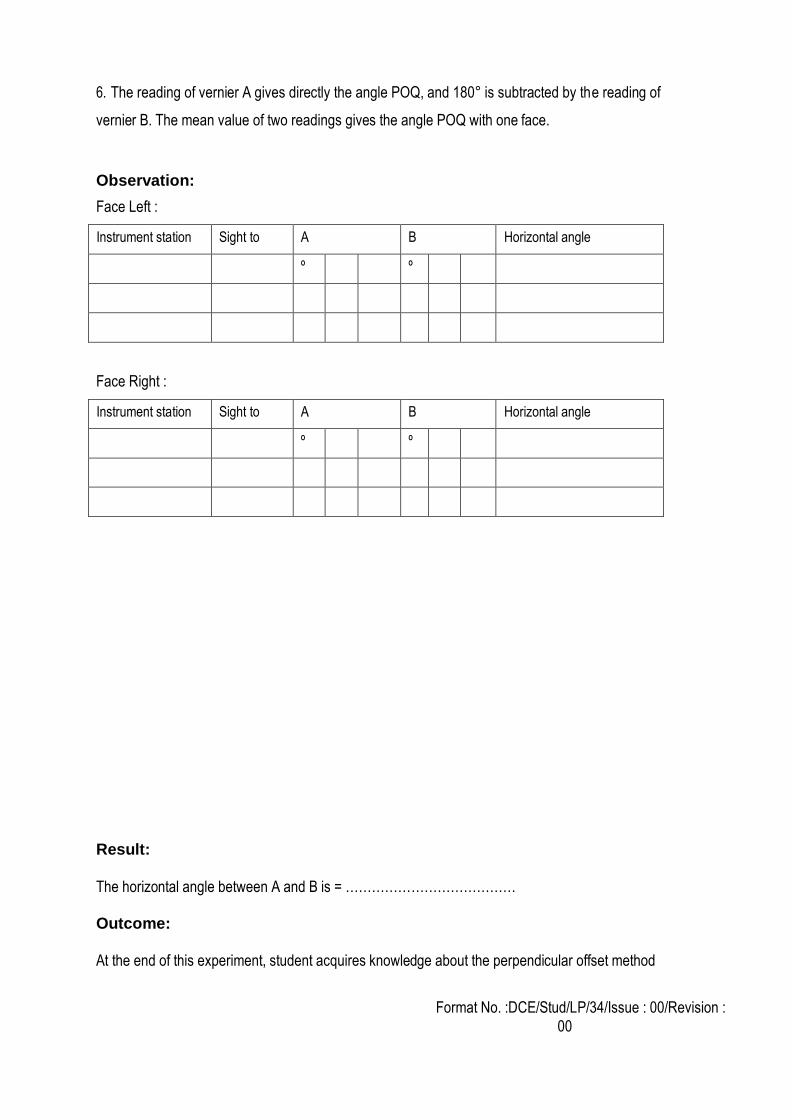
Observation:
Face Left :
Instrument station Sight to A B Horizontal angle
º º
Face Right :
Instrument station Sight to A B Horizontal angle
º º
Result:
The horizontal angle between A and B is = …………………………………
Outcome:
At the end of this experiment, student acquires knowledge about the perpendicular offset method
Format No. :DCE/Stud/LP/34/Issue : 00/Revision :
00
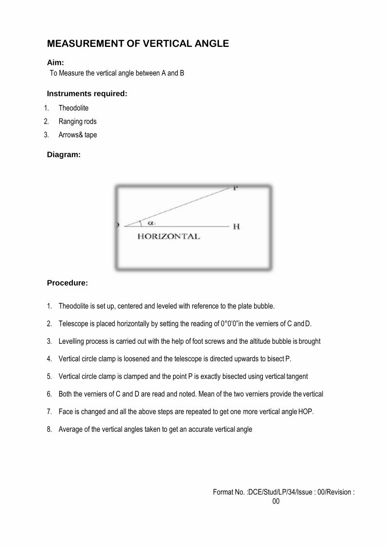
MEASUREMENT OF VERTICAL ANGLE Aim:
To Measure the vertical angle between A and B
Instruments required:
1. Theodolite
2. Ranging rods
3. Arrows& tape
Diagram:
Procedure:
1. Theodolite is set up, centered and leveled with reference to the plate bubble.
2. Telescope is placed horizontally by setting the reading of 0°0’0”in the verniers of C and D.
3. Levelling process is carried out with the help of foot screws and the altitude bubble is brought
4. Vertical circle clamp is loosened and the telescope is directed upwards to bisect P.
5. Vertical circle clamp is clamped and the point P is exactly bisected using vertical tangent
6. Both the verniers of C and D are read and noted. Mean of the two verniers provide the vertical
7. Face is changed and all the above steps are repeated to get one more vertical angle HOP.
8. Average of the vertical angles taken to get an accurate vertical angle
Format No. :DCE/Stud/LP/34/Issue : 00/Revision :
00
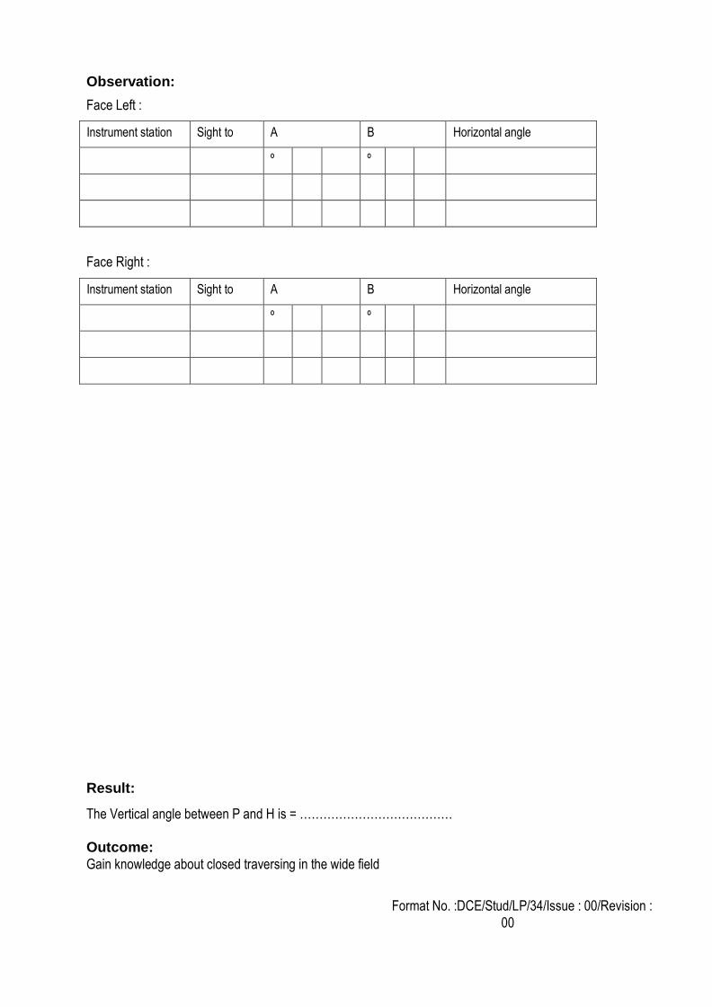
Observation:
Face Left :
Instrument station Sight to A B Horizontal angle
º º
Face Right :
Instrument station Sight to A B Horizontal angle
º º
Result:
The Vertical angle between P and H is = …………………………………
Outcome:
Gain knowledge about closed traversing in the wide field
Format No. :DCE/Stud/LP/34/Issue : 00/Revision :
00
1. What is meant by optical square?
2. What is meant by well-conditioned triangle?
3. What is the use of cross staff?
4. What are all the sources of error?
5. What are the different types of chain triangulation?
6. What is meant by representative fraction?
7. What is meant by scale of plan?
8. What is meant by well conditional triangle?
9. What is meant by scale in surveying?
10. What is plane and geodetic surveying?
11. What is the use of arrows?
12. What is the use of plumb bob?
13. How will you differentiate check line and tie line?
14. What is meant by reciprocal ranging?
15. What is meant by hypotenusual allowance?
1. Getting accurate values comparing reiteration method
2. Easy to measure the targets
3. Error rectifying
Viva-voce
Application
Format No. :DCE/Stud/LP/34/Issue : 00/Revision :
00
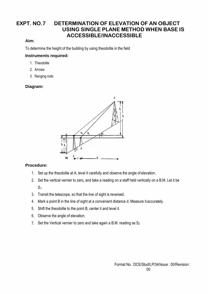
EXPT. NO.7 DETERMINATION OF ELEVATION OF AN OBJECT USING SINGLE PLANE METHOD WHEN BASE IS
ACCESSIBLE/INACCESSIBLE Aim:
To determine the height of the building by using theodolite in the field
Instruments required:
1. Theodolite
2. Arrows
3. Ranging rods
Diagram:
Procedure:
1. Set up the theodolite at A, level it carefully and observe the angle of elevation.
2. Set the vertical vernier to zero, and take a reading on a staff held vertically on a B.M. Let it be
S1.
3. Transit the telescope, so that the line of sight is reversed.
4. Mark a point B in the line of sight at a convenient distance d. Measure it accurately.
5. Shift the theodolite to the point B, center it and level it.
6. Observe the angle of elevation.
7. Set the Vertical vernier to zero and take again a B.M. reading as S2
Format No. :DCE/Stud/LP/34/Issue : 00/Revision :
00
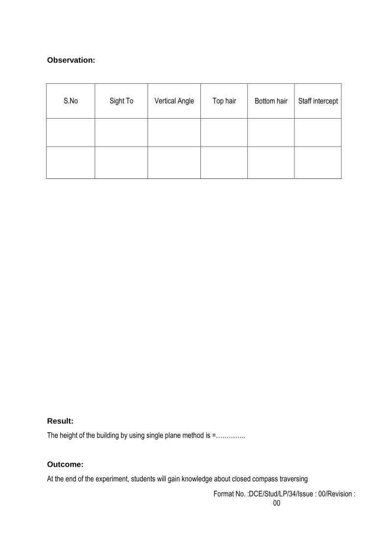
Observation:
S.No
Sight To
Vertical Angle
Top hair
Bottom hair
Staff intercept
Result:
The height of the building by using single plane method is =…………..
Outcome:
At the end of the experiment, students will gain knowledge about closed compass traversing
Format No. :DCE/Stud/LP/34/Issue : 00/Revision :
00
1. What is meant by local attraction?
2. Define – Dip
3. What is the least count of compass?
4. What is meant by magnetic declination?
5. How local attraction can be detected?
6. State the two point problem.
7. List out the errors in a plane table surveying.
8. Differentiate closed traverse from open traverse.
9. What is intersection method? Where it is used?
10. What is meant by strength of fix?
11. Write the disadvantages of plane table surveying.
12. Write the advantages of plane table surveying.
13. Differentiate Prismatic compass from Surveyor's compass with reference to reading as well as tripod.
14. List out the errors in a compass instrument.
15. What is meant by true meridian?
1. Using to measure the height of the different elevation of the structure
2. Reference bench mark is easily taken by this method
3. Getting the elevation value even obstruction in the field
Viva - voce
Application
Format No. :DCE/Stud/LP/34/Issue : 00/Revision :
00
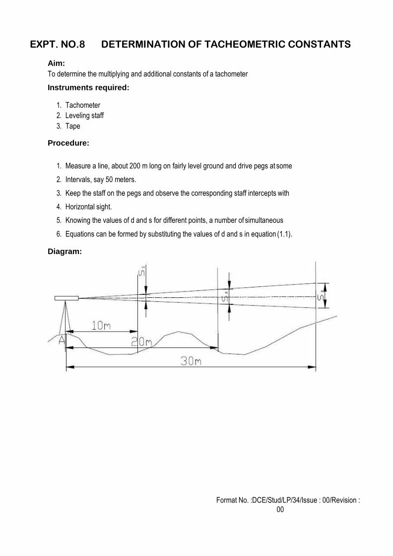
EXPT. NO.8 DETERMINATION OF TACHEOMETRIC CONSTANTS
Aim:
To determine the multiplying and additional constants of a tachometer
Instruments required:
1. Tachometer
2. Leveling staff
3. Tape
Procedure:
1. Measure a line, about 200 m long on fairly level ground and drive pegs at some
2. Intervals, say 50 meters.
3. Keep the staff on the pegs and observe the corresponding staff intercepts with
4. Horizontal sight.
5. Knowing the values of d and s for different points, a number of simultaneous
6. Equations can be formed by substituting the values of d and s in equation (1.1).
Diagram:
Format No. :DCE/Stud/LP/34/Issue : 00/Revision :
00
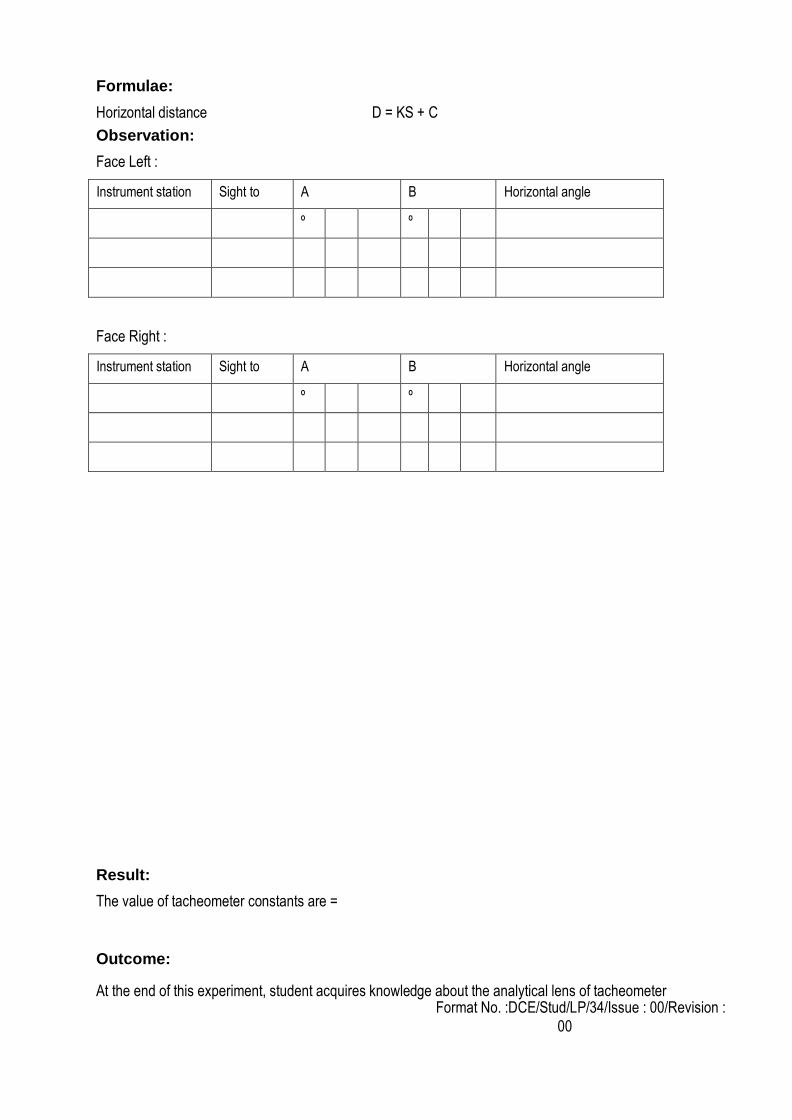
Formulae:
Horizontal distance D = KS + C
Observation:
Face Left :
Instrument station Sight to A B Horizontal angle
º º
Face Right :
Instrument station Sight to A B Horizontal angle
º º
Result:
The value of tacheometer constants are =
Outcome:
At the end of this experiment, student acquires knowledge about the analytical lens of tacheometer
Format No. :DCE/Stud/LP/34/Issue : 00/Revision :
00
1. What is meant by plumb bob?
2. Differentiate between check line and tie line?
3. What is meant by reciprocal ranging?
4. What is meant by hypotenusal allowance?
5. What do you understand by “working from whole to part”?
6. What are the kinds of errors?
7. How will you classify surveying based on accuracy?
8. What are all the types of chain?
9. What are tie stations?
10. What are all the accessories used in chain surveying?
11. What are the errors in chaining?
12. What are the types of Ranging?
13. What is meant by cross staff?
14. What are the types of optical square?
15. What is well conditioned triangle
1. It is used for rapid measurements
2. Knowing the concept of analytical lens in tacheometer
3. Error rectifying
4. Knowing the values of d and s for different points
Viva-voce
Application
Format No. :DCE/Stud/LP/34/Issue : 00/Revision :
00
EXPT. NO.9 HEIGHTS AND DISTANCES BY STADIA TACHEOMETRY
Aim:
To determine the distance and elevation of a point using tacheometric stadia system
Instruments required:
1. Tacheometer
2. Levelling staff
3. Pegs or Arrow
Diagram:
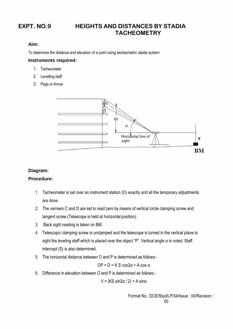
Procedure:
1. Tacheometer is set over an instrument station (O) exactly and all the temporary adjustments
are done.
2. The verniers C and D are set to read zero by means of vertical circle clamping screw and
tangent screw.(Telescope is held at horizontal position).
3. Back sight reading is taken on BM.
4. Telescopic clamping screw is unclamped and the telescope is turned in the vertical plane to
sight the leveling staff which is placed over the object “P”. Vertical angle α is noted. Staff
intercept (S) is also determined.
5. The horizontal distance between O and P is determined as follows:-
OP = D = K S cos2α + A cos α
6. Difference in elevation between O and P is determined as follows:-
V = (KS sin2α / 2) + A sinα
Format No. :DCE/Stud/LP/34/Issue : 00/Revision :
00
7. R.L of point “P” is determined as follows:
R.L of point “P” = R.L of Line of collimation + V- h
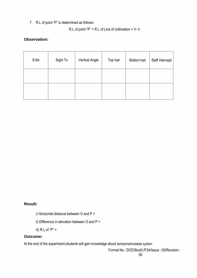
Observation:
S.No
Sight To
Vertical Angle
Top hair
Bottom hair
Staff intercept
Result:
i) Horizontal distance between O and P =
ii) Difference in elevation between O and P =
iii) R.L of “P” =
Outcome:
At the end of the experiment,students will gain knowledge about tacheometricstadia system
Format No. :DCE/Stud/LP/34/Issue : 00/Revision :
00
1. What is the optical square?
2. What is well conditioned triangle?
3. What is the use of cross staff?
4. What are all the sources of error?
5. What are the different types of chain triangulation?
6. What is meant by representative fraction?
7. What is meant by scale of plan?
8. What is meant by well conditional triangle?
9. What is meant by scale in surveying?
10. What is Plane and Geodetic surveying?
11. State the two point problem.
12. List out the errors in a plane table surveying.
13. Differentiate closed traverse from open traverse.
14. What is intersection method? Where it is used?
15. What is meant by strength of fix?
16. Write the disadvantages of plane table surveying.
17. Write the advantages of plane table surveying.
18. Differentiate Prismatic compass from Surveyor's compass with reference to reading as well as tripod.
19. List out the errors in a compass instrument.
20. What is meant by true meridian?
1. Using to measure the height of the different elevation of the structure
2. Reference bench mark is easily taken by this method
3. Getting the elevation value by using stadia hairs
Viva-voce
Application
Format No. :DCE/Stud/LP/34/Issue : 00/Revision :
00
EXPT. NO.10 HEIGHTS AND DISTANCES BY TANGENTIAL TACHEOMETRY
Aim:
To determine the distance and elevation of a point using tangential tacheometric system
Instruments required:
1. Tacheometer
2. Levelling staff
3. Pegs or Arrow
Procedure:
1. Tacheometer is set over an instrument station (O) exactly and all the temporary
adjustments are done.
2. The verniers C and D are set to read zero by means of vertical circle clamping screw and
tangent screw.(Telescope is held at horizontal position).
3. Back sight reading is taken on BM.
4. Telescopic clamping screw is unclamped and the telescope is turned in the vertical plane
to sight the leveling staff which is placed over the object “Q”.
5. Upper target reading (R1) is bisected exactly with the help of telescope clamping screw
and its tangential screw. Vertical angle α1 is noted.
6. Similarly the lower target reading (R2) is bisected and Vertical angle α2 is noted.
7. From the geometry of the figure, difference in elevation are determined as follows:-
MN = D tan α1
M B= D tan α2
8. Telescopic clamping screw is unclamped and the telescope is turned in the vertical
plane to sight the leveling staff which is placed over the object “Q”.
9. Upper target reading (R1) is bisected exactly with the help of telescope clamping screw
and its tangential screw. Vertical angle α1 is noted.
Format No. :DCE/Stud/LP/34/Issue : 00/Revision :
00
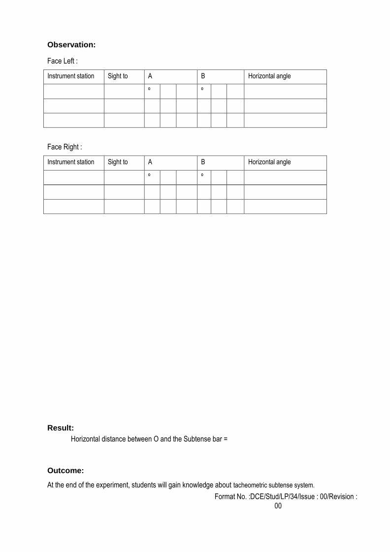
Observation:
Face Left :
Instrument station Sight to A B Horizontal angle
º º
Face Right :
Instrument station Sight to A B Horizontal angle
º º
Result:
Horizontal distance between O and the Subtense bar =
Outcome:
At the end of the experiment, students will gain knowledge about tacheometric subtense system.
Format No. :DCE/Stud/LP/34/Issue : 00/Revision :
00
1. What is meant by tangential method?
2. What are the three cases of vertical angle?
3. Write the formula for both angles are angles of elevation.
4. Write the formula for both angles are angles of depression.
5. Write the formula for one angle elevation and other angle depression.
6. What is meant by special device fitted to tacheometer?
7. What are the errors in stadia surveying?
8. What are the special instruments available to conduct survey?
9. What is the use pendulum level?
10. What is meant by Brunton universal pocket transit?
11. What are all the types of compass used?
12. What is meant by representative fraction?
13. Write the formula for distance and elevation formula for staff normal.
14. What is meant by anallactic lens?
15. State the principle of stadia method.
1. Using to measure the height of the different elevation of the structure
2. Reference bench mark is easily taken by this method
3. Getting the elevation value by using stadia hairs
Viva-voce
Application
Format No. :DCE/Stud/LP/34/Issue : 00/Revision :
00
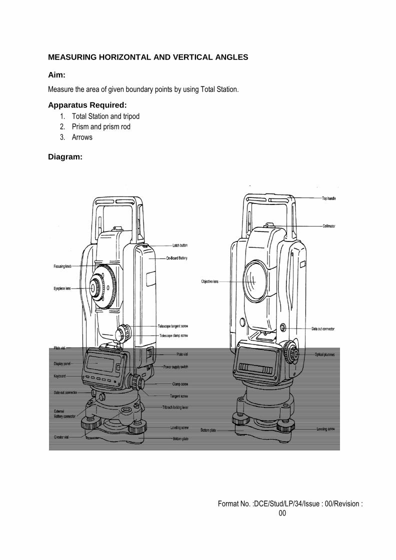
EXPT. NO.11 STUDY OF TOTAL STATION, MEASURING HORIZONTAL AND VERTICAL ANGLES
Aim: To study the total station used for surveying.
Total station:
1. The Total station is designed for measuring of slant distances, horizontal and vertical angles and elevations
in topographic and geodetic works, tachometric surveys, as well as for solution of application geodetic tasks. The measurement results can be recorded into the internal memory and transferred to a personal computer interface.
2. The basic properties are unsurpassed range, speed and accuracy of measurements. Total stations are
developed in view of the maximal convenience of work of the user. High-efficiency electronic tachometers are intended for the decision.
3. Angles and distances are measured from the total station to points under survey, and the coordinates (X, Y,
and Z or northing, easting and elevation) of surveyed points relative to the total station position are calculated using trigonometry and triangulation.
4. Data can be downloaded from the total station to a computer and application software used to compute
results and generate a map of the surveyed area.
5. A total station is an electronic/optical instrument used in modern surveying. It is also used by archaeologists to record excavations as well as by police, crime scene investigators, private accident Reconstructionists and insurance companies to take measurements of scenes. The total station is an electronic theodolite (transit) integrated with an electronic distance meter (EDM), plus internal data storage and/or external data collector.
6. The purpose of any survey is to prepare maps, control points formed a basic requirement for the preparation
of these maps.
7. There are several numbers of methods like traverse, triangulation etc., to provide these control points.
8. Whatever the method the provision of control points, includes the measurement of two entities( Distance and Angle).
Format No. :DCE/Stud/LP/34/Issue : 00/Revision :
00
MEASURING HORIZONTAL AND VERTICAL ANGLES
Aim:
Measure the area of given boundary points by using Total Station.
Apparatus Required:
1. Total Station and tripod
2. Prism and prism rod
3. Arrows
Diagram:
Format No. :DCE/Stud/LP/34/Issue : 00/Revision :
00
Procedure:
1. Set the instrument at the station point which the point covers all boundary points.
2. Do the temporary adjustments in the instrument and level it properly.
3. Set the prism height and enter the prism height value in Total Station.
4. Consider all boundary points in closed traverse.
5. Select the area measurement option and bisect the boundary points with the help of prism.
6. Take readings from all boundary points and directly found the area from Total Station.
Result:
The area of the given field = -------------- measured by Total Station.
Outcome:
Gain the ability to use modern survey equipment to measure angle and distance.
Format No.: DCE/Stud/LM/34?Issue : 00/Revision : 00
1. What is meant by contour gradient?
2. What are the classifications of total station?
3. What are the different methods of contouring?
4. What are the LS and CS?
5. What are the parts of total station?
6. What is meant by vertical axis?
7. What is meant by Horizontal axis?
8. What is meant by line of sight / line of collimation?
9. What is meant by axis of level tube?
10. What is meant by centering?
11. What is meant by transiting?
12. What is meant by swinging the telescope?
13. What is meant by telescope normal?
14. What is meant by telescope inverted?
15. What is meant by changing face?
1. Determining accurate coordinates for survey points by simultaneously recording by total station
observations over a known and unknown survey point for at least 20 minutes
2. Surveyors’ GPS receivers can then collect field data and combine it with the CORS data to
calculate positions
3. Getting the elevation value by using stadia hairs
Viva- voce
Application
Format No.: DCE/Stud/LM/34?Issue : 00/Revision : 00
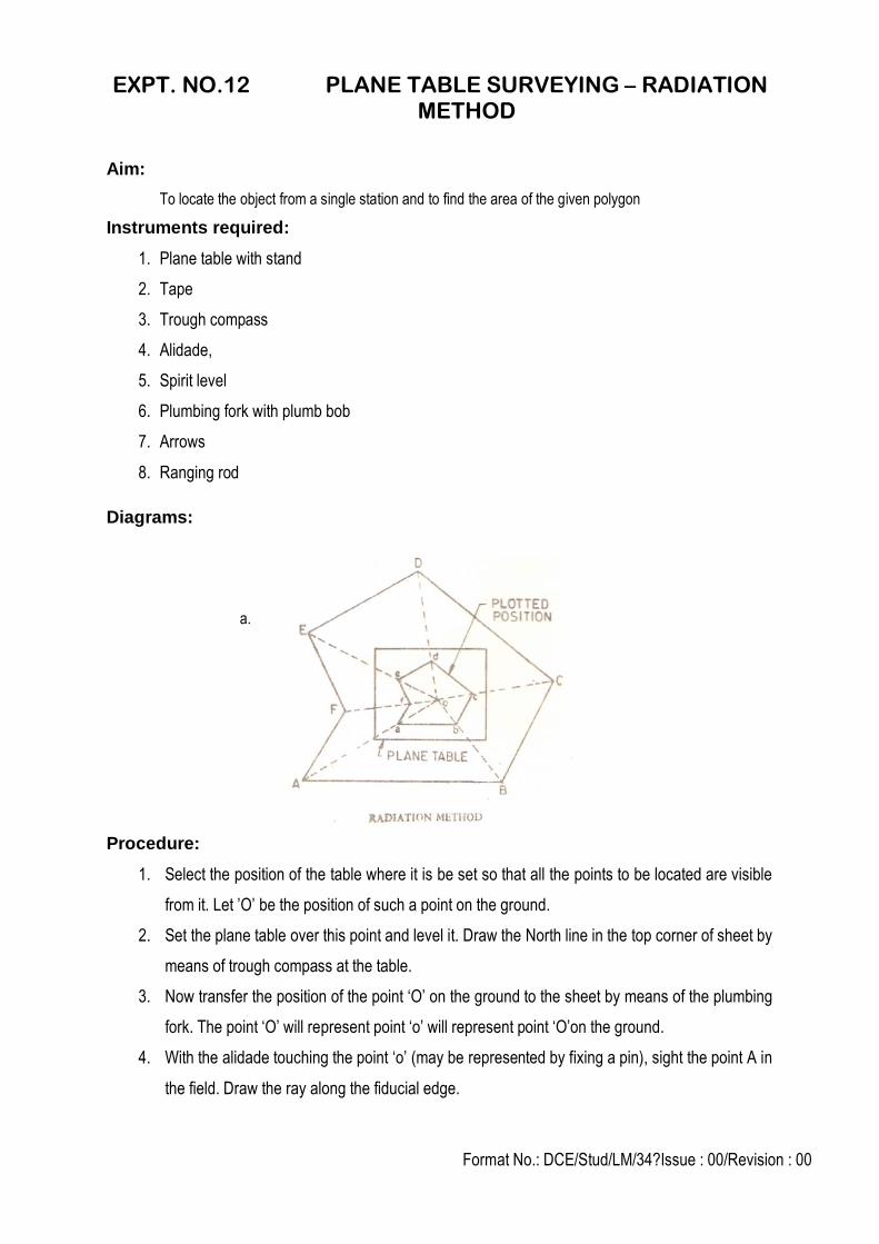
EXPT. NO.12 PLANE TABLE SURVEYING – RADIATION METHOD
Aim:
To locate the object from a single station and to find the area of the given polygon
Instruments required:
1. Plane table with stand
2. Tape
3. Trough compass
4. Alidade,
5. Spirit level
6. Plumbing fork with plumb bob
7. Arrows
8. Ranging rod
Diagrams:
a.
Procedure:
1. Select the position of the table where it is be set so that all the points to be located are visible
from it. Let ’O’ be the position of such a point on the ground.
2. Set the plane table over this point and level it. Draw the North line in the top corner of sheet by
means of trough compass at the table.
3. Now transfer the position of the point ‘O’ on the ground to the sheet by means of the plumbing
fork. The point ‘O’ will represent point ‘o’ will represent point ‘O’on the ground.
4. With the alidade touching the point ‘o’ (may be represented by fixing a pin), sight the point A in
the field. Draw the ray along the fiducial edge.
Format No.: DCE/Stud/LM/34?Issue : 00/Revision : 00
5. Similarly sight other points such as B, C, D, E etc. and measure their distances from the
instrument station. Plot them to scale to get their position on the sheet such as b, c, d etc. on
the sheet.
Calculations:
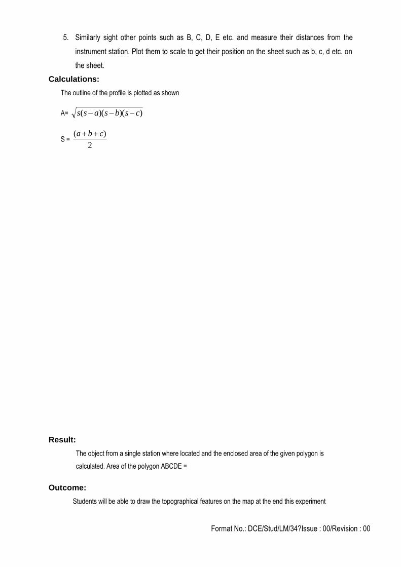
The outline of the profile is plotted as shown
A= ))()(( csbsass
S = 2
)( cba
Result:
The object from a single station where located and the enclosed area of the given polygon is
calculated. Area of the polygon ABCDE =
Outcome:
Students will be able to draw the topographical features on the map at the end this experiment
Format No.: DCE/Stud/LM/34?Issue : 00/Revision : 00
1. Mention the suitability and unsuitability of plane tabling.
2. When you adopt radiation method?
3. How you fix the north?
4. What is centering?
5. What are the equipments used in plane tabling?
6. What is orientation? Why it is to be performed?
7. What are bearings? Name the types.
8. What is an alidade? State its uses.
9. What is meridian? Name the types.
10. What is magnetic declination?
11. Enlist the disadvantages of plane table surveying.
12. What is orientation? Why is it done?
13. What is magnetic meridian?
14. What is whole circle bearing?
15. Differentiate between magnetic declination and dip.
1. The field observations and plotting are done simultaneously.
2. A plane table is set over a point and brought to precise horizontal level. 3. The alidade as a surveying level, information on the topography of the site can be directly
recorded on the drawing as elevations.
Viva-voce
Applications
Format No.: DCE/Stud/LM/34?Issue : 00/Revision : 00
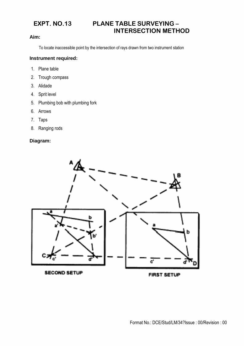
EXPT. NO.13 PLANE TABLE SURVEYING – INTERSECTION METHOD
Aim:
To locate inaccessible point by the intersection of rays drawn from two instrument station
Instrument required:
1. Plane table
2. Trough compass
3. Alidade
4. Sprit level
5. Plumbing bob with plumbing fork
6. Arrows
7. Taps
8. Ranging rods
Diagram:
Format No.: DCE/Stud/LM/34?Issue : 00/Revision : 00
Procedure:
1. Select two points L and M in such a way so that all the points to be plotted are visible from
them. Now set the table at station, point L in such a position so that the sheet should cover all
the points. Level the table and clamp it.
2. Draw the north line in the top corner of sheet by means of trough compass
3. Now transfer the position of station point L on the sheet as ‘l’ with the help of plumbing fork so
that it is vertically above the instrument station.
4. With the alidade pivoted about ‘l’ sight the ranging rod fixed at station point M and draw the
line in the direction of M. Now measure the distance LM by means of the tape and cut off lm to
some suitable scale along the ray drawn toward M; thus fixing the position of ‘m’ on the sheet
corresponding to station point M on the ground. The line lm is called the base line.
5. With the alidade touching the point ’l’ sight the objects in the field such as A,B,C,D,E etc. as
shown in figure and draw the rays towards them. The direction of each line is marked with an
arrow and a letter A, B, C, D,E etc. corresponding to above details.
6. Now shift the table to the station point M and approximately set it in the line with ML. Set it up
so that the point ‘m’ is vertically above the station point ‘M’ and level it.
7. Orient the table roughly by compass, then finally by placing the alidade along ml and bisecting
the ranging rod fixed at station point ‘L’ i.e. by back sighting ‘L’. Clamp the table in this
position.
8. With the alidade centered at m sight the same object in the field such as A, B, C, D, E etc; and
draw rays. The intersection of these rays with the respective rays from l locate the object
A,B,C,D,E etc; as a ,b,c,d,e, etc; on the sheet.
Result:
The Distance between two inaccessible point is = ………..………. m.
Outcome:
Students will be able to found the inaccessible points distance at the end this experiment
Format No.: DCE/Stud/LM/34?Issue : 00/Revision : 00
1. What are back sights and fore sights?
2. What is the objective of plane table intersection?
3. When we use plane table intersection?
4. What is the use of trough compass?
5. What is orientation? Why it is to be performed?
6. What are bearings? Name the types.
7. What is an alidade? State its uses.
8. What is meridian? Name the types.
9. What is magnetic declination?
10. Enlist the disadvantages of plane table surveying.
11. What is orientation? Why is it done?
12. What is magnetic meridian?
13. What is whole circle bearing?
14. Differentiate between magnetic declination and dip.
1. The field observations and plotting are done simultaneously.
2. A plane table is set over a point and brought to precise horizontal level.
3. The alidade as a surveying level, information on the topography of the site can be directly recorded on the
drawing as elevations.
Viva-voce
Applications