dhanalakshmi college of engineering, chennai department of mechanical engineering … ·...
TRANSCRIPT
DHANALAKSHMI COLLEGE OF ENGINEERING, CHENNAI
DEPARTMENT OF MECHANICAL ENGINEERING
ME 6404 THERMAL ENGINEERING
UNIT - I GAS POWER CYCLES
PART – A (2 Marks)
1. List the assumption made in Air standard cycle. (A/M – 11, A/M – 13) (i) Air is the working fluid and it obeys the perfect gas laws. (ii) The engine operates in a closed cycle. The cylinder is filled with constant amount of working
substance and the same fluid is used repeatedly and hence mass remains constant. (iii) The working fluid is homogeneous throughout at all times and no chemical reaction
takes place, inside the cylinder. (iv) The compression and expansion processes are assumed to be adiabatic. (v) The values of specific heat (Cp and Cv) of the working fluid remains constant. (vi) All processes are internally reversible and no mechanical or frictional losses to occur
throughout the process. (vii) Combustion is replaced by heat addition process and exhaust is replaced by heat
rejection process.
2. Define – Compression Ratio It is defined as the ratio of the stroke volume of cylinder to the clearance volume.
3. Define – Mean Effective Pressure (N/D – 09, A/M – 12, N/D – 13, N/D – 11)
It is defined as the average pressure acting on the piston during the entire power stroke that would produce the same amount of net work output during the actual cycle. It is also defined as the ratio of work-done per cycle to swept volume.
4. Define – Clearance Volume ( N/D – 09)
It is the minimum volume occupied by the fluid in the cylinder when the piston reaches the top dead centre position.
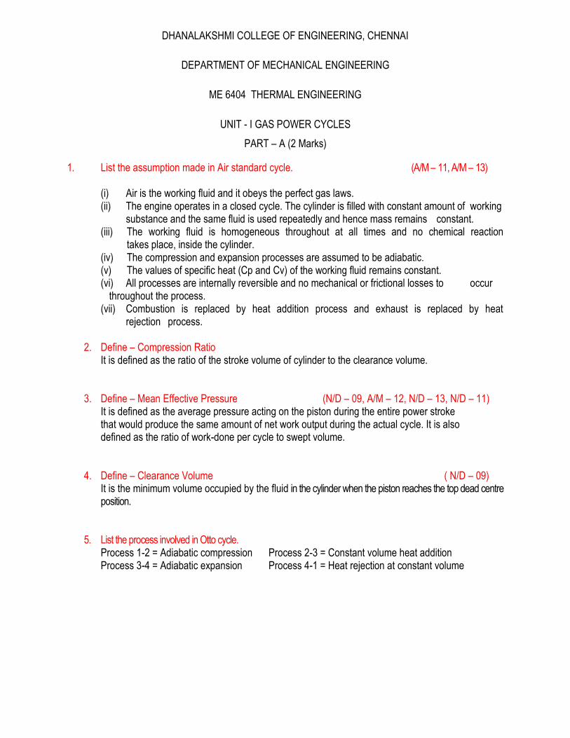
5. List the process involved in Otto cycle. Process 1-2 = Adiabatic compression Process 2-3 = Constant volume heat addition Process 3-4 = Adiabatic expansion Process 4-1 = Heat rejection at constant volume
6. Draw P-V and T-S diagram for Otto cycle. (A/M – 12)
7. Write the expression for air standard efficiency and mean effective pressure of an Otto cycle.
1
11
rOtto
)1)(1(
)1)(1(1
1
r
rrpp
m
8. Write the condition for maximum work of an Otto cycle? T2 = T 4 = (T1 T3)1 /2
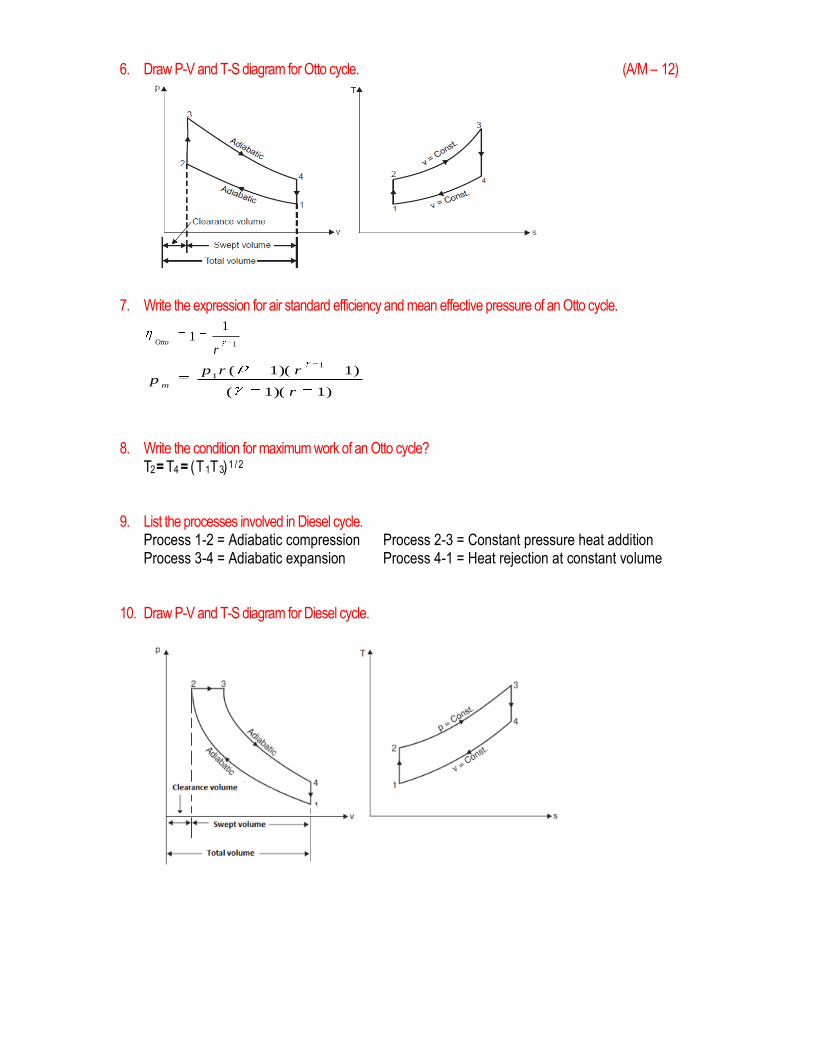
9. List the processes involved in Diesel cycle. Process 1-2 = Adiabatic compression Process 2-3 = Constant pressure heat addition Process 3-4 = Adiabatic expansion Process 4-1 = Heat rejection at constant volume
10. Draw P-V and T-S diagram for Diesel cycle.
11. Write the expression for air standard efficiency and mean effective pressure of Diesel cycle.
1
1.
.
11
1
c
c
Diesel
r
r
r
)1)(1(
)1()1(1
1
r
rrrrpP
cc
m
12. For same compression ratio efficiency of Otto cycle is greater than Diesel cycle. Why? The efficiency of the diesel cycle is 1-1/γr-1 x ργ-1/γ (ρ-1) The efficiency of the diesel cycle for the constant compression ratio depends upon the factor K=1/γr-1 x ρr-1/γ (ρ-1)
For the value of γ = 1.4, the value of the factor K for different cut- off ratios is given under ρ = 3 2.5 2 1.5 K = 1.31 1.24 1.17 1.092
Thus we see that the value of is always greater than unity and thus we can deduce that for the compression ratio, the efficiency of the Otto cycle is greater than that of the Diesel cycle.
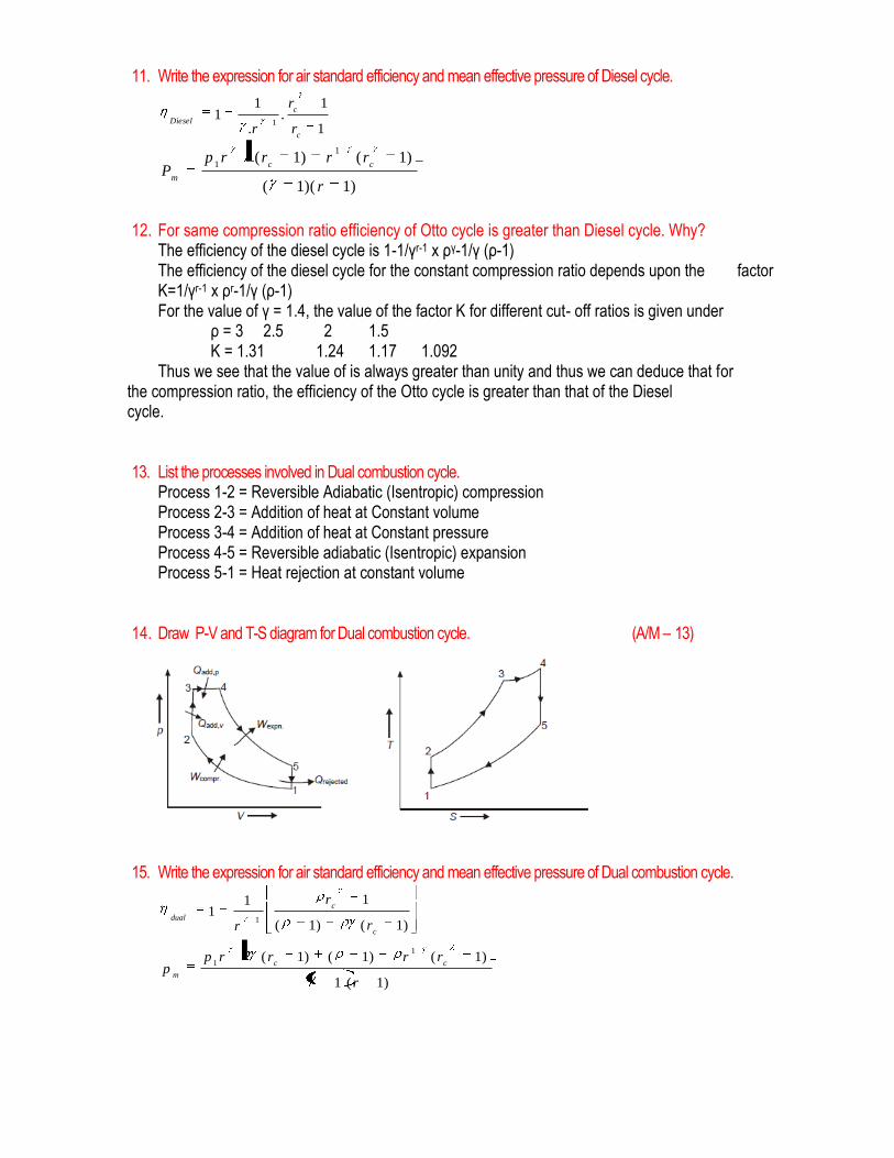
13. List the processes involved in Dual combustion cycle. Process 1-2 = Reversible Adiabatic (Isentropic) compression Process 2-3 = Addition of heat at Constant volume Process 3-4 = Addition of heat at Constant pressure Process 4-5 = Reversible adiabatic (Isentropic) expansion Process 5-1 = Heat rejection at constant volume
14. Draw P-V and T-S diagram for Dual combustion cycle. (A/M – 13)
15. Write the expression for air standard efficiency and mean effective pressure of Dual combustion cycle.
)1()1(
111
1
c
c
dual
r
r
r
)1(1
)1()1()1(1
1
r
rrrrpp
cc
m
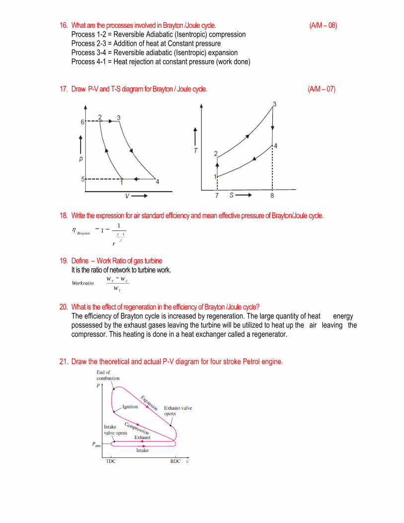
16. What are the processes involved in Brayton /Joule cycle. (A/M – 08) Process 1-2 = Reversible Adiabatic (Isentropic) compression Process 2-3 = Addition of heat at Constant pressure Process 3-4 = Reversible adiabatic (Isentropic) expansion Process 4-1 = Heat rejection at constant pressure (work done)
17. Draw P-V and T-S diagram for Brayton / Joule cycle. (A/M – 07)
18. Write the expression for air standard efficiency and mean effective pressure of Brayton/Joule cycle.
1
11
r
Brayton
19. Define – Work Ratio of gas turbine It is the ratio of network to turbine work.
T
CT
W
WWWorkratio
20. What is the effect of regeneration in the efficiency of Brayton /Joule cycle? The efficiency of Brayton cycle is increased by regeneration. The large quantity of heat energy possessed by the exhaust gases leaving the turbine will be utilized to heat up the air leaving the compressor. This heating is done in a heat exchanger called a regenerator.
21. Draw the theoretical and actual P-V diagram for four stroke Petrol engine.
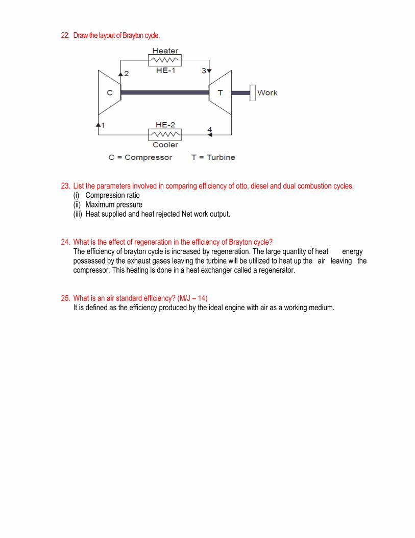
22. Draw the layout of Brayton cycle.
23. List the parameters involved in comparing efficiency of otto, diesel and dual combustion cycles. (i) Compression ratio (ii) Maximum pressure (iii) Heat supplied and heat rejected Net work output.
24. What is the effect of regeneration in the efficiency of Brayton cycle? The efficiency of brayton cycle is increased by regeneration. The large quantity of heat energy possessed by the exhaust gases leaving the turbine will be utilized to heat up the air leaving the compressor. This heating is done in a heat exchanger called a regenerator.
25. What is an air standard efficiency? (M/J – 14) It is defined as the efficiency produced by the ideal engine with air as a working medium.
Part – B (16 Marks)
1. Derive the expression for an air standard efficiency and mean effective pressure of an Otto cycle
2. The minimum pressure and temperature in an Otto cycle are 100kPa and 27 0C. The amount of
heat added to the air per cycle is 1500 kJ/kg. Determine, (i) the pressure and temperature at all
points of the air standard Otto cycle, (ii) Specific work and (iii) Thermal efficiency of the cycle for a
compression ratio of 8:1. Take for air, Cp = 0.72 kJ/kg K and Ƴ=1.4.
3. An engine working on Otto cycle has a volume of 0.45 m3, pressure 1bar and temperature 30°C at
the beginning of compression stroke. At the end of compression stroke, the pressure is 11 bar. 210
kJ of heat is added at constant volume. Determine : (i) Pressures, temperatures and volumes at
salient points in the cycle, (ii) Percentage clearance, (iii) Efficiency, (iv) Net work per cycle, (v)
Mean effective pressure and (vi) Ideal power developed by the engine if the number of working
cycles per minute is 210. Assume the cycle is reversible.
4. Derive the expression for an air standard efficiency and mean effective pressure of Diesel cycle.
5. An engine with 200 mm cylinder diameter and 300 mm stroke works on theoretical Diesel cycle. The initial pressure and temperature of air used are 1 bar and 27°C. The cut-off is 8% of the stroke. Determine : (i) Pressures and temperatures at all salient points, (ii) Theoretical air standard efficiency, (iii) Mean effective pressure and (iv) Power of the engine if the working cycles per minute are 380. Assume that compression ratio is 15 and working fluid is air. Consider all conditions to be ideal.
6. Derive the expression for an air standard efficiency and mean effective pressure of Dual cycle. (AU May / June 2014)
7. The compression ratio for a single-cylinder engine operating on dual cycle is 9. The maximum pressure in the cylinder is limited to 60 bar. The pressure and temperature of the air at the beginning of the cycle are 1 bar and 30°C. Heat is added during constant pressure process upto 4 per cent of the stroke. Assuming the cylinder diameter and stroke length as 250 mm and 300 mm respectively, determine: (i) The air standard efficiency of the cycle, (ii) The power developed if the number of working cycles are 3 per second. Take for air Cv = 0.71 kJ/kg K and : Cp = 1.0. kJ/kg K
8. An I.C. engine operating on the dual cycle (limited pressure cycle) the temperature of the working
fluid (air) at the beginning of compression is 27°C. The ratio of the maximum and minimum pressures of the cycle is 70 and compression ratio is 15. The amounts of heat added at constant volume and at constant pressure are equal. Compute the air standard thermal efficiency of the cycle. State three main reasons why the actual thermal efficiency is different from the theoretical value. Take γ for air = 1.4.
9. The compression ratio and expansion ratio of an oil engine working on the dual cycle are 9 and 5 respectively. The initial pressure and temperature of the air are 1 bar and 30°C. The heat liberated
at constant pressure is twice the heat liberated at constant volume. The expansion and compression follow the law pV1.25 = constant. Determine, (i) Pressures and temperatures at all salient points, (ii) Mean effective pressure of the cycle, (iii) Efficiency of the cycle and (iv) Power of the engine if working cycles per second are 8. Assume, Cylinder bore = 250 mm and stroke length = 400 mm.
10. Compare Otto, Diesel and Dual combustion cycles.
11. Derive the expression for an air standard efficiency, pressure ratio for maximum work and work ratio for Brayton cycle.
12. Explain the methods for improvement of thermal efficiency of gas turbine power plant.
13. Explain effect of operating variables on thermal efficiency.
14. Consider an air standard cycle in which the air enters the compressor at 1.0 bar and 20°C. The pressure of air leaving the compressor is 3.5 bar and the temperature at turbine inlet is 600°C. Determine per kg of air, (i) Efficiency of the cycle, (ii) Heat supplied to air, (iii) Work available at the shaft, (iv) Heat rejected in the cooler and (v) Temperature of air leaving the turbine. For air γ = 1.4 and Cp = 1.005 kJ/kg K.
15. A closed cycle ideal gas turbine plant operates between temperature limits of 800°C and 30°C and produces a power of 100 kW. The plant is designed such that there is no need for a regenerator. A fuel of calorific value 45000 kJ/kg is used. Calculate the mass flow rate of air through the plant and rate of fuel consumption. Assume Cp = 1 kJ/kg K and γ = 1.4.
16. Air standard Diesel cycle has a compression ratio of 18. The pressure at the beginning of the compression stroke is 1 bar and the temperature is30 0C.The heat supplied is 1800 kJ/kg. Determine: (i) Thermal efficiency, (ii) Pressure and temperature at salient points, (iii) Heat rejected, (iv) Mean effective pressure. Assume, Cp and Cv , R and γ suitably. (AU Nov. 2013)
17. An Otto cycle has an compression ratio of 7. The initial pressure and temperature at the beginning of compression stroke is 1 bar and 40o C. The heat supplied is 2510 kJ/kg. Find (i) Maximum temperature and pressure, (ii) Work done per kg of air, (iii) Cycle efficiency and (iv) Mean effective pressure. Assume, Cp and Cv , R and γ suitably. (AU Nov. 2013)
18. Derive an expression for the air-standard efficiency of diesel cycle.Explain why the efficiency of Otto cycle is greater than that of the diesel cycle for the same compression ratio. (AU May 2013)
19. In an oil engine working on dual cycle the heat supplied at constant pressure is twice that of the heat supplied at constant volume.The compression and expansion ratios are 8 and 5.3.The pressure and at the beginning of compression are 0.93 bar and 27oC .Find the efficiency of the cycle and mean effective pressure.Take Cp and Cv as 1.005 kJ/kgK and 0.718 kJ/kigK.
20. Air standard Diesel cycle has a compression ratio of 8. The pressure at the beginning of the compression stroke is 1 bar and the temperature is300K.The heat supplied is 1800 kJ/kg. Determine: (i) Air Standard efficiency, (ii) Pressure and temperature at salient points, (iii) Mean effective pressure. Assume, Cp = 1.005 , R = 0.287. (AU May / June 2014)
UNIT - II INTERNAL COMBUSTION ENGINES
PART – A (2 Marks)
1. What is the function of cam shaft and crank shaft? (N/D – 13)
Cam shaft converts the rotary motion of cam into linear motion of the follower. It operates the inlet and
outlet valves through rocker arm.
Crank shaft converts the reciprocating motion of the piston into rotary motion.
2. List out the effects of detonation. (N/D – 12) a) Noise and roughness
b) Mechanical damage to the engine parts
c) Carbon deposit on cylinder walls
d) More heat transfer
e) Reduced efficiency and power
3. Define – Nozzle Efficiency (A/M – 13)
Nozzle efficiency is the ratio of actual enthalpy drop to the isentropic enthalpy drop.
dropenthalpyIsentropic
dropenthalpyActualefficiencyNozzle
4. What is the function of push rod and rocker arm? (A/M – 12)
The motion of the cam is transmitted to the valve through the push rod and rocker arm. These links
are jointly known as valve gear.
5. What are the basic requirements of a fuel injection system of a diesel engine? (A/M – 12) a) Constant supply of fuel from cycle to cycle operation
b) Uniform and constant supply of fuel from cylinder to cylinder
c) Atomization the fuel to the required level
d) Beginning of injection at proper timing
6. List out the various parameters involved in engine performance. (N/D – 11) a) Brake power
b) Indicated power
c) Friction power
d) Total fuel consumption
e) Specific fuel consumption
f) Thermal efficiency
g) Mechanical efficiency
h) Mean effective pressure
7. What is the effect of friction on the flow through a steam nozzle? (N/D – 11)
a) The expansion is no more isentropic and enthalpy drop is reduced, thereby resulting in exit
velocity.
b) The final dryness fraction of steam will be increased.
c) The specific volume of steam will be increased.
8. What is meant by splash lubrication? (A/M – 11)
Splash lubrication is applicable in small sized internal combustion engines. In this system, the oil from
the sump is splashed to the moving parts of the engine with spool. A small hole is drilled in the crank
shaft and the oil is forced through this hole to the bearings.
9. What is meant by supersaturated flow? (A/M – 10)
The steam may not have time to condense and remains dry when the expansion through the nozzle is
very rapid. This type of flow is called supersaturated flow.
10. What is the importance of delay period in CI engine combustion phenomena? (A/M – 11)
If the delay period is more, more diesel fuel will be injected in the combustion chamber and pressure
rise will be more. This leads to diesel knock.
But delay period is needed to disperse and atomize the fuel in the air for complete combustion. Hence
an optimum and required time should be given for the delay period depending on the combustion
characteristics of the engine.
11. What is meant by IC engine? (A/M – 10)
The Internal Combustion engine is a heat engine that converts chemical energy in a fuel into
mechanical energy. Chemical energy of a fuel is first converted into thermal energy by means of
combustion or oxidization with air inside the engine. This thermal energy is converted into useful work
through mechanical mechanism of the engine.
12. List out the various components of IC engines. (N/D – 10)
a) Cylinder block
b) Cylinder head
c) Crank case
d) Oil sump
e) Cylinder liners
f) Piston
13. State the purpose of providing piston in IC engines. (N/D – 10)
It acts as a movable gas tight seal to keep the gases inside the cylinder. And it also transmits the force
of explosion in the cylinder to the crankshaft through the connecting rod.
14. What is meant by scavenging, in I.C engines? (A/M – 09)
The process of removing the burnt gases from the combustion chamber of engine cylinder is known as
scavenging.
15. How are the CI combustion chambers of a diesel engine classified? (A/M – 09)
Non turbulent type – Open combustion engine
Turbulent type – (a) Turbulent chamber (b) Pre-combustion chamber (iii) Energy cell
Part – B (16 Marks)
1. A four cylinder, four stroke diesel engine has brake mean effective pressure of 6 bar at full load speed of 600 rpm and specific fuel consumption of 0.25 kg/kWh. The cylinder has bore of 20 cm and stroke length of 30 cm. The air fuel ratio is measured as 26 from the exhaust gas analysis. The ambient conditions are 1 bar, 27ºC. Assuming the calorific value of fuel as 43 MJ/kg determine the brake thermal efficiency and the volumetric efficiency. Also find out brake power.
2. A two stroke two cylinder engine runs with speed of 3000 rpm and fuel consumption of 5 litres/hr. The fuel has specific gravity of 0.7 and air-fuel ratio is 19. The piston speed is 500 m/min and indicated mean effective pressure is 6 bar. The ambient conditions are 1.013 bar, 15ºC. The volumetric efficiency is 0.7 and mechanical efficiency is 0.8. Determine brake power output considering R for gas = 0.287 kJ/kgK. (Take piston speed, m/min = 2 LN where L is stroke (m) and N is rpm)
3. During trial of four stroke single cylinder engine the load on dynamometer is found 20 kg at radius of 50 cm. The speed of rotation is 3000 rpm. The bore and stroke are 20 cm and 30 respectively. Fuel is supplied at the rate of 0.15 kg/min. The calorific value of fuel may be taken as 43 MJ/kg. After some time the fuel supply is cut and the engine is rotated with motor which required 5 kW to maintain the same speed of rotation of engine. Determine the brake power, indicated power, mechanical efficiency, brake thermal efficiency, indicated thermal efficiency, brake mean effective pressure, indicated mean effective pressure.
4. A four stroke four cylinder diesel engine running at 300 rpm produces 250 kW of brake power. The cylinder dimensions are 30 cm bore and 25 cm stroke. Fuel consumption rate is 1 kg/min while air fuel ratio is 10. The average indicated mean effective pressure is 0.8 MPa. Determine indicated power, mechanical efficiency, brake thermal efficiency and volumetric efficiency of engine. The calorific value of fuel is 43 MJ/kg. The ambient conditions are 1.013 bar, 27ºC.
5. During an experiment on four stroke single cylinder engine the indicator diagram obtained has average
height of 1 cm while indicator constant is 25 kN/m2 per mm. The engine run at 300 rpm and the swept volume is 1.5 × 104 cm3. The effective brake load upon dynamometer is 60 kg while the effective brake drum radius is 50 cm. The fuel consumption is 0.12 kg/min and the calorific value of fuel oil is 42 MJ/kg. The engine is cooled by circulating water around it at the rate of 6 kg/min. The cooling water enters at 35º C and leaves at 70ºC. Exhaust gases leaving have energy of 30 kJ/s with them. Take specific heat of water as 4.18 kJ/kg K. Determine indicated power output, brake power output and mechanical efficiency. Also draw the overall energy balance in kJ/s.
6. During 15 minutes trial of an internal combustion engine of 2-stroke single cylinder type the total 4 kg fuel is consumed while the engine is run at 1500 rpm. Engine is cooled employing water being circulated at 15 kg/min with its inlet and exit temperatures as 27ºC and 50ºC. The total air consumed is 150 kg and the exhaust temperature is 400ºC. The atmospheric temperature is 27ºC. The mean specific heat of exhaust gases may be taken as 1.25 kJ/kg K. The mechanical efficiency is 0.9. Determine the brake power, brake specific fuel consumption and indicated thermal efficiency. Also draw energy balance on per minute basis. Brake torque is 300 Nm and the fuel calorific value is 42 MJ/kg.
7. During Morse Test experiment on a six cylinder petrol engine the brake power output was found 50 kW when all cylinders run at full load. When one by one each cylinder is cut and load is reduced to bring engine back to original speed, the measured brake power outputs are as under. Determine the indicated power of engine and mechanical efficiency of engine.
8. During trial of a four cylinder four stroke petrol engine running at full load it has speed of 1500 rpm and brake load of 250 N when all cylinders are working. After some time each cylinder is cut one by one and then again brought back to same speed of engine. The brake readings are measured as 175 N, 180 N, 182 N and 170 N. The brake drum radius is 50 cm. The fuel consumption rate is 0.189 kg/min with the fuel whose calorific value is 43 MJ/kg and A/F ratio of 12. Exhaust gas temperature is found to be 600ºC. The cooling water flows at 18 kg/min and enters at 27ºC and leaves at 50ºC. The atmospheric air temperature is 27ºC. Take specific heat of exhaust gas as 1.02 kJ/kg K. Determine the brake power output of engine, its indicated power and mechanical efficiency. Also draw a heat balance on per minute basis.
9. During the trial of a single acting oil engine, cylinder diameter is 20 cm, stroke 28 cm, working on two stroke cycle and firing every cycle, the following observations were made: Duration of trial = 1 hour Total fuel used = 4.22 kg Calorific value = 44670 kJ/kg Proportion of hydrogen in fuel = 15% Total number of revolutions = 21000 Mean effective pressure = 2.74 bar Net brake load applied to a drum = 600 N Drum Diameter = 100 cm Total mass of cooling water circulated = 495 kg , Cooling water enters at 13ºC and leaves at 380C, Air used = 135 kg Temperature of air in test room = 200C Temperature of exhaust gases = 3700C, Cpgases = 1.005 kJ/kgK Cp steam at atm = 2.093 kJ/kg K Calculate thermal efficiency and draw up the heat balance.
10. With neat sketch, briefly explain components of I C engine.
11. With neat sketch, explain the working of four stroke petrol engine
12. With neat sketch, explain the working of four stroke diesel engine.
13. (i) Compare two stroke and four stroke I C engines.
(ii) Differentiate petrol engine and diesel engine.
14. Explain in detail about working of diesel pump & diesel injector with neat sketch.
15. Explain in detail the working of battery ignition system with neat sketch.
16. Explain formation of exhaust emission in SI and CI engines.
17. Discuss the construction and working of a 4 stroke engine with sketch.(AU Dec.2013)
18. Explain Battery coil ignition system with a neat sketch. (AU Dec.2013)
19. (a) Explain the function and working of a fuel injector with a neat sketch. (b) Draw and explain the Port timing diagram of a 2 stroke diesel engine.(8 Marks) (AU May 2013)

20. What are the different methods of lubricating IC engine? Explain the pressure system of lubrication with neat sketch. (AU May / June 2014)
21. The following observations were taken during a test on a single cylinder 4 stroke cycle engine
having a bore of 300 mm and a stroke of 450 mm. (AU May 2013)
UNIT - III STEAM NOZZLES AND TURBINES
PART – A (2 Marks)
1. What is steam nozzle?
A steam nozzle is defined as a passage of varying cross section, through which heat energy of
steam is converted to kinetic energy. Its major function is to produce steam jet with high velocity to
drive steam turbines.
2. Define – Critical Pressure Ratio ( N/D – 13)
The critical pressure ratio is the pressure ratio which will accelerate the flow to a velocity equal to
the local velocity of sound in the fluid. The maximum gas flow through a nozzle is determined by the
critical pressure. The pressure which the area is minimum and discharge per unit area is maximum is
called critical pressure ratio.
Critical pressure ratio = (p2/p1) = (2/(n+1))(n/(n-1))
3. List the effects of friction in nozzle. (M/J – 14)
In practice, there is friction produced between the steam and the sides of the nozzle; this friction
causes a resistance to the flow which is converted into heat. The heat formed tends drying the steam.
i) The expansion is no more isentropic and enthalpy drop is reduced
ii) The final dryness fraction of steam is increased as the kinetic energy gets converted in
to heat due to friction and is absorbed by steam.
iii) The specific volume of steam is increased as the steam becomes more dry due to this
frictional reheating.
4. Define – Nozzle Efficiency ( N/D – 13)
The nozzle efficiency is therefore defined as the ratio of the actual enthalpy drop to the
isentropic enthalpy drop between the same pressures.
Nozzle efficiency = (actual enthalpy drop) / (isentropic enthalpy drop)
5. What do you mean by supersaturated or metastable flow in steam nozzle?
When steam flows through a nozzle, it would normally be expected that the discharge of steam
through the nozzle would be slightly less than the theoretical value. But it has been observed
during experiments on flow of wet steam that the discharge is slightly greater than that calculated
by the formula. The converging part of the nozzle is so short and the steam velocity so high that the
molecules of steam have insufficient time to collect and form droplets so that normal condensation does
not take place. Such rapid expansion is said to be metastable and produces a supersaturated state.
6. What are the effects of super saturation?
i) There is an increase in the entropy and specific volume of steam
ii) The heat drop is reduced below that for thermal equilibrium as an consequence the exit
velocity is reduced.
iii) The density of supersaturated steam will be more than for the equilibrium conditions
which gives the increase in the mass of steam discharged.
iv) The dryness fraction of steam is improved.
7. List the factors, which influence nozzle efficiency.
When the steam flows through a nozzle the final velocity of steam for given pressure
drop is reduced due to the following reasons
i) The friction between the nozzle surface and steam
ii) The internal friction of steam itself
iii) The shock losses.
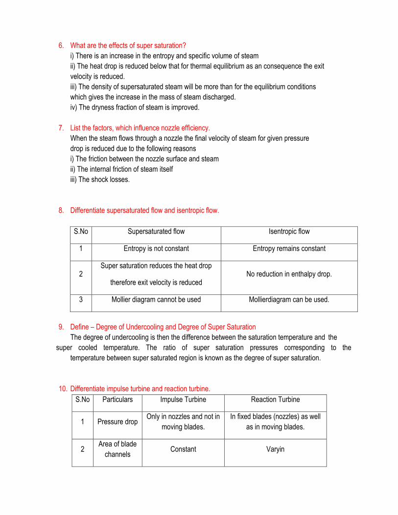
8. Differentiate supersaturated flow and isentropic flow.
S.No Supersaturated flow Isentropic flow
1 Entropy is not constant Entropy remains constant
2 Super saturation reduces the heat drop
therefore exit velocity is reduced No reduction in enthalpy drop.
3 Mollier diagram cannot be used Mollierdiagram can be used.
9. Define – Degree of Undercooling and Degree of Super Saturation
The degree of undercooling is then the difference between the saturation temperature and the
super cooled temperature. The ratio of super saturation pressures corresponding to the
temperature between super saturated region is known as the degree of super saturation.
10. Differentiate impulse turbine and reaction turbine.
S.No Particulars Impulse Turbine Reaction Turbine
1 Pressure drop Only in nozzles and not in
moving blades.
In fixed blades (nozzles) as well
as in moving blades.
2 Area of blade
channels Constant Varyin
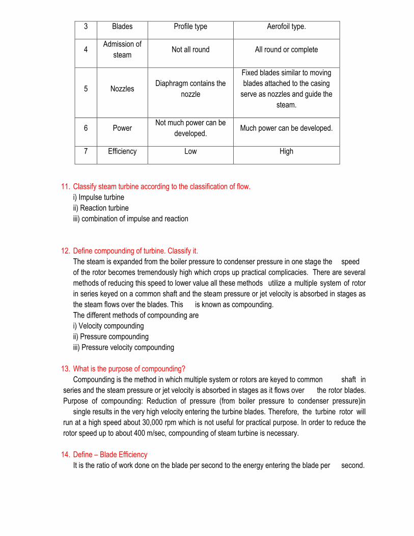
3 Blades Profile type Aerofoil type.
4 Admission of
steam Not all round All round or complete
5 Nozzles Diaphragm contains the
nozzle
Fixed blades similar to moving
blades attached to the casing
serve as nozzles and guide the
steam.
6 Power Not much power can be
developed. Much power can be developed.
7 Efficiency Low High
11. Classify steam turbine according to the classification of flow.
i) Impulse turbine
ii) Reaction turbine
iii) combination of impulse and reaction
12. Define compounding of turbine. Classify it.
The steam is expanded from the boiler pressure to condenser pressure in one stage the speed
of the rotor becomes tremendously high which crops up practical complicacies. There are several
methods of reducing this speed to lower value all these methods utilize a multiple system of rotor
in series keyed on a common shaft and the steam pressure or jet velocity is absorbed in stages as
the steam flows over the blades. This is known as compounding.
The different methods of compounding are
i) Velocity compounding
ii) Pressure compounding
iii) Pressure velocity compounding
13. What is the purpose of compounding?
Compounding is the method in which multiple system or rotors are keyed to common shaft in
series and the steam pressure or jet velocity is absorbed in stages as it flows over the rotor blades.
Purpose of compounding: Reduction of pressure (from boiler pressure to condenser pressure)in
single results in the very high velocity entering the turbine blades. Therefore, the turbine rotor will
run at a high speed about 30,000 rpm which is not useful for practical purpose. In order to reduce the
rotor speed up to about 400 m/sec, compounding of steam turbine is necessary.
14. Define – Blade Efficiency
It is the ratio of work done on the blade per second to the energy entering the blade per second.
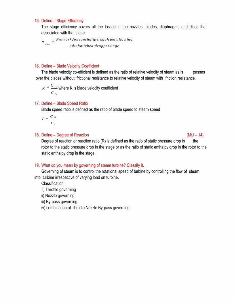
15. Define – Stage Efficiency
The stage efficiency covers all the losses in the nozzles, blades, diaphragms and discs that
associated with that stage.
stage
N etw orkdoneonsha ftperkgo fsteam flow ing
ad iaba tichea tdropperstage
16. Define – Blade Velocity Coefficient
The blade velocity co-efficient is defined as the ratio of relative velocity of steam as is passes
over the blades without frictional resistance to relative velocity of steam with friction resistance.
0
1
r
r
CK
C
where K is blade velocity coefficient
17. Define – Blade Speed Ratio
Blade speed ratio is defined as the ratio of blade speed to steam speed
1
b lC
C
18. Define – Degree of Reaction (M/J – 14)
Degree of reaction or reaction ratio (R) is defined as the ratio of static pressure drop in the
rotor to the static pressure drop in the stage or as the ratio of static enthalpy drop in the rotor to the
static enthalpy drop in the stage.
19. What do you mean by governing of steam turbine? Classify it.
Governing of steam is to control the rotational speed of turbine by controlling the flow of steam
into turbine irrespective of varying load on turbine.
Classification
i) Throttle governing
ii) Nozzle governing
iii) By-pass governing
iv) combination of Throttle Nozzle By-pass governing.
Part – B (16 Marks)
1. Determine the mass flow rate of steam through a nozzle having isentropic flow through it. Steam enters nozzle at 10 bar, 5000C and leaves at 6 bar. Cross-section area at exit of nozzle is 20 cm2. Velocity of steam entering nozzle may be considered negligible. Show the process on h-s diagram also.
2. In a nozzle steam expands from 12 bar and 3000C to 6 bar with flow rate of 5 kg/s. Determine throat and exit area if exit velocity is 500 m/s and velocity at inlet to nozzle is negligible. Also find coefficient of velocity at exit. Coefficient of velocity is the ratio of actual velocity of fluid at nozzle exit to the velocity at exit considering isentropic flow through nozzle.
3. In a steam nozzle steam expands from 16 bar to 5 bar with initial temperature of 3000C and mass flow of 1 kg/s. Determine the throat and exit areas considering (i) expansion to be frictionless and, (ii) friction loss of 10% throughout the nozzle.
4. An impulse turbine of 1 MW has steam entering at 20 bar and 3000C and steam consumption of 8 kg per kWh. Steam leaves at 0.2 bar and 10% of total heat drop is lost in overcoming friction in diverging portion of nozzle. If throat diameter of each nozzle is 1 cm then determine (i) the number of nozzles required (ii) exit diameter of each nozzle. Solve using mollier diagram.
5. A nozzle is supplied with steam at 0.7 mPa and 2750C. Determine temperature and velocity at throat considering no losses. If diverging portion of nozzle is 6 cm long and throat diameter of 0.5 cm, determine the angle of cone in nozzle so that steam leaves nozzle at 0.1 MPa. Assume heat utilization in diverging portion to be 85%. Solve using mollier diagram.
6. A convergent-divergent nozzle operates with 5 kg of steam per minute being discharged at 1 bar. For the steam supplied to nozzle being at 10 bar and 2000C and supersaturation occurring up to throat and normal afterwards, determine, (i) the diameter of nozzle at exit, (ii) the maximum degree of supersaturation, (iii) the amount of undercooling at throat. For supersaturation take Pv1.3 = constant and P / T 1.3/0.3 = constant.
7. The flow rate through steam nozzle with isentropic flow from pressure of 13 bar was found 60 kg/min. steam is initially saturated. Determine the throat area. If the flow is super saturated, determine the increase in flow rate. ( AU, May/ June 2014)
8. In a single stage impulse turbine the isentropic enthalpy drop of 200 kJ/kg occurs in the nozzle having efficiency of 96% and nozzle angle of 15°. The blade velocity coefficient is 0.96 and ratio of blade speed to steam velocity is 0.5. The steam mass flow rate is 20 kg/s and velocity of steam entering is 50 m/s. Determine (a) the blade angles at inlet and outlet if the steam enters blades smoothly and leaves axially, (b) the blade efficiency, (c) the power developed in kW and (d) the axial thrust.
9. Steam enters the blade row of an impulse turbine with the velocity of 600 m/s at an angle of 25° to the plane of rotation of the blades the blade mean speed is 250 m/s. The blade angle at the exit
side is 30°. The blade friction loss is 10 percentage. Determine blade angle inlet, blade efficiency and work done per kg of steam. ( AU, May/ June 2014)
10. Following data refer to a De Laval steam turbine having equiangular blades; Steam entering nozzle = 100 m/s Nozzle efficiency = 0.9 Blade speed = 200 m/s Blade velocity co-efficient = 0.85 Rate of steam mass flow = 3 kg/s Absolute velocity of steam at exit from stage with tangent of wheel = 750 Determine, (a) Blade angles, (b) Nozzle angle, (c) Absolute velocity of steam at inlet, (d) axial thrust and (e) Power developed.
11. In a simple impulse steam turbine stage steam enters the nozzle at 15 bar, dry saturated with velocity of 150 m/s. Nozzle angle is 20° and steam leaves nozzle at 8 bar and enters into smooth blades. Considering nozzle velocity coefficient of 0.90 and blades to be equiangular determine the following for maximum diagram efficiency, (a) the blade angles, (b) the blading efficiency and (c) the stage efficiency.
12. In a Parson’s reaction turbine the rotor of 1m diameter runs at 3000 rpm. Determine the isentropic enthalpy drop in the stage considering stage efficiency of 0.80 , ρ = 0.7, blade outlet angle = 20°.
13. A Parson’s reaction turbine has mean diameter of blades as 1.6 m and rotor moving at 1500 rpm. The inlet and outlet angles are 80° and 20° respectively. Turbine receives steam at 12 bar, 200°C and has isentropic heat drop of 26 kJ/kg. 5% of steam supplied is lost through leakage. Determine the following considering horse power developed in stage to be 600 hp.(a) the stage efficiency and (b) the blade height.
14. Steam expands isentropically in a nozzle from 1 MPa , 250o C to 10 KPa . The flow rate of the steam is 1 kg/ s. Find the following when the inlet velocity is neglected, (i) Quality of steam, (ii) Velocity of steam at the exit of the nozzle, (iii)Exit area of the nozzle. (AU Dec.2013)
15. Explain the pressure band velocity compounding of a multi stage turbine. ( AU Dec. 2013 )
16. (a) What are the effects of friction in a nozzle? Explain. (8)
(b) A convergent-divergent nozzle is required to discharge 2 kg/s of steam. The nozzle is supplied
with steam at 7 bar and 180oC and discharge takes place against a back pressure of 1 bar.the
expansion upto the throat is isentropic and the frictional resistance between=n the throat and the
exit is equivalent to 63 kJ/kg of steam. Taking approach velocity of 75m/s and throat pressure of 4
bar estimate suitable areas for throat and exit and Overall of the nozzle based on the enthalpy drop
between the actual inlet pressure and temperature and the exit pressure. (8) (AU May 2013)

17. (a) The velocity of steam leaving the nozzle of an impulse turbine is 10000m/s and the nozzle
angle is 20o . The blade ve3locity is 350m/s and the blade velocity of co-efficient is=s 0.85.Assuming
no losses due to shock at inlet ,calculate for a mass flow of 1.5kg/s ,and symmetrical blading, (i)
Blade inlet angle, (ii) Driving force on the wheel, (iii) Axial thrust on the wheel and (iv) Power
developed by the turbine.
(b) Differentiate between impulse and reaction turbine. (4) (AU May 2013)
UNIT – IV AIR COMPRESSOR
PART – A (2 Marks)
1. Classify compressors? (M/J – 14)
(i) According to number of stages: Single stage compressor and Multi stage compressor (ii) According to number of cylinders: Single cylinder compressor and Multi cylinder compressor (iii) According to method of cooling: Air and water cooled compressor. (iv) According to working : Reciprocating compressor and Rotary compressor (v) According to action of air : Single acting compressor and Double acting compressor (vi) According to pressure limit : Low, Medium and High pressure compressor (vii) According to capacity : Low, Medium and High capacity compressor
2. Differentiate positive and non-positive displacement compressors. Positive displacement compressor is one in which air is compressed adiabatically. The air is entrapped in between two sets of engaging surfaces. The pressure rise is either by back flow of air (as in roots blower) or both by variation in the flow and back flow (as in vane blower).
In non-positive displacement compressor, air is not trapped in specific boundaries but it flows continuously and steadily through the machine (as in centrifugal compressor and axial flow compressor).
3. Differentiate reciprocating and rotary air compressor.
Sl. No.
Reciprocating Air Compressor Rotary Air Compressor
1 Maximum delivery pressure may be 1000 bar. The maximum delivery pressure is 10 bar only.
2 They are suitable for low discharge of air at very high pressure.
They are suitable for large discharge of air at low pressure.
3 The speed of air compressor is low. The speed of air compressor is high.
4 The air supply is intermittent. The air supply is continuous.
5 The size of the compressor is large for the given discharge.
The size of air compressor is small for the same discharge.
6 The balancing is a major problem. There is no balancing problem.
4. Define – Compressor Mechanical Efficiency Compressor mechanical efficiency is defined as the ratio of indicated power to the brake power (shaft power).
5. Define – Isothermal Efficiency and Isentropic Efficiency of the Compressor Isothermal efficiency of the compressor is defined as the ratio of isothermal work input to actual work input during compression.
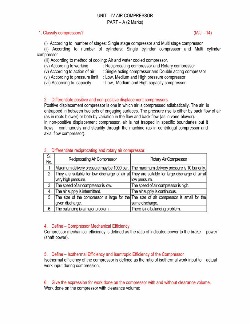
6. Give the expression for work done on the compressor with and without clearance volume. Work done on the compressor with clearance volume:
Work done on the compressor without clearance volume:
7. Why clearance volume is necessary and explain its importance? In actual compressor, the clearance volume is provided to give cushioning effect otherwise the piston will strike the other end of the cylinder. It is generally expressed as percentage of piston displacement. Importance of clearance volume: To give cushioning effect to the piston. To provide space for valve movement. The maximum pressure may also be controlled by clearance volume. The volumetric efficiency and pressure ratio depends upon clearance volume. If clearance volume is more, it reduces the volumetric efficiency.
8. What is meant by FAD? Free air delivered (FAD) means the actual volume of air delivered by the compressor under normal temperature and pressure.
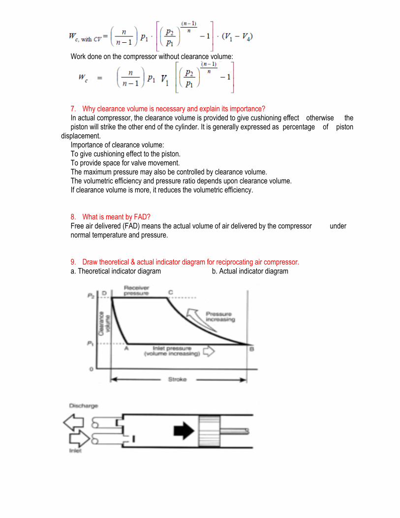
9. Draw theoretical & actual indicator diagram for reciprocating air compressor. a. Theoretical indicator diagram b. Actual indicator diagram
10. List advantages of multi stage compressor over single stage compressor.
(i) Less work is done by the compressor to deliver the same quantity of air. (ii) It improves the volumetric efficiency for the given pressure ratio. (iii) The size of two cylinders may be adjusted to suit the volume and pressure of the air. (iv) It reduces the leakage losses considerably and provides effective lubrication. (v) It provides more uniform torque and thus smaller size of the flywheel is required.
11. List the assumption made for multi stage compression. (i) For each stage, pressures during suction and delivery remain constant. (ii) The index (n) in polytropic law is same in each stage of compression. (iii) Inter-cooling in each stage is done at constant pressure. (iv) Low pressure and high pressure cylinder handle same mass of air. (v) There is no inter-stage pressure drop.
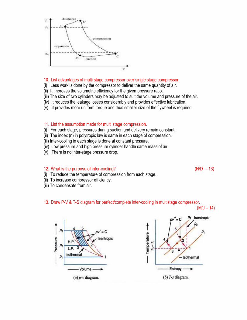
12. What is the purpose of inter-cooling? (N/D – 13) (i) To reduce the temperature of compression from each stage. (ii) To increase compressor efficiency. (iii) To condensate from air.
13. Draw P-V & T-S diagram for perfect/complete inter-cooling in multistage compressor. (M/J – 14)
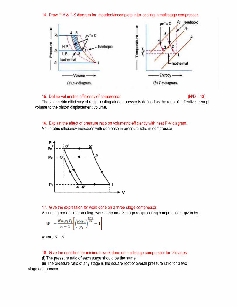
14. Draw P-V & T-S diagram for imperfect/incomplete inter-cooling in multistage compressor.
15. Define volumetric efficiency of compressor. (N/D – 13) The volumetric efficiency of reciprocating air compressor is defined as the ratio of effective swept
volume to the piston displacement volume.
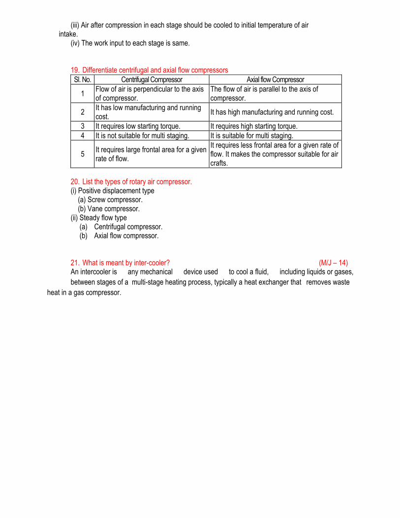
16. Explain the effect of pressure ratio on volumetric efficiency with neat P-V diagram. Volumetric efficiency increases with decrease in pressure ratio in compressor.
17. Give the expression for work done on a three stage compressor. Assuming perfect inter-cooling, work done on a 3 stage reciprocating compressor is given by,
where, N = 3.
18. Give the condition for minimum work done on multistage compressor for ‘Z’stages. (i) The pressure ratio of each stage should be the same. (ii) The pressure ratio of any stage is the square root of overall pressure ratio for a two stage compressor.
(iii) Air after compression in each stage should be cooled to initial temperature of air intake.
(iv) The work input to each stage is same.
19. Differentiate centrifugal and axial flow compressors
Sl. No. Centrifugal Compressor Axial flow Compressor
1 Flow of air is perpendicular to the axis of compressor.
The flow of air is parallel to the axis of compressor.
2 It has low manufacturing and running cost.
It has high manufacturing and running cost.
3 It requires low starting torque. It requires high starting torque.
4 It is not suitable for multi staging. It is suitable for multi staging.
5 It requires large frontal area for a given rate of flow.
It requires less frontal area for a given rate of flow. It makes the compressor suitable for air crafts.
20. List the types of rotary air compressor.
(i) Positive displacement type (a) Screw compressor. (b) Vane compressor. (ii) Steady flow type
(a) Centrifugal compressor. (b) Axial flow compressor.
21. What is meant by inter-cooler? (M/J – 14)
An intercooler is any mechanical device used to cool a fluid, including liquids or gases,
between stages of a multi-stage heating process, typically a heat exchanger that removes waste
heat in a gas compressor.
Part – B (16 Marks)
1. Explain the working principle of reciprocating air compressor with neat sketch.
2. Derive the expression for work done on reciprocating air compressor with clearance volume. 3. Derive the expression for work done by reciprocating air compressor without clearance volume. 4. Explain with neat sketch the working principle of multistage reciprocating compressor 5. Derive the expression for work done by multistage reciprocating compressor.
6. Reciprocating air compressor has cylinder with 24 cm bore and 36 cm stroke. Compressor admits air at 1 bar, 17°C and compresses it up to 6 bar. Compressor runs at 120 rpm. Considering compressor to be single acting and single stage determine mean effective pressure and the horse power required to run compressor when it compresses following the isothermal process and polytrophic process with index of 1.3. Also find isothermal efficiency when compression is of polytrophic and adiabatic type.
7. A single stage single acting reciprocating air compressor has air entering at 1 bar, 20°C and compression occurs following polytrophic process with index 1.2 upto the delivery pressure of 12 bar. The compressor runs at the speed of 240 rpm and has L/D ratio of 1.8. The compressor has mechanical efficiency of 0.88. Determine the isothermal efficiency and cylinder dimensions. Also find out the rating of drive required to run the compressor which admits 1 m3 of air per minute.
8. A reciprocating compressor of single stage, double acting type delivers 20 m3/min when measured at free air condition of 1 bar, 27°C. The compressor has compression ratio of 7 and the conditions at the end of suction are 0.97 bar, 35°C. Compressor runs at 240 rpm with clearance volume of 5% of swept volume. The L/D ratio is 1.2. Determine the volumetric efficiency and dimensions of cylinder and isothermal efficiency taking the index of compression and expansion as 1.25. Also show the cycle on P-V diagram.
9. A reciprocating air compressor has four stage compression with 2 m3/min of air being delivered at 150 bar when initial pressure and temperature are 1 bar, 27°C. Compression occur polytropically following polytropic index of 1.25 in four stages with perfect intercooling between stages. For the optimum intercooling conditions determine the intermediate pressures and the work required for driving compressor.
10. A two stage double acting reciprocating air compressor running at 200 rpm has air entering at 1 bar,
25°C. The low pressure stage discharges air at optimum intercooling pressure into intercooler after which it enters at 2.9 bar, 25°C into high pressure stage. Compressed air leaves HP stage at 9 bar. The LP cylinder and HP cylinder have same stroke lengths and equal clearance volumes of 5% of respective cylinder swept volumes. Bore of LP cylinder is 30 cm and stroke is 40 cm. Index of
compression for both stages may be taken as 1.2. Determine, (i) the heat rejected in intercooler, (ii) the bore of HP cylinder, (iii) the hp required to drive the HP cylinder.
11. In a two stage compressor in which inter-cooling is perfect, prove that the work done in the compressor
is minimum when the pressure in the inter-cooler is geometric mean between the initial and final pressure. Draw the P-V & T-S Diagram for two stage compression. (AU Nov.2013)
12. Explain the construction and working principle of Multi stage compressor and discuss the perfect
cooling with inter cooler. (AU Nov. 2013)
13. A single acting reciprocating air compressor has a piston dia of 200mm and a stroke of 300mm and runs at 350 rpm. Air is drawn at 1.1 bar pressure and is delivered at 8 bar pressure. The Law of compression is PV1.35 =constant and clearance volume is 6% of the stroke volume. Determine the mean effective pressure and the power required to drive the compressor. (AU May 2013)
14. Derive the work done by a 2-stage reciprocating compressor with inter- cooler and derive the condition for minimum work input and the expression for minimum work required for 2- stage reciprocating compressor. (AU May 2013)
15. Derive the expression for volumetric efficiency of air compressor. ( AU May / June 2014)
UNIT – V REFRIGERATION AND AIR CONDITIONING
PART – A (2 Marks)
1. What is the commonly used unit of refrigeration? (N/D – 13)
The ‘Ton of Refrigeration’ is the commonly used unit for refrigeration. It is defined as the quantity of
heat required to extract the heat from 1000 kg of water at 0 oC into 1000 kg of ice at 0 oC within 24
hours.
1 Ton of refrigeration ≈ 3.5 kW
2. Distinguish between summer air conditioning and winter air conditioning. (N/D – 12)
In summer air conditioning the air gains both sensible and latent heat. Hence the conditioning of air is
done by both cooling and dehumidification. In winter air conditioning, heating and humidification is
done to the air.
3. Define – RSHF Line (A/M – 13)
It is Room Sensible Heat Factor (RSHF) line. This line is drawn parallel to the base line in the
psychrometric chart.
4. Define – By Pass Factor of a Heating Coil ` (A/M – 11)
The ratio of the difference between the mean surface temperature of the coil and leaving air
temperature, to the difference between the mean temperature and the entering air temperature is
known as by pass factor.
13
23
tdtd
tdtdBPF
5. What is the effect of sub cooling a refrigerant in a vapour compression cycle? (A/M – 11) a) Refrigerating effect is increased
b) Co-efficient of performance of the plant is increased
c) Liquid refrigerant below the condensing temperature
6. What is the difference between air conditioning and refrigeration? (N/D – 11)
Refrigeration is the process of providing and maintaining the temperature in space below atmospheric
temperature.
Air conditioning is the process of supplying sufficient volume of clean air containing a specific amount
of water vapour and maintaining the predetermined atmospheric condition within a selected enclosure.
7. Write any three important properties of a good refrigerant. (N/D – 11)
a) Low boiling point.
b) High critical temperature and pressure.
c) Low specific heat of liquid.
8. What is the function of analyzer and rectifier in an absorption system? (N/D – 11)
Analyzer prevents water vapours from entering the condenser. This helps in preventing the chocking
of pipelines.
Even after passing through the analyzer, if water vapour is present, that will be removed in the
rectifier.
9. How does humidity affect human comfort? (N/D – 11)
If the humidity is above a certain level, water vapour from human body moisture cannot be absorbed
by the atmospheric air. It results in discomfort because of sweating.
10. What is meant by dew point temperature? (N/D – 10)
It is the temperature of air when the water vapour present, begins to condense. It is measured by
thermometer.
11. Define – Effective Temperature (N/D – 09)
Effective temperature is defined as that temperature of saturated air at which the subject would
experience the same feeling of comfort as experienced in the actual unsaturated environment.
12. Define – COP of Refrigeration (N/D – 10)
The coefficient of performance is the ratio of heat extracted in the refrigerator to the work done on the
refrigerant.
13. What is the basic difference between vapour compression and vapour absorption refrigeration
system? (A/M – 08)
In vapour compression system a compressor is used, hence it is noisy. In vapour absorption system
compressor is not used, hence it is noiseless.
Vapour absorption differs from vapour compression system with a principle that, it uses heat energy
instead of mechanical energy.
14. Define – Relative Humidity and Wet Bulb Temperature (A/M – 08)
Relative humidity is the ratio of mass of water vapour in the air in a given volume at a given
temperature to the mass of water vapour contained in the same volume at same temperature when
the air is saturated.
Wet bulb temperature is the quantity of temperature measured by the thermometer when the bulb of
the thermometer is wrapped with a wet cloth.
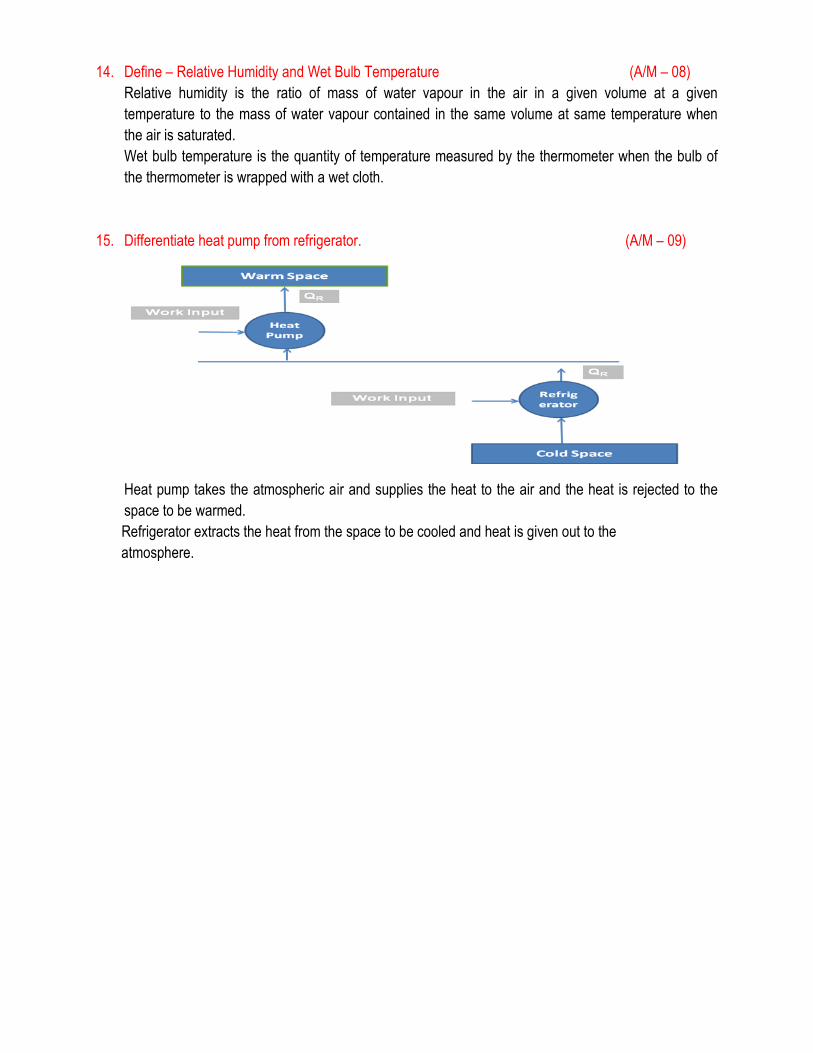
15. Differentiate heat pump from refrigerator. (A/M – 09)
Heat pump takes the atmospheric air and supplies the heat to the air and the heat is rejected to the
space to be warmed.
Refrigerator extracts the heat from the space to be cooled and heat is given out to the
atmosphere.
Part – B (16 Marks)
1. Explain the working principle of vapour compression refrigeration cycle with neat sketch.
2. Explain the working principle of vapour absorption refrigeration cycle with neat sketch.
3. A refrigeration machine is required to produce i.e., at 0°C from water at 20°C. The machine has a condenser temperature of 298 K while the evaporator temperature is 268 K. The relative efficiency of the machine is 50% and 6 kg of Freon-12 refrigerant is circulated through the system per minute. The refrigerant enters the compressor with a dryness fraction of 0.6. Specific heat of water is 4.187 kJ/kg K and the latent heat of ice is 335 kJ/kg. Calculate the amount of ice produced on 24 hours. The table of properties of Freon-12 is given below :
4. 28 tonnes of ice from and at 0°C is produced per day in an ammonia refrigerator. The temperature range in the compressor is from 25°C to – 15°C. The vapour is dry and saturated at the end of compression and an expansion valve is used. Assuming a co-efficient of performance of 62% of the theoretical, calculate the power required to drive the compressor.
5. Explain various types of air conditioning systems with neat sketch.
6. Explain various psychrometric processes with the help of psychrometric chart.
7. The sling psychrometer in a laboratory test recorded the following readings : Dry bulb temperature = 35°C Wet bulb temperature = 25°CAtmospheric pressure = 1.0132 barCalculate, (i) Specific humidity, (ii) Relative humidity, (iii) Vapour density in air, (iv) Dew point temperature and (v) Enthalpy of mixture per kg of dry air.
8. An air-water vapour mixture enters an air-conditioning unit at a pressure of 1.0 bar. 38°C DBT, and a relative humidity of 75%. The mass of dry air entering is 1 kg/s. The air-vapour mixture leaves the air-conditioning unit at 1.0 bar, 18°C, 85% relative humidity. The moisture condensed leaves at 18°C. Determine the heat transfer rate for the process.
9. Saturated air at 3ºC is required to be supplied to a room where the temperature must be held at 22ºC with a relative humidity of 55%. The air is heated and then water at 10ºC is sprayed to give the required humidity. Determine, (i) The mass of spray water required per m3 of air at room conditions.
10. A small-size cooling tower is designed to cool 5.5 litres of water per second, the inlet temperature of which is 44ºC. The motor-driven fan induces 9 m3/s of air through the tower and the power absorbed is 4.75 kW. The air entering the tower is at 18ºC, and has a relative humidity of 60%. The air leaving the tower can be assumed to be saturated and its temperature is 26ºC. Calculate, (i) The amount of cooling water (make-up) required per second. (ii) The final temperature of the water. Assume that the pressure remains constant throughout the tower at 1.013 bar.
11. An ammonia refrigerator produces 30 tons of ice at 0oC in a day of 24 hours. The temperature
range in the compressor is from 25o C to -15oC. The vapour is dry saturated at the end of
compression. Assume a COP of 60 % of theoretical value. Find power required to drive
compressor. Assume latent heat of ice is 335 kJ/kg. For properties of ammonia refer table below:
(AU May 2013)
12. (a) An office is to be air- conditioned for 50 staff when the outdoor conditions are 30o C DBT and 75% RH if the quantity of air supplied is 0.4 m3/ min / person, find the following: (i) Capacity of the cooling coil in tones of refrigeration, (ii) Capacity of the heating coil in kW, (iii) Amount of water vapour removed per hour. Assume that required inlet conditions are 200 C DBT and 60% RH. Air is first conditioned by cooling and dehumidifying and then by heating. (12)
(b) Describe the factors that affect human comfort. (4) (AU May 2013)
13. The temperature limits of an ammonia refrigeration system are 25o C and -10oC. If the gas is dry at
the end of compression , Calculate the COP assumi8ng no-under cooling of the system. The
properties of ammonia are given below. (AU Nov .2013)
14. Explain briefly various absorption system, and give the comparison vapour compression system
and vapour absorption system. (AU May/ June 2014)