dhanalakshmi college of engineering - dce 6512-sc-iii-qb.pdf · dhanalakshmi college of engineering...
TRANSCRIPT
DHANALAKSHMI COLLEGE OF ENGINEERING Manimangalam, Tambaram, Chennai –601 301
DEPARTMENT OF
CIVIL ENGINEERING
CE 6512 - SURVEY CAMP
V SEMESTER R 2013
Name :
Register. No. :
Class :
LABORATORY MANUAL MMMMmMANUALMANUAL

1 Format No.:DCE/Stud/LP/34/Issue : 00/Revision : 00
DHANALAKSHMI COLLEGE OF ENGINEERING
Dhanalakshmi College of Engineering is committed to provide highly disciplined, conscientious and
enterprising professionals conforming to global standards through value based quality education and training.
To provide competent technical manpower capable of meeting requirements of the industry
To contribute to the promotion of Academic Excellence in pursuit of Technical Education at different levels
To train the students to sell his brawn and brain to the highest bidder but to never put a price tag on heart
and soul
DEPARTMENT OF CIVIL ENGINEERING
To impart professional education integrated with human values to the younger generation, so as to
shape them as proficient and dedicated engineers, capable of providing comprehensive solutions to the
challenges in deploying technology for the service of humanity
To educate the students with the state-of-art technologies to meet the growing challenges of the civil industry
To carry out research through continuous interaction with research institutes and industry, on advances in
structural systems
To provide the students with strong ground rules to facilitate them for systematic learning, innovation and
ethical practices
VISION
VISION
MISSION
MISSION
2 Format No.:DCE/Stud/LP/34/Issue : 00/Revision : 00
PROGRAMME EDUCATIONAL OBJECTIVES (PEOs)
1. Fundamentals
To provide students with a solid foundation in Mathematics, Science and fundamentals of
engineering, enabling them to apply, to find solutions for engineering problems and use this knowledge to
acquire higher education
2. Core Competence
To train the students in Civil Engineering technologies so that they apply their knowledge and
training to compare, and to analyze various engineering industrial problems to find solutions
3. Breadth
To provide relevant training and experience to bridge the gap between theory and practice which
enables them to find solutions for the real time problems in industry, and to design products?
4. Professionalism
To inculcate professional and effective communication skills, leadership qualities and team spirit in
the students to make them multi-faceted personalities and develop their ability to relate engineering issues to
broader social context
5. Lifelong Learning/Ethics
To demonstrate and practice ethical and professional responsibilities in the industry and society in
the large, through commitment and lifelong learning needed for successful professional career

3 Format No.:DCE/Stud/LP/34/Issue : 00/Revision : 00
PROGRAMME OUTCOMES (POs)
a) Underscoring the importance of technical education (markedly civil engineering education) in the infrastructural
development of a country as a whole, Institute of Engineering has aimed to provide quality engineering education in
civil engineering.
b) This program has been serving through its product in different parts of the country ranging from the gamut of remote
and mountainous areas to the southern plains of Nepal.
c) Regarding civil engineering education, survey course comprises the core of this education program.
d) Survey course is required from the very preliminary study stage to construction stages. Developing country like Nepal
requires manpower of interdisciplinary expertise to accomplish project independently.
e) Institute of engineering has given significant importance to the field oriented subject like surveying. Regarding
surveying, conventional surveying has been replaced by modern computerized high-tech survey equipments.
f) With the viewpoint to enhance survey course, Institute of Engineering provided sufficient number of modern
equipments such as total stations with survey software.
g) At present state, although survey course is equipped with modern technologies,
h) Doubt still arises regarding its better use and execution, cost-effectiveness, quality and sustainability.
i) Since the success of surveying course depends upon its quality and better performance, this paper aims at providing
suggestions and recommendations regarding the proper formulation of Survey Camp guide.

4 Format No.:DCE/Stud/LP/34/Issue : 00/Revision : 00
CE 6512 – SURVEY CAMP
SYLLABUS
To acquire practical knowledge on handling basic chain survey equipments
To possess knowledge about compass surveying
To have the ability to prepare leveling table
To possess knowledge about contour map
LIST OF EXPERIMENTS
1. Determination of area by triangulation method
2. Determination of area by trilateration method
3. Grid contouring
4. Radial contouring
5. Check leveling
6. Levelling – CS and LS
7. Plane table surveying radiation method
8. Area calculation by using total station.
Students completing this course would have acquired practical knowledge on handling survey instruments
like Theodolite, Tacheometery and Total station and have adequate knowledge to carryout Triangulation and
Astronomical surveying including general field marking for various engineering projects and curves setting.
COURSE OBJECTIVES
COURSE OUTCOMES

5 Format No.:DCE/Stud/LP/34/Issue : 00/Revision : 00
CE6512 – SURVEY CAMP
CONTENTS
Sl.No. Name of the Experiment Page No.
CYCLE 1 – EXPERIMENTS
1 Determination of area by triangulation method 7
2 Determination of area by trilateration method 13
3 Grid contouring 19
4 Radial contouring 24
5 Check leveling 28
CYCLE 2 – EXPERIMENTS
6 Levelling – CS and LS 35
7 Plane table surveying radiation method 38
8 Plane table surveying traversing method 38
9 Area calculation by using total station. 41
6 Format No.:DCE/Stud/LP/34/Issue : 00/Revision : 00
Expt. No. 01 DETERMINATION OF AREA BY TRIANGULATION
METHOD
Aim:
To determine the area of the given plot using the method of triangulation
Instruments required:
Theodolite with tripod stand
Ranging rod
Tape
Arrow
Theory:
Triangulation is the process of establishing horizontal control in the surveying. The triangulation system
consists of number of inter connected triangles in which the length of the base line and the triangle are measured
very precisely.
Diagram:

7 Format No.:DCE/Stud/LP/34/Issue : 00/Revision : 00
Procedure:
Select the base line and mark as P and Q at 25m distance apart.
Select the other station points namely A,B,C,D around the base line PQ
Fix the ranging rods at each point and now the instrument is placed over the station P and all other
adjustments are made.
Then from P the ranging rod at the station Q is sighted and angles were noted keeping the instrument.
At face left similarly from station P sight all the other points and the angles were measured. After that the
angles were noted by changing the face of the instrument to face right.
Shift the instrument to station Q and the initial adjustments are done.
Repeat the same procedure carried out at the station P and the angles were recorded.
From P the ranging rod at the station Q is sighted and angles were noted keeping the instrument.
At face left similarly from station P sight all the other points and the angles were measured. After that the
angles were noted by changing the face of the instrument to face right.
Calculate the interior angles and drawings are drawn. Area are calculated using the formula
Formulae:

8 Format No.:DCE/Stud/LP/34/Issue : 00/Revision : 00
For calculating the sides of a triangle,
AB2 = AC2 + BC2 – 2*AC*BC*cosθ
θ is the angle between ACB
Area:
A=√ ( )( )( )
s =( )
,
Where,
a, b and c are sides of a triangle
9 Format No.:DCE/Stud/LP/34/Issue : 00/Revision : 00
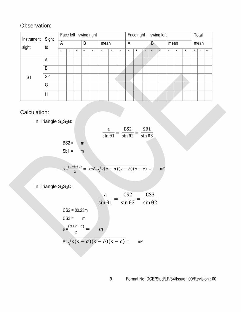
Observation:
Instrument
sight
Sight
to
Face left swing right Face right swing left Total
mean A B mean A B mean
* ‘ ‘’ “ ‘ “ * ‘ “ * ‘ “ * ‘ “ * * ‘ “
S1
A
B
S2
G
H
Calculation:
In Triangle S1S2B:
BS2 = m
Sb1 = m
s =( )
A=√ ( )( )( ) = m2
In Triangle S2S3C:
CS2 = 80.23m
CS3 = m
s =( )
A=√ ( )( )( ) = m2
10 Format No.:DCE/Stud/LP/34/Issue : 00/Revision : 00
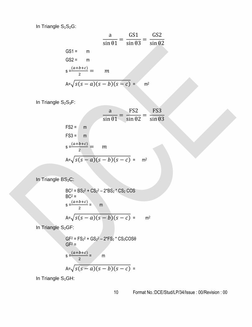
In Triangle S1S2G:
GS1 = m
GS2 = m
s =( )
A=√ ( )( )( ) = m2
In Triangle S2S3F:
FS2 = m
FS3 = m
s =( )
A=√ ( )( )( ) = m2
In Triangle BS2C: BC2 = BS2
2 + CS22 – 2*BS2 * CS2 COS
BC2 =
s =( )
= m
A=√ ( )( )( ) = m2
In Triangle S2GF: GF2 = FS2
2 + GS22 – 2*FS2 * CS2COSθ
GF2 =
s =( )
= m
A=√ ( )( )( ) =
In Triangle S1GH:
11 Format No.:DCE/Stud/LP/34/Issue : 00/Revision : 00
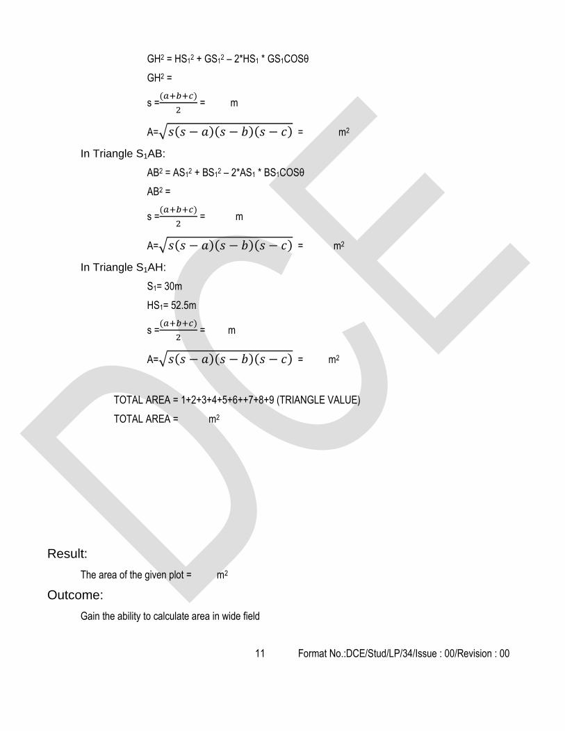
GH2 = HS12 + GS1
2 – 2*HS1 * GS1COSθ
GH2 =
s =( )
= m
A=√ ( )( )( ) = m2
In Triangle S1AB:
AB2 = AS12 + BS1
2 – 2*AS1 * BS1COSθ
AB2 =
s =( )
= m
A=√ ( )( )( ) = m2
In Triangle S1AH:
S1= 30m
HS1= 52.5m
s =( )
= m
A=√ ( )( )( ) = m2
TOTAL AREA = 1+2+3+4+5+6++7+8+9 (TRIANGLE VALUE)
TOTAL AREA = m2
Result:
The area of the given plot = m2
Outcome:
Gain the ability to calculate area in wide field

12 Format No.:DCE/Stud/LP/34/Issue : 00/Revision : 00
1. What is surveying?
2. What are the types of surveying? What are the primary divisions of surveying?
3. What are the types of ranging?
4. What is meant by tie stations
5. What are check lines?
6. What are the uses of contours?
7. What is different between fore bearing and back bearing?
8. What is meant by well-conditioned triangle?
9. How will you test a chain?
10. Differentiate metric chain from engineer's chains.
11. What is meant by reconnaissance survey?
12. What is representative fraction?
13. What is meant by scale of plan?
14. What is a well conditional triangle?
15. What do you mean by scale in surveying?
Optical 3D measuring systems use this principle as well in order to determine the spatial dimensions and the
geometry of an item
Viva-voce
Applications

13 Format No.:DCE/Stud/LP/34/Issue : 00/Revision : 00
Expt. No. 02 DETERMINATION OF AREA BY TRILATERATION
METHOD
Aim:
To determine the distance between the given station points using the method of trilateration and area
enclosed by the station points
Instruments required:
Theodolite
Ranging rod
Leveling staff
Cross staff
Arrows
Pegs
Theory:
Trilateration is the method of calculating the distance between the station points by running a closed traverse
Diagram:

14 Format No.:DCE/Stud/LP/34/Issue : 00/Revision : 00
Procedure:
Mark the given points A, B, C, D, E by using peg or arrows in such a way that it is possible to see those
points from any point
Place the instrument in such a way that it is centre to all the points and also visible from the selected points.
The initial adjustment are done for accuracy in the survey
Then the point A is forced and then the vertical angle and the top, middle and top hair readings are taken by
placing the leveling staff at point A.
Take the vertical and the top, middle and the top hair reading for all the given points.
Then the instrument is set any point and the distance and the vertical angle between the adjacent points are
taken.
Thus we get a polygon whose sides are known or multiple triangle whose sides are drawn
By using the given dimensions and by using the triangle formulas the area can be calculated
Formula used:
Horizontal distance
D = KS COS2θ + C COSθ
K = multiple constants =100
C= additive constants = 0
S = staff intercept (top hair – bottom hair)
Area Of The Triangle:
A=√ ( )( )( )
s =( )
,
Where,
a, b and c are sides of a triangle
Observation:
Horizontal distance = KS COS2θ + C COSθ
Where C=0
OA = KS COS2θ + C COSθ

15 Format No.:DCE/Stud/LP/34/Issue : 00/Revision : 00
STATION PT SIGHT
TO
STADIA HAIR READING VERTICAL
POINT VERTICAL ANGLE
TOP MIDDLE BOTTOM
O
A
B
C
D
E
F
A B
F
E D
F
C D
B
Calculation:
OC = KS COS2θ + C COSθ
OC=
OD = KS COS2θ + C COSθ
OD=
OE = KS COS2θ + C COSθ
OE=
OF= KS COS2θ + C COSθ
OF=
AB= KS COS2θ + C COSθ
AF = KS COS2θ + C COSθ
AF=
ED = KS COS2θ + C COSθ
ED=

16 Format No.:DCE/Stud/LP/34/Issue : 00/Revision : 00
EF = KS COS2θ + C COSθ
EF =
CD = KS COS2θ + C COSθ
CD=
CB = KS COS2θ + C COSθ
CB=
To find the area:
In Triangle AOB:
A=√ ( )( )( ) =
= ( )
=
In Triangle BOC:
A=√ ( )( )( ) =
s =( )
=
In Triangle COD:
A=√ ( )( )( ) =
s =( )
=
In Triangle DOE:
A=√ ( )( )( ) =
s =( )
=
In Triangle EOF:
A=√ ( )( )( ) =
s =( )
=
In Triangle AOF:
A=√ ( )( )( ) =

17 Format No.:DCE/Stud/LP/34/Issue : 00/Revision : 00
s =( )
=
TOATAL AREA = A1 +A2 + A3 + A4+ A5 +A6
A=
Result:
The area of the given plot is m2
Outcome:
Gain the ability to calculate area in wide field

18 Format No.:DCE/Stud/LP/34/Issue : 00/Revision : 00
1. What are optical square?
2. What are the well-conditioned and ill conditioned triangles?
3. Mention different types of compasses?
4. What is meant by ranging
5. What is theodolite?
6. What is change point?
7. What is profile levelling?
8. What are the major parts of a theodolite?
9. What do you mean by latitude and departure in a theodolite traversing?
10. What is mean by parallax?
11. Name the temporary adjustments in a transit.
12. Define the term “transiting of telescope”.
13. What are the various methods of balancing a traverse?
14. State the location and function of a plate bubble in a theodolite.
15. What are latitude and departure? What are their sign conventions?
Trilateration does have practical applications in surveying and navigation, including global
positioning systems (GPS).
Viva-voce
Applications

19 Format No.:DCE/Stud/LP/34/Issue : 00/Revision : 00
Expt. No. 03 GRID CONTOURING
Aim:
To draw the contour map for the given area
Instruments required:
Theodolite with tripod stand
Ranging rod
Leveling staff
Arrows
Cross staff
Tape or chain
Theory:
A map without relief representation is simply a plan on which relative positions of details are only shown in
horizontal phase. Relative heights of various points on the map may be represented by one of the methods of
contour
Diagram:

20 Format No.:DCE/Stud/LP/34/Issue : 00/Revision : 00
Procedure:
The site for block countouring is selected by through study. The dimension of block counter size is selected
accordingly.
Then the area is divided into blocks of the size 3m*3m by using cross staff, chain and ranging rod.
The instrument is placed in such a place where maximum reading can be taken on the intersection points
Change points are provided wherever needed. After taking the readings, the RL of each point is calculated by height of
collimation method or by rise and fall method.
All reduced levels are plotted in A2 drawing sheet of suitable scale.
Observation:
STATION X Y B.S I.S F.S H.I R.L REMARKS
0,0 0 0
5,0 5 0
10,0 10 0
15,0 15 0
20,0 20 0
25,0 25 0
30,0 30 0
0,5 0 5
5,5 5 5
10,5 10 5
15,5 15 5
20,5 20 5
25,5 25 5
30,5 30 5
0,10 0 10
5,10 5 10
10,10 10 10
15,10 15 10
20,10 20 10
21 Format No.:DCE/Stud/LP/34/Issue : 00/Revision : 00
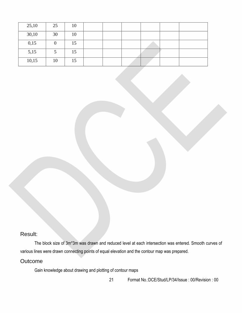
25,10 25 10
30,10 30 10
0,15 0 15
5,15 5 15
10,15 10 15
Result:
The block size of 3m*3m was drawn and reduced level at each intersection was entered. Smooth curves of
various lines were drawn connecting points of equal elevation and the contour map was prepared.
Outcome
Gain knowledge about drawing and plotting of contour maps

22 Format No.:DCE/Stud/LP/34/Issue : 00/Revision : 00
1. What is surveyor chain?
2. What are the types of bearing and meridian
3. What are errors in chaining?
4. What are errors in chaining?
5. What are the different types of chain?
6. What is dip?
7. How can you eliminate the dip?
8. What are thedifferent types of bench marks.
9. What is “Contour interval” and “horizontal equivalent”?
10. What is profile leveling? State its application.
11. Why the necessity of making, balancing of backsights and foresights.
12. What are the various methods of booking a reduced level?
13. What is meant by the term contour gradient?
14. What are the different types of leveling staves?
15. What is horizontal equivalent? Why is it constant?
1. The nature of the ground and its slope can be estimated
2. Earth work can be estimated for civil engineering projects like road works, railway, canals, dams etc.
Viva-voce
Applications

23 Format No.:DCE/Stud/LP/34/Issue : 00/Revision : 00
Expt. No: 04 RADIAL CONTOURING
Aim:
To prepare contour map for the given area
Instruments required:
Theodolite
Ranging rod
Chains
Arrows
Pegs
Diagram:
Theory:
This method is suitable for countering the area of long strip undulations where direct chaining is difficult.
Procedure:
Range out the radial line from a common centre at known angular interval.
Fix arrows on the radial lines at equal distances of 3m or 5m.
24 Format No.:DCE/Stud/LP/34/Issue : 00/Revision : 00
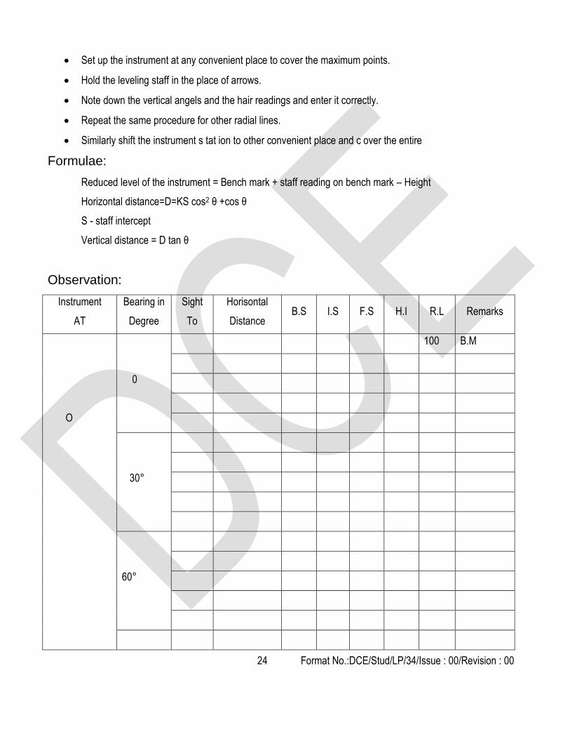
Set up the instrument at any convenient place to cover the maximum points.
Hold the leveling staff in the place of arrows.
Note down the vertical angels and the hair readings and enter it correctly.
Repeat the same procedure for other radial lines.
Similarly shift the instrument s tat ion to other convenient place and c over the entire
Formulae:
Reduced level of the instrument = Bench mark + staff reading on bench mark – Height
Horizontal distance=D=KS cos2 θ +cos θ
S - staff intercept
Vertical distance = D tan θ
Observation:
Instrument
AT
Bearing in
Degree
Sight
To
Horisontal
Distance B.S I.S F.S H.I R.L Remarks
O
0
100 B.M
30°
60°

25 Format No.:DCE/Stud/LP/34/Issue : 00/Revision : 00
O
90°
120°
Result:
The block size of 3mx3m was drawn and reduced level at each intersection was entered. Smooth curves of
various lines were drawn connecting point of equal elevation and the contour map was prepared.
Outcome:
Gain knowledge about drawing and plotting of contour maps

26 Format No.:DCE/Stud/LP/34/Issue : 00/Revision : 00
1. What is local attraction?
2. How local attraction can be detected?
3. What are the types of traverse?
4. What is meant by variation of declinations
5. What is different between magnetic bearing and true bearing?
6. What are the objects of preparing a contour map?
7. What is meant by contour gradient? Where it is used?
8. In some, contour lines are closer. In some, they are wide for the same contour interval. What does it mean?
9. Why the horizontal equivalent is not constant?
10. How to calculate earthwork using contours?
11. How will you differentiate a summit from a depression by studying the nature of the contour?
12. What is meant by Contour Line?
13. What is Contour Interval?
14. What is meant by Horizontal Equivalent?
15. What are the different types of Bench marks?
1. It is possible to identify suitable site for any project from the contour map of the region.
2. Inter-visibility of points can be ascertained using contour maps. This is most useful for locating
communication towers.
Viva-voce
Applications

27 Format No.:DCE/Stud/LP/34/Issue : 00/Revision : 00
Expt. No.05 CHECK LEVELLING
Aim:
To run the check level to find the level difference of the given points
Apparatus required:
Dumpy level
Tripod
Staff
Diagram:
Procedure:
1. Set up the instrument at P to cover the maximum points
2. Do all the initial adjustments
3. Direct the telescope towards the first point and enter the reading as B.S.
4. Enter the reading of the last visible point from the instrument station as F.S. and of all other point as I.S.
5. Shift the instrument to Q, set up and level it correctly.
6. Don’t change the position of the staff until the back staff reading is taken on the staff held at the last required
point.
7. Do the same procedure in the reverse direction and close with the first point

28 Format No.:DCE/Stud/LP/34/Issue : 00/Revision : 00
Formulae:
∑B.S - ∑ F.S = Last RL – First R
Observation:
Reduced level of the first point =
Result:
Closing error =
R.L. for the given points =
Outcome:
Knowing error rectify technique about field measurement values
Staff station B.S I.S F.S H.I R.L Remarks

29 Format No.:DCE/Stud/LP/34/Issue : 00/Revision : 00
1. What are the types of traverse?
2. What are variation of declinations
3. What is different between magnetic bearing and true bearing?
4. What is plane tabling?
5. Mention the suitability and unsuitability of plane tabling?
6. What is levelling?
7. How leveling is done using foot screws?
8. What is fly levelling?
9. Name the different types of bench marks.
10. What are the different types of leveling staves?
11. What is horizontal equivalent? Why is it constant?
12. What is fore sight?
13. What is back sight?
14. What is change point?
15. What is profile levelling?
It is the operation of running levels for the purpose of checking the series of levels, which have been previously
fixed. At the end of each day’s work, a line of level is run, returning to the starting point of that day with a view to
check the work done on that day.
Viva-voce
Applications

30 Format No.:DCE/Stud/LP/34/Issue : 00/Revision : 00
Expt. No. 06 LEVELLING - LONGITUDINALSECTIONING AND
CROSS SECTIONING
Aim:
To plot the profile of the longitudinal and cross section for an existing road, embankment, etc
Instruments required:
Level with tripod
Ranging rods
Leveling staff
Chain
Cross staff
Arrows
Pegs.
Procedure (Longitudinal sectioning):
Fix the centre line by ranging and chaining.
Set up the instrument at suitable position and do all the initial adjustments.
Place the staff at frequent intervals over the central line (say 5m) and enter the readings correctly.
Set the bubble for its centre of run at each and every point.
If necessary, shift the instrument to some other place and take B.S as well as F.S. at change points.
Do the calibration to find the R.L. for different points.
Observation:
Longitudinal sectioning:
Reduced level of the first point =…………………..
Staff station Distance B.S I.S F.S H.I R.L Remarks

31 Format No.:DCE/Stud/LP/34/Issue : 00/Revision : 00
Graph:
Procedure (Cross sectioning):
Align the centre of the bund using ranging and chaining.
Fix the longitudinal intervals along the central line depending upon the nature of ground (say 5 or 10m) and
let it be C1,C2,C3……….Cn
At each longitudinal interval fix cross section intervals perpendicular to the centre line using cross staff or
optical square to a suitable distance depending upon the nature of slope of the bund (say 1 to 5m) on each
side.
Set up the instrument at a suitable position the mostlowest point and most highest point can be focused.
Do all the initial adjustments.
Turn the telescope and note down the readings as follows
The readings along the centre of the bund is recorded as C1,C2,C3………Cn.
The readings taken on right side of the centre line is recorded as R1,R2,R3…….Rn and the left side as
L1,L2,L3….Ln.
Shift the instrument if necessary to some other place. Put change the point and repeat the above procedure.
Find the R.L for each and every point by any one of the method.

32 Format No.:DCE/Stud/LP/34/Issue : 00/Revision : 00
Observation:
Cross sectioning:
Reduced level of the first point =…………………..
Result:
1. The longitudinal and cross section of the given road is thus plotted.
2. Volume of the earth work estimated = ……………….
Outcome
Gain the ability to plot the longitudinal and cross section of roads
Staff
station
Distance B.S I.S F.S H.I R.L Remarks
Left centre right

33 Format No.:DCE/Stud/LP/34/Issue : 00/Revision : 00
1. What is meant by leveling?
2. What is the principle of leveling?
3. What are the types of level?
4. What are the major parts of theodolite?
5. What is Transiting of Telescope?
6. What is face right observations?
7. What is meant by transit?
8. What are the uses of tangential screw provided for the adjustments in a transit theodolite?
9. Write short notes on face left and face right of the theodolite.
10. List out the essential qualities of a theodolite telescope.
11. What is meant by parallax?
12. What is centering of a theodolite?
13. What are the methods to be used in measuring horizontal angles using theodolite?
1. Longitudinal sections of ground level in road and sewer construction
2. Headroom of bridges and slabs (Clear height)
3. Formation of Contours
Viva-voce
Applications

34 Format No.:DCE/Stud/LP/34/Issue : 00/Revision : 00
Expt. No. 07 PLANE TABLE SURVEYING RADIATION METHOD
Aim:
To locate the object from a single station and to find the area of the given polygon
Instruments Required:
Plane table with stand
Tape
Trough compass
Alidade
Spirit level
Plumbing fork with plumb bob
Arrows
Ranging rod and
Measuring.
Diagram:
Theory:
When from a single set of plane table on instrument station different details are located on the sheet, the
method is known as radiation method In this method the rays are drawn from the instrument station to the point to be
located, then the distances are measured from the instruments station to the point and the position of the each point
is plotted on the sheet using a suitable scale.

35 Format No.:DCE/Stud/LP/34/Issue : 00/Revision : 00
Procedure:
Select the position of the table where it is be set so that all the points to be located are visible from it. Let ’O’
be the position of such a point on the ground.
Set the plane table over this point and level it. Draw the North line in the top corner of sheet by means of
trough compass at the table.
Draw the ray along the fiducial edge. Measure the distance of this point from the instrument station by
means of tape and plot the point ‘a’ corresponding to point ‘A’ in the field to scale in the sheet.
Similarly sight other points such as B, C, D, E etc. and measure their distances from the instrument station.
Plot them to scale to get their position on the sheet such as b, c, d etc. on the sheet.
Now transfer the position of the point ‘O’ on the ground to the sheet by means of the plumbing fork. The point
‘O’ will represent point ‘o’ will represent point ‘O’on the ground.
Calculations:
The outline of the profile is plotted as shown= ))()(( csbsass
S =
Result:
The object from a single station where located and the enclosed area of the given polygon is calculated.
Area of the polygon ABCDE =
Outcome:
Understood the field computations and measurements.
36 Format No.:DCE/Stud/LP/34/Issue : 00/Revision : 00
1. What are the equipments used in plane tabling?
2. What are the methods of plane tabling?
3. What is leveling?
4. What is the principle of leveling?
5. Mention the types of level.
6. What are vertical controls in setting out works?
7. What are transition curves?
8. Draw a neat sketch showing a simple circular curve and show essential notations.
9. What are the various special conditions confronted in the underground surveys?
10. What is the versed sine of a curved? Express it mathematically.
11. What is mass diagram? Why it is prepared?
12. What is tangent length in a simple curve?
13. What is mid-ordinate in a simple curve?
14. What are the two instruments used for mine surveying
15. How leveling is done using foot screws?
1. Plane Table Surveying is a graphical method of surveying which the field observations and plotting are done
simultaneously.
2. It is simple and cheaper than theodolite survey. It is most suitable for small scale maps.
Viva-voce
Applications
37 Format No.:DCE/Stud/LP/34/Issue : 00/Revision : 00
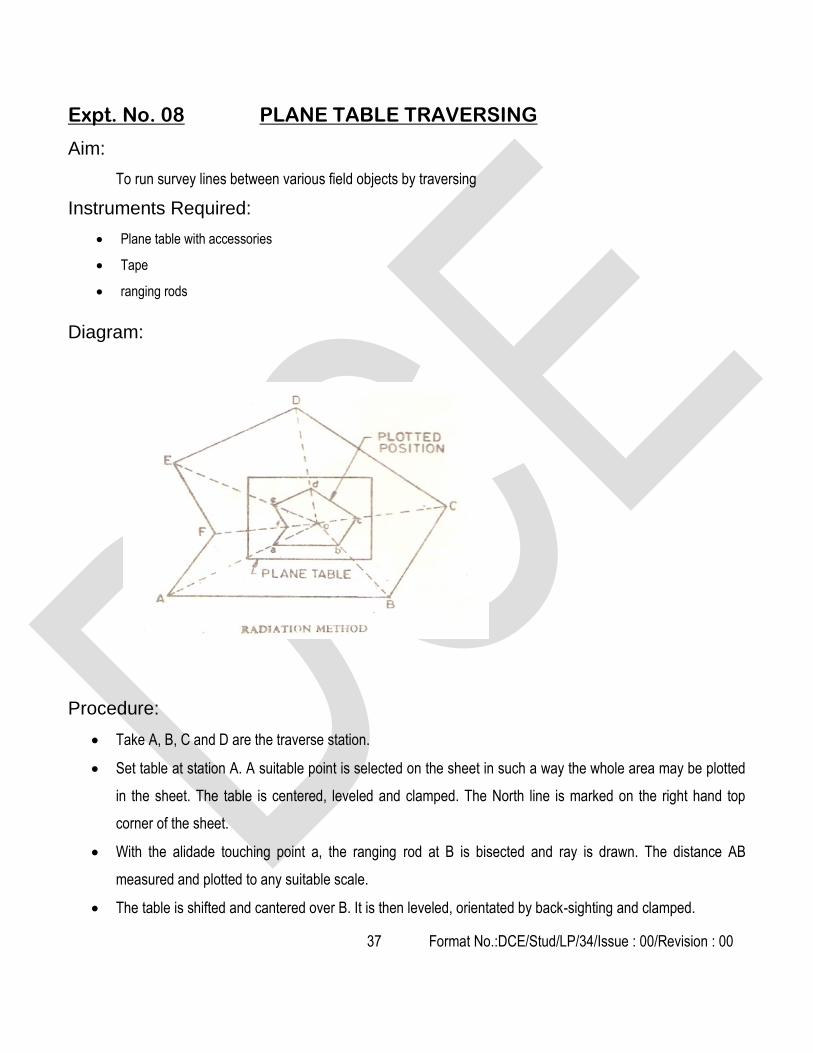
Expt. No. 08 PLANE TABLE TRAVERSING
Aim:
To run survey lines between various field objects by traversing
Instruments Required:
Plane table with accessories
Tape
ranging rods
Diagram:
Procedure:
Take A, B, C and D are the traverse station.
Set table at station A. A suitable point is selected on the sheet in such a way the whole area may be plotted
in the sheet. The table is centered, leveled and clamped. The North line is marked on the right hand top
corner of the sheet.
With the alidade touching point a, the ranging rod at B is bisected and ray is drawn. The distance AB
measured and plotted to any suitable scale.
The table is shifted and cantered over B. It is then leveled, orientated by back-sighting and clamped.

38 Format No.:DCE/Stud/LP/34/Issue : 00/Revision : 00
With the alidade touching point b, the ranging rod at C is bisected and a ray is drawn. The distance BC is
measured and plotted to the same scale.
The table is shifted and setup at C and the same procedure is repeated for all stations.
In this manner, all station of traverse are connected
At the end, the finishing point may not coincide with the starting point and there may be some closing error
.This error is adjusted graphically by Bowditch’s rule.
Result:
The area of the given traverse is = ………………..
Outcome:
Knowing position information for property and structure

39 Format No.:DCE/Stud/LP/34/Issue : 00/Revision : 00
1. What are the accessories of plane tabling?
2. Mention the types of leveling staves.
3. What are back sights and fore sights?
4. What is the height of instrument?
5. What is meant by intermediate sight?
6. What are the temporary adjustments of leveling?
7. What are the disadvantages of plane table surveying?
8. Write the advantages of plane table surveying?
9. Differentiate Prismatic compass from Surveyor's compass with reference to reading as well as tripod.
10. What are the errors in a compass instrument?
11. What is true meridian?
12. What is true bearing?
13. What is orientation? Why it is to be performed?
14. What is orientation? Why is it done?
15. What is magnetic meridian?
1. Traverse is a method in the field of surveying to establish control networks.
2. It is also used in geodesy.
3. Traverse networks involve placing survey stations along a line or path of travel, and then using the
previously surveyed points as a base for observing the next point.
Viva-voce
Applications

40 Format No.:DCE/Stud/LP/34/Issue : 00/Revision : 00
Expt. No. 09 AREA CALCULATION BY USING TOTAL STATION
Aim:
Measure the area of given boundary points by using Total Station.
Apparatus Required:
Total Station and tripod
Prism and prism rod
Arrows
Diagram:
Procedure:
Set the instrument at the station point which the point covers all boundary points.
Do the temporary adjustments in the instrument and level it properly.
Set the prism height and enter the prism height value in Total Station.
Consider all boundary points in closed traverse.
Select the area measurement option and bisect the boundary points with the help of prism.
Take readings from all boundary points and directly found the area from Total Station.

41 Format No.:DCE/Stud/LP/34/Issue : 00/Revision : 00
Result:
The area of the given field = -------------- measured by Total Station.
Outcome
Gain the ability to use modern survey equipment to measure angle and distance.
1. What is meant by Contour Gradient?
2. What are the classification of Total station?
3. What are the different methods of contouring?
4. What are LS and CS?
5. What are the parts of total station?
6. What is meant by vertical axis?
7. What is meant by Horizontal axis?
8. What is meant by line of sight / line of collimation?
9. What is meant by axis of level tube?
10. What is meant by centering?
11. What is meant by transiting?
12. What is meant by swinging the telescope?
13. What is meant by telescope normal?
14. What is meant by telescope inverted?
15. What is meant by changing face?
1. A total station is an electronic/optical instrument used in modern surveying.
2. The total station is an electronic theodolite (transit) integrated with an electronic distance meter (EDM), plus
internal data storage and/or external data collector.
Viva-voce
Applications