development of walk safe cane for the rehabilitaion...
TRANSCRIPT
DEVELOPMENT OF WALK SAFE CANE FOR THE REHABILITAION
OF BLIND PEOPLE
A THESIS SUBMITTED IN PARTIAL FULFILLMENT
OF THE REQUIREMENTS FOR THE DEGREE OF
BACHELOR OF TECHNOLOGY
IN
BIO-MEDICAL ENGINEERING
SUBMITTED BY
KRISHNA KUMAR
110BM0007
UNDER THE GUIDANCE OF
Dr. KUNAL PAL
DEPARTMENT OF BIOTECHNOLOGY AND MEDICAL ENGINEEIRNG
NATIONAL INSTITUTE OF TECHNOLOGY
ROURKELA-769008
1
DEPARTMENT OF BIOTECHNOLOGY & MEDICAL ENGINEERING,
NATIONAL INSTITUTE OF TECHNOLOGY-ROURKELA
Dated: 12th
May, 2014
CERTIFICATE
This is to certify that the thesis entitled “DEVELOPMENT OF WALK SAFE CANE(WSC)
FOR THE REHABILITAION OF BLIND PEOPLE” submitted by Mr. Krishna Kumar in
partial fulfillment for the requirements for the award of Bachelor of Technology Degree in
Biotechnology at National Institute of Technology, Rourkela is an authentic work carried out by
him under the supervision of the undersigned.
To the best of my knowledge, the matter embodied in the thesis has not been submitted to any
other University / Institute for the award of any Degree or Diploma.
(Dr. KUNAL PAL) Assistant Professor
2
ACKNOWLEDGEMENTS
I would like to express my deep sense of gratitude and respect to our supervisor, Dr. Kunal Pal,
Assistant Professor, Department of Biotechnology and medical Engineering, National Institute of
Technology Rourkela for his excellent guidance, suggestions and constructive criticism. He has
been very kind, supportive and patient to me while suggesting the outlines of the project and has
also been very helpful in the successful completion of the same. I thank him for his overall
support.
Last but not the least; I would like to extend my heartfelt gratitude to the Ph.D and M.Tech
scholars, Department of Biotechnology and Medical Engineering, National Institute of
Technology, Rourkela for their support and guidance. Their helping nature and suggestion has
helped me to complete this present work.
I am really thankful to National Institute of Technology, Rourkela, for permitting me to
utilise the facilities in its laboratories for the smooth execution of my experiment.
I extend my warm gratitude to my friends, Mr. Dablu Ranjan and Mr. Ripunjay Chachan, for
their constant motivation and support throughout the course of my B.Tech research. Finally, I
would like to thank my seniors, juniors and my fellow students who enthusiastically
supported me by providing the necessary data walking blindfolded.
Date: Krishna Kumar
3
CONTENTS
ABBREVIATIONS ...................................................................................................................................... 4
LIST OF TABLES ........................................................................................................................................ 5
LIST OF FIGURES ...................................................................................................................................... 6
ABSTRACT .................................................................................................................................................. 7
1. INTRODUCTION .................................................................................................................................... 9
2. LITERATURE REVIEW ....................................................................................................................... 11
3. MATERIALS AND METHODS ............................................................................................................ 15
3.1. MATERIALS ....................................................................................................................................... 15
3.2. METHODS ......................................................................................................................................... 19
4. RESULTS AND DISCUSSIONS ....................................................................................................... 25
5. CONCLUSION ....................................................................................................................................... 28
REFERENCES ........................................................................................................................................... 30
4
ABBREVIATIONS
WSC-Walk Safe Cane
ETA-Electronic Travel Aid
NOD-Nottingham Obstacle Detector
FM-Frequency Modulation
PWM-Pulse width Modulation
I/O- Input/Output
GPS-Global Positioning System
5
LIST OF TABLES
Table 1: Specifications of Arduino UNO ................................................................................................ 15
Table 2: Features of HC-SR04(Ultrasonic sensor) ................................................................................. 16
Table 3: Sound and LED variation with distance of the obstacle ......................................................... 26

6
LIST OF FIGURES
Figure 1: Arduino Uno ............................................................................................................................. 15
Figure 2: Ultrasonic Sensor ...................................................................................................................... 17
Figure 3: X-Bee S1 .................................................................................................................................... 17
Figure 4: X-Bee shield .............................................................................................................................. 18
Figure 5: 9V Duracell Battery.................................................................................................................. 18
Figure 6: Schematic diagram of WSC ..................................................................................................... 20
Figure 7: Flow chart of functioning......................................................................................................... 20
Figure 8: Initial Prototype of detecting device ....................................................................................... 21
Figure 9: Final prototype of detecting device ......................................................................................... 22
Figure 10: Initial prototype of alarming setup ....................................................................................... 22
Figure 11: Final protoype of alarming setup. ......................................................................................... 23

7
ABSTRACT WSC will be meant for the rehabilitation of the blind people. The product is based on the
distance measurement property of the ultrasonic sensors. It will measure the distance and
velocity of the obstacle in the way of the person and will alarm the person about any obstacle
(moving/stationary). There are ~4million blind persons across the world. Many of these persons
use products similar to the WSC as travel aid for the blind. WSC will allow detection of
obstacles on the ground, holes and pits, uneven surfaces, steps, and other typical obstacles in the
path of the person. Apart from other similar products the WSC will also allow detection of
potentially dangerous obstacles at head level. Since the device is incorporated with wireless
module it will be very handy and will be much easier to use as compared to the similar products
available in the market.
Keywords: Ultrasound, Sensor, Rehabilitation, blind, WSC

8
CHAPTER 1
INTRODUCTION
9
1. INTRODUCTION
Out of a number of severe disabilities blindness is one of them which a person is bound to bear
despite of a number of technological advancements. World Blind Union, in the year 2009,
released a number of 160 million blind and partially sighted persons living throughout the globe
[1]. Blindness is a type of disability in which the sufferer needs a continuous assistance even for
the most basic needs of the life. An individual, how much attentive he may be, some way or the
other will fail to attend the blind person at several occasions and therefore rehabilitation for this
particular disability has been a challenge and is resistant to the benefits of the limited
rehabilitation techniques present [2]. Despite of such challenges there are a large number of
people who use the traditional white cane for their assistance [1, 2]. White cane has been in use
since decades [3]. White cane has its own limitations. It has a very short range of detection and
detects obstacles only below waist height. It also doesn’t provide information about the
geographical surrounding [4]. A white can user, thus, requires assistance of sighted persons or
guided dogs to navigate to their destinations. Such shortcomings have always pushed the
researchers for a better advancement in the field of blind rehabilitation [5].
So a number of other solutions were introduced in the form of Electronic Travel Aids (ETA) [6].
These solutions have improved the mobility and live of the visually impaired persons but only
upto a little extent. The device was hence not considered successful widely.
The type of communication introduced describes some features of a blind rehabilitation system,
which is developed as an aid for visually impaired section of the society who acquire almost
constant assistance for the most elementary needs. Such a device, it is hoped, will return a
10
measure of independence to many such persons as well as reducing the number of those
in need of constant assistance .
CHAPTER 2
LITERATURE
REVIEW

11
2. LITERATURE REVIEW
A huge number of research works are being performed in various institutions across the globe to
provide with a cost effective and efficient navigation aid for the blinds. Initially the visually
impaired persons were assisted by sighted persons for their basic needs and mobility then came
the era of guiding dogs. Guiding dogs are trained dogs and they help the blind person for an
assisted mobility. But this solution was not effective. Researchers put in their effort and designed
a number of Electronic Travel Aids (ETA). This section contains a review on devices developed
so far.
White can is regarded as world’s most widely used navigation aid for blinds. White cane can
detect obstacles present on the ground, pits, puddles, uneven surfaces and also steps [7]. White
canes are made up of very light materials and provide an ease of carrying it as it is foldable and
easily fits into ones pocket [8]. As a result, the initial cost for white cane is very less. But
speaking of overall cost, the case is not the same. A user requires a practice session of about 100
hours to get comfortable with the device so that he can walk safely and properly. Now the “100
hours” investment is considered the extra cost which is very high [9].
Apart from this device several other devices have been developed over the years and are still
developed for a better support to the blind people. Few of the devices are discussed below.
Attempts for the rehabilitation of blind people have been made since decades. The past three
decades have seen a number of electronic devices being developed for the purpose. The aim
behind development of all the devices though have been the same, safety, confidence and speed
12
in mobility of a blind person [10]. List of few ETAs are:
C-5 Laser cane [11]: It was introduced in 1973 by Benjamin et al. It is based on optical
triangulation by three laser diodes and three photodiodes acting as receivers. These photodiodes
are silicon photodiodes [12]. The cane is capable of detecting obstacles at head level; ground
level as well as in-front of the user. The device can detect obstacles in between a range of 1.5-3.5
m ahead of the user [13].
There are several disadvantages attached with use of a laser cane [14]. The use of laser cane can
be harmful if proper precautions are not taken and can affect the eyes of an individual without
any proper eye wear. The photodiodes used at the receiving ends are most likely to respond to
various ambient sources, the sun light etc. Moreover, in hot and smoky areas the efficiency of the
cane droops drastically [14].
The Mowat sensor [15] and the Nottingham obstacle detector (NOD) [16] both are hand held
devices used for obstacle detection. The Mowat sensor uses ultrasonic based distance
measurement system [17] whereas the NOD is a sonar device. Mowat sensor requires engaging
both hands of the user for an effective scanning for the obstacles.
The Binaural Sonic Aid (Sonicguide) [18] is a device wimilar in appearance to a pair of spectacle
frames. These frames allow the placement of ultrasonic transreceivers. The transmitter is sitted in
the middle of the frame with two receivers, one each mounted on side of the frame [19]. Its
principle of distance measurement is based on the frequency shift and hence the receivers have
an interaural amplitude difference which thus helps user in the determination of the result in the
form of distance and direction of the obstacle [20].
13
Another sonic system is Kaspa [21]. It is much complex system consisting of a sweep FM
ultrasound emitter and three sensors whch are purposefully displaced [22]. The echo signal is
rich in obstacle information and when received can be used to extract various properties of the
obstacle. The frequency of the obstacle is inversely proportional to the range [23].
Apart from these a number of other devices were also developed but unfortunately they could not
get enough popularity.
Drawbacks of these navigation devices are numerous [24]:
--Requirement of conitnuos scanning by some devices reults in a lot of time consumption [25].
--Expenses involved were high for some devices as they required conspicuous installation and
maintenance cost [26].
--The amount of information is not sufficient for the user.
--Reduction of noise signals and training were the basic necessity need to be focused upon [27].
--The devices developed were many steps to lower the difference between the mobility of a sighted
person and a visually impaired person. But still they could not develop the confidence among the
deprived and hence the devices could not achieve success in the market.

14
CHAPTER 3
MATERIALS
AND
METHODS

15
3. MATERIALS AND METHODS
3.1. MATERIALS
A. Arduino UNO ( Arduino, Italy)
Arduino UNO is a microcontroller board based on ATmega32. It consist of 14 digital I/O pins out
of which 6 pins can be used as PWM pins. In addition to this it contains 6 analog input pins.
Figure 1: Arduino Uno
Table 1: Specifications of Arduino UNO
16
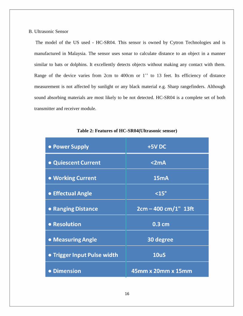
B. Ultrasonic Sensor
The model of the US used - HC-SR04. This sensor is owned by Cytron Technologies and is
manufactured in Malaysia. The sensor uses sonar to calculate distance to an object in a manner
similar to bats or dolphins. It excellently detects objects without making any contact with them.
Range of the device varies from 2cm to 400cm or 1’’ to 13 feet. Its efficiency of distance
measurement is not affected by sunlight or any black material e.g. Sharp rangefinders. Although
sound absorbing materials are most likely to be not detected. HC-SR04 is a complete set of both
transmitter and receiver module.
Table 2: Features of HC-SR04(Ultrasonic sensor)
17
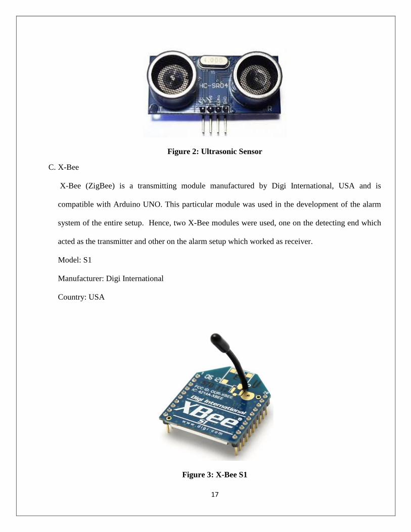
Figure 2: Ultrasonic Sensor
C. X-Bee
X-Bee (ZigBee) is a transmitting module manufactured by Digi International, USA and is
compatible with Arduino UNO. This particular module was used in the development of the alarm
system of the entire setup. Hence, two X-Bee modules were used, one on the detecting end which
acted as the transmitter and other on the alarm setup which worked as receiver.
Model: S1
Manufacturer: Digi International
Country: USA
Figure 3: X-Bee S1
18
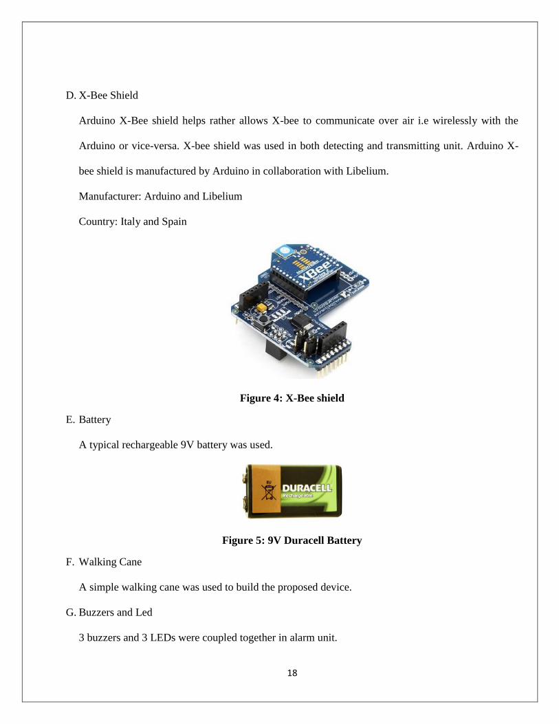
D. X-Bee Shield
Arduino X-Bee shield helps rather allows X-bee to communicate over air i.e wirelessly with the
Arduino or vice-versa. X-bee shield was used in both detecting and transmitting unit. Arduino X-
bee shield is manufactured by Arduino in collaboration with Libelium.
Manufacturer: Arduino and Libelium
Country: Italy and Spain
Figure 4: X-Bee shield
E. Battery
A typical rechargeable 9V battery was used.
Figure 5: 9V Duracell Battery
F. Walking Cane
A simple walking cane was used to build the proposed device.
G. Buzzers and Led
3 buzzers and 3 LEDs were coupled together in alarm unit.
19
H. Baby Bibs
A Baby Bib was used to develop the alarm system.
3.2. METHODS
A. Sensor Calibration
The ultrasonic sensors were calibrated by obtaining and comparing the output of the serial monitor
to the actual distance. This calibration was required for the absolute distance measurement of the
obstacle otherwise which might lead to incidents during the use of the WSC.
B. Development of the device
The proposed design of the WSC is shown as a schematic in Figure 4 and the overall functioning
of the device is also shown as a flow chart (Figure 5). Three pair of ultrasonic transreceiver
modules were arranged in a fashion to detect obstacle in front, at head level and at foot level. A
trigger signal was given to the transmitting end of the US module which after echo was received at
the echo end.
This echoed signal was then analysed to extract information regarding the obstacle present. The
received signal had the information in terms of time period which was deciphered in terms of
distance by using the formula:
D= T/58.2,
Ddistance of the obstacle;
Ttime period of the signal.
This cycle of transmitting and receiving was repeated every 100ms hence a continuous obstacle
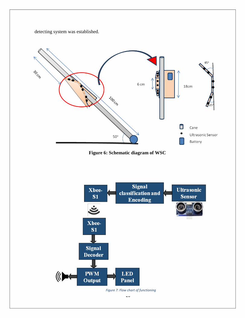
20
detecting system was established.
Figure 6: Schematic diagram of WSC
Figure 7: Flow chart of functioning
21
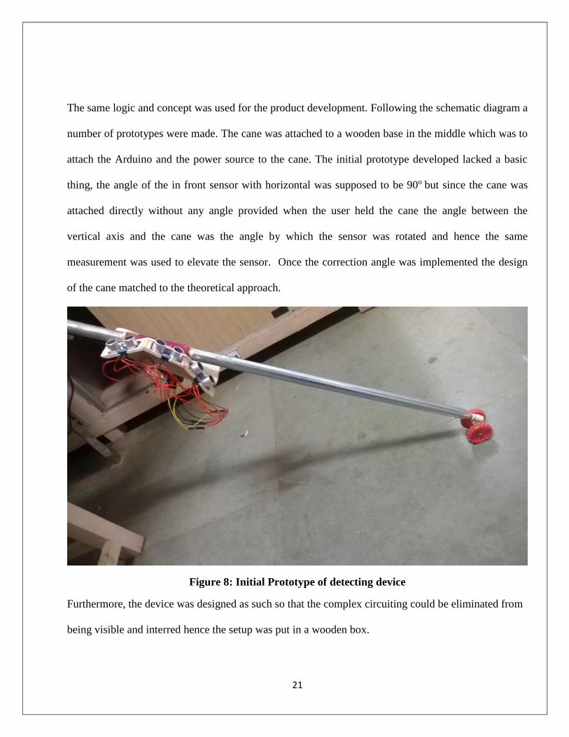
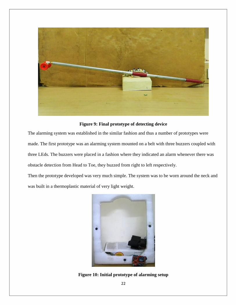
The same logic and concept was used for the product development. Following the schematic diagram a
number of prototypes were made. The cane was attached to a wooden base in the middle which was to
attach the Arduino and the power source to the cane. The initial prototype developed lacked a basic
thing, the angle of the in front sensor with horizontal was supposed to be 90o but since the cane was
attached directly without any angle provided when the user held the cane the angle between the
vertical axis and the cane was the angle by which the sensor was rotated and hence the same
measurement was used to elevate the sensor. Once the correction angle was implemented the design
of the cane matched to the theoretical approach.
Figure 8: Initial Prototype of detecting device
Furthermore, the device was designed as such so that the complex circuiting could be eliminated from
being visible and interred hence the setup was put in a wooden box.
22
Figure 9: Final prototype of detecting device
The alarming system was established in the similar fashion and thus a number of prototypes were
made. The first prototype was an alarming system mounted on a belt with three buzzers coupled with
three LEds. The buzzers were placed in a fashion where they indicated an alarm whenever there was
obstacle detection from Head to Toe, they buzzed from right to left respectively.
Then the prototype developed was very much simple. The system was to be worn around the neck and
was built in a thermoplastic material of very light weight.
Figure 10: Initial prototype of alarming setup
23
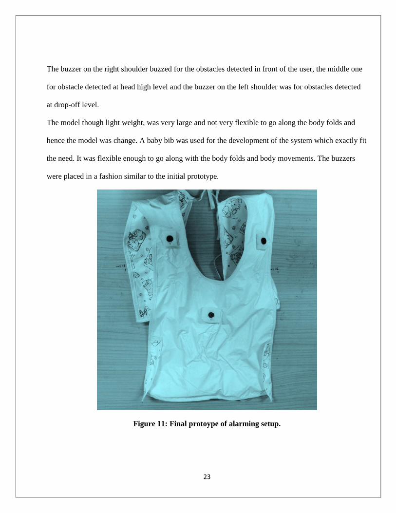
The buzzer on the right shoulder buzzed for the obstacles detected in front of the user, the middle one
for obstacle detected at head high level and the buzzer on the left shoulder was for obstacles detected
at drop-off level.
The model though light weight, was very large and not very flexible to go along the body folds and
hence the model was change. A baby bib was used for the development of the system which exactly fit
the need. It was flexible enough to go along with the body folds and body movements. The buzzers
were placed in a fashion similar to the initial prototype.
Figure 11: Final protoype of alarming setup.

24
CHAPTER 4
RESULTS
AND
DISCUSSIONS
25
4. RESULTS AND DISCUSSIONS
The conventional navigation aids were lacking to produce the amount of information required for safe
and speedy mobility of blind people. On the other hand the ETAs proved to be of very much
importance as the amount o information they were capable of collecting from the surrounding was
much more than any conventional navigation aid. ETAs are device which are designed to be light
weight so that it does not put an extra effort on the user. Moreover, these devices need to be of such a
shape and size that describes them to be portable.[28]. The portability also means that the device
should be a standalone device which requires it to be available with a portable power source as well.
The power source, hence needs to be of optimum capacity so that the device can run for a long
duration before it gets drained which implies that it is must for the device to be less power consuming
[29]. Going for the above mentioned important points which can’t be overlooked, it is necessary for
the device to be cost effective so that even the weaker section of the society can avail it easily [30].
With reference to the above concern a portable cane was designed based on the distance measurement
principle of ultrasonic sensors. The range of the device was set to 5-150 cm for the upper and middle
sensors which were responsible for detection at head level and waist level respectively. However, for
detection of holes and sudden bumps the same logic was applicable but with a not logic added. The
lower sensor was found to have an ability to easily detect bumps of a height greater than 10cm e.g.
steps, and pits as well.
The alarm system was designed keeping in mind to lower the complex wired system and for the same
purpose wireless transmission of the control signals was adapted.
26
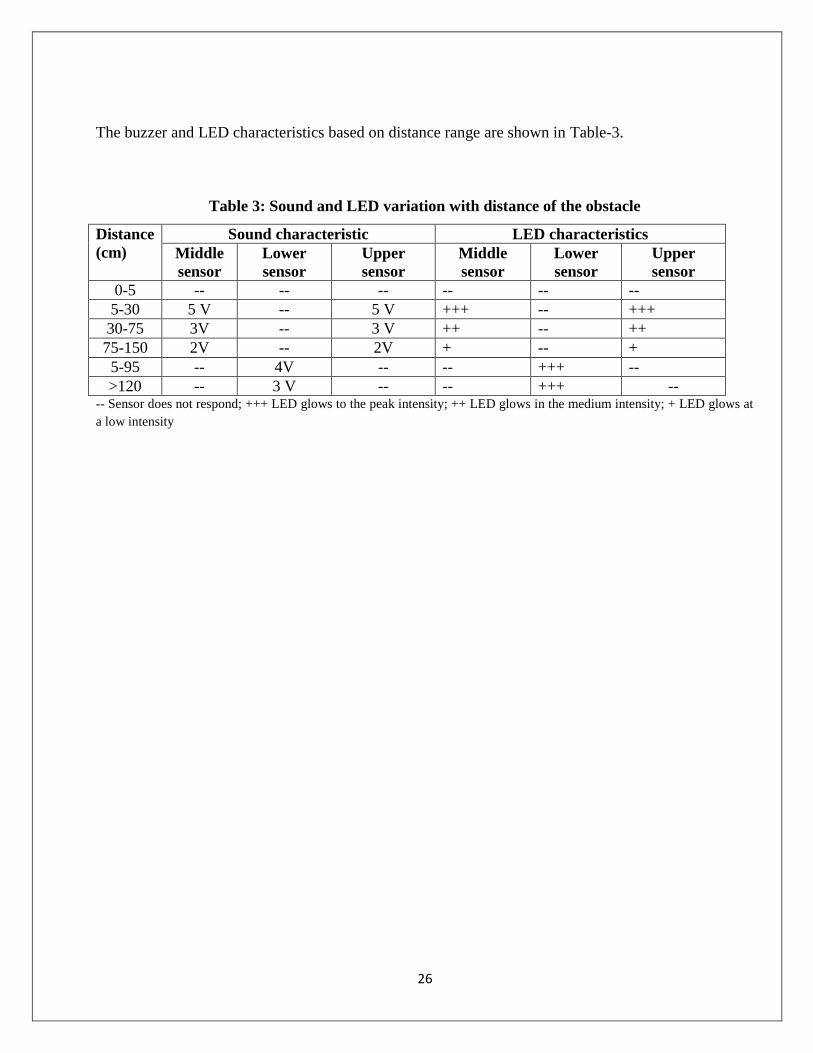
The buzzer and LED characteristics based on distance range are shown in Table-3.
Table 3: Sound and LED variation with distance of the obstacle
Distance
(cm)
Sound characteristic LED characteristics
Middle
sensor
Lower
sensor
Upper
sensor
Middle
sensor
Lower
sensor
Upper
sensor
0-5 -- -- -- -- -- --
5-30 5 V -- 5 V +++ -- +++
30-75 3V -- 3 V ++ -- ++
75-150 2V -- 2V + -- +
5-95 -- 4V -- -- +++ --
>120 -- 3 V -- -- +++ -- -- Sensor does not respond; +++ LED glows to the peak intensity; ++ LED glows in the medium intensity; + LED glows at
a low intensity

27
CHAPTER 5
CONCLUSION
28
5. CONCLUSION
The study of the device used 3 pairs of US module used for the distance measurement function
of the device. The device design supposed to detect the both aerial and ground obstacle was
efficient. The range set for the efficient distance measurement by the device was set purposefully
to 5-150 cm. In this range the device detected the obstacles and generated corresponding visual
and audio signals to alarm the user. The visual signal though was just to ensure the audio signals
were working as required. The results obtained by trial from a group of volunteers who walked
an obstructed path blindfolded were promising and furthermore trials will be conducted. The
results were promising to an extent that ensures the safety and speed of the mobility of the
deprived user. The WSC is supposed to be integrated with a GPS system to ease the navigation
in unfamiliar pathways via a central monitoring system. The WSC being cost effective is thus
expected to be used by majority of the visually deprived section of the society.
29
CHAPTER 6
REFERENCES
30
REFERENCES 1. Bousbia-Salah, M., M. Bettayeb, and A. Larbi, A navigation aid for blind people. Journal
of Intelligent & Robotic Systems, 2011. 64(3-4): p. 387-400.
2. Pradeep, V., G. Medioni, and J. Weiland. Robot vision for the visually impaired. in
Computer Vision and Pattern Recognition Workshops (CVPRW), 2010 IEEE Computer
Society Conference on. 2010. IEEE.
3. Faria, J., et al. Electronic white cane for blind people navigation assistance. in World
Automation Congress (WAC), 2010. 2010. IEEE.
4. Nunokawa, K., S. Ino, and K. Doi, Vibration of the White Cane Causing a Hardness
Sense of an Object, in HCI International 2013-Posters’ Extended Abstracts. 2013,
Springer. p. 493-497.
5. Hersh, M., Deafblind people, stigma and the use of communication and mobility assistive
devices. Technology and Disability, 2013. 25(4): p. 245-261.
6. Morrison, R., et al. Design of a Novel Electronic Travel Aid to Assist Visually Impaired
Individuals Navigate Their Environment. in ASME 2012 Summer Bioengineering
Conference. 2012. American Society of Mechanical Engineers.
7. Kim, S.Y., et al., Electronic Cane for Visually Impaired Persons: Empirical Examination
of Its Usability and Effectiveness, in Human Centric Technology and Service in Smart
Space. 2012, Springer. p. 71-76.
8. Doi, K., et al. Influence of the Weight of White Canes on Muscle Load of the Upper
Limbs. in World Congress on Medical Physics and Biomedical Engineering May 26-31,
2012, Beijing, China. 2013. Springer.
9. Nalavade, K., et al., Use of ultrasonic sensors, GPS and GSM technology to implement
alert and tracking system for Blind Man. 2014.
10. Martins, M.M., et al., Assistive mobility devices focusing on Smart Walkers:
Classification and review. Robotics and Autonomous Systems, 2012. 60(4): p. 548-562.
11. Takizawa, H., et al. Kinect cane: An assistive system for the visually impaired based on
three-dimensional object recognition. in System Integration (SII), 2012 IEEE/SICE
International Symposium on. 2012. IEEE.
12. Ye, C. Navigating a Portable Robotic Device by a 3D imaging sensor. in Sensors, 2010
IEEE. 2010. IEEE.
31
13. Bouhamed, S.A., et al. New electronic cane for visually impaired people for obstacle
detection and recognition. in Vehicular Electronics and Safety (ICVES), 2012 IEEE
International Conference on. 2012. IEEE.
14. Jubril, A., et al., Obstacle detection system for visually impaired persons: Initial design
and usability testing. Technology and Disability, 2013. 25(3): p. 199-205.
15. Brabyn, J.A., New developments in mobility and orientation aids for the blind.
Biomedical Engineering, IEEE Transactions on, 1982(4): p. 285-289.
16. Hossain, E., et al., State of the art review on walking support system for visually impaired
people. International Journal of Biomechatronics and Biomedical Robotics, 2011. 1(4): p.
232-251.
17. Ifukube, T., T. Sasaki, and C. Peng, A blind mobility aid modeled after echolocation of
bats. Biomedical Engineering, IEEE Transactions on, 1991. 38(5): p. 461-465.
18. Dunai, L., et al., Sensory Navigation Device for Blind People. Journal of Navigation,
2013. 66(03): p. 349-362.
19. Dunai, L., et al. Real-time assistance prototype—A new navigation aid for blind people.
in IECON 2010-36th Annual Conference on IEEE Industrial Electronics Society. 2010.
IEEE.
20. Wang, Y. and K.J. Kuchenbecker. HALO: Haptic Alerts for Low-hanging Obstacles in
white cane navigation. in Haptics Symposium (HAPTICS), 2012 IEEE. 2012. IEEE.
21. Kumar, A., et al., An embedded system for aiding navigation of visually impaired
persons. Current Science (00113891), 2013. 104(3).
22. Bujacz, M., et al., Sonification of 3d scenes in an electronic travel aid for the blind.
Advances in Sound Localization, 2011: p. 251-268.
23. Sanz, P.R., et al., Scenes and images into sounds: a taxonomy of image sonification
methods for mobility applications. Journal of the Audio Engineering Society, 2014.
62(3): p. 161-171.
24. Badoni, M. and S. Semwal, Discrete Distance and Water Pit Indicator using AVR
ATmega8 in Electronic Travel Aid for Blind. International Journal of Disaster Recovery
& Business Continuity, 2011. 2.
25. Adebiyi, A., et al. Evaluation of feedback mechanisms for wearable visual aids. in
Multimedia and Expo Workshops (ICMEW), 2013 IEEE International Conference on.
2013. IEEE.
32
26. Mustapha, B., A. Zayegh, and R. Begg. Multiple sensors based obstacle detection system.
in Intelligent and Advanced Systems (ICIAS), 2012 4th International Conference on.
2012. IEEE.
27. Ercoli, I., P. Marchionni, and L. Scalise. A wearable multipoint ultrasonic travel aids for
visually impaired. in Journal of Physics: Conference Series. 2013. IOP Publishing.
28. Ito, K., et al. Development of the Future Body-Finger: A Novel Travel aid for the Blind.
in AMBIENT 2012, The Second International Conference on Ambient Computing,
Applications, Services and Technologies. 2012.
29. Gassert, R., et al., White cane with integrated electronic travel aid using 3D TOF sensor.
2013, Google Patents.
30. Kumar, A., et al. An electronic travel aid for navigation of visually impaired persons. in
Communication Systems and Networks (COMSNETS), 2011 Third International
Conference on. 2011. IEEE.