development of new raft technologies for · pdf filecentre for shellfish research at vancouver...
TRANSCRIPT
DEVELOPMENT OF
NEW RAFT TECHNOLOGIES
FOR THE
BC SHELLFISH AQUACULTURE INDUSTRY

Centre for Shellfish Research at Vancouver Island University
DEVELOPMENT OF NEW RAFT TECHNOLOGIES
FOR THE BC SHELLFISH AQUACULTURE INDUSTRY
Project Report
Date and Revision October 13, 2010 Rev 3.0 Submitted to: Fisheries and Ocean Canada Attn: Sean Irvine Vancouver, BC BC Shellfish Growers Association Attn: Tom Broadley, President
Courtenay BC
Authors: Brian Kingzett and Joy Wade
Vancouver Island University Centre for Shellfish Research 900 Fifth Street, Nanaimo BC V9R 5S5
With Ryan Nicoll and Dean Steinke
Dynamic Systems Analysis Ltd. PO Box 3075, STN CSC 3800 Finnerty Road, Hut R Victoria, BC, V8W 3W2
Project Contact : Brian Kingzett, M.Sc., Deep Bay Field Station Manager
Centre for Shellfish Research at Vancouver Island University 900 Fifth Street, Nanaimo, B.C. Canada V9R 5S5 Tel: (250) 740-6399 / Fax: (250) 740-6353 Email: [email protected] / www.viu.ca/csr/
Acknowledgements: This project was made possible by the Aquaculture Innovation and Market Access
Program of Fisheries and Oceans Canada and we are extremely grateful for the support. The Innovation and Development Corporation at UVIC facilitated and support early portions of the work. This project was conducted with the BC Shellfish Growers Association in conjunction with ex R&D Manager Dave McCallum. We received significant input from individual BC Shellfish Growers as well as manufacturers and product suppliers, all of whom made this project a success.

Development of advanced raft technologies - October 13, 2010
Page i
Executive Summary
The necessity of creating better culture raft designs to effectively modernize the shellfish farming industry has been a significant priority to the BC shellfish culture industry. Recently, it has become apparent that the vast majority of industry infrastructure is in need of redesign, upgrades and new investment. The goal of this project was to respond to industry need and to develop a new shellfish aquaculture raft design using current state-of-the-art materials and techniques. The resulting “open” design will hopefully create high quality rafts for the BC Shellfish Farming industry and improve industry economic profitability and environmental sustainability. Having long-life raft designs that will withstand significant loads from high wind and wave action will reduce industry’s contribution of debris on beaches and subsequently save farmers time and money to replace lost and broken equipment. The Centre for Shellfish Research conducted an open-source development process with industry, component manufacturers and experts. Two workshops were held, one at the beginning of the project to engage the industry and allow the opportunity for the exchange of ideas and needs to be incorporated into the design. The second industry workshop was held after preliminary designs were complete allowing the opportunity for feedback before final design decisions were made. In addition numerous conversations were conducted with industry members in BC and the US throughout the project. Expert engineers (Dynamic Systems Analysis) were engaged to work with the project team to assist in developing prototype designs and to provide design recommendations to independent industry efforts. Virtual dynamic systems modelling was employed to simulate how various materials and structures would perform in a dynamic marine environment and greatly accelerated the range of materials and concepts that could be analyzed prior to physical prototyping. Existing industry standard trimaran and catamaran rafts were modelled to determine weaknesses and safety factors and used as a guideline in new designs. A wide variety of materials were simulated to determine which would be most suitable as potential component materials in terms of both minimum strengths and cost effectiveness. After testing more than 30 designs virtually, four final designs based on two styles (A & B) were developed for physical prototyping. Final designs use a combination of primary structural beams (steel) and secondary interstitial beams. The supporting structure of the rafts is a combination of galvanized steel 4” steel 'T' and 'I' beams, assembled with galvanized bolts in order that rafts can be bolted together onsite with simple tools. Standard steel stock comes in 40’ lengths and to maximize the use of steel, the raft dimensions were extended to 27.6’ x 27.6’ (2/3d’s) of a standard beam. Rotomolded dock floats (billets) manufactured by ACE Plastics were selected. A summary comparison is shown in the following table.

Centre for Shellfish Research at Vancouver Island University
Page ii
Page ii
Comparison of styles.
Raft “A” – 6 Beam raft CAD image Raft “B” – 5 Beam raft CAD image Overall, we believe we have been successful in achieving the project objectives. The prototype designs meet the project goals and criteria establish during industry discussions . Both raft styles are approximately 1m x 1m larger than existing designs (8m x 8m), with more capacity (>80 tray droppers and >12,000 lbs floatation). In summary these designs:
May be able to be moored in a similar fashion to existing designs
Are as simple as possible with few “custom parts” and structures that could be assembled by farmers with a minimum of tools on-site.
Have integral structure constructed from non biodegradable materials virtually tested to be capable of withstanding normal to significant weather conditions.
Isolate the structure of the raft from the components that physically suspend the culture stock so that failure of components suspending stock does not contribute to overall raft failure.
Have durable components that do not degrade and/or can be maintained or repaired in situ.
Have commercially available plastic foam filled billets as floatation that will not degrade in the marine environment if damaged.
Prototypes are now being tested and demonstrated at the Deep Bay Field Station in Baynes Sound, BC. Shop drawings of prototypes are available to industry for construction, further testing and continuing advancement.
Main cross
beam component
Raft
dimension
(feet)
Main beam
dimension
(in x in x
ft)
# Main
cross
beams
#
Floats
Min #
Drop
lines
Max #
Drop
lines
% Sub-
mergence
(Max)
% Sub-
mergence
(Min)
A -galvanized I beam unequal spacing 27x27 4x4x27 6 6 77 121 87 64
B -galvanized I beam equal spacing 27x27 4x4x27 5 6 96 144 97 72

Development of advanced raft technologies - October 13, 2010
Page iii
Table of Contents
1.0 Introduction ............................................................................................. 1
1.1 Projective objectives: ......................................................................... 1
1.2 Background: ..................................................................................... 2
1.3 Prior work ........................................................................................ 3
1.4 Partners ........................................................................................... 4
1.5 Potential Benefits to Industry and Commercialization ............................. 5
2.0 Methodology and objectives ..................................................................... 6
2.1 Industry involvement ......................................................................... 6
2.2 Engagement of experts ...................................................................... 6
2.3 Modeling a series of prototypes using computer simulations ................... 6
2.4 Simulation process .......................................................................... 10
2.5 Project communications ................................................................... 12
2.6 Development of prototypes ............................................................... 12
3.0 Outcomes and results ............................................................................. 13
3.1 Consultation outcomes ..................................................................... 13
3.2 Local and international design review ................................................ 14
3.3 Summary of design requirements ...................................................... 16
3.4 Simulation results ........................................................................... 17
3.5 Final design and prototype development ............................................ 19
3.6 Comparison of prototype styles ......................................................... 22
3.7 Projected Raft Costs ........................................................................ 22
4.0 Discussion .............................................................................................. 25
4.1 What we like about the prototype designs .......................................... 25
4.2 What we don’t like about the prototype design .................................... 26
4.3 Future work .................................................................................... 27
List of Appendices
Appendix 1 – Summary material analysis:
Appendix 2: Materials tested for frame component suitability for a 27’x27’ raft
Appendix 3: Fabrication pictures
Appendix 4: Raft Plan documents


Development of advanced raft technologies - October 13, 2010
Page 1
1.0 Introduction
1.1 Projective objectives:
The necessity of creating a better raft to effectively modernize the shellfish farming industry has been a significant priority to the BC shellfish culture industry. Recently, it has become very apparent that the vast majority of industry infrastructure is in need of redesign, upgrades and new investment. Having new raft designs that will withstand significant loads from high wind and wave action will reduce industry’s contribution of debris on beaches and subsequently save farmers time and money to replace lost and broken equipment. As a result the BC Shellfish Growers Association (BCSGA) has included testing new raft designs on their working list of industry research and development priorities1. The goal of this project was to respond to the industry need and develop new shellfish aquaculture raft designs using current state-of-the-art materials and techniques. The resulting open source designs can be used to create high quality rafts for the BC shellfish farming industry which will in turn improve industry economic profitability and environmental sustainability. This occurred by bringing much needed engineering support to this issue and engaging industry in a multi-disciplinary collaborative design process. Funding from the Aquaculture Innovation and Market Access Program (AIMAP)2 has allowed us to design, test and build alternative rafts to the current designs being used by industry. The specific objectives of this project included:
1. Conduct and facilitate an open-source development process with industry, component manufacturers and experts.
2. Engage expert engineers to work with industry to develop prototype designs and to provide design recommendations to independent industry efforts.
3. Maintain a project communications strategy through information on BCSGA and CSR websites, trade journal articles, industry presentations and press releases.
4. Model a series of prototypes using computer simulations.
5. Model and test in-situ various prototypes at the Deep Bay Field Station under commercial culture situations while making rafts available for demonstration purposes.
6. To develop and test up to four prototype designs for “next generation” shellfish rafts
7. Provide a report for dissemination to industry outlining manufacture detailing, design and capital costs
1 http://bcsga.ca/wp-content/uploads/2008/04/bcsga_researchprojectpriorities_working_2008.pdf
2 http://www.dfo-mpo.gc.ca/aquaculture/sustainable-durable/index-eng.htm

Centre for Shellfish Research at Vancouver Island University
Page 2
1.2 Background:
The current state of the art in deepwater shellfish aquaculture is to use 8 metre2 rafts constructed of lumber and either unprotected or coated /covered Styrofoam for the cultivation of shellfish such as oysters and mussels. Generally, these rafts have been built using the expertise and the materials readily available to the farmers. In the last four years with particularly severe wind storms, it has become apparent that more durable rafts are needed as many rafts have broken up and been destroyed resulting in loss of product equipment and environmental/community concerns about debris.
Figure 1. CSR Computer model of existing trimaran
design and production raft destroyed by storm (December 2006)
The CSR has estimated that losses from a single storm damaged raft can include the following:
tray oysters = $12,000 – $18,000 trays = $8,000 raft = $2000 Total approx. $25,000
it has become apparent that more
durable rafts are needed as many rafts
have broken up and been destroyed
resulting in loss of product equipment
and environmental/community concerns
about debris.

Development of advanced raft technologies - October 13, 2010
Page 3
Key facts about the current designs
Catamaran and Trimaran designs
Framework and decking- wood; wood and steel
Dimensions- 24’ x24’, using 2”x6” and 2”x8” lumber to accommodate a two foot square shellfish tray hung at two different depths
Floats- Styrofoam blocks wrapped in tarpaulin, some use of rotomolded plastic. Flotation costs range from $400 for plain Styrofoam, to $1800 for rotomolded foam
Useable life of approximately 5 years.
Approx 80-88 tray stack droppers per raft.
Design approach: “if it breaks build it bigger”.
Estimated >1000 over “shelf life” in BC.
Cost- Large trimaran design costs $6500 + manpower. Smaller trimaran rafts (24’x 24’) cost $1400 - $2000 + construction costs.
During a single storm in December 2006, it was estimated that as many as 100 rafts were severely damaged or lost. In years following, anecdotal reports are that losses continue. This estimate does not take into account the costs of salvage, removal and disposal of ruined equipment or the social and environmental costs of marine debris lost to the marine environment. This has resulted in significant media attention and social issues related to marine debris washing up on local beaches. Globally shellfish farmers are developing new designs specific to their area and culture methods based on better and more durable materials. This advanced development has so far excluded much of the BC industry. Since winter storms devastated a large number of farms in December 2006, the CSR and the BCSGA have made the development of new more durable technologies a specific research priority and have engaged industry and experts in a collaborative design process that has suffered for lack of resources to develop and test prototypes and then introduce these to the industry at large.
1.3 Prior work
The CSR has worked opportunistically on responding to industry requirements for new raft designs since spring of 2007 when the CSR hosted a one day industry workshop to discuss the issue, bring experts together with industry and engage in a discussion to move the industry forward. This highly successful workshop was funded by the BC Ministry of Agriculture and Lands. Subsequent to the workshop, the CSR with the UVIC Innovation and Development Corporation (IDC) hosted a working luncheon
Globally shellfish farmers are developing
new designs specific to their area and
culture methods based on better and
more durable materials.

Centre for Shellfish Research at Vancouver Island University
Page 4
to discuss the issue. This first workshop included CSR staff, representative of 6 shellfish companies, an engineer from Camosun College, representatives from two commercial float companies and a business specialist from UVIC Innovation and Development Corporation (IDC). Participants in this workshop shared and identified a number of key criteria for moving forward including.
Issues and common points of failure with current raft designs
Design considerations for a new raft design?
What the necessary attributes of a good raft are in terms of operational characteristics, size, flotation, stability, modularity, and service lifetime etc.?
How much they would be willing to spend for a raft, and what cost benefits would be necessary to justify new raft designs?
Figure 2. Raft design workshop at Centre for Shellfish
Research
1.4 Partners
This project was conducted with the BC Shellfish Growers Association (BCSGA). The shellfish industry has been engaged in preliminary discussions prior to this project and a model for industry involvement was established. Co-leadership on this project with the BCSGA ensured that industries concerns were heard and met during the process.
Tom Hopper, Seaco Marine makes a point
at working lunch, raft workshop of
industry, manufacturers, BCSGA and
engineers facilitated by CSR and
sponsored by UVIC IDC.
January 2008.

Development of advanced raft technologies - October 13, 2010
Page 5
1.5 Potential Benefits to Industry and
Commercialization
Commercialization potential
Industry estimates collaborated with site development information provided by BC Ministry of Agriculture and Lands have indicated that there are in excess of 1000 rafts in British Columbia, the majority of which are estimated to be more than five years old or past the half-way mark of normal lifespan. Assuming that 100 rafts at a very minimum are replaced per year with next generation rafts this would removed approximately 22,000 cubic feet of Styrofoam per year from risk of loss to the marine environment per year. Construction of another 100 new rafts per year for industry growth would prevent an equivalent amount of Styrofoam from being placed into the marine environment. Better designs will allow the industry to reduce risk of product and equipment loss due to storm damage during climax changed which may result in more severe weather events on the British Columbia coast. New more environmentally sustainable and aesthetically less intrusive designs will also contribute to the shellfish industry achieving more “social license” from coastal communities and thus adding to overall development potential. Production from an anticipated 1000 new rafts introduced over the next five years would produce wholesale product values of between 12- 18 million dollars annually Secondary component fabricator/manufacturers and raft assembly firms will benefit by production of the necessary parts, integrating existing manufacturer’s floats and sell the shellfish rafts as part of their product line, either selling the entire raft or selling the individual components. Over the next five years it is anticipated that over 1000 rafts could enter service with a materials (secondary supplier) opportunity of 4 – 5 million dollars based on what industry has stated total capital costs for new rafts should be. Open licensing is expected to promote commercialization. Prototype designs produced through this project are being made publicly available to the BC shellfish industry through the Centre for Shellfish Research and the BCSGA.
New more environmentally
sustainable and aesthetically less
intrusive designs will also contribute
to the shellfish industry achieving
more “social license” from coastal
communities and thus adding to
overall development potential
Prototype designs produced
through this project are being
made publicly available to the
BC Shellfish industry through
the Centre for Shellfish
Research and BCSGA.

Centre for Shellfish Research at Vancouver Island University
Page 6
2.0 Methodology and objectives
2.1 Industry involvement
A goal of the project was to conduct and facilitate an open-source development process with industry, component manufacturers and experts. Two workshops were held, one at the beginning of the project to engage the industry and allow the opportunity for the exchange of ideas and needs to be incorporated into the design. The second industry workshop was held after preliminary designs were complete allowing the opportunity for feedback before final design decisions were made. In addition, numerous conversations were conducted with industry members in BC and the US throughout the project.
2.2 Engagement of experts
Expert engineers were engaged to work with the project team to assist in developing prototype designs and to provide design recommendations to independent industry efforts. Vancouver Island University conducted an open Request for Qualifications among engineering firms and retained Dynamic Systems Analysis of Victoria. Dynamic Systems Analysis, Ltd. (DSA) specializes in risk management in marine environments. DSA primarily focuses on the following industries: renewable energy, submersibles & subsea robotics and ocean engineering: moorings & riser design. DSA is located on the University of Victoria campuS in a partnership with the UVIC technology transfer office and the Innovation and Development Corporation. The core technology used by DSA is an advanced engineering analysis tool called ProteusDS®. This proprietary software was developed by DSA and is used to rapidly construct accurate virtual prototypes of marine assets or operations. The response of the constructed system to ocean wind, waves, and current conditions allows DSA to intelligently assess system performance and prevent catastrophic structural failure.
2.3 Modeling a series of prototypes using computer
simulations
Concept of simulation based design
In terms of mechanical engineering, dynamics analysis is the study of forces and their relationship to the motion of bodies. If the nature of loading on a body is understood and a model of the body can be created, dynamic analysis will predict the motion of the body through time. An accurate understanding of the dynamics of a mechanical system is critical to ensure reliable and efficient design.
ProteusDS® software was
developed by DSA and is used to
rapidly construct accurate virtual
prototypes of marine assets or
operations.

Development of advanced raft technologies - October 13, 2010
Page 7
Computer simulations were utilized by Dynamic Systems Analysis (DSA) to virtually test a wide variety of prototypes developed by the project team. The conceptual theory behind this approach is that to analyze the dynamics of a system, the relationships between the system components must be defined. Traditional analytical techniques and linearized analysis can become too onerous, time consuming, and even impossible. However, the use of nonlinear numerical simulations allows the motions complex mechanical systems of any size to be predicted in a reliable and economical fashion. Examples of the elastic forces calculated and modelling during dynamic analyses are shown in the following diagram.
Figure 3. Factors utilized in dynamic cable modeling showing forces acting on a cable and a raft beam.
Simulation plan
The goal of conducting dynamic analyses on virtual prototypes is to remove design weaknesses (optimize) without having to physically construct prototypes. The internal stresses of the raft beams are a function of the dynamic internal forces of the elastic joints in the model. Once the internal stresses exceed the yield strength of the material (incorporating an appropriate safety factor), failure of the object, in this case a culture raft is anticipated. A standard virtual model of shellfish mooring for raft simulations was developed with mooring properties and

Centre for Shellfish Research at Vancouver Island University
Page 8
schematics based on industry norms. In order to establish internal forces of the raft during environmental forcing, a series of virtual raft models were developed with a series of rigid beam segments with elastic joints. In order to facilitate parametric studies on different materials, geometries, and raft configurations computer scripts were generated in order to quantify the stiffness and inertias of the raft components given fundamental material properties such as density, stiffness, and characteristic dimensions. Once failure conditions of the raft have been anticipated, materials and raft geometry can be varied to address the design issues. The parametric study was constrained by the allowable materials and geometry dictated by industry feedback, which was determined by the project team staff and took into account numerous “workability” decisions. Raft materials of PVC, wood, steel, and other materials were be incorporated in the simulation model as allowed by constraints. In summary, this procedure allowed the design team to model elastic virtual rafts, anticipate failures and try many beam shapes & materials. The specific design process included:
1) Setting the environment (depth, sea state)
2) Establishing safety factors based on the standard industry trimaran raft
3) Simulating to benchmark beam shapes + materials
4) Repeating 3)!...... The: simulation-based design tested the following:
Shapes: I-beam, pipe/tube, rectangular beams
Structural materials: aluminum, steel, fiberglass, HDPE, plastic wood, wood
Rafts styles: trimaran, catamaran, 'frame' catamaran The following definitions are important in understanding the results of the simulations.
Yield stress- the internal pressure level a structure can sustain at the verge of failure. Yield stress is a known value for many different materials. Steel for example has a significantly higher yield stress over wood.
Safety factor- the ratio of the yield stress over the applied
stress of a structure. A safety factor of 1 or lower implies the structure has failed. A design with a larger safety factor will be more tolerant to uncertainties in loading and material imperfections. Safety factors are affected by the material as well as the situation in which it is used. For our usage, a safety factor of 10 is desirable based on the American Bureau of Shipping’s
Development of advanced raft technologies - October 13, 2010
Page 9
Guide for Building and Classing Floating Production Installations for critical non-field repairable members on offshore structures.
Wing beam- the amount of overhang (unsupported beam length) on the outside of the floats in current designs.
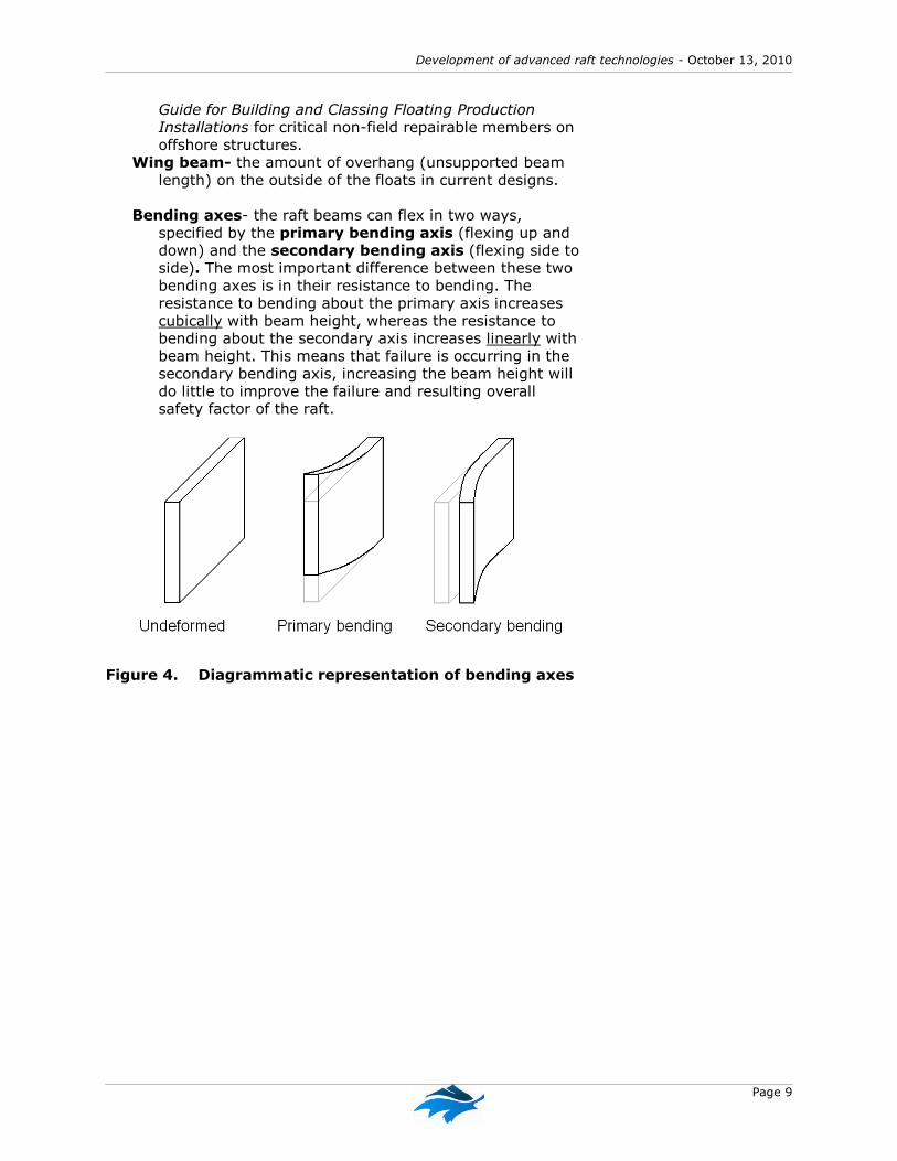
Bending axes- the raft beams can flex in two ways,
specified by the primary bending axis (flexing up and down) and the secondary bending axis (flexing side to side). The most important difference between these two bending axes is in their resistance to bending. The resistance to bending about the primary axis increases cubically with beam height, whereas the resistance to bending about the secondary axis increases linearly with beam height. This means that failure is occurring in the secondary bending axis, increasing the beam height will do little to improve the failure and resulting overall safety factor of the raft.
Figure 4. Diagrammatic representation of bending axes

Centre for Shellfish Research at Vancouver Island University
Page 10
Figure 5. Representational engineering model of
shellfish raft under dynamic analysis
2.4 Simulation process
Step 1: Determine environmental conditions
Weather data from 2 stations in the Strait of Georgia (Stations 46131 and 46146) was used to generalize worst case scenario wind and wave action in the area. From this data it was determined that a 3m, 8 second period wave would be used in initial simulations.
Each sphere in the graphical
representation is a visual representation
of the mass and drag through seawater
of a tray of shellfish in culture. Note that
the upper level of trays is subjected to
more lateral stress in waves than the
lower layer that is suspended on longer
dropper lines.

Development of advanced raft technologies - October 13, 2010
Page 11
Figure 6. Rendered still image from dynamic
simulation modeling visualization
Step 2: Model industry standard rafts
Existing industry standard trimaran and new catamaran raft designs were modeled to determine weaknesses and safety factors to use as a guideline in new designs. In order to establish a design starting point both Catamaran (2 rows of floats) and Trimaran (3 rows of floats) versions of rafts used in the shellfish industry were simulated by DSA. For each variant, a series of materials were examined with simulated wave propagations hitting the side of the rafts (beam waves) and at an angle of 45 degrees (Beam head waves). Predicted safety factors, the axis of failure and the safety factor of what we termed to be wing beams, the section that hangs out over the beam were calculated.
Step 3: Simulations of new and materials
Simulations and calculations of safety factors were conducted of new components tested with beam-head waves with 2m, 6 second period for rafts of different sizes and made of different materials. The results of these extensive simulations are summarized in Appendix 2.
Existing industry standard
trimaran and new catamaran raft
designs were modeled to
determine weaknesses and safety
factors to use as a guideline in
new designs.

Centre for Shellfish Research at Vancouver Island University
Page 12
Step 4: refinements and production of designs
Based on calculations on materials and dimensions outlined in Table 4., further refinements were made in concept. It was decided to increase the size of the raft from 24’x24’ which is determined by the maximum available size of dimension 2x6” lumber to 27’x27’. This was based on maximizing recovery from standard steel stock sizes which come in 40’ lengths by using 2/3’s of a standard 40’ length. The remaining thirds can be joined to create 27’ lengths. Having made this assumption, various materials were then simulated to determine which would be most suitable as a frame material. During this design iteration, materials were examined to determine both minimum strengths and cost effectiveness.
2.5 Project communications
This project has provided updates to industry through the BCSGA website and print newsletter Tidelines. The CSR developed a PBWiki site https://shellfishraft.pbworks.com/ during which materials and news of the project was maintained. Many producers, manufacturers and interested parties have requested access to this site. Presentations have been made about the project at conferences such as the Aquaculture Association of Canada Annual meeting in Nanaimo in May 2009, the Pacific Coast Shellfish Growers Association annual meeting in Portland, Washington in September 2009 and at the 2009 BCSGA meeting. The project received print coverage in Northern Aquaculture Magazine and the University of Victoria produced a print article on DSA and their role in the project. Additional print media arose from the announcement of funding at VIU by local Member of Parliament, Dr. James Lunney. Video simulations of raft designs were placed on YOUTUBE at:
http://www.youtube.com/watch?v=NDcAeFNSCdU An summary article of the project was included on the Deep Bay project blog at:
http://viudeepbay.com/2010/02/17/development-of-new-shellfish-raft-technologies/
This final report has been added to the Deep Bay project blog at:
http://viudeepbay.com/2010/10/13/new-raft-technology-project-final-report/
2.6 Development of prototypes
After narrowing down designs through virtual modelling, shop drawings were produced for two separate styles of prototype rafts. A Request For Proposals was issued for construction of raft components by the purchasing office of Vancouver Island University. A contract for prototypes was awarded to Advanced Integration Technologies Canada – Fabrication in Abbotsford (http://www.aint.com).
Development of advanced raft technologies - October 13, 2010
Page 13
3.0 Outcomes and results
3.1 Consultation outcomes
Design considerations raised at workshops which guided further design included the following:
Operations
Some farmers move their rafts around regularly, others do not. –rafts must be capable of being moored in semi-permanent or easy to release moorings
Linkage- Rafts are generally chained together with a spacing between the rafts of 4’-20’, larger rafts having more space between them. This is not ideal.
Modularity- Would be ideal, as it would allow growers to build a new fleet of rafts that work together over a period of years. New designs must be able to be incorporated into existing farm layouts and resemble the existing dimensions as much as possible. Note: This had a significant impact on overall design.
Ladders and walkways must be able to be mounted on the raft for safety. Most pre-existing industry rafts have wood walkways integral on the structure of rafts, but crews must still work across exposed 2x6 beams which present issues for worker safety. Overboard ladders are typically not built into raft designs but are commercially available. This led to a discussion of whether every raft should have walkways and working platforms built into the raft or should these be separate from the raft design?
Structure
Raft structure must be constructed out of materials that will not degrade in weather –This had significant effect on design
Raft design must match the weather conditions. Existing designs when new generally meet weather requirements and this be used as a baseline for design
Loading- When overloaded a single stack of trays can weigh up to 300 lbs in air (100 lbs in water).
As a raft moves up and down during ocean swells, significant shock loading from the suspended trays occurs, effectively increasing the weight that must be sustained by the structure
Floatation- A 24’ industry standard beam raft would require 12,000 lbs of floatation to support the trays of a standard mature crop.
Floatation must be sufficient enough not to cause the break-up of the raft if floats are lost

Centre for Shellfish Research at Vancouver Island University
Page 14
Redundancy- A rafting/anchoring system that will not break up as soon as one problem occurs. Note: Existing designs share structural integrity across the entire raft and when a single beam breaks the entire structure weakens often resulting in cascading failures.
Materials- must be readily available and repairable or replaceable on site by workers
Cost
Cost- must be cost effective. Existing rafts are “inexpensive” to build but have a relatively short operational lifespan (5-7 years). Cost effectiveness must be determined as a component of life cycle.
3.2 Local and international design review
Local BC designs were reviewed from the original catamaran rafts constructed on Cortes Island by Redonda Seafarms and descendant modifications of this design. Trimaran wood and foam rafts designed by Odyssey Shellfish using wood and wrapped Styrofoam and a recent catamaran raft designed by Odyssey Shellfish Ltd. using a wood structure with steel connections and roto-molded plastic floats and a combination steel and wood raft design used by Taylor Shellfish in Okeover Inlet. A comprehensive review of other international raft designs was conducted including (Maine, Puget Sound, Scotland and Spain). This included a field trip to Puget Sound to examine and discuss the pros and cons of an aluminum raft developed by Taylor Shellfish Ltd. It was noted from the design review that most other jurisdictions where shellfish culture is more established as an industry, are trending to steel structures and moulded plastic floats (Figure 7). This generally replicates the growth of the fin fish industry which moved form wood cages to more weather resistant galvanized steel structures.

Development of advanced raft technologies - October 13, 2010
Page 15
Figure 7. Steel and wood mussel raft designs Upper left – Explora galvanized steel and wood beam mussel raft –
Loch Fyne, Scotland Upper right – Aluminium and wood mussel raft – Taylor Shellfish,
Puget Sound, Washington USA. Bottom - 40x40’ galvanized steel and wood beam mussel raft – Maine
Aquaculture Equipment, Maine USA.
Centre for Shellfish Research at Vancouver Island University
Page 16
3.3 Summary of design requirements
As a result of the industry consultations and existing design review the following design criteria were established:
Must approximate the existing footprint (24’ x 24’), capacity (>80 tray droppers and >12,000 lbs flotation).
Be able to be moored in a similar fashion to existing designs
A simple design including: as few “custom parts” as possible, structures that could be assembled by farmers with a minimum of tools on-site.
Have integral structure constructed from a non biodegradable material (i.e. not wood) and capable of withstanding normal to significant weather conditions.
Isolate the structure of the raft from the components that physically suspend the culture stock so that failure of components suspending stock does not contribute to overall raft failure.
Have durable components that do not degrade and/or can be maintained or repaired in situ.
Have commercially available plastic foam filled billets as floatation that will not degrade in the marine environment if damaged.
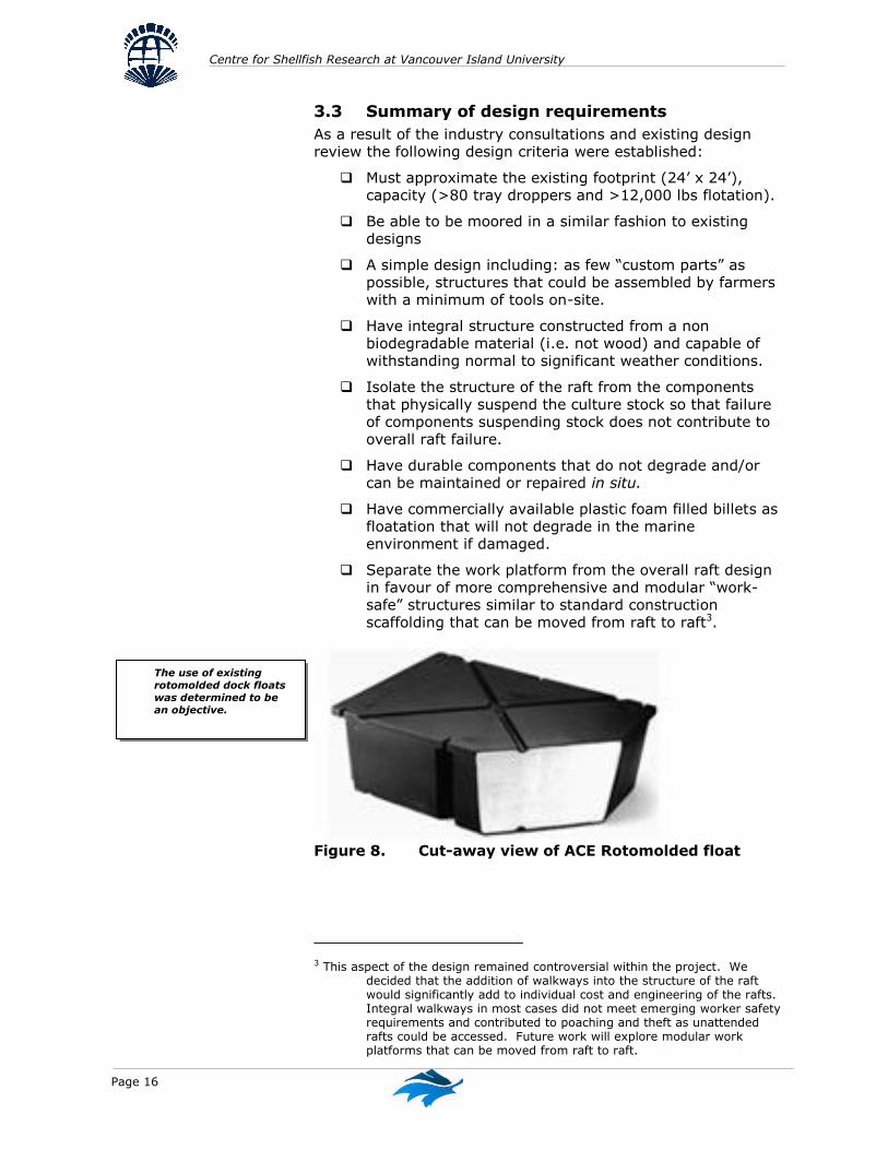
Separate the work platform from the overall raft design in favour of more comprehensive and modular “work-safe” structures similar to standard construction scaffolding that can be moved from raft to raft3.
Figure 8. Cut-away view of ACE Rotomolded float
3 This aspect of the design remained controversial within the project. We decided that the addition of walkways into the structure of the raft would significantly add to individual cost and engineering of the rafts. Integral walkways in most cases did not meet emerging worker safety requirements and contributed to poaching and theft as unattended rafts could be accessed. Future work will explore modular work platforms that can be moved from raft to raft.
The use of existing
rotomolded dock floats
was determined to be
an objective.

Development of advanced raft technologies - October 13, 2010
Page 17
3.4 Simulation results
The simulation was enhanced by first conducting engineering analyses of the existing wood raft designs being used by industry including trimaran and catamaran designs using 2”x6” wood and newer designs utilizing 2”x10” lumber. The team also tested the hypothesis of keeping existing designs but substituting wood lumber with non-degradable materials such as plastic wood. The results are summarized in the following tables.
Existing wood trimaran raft designs
Table 1. Wave propagation hitting the side of the raft
(beam waves)
Table 2. Wave propagation hitting the raft at a 45° angle (beam-head waves)
It was determined from the Trimaran raft simulations that:
Increasing wood height from 2x6 to 2x10 doubles the safety factor (3.8 to 7.9) when encountering beam waves. The failure axis continues to be the primary axis, so the design has been improved by adding beam height.
Beam-head waves (45°) cause devastating secondary bending.
Increasing the height from 2x6 to 2x10 does not significantly increase beam strength in secondary bending (2.5 to 3.8).
There is little difference in safety factors between the plastic wood and hemlock.
Material Predicted Safety Factor
Failure Axis Predicted Wing Beam Safety Factor
2x6 hemlock 3.8 1 5.7
2x6 plastic wood 4.4 1 4.4
2x10 hemlock 7.9 1 16
2x10 plastic wood 7.2 1 13.5
Material Predicted Safety Factor
Failure Axis Predicted Wing Beam Safety Factor
2x6 hemlock 2.5 2 6.2
2x10 hemlock 3.8 2 14

Centre for Shellfish Research at Vancouver Island University
Page 18
Existing wood catamaran raft
Table 3. Wave propagation hitting the side of the raft (beam waves)
It was determined from the Catamaran raft simulations that:
Because of the large unsupported masses hanging off the wing beams, the wing beam safety factor is very similar to the internal safety factor for either material (plastic wood or hemlock)
Findings
Plastic wood and hemlock have very similar safety factors in the simulations
Plastic wood is less stiff (more pliable) than wood and simulations show significantly larger beam curvatures. Using fibreglass reinforced plastic wood is not expected to improve safety factors because any imperfections in the bonding will compromise the strength of the beams and will likely fail from fatigue (cyclical) loading
To increase the safety factor of a trimaran raft under beam-head waves (45°), it would be necessary to increase the width, as an increase in height does not significantly affect the failure on the secondary axis where the damage is predicted to occur under simulation.
Under the same beam sizes, the catamaran raft safety factor was significantly less than that of the trimaran. This difference is due to the larger unsupported span of the catamaran raft.
Computer simulations of the existing wood trimaran and catamaran rafts provided details on structural weaknesses and provided a reference point for relative safety factors. Because of the extreme weather conditions that were used (3m waves with 8 second period), future simulations were based on 2m, 6 second period waves, still extreme waves for the majority of the industry’s locations, but a more likely scenario. The results of these extensive simulations are summarized in Appendix 2.
Material Predicted Safety Factor
Failure Axis Predicted Wing Beam Safety Factor
2x10 hemlock 4.2 1 4.8
2x10 plastic wood 4.2 1 4.1

Development of advanced raft technologies - October 13, 2010
Page 19
3.5 Final design and prototype development
After testing more than 30 designs virtually, four final designs based on two styles were developed for physical prototyping and shop drawings to aid construction were porduced.
Figure 9. Example shop drawing Key to the final design is that there are primary structural beams (steel) and secondary interstitial beams. The supporting structure of the rafts is a combination of galvanized steel 4” steel 'T' and 'I' beams, assembled with galvanized bolts in order that rafts can be bolted together onsite with simple tools. Relatively simple fabrication of the steel was required involving only the drilling of holes and welding of small tabs prior to galvanizing the assemblies. Standard steel stock comes in 40’ lengths and to maximize the use of steel, the raft dimensions were extended to 27.6’ x 27.6’ (2/3’s) of a standard beam. The remaining 1/3’s were then spliced together to make new full (27.6’) beams. This resulted in an expansion of the capacity of the raft while still resulting in a raft that has approximately the same size as a standard raft.

Centre for Shellfish Research at Vancouver Island University
Page 20
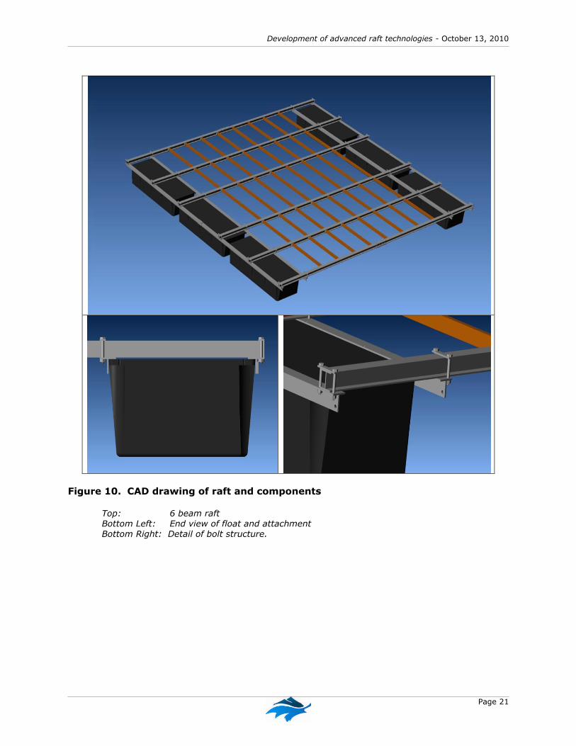
Rotomolded dock floats (billets) manufactured by ACE Roto-Mold and sold by locally Barr Plastics4 were selected. Six billets (8’x3’x2’) met the requirement for flotation. These were arranged in two groups of 3 to produce a catamaran raft. As no structural advantage was observed in producing a “wing” style raft, the billets were located at the outside of the raft primary cross beams. The “T” beams are bolted directly to the plastic billets these then are used to support the primary steel cross members which are bolted perpendicular to the T beams. Two styles of raft were designed, one using 5 primary I beams and the other 6 beams. Tabs welded on the vertical surface of the I beams support “interstitial beams” which extend between the primary beams and are nested within the I-beams. Two types of interstitial beams are being tested, standard wood lumber and plastic wood. The design intent of the interstitial beam is that the secondary beams provide a designed "weak point". In the case of extreme weather conditions leading to failure these will break losing only a portion of the crop but not the entire raft. As mentioned previously, most traditional rafts use structural beams to deploy product and when they start to fail, the entire structure loses integrity leading to catastrophic failure. This design also allows for a raft to be repaired over its lifetime, another challenge with prior raft designs.
4 http://www.barrplastics.com/foam_filled_plastic_floats.htm
Secondary (interstitial) beams
provide a designed "weak point".
In the case of extreme weather
conditions leading to failure these
will break losing only a portion of
the crop but not the entire raft.
Development of advanced raft technologies - October 13, 2010
Page 21
Figure 10. CAD drawing of raft and components
Top: 6 beam raft Bottom Left: End view of float and attachment Bottom Right: Detail of bolt structure.

Centre for Shellfish Research at Vancouver Island University
Page 22
3.6 Comparison of prototype styles
Four shellfish raft prototypes have been constructed and deployed at the Deep Bay Field Station, 2 of each version (Raft A and B). A summary comparison is shown in the following table. This analysis includes the potential number of drop lines using just interstitial beams and from the perimeter T beams as well. As well as calculated float submergence for the range of anticipated loading. Table 4. Comparison of raft prototype styles.
Computer generated images of the two raft styles showing the locations of shellfish trays below the rafts are shown in the following figures. Full shop drawings are shown in Appendix 4.
3.7 Projected Raft Costs
The component costs of the rafts will be variable on the costs of steel (variable with construction industry) and oil (which affects plastic costs) over time and the number of units purchased at in any order. We also found significant differences in the price of fabrication when bids for our request for tender were received with bids for a single raft ranging from approximately $4,000 to $10,700 per raft...Based on our results we estimate that the prototype designs will cost the following to build (not including HST). Table 5. Estimate of construction costs per raft.
Note this does not include cost of plastic wood which is estimated to add approximately $1500/raft.
Main cross
beam component
Raft
dimension
(feet)
Main beam
dimension
(in x in x ft)
# Main
cross
beams
#
Floa
ts
Min #
Drop
lines
Max #
Drop
lines
% Sub-
mergence
(Max)
%
Subme
rgence
(Min)
A -galvanized I beam unequal spacing 27x27 4x4x27 6 6 77 121 87 64
B -galvanized I beam equal spacing 27x27 4x4x27 5 6 96 144 97 72
Materials
Steel Fabrication and Galvanizing $ 4,000
Hardware $ 275
Floats 6 x 3’x8’x2’ Ace Roto-mold’ $ 2,550
Lumber – 2x6 lumber $ 540
$ 7,365
Construction
Fabrication $ 500
Materials Freight Central Vancouver Island (variable) $ 600
$ 1,100
Total per raft est. $ 8,465

Development of advanced raft technologies - October 13, 2010
Page 23
Figure 11. Raft “A” – 6 Beam raft CAD image
Figure 12. Raft “B” – 5 Beam raft CAD image

Centre for Shellfish Research at Vancouver Island University
Page 24
Figure 13. Photographs of raft construction, launching
and installation on research farm.

Development of advanced raft technologies - October 13, 2010
Page 25
4.0 Discussion
4.1 What we like about the prototype designs
Achieving goals
Overall, we believe we have been successful in achieving the project objectives. The prototype designs meet the project goals of:
Both raft styles are approximately 1mx1m larger than existing designs (8mx8m), with more capacity (>80 tray droppers and >12,000 lbs).
May be able to be moored in a similar fashion to existing designs
The design is as simple as possible with few “custom parts” and structures that could be assembled by farmers with a minimum of tools on-site.
Have integral structure constructed from a non biodegradable materials virtually tested to be capable of withstanding normal to significant weather conditions.
The designs of the isolate the structure of the raft from the components that physically suspend the culture stock so that failure of components suspending stock does not contribute to overall raft failure.
Have durable components that do not degrade and/or can be maintained or repaired in situ. We expect the lifespan of this raft to be more than 3x the current wood based designs.
Have commercially available plastic foam filled billets as floatation that will not degrade in the marine environment if damaged.
Overall Comments
The virtual design process proved to be highly effective to work through a range of options without having to build and test and allowed us to analyze existing designs and use them as benchmarks. This greatly informed the design process. Overall the design meets our intent of remaining as consistent as possible with existing sizes while increasing the size slightly to maximize the use of materials. We believe that the combination of steel structural beams and “weaker” interstitial beams provides a good compromise between required structural strength (expensive) and keeping costs to a minimum (replaceable wood interstitial beams). Any such design exercise such as this is a series of compromises. Cost as expressed by the industry consultations was repeatedly raised by the most critical factor that would prohibit industry uptake. The design process therefore resulted

Centre for Shellfish Research at Vancouver Island University
Page 26
in the design that utilized the minimum amount of materials that would still result in the required strengths and rejected more elaborate designs or more expensive materials that would have significantly increased safety factors. As discussed previously, the prototype designs differ from most existing designs in that we have chosen to separate the work platform from the overall raft design. This will require that separate work platforms are either affixed on a permanent or temporary basis to the rafts. We decided that the addition of walkways into the structure of the raft would significantly add to individual cost and engineering of the rafts and perhaps were not the best design solution. During the project we noted that this design approach was consistent with the approach taken with other advanced international designs. We also noted that worker safety issues have not received much significance in prior raft designs. Like salmon pens which now have railings and other safety features, we believe that this will be an emerging issue in the advancement of the industry. Integral walkways in most cases did not meet emerging worker safety requirements and may contribute to poaching and theft, as unattended rafts may be more easily accessed. As a result, the final design approach rejected integral walkways in favour of modular “work-safe” work platforms that can be moved from raft to raft. Future work will explore the adaptation of standard scaffolding style components used in the construction industry and their adaptation to raft work platforms that can be moved from raft to raft as required.
4.2 What we don’t like about the prototype
design
The following observations have been made to date during the testing process.
Engineering specifications indicate that 2x4 standard lumber is suitable for the secondary interstitial beams. It is our opinion that 2x6 material with the ends notched to fit within the inner portion of the I beam is more suitable.
We believe that the tabs which hold the interstitial beams may be improved by having a larger connection to the wood and that bolts may be more appropriate than screws. Alternately placing short pieces of 2x4 within the I-beam between the secondary beams can be used to “lock” the secondary beams into place.

Development of advanced raft technologies - October 13, 2010
Page 27
Plastic lumber provided the strength and the durability required. However we noted that it added substantially to the cost (>$1500/raft). As well, we noted that the 2x4 plastic lumber was prone to excessive bending in the secondary axis and do not recommend it as a result.
To date both raft styles have performed equally well in testing. Our personal preference is for the five beam version as it only uses one length of interstitial beam and has less steel. This raft does have reduced capacity.
We have noted that the addition of integral vessel tie-up cleats to the T-beams would assist when working with the rafts. We recommend adding this to future rafts as an option.
4.3 Future work
Our future work will be to continue testing of the rafts over long term and demonstrate these to industry. Feedback received from testing and from industry comments will be used to inform future iterations of these prototypes and the adoption of these designs into standard industry use. As discussed previously, developing a modular “work-safe” platform that can be easily moved from raft to raft will facilitate the use of these designs. Our future work will investigate options for platforms that are guided by standard construction industry scaffolding technologies which meet worker safety standards.


Development of advanced raft technologies - October 13, 2010
Centre for Shellfish Research at Vancouver Island University Appendix Page 1-1
Appendix 1 – Summary material analysis:
Safety values
Main cross beam component
Raft
dimension
(feet)
Main beam
dimension
# Main
cross
beams
#
Floats
Min #
Droplines
Max #
Droplines
Frame
beam
Interstitial
beam
Whole
raft
Frame beam
lateral stress
>50% total
%
Submergence
(Max)
%
Submerge
nce (Min)
standard wood trimaran 24x24 2x6x24 N/A Variable 80 80 1.7 N/A 1.7 1.0 59 59
standard wood catamaran 24x24 2x10x24 N/A Variable 80 80 4.0 N/A 4.0 1.0 56 56
galvanized I beam 20X28 4x4x20 4 8 60 108 3.1 2.0 3.1 0.0 62 41
galvanized I beam 20X28 4x4x20 5 8 60 108 3.9 2.5 3.9 0.0 64 42
galvanized I beam 20X24 4x4x20 6 6 50 90 5.4 3.1 5.4 0.0 66 45
galvanized I beam 20X29 4x4x20 7 8 60 108 5.3 2.5 5.3 0.0 67 46
galvanized I beam 24x28 4x4x24 4 8 84 132 1.7 2.0 1.7 1.0 75 54
galvanized I beam 24x28 4x4x24 5 8 84 132 2.2 2.3 2.2 1.0 77 56
galvanized I beam 24x24 4x4x24 6 6 70 110 3.2 2.5 3.2 1.0 79 58
galvanized I beam 24x29 4x4x24 7 8 84 132 2.9 2.6 2.9 1.0 81 60
galvanized I beam equal spacing (8) 27x27 4x4x27 6 6 80 120 2.4 5 2.4 1 87 66
galvanized I beam unequal spacing (8) 27x27 4x4x27 6 6 88 132 >1.7 >2.6 >1.7 1 93 70
galvanized I beam equal spacing (7) 27x27 4x4x27 6 6 70 110 >2.4 >5 >2.4 81 60
galvanized I beam unequal spacing (7) 27x27 4x4x27 6 6 77 121 >1.7 >2.6 >1.7 87 64
galvanized I beam equal spacing () 27x27 4x4x27 5 6 96 144 1.8 2.9 1.8 1 97 72
galvanized I beam unequal spacing () 27x27 4x4x27 5 6 < 1.8 <2.9 < 1.8 1

Centre for Shellfish Research at Vancouver Island University
Page 2
Main cross beam component
Raft
dimension
(feet)
Main beam
dimension
# Main
cross
beams
#
Floats
Min #
Droplines
Max #
Droplines
Frame
beam
Interstitial
beam
Whole
raft
Frame beam
lateral stress
>50% total
%
Submergence
(Max)
%
Submerge
nce (Min)
structural plastic 20X28 4x8x20 4 8 60 108 1.4 2.3 1.4 0.0 61 40
structural plastic 20X28 4x8x20 5 8 60 108 1.8 2.3 1.8 0.0 62 41
structural plastic 20X24 4x8x20 6 6 50 90 2.5 2.9 2.5 0.0 63 42
structural plastic 20X29 4x8x20 7 8 60 108 2.5 2.7 2.5 0.0 76 51
structural plastic 24x28 4x8x24 4 8 84 132 0.84 1.5 0.8 0.0 73 51
structural plastic 24x28 4x8x24 5 8 84 132 1.1 2.3 1.1 0.0 75 54
structural plastic 24x24 4x8x16 6 6 70 110 1.5 1.8 1.5 0.0 76 55
structural plastic 24x29 4x8x16 7 8 84 132 1.5 1.5 1.5 0.0 78 57
fibreglass I beam 20X28 4x4x20 5 8 60 108 2.4 2.8 2.4 0.0 58 36
fibreglass I beam 20X24 4x4x20 6 6 50 90 3.7 2.5 3.7 0.0 68 47
fibreglass I beam 20X29 4x4x20 7 8 60 108 3.6 2.4 3.6 0.0 59 37

Development of advanced raft technologies - October 13, 2010
Page 1 Appendix Page 2-1
Appendix 2: Materials tested for frame component suitability for a 27’x27’ raft
Material and form Dimension Suitability as frame
component
Aluminium
H beam 4”x4” Cost prohibitive
5”x4” Safety factor too high
6”x3.5” Safety factor too low
Steel
Pipe 3”x0.125” Lateral strength excess
3”x0.375” Lateral strength excess
4.5”x0.375” Lateral strength excess
4.5”x0.75” Lateral strength excess
5.5”x0.25” Lateral strength excess
5.5”x0.5” Lateral strength excess
7.0”x0.5” Lateral strength excess
7.5”x0.125” Lateral strength excess
7.5”x0.25” Lateral strength excess
8.6”x0.5” Lateral strength excess
12”x0.25 Lateral strength excess
H beam 4”x4” Selected material
6”x3.5” Lateral safety factor too low
6”x4” Lateral strength excess
S beam 4”x2.6” Poor lateral strength
5”x3” Poor lateral strength
HDPE
Pipe 8.6”x0.5” Safety factor too low
12”x0.75” Safety factor too low
Fibreglass
H beam 3”x3”x0.25” Safety factor too low
4”x4”x0.25” Cost prohibitive
6”x6”x0.25” Cost prohibitive

Centre for Shellfish Research at Vancouver Island University
Page 2 Appendix Page 2-2
Hemlock
2”x6” Lateral safety factor too low
2”x10” Lateral safety factor too low
4”x10” Lateral safety factor too low
5”x10” acceptable
6”x12” acceptable
Structural plastic wood
2”x4” Safety factor too low
2”x6” Safety factor too low
2”x8” Safety factor too low
2”x10” Safety factor too low
3”x6” Safety factor too low
3”x7” Safety factor too low
3”x10” Safety factor too low
4”x8” Safety factor too low

Development of advanced raft technologies - October 13, 2010
Page 13 Appendix Page 3-1
Appendix 3: Fabrication pictures
Figure 14. Raft components being fabricated at Advanced Integration
Technologies


Development of advanced raft technologies - October 13, 2010
Page 1 Appendix Page 6-1
Appendix 4; Raft Plan documents
(attached as PDF) PLEASE NOTE : The designs which follow are prototypes still under testing and are provided “as is” and without warranties of any kind whether express or implied. Vancouver Island University disclaims all warranties express or implied and does not make any warrantees or representations regarding the use of the designs in terms of the in terms of their correctness, accuracy, adequacy, usefulness, timeliness, reliability or otherwise.. Vancouver Island University may not be held liable for any damages (including, without limitation, incidental and consequential damages, personal injury/wrongful death, lost profits, or damages resulting from the use of these designs.

Item Number
Quantity
Part Name
Revision
Comment
14
Frame Beam Half (W4x13 Structural Steel)
2.0
18
4Frame Beam Full (W4x13 Structural Steel) 26.67ft - 2/3 of a 40ft length.
2.0
As Per Dwg 01-Basic Frame Beam
64
Frame_Beam_Splice_Cap
2.0
As Per Drawing: 03-Splice Flange Plate
824
Frame Beam Clamp Plate
2.0
As Per Drawing: 05 - Clamp PLate
16
3T Beam Basic 26.67ft (2/3 of 40ft length)
2.0
As Per Drawing: 06A - TBeam Basic
21
T Beam Spliced (spliced from two 13.3ft T Beams)
2.0
As Per Drawing 07A - TBeam Spliced
490
Weld On Tabs
2.0
As Per Drawing: 01-Basic Frame Beam
ZON
E
FS
CM
NO
.
RE
V
00A
- R
aft
A O
verv
iew
- B
OM
SH
EE
T
RE
VIS
ION
S
SIZ
E A
AP
PR
OV
ED
DA
TED
ES
CR
IPT
ION
SC
ALE
DW
G N
O.
RE
V
Nu
mb
erin
g S
chem
e:##
A d
enot
es a
dra
win
g sp
ecifi
c to
Raf
t A,
##B
den
otes
a d
raw
ing
spec
ific
to R
aft B
,##
den
otes
a d
raw
ing
shar
ed b
y bo
th R
afts
.R
AF
T A
Sp
ecif
ic D
raw
ing
s:00
A_
Raf
t_A
_Bill
_of_
Mat
eria
ls00
A_R
aft_
A_O
verv
iew
06A
_TB
eam
_Bas
ic07
A_T
Bea
m_S
plic
edR
AF
T B
Sp
ecif
ic D
raw
ing
s:00
B_
Raf
t_B
_Bill
_of_
Mat
eria
ls00
B_R
aft_
B_O
verv
iew
06B
_TB
eam
_Bas
ic07
B_T
Bea
m_S
plic
ed
For
Tec
hnic
al Q
uest
ions
Ple
ase
Con
tact
Sco
tt B
eatty
, Res
earc
h E
ngin
eer,
Dyn
amic
Sys
tem
s A
naly
sis,
25
0 47
2 43
23,
scot
t@ds
a-ltd
.ca
For
Adm
inis
trat
ive
Que
stio
ns P
leas
e C
onta
ctJo
y W
ade
Cen
tre
for
She
llfis
h R
esea
rch
Van
couv
er Is
land
Uni
vers
ity25
0 74
0-63
99Jo
y.W
ade@
viu.
ca
Des
crip
tio
n:
The
se d
raw
ings
are
for
the
fabr
icat
ion
of p
roto
type
she
llfis
h cu
ltiva
tion
rafts
. T
here
are
two
raft
desi
gns,
Raf
t A, a
nd R
aft B
. B
ecau
se th
e on
ly d
iffer
ence
bet
wee
n th
e ra
ft de
sign
s ar
e th
e la
yout
of t
he "
Fra
me
Bea
ms,
" th
e on
ly r
aft-
spec
ific
part
s ar
e th
e "T
Bea
ms"
that
hav
e th
e bo
lt ho
les
for
Fra
me
beam
mou
ntin
g. T
o sa
ve o
n m
ater
ial c
osts
, the
raf
ts u
tlize
st
ruct
ural
mem
bers
that
are
2/3
of s
tand
ard
40ft
leng
ths.
Ext
ra 1
/3's
of t
he 4
0ft
leng
hts
are
utliz
ed b
y s
plic
ing
two
1/3
leng
ths
into
2/3
leng
ths.
The
Fra
me
beam
sp
lice
is a
wel
ded
join
t with
cap
s on
the
flang
es.
All
mat
eria
l is
to b
e ga
lvan
ized
. Ass
embl
ed o
nsite
.
Dra
win
gs
Sh
ared
by
Raf
t A
an
d R
aft
B01
_Bas
ic_F
ram
e_B
eam
02_S
plic
ed_F
ram
e_B
eam
_Ass
y03
_Spl
ice_
Fla
nge_
Pla
te05
_FB
_Cla
mp_
Pla
te
3.0
SJB
200
9.12
.09

28.5
4
B
Bar
r P
last
ics
Flo
at D
rum
s x
6P
art N
umbe
r: 3
624-
96
320
"26
.7 '
320
"26
.7 '
41.6
4 99.0
8 156.
52
.75
30.0
059
.25
88.5
0
29.2
5
A
1.0
1.0
Det
ail A
:F
ram
e B
eam
C
onne
ctio
n
3/4
in T
hru
Hol
es4
per
side
of r
aft
for
moo
ring
shac
kes
24.0
0
36.0
0
Det
ail B
:P
onto
on E
nd V
iew
DE
SC
RIP
TIO
N
SH
EE
T
AS
IZE
00A
- R
aft A
Ove
rvie
w
RE
V
FS
CM
NO
.
DAT
EA
PP
RO
VE
D
SC
ALE
RE
VIS
ION
S
ZON
E
RE
VD
WG
NO
.
AL
L D
IMS
IN IN
CH
ES
UN
LE
SS
OT
HE
RW
ISE
SP
EC
IFIE
D
Upd
ated
to r
efle
ct s
erie
s of
cha
nges
R2
2009
.12.
09
SJB
200
9.1
2.09
2009
.12.
09R
3A
dde
d lo
catio
n d
ims
for
shac
kle
hol
e in
Det
ail
A
R3

320.
0 (
26.6
7 ft
or 2
/3 o
f Std
. 40f
t len
gth) 16
0.0
Mid
-Spa
n
MA
T'L
: Hot
Rol
led
AS
TM
A57
2 G
R50
/A99
2W
ide
Fla
nge
W8x
13 s
plit
into
T B
eam
ALL
DIM
S IN
INC
HE
S U
NLE
SS
OT
HE
RW
ISE
SP
EC
IFIE
D
R2
SJB
200
9.12
.09
5.50
(R
EF
) T
YP
.
A4.00
.000
24.000
38.890
44.390
45.250
58.750
80.000
96.330
101.830104.000
128.000
149.250
153.770
159.270
Mid
-Spa
n
**A
ll H
ole
Loc.
Dim
sS
ymm
etric
ab
out
Mid
-Spa
nSJB
12 F
B c
lam
p ho
les
diam
eter
incr
ease
d to
27/
32"
15 F
loat
mou
nt h
oles
spe
cifie
d to
9/1
6 "
drill
Ref
eren
ce d
ims
for
hole
to e
dge
clea
ranc
e gi
ven
in D
etai
l A
R2
.750
.563
.328
RE
F
.328
RE
F
Det
ail A
n 2
7/32
" (0
.843
8) T
HR
U
TY
P x
12
n 9
/16"
(0.
563)
TH
RU
T
YP
x 1
5
A
ZON
E
SC
ALE
DW
G N
O.
DE
SC
RIP
TIO
N
06A
- T
Be
am B
asi
c
AP
PR
OV
ED
RE
V
RE
VIS
ION
S
FS
CM
NO
.
SH
EE
T
DA
TE
RE
VS
IZE
2009
.08.
29

320
160
B
ALL
DIM
S IN
INC
HE
S U
NLE
SS
OT
HE
RW
ISE
SP
EC
IFIE
DS
JB 2
009.
12.0
9
R2
Hol
e Lo
catio
ns a
nd S
izes
Iden
tical
As
per
Dra
win
g 06
A
Det
ail B
:S
plic
e S
ide
Vie
w
0.
25
DE
SC
RIP
TIO
N
AS
IZE
RE
V
RE
V
RE
VIS
ION
S
ZON
E
FS
CM
NO
.D
WG
NO
.
AP
PR
OV
ED
07A
- TB
eam
Spl
iced
SC
ALE
SH
EE
T
DA
TE
MA
T'L
: Hot
Rol
led
AS
TM
A57
2 G
R50
/A99
2W
ide
Fla
nge
W8x
13 s
plit
into
T B
eam
2009
.10.
05F
lang
e an
d W
eb S
plic
e P
late
s re
mov
edS
plic
e Jo
int a
s bu
tt w
eld
all a
roun
d.R
2S
JB

Item Number
Quantity
Part Name
Revision
Comment
14
Frame Beam Half (W4x13 Structural Steel)
2.0
18
3Frame Beam Full (W4x13 Structural Steel) 26.67ft - 2/3 of a 40ft length.
2.0
As Per Dwg 01-Basic Frame Beam
64
Frame_Beam_Splice_Cap
2.0
As Per Drawing: 03-Splice Flange Plate
820
Frame Beam Clamp Plate
2.0
As Per Drawing: 05 - Clamp PLate
16
3T Beam Basic 26.67ft (2/3 of 40ft length)
2.0
As Per Drawing: 06B- TBeam Basic
21
T Beam Spliced (spliced from two 13.3ft T Beams)
2.0
As Per Drawing 07B_TBeam Spliced
472
Weld On Tabs
2.0
As Per Drawing: 01-Basic Frame Beam
DW
G N
O.
ZON
ED
ES
CR
IPT
ION
RE
VIS
ION
S
DA
TE
RE
VF
SC
M N
O.
AP
PR
OV
ED
AS
HE
ET
SIZ
E
SC
ALE
00
B-
Raf
t B
Ove
rvie
w -
BO
M
RE
V
Nu
mb
erin
g S
chem
e:##
A d
enot
es a
dra
win
g sp
ecifi
c to
Raf
t A,
##B
den
otes
a d
raw
ing
spec
ific
to R
aft B
,##
den
otes
a d
raw
ing
shar
ed b
y bo
th R
afts
.R
AF
T A
Sp
ecif
ic D
raw
ing
s:00
A_
Raf
t_A
_Bill
_of_
Mat
eria
ls00
A_R
aft_
A_O
verv
iew
06A
_TB
eam
_Bas
ic07
A_T
Bea
m_S
plic
edR
AF
T B
Sp
ecif
ic D
raw
ing
s:00
B_
Raf
t_B
_Bill
_of_
Mat
eria
ls00
B_R
aft_
B_O
verv
iew
06B
_TB
eam
_Bas
ic07
B_T
Bea
m_S
plic
ed
For
Adm
inis
trat
ive
Que
stio
ns P
leas
e C
onta
ctJo
y W
ade
Cen
tre
for
She
llfis
h R
esea
rch
Van
couv
er Is
land
Uni
vers
ity25
0 74
0-63
99Jo
y.W
ade@
viu.
ca
For
Tec
hnic
al Q
uest
ions
Ple
ase
Con
tact
Sco
tt B
eatty
, Res
earc
h E
ngin
eer,
Dyn
amic
Sys
tem
s A
naly
sis,
25
0 47
2 43
23,
scot
t@ds
a-ltd
.ca
Des
crip
tio
n:
The
se d
raw
ings
are
for
the
fabr
icat
ion
of p
roto
type
she
llfis
h cu
ltiva
tion
rafts
.T
here
are
two
raft
desi
gns,
Raf
t A, a
nd R
aft B
.B
ecau
se th
e on
ly d
iffer
ence
bet
wee
n th
e ra
ft de
sign
s ar
e th
e la
yout
of t
he"F
ram
e B
eam
s,"
the
only
raf
t-sp
ecifi
c pa
rts
are
the
"T B
eam
s" th
at h
ave
the
bolt
hole
s fo
r F
ram
e be
am m
ount
ing.
To
save
on
mat
eria
l cos
ts, t
he r
afts
utli
zest
ruct
ural
mem
bers
that
are
2/3
of s
tand
ard
40ft
leng
ths.
Ext
ra 1
/3's
of t
he 4
0ft
leng
hts
are
utliz
ed b
y sp
licin
g tw
o 1/
3 le
ngth
s in
to 2
/3 le
ngth
s. T
he F
ram
e be
amsp
lice
is a
wel
ded
join
t with
cap
s on
the
flang
es.
All
mat
eria
l is
to b
e ga
lvan
ized
. Ass
embl
ed o
nsite
.
Dra
win
gs
Sh
ared
by
Raf
t A
an
d R
aft
B01
_Bas
ic_F
ram
e_B
eam
02_S
plic
ed_F
ram
e_B
eam
_Ass
y03
_Spl
ice_
Fla
nge_
Pla
te05
_FB
_Cla
mp_
Pla
te
3.0
SJB
200
9.12
.09

28.5
4
B
Bar
r P
last
ics
Flo
at D
rum
s x
6P
art N
umbe
r: 3
624-
96
320
"26
.7 '
320
"26
.7 '
.00
30.00
59.25
88.50
117.75
30.00
59.25
88.50
117.75
160.02
160.02.0
0
78.2
5
156.
50
78.2
5
156.
54
A
1.0
1.0
Det
ail A
:F
ram
e B
eam
C
onne
ctio
n
3/4
in T
hru
Hol
es4
per
side
of r
aft
for
moo
ring
shac
kes
24.0
0
36.0
0
Det
ail B
:P
onto
on E
nd V
iew
FS
CM
NO
.
DE
SC
RIP
TIO
N
RE
VIS
ION
S
RE
VD
ATE
SIZ
E
00B
- R
aft B
Ove
rvie
w
AP
PR
OV
ED
SC
ALEA
SH
EE
T
DW
G N
O.
RE
V
ZON
E
AL
L D
IMS
IN IN
CH
ES
UN
LE
SS
OT
HE
RW
ISE
SP
EC
IFIE
DS
JB 2
009.
12.
09
R2
Des
ign
upda
ted
sign
ifica
ntly
See
rev
isio
ns to
all
com
pone
nt d
wgs
R3
Ad
ded
loc
dim
s fo
r m
oorin
g sh
ackl
e ho
les
in D
et. A
2010
.01.
04
2009
.12.
09
R3

320
.0 (
26.6
7 ft
or 2
/3 o
f Std
40
ft le
ngth
)
.000
24.000
45.250
60.750
82.000
106.000
130.000
151.250
24.000
45.250
60.750
82.000
106.000
130.000
151.250
2.750
2.750
75.52081.020
153.770159.270
75.52081.020
153.770159.270
A
.750
.562
5.50
0R
EF
.328
RE
F
.308
RE
F
Det
ail A
n 9
/16"
(0.
563)
TH
RU
TY
P x
15
n27
/32"
(.8
438)
TH
RU
TY
P x
10
AD
WG
NO
.
RE
VD
ES
CR
IPT
ION
SC
ALE
DAT
EZO
NE
RE
V
AP
PR
OV
ED
SIZ
E
SH
EE
T
06B
-TB
eam
Bas
icF
SC
M N
O.
RE
VIS
ION
S
AL
L D
IMS
IN IN
CH
ES
UN
LE
SS
OT
HE
RW
ISE
SP
EC
IFIE
D
MA
T'L
Hot
Rol
led
AS
TM
A57
2 G
R50
/A99
2W
ide
Fla
nge
W8x
13 S
plit
into
T B
eam
SJB
200
9.1
2.09
R2
2009
.12.
09S
JBD
rille
d T
hrou
gh h
ole
size
s up
date
dS
ee D
etai
l A
SJB
R3
Fix
ed s
mal
l err
or in
Ord
inat
e D
imen
sion
sF
or fr
ame
beam
cla
mp
hole
s. D
imes
are
now
sym
met
ric a
bout
mid
span
2010
.01.
15
R3

320
B
SJB
200
9.12
.09
R3
.000
75.52081.020
153.770
159.270
24.000
45.250
60.750
75.52081.02082.000
106.000
130.000
151.250
153.770159.270
2.750
2.750
24.000
45.250
60.750
82.000
106.000
130.000
151.250 C
Det
ail B
:S
plic
e S
ide
Vie
w
0.
25
.750
5.50
RE
F
.562
Det
ail C
n 9
/16"
(0.5
63)
TH
RU
TY
P x
15
Hol
es
n27
/32"
(0.
8438
) T
HR
UT
YP
x 1
0
DAT
E
FS
CM
NO
.
RE
VIS
ION
S
RE
VZO
NE
07B
- T
Bea
m S
plic
edR
EV
SC
ALE
DW
G N
O.
AP
PR
OV
ED
SIZ
E A
DE
SC
RIP
TIO
N
SH
EE
T
R2
Fla
nge
and
Web
spl
ice
plat
es r
emov
ed,
repl
aced
with
but
t wel
d al
l aro
und
(see
Det
ail B
)D
rille
d ho
le s
izes
incr
ease
d (s
ee D
etai
l C)
2009
.12.
09S
JB
SJB
R3
Fix
ed s
mal
l err
or in
fram
e be
am c
lam
p ho
les:
Ord
inat
e di
men
sion
s ar
e no
w s
ymm
etric
abo
utm
id-s
pan
as in
tend
ed
2010
.01.
15
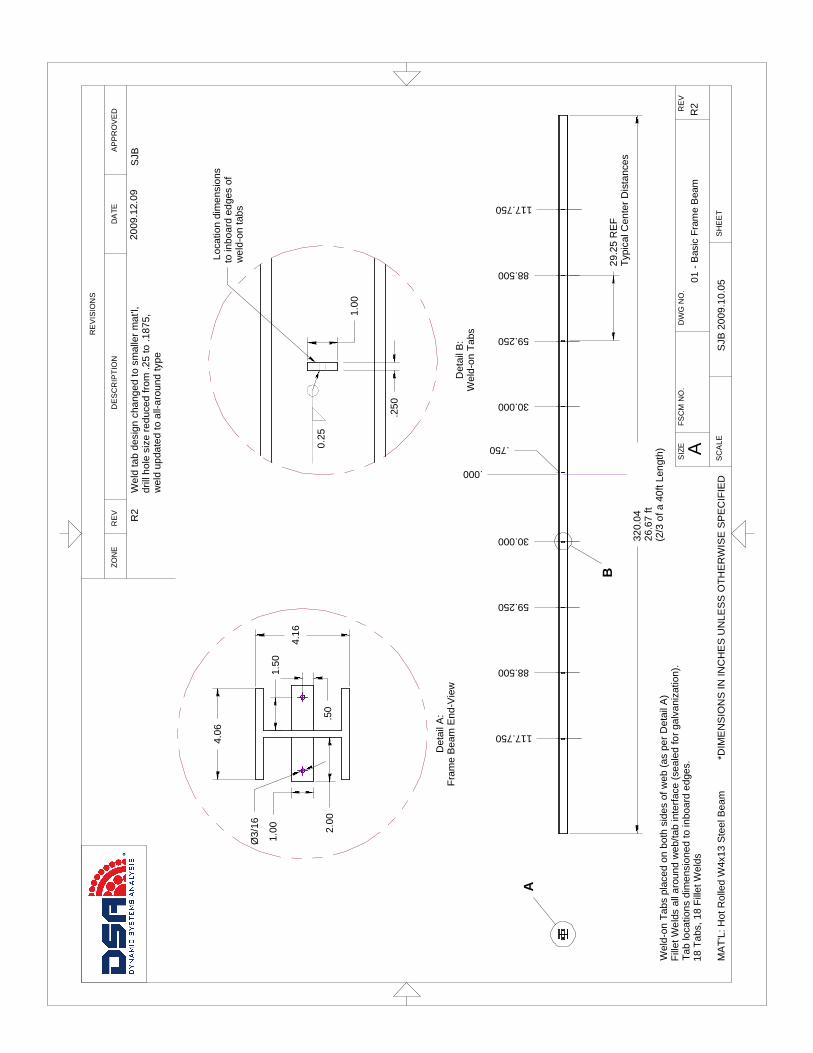
A
320.
0426
.67
ft (2
/3 o
f a 4
0ft L
engt
h)
29.2
5 R
EF
Typ
ical
Cen
ter
Dis
tanc
es
.000
.750
30.000
59.250
88.500
117.750
30.000
59.250
88.500
117.750
B
MA
T'L
: Hot
Rol
led
W4x
13 S
teel
Bea
mS
JB 2
009.
10.0
5
R2
Wel
d-on
Tab
s pl
aced
on
both
sid
es o
f web
(as
per
Det
ail A
)F
illet
Wel
ds a
ll ar
ound
web
/tab
inte
rfac
e (s
eale
d fo
r ga
lvan
izat
ion)
.T
ab lo
catio
ns d
imen
sion
ed to
inbo
ard
edge
s.18
Tab
s, 1
8 F
illet
Wel
ds
4.16
4.06
2.00
Ø3/
16
1.00
1.50
.50
Det
ail A
:F
ram
e B
eam
End
-Vie
w
.250
1.00
Det
ail B
:W
eld-
on T
abs
Loc
atio
n di
men
sion
s to
inbo
ard
edge
s of
w
eld-
on ta
bs
0.
25
01
- B
asic
Fra
me
Bea
m
DA
TEA
PP
RO
VE
DD
ES
CR
IPT
ION
SIZ
ER
EV
ZON
E
SC
ALE
DW
G N
O.
SH
EE
T
RE
V
FS
CM
NO
.
A
RE
VIS
ION
S
*DIM
EN
SIO
NS
IN IN
CH
ES
UN
LES
S O
TH
ER
WIS
E S
PE
CIF
IED
R2
2009
.12.
09S
JBW
eld
tab
desi
gn c
hang
ed to
sm
alle
r m
at'l,
drill
hol
e si
ze r
educ
ed fr
om .2
5 to
.187
5,
wel
d up
date
d to
all-
arou
nd ty
pe

320
Tw
o W
4x13
x 1
60in
segm
ents
spl
iced
at
mid
span
.
.000
30.000
59.250
88.500
117.750
30.000
59.250
88.500
117.750
.750
A A
AB
*ALL
DIM
EN
SIO
NS
IN IN
CH
ES
UN
LES
S O
TH
ER
WIS
E S
PE
CIF
IED
R2
SJB
2009
.12.
09
Sec
tion
A-A
Hot
Rol
led
W4x
13 S
teel
*Wel
d-on
Tab
s x
8,
only
on
one-
side
of
splic
ed b
eam
s
.2
5
Fla
nge
Spl
ice
Pla
tes
x 2
Hot
Rol
led
3/8
x 3.
5 x
16in
Det
ail A
Wel
d-on
tab
loca
tions
give
n to
inbo
ard
edge
sP
lace
men
t sym
met
ric a
bout
mid
-spa
n
.2
5
16.0
0
.375
.2
5
Det
ail B
: B
eam
Spl
ice
Wel
ded
butt
join
t: be
vele
d ed
ges
with
a 1
/8"
root
gap
100%
wel
d pe
netr
atio
n w
ith b
ack
grin
ding
.W
elde
d S
plic
e pl
ates
on
flang
es: 1
/4"
fille
t all
arou
nd
DA
TE
FS
CM
NO
.
AP
PR
OV
ED
SC
ALE
DE
SC
RIP
TIO
N
DW
G N
O.
RE
VIS
ION
S
RE
V
SH
EE
T
02
-Sp
liced
Fra
me
Bea
m-A
ssem
bly
AS
IZE
RE
VZO
NE
2009
.12.
09R
2B
olte
d sp
lice
chan
ged
to a
wel
ded
splic
e,
Web
spl
ice
plat
es r
emov
ed,
Fla
nge
splic
e pl
ates
red
uced
to 3
.5in
wid
th
SJB

3.50
16.0
0
All
drill
ed h
oles
rem
oved
, m
ater
ial w
idth
red
uced
from
4.5
to 3
.5in
to a
ccom
odat
e fil
let w
eld
RE
VIS
ION
S
RE
V
SIZ
E
ZON
E
DW
G N
O.
03
-Sp
lice
Fla
ng
e P
late
RE
VF
SC
M N
O.
AP
PR
OV
ED
A
DE
SC
RIP
TIO
N
SC
ALE
DA
TE
SH
EE
TM
AT
ER
IAL:
HO
T R
OLL
ED
3/8
x 4
.5 A
ST
M A
-36
Ste
el
*ALL
DIM
EN
SIO
NS
IN IN
CH
ES
UN
LES
S O
TH
ER
WIS
E S
PE
CIF
IED
2009
.08.
29S
JBR
1
R1
SJB
200
9.12
.09

.375
1.50
5.50
7.00
.328
RE
F
n27
/32"
(0.
8438
) T
HR
UT
YP
ICA
L x
2
RE
VIS
ION
S
DE
SC
RIP
TIO
N
AF
SC
M N
O.
ZON
E
SC
ALE
AP
PR
OV
ED R
EV
DA
TE
SIZ
ED
WG
NO
.
RE
V
05
- C
lam
p P
late
SH
EE
TA
LL D
IME
NS
ION
S IN
INC
HE
S
MA
T'L
: H
OT
RO
LLE
D A
ST
M A
-36
3/8
X 1
.5 S
TE
EL
SJB
200
9.12
.09
R2
Dril
led
hole
siz
es in
crea
sed
from
0.7
5 C
LR to
27/
32to
acc
omod
ate
galv
aniz
atio
n th
ickn
ess
2009
.12.
09S
JB
R2
