development of an autonomous underwater vehicle in an interdisciplinary context bernhard gerl
TRANSCRIPT
Development of an Autonomous Underwater Vehicle in an Interdisciplinary Context
Bernhard Gerl
Diploma Thesis / Diplomarbeit
Technische Universität München Fakultät für Maschinenwesen
The University of Western AustraliaSchool of Electrical, Electronic and Computer Engineering
Supervisors:Prof. Dr. Thomas Bräunl, UWA
Prof. Dr. Lindemann, TUM
2006

Table of Contents 1
TABLE OF CONTENTS 1 Introduction 3
1.1 Motivation 3
1.2 Outline of the thesis 3
2 Mechatronic systems 5
2.1 Definition of mechatronics 5
2.2 Difference between robotics and mechatronics 7
2.3 Challenges of a mechatronic development process 8
2.4 Process models 11
2.5 Development of a process model for the AUV-Project 14
2.6 Usage of methods in mechatronic design 16
3 Initial situation 17
3.1 Activities at the Mobile Robotics Lab 17
3.2 Previous underwater vehicle projects 19
3.3 The USAL-Submarine 20
4 Task specification 22
4.1 General 22
4.2 Requirements for the AUV project 23
5 Research on AUVs 26
5.1 AUVs in general 26
5.2 AUVs for high school competitions 27
5.3 Physical properties of AUVs 31 5.3.1 Coordinate system 31 5.3.2 Buoyancy, Stability 31 5.3.3 Pressure 32 5.3.4 Drag 33
6 Function structure 34
6.1 Functions structures for mechatronic systems 34
6.2 Development of function structures for the AUV 35
7 Concept design 40
7.1 General 40
7.2 Development of mechanical principle for the AUV 41
Table of Contents 2
7.2.1 Morphologic box with possible solutions 41 7.2.2 Comparison of two concepts 43 7.2.3 Development of new concept for AUV 45 7.2.4 Variations of possible solutions 46
7.3 Actuators 49 7.3.1 General 49 7.3.2 Actuators for the AUV 50
7.4 Sensors 51 7.4.1 General 51 7.4.2 Sensors for the AUV 52
7.5 Further electronic components 58 7.5.1 Camera 59 7.5.2 Battery 59 7.5.3 Bluetooth communicator 59 7.5.4 Infrared sensor 59
8 Domain-specific design 60
8.1 Mechanical Design 60 8.1.1 General 60 8.1.2 Mechanical design of the AUV 61
8.2 Electronic Design 63 8.2.1 General 63 8.2.2 Electronic design for AUV 63
8.3 Software Design 65 8.3.1 General 65 8.3.2 Software for AUV 66
9 Conclusion 67
9.1 Reflection on the development process 67
9.2 Future work and recommendations 68
9.3 Final word 69
10 References 70
11 Appendix 74
Photos of AUV parts 74
Photos of the mechanical design 77
Task of an AUV competition 80
1 Introduction 3
1 Introduction
1.1 Motivation The word mechatronic, uncommon a century ago, is now used everywhere. New mechatronic study paths have been established in universities and engineers with interdisciplinary skills are in demand. The increasing coalescence of formerly separated disciplines imposes new challenges to the engineers involved in the development of mechatronic products. Higher complexity of the products, cooperation in interdisciplinary teams and shorter development times are but a few examples for these challenges.
The author had the chance to carry out a mechatronic development project at the Mobile Robotics Lab at University of Western Australia in Perth. Every year universities all over the world are competing in underwater high school competition, with custom made Autonomous Underwater Vehicles (AUV). The Robotic Lab is aiming to participate with a small submarine in the future. The task of the author was to develop a concept for an AUV that is smaller and cheaper than existing ones.
The development of the AUV is presented as an example of the development process for a mechatronic product. The difficulties occurring in such a process are discussed, possible methods and process models to overcome these problems are proposed and used.
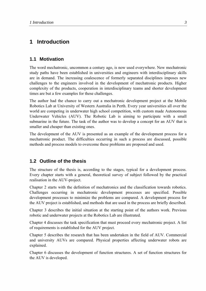
1.2 Outline of the thesis The structure of the thesis is, according to the stages, typical for a development process. Every chapter starts with a general, theoretical survey of subject followed by the practical realisation in the AUV-project.
Chapter 2 starts with the definition of mechatronics and the classification towards robotics. Challenges occurring in mechatronic development processes are specified. Possible development processes to minimize the problems are compared. A development process for the AUV project is established, and methods that are used in the process are briefly described.
Chapter 3 describes the initial situation at the starting point of the authors work. Previous robotic and underwater projects at the Robotics Lab are illustrated.
Chapter 4 discusses the task specification that must proceed every mechatronic project. A list of requirements is established for the AUV project.
Chapter 5 describes the research that has been undertaken in the field of AUV. Commercial and university AUVs are compared. Physical properties affecting underwater robots are explained.
Chapter 6 discusses the development of function structures. A set of function structures for the AUV is developed.
1 Introduction 4
Chapter 7 describes the concept design of the AUV. Several methods are used to come up with an optimum solution. At first a mechanical principle for the design of the AUV is chosen. then sensors and actuators and further electric components are determined.
Chapter 8 discusses the domain-specific design in the mechanical, electronic and software discipline.
Chapter 9 reflects the whole development process and gives an overview of the methods used.
2 Mechatronic systems 5
2 Mechatronic systems In this chapter the term mechatronics is defined and distinguished from the term robotics. The difficulties in the development of mechatronic products, and possible development processes to prevent those difficulties, are described.
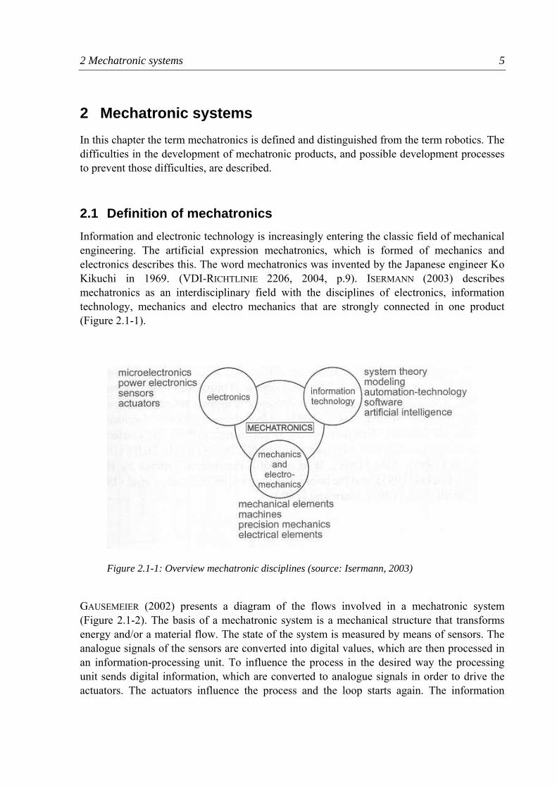
2.1 Definition of mechatronics Information and electronic technology is increasingly entering the classic field of mechanical engineering. The artificial expression mechatronics, which is formed of mechanics and electronics describes this. The word mechatronics was invented by the Japanese engineer Ko Kikuchi in 1969. (VDI-RICHTLINIE 2206, 2004, p.9). ISERMANN (2003) describes mechatronics as an interdisciplinary field with the disciplines of electronics, information technology, mechanics and electro mechanics that are strongly connected in one product (Figure 2.1-1).
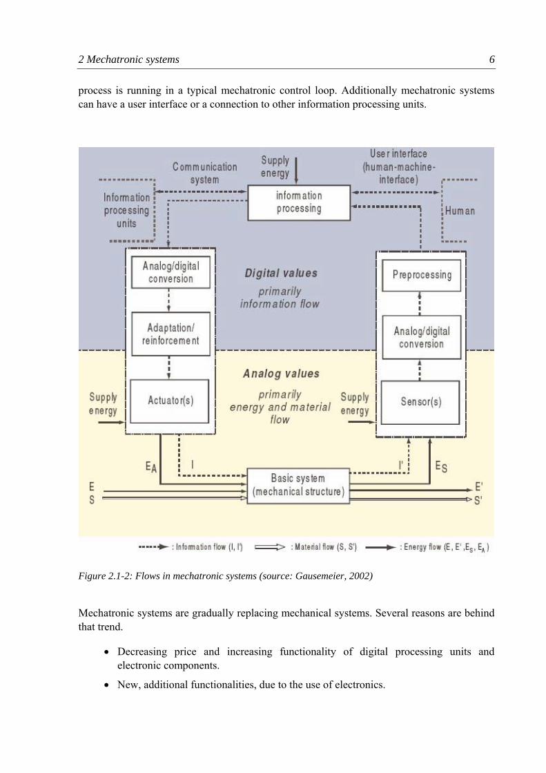
GAUSEMEIER (2002) presents a diagram of the flows involved in a mechatronic system (Figure 2.1-2). The basis of a mechatronic system is a mechanical structure that transforms energy and/or a material flow. The state of the system is measured by means of sensors. The analogue signals of the sensors are converted into digital values, which are then processed in an information-processing unit. To influence the process in the desired way the processing unit sends digital information, which are converted to analogue signals in order to drive the actuators. The actuators influence the process and the loop starts again. The information
Figure 2.1-1: Overview mechatronic disciplines (source: Isermann, 2003)
2 Mechatronic systems 6
process is running in a typical mechatronic control loop. Additionally mechatronic systems can have a user interface or a connection to other information processing units.
Mechatronic systems are gradually replacing mechanical systems. Several reasons are behind that trend.
• Decreasing price and increasing functionality of digital processing units and electronic components.
• New, additional functionalities, due to the use of electronics.
Figure 2.1-2: Flows in mechatronic systems (source: Gausemeier, 2002)
2 Mechatronic systems 7
• Mechatronic systems are lighter and simpler, as they replace complex mechanics that had to control or steer a system before.
• Mechatronic systems can be easily adjusted by changing the software.
• The possibility to generate independent modules reduces the complexity of extensive systems.
• User interfaces enable the direct supervision and interaction with the system by a supervisor.
As the mechatronic products integrate functionalities, modules and elements of several disciplines, engineers of these disciplines have to cooperate close. This requires:
• Communication between formerly separated departments in companies.
• Interdisciplinary education of engineers.
• Integrating of formerly separated development processes.
• Methods to handle the increasing complexity.
2.2 Difference between robotics and mechatronics This thesis was written at the Robotics Lab at the UWA. The main research areas at that Lab are applications of mobile robotics. To prevent the mixing of the concepts of robotics and mechatronics a brief classification is given, as both terms are not the same. In the scientific literature several definition of robots or robotics could be found.
A definition is given by SHAHIPOOR (1987, p.2):
„A Robot is a reprogrammable multifunctional manipulator designed to move materials, parts, tools or specialized devices, through variable programmed motions for the performance of a variety of tasks.”
Two major fields of robots can be found. On the one side the classic industrial robot, for example in the assembly line of a car manufacturer, on the other side autonomous vehicles like mars rovers, walking robots and wheeled robots. These robots can also be defined as mechatronic systems, as they consist of mechanical and electronic elements, and are controlled by a information processing unit. The use of sensors and actuators is typical for a mechatronic system.
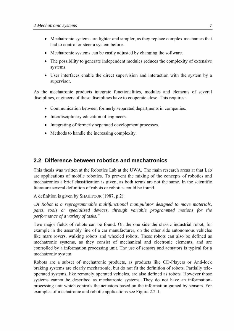
Robots are a subset of mechatronic products, as products like CD-Players or Anti-lock braking systems are clearly mechatronic, but do not fit the definition of robots. Partially tele-operated systems, like remotely operated vehicles, are also defined as robots. However those systems cannot be described as mechatronic systems. They do not have an information-processing unit which controls the actuators based on the information gained by sensors. For examples of mechatronic and robotic applications see Figure 2.2-1.
2 Mechatronic systems 8
In the following the focus will be on the term mechatronics. The autonomous underwater vehicle described in this paper, is a typical mechatronic system. It uses sensors and actuators and an information-processing unit to control a mechanical process.
2.3 Challenges of a mechatronic development process According to BERNARDI ET AL.(2004, p.1) the development process of a mechatronic system is characterized by a much higher complexity, more parameters and a larger quantity of data compared to the classic discipline-separated development process.
WEBER (2005) proposes an extended concept of complexity with five main dimensions:
• Numerical complexity
• Relational/structural complexity
• Variational complexity
• Disciplinary complexity
• Organisational complexity
Figure 2.2-1: Examples for mechatronic and robotic systems
2 Mechatronic systems 9
Mechatronic products tend to be complex in all of those five dimensions. They involve a large number of elements that are related in numerous ways. The variational complexity can be high if the product is a sub-module of a versatile product. As an example an anti-lock braking system can be used in a large number of different cars, if varied according to the applied car. The disciplinary complexity of mechatronic developments is obviously high, due to the involvement of several disciplines. The organisational complexity can be high depending on the distribution of the work.
A differing concept of complexity is given by FELGEN (2005, p.2) with the following impacts:
• Number of elements and relations
• Diversity of elements and relations
• Number and diversity of states
A system can be structural and behavioural complex . A high number of element and relations leads to structural complexity. With high number and diversity of states a system gets difficult to predict or behavioural complex. According to Felgen mechatronic systems tend to be complex out of three reasons:
• Interdisciplinarity leads to higher diversity of elements and relations.
• The high degree in cross-linkings is on par with a high number of relations.
• The flexibility in terms of increasing functionality increases the behavioural complexity.
Both definitions show the high complexity of mechatronic products. To cope with this complexity systematic analysis and development of function structures of the system is necessary (Chapter 6).
Due to the high complexity in products are generally developed in interdisciplinary teams. This however may lead to several difficulties:
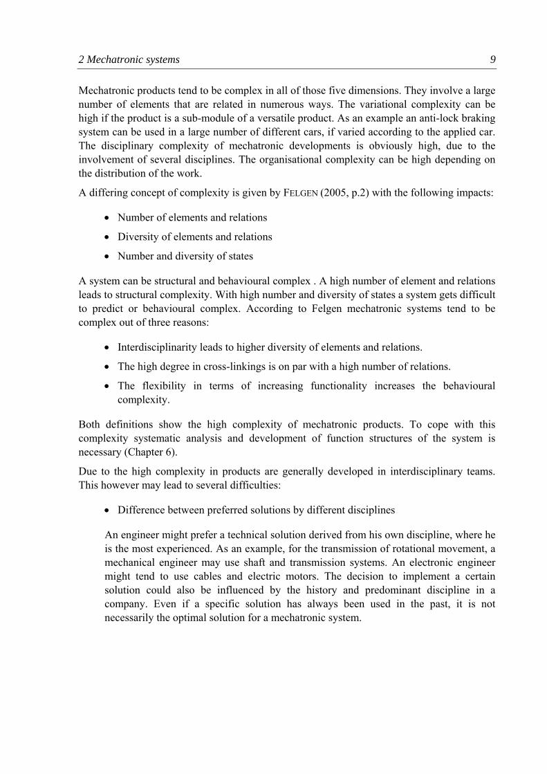
• Difference between preferred solutions by different disciplines
An engineer might prefer a technical solution derived from his own discipline, where he is the most experienced. As an example, for the transmission of rotational movement, a mechanical engineer may use shaft and transmission systems. An electronic engineer might tend to use cables and electric motors. The decision to implement a certain solution could also be influenced by the history and predominant discipline in a company. Even if a specific solution has always been used in the past, it is not necessarily the optimal solution for a mechatronic system.
2 Mechatronic systems 10
• Different methods of notation
Over the years each discipline has developed different ways of notation, which are not compatible with other disciplines. As an example the mechanical engineer uses an engineering drawing to determine the spatial properties of his design. Electric components, like wires, however are not shown in these drawings. An electrical engineer uses two-dimensional circuit diagrams that show the elements of his circuit design, but not the spatial requirements. With increasing miniaturisation the necessity for a integrated method of notation increases. One possibility is the use of wiring tools in CAD-systems that help to integrate electric cabling (LINDFORS ET AL, 2003).
• Different “languages”
Each discipline has a different “language”, as it uses different expressions for the elements it is dealing with. Physical formulas and variables differ in the disciplines, even if they express a similar effect. An engineer might have problems understanding a solution in another discipline, because he is not trained in that “language”, even if he can understand the physical principle behind the idea.
ISERMANN (2003) outlines how to find a general way of describing a mechatronic system. He defines terms like “flow” (e.g. electric current, speed, volume flow) or “potential difference” (e.g. electric voltage, power, pressure difference). As an example a “storage element” in a system can be a spring (mechanical) or a capacitor (electrical). The basic physical principle behind a “storage element” is the same. The difference is stored proportional to the accumulated flow. The relationship between the effects in two different areas of engineering can be seen clearly. An engineer trained in this general way of thinking and talking of technical systems might cross the borders of his discipline easier.
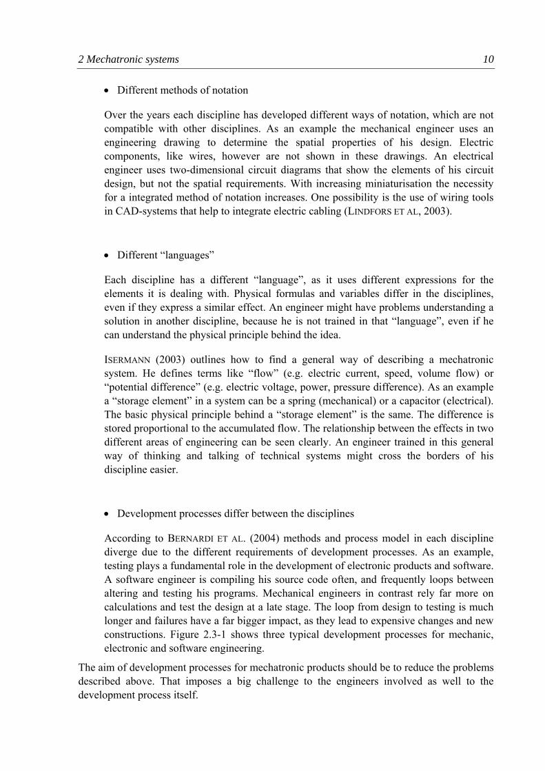
• Development processes differ between the disciplines
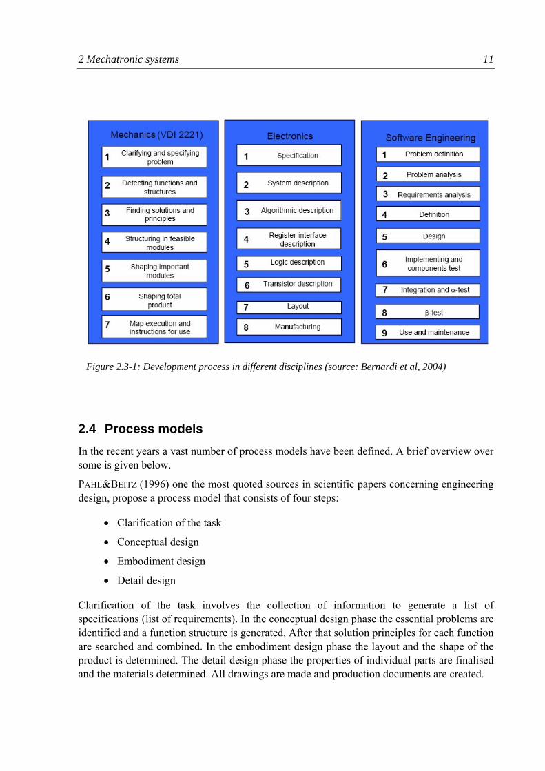
According to BERNARDI ET AL. (2004) methods and process model in each discipline diverge due to the different requirements of development processes. As an example, testing plays a fundamental role in the development of electronic products and software. A software engineer is compiling his source code often, and frequently loops between altering and testing his programs. Mechanical engineers in contrast rely far more on calculations and test the design at a late stage. The loop from design to testing is much longer and failures have a far bigger impact, as they lead to expensive changes and new constructions. Figure 2.3-1 shows three typical development processes for mechanic, electronic and software engineering.
The aim of development processes for mechatronic products should be to reduce the problems described above. That imposes a big challenge to the engineers involved as well to the development process itself.
2 Mechatronic systems 11
2.4 Process models In the recent years a vast number of process models have been defined. A brief overview over some is given below.
PAHL&BEITZ (1996) one the most quoted sources in scientific papers concerning engineering design, propose a process model that consists of four steps:
• Clarification of the task
• Conceptual design
• Embodiment design
• Detail design
Clarification of the task involves the collection of information to generate a list of specifications (list of requirements). In the conceptual design phase the essential problems are identified and a function structure is generated. After that solution principles for each function are searched and combined. In the embodiment design phase the layout and the shape of the product is determined. The detail design phase the properties of individual parts are finalised and the materials determined. All drawings are made and production documents are created.
Figure 2.3-1: Development process in different disciplines (source: Bernardi et al, 2004)
2 Mechatronic systems 12
The design process proposed by Pahl&Beitz provides the basis for the guideline VDI 2222. The process structure is linear, however loops backwards are possible. The process is particularly applicable to the development of mechanical products. The process model is not necessarily useful to the complete development of a mechatronic product, as electronic and software design need a different process models. For instance extensive testing-phases, necessary for electronic products and software, are not part of the process model.
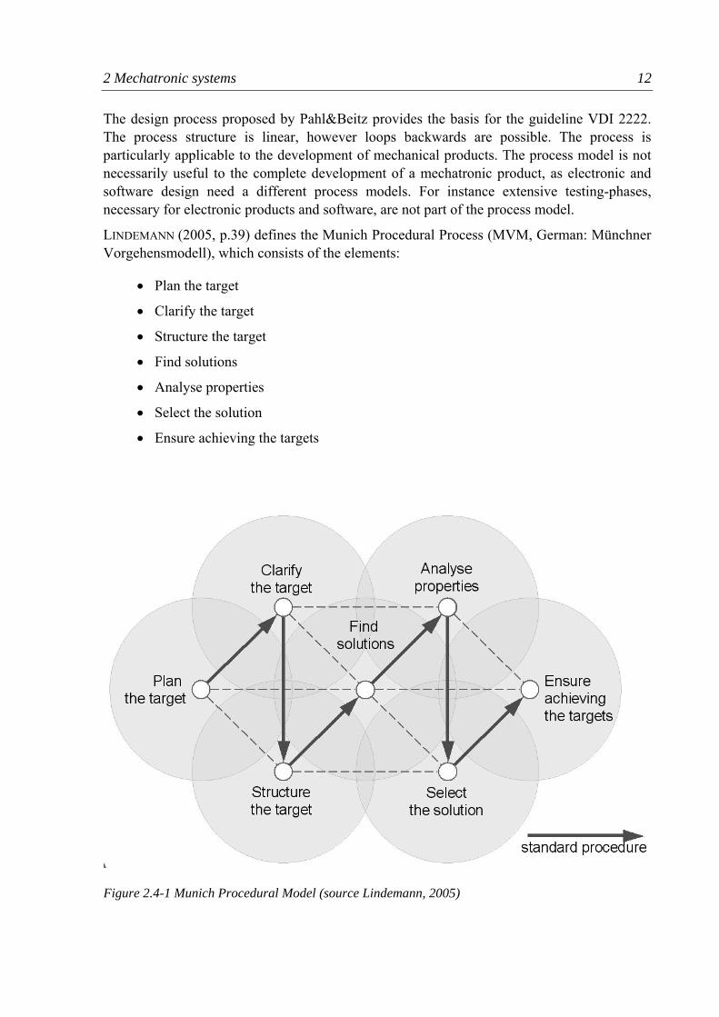
LINDEMANN (2005, p.39) defines the Munich Procedural Process (MVM, German: Münchner Vorgehensmodell), which consists of the elements:
• Plan the target
• Clarify the target
• Structure the target
• Find solutions
• Analyse properties
• Select the solution
• Ensure achieving the targets
Figure 2.4-1 Munich Procedural Model (source Lindemann, 2005)
2 Mechatronic systems 13
The elements can be used in a flexible and non-linear way. The whole process can be traversed several times or in a recursive way primarily for the concept design and secondly for the embodiment design. The elements can also be found in Pahl&Beitz process model, in the concept design phase. The MVM is an orientation guide for solving problems, but not a formula that has to be followed step by step. The MVM is not especially designed for the development of a mechatronic product, however, the basic elements can be found in most development processes. GAUSEMEIER (2002) chairman of the committee for the VDI-Guideline 2206: “Design methodology for mechatronic systems”, promotes a process model for mechatronics that is based on two procedural models.
• The problem-solution cycle as a microcyle: consists of the two elements of analysis and synthesis, which the developer goes through in multiple cases in conscious or unconscious way.
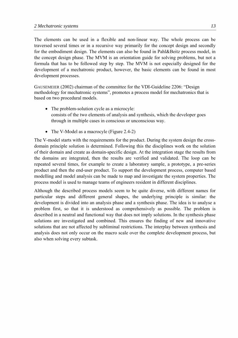
• The V-Model as a macrocyle (Figure 2.4-2)
The V-model starts with the requirements for the product. During the system design the cross-domain principle solution is determined. Following this the disciplines work on the solution of their domain and create as domain-specific design. At the integration stage the results from the domains are integrated, then the results are verified and validated. The loop can be repeated several times, for example to create a laboratory sample, a prototype, a pre-series product and then the end-user product. To support the development process, computer based modelling and model analysis can be made to map and investigate the system properties. The process model is used to manage teams of engineers resident in different disciplines.
Although the described process models seem to be quite diverse, with different names for particular steps and different general shapes, the underlying principle is similar: the development is divided into an analysis phase and a synthesis phase. The idea is to analyse a problem first, so that it is understood as comprehensively as possible. The problem is described in a neutral and functional way that does not imply solutions. In the synthesis phase solutions are investigated and combined. This ensures the finding of new and innovative solutions that are not affected by subliminal restrictions. The interplay between synthesis and analysis does not only occur on the macro scale over the complete development process, but also when solving every subtask.
2 Mechatronic systems 14
2.5 Development of a process model for the AUV-Project The development of the AUV differs from the previously described processes, which are aimed at team projects. The author is working alone for the bulk of the project, so the necessity of coordinating a team is not present. However in a later stage of the development further students enter the project and carry it on. The experience of the author is mainly in the field of mechanical engineering. The mechanical part and its development has a greater emphasis. The funding for the project is relatively small, so not necessarily the best technical solution can be used.
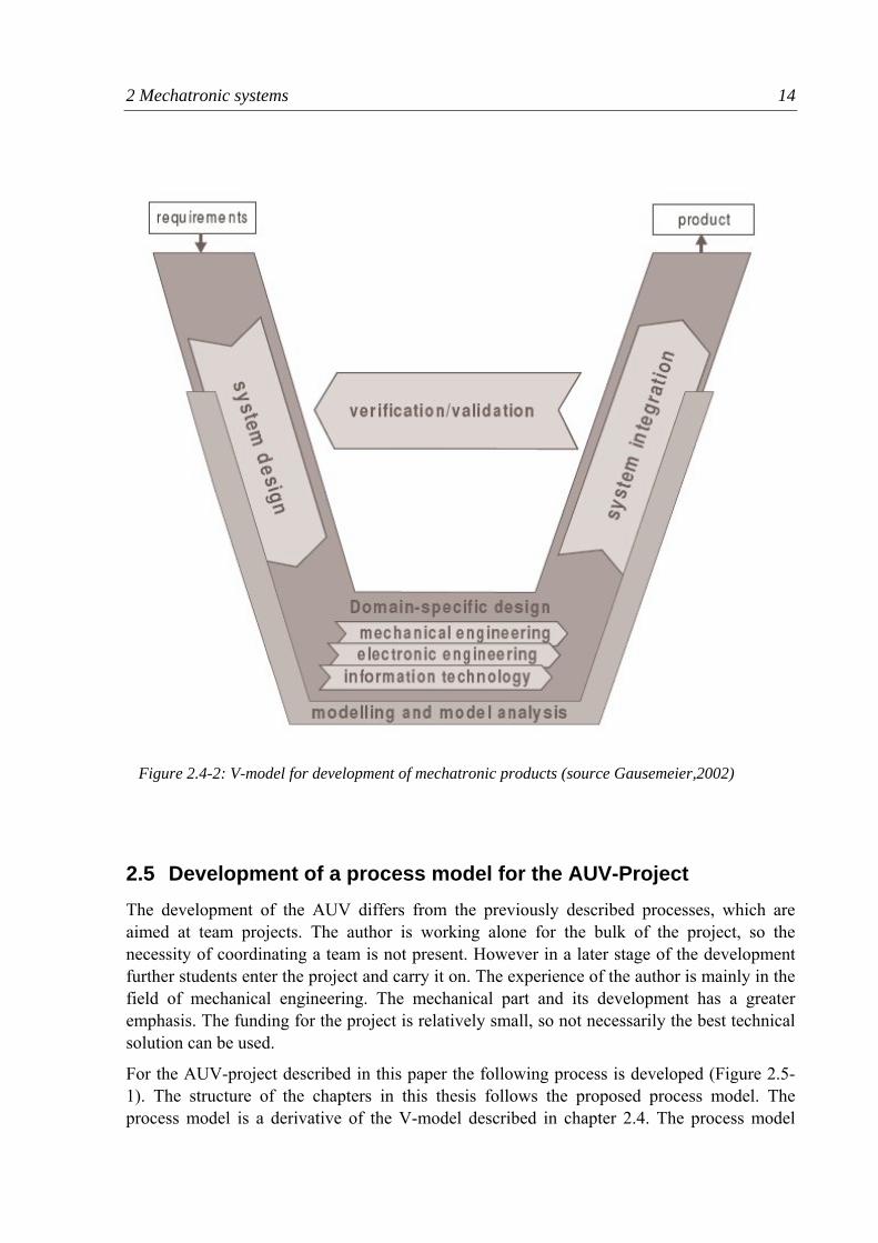
For the AUV-project described in this paper the following process is developed (Figure 2.5-1). The structure of the chapters in this thesis follows the proposed process model. The process model is a derivative of the V-model described in chapter 2.4. The process model
Figure 2.4-2: V-model for development of mechatronic products (source Gausemeier,2002)
2 Mechatronic systems 15
consists of two main phases, the analysis and the synthesis phase. First the initial situation is clarified and described. After that research concerning the extensive field of AUV is done. Then function structures are set up in order to analyse and describe the AUV.
The synthesis phase starts with the concept design. Solutions for each pre-determined function are found and combined. A general mechanical principle is chosen. Sensors and actuators are examined and chosen. After that the design process divides into the several disciplines, where the specific detail design is done. This section is called domain-specific
Figure 2.5-1: Process model for AUV-project
2 Mechatronic systems 16
design according to the V-model. After the fabrication of the mechanical parts and the electronic circuits, the parts are assembled. The software is programmed and implemented. The last step will be the testing of the AUV and the calibrating of the sensors and actuators.
In contrast to the V-model a stronger emphasis is laid on the separation of the analysis and synthesis phase and additionally the “initial situation” and “research” are added as they take a bigger part of the thesis. The development process in the thesis runs through the cycle only once, but it is possible to repeat the process for further improvements and modifications of the AUV. Besides the macro-cycle of the whole process, micro-cycles with analysis and synthesis occur over the entire development process.
2.6 Usage of methods in mechatronic design Not only can the use of a process model help to improve the quality of results in a development process, but also the reasonable use of methods.
LINDEMANN (2005) defines a method as the description of a schedule procedure based on rules. Certain activities have to be accomplished by following the description. In comparison to the process model, methods have a more operative character. In this thesis the following methods are used and adapted:
• List of requirements
• Flow-oriented function structure
• Hierarchical function structure
• Morphologic box
• Variation methods
• Comparison of advantages and disadvantages
• Weighted rating
Most methods can easily be used in mechatronic development, some have to be adapted. An overview and assessment of the methods used is given at the end in chapter 9.1.
3 Initial situation 17
3 Initial situation The initial situation at the beginning of the AUV development, the activities in the Mobile Robotics Lab at the University of Western Australia (UWA) and the previous achievements in underwater vehicle projects are described.
3.1 Activities at the Mobile Robotics Lab This thesis is written at the Mobile Robotics Lab, which is part of the Department of Electrical and Electronic Engineering at the University of Western Australia (UWA) in Perth. The Mobile Robotics Lab is headed by A/Prof. Thomas Bräunl.
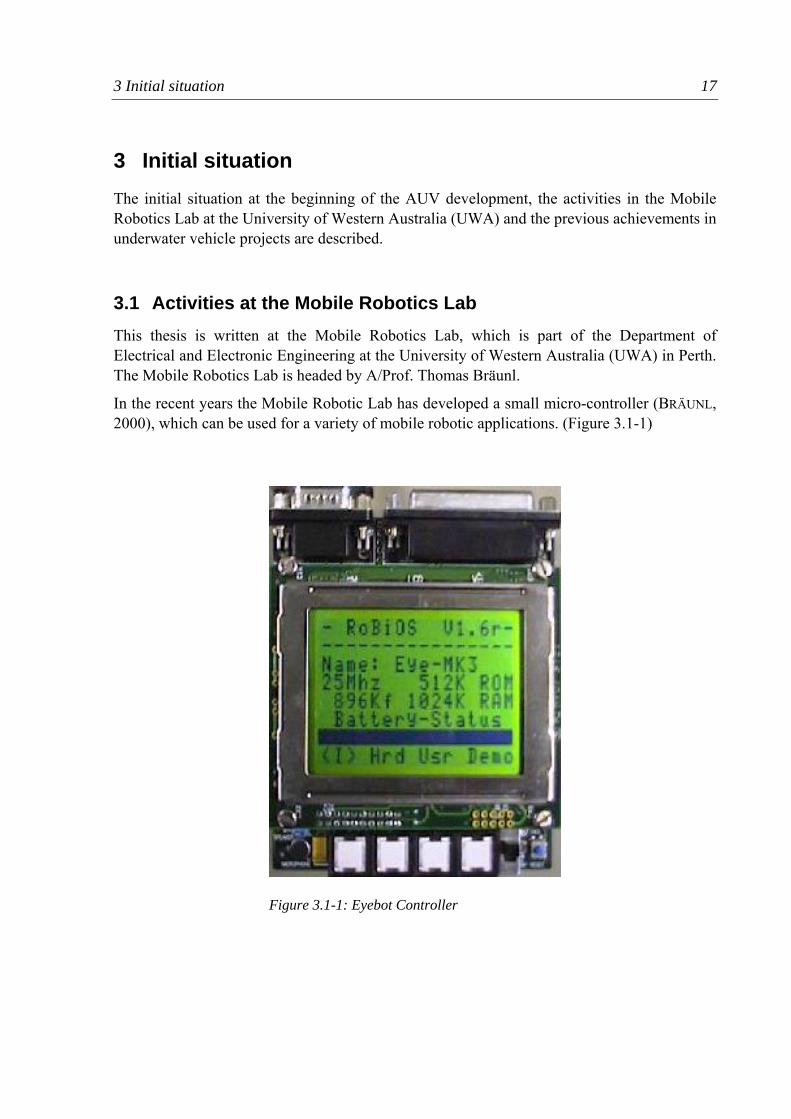
In the recent years the Mobile Robotic Lab has developed a small micro-controller (BRÄUNL, 2000), which can be used for a variety of mobile robotic applications. (Figure 3.1-1)
Figure 3.1-1: Eyebot Controller
3 Initial situation 18
Some features of the Eyebot controller are:
• straight-forward programming in C or assembler
• analogue and digital inputs for sensors
• analogue and digital outputs for actuators
• a LCD-display
• programs can be written in C++ on a PC and uploaded via serial line
• specific functions in the BIOS of the controller enable direct and easy programming
• possibility to attach a digital colour camera
In the recent years student project have designed several mobile robotic applications.(MOBILE ROBOT LAB, 2005). For example biped and six-legged walking-robots, balancing robots, an autonomous model plane and driving robots. The Eyebot is also used for teaching in small scale programming tasks, like finding an object with a driving robot.
Parallel to the hardware development a software simulation system, called EyeSim, was developed. With EyeSim simulated robots can be programmed and tested on a computer before being applied to a real robot. Additionally a simulation software, called SubSim, is programmed at the moment.
3 Initial situation 19
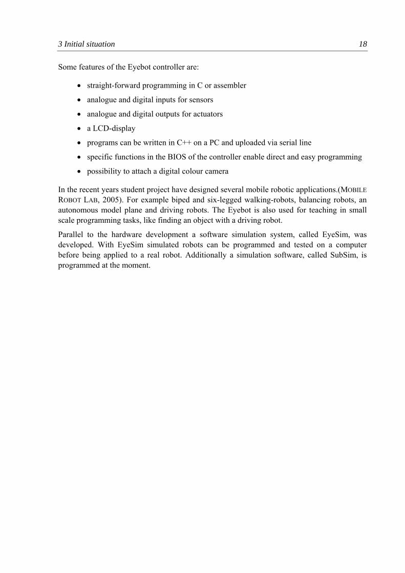
3.2 Previous underwater vehicle projects In the year 2004 a group of three final-year students developed an autonomous underwater vehicle, called Mako (Figure 3.2-1).
GONZALES (2004) describes the construction of the Mako submarine. The AUV is about 1.5m long and weighs 35kg. It consists of two PVC-hulls, which protect the electronic components, an Eyebot-Controller and a MiniPC for fast image processing. The two hulls are mounted on an aluminium frame that supports four electrical outboard motors-propeller combinations. Two propellers at the stern and at the bow push the AUV under water, as it is slightly positive buoyant. Two propellers are mounted horizontally on both sides of the AUV. These propellers are used for the forward and backward movement as well as for yaw movement.
A paddle wheel sensor determines the speed and a digital compass measures the direction of the Mako. Sonar sensors detect the distance to walls and to the ground. A digital camera looking downward can be used to detect objects on the ground. A Bluetooth module enables direct communication to a PC or a mobile phone when on the surface. The AUV is designed for applications in swimming pools and is capable to dive to a depth up to 5m. The purpose of the AUV is to compete in national and international varsity competitions. These competitions are held regularly, for example by the Association for Unmanned Vehicle Systems International (AVUSI, 2005). Typical tasks in these competitions are:
Figure 3.2-1: Mako-AUV
3 Initial situation 20
• Following a wall
• Finding an object on the pool floor
• Driving through a gate
• Dropping of an obstacle on a certain spot
However these competitions are held in the USA and a transport of the bulky vehicle is very costly. At the time of writing this paper, the constructive part of the AUV Mako is completed. Most sensors are applied and work. The AUV can be remotely controlled, but the software for autonomous control is not yet implemented.
3.3 The USAL-Submarine The biggest disadvantage of the Mako is its bulkiness and weight, which makes it very impractical and expensive for transportation from Perth to international or even national competitions. So the idea is to build a second, smaller and lighter AUV.
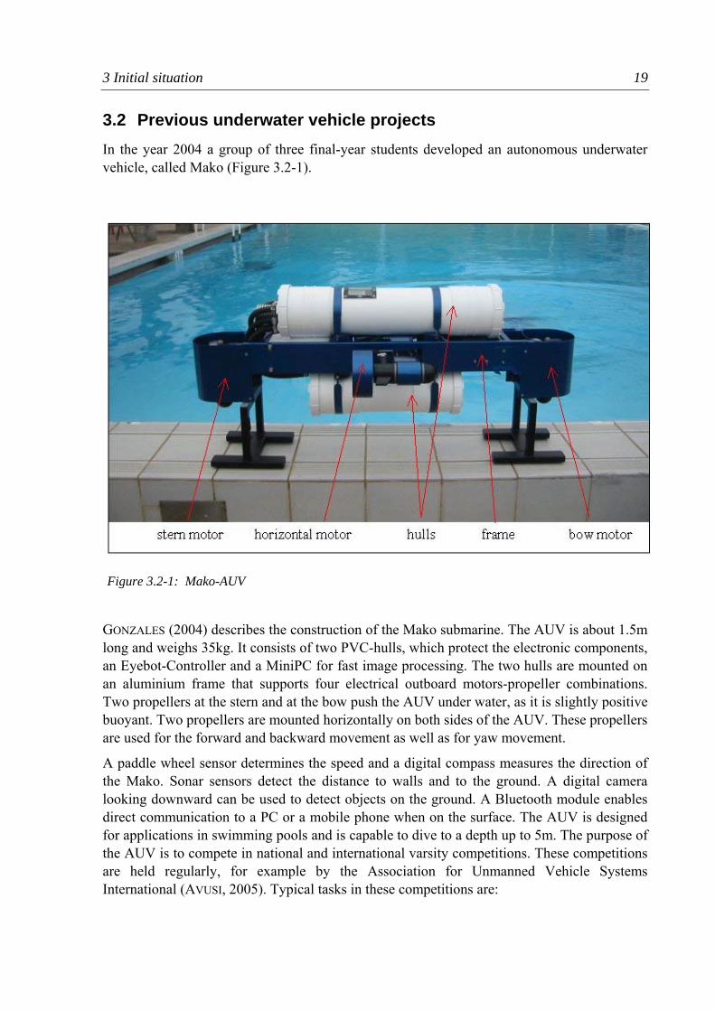
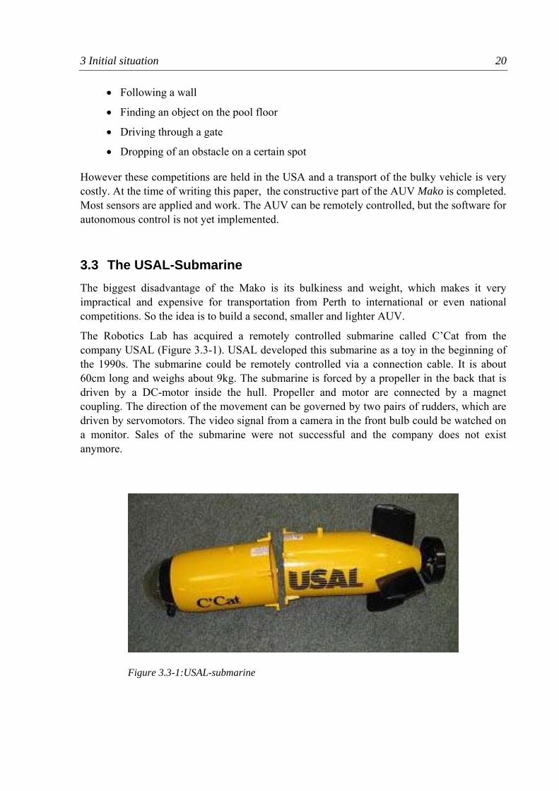
The Robotics Lab has acquired a remotely controlled submarine called C’Cat from the company USAL (Figure 3.3-1). USAL developed this submarine as a toy in the beginning of the 1990s. The submarine could be remotely controlled via a connection cable. It is about 60cm long and weighs about 9kg. The submarine is forced by a propeller in the back that is driven by a DC-motor inside the hull. Propeller and motor are connected by a magnet coupling. The direction of the movement can be governed by two pairs of rudders, which are driven by servomotors. The video signal from a camera in the front bulb could be watched on a monitor. Sales of the submarine were not successful and the company does not exist anymore.
Figure 3.3-1:USAL-submarine
3 Initial situation 21
The robotics lab was provided with one of these submarines at no costs. The batteries, the camera and parts of the electronic were missing. A translucent front part of the submarine could also be acquired as well. The stern propellers were working. The servomotors for the rudders however were too weak to overcome the friction in the bearings. Lead weights and a rack that holds them were delivered with the submarine and could be used for trimming.
The concept of the development project described in this paper is to use this submarine and modify it, so it can be used for an autonomous underwater competition.
4 Task specification 22
4 Task specification At the beginning of a project the task has to be specified. The problems involved in organizing the requirements are described. A list of requirements is developed for the AUV project.
4.1 General According to PAHL&BEITZ (1996, p.130) the clarification of the design task is essential for the subsequent development process. The task must be defined as fully and clearly as possible. All essential requirements have to be written down in order to avoid high cost or delays due to late modifications.
This is more relevant for the development of a mechatronic product because the involvement of several disciplines and the amount of interfaces leads to a high complexity. The common target for the development team has to be clear for every member.
The following questions have to be answered:
• What is the problem really about?
• What implicit wishes and expectations are involved?
• Do the specific constraints actually exist?
• Which paths are open for development?
Requirements for a development project can be acquired by numerous ways.
LINDEMANN (2005, P.84) describes that vast amount of information are already present as implicit knowledge of the involved designers. The challenge is to verbalise this knowledge and to write it down in a systematic way, e.g. by using question techniques. Another possibility is the use of specific checklists, for establishing requirements. Especially in mechanical design, dominated by norms, a vast amount of requirements are implicit. In software design, as a relatively new discipline, standards are less common or yet to be developed. This makes it more difficult to find the necessary requirements.
In mechatronic design, due to the higher complexity (Chapter 2.3), one requirement can affect differently the elements and relations depending on their discipline. It is harder to anticipate the effect of a requirement and changes of requirments. For example in chapter 4.2 a requirement determines the minimum running time of the AUV. To reach this target, it is possible to reduce the drag of the AUV (mechanical design), to use efficient motors and amplifiers (electric design) and to use efficient control strategies (software design). Often solutions have to be combined to fulfil a requirement.
The common way to write down the specification in a systematic way is the list of requirements. The requirements are drawn up in a qualitative and, if possible, quantitative
4 Task specification 23
way. The requirements however should not imply a solution which would inhibit the search for innovative solutions.
PAHL&BEITZ (1996, p.142) points out the necessity to formulate the problem in a solution-neutral sentence, that comprises the abstract specifications of the task. In doing this, the objective is defined on an abstract level, without laying down any particular solution. For the development of a mechatronic product this could prevent inappropriate solutions, which are chosen because:
• they are in the discipline of a particular engineer
• they have been chosen in a similar case before
• they are implied by the imprecise requirements
The formulation of the problem should be done after the establishment of the requirements. It is a short, condensed and challenging version of the requirements.
4.2 Requirements for the AUV project As described above the Mako-AUV has a big disadvantage, as it is relatively bulky and heavy. The small USAL-Submarine is available, so the idea is to use this shell as a basis to build a second, cheaper and smaller AUV. The budget for the project, with less then AUD1000 small compared to other AUV projects. The aim is to find innovative solutions that solve this task. As the author is a mechanical engineer and the development of an AUV is a longer task, that requires a lot of work, the project of the author is constricted to the mechanical design, the selection of the electronic equipment and the assembly of the parts. The writing of the software is reduced to basic driving manoeuvres. The development of the control software and the camera software is not part of the project.
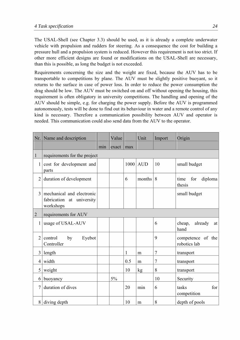
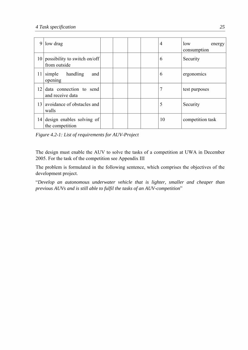
A list of requirements is set up to write down all necessary requirements (Figure 4.2-1). The list of requirements comprises of the columns: Nr, description, value, unit, importance and origin. In order to find the necessary requirements, a checklist is used (PAHL/BEITZ, 1996, p.133). This checklist covers a range of requirements arranged in topics and can help to find the necessary requirements. For example under the topic “geometry” one can find the requirement “length”, which is added in the list of requirements.
The first part of the list of requirements consists of the economical and organisational requirements of the project, like maximum costs or the tasks that should be done by the author. The second part of the list comprises the requirements the AUV has to fulfil.
The budget of the robot lab is used for several projects, so the maximum cost of the AUV is relatively small. An electronic and a mechanical workshop in the department are available to help with the fabrication of electronic and mechanical components.
For controlling the AUV the Eyebot-Controller has to be used, on the one hand because it comes without costs, the programming is straight-forward and it is small, on the other hand because Prof. Bräunl is looking for applications for the product of his lab.
4 Task specification 24
The USAL-Shell (see Chapter 3.3) should be used, as it is already a complete underwater vehicle with propulsion and rudders for steering. As a consequence the cost for building a pressure hull and a propulsion system is reduced. However this requirement is not too strict. If other more efficient designs are found or modifications on the USAL-Shell are necessary, than this is possible, as long the budget is not exceeded.
Requirements concerning the size and the weight are fixed, because the AUV has to be transportable to competitions by plane. The AUV must be slightly positive buoyant, so it returns to the surface in case of power loss. In order to reduce the power consumption the drag should be low. The AUV must be switched on and off without opening the housing, this requirement is often obligatory in university competitions. The handling and opening of the AUV should be simple, e.g. for charging the power supply. Before the AUV is programmed autonomously, tests will be done to find out its behaviour in water and a remote control of any kind is necessary. Therefore a communication possibility between AUV and operator is needed. This communication could also send data from the AUV to the operator.
Nr. Name and description Value Unit Import Origin
min exact max
1 requirements for the project
1 cost for development and parts
1000 AUD 10 small budget
2 duration of development 6 months 8 time for diploma thesis
3 mechanical and electronic fabrication at university workshops
small budget
2 requirements for AUV
1 usage of USAL-AUV 6 cheap, already at hand
2 control by Eyebot Controller
9 competence of the robotics lab
3 length 1 m 7 transport
4 width 0.5 m 7 transport
5 weight 10 kg 8 transport
6 buoyancy 5% 10 Security
7 duration of dives 20 min 6 tasks for competition
8 diving depth 10 m 8 depth of pools
4 Task specification 25
9 low drag 4 low energy consumption
10 possibility to switch on/off from outside
6 Security
11 simple handling and opening
6 ergonomics
12 data connection to send and receive data
7 test purposes
13 avoidance of obstacles and walls
5 Security
14 design enables solving of the competition
10 competition task
Figure 4.2-1: List of requirements for AUV-Project
The design must enable the AUV to solve the tasks of a competition at UWA in December 2005. For the task of the competition see Appendix III
The problem is formulated in the following sentence, which comprises the objectives of the development project.
“Develop an autonomous underwater vehicle that is lighter, smaller and cheaper than previous AUVs and is still able to fulfil the tasks of an AUV-competition”
5 Research on AUVs 26
5 Research on AUVs Before starting the design of an AUV, research has to be done on the field of underwater vehicles.
5.1 AUVs in general According to YUH (2000) most unmanned underwater vehicle are tethered and remotely operated. They are referred to as Remotely Operated Vehicles (ROV). Most of them are equipped with manipulators and can be used for purposes like maintenance of oilrigs. Due to the high operation cost and constriction by the tether extensive use of ROVs is restricted.
The demand for advanced underwater technology is growing and the aim is to find solutions for self-contained, intelligent and decision-making AUVs. Such an AUV is dropped in the water, then fulfils its tasks and returns to the origin afterwards.
More then 40 commercial AUVs have been developed in the 1990s. Most of them are designed for survey purposes and carry no manipulators. They consist of one or more pressure hulls and are driven by propellers and rudders. Possible applications for AUVs are:
• Seafloor mapping
• Geological sampling
• Long term monitoring (e.g. pollution, radiation leakage)
• Submarine off-board sensing
• Water mine search and disposal
• Ship hull inspections
• Nuclear power plant inspections
• Underwater cable inspection
AUVs are capable of exploring the oceans, which cover two thirds of earth’s surface and are still vastly unexplored. The underwater environment is highly challenging (BRUTZMANN ET. AL, 1997). Hydrodynamics forces are cross-coupled between six spatial degrees of freedom and the non-linear drag “added mass” of water fluid carried along with moving vehicles has to be taken into account. The high pressure underwater applies demanding requirements to the durability of the mechanical system. Data obtained by sensors is highly delicate. Sonar delivers accurate range but poor bearing and can be disturbed by reflections. The vision underwater is poor, which limits the use of cameras or laser distance measurement.
Navigation is difficult due to currents varying over time and location. The x-y position is difficult to determine. GPS (Global Positioning System) does not work under water. Dead-reckoning is limited by the accuracy of speed sensors. One possibility is to use external beacons, but these have to be set up prior to the mission.
5 Research on AUVs 27
The endurance operation is limited on the one hand by the capacity of the power supply, mostly rechargeable batteries. Alternatively fuels cell can be used, as it is done at the Deep-C project (HORNFELD, 2005). The energy consumption on the other hand is high due to the drag of the hull and inefficient propulsion systems. To overcome this limitation fish-like biometric robots have been developed which promise a higher efficiency (YU ET.AL, 2003) (BARRETT, 1994)
Even if not really required in the case of a truly autonomous vehicle, a communication between operator and AUV is desirable, for example, to receive real time observation data. However acoustic communication is limited in the bandwidth and the range. Optical communication has a highly limited range.
Due to the highly non-linear and time-varying dynamic behaviour the control of an AUV is very complex. Various control systems have been proposed in the literature, such as sliding control, adaptive control, neuronal networks and fuzzy logic.
Underwater robotics is a growing research area and an industry of high technology with increasing potential.
5.2 AUVs for high school competitions As mentioned in Chapter 3.2 the AUVSI (2005) holds annual AUV-competitions. The submarines built therefore deliver beneficial hints for further development, as the AUV-project described in this paper is also supposed to be used in high-school competitions.
The concepts of the 2005 competitions are examined. Concerning the shape of the AUVs a large variety of solutions can be found. To get a structured overview the principles of systematic variation are applied. (LINDEMANN 2005, p.280). Variation is a method that is normally used to find a larger variety of solutions. A solution can be varied in various manners, e.g. in orientation, shape, colour, number and size. In mechatronic design further variations are possible. The physical principle can be varied. For a certain task mechanical (pneumatic, hydraulic), electrical, or software solutions have to considered. This enlarges the possible amount of solutions but also increases the complexity and the necessary technical and methodological skills of the engineers.
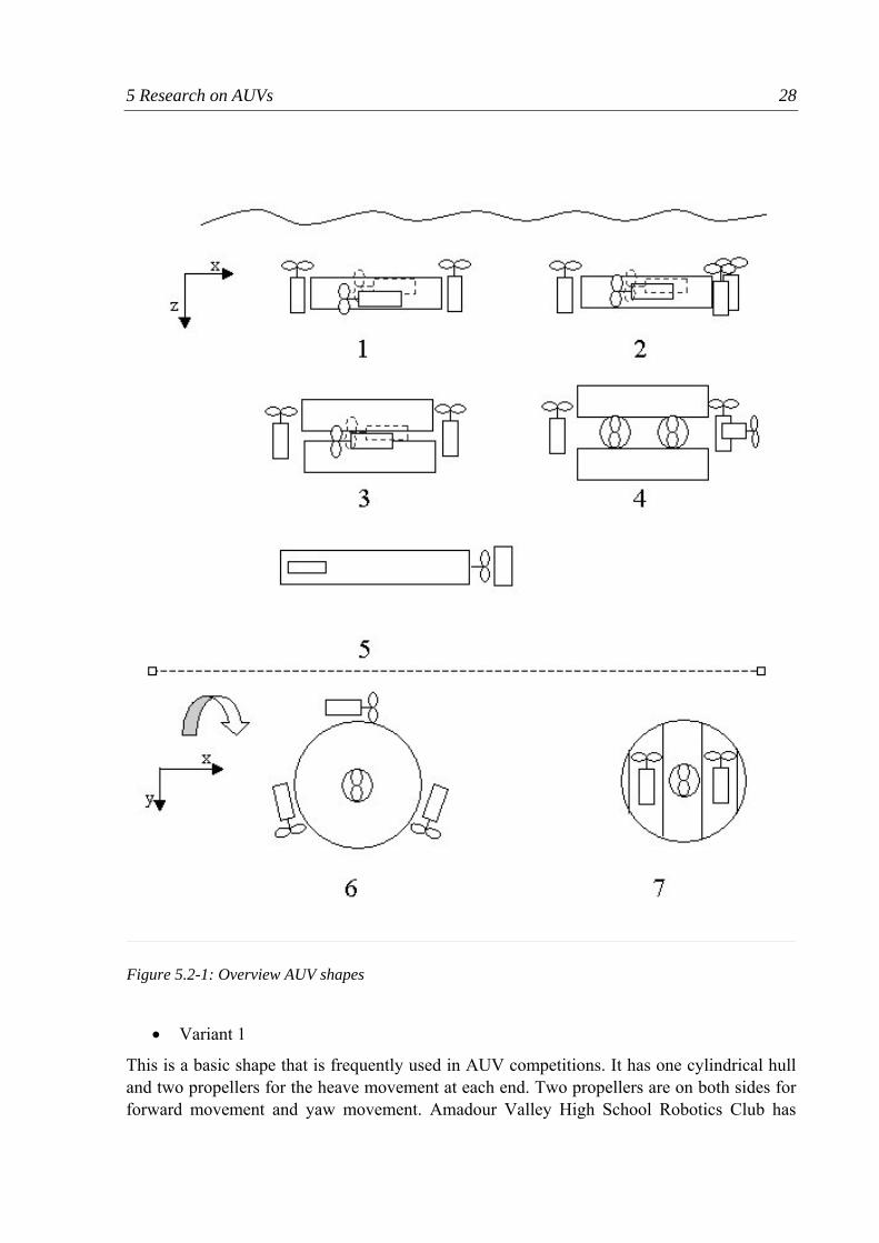
In the current case the method is not used to find new solutions, but to find a systematic way to display the different shapes of the AUVS in the 2005 competition. Out of the vast number of AUV built for university competitions in the recent year, a few representative examples for AUV-shapes are chosen and the AUV-Team which applied this design is presented (Figure 5.2-1).
5 Research on AUVs 28
• Variant 1
This is a basic shape that is frequently used in AUV competitions. It has one cylindrical hull and two propellers for the heave movement at each end. Two propellers are on both sides for forward movement and yaw movement. Amadour Valley High School Robotics Club has
Figure 5.2-1: Overview AUV shapes
5 Research on AUVs 29
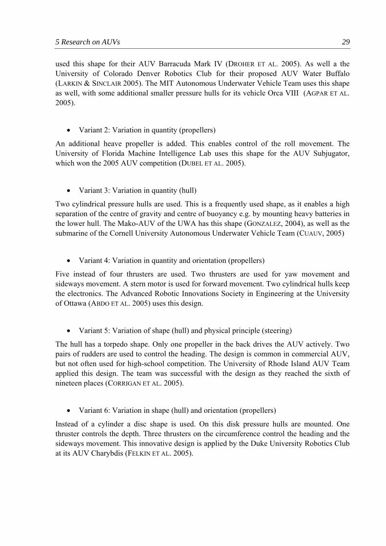
used this shape for their AUV Barracuda Mark IV (DROHER ET AL. 2005). As well a the University of Colorado Denver Robotics Club for their proposed AUV Water Buffalo (LARKIN & SINCLAIR 2005). The MIT Autonomous Underwater Vehicle Team uses this shape as well, with some additional smaller pressure hulls for its vehicle Orca VIII (AGPAR ET AL. 2005).
• Variant 2: Variation in quantity (propellers)
An additional heave propeller is added. This enables control of the roll movement. The University of Florida Machine Intelligence Lab uses this shape for the AUV Subjugator, which won the 2005 AUV competition (DUBEL ET AL. 2005).
• Variant 3: Variation in quantity (hull)
Two cylindrical pressure hulls are used. This is a frequently used shape, as it enables a high separation of the centre of gravity and centre of buoyancy e.g. by mounting heavy batteries in the lower hull. The Mako-AUV of the UWA has this shape (GONZALEZ, 2004), as well as the submarine of the Cornell University Autonomous Underwater Vehicle Team (CUAUV, 2005)
• Variant 4: Variation in quantity and orientation (propellers)
Five instead of four thrusters are used. Two thrusters are used for yaw movement and sideways movement. A stern motor is used for forward movement. Two cylindrical hulls keep the electronics. The Advanced Robotic Innovations Society in Engineering at the University of Ottawa (ABDO ET AL. 2005) uses this design.
• Variant 5: Variation of shape (hull) and physical principle (steering)
The hull has a torpedo shape. Only one propeller in the back drives the AUV actively. Two pairs of rudders are used to control the heading. The design is common in commercial AUV, but not often used for high-school competition. The University of Rhode Island AUV Team applied this design. The team was successful with the design as they reached the sixth of nineteen places (CORRIGAN ET AL. 2005).
• Variant 6: Variation in shape (hull) and orientation (propellers)
Instead of a cylinder a disc shape is used. On this disk pressure hulls are mounted. One thruster controls the depth. Three thrusters on the circumference control the heading and the sideways movement. This innovative design is applied by the Duke University Robotics Club at its AUV Charybdis (FELKIN ET AL. 2005).
5 Research on AUVs 30
• Variant 7 Variation in shape (hull) and orientation (propellers)
The pressure hull is a large sphere. Tubes that penetrate the hull hold the propellers. One propeller controls the depth and two propeller control the heading. The University of Central Florida AUV-Group applied this design on its AUV (DUBEL ET AL. 2005)
It can be seen, that a range of solutions for AUV-shapes is feasible. The single torpedo-shape (Variant 5) has a low hydrodynamic drag, and is common for commercial AUVs. It is hardly chosen in university projects as they are harder to control.
A huge amount of concepts have been realised, but one can find several similarities, that seem to be the most optimal solution for certain tasks.
• actuation by electric outboard motor-propeller combinations
• propellers instead of ballast systems or compressors for the regulation of the depth,.
• mostly bottom-heavy construction, thus no pitch and roll movement
• power supply by rechargeable batteries.
• detection of environment and collision avoidance by means of sonar
• usage of a 6-degree of freedom accelerometer for navigation
• development by teams of 3-8 students
• budget bigger than 5000€
When the list of requirements (Chapter 4.2) is taken into account the designs applied in the high school competitions can not be used in this case. The cost for building the hulls and the structures exceed the permitted maximum cost by far. Additionally the size of the described AUVs is far too big for the requirements. The aim of the project, described in this paper is to find a smaller and cheaper solution than the usual AUV-projects.
5 Research on AUVs 31
5.3 Physical properties of AUVs A short overview over the physical properties of AUVs is given.
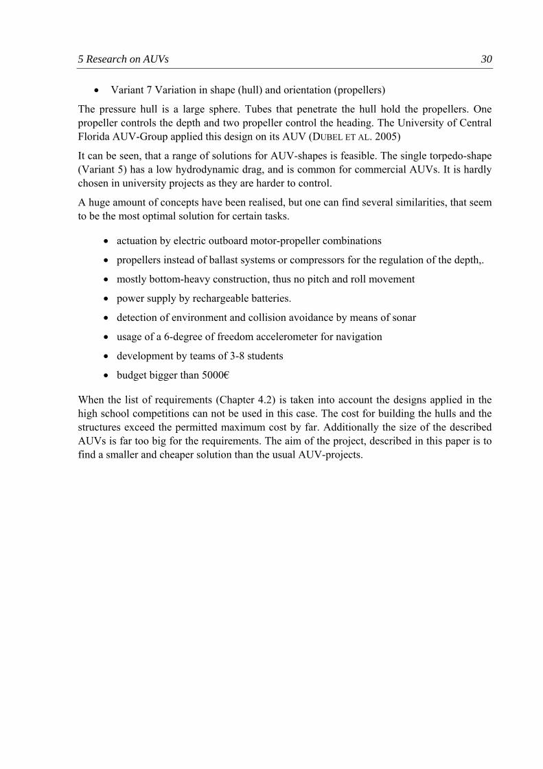
5.3.1 Coordinate system An underwater vehicle has 6 degrees of freedom (Figure 5.3-1). Three defining spatial coordinates: x, y and z. And three attitude defining angles: φ, θ and ψ. A movement along x is called surge, along y sway and along x heave. The rotational movements are called roll (θ), pitch (φ) and yaw (ψ). Due to the six degrees of freedom an AUV is quite versatile. However, normally not all degrees of freedom are controlled by actuators. It is very common to inhibit a roll and pitch movement by a bottom-heavy design.
5.3.2 Buoyancy, Stability On every submerged object a buoyancy force is acting upward. The buoyant force acts through the centroid of the displaced volume of fluid. The buoyant force is equal to the weight of the fluid displaced by the object. (STREETER ET AL. 1998, P.65)
Facing into the opposite direction, the gravity force is pushing the object downwards. The working point of the gravity force is the centre of mass of the body. The gravity force is proportional to the mass of the object. If the gravity force is bigger than the buoyancy force the object sinks. If the gravity force is smaller than the buoyancy force, it floats. If both forces are equal the object is neutral buoyant and the object remains level.
Figure 5.3-1: Degrees of freedom of an AUV
5 Research on AUVs 32
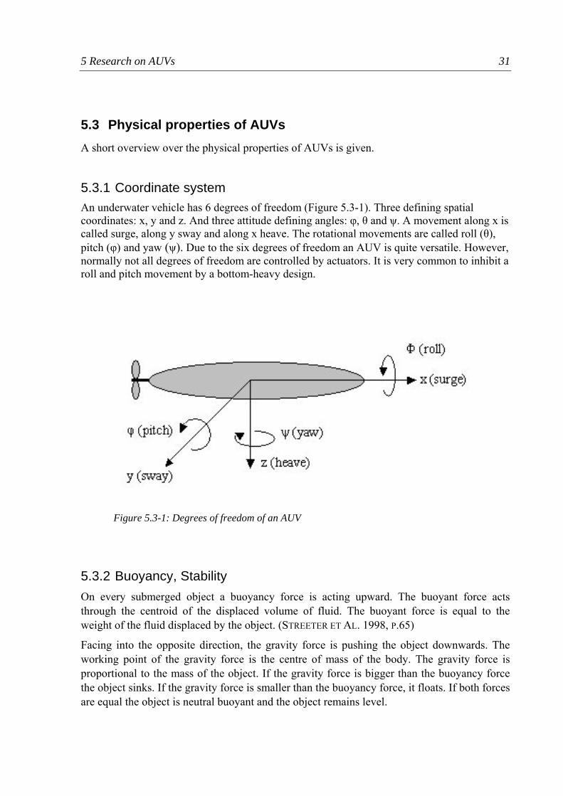
A submerged body floats in a neutral equilibrium if the two centroids coincide and the object stays stable in any given position. If the two centroids are not separated the body is rotationally stable, only when its centre of gravity is below the centre of buoyancy (Figure 5.3-2).
Ideally the two centroids are separated as much as possible to increase the stability of the body. The centre of mass can be lowered by adding weights on the lower side of the object. The result is a bottom-heavy design, that decreases roll and pitch movements.
5.3.3 Pressure A submerged AUV is exposed to a pressure, increasing linear with the depth. The equation for the pressure in no compressible fluid is:
ghpp a ρ+=
Where pa is the atmospheric pressure, ρ is the density of the fluid, g the acceleration of gravity and h is the height of the water column (MASSEY 1998, P.49).
Figure 5.3-2: Stability of a submerged body
5 Research on AUVs 33
At sea level the atmospheric pressure is 106 Pa or 1atm. This is the pressure that is carried inside the hulls when an AUV is sealed. With every 10m of depth the pressure increases by 1atm. The hulls of the AUV must be able to withstand this pressure. Also all through-hull connections like cable or shafts, which are the weakest points of AUV constructions, have to withstand this pressure. As AUV-competitions do not require depths of more than 5m the pressure on the AUV is relatively low.
The increasing pressure however enables the use of a pressure sensor for measuring the depth with a pressure sensor.
5.3.4 Drag As an AUV is moved through the water, it has to overcome drag forces opposing the movement. The drag force can be modelled with the following formula
where D is the drag force, ρ the density of the fluid, v the velocity of the object, A the reference area and Cd the drag coefficient (MASSEY 1998, P.339).
For simple geometric shapes, like disks or spheres the Cd can be found in tables. However most AUVs have a rather complex shape and drag coefficient and the reference area cannot be calculated theoretically. They can be determined by experiments or by numerical analysis tools. The following assumptions can be made. As the drag is increasing by the square of the velocity, it is better to keep the speed as low as possible. At the AUV-competitions high speeds are not desirable anyway, as additional task like object recognition are performed simultaneous. The reference area and the drag coefficient can be reduced by a streamlined shape of the AUV, by using smooth transitions and shapes that are a least bulky as possible.
dACvD 2
21 ρ=
6 Function structure 34
6 Function structure In the following chapter the development of function structures is described.
6.1 Functions structures for mechatronic systems The modelling of a function structure plays an important role in the product development process (LINDEMANN 2004, p90). By modelling the system e.g. with material, energy and signal flows the internal structure of the system can be displayed. A function is an abstract description of the relation between input and output of an object. Functions are often described in a combination of a verb and a noun. For example: “measure distance”
Motivations for setting up function models are:
• Managing the complexity of mechatronic products (see Chapter 2.3). The search for sub-solution becomes easier and the development tasks can be prioritised.
• Functions themselves only describe what has to be done, but not how. This helps to find new innovative solution across the limits of a particular discipline.
• The abstract level enables the optimisation of the product. Unnecessary functions can be eliminated; functions can be combined or interchanged.
• A function model splits a system in sub-functions. Solutions for the sub-functions can be easier found in design catalogues and collections of solutions.
• The level of detail of a function structure can be chosen to meet the purpose of the specific model. Ranging from simple black-box models, which give a good overview, to very detailed structures with sub-functions which describe every small step.
Numerous types of function models have been proposed in the realm of engineering design. A basic function model is a hierarchical function model, which gives a quick overlook of the modules of a system and their hierarchy. The main function of the system is divided into sub function, down to individual modules.
Pahl/Beitz (1996) propose a function model based on three types of flow: flow of energy, for example by a rotating shaft or a current through a wire, flow of material, e.g. gas in a pipe or a moving object and flow of signals, for example, a certain voltage as the output signal of a sensor. The flows connect the functions and build up the whole system that is circumscribed by a system boundary.
A similar function model is the flow-oriented function model (Lindemann 2004, p.98). In this model, “states” are added between the functions; hence a function changes an initial state into a terminal state. An example: electric energy (state 1) is converted (function) by an electro motor into rotational energy (state 2) of the rotating shaft.
6 Function structure 35
Rajan et al (2003) declares that most functional modelling techniques are for open loop systems with power transmission and energy conversion. For closed loop systems, as they are typical for control engineering, as well as for mechatronics, elaborate functional modelling techniques are not yet developed. He comes up with a methodology that exploits the modularity of closed loop systems. Guidelines for determining the input and output flows to subsystems are explained, as well as general functional representations that enhance the ease of deriving function structures.
Beside function models that follow the flows streaming through a system, relation oriented functional models are used to detect inconsistencies and conflicts of objectives. The functions are divided into “useful” and “harmful” functions. An example: The depth of a AUV can be measured by a pressure sensor (useful function), however to get the pressure to the sensor the hull has to be breached and is thus potential risk for a leaking exists (harmful function). Due to its neutrality the relation-oriented functional model can be applied in every discipline and is suitable for mechatronic systems. It is particularly applicable for already existing products for discovering inconsistencies. For the development of a new product the relation-oriented functional model is less efficient.
Mechatronic systems can be modelled in all the techniques described above. However it is difficult to display the software within the same model as the electric and the mechanic world. In software development different modelling techniques are used, like Nassi-Shneiderman diagram, Petri-nets or UML (Unified Modelling Language).
Mechanical and electric components are tangible, whereas software is primarily virtual. Software concepts like the object-oriented programming however enable the encapsulating of software entities called objects. The objects communicate by means of “methods”. Software objects can represent objects of the real world. For example: a propeller can be represented by a propeller-object within the software. The propeller-object has the same behaviour as the real propeller. The aim of the object-oriented programming is to get the software closer to behaviour of the real world. It should be possible to integrate those objects and their functionality into a mechatronic function model.
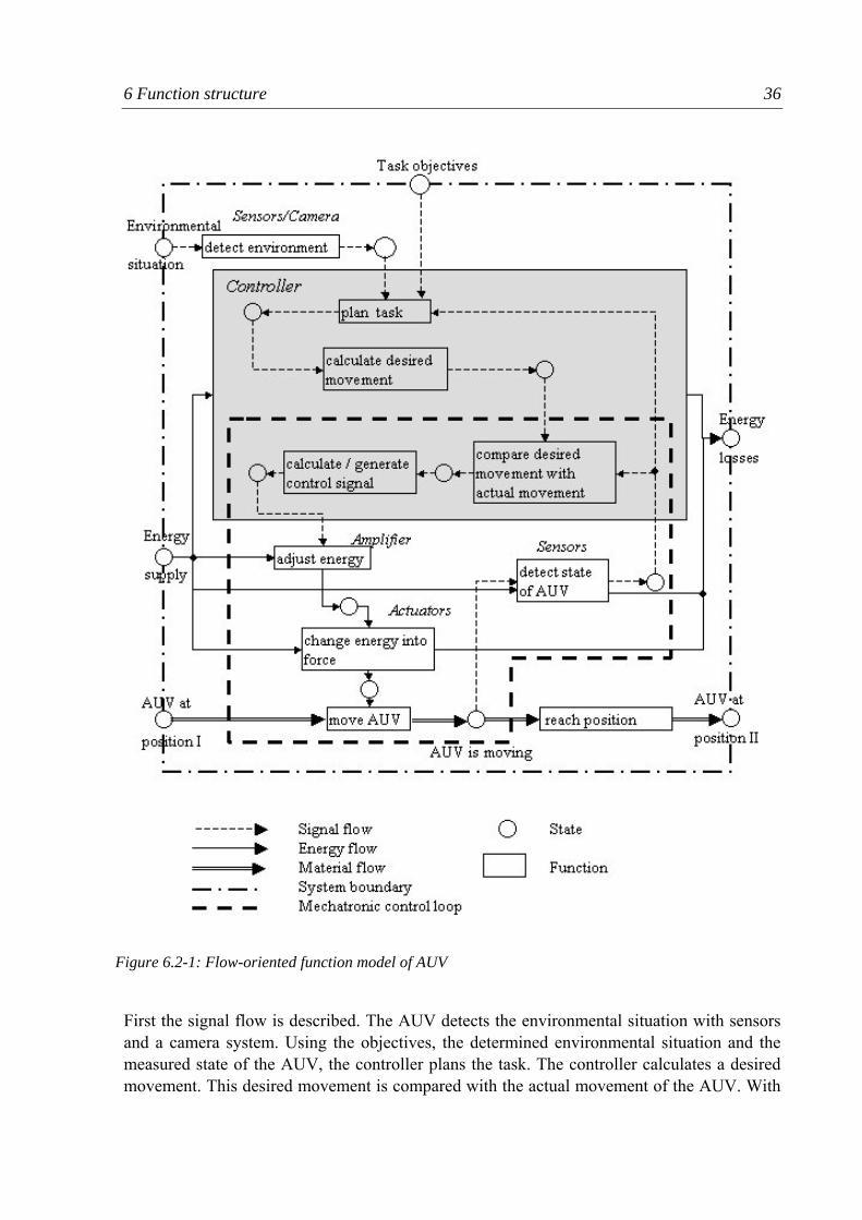
6.2 Development of function structures for the AUV As described above mechatronic systems tend to have a high numerical, relational and disciplinary complexity. As the first step a flow-oriented functional model is developed (Figure 6.2-1). The main part of the model is derived from the mechatronic control loop described in chapter 2.1, which consists of the four main elements: process, sensors, information process, actuators. The model is made of signal flows, energy flows and material flows. Typical for a mechatronic system none of these flows is dominant and a main flow respectively. The model uses functions and states. In order to increase the clarity only a few relevant states are labelled. The following states are at the system boundary in the beginning. An arbitrary starting position of the AUV in the water is assumed, the AUV possesses an energy supply. Around the AUV an environmental situation exists (pressure, distance to the wall, object on the floors, etc.) The objectives of the task are implemented in the AUV controller.
6 Function structure 36
First the signal flow is described. The AUV detects the environmental situation with sensors and a camera system. Using the objectives, the determined environmental situation and the measured state of the AUV, the controller plans the task. The controller calculates a desired movement. This desired movement is compared with the actual movement of the AUV. With
Figure 6.2-1: Flow-oriented function model of AUV
6 Function structure 37
the difference of desired and actual movement a control signal is calculated and generated. The control signal is used to adjust the energy flow going to the actuator with an amplifier. In an actuator the energy is changed into a force. In both circumstances, adjusting and changing energy, energy is lost through heat. The force generated by the actuators is used to move the AUV. This movement is detected by the sensors. The control circle according to Isermann (Chapter 2.1) is encircled in the graphic. The movement of the AUV is the material flow in the system. As the system boundary is drawn around the AUV, one could also say the AUV itself is not moving in the system, but the environment relative to the AUV.
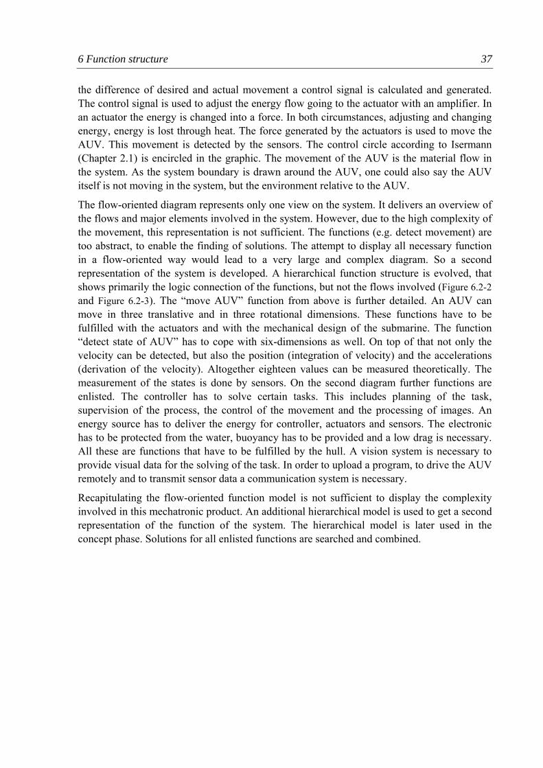
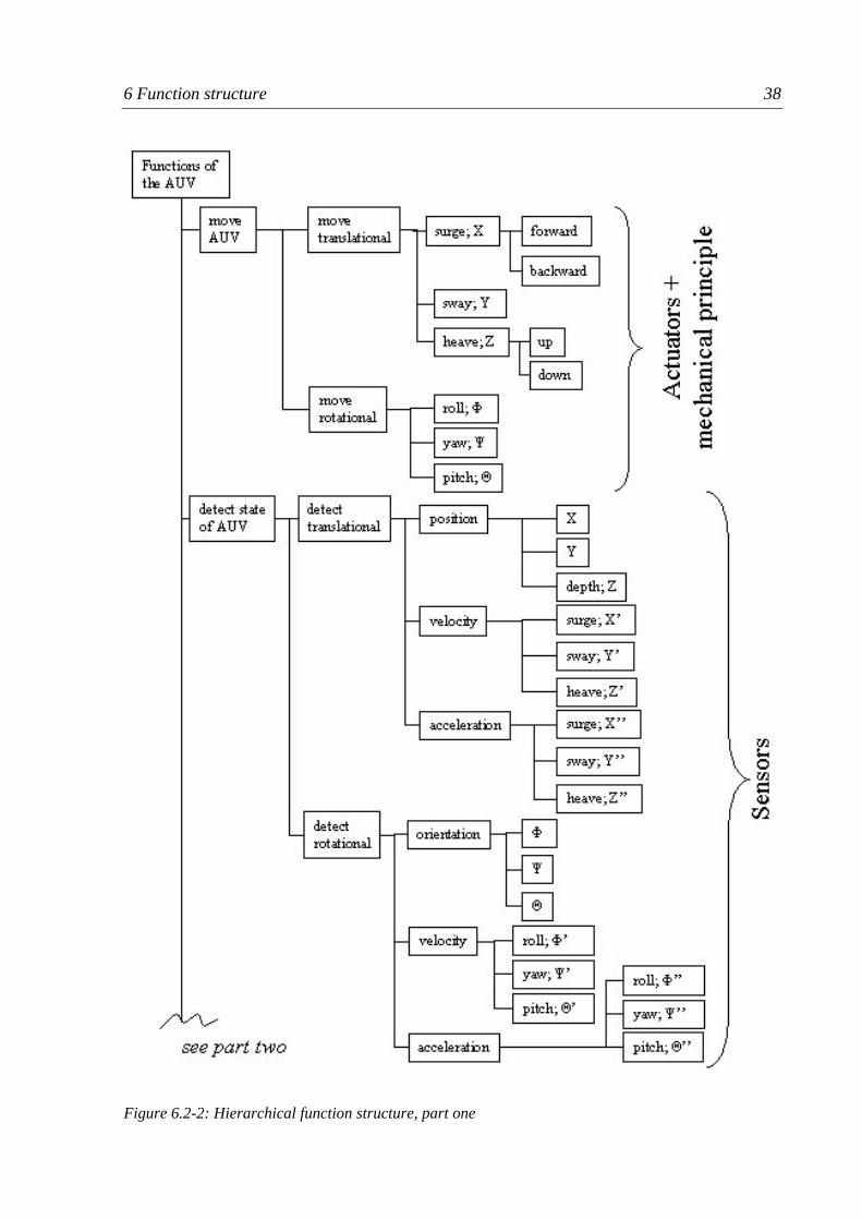
The flow-oriented diagram represents only one view on the system. It delivers an overview of the flows and major elements involved in the system. However, due to the high complexity of the movement, this representation is not sufficient. The functions (e.g. detect movement) are too abstract, to enable the finding of solutions. The attempt to display all necessary function in a flow-oriented way would lead to a very large and complex diagram. So a second representation of the system is developed. A hierarchical function structure is evolved, that shows primarily the logic connection of the functions, but not the flows involved (Figure 6.2-2 and Figure 6.2-3). The “move AUV” function from above is further detailed. An AUV can move in three translative and in three rotational dimensions. These functions have to be fulfilled with the actuators and with the mechanical design of the submarine. The function “detect state of AUV” has to cope with six-dimensions as well. On top of that not only the velocity can be detected, but also the position (integration of velocity) and the accelerations (derivation of the velocity). Altogether eighteen values can be measured theoretically. The measurement of the states is done by sensors. On the second diagram further functions are enlisted. The controller has to solve certain tasks. This includes planning of the task, supervision of the process, the control of the movement and the processing of images. An energy source has to deliver the energy for controller, actuators and sensors. The electronic has to be protected from the water, buoyancy has to be provided and a low drag is necessary. All these are functions that have to be fulfilled by the hull. A vision system is necessary to provide visual data for the solving of the task. In order to upload a program, to drive the AUV remotely and to transmit sensor data a communication system is necessary.
Recapitulating the flow-oriented function model is not sufficient to display the complexity involved in this mechatronic product. An additional hierarchical model is used to get a second representation of the function of the system. The hierarchical model is later used in the concept phase. Solutions for all enlisted functions are searched and combined.
6 Function structure 38
Figure 6.2-2: Hierarchical function structure, part one
6 Function structure 39
Figure 6.2-3: Hierarchical function structure, part two
7 Concept design 40
7 Concept design The following chapter describes the search for a concept, which includes the search for a mechanical principle, the sensors and the actuators.
7.1 General During the concept design phase an overall concept for the mechatronic has to be established. In the V-Model of the VDI-RICHTLINIE 2206 (2004, p33) this phase is called system design phase. At the development of a mechatronic system a cross-domain principle for the system has to be found. For individual sub-functions, operating principles and solution elements are sought. In order to achieve the optimum system, solutions from every discipline have to be taken into account. The connection between functions and solutions is not necessarily a 1:1 relationship. For example the housing of a AUV fulfils the functions “protect electronic”, “reduce drag” and “provide buoyancy”. It is very important, that engineers of all involved disciplines are engaged during this phase. An interdisciplinary team is a good way to get the knowledge of different departments together.
Starting point for the concept design is the function structure developed beforehand. Solutions are searched based on the functions that have to be fulfilled. Solutions can be found by various ways (LINDEMANN 2005):
• reuse of existing principles, which could be found during the research phase
• usage of design catalogues with physical effect and operating principles
• creativity methods like brainstorming, method 635 etc.
• systematic methods like TIPS (TRIZ)
• product catalogues and electronic market places
During the concept phase an interdisciplinary team has to be set up anyway, thus it is obvious that creativity methods, that have to be conducted in teams, are the most obvious approach to gain new and innovative solutions. Brainstorming is even more effective when the members have a diverse background, as so a larger field of solution can be gained and solution found in one discipline can be modified in another discipline.
The solutions found have to be structured and combined in a systematic way. The morphologic box is one method used regularly for that purpose. It enables the generation of various combinations of principles that can be compared. Out of several solutions that are found one solution has to be chosen. The solution has to fulfil the requirements that were set up during the task specification. In order to choose the best solution several assessment methods can be used, for example weighted ratings.
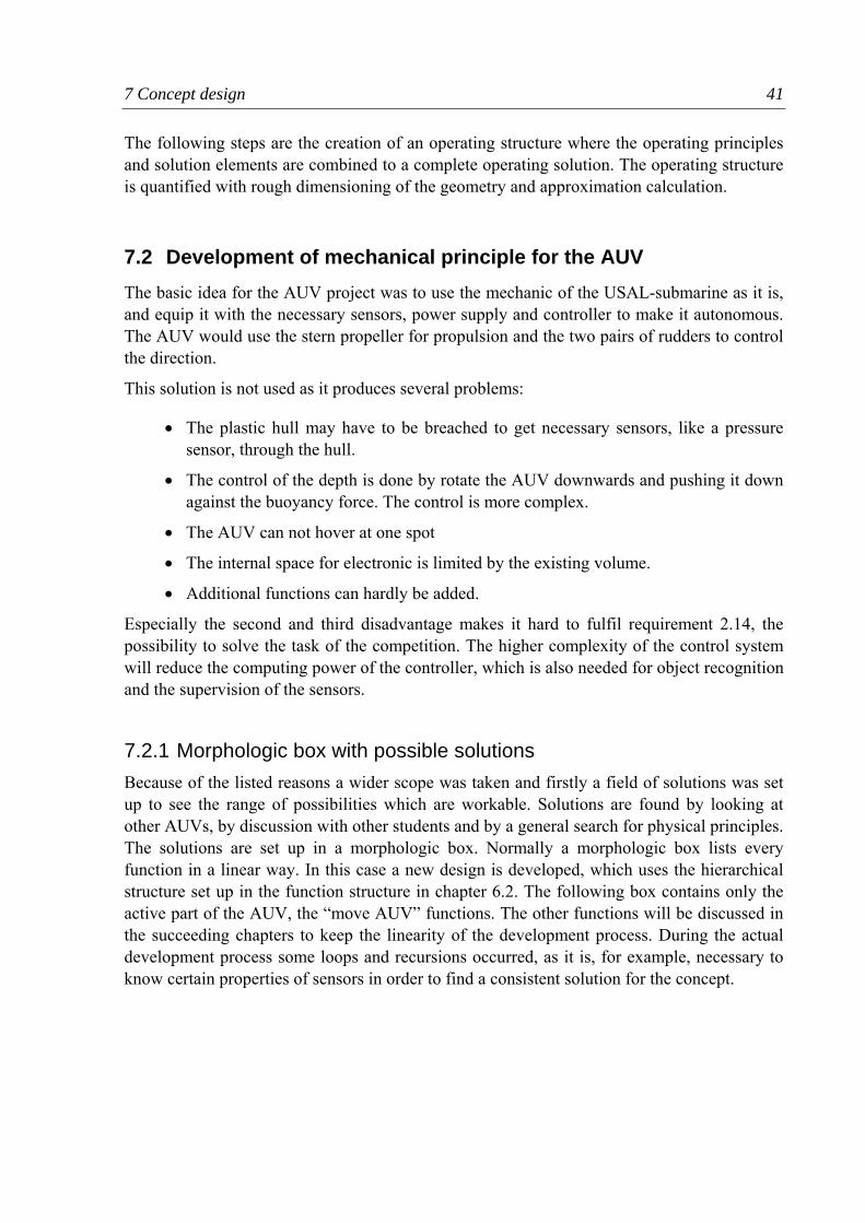
7 Concept design 41
The following steps are the creation of an operating structure where the operating principles and solution elements are combined to a complete operating solution. The operating structure is quantified with rough dimensioning of the geometry and approximation calculation.
7.2 Development of mechanical principle for the AUV The basic idea for the AUV project was to use the mechanic of the USAL-submarine as it is, and equip it with the necessary sensors, power supply and controller to make it autonomous. The AUV would use the stern propeller for propulsion and the two pairs of rudders to control the direction.
This solution is not used as it produces several problems:
• The plastic hull may have to be breached to get necessary sensors, like a pressure sensor, through the hull.
• The control of the depth is done by rotate the AUV downwards and pushing it down against the buoyancy force. The control is more complex.
• The AUV can not hover at one spot
• The internal space for electronic is limited by the existing volume.
• Additional functions can hardly be added.
Especially the second and third disadvantage makes it hard to fulfil requirement 2.14, the possibility to solve the task of the competition. The higher complexity of the control system will reduce the computing power of the controller, which is also needed for object recognition and the supervision of the sensors.
7.2.1 Morphologic box with possible solutions Because of the listed reasons a wider scope was taken and firstly a field of solutions was set up to see the range of possibilities which are workable. Solutions are found by looking at other AUVs, by discussion with other students and by a general search for physical principles. The solutions are set up in a morphologic box. Normally a morphologic box lists every function in a linear way. In this case a new design is developed, which uses the hierarchical structure set up in the function structure in chapter 6.2. The following box contains only the active part of the AUV, the “move AUV” functions. The other functions will be discussed in the succeeding chapters to keep the linearity of the development process. During the actual development process some loops and recursions occurred, as it is, for example, necessary to know certain properties of sensors in order to find a consistent solution for the concept.
7 Concept design 42
Classification Solutions
fwd 1 propeller 2 propellers fish tail x, surge
back not performed reverse propeller
propeller for backward
Y, sway not performed 1 propeller 2 propellers
not performed 1 propeller 2 propellers down
sinking trimming with snorkel
trimming with compressor
not performed 1 propeller 2 propellers
translative
movement
Z, heave
up
buoyancy trimming with snorkel
trimming with compressor
roll not performed 2 propellers rudder
pitch not performed 2 propellers rudder
rotational movement
yaw 1 propeller 2 propellers rudder
USAL-Submarine Mako-AUV
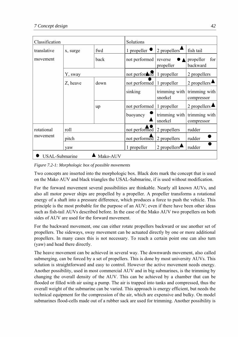
Figure 7.2-1: Morphologic box of possible movements
Two concepts are inserted into the morphologic box. Black dots mark the concept that is used on the Mako AUV and black triangles the USAL-Submarine, if is used without modification.
For the forward movement several possibilities are thinkable. Nearly all known AUVs, and also all motor power ships are propelled by a propeller. A propeller transforms a rotational energy of a shaft into a pressure difference, which produces a force to push the vehicle. This principle is the most probable for the purpose of an AUV; even if there have been other ideas such as fish-tail AUVs described before. In the case of the Mako AUV two propellers on both sides of AUV are used for the forward movement.
For the backward movement, one can either rotate propellers backward or use another set of propellers. The sideways, sway movement can be actuated directly by one or more additional propellers. In many cases this is not necessary. To reach a certain point one can also turn (yaw) and head there directly.
The heave movement can be achieved in several way. The downwards movement, also called submerging, can be forced by a set of propellers. This is done by most university AUVs. This solution is straightforward and easy to control. However the active movement needs energy. Another possibility, used in most commercial AUV and in big submarines, is the trimming by changing the overall density of the AUV. This can be achieved by a chamber that can be flooded or filled with air using a pump. The air is trapped into tanks and compressed, thus the overall weight of the submarine can be varied. This approach is energy efficient, but needs the technical equipment for the compression of the air, which are expensive and bulky. On model submarines flood-cells made out of a rubber sack are used for trimming. Another possibility is
7 Concept design 43
the usage of a snorkel that reaches out of the water surface. This snorkel can suck in air for trimming without having to compress air. A further possibility is the use of weights that push the AUV down, the weights are released when the AUV has to dive up again. This method however can be done only once the weight is released and therefore not practical for an AUV-competition. In the case of the USAL-Submarine the depth is not directly controlled. Instead, the AUV is pitching downwards with the rudders and then pushed downwards by the stern propeller. The upward movement can be done by reversing the effects described before. Most AUVs are slightly positive buoyant. So the buoyant force helps possible upward propulsion.
The rotational movements have to be considered as well. The roll movement can be actuated, for example to compensate a roll movement initialised by a stern propeller. Generally one tends to inhibit a roll movement by increasing the stability of the AUV. An active roll movement is not necessary, as with most concepts every point in the water can be reached by other movements. The pitch rotation is also inhibited in most AUVs. In the case of the USAL-submarine the rudders are used to initialise that rotation in order to tilt the submarine downwards. The yaw rotation can be actuated by propellers as done on the Mako-AUVs. Another possibility is the usage of a rudder as on the USAL-submarine. The disadvantage of rudders is that they only produce a force when the submarine is moving and thus a rotation on the spot is not possible.
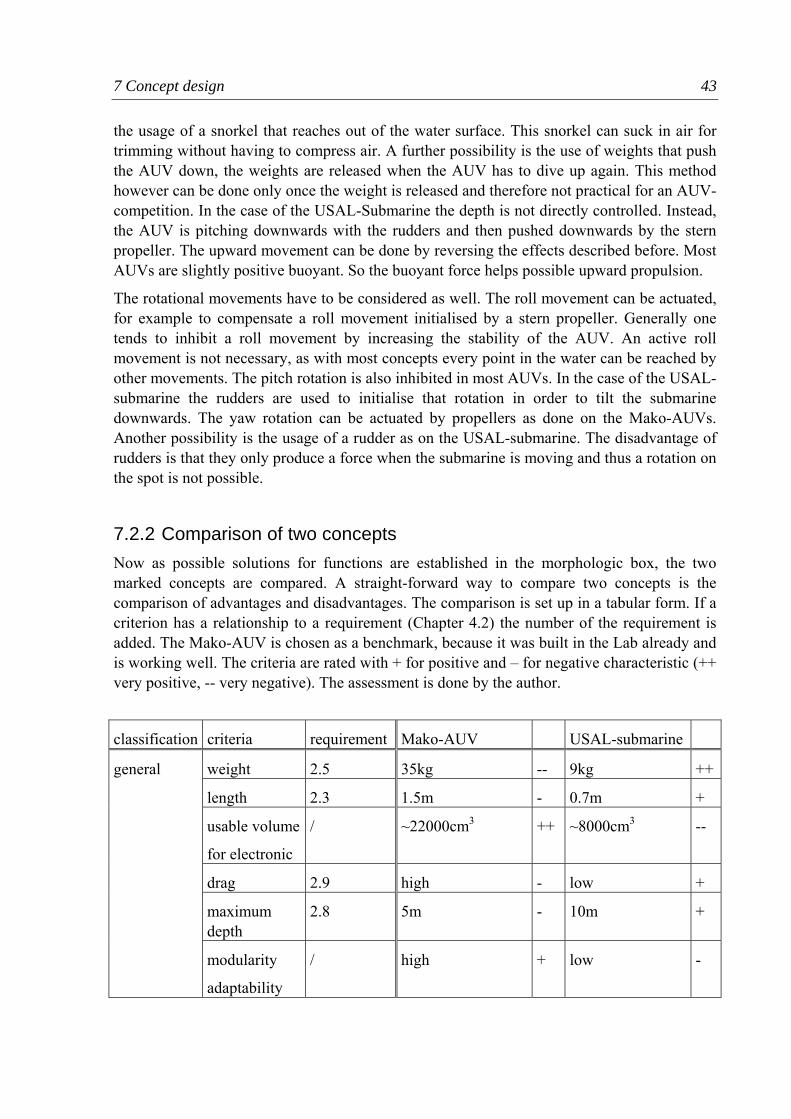
7.2.2 Comparison of two concepts Now as possible solutions for functions are established in the morphologic box, the two marked concepts are compared. A straight-forward way to compare two concepts is the comparison of advantages and disadvantages. The comparison is set up in a tabular form. If a criterion has a relationship to a requirement (Chapter 4.2) the number of the requirement is added. The Mako-AUV is chosen as a benchmark, because it was built in the Lab already and is working well. The criteria are rated with + for positive and – for negative characteristic (++ very positive, -- very negative). The assessment is done by the author.
classification criteria requirement Mako-AUV USAL-submarine
weight 2.5 35kg -- 9kg ++
length 2.3 1.5m - 0.7m +
usable volume
for electronic
/ ~22000cm3 ++ ~8000cm3 --
drag 2.9 high - low +
maximum depth
2.8 5m - 10m +
general
modularity
adaptability
/ high + low -
7 Concept design 44
possibility to hover on one spot
2.14 yes ++ no --
control of depth
2.14 simple, by propeller
+ difficult, by sway and forward movement
-
dependency of DOF
2.14 no + yes, sway and yaw rotation needs surge movement
-
movement
stability 2.14 high, separation of centre of buoyancy and gravity
+ low -
ease of modelling
/ easy, symmetrical, stable, independent DOF
+ difficult, DOF dependent
- modelling and simulation
ease of system identification
/ easy, independent experiments for each DOF
- difficult, force of rudder dependent on surge velocity and angle of rudder
+
mounting / easy, on frame - difficult, round plastic hull
+ sensors
breaching of hull
/ possible + not desired
mounting / outside, leak problem
- inside front bulb + camera
image processing
/ fast, MiniPC + slow, only space for Eyebot
-
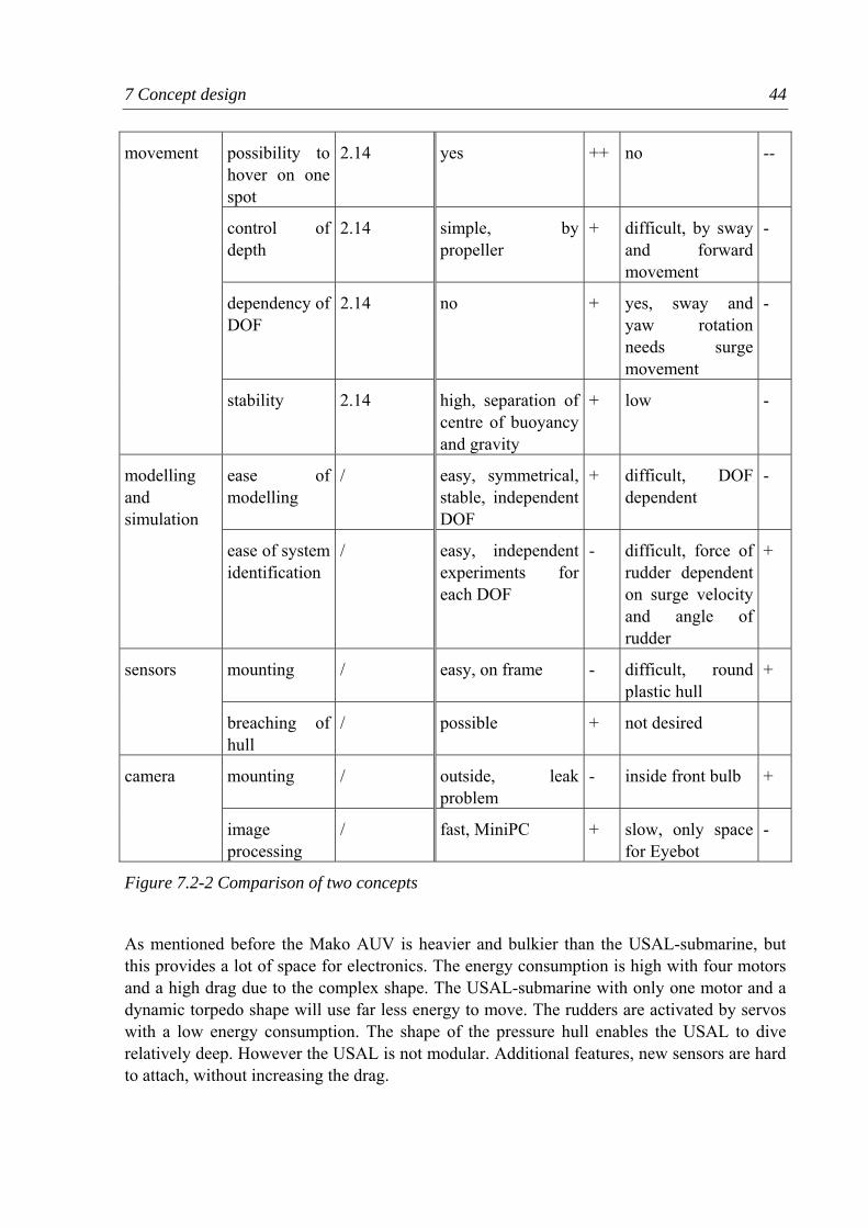
Figure 7.2-2 Comparison of two concepts
As mentioned before the Mako AUV is heavier and bulkier than the USAL-submarine, but this provides a lot of space for electronics. The energy consumption is high with four motors and a high drag due to the complex shape. The USAL-submarine with only one motor and a dynamic torpedo shape will use far less energy to move. The rudders are activated by servos with a low energy consumption. The shape of the pressure hull enables the USAL to dive relatively deep. However the USAL is not modular. Additional features, new sensors are hard to attach, without increasing the drag.
7 Concept design 45
The Mako is more versatile than the USAL. The three movements (yaw, surge, heave) can be controlled independently. The Mako can hover at a certain depth and on a spot. It can also yaw on a spot. The USAL needs a forward movement in order to get a force on the rudders. Only then a rotational movement is possible. If the speed is zero, the AUV ascends to the surface due to the buoyancy force. All these conditions make it hard to fulfil the requirement “design enables solving of the competition tasks” with the USAL AUV.
The Mako AUV is very stable as the centre of mass is lowered significantly by storing the batteries in a second, lower pressure hull. The stability of the USAL is far smaller.
For the set up of a control scheme, modelling and simulation of the AUV is desirable. The modelling for the Mako can be done relatively easy (GONZALES, 2004). It is possible to get the necessary data for system identification with independent experiments for each degree of freedom. For the USAL the modelling is more complex, as the different degrees of freedom are dependent. For example the force on the rudder is a function of the angle of the rudder, but also of the speed of the submarine. Therefore independent tests for every degree of freedom are not possible.
On the Mako AUV a camera is attached on the outside, looking downward. The camera is completely cast in resin to make it waterproof. In the USAL-submarine a camera can be put directly into the front bulb. The image processing on the Mako is done by an additional MiniPC, which is notably faster then the Eyebot controller. On the USAL-submarine there is only space for one controller.
To summarize even if the USAL-submarine fulfils most requirements listed in chapter 4.2 it has some disadvantages compared to the Mako AUV that makes it difficult for an underwater robot competition (requirement 2.14). Therefore altering the original design is feasible. However the usage of the pressure hull and the stern propellers is preferable because of the limited budget (requirement 1.1).
7.2.3 Development of new concept for AUV As the USAL has some major drawbacks a new concept is developed. The idea came from a small toy submarine. This submarine is submerged by a vertical propeller in the middle of the vehicle. Two propellers at the back are used for surge movement and for turning.
The USAL submarine consists of two parts each with about the same volume. The two parts are connected by a disk and sealed with two O-rings on each side. This disk can easily be replaced by another module with the same dimensions. The idea is to come up with a new middle part that holds thrusters for a heave movement in order to avoid the sway rotation for diving downwards. The requirements for that middle part are set-up in an additional list of requirements.
7 Concept design 46
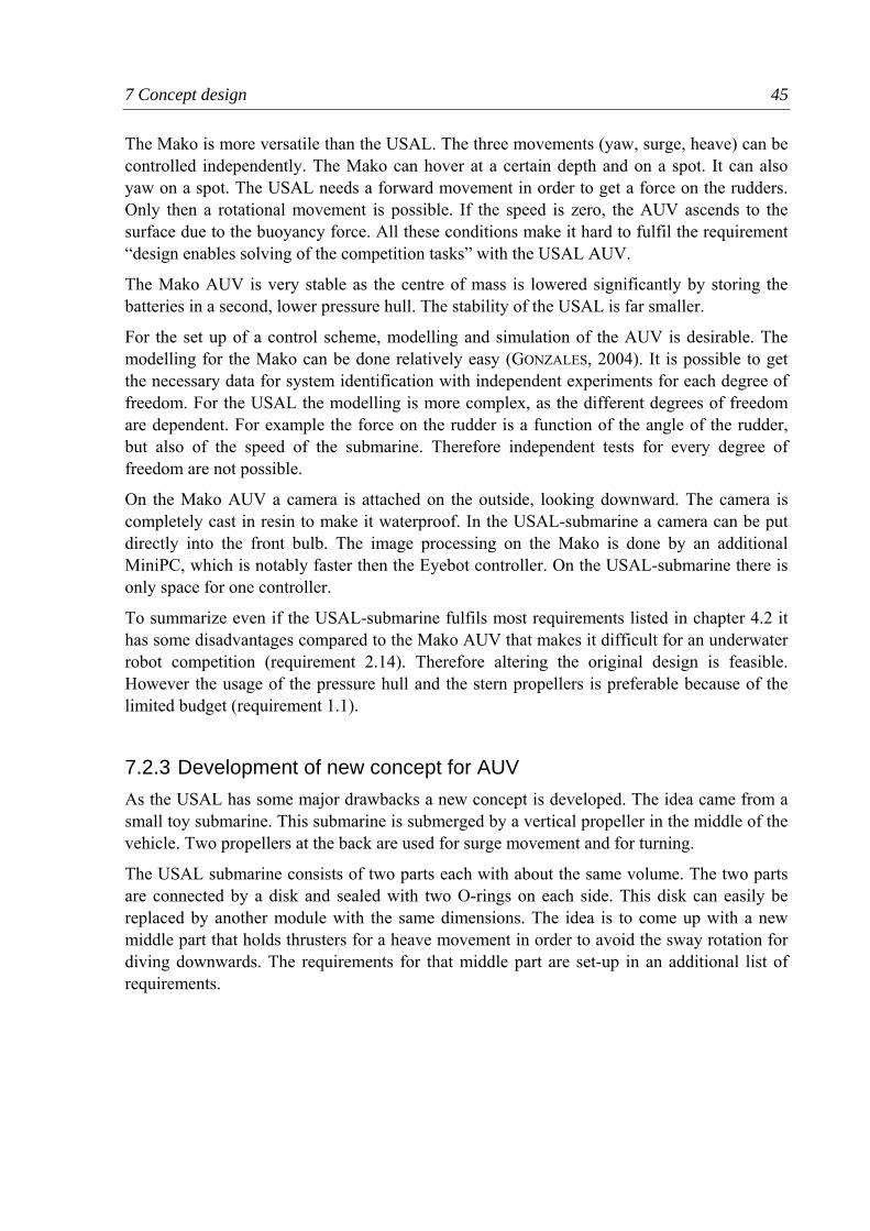
Nr. Name and description Value Unit Import Origin
min exact max
3 requirements for the middle part
1 diameter of connections 15 mm 10 diameter of hull
2 mount for heave propulsion system
10 no pitch movement wanted
3 no altering of original hull 5 reuse of USAL
4 protrusions for sensors 8 no breach of original hull
5 low centre of mass 5 higher stability
6 additional weight 2 kg 10 AUV still buoyant
Figure 7.2-3: Requirements for middle part
With the set up of these requirements the physical principle is determined. The requirements can be described in a objective sentence:
“Develop a middle part for the USAL-submarine that provides as propulsion system for a heave movement, and also enables the attachment of additional sensors, without altering the original hull.”
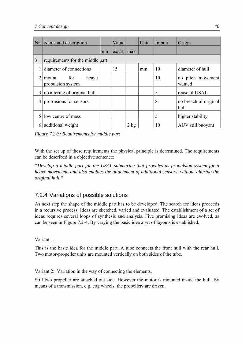
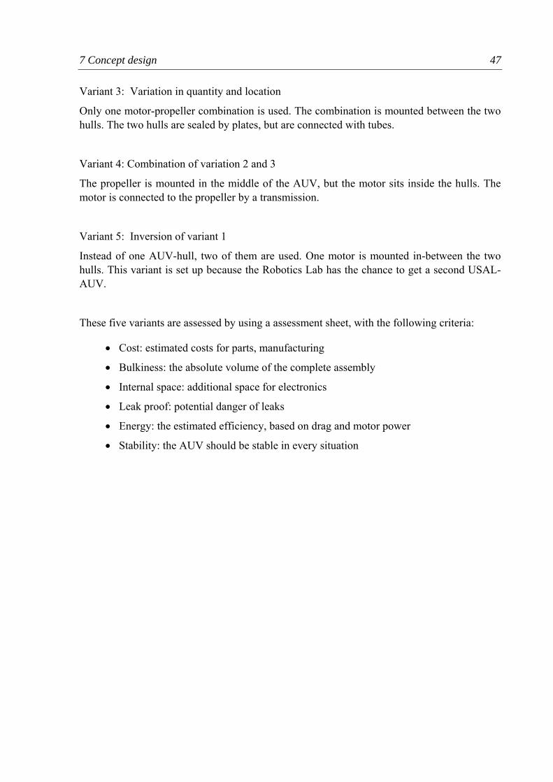
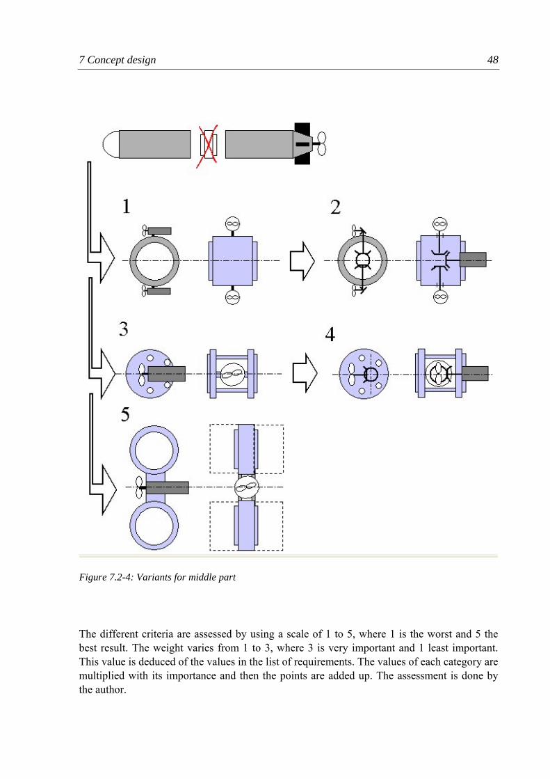
7.2.4 Variations of possible solutions As next step the shape of the middle part has to be developed. The search for ideas proceeds in a recursive process. Ideas are sketched, varied and evaluated. The establishment of a set of ideas requires several loops of synthesis and analysis. Five promising ideas are evolved, as can be seen in Figure 7.2-4. By varying the basic idea a set of layouts is established.
Variant 1:
This is the basic idea for the middle part. A tube connects the front hull with the rear hull. Two motor-propeller units are mounted vertically on both sides of the tube.
Variant 2: Variation in the way of connecting the elements.
Still two propeller are attached out side. However the motor is mounted inside the hull. By means of a transmission, e.g. cog wheels, the propellers are driven.
7 Concept design 47
Variant 3: Variation in quantity and location
Only one motor-propeller combination is used. The combination is mounted between the two hulls. The two hulls are sealed by plates, but are connected with tubes.
Variant 4: Combination of variation 2 and 3
The propeller is mounted in the middle of the AUV, but the motor sits inside the hulls. The motor is connected to the propeller by a transmission.
Variant 5: Inversion of variant 1
Instead of one AUV-hull, two of them are used. One motor is mounted in-between the two hulls. This variant is set up because the Robotics Lab has the chance to get a second USAL-AUV.
These five variants are assessed by using a assessment sheet, with the following criteria:
• Cost: estimated costs for parts, manufacturing
• Bulkiness: the absolute volume of the complete assembly
• Internal space: additional space for electronics
• Leak proof: potential danger of leaks
• Energy: the estimated efficiency, based on drag and motor power
• Stability: the AUV should be stable in every situation
7 Concept design 48
The different criteria are assessed by using a scale of 1 to 5, where 1 is the worst and 5 the best result. The weight varies from 1 to 3, where 3 is very important and 1 least important. This value is deduced of the values in the list of requirements. The values of each category are multiplied with its importance and then the points are added up. The assessment is done by the author.
Figure 7.2-4: Variants for middle part

7 Concept design 49
Weight Variant 1 Variant 2 Variant 3 Variant 4 Variant 5
Cost 3 2 1 5 2 4
Bulkiness 3 3 3 5 5 1
Internal space
1 4 3 2 1 5
Leak proof 2 5 2 4 2 5
Energy 2 1 1 4 5 3
Stability 1 4 4 2 2 5
Sum 35 25 50 38 41
Figure 7.2-5: Weighted rating of variants
Variant 3 gets the most points and is the one that will be detailed in the following. The advantage of variant 3 is it low cost, as it needs only one motor and no transmission. As no rotating axle is intersecting the hull, the proper sealing is easier. The AUV does not get very bulky; it does not get broader, but a bit longer. The stability is doubtful, as only one motor can not compensate a roll movement. By lowering the centre of mass, this problem should become negligible. An additional problem might be, that the rotating motor is turning the whole AUV as a reaction movement. This can be kept small by having a very low buoyancy, so that the motor does not have to rotate fast. The yaw reaction movement can be compensated with the rudders when moving forward.
With variant 3 two sealed compartments are produced. The front part will host the battery and the Eyebot controller plus additional sensors. In the back of the AUV, the motor controller, the motor for the stern propeller as well as the servo for the rudders will take place.
In the following chapters the selection of sensors and actuators is described. During the development process several loops are taken, to find a solution that fulfils the space requirements.
7.3 Actuators The usage of actuators in mechatronics system is explained, as well as the actuators used in the AUV-project
7.3.1 General Technical processes are influenced by the actuators, which affect certain input variables (ISERMANN, 2003, p.383). Actuators transform low-power manipulated variables (e.g. in the case of the Eyebot controller: 5V pulse-width modulated signals) into process input variable of much higher power lever. The power needed for actuating is provided by an auxiliary
7 Concept design 50
energy supply, which is fed by a power amplifier. The auxiliary energy supply can be electrical, pneumatic or hydraulic. Actuators can provide translative or rotational movement, a force or a torque.
Some actuators are feedback controlled, in order to eliminate disturbance by properties like friction, backlash, electromagnetic hysteresis. This requires an additional sensor integrated in the actuator, which measures displacements, velocities or forces.
7.3.2 Actuators for the AUV Three actuators are necessary for the proposed design of the AUV. Two motors provide a rotational movement and a servo for the rudder.
7.3.2.1 Servo motor for rudder
Only the vertical set of rudders of the USAL submarine is used. The horizontal rudders are removed as a pitch movement is not wanted and the rudders would disturb the downward movement of the AUV propelled by the heave motor.
The rudder is actuated by a standard 5V servo motor which can be positioned to a certain angle. The motor has a feedback control and is activated by a pulse-width modulated signal. The two rudders are connected to the servo motor through a set of leverages. The rudders are connected to shafts that penetrate the hull. The shafts are pivoted and sealed by two O-rings. The O-rings induce a high friction that has to be overpowered by the servo motor. The high friction together with some play and elasticity in the leverages lead to a hysteresis. The input signal and the actual angle of the rudder are dependent on the direction of the movement.
The original servo motor is too weak to move the rudders properly. A high torque servo motor (Hitec Ultra Torque HS/945MG) with metal gearbox is purchased, which works more satisfactorily. The hysteresis is compensated by the program which sets different input values depending on the direction of the rotation. The construction of the leverage enables a maximum rotation of the rudders by +/-30 degrees.
7.3.2.2 Electro motor for stern propeller
The stern propeller is driven by the original 12V electro motor. The propeller is coupled with the motor by a magnetic transmission, so that no rotation shaft is penetrating the hull. This solution improves the water tightness of the AUV. The motor is driven by an amplifier board. Two signals are used one for the speed and one for the direction.
7.3.2.3 Electro motor for heave propeller
For the heave movement a Sevylor 12 V outboard trolling motor is purchased. The motor is delivered with a propeller and has a sealed shaft, which makes it practical for underwater usage. The major back draw of the motor is the high current draw. Unlike the description of the specification with 1.8A, the motor does not start spinning below a current of 3A. The maximum current draw is 5.8A.
7 Concept design 51
The motor is driven by an MOSFET H-bridge power amplifier. Two signal pulse-width signals are used: one to determine the direction of the motor, the other one for the speed. Due to the high currents the MOSFET get hot and have to be cooled with a heat-sink. The rear aluminium plate of the middle section is used for that purpose.
The motor is the same as the one used on the MAKO-AUV. Tests performed with them show that the maximum force produced by the propeller is 22N, which is equal 2,2kg of weight. The positive buoyancy of the AUV must be smaller than this, otherwise the propeller is not able to push it down.
7.4 Sensors In this chapter the use of sensors is described in general, as well as the search for sensors for the AUV.
7.4.1 General Sensors provide the required measurable information about the process in a mechatronic system (ISERMANN 2003, p360). They represent the link between the process and the information-processing part. Sensors measure mechanical, electrical or thermal quantities, by a physical effect and transform it into an electrical signal.
The transformation with a physical effect is divided into main and side effects. The main effect is used to generate the desired signal. A side effect disturbs the main effect due to additional interference. For instance, a resistance of a strain gage is dependent on the extension of the gage (main effect), but may also alter due to the influence of temperature changes (side effect).
Several criteria can be used to evaluate a sensor. The sensitivity of a sensor describes the ratio of the change of the output signal to the measures value. Linearity, hysteresis and repeatability are further important properties.
The electrical signal of the sensor can be classified in:
• amplitude-modulated signals
• frequency-modulated signals
• digital signals
Amplitude-modulated signals are proportional to the measured quantity. Amplitude-modulated signals have to be converted into a digital signal in order to interface them with a digital controller. At a frequency-modulated signal, the frequency is proportional to the measured quantity. The signal can be read by a controller with a frequency counter. A digital signal is an encoded signal of the measured quantity, either as serial or as parallel signal. These signals can be read directly by a digital controller.
Several sensor principles are used in general. A brief overview follows.
7 Concept design 52
Displacement measurement is used to measure a distance, an absolute or relative displacement or an angular rotation. The sensors reach from high-precision sensors for measurements in µ-ranges (e.g. inductive sensors) to sensors measuring distances in meter ranges (e.g. distance measurement with laser triangulation). Further examples of displacement sensors are: restrictive sensors, capacitive sensors, code sensors, incremental sensors and hall sensors. Another possibility is the integration of the signal of a velocity sensor. However as any errors of the measurement are accumulated, a drift between actual and calculated position occurs.
For measuring velocity it is possible to differentiate the signal of displacement or angular sensors. This however, amplifies the noise relative to the signal. Velocity can be measured with active electro-dynamic sensors that work like generators or with inductive effects. Sensors that work as incremental sensors are very common. An incremental wheel either induces a voltage in a coil with a magnet, or an optical sensor is interrupted with a slotted wheel. The signal of incremental sensors is a pulse sequence, with the frequency corresponding to the speed of the wheel.
Accelerations can be calculated by differentiating a velocity signal. As mentioned before, the differentiating amplifies the noise and makes low-pass filtering inevitable. Accelerometers are based on the relationship between the acceleration of a mass m and the inertial force F : a=F/m. In an accelerometer a mass is suspended by a spring system and the displacement is measured by displacement sensors.
Furthermore sensors are used for force and pressure measurement. The measurement is performed indirectly by measuring the displacement of a spring or a diaphragm with a displacement sensor.
7.4.2 Sensors for the AUV In the chapter functional modelling (chapter 6.2) the possible measurable movements are listed. A morphologic box is used to set-up the possible solutions (Figure 8.2-1).
First of all the position of the AUV has to be determined. In an open-water environment the interest is primarily on the global position, which is then compared with a map. In this case the AUV is acting in a pool with straight walls, so the AUV has to know the relative position to the wall. This helps to prevent collisions with the wall, and enables tasks like wall-following and the driving of search patterns. The position can be integrated by using the heading and the measured speed. This method is called dead-reckoning and is used whenever an absolute position measurement is not possible. (WIKIPEDIA, 2005b).
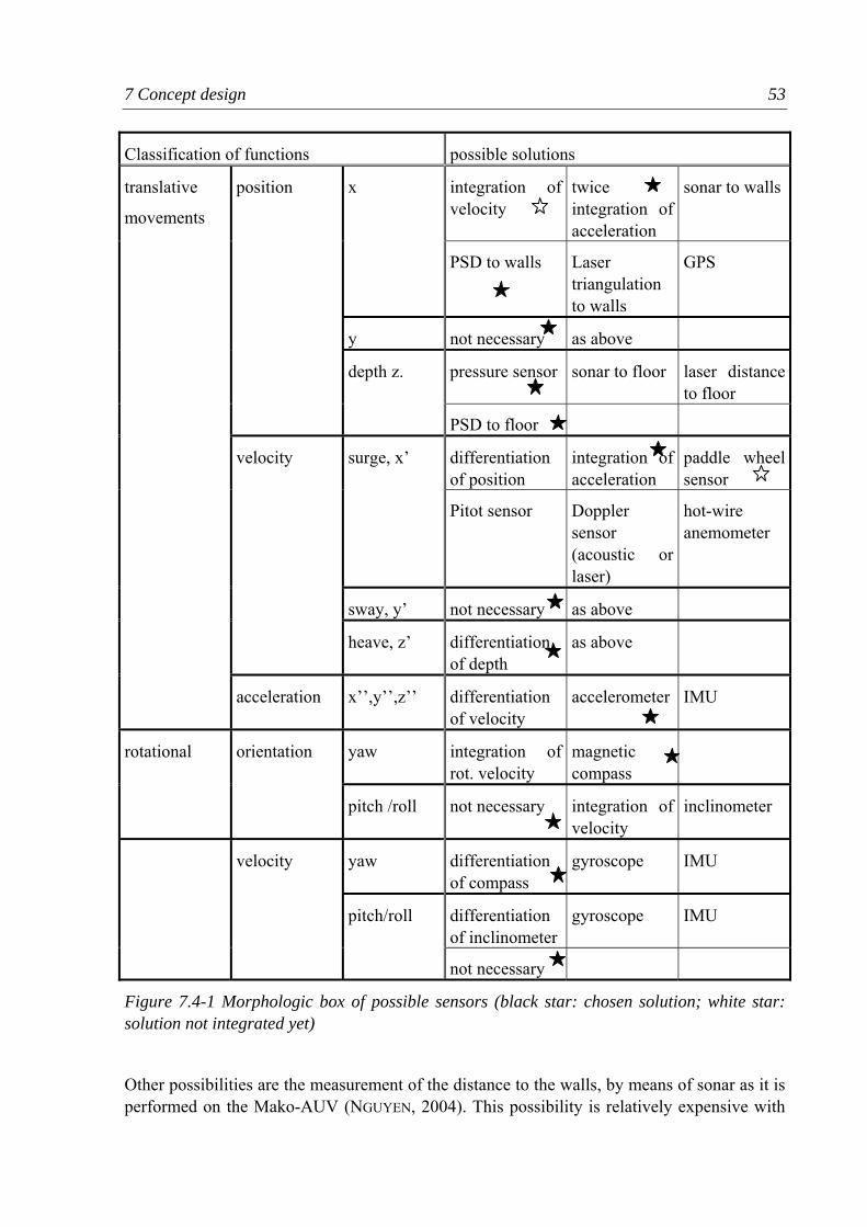
7 Concept design 53
Classification of functions possible solutions
integration of velocity
twice integration of acceleration
sonar to wallsx
PSD to walls Laser triangulation to walls
GPS
y not necessary as above
pressure sensor sonar to floor laser distance to floor
position
depth z.
PSD to floor
differentiation of position
integration of acceleration
paddle wheel sensor
surge, x’
Pitot sensor Doppler sensor (acoustic or laser)
hot-wire anemometer
sway, y’ not necessary as above
velocity
heave, z’ differentiation of depth
as above
translative
movements
acceleration x’’,y’’,z’’ differentiation of velocity
accelerometer IMU
yaw integration of rot. velocity
magnetic compass
rotational orientation
pitch /roll not necessary integration of velocity
inclinometer
yaw differentiation of compass
gyroscope IMU
differentiation of inclinometer
gyroscope IMU
velocity
pitch/roll
not necessary
Figure 7.4-1 Morphologic box of possible sensors (black star: chosen solution; white star: solution not integrated yet)
Other possibilities are the measurement of the distance to the walls, by means of sonar as it is performed on the Mako-AUV (NGUYEN, 2004). This possibility is relatively expensive with
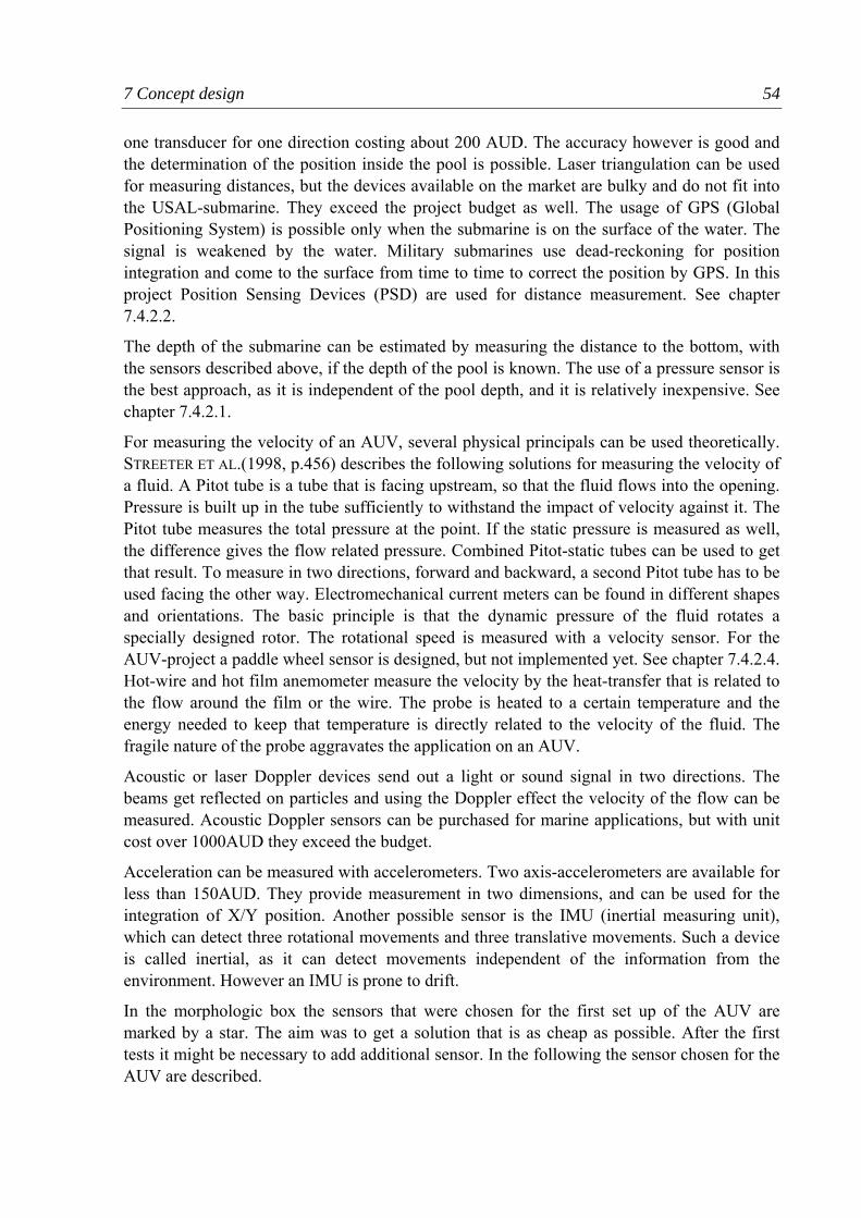
7 Concept design 54
one transducer for one direction costing about 200 AUD. The accuracy however is good and the determination of the position inside the pool is possible. Laser triangulation can be used for measuring distances, but the devices available on the market are bulky and do not fit into the USAL-submarine. They exceed the project budget as well. The usage of GPS (Global Positioning System) is possible only when the submarine is on the surface of the water. The signal is weakened by the water. Military submarines use dead-reckoning for position integration and come to the surface from time to time to correct the position by GPS. In this project Position Sensing Devices (PSD) are used for distance measurement. See chapter 7.4.2.2.
The depth of the submarine can be estimated by measuring the distance to the bottom, with the sensors described above, if the depth of the pool is known. The use of a pressure sensor is the best approach, as it is independent of the pool depth, and it is relatively inexpensive. See chapter 7.4.2.1.
For measuring the velocity of an AUV, several physical principals can be used theoretically. STREETER ET AL.(1998, p.456) describes the following solutions for measuring the velocity of a fluid. A Pitot tube is a tube that is facing upstream, so that the fluid flows into the opening. Pressure is built up in the tube sufficiently to withstand the impact of velocity against it. The Pitot tube measures the total pressure at the point. If the static pressure is measured as well, the difference gives the flow related pressure. Combined Pitot-static tubes can be used to get that result. To measure in two directions, forward and backward, a second Pitot tube has to be used facing the other way. Electromechanical current meters can be found in different shapes and orientations. The basic principle is that the dynamic pressure of the fluid rotates a specially designed rotor. The rotational speed is measured with a velocity sensor. For the AUV-project a paddle wheel sensor is designed, but not implemented yet. See chapter 7.4.2.4. Hot-wire and hot film anemometer measure the velocity by the heat-transfer that is related to the flow around the film or the wire. The probe is heated to a certain temperature and the energy needed to keep that temperature is directly related to the velocity of the fluid. The fragile nature of the probe aggravates the application on an AUV.
Acoustic or laser Doppler devices send out a light or sound signal in two directions. The beams get reflected on particles and using the Doppler effect the velocity of the flow can be measured. Acoustic Doppler sensors can be purchased for marine applications, but with unit cost over 1000AUD they exceed the budget.
Acceleration can be measured with accelerometers. Two axis-accelerometers are available for less than 150AUD. They provide measurement in two dimensions, and can be used for the integration of X/Y position. Another possible sensor is the IMU (inertial measuring unit), which can detect three rotational movements and three translative movements. Such a device is called inertial, as it can detect movements independent of the information from the environment. However an IMU is prone to drift.
In the morphologic box the sensors that were chosen for the first set up of the AUV are marked by a star. The aim was to get a solution that is as cheap as possible. After the first tests it might be necessary to add additional sensor. In the following the sensor chosen for the AUV are described.
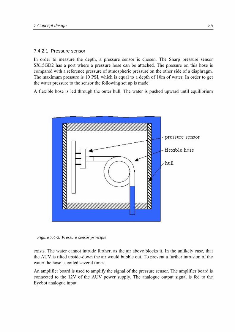
7 Concept design 55
7.4.2.1 Pressure sensor
In order to measure the depth, a pressure sensor is chosen. The Sharp pressure sensor SX15GD2 has a port where a pressure hose can be attached. The pressure on this hose is compared with a reference pressure of atmospheric pressure on the other side of a diaphragm. The maximum pressure is 10 PSI, which is equal to a depth of 10m of water. In order to get the water pressure to the sensor the following set up is made
A flexible hose is led through the outer hull. The water is pushed upward until equilibrium
exists. The water cannot intrude further, as the air above blocks it. In the unlikely case, that the AUV is tilted upside-down the air would bubble out. To prevent a further intrusion of the water the hose is coiled several times.
An amplifier board is used to amplify the signal of the pressure sensor. The amplifier board is connected to the 12V of the AUV power supply. The analogue output signal is fed to the Eyebot analogue input.
Figure 7.4-2: Pressure sensor principle
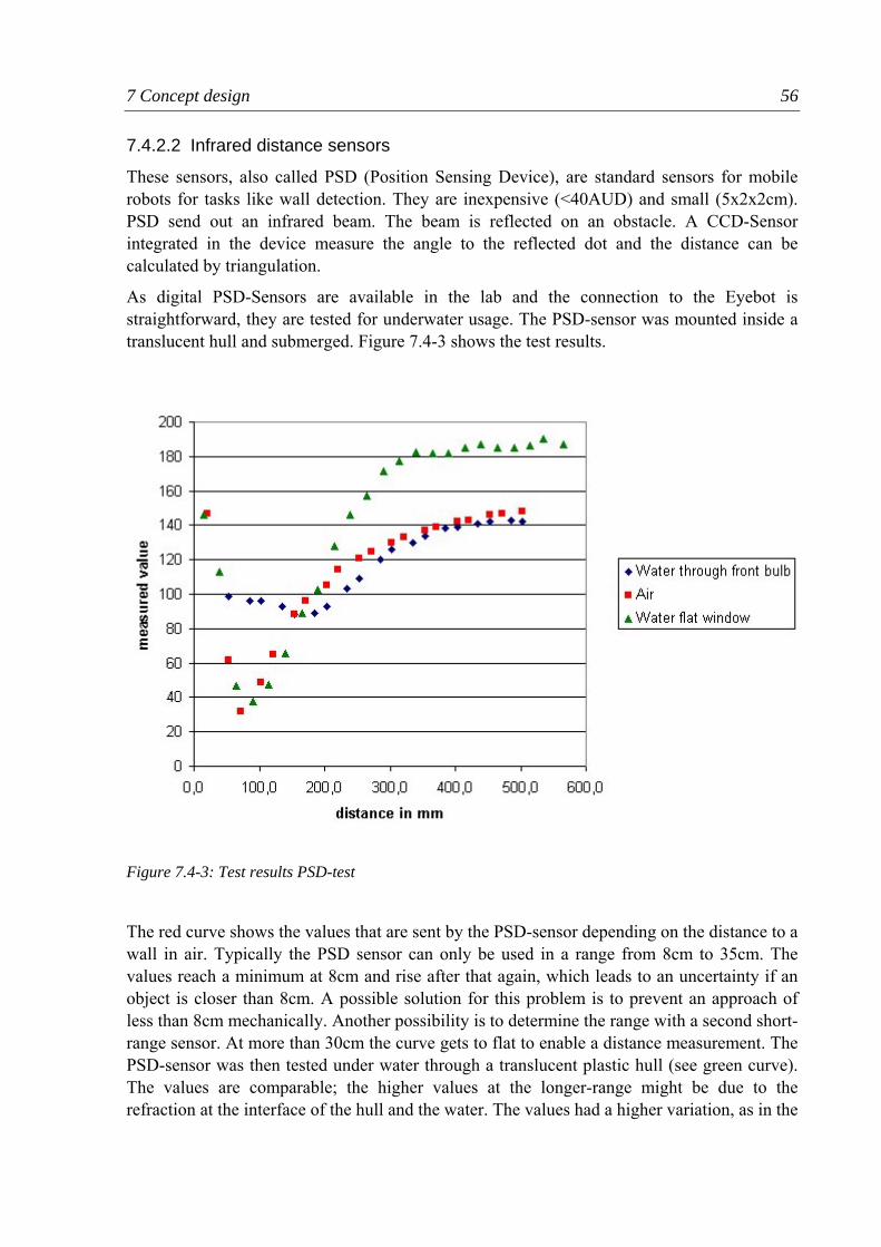
7 Concept design 56
7.4.2.2 Infrared distance sensors
These sensors, also called PSD (Position Sensing Device), are standard sensors for mobile robots for tasks like wall detection. They are inexpensive (<40AUD) and small (5x2x2cm). PSD send out an infrared beam. The beam is reflected on an obstacle. A CCD-Sensor integrated in the device measure the angle to the reflected dot and the distance can be calculated by triangulation.
As digital PSD-Sensors are available in the lab and the connection to the Eyebot is straightforward, they are tested for underwater usage. The PSD-sensor was mounted inside a translucent hull and submerged. Figure 7.4-3 shows the test results.
The red curve shows the values that are sent by the PSD-sensor depending on the distance to a wall in air. Typically the PSD sensor can only be used in a range from 8cm to 35cm. The values reach a minimum at 8cm and rise after that again, which leads to an uncertainty if an object is closer than 8cm. A possible solution for this problem is to prevent an approach of less than 8cm mechanically. Another possibility is to determine the range with a second short-range sensor. At more than 30cm the curve gets to flat to enable a distance measurement. The PSD-sensor was then tested under water through a translucent plastic hull (see green curve). The values are comparable; the higher values at the longer-range might be due to the refraction at the interface of the hull and the water. The values had a higher variation, as in the
Figure 7.4-3: Test results PSD-test
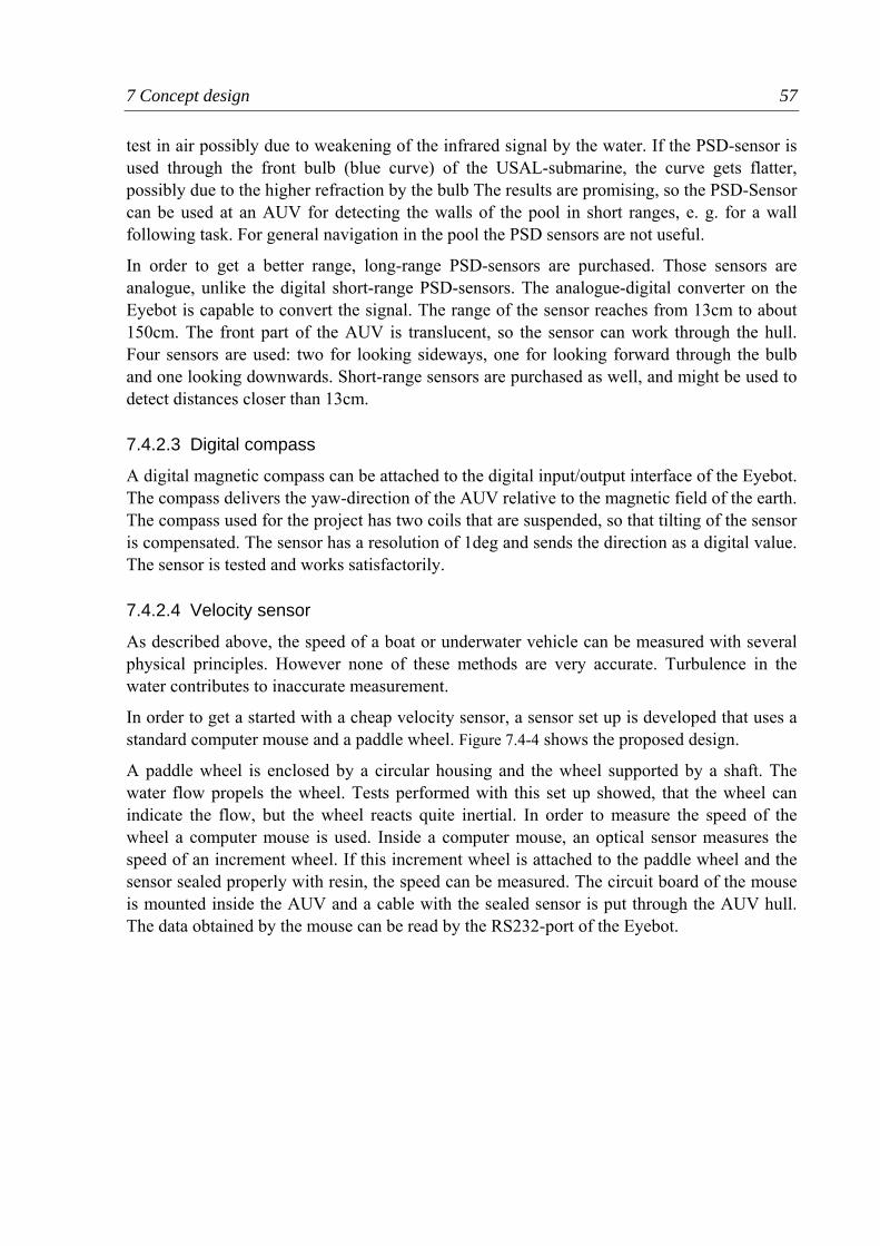
7 Concept design 57
test in air possibly due to weakening of the infrared signal by the water. If the PSD-sensor is used through the front bulb (blue curve) of the USAL-submarine, the curve gets flatter, possibly due to the higher refraction by the bulb The results are promising, so the PSD-Sensor can be used at an AUV for detecting the walls of the pool in short ranges, e. g. for a wall following task. For general navigation in the pool the PSD sensors are not useful.
In order to get a better range, long-range PSD-sensors are purchased. Those sensors are analogue, unlike the digital short-range PSD-sensors. The analogue-digital converter on the Eyebot is capable to convert the signal. The range of the sensor reaches from 13cm to about 150cm. The front part of the AUV is translucent, so the sensor can work through the hull. Four sensors are used: two for looking sideways, one for looking forward through the bulb and one looking downwards. Short-range sensors are purchased as well, and might be used to detect distances closer than 13cm.
7.4.2.3 Digital compass
A digital magnetic compass can be attached to the digital input/output interface of the Eyebot. The compass delivers the yaw-direction of the AUV relative to the magnetic field of the earth. The compass used for the project has two coils that are suspended, so that tilting of the sensor is compensated. The sensor has a resolution of 1deg and sends the direction as a digital value. The sensor is tested and works satisfactorily.
7.4.2.4 Velocity sensor
As described above, the speed of a boat or underwater vehicle can be measured with several physical principles. However none of these methods are very accurate. Turbulence in the water contributes to inaccurate measurement.
In order to get a started with a cheap velocity sensor, a sensor set up is developed that uses a standard computer mouse and a paddle wheel. Figure 7.4-4 shows the proposed design.
A paddle wheel is enclosed by a circular housing and the wheel supported by a shaft. The water flow propels the wheel. Tests performed with this set up showed, that the wheel can indicate the flow, but the wheel reacts quite inertial. In order to measure the speed of the wheel a computer mouse is used. Inside a computer mouse, an optical sensor measures the speed of an increment wheel. If this increment wheel is attached to the paddle wheel and the sensor sealed properly with resin, the speed can be measured. The circuit board of the mouse is mounted inside the AUV and a cable with the sealed sensor is put through the AUV hull. The data obtained by the mouse can be read by the RS232-port of the Eyebot.
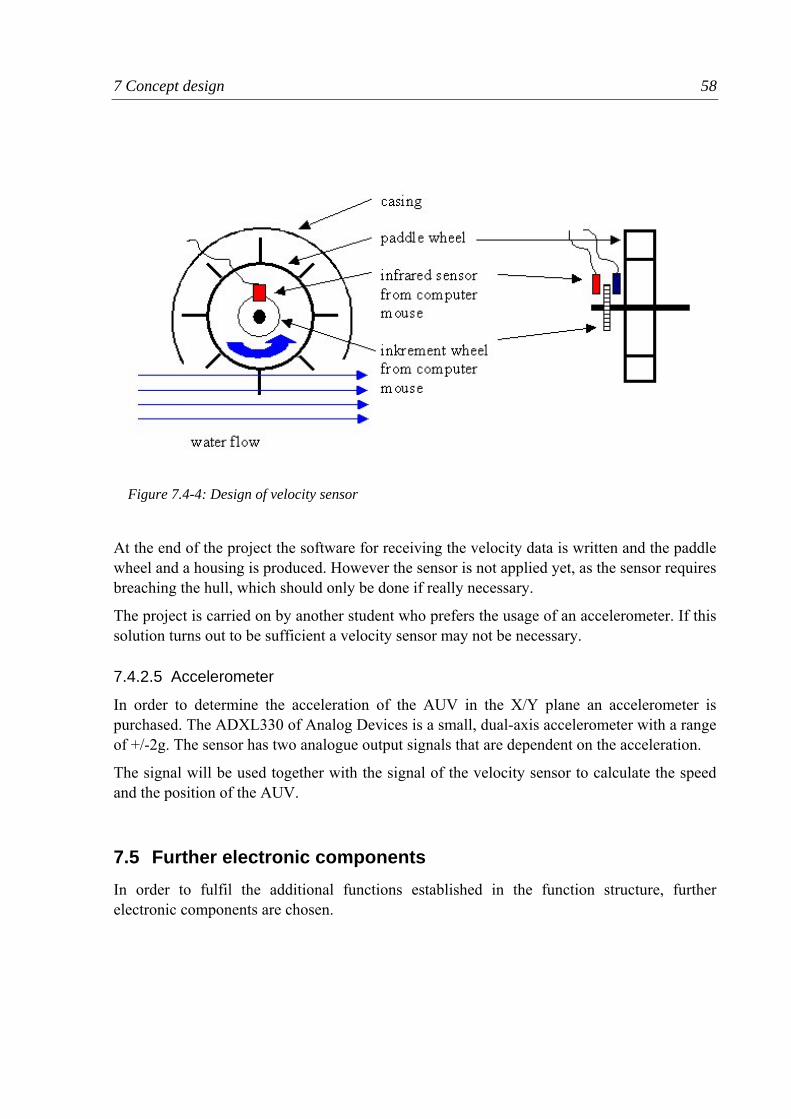
7 Concept design 58
At the end of the project the software for receiving the velocity data is written and the paddle wheel and a housing is produced. However the sensor is not applied yet, as the sensor requires breaching the hull, which should only be done if really necessary.
The project is carried on by another student who prefers the usage of an accelerometer. If this solution turns out to be sufficient a velocity sensor may not be necessary.
7.4.2.5 Accelerometer
In order to determine the acceleration of the AUV in the X/Y plane an accelerometer is purchased. The ADXL330 of Analog Devices is a small, dual-axis accelerometer with a range of +/-2g. The sensor has two analogue output signals that are dependent on the acceleration.
The signal will be used together with the signal of the velocity sensor to calculate the speed and the position of the AUV.
7.5 Further electronic components In order to fulfil the additional functions established in the function structure, further electronic components are chosen.
Figure 7.4-4: Design of velocity sensor
7 Concept design 59
7.5.1 Camera The function “provide vision” requires a camera system. The standard Eyebot camera (EyeCam) is used. The camera is mounted on a small servo motor in the front bulb of the submarine. The camera can tilt forward and downward and will be used for task like object recognition. The camera has a resolution of 80x60 pixels and can be directly attached to the Eyebot over the camera interface. The development of the vision software will be done by a student who is succeeding the project.
7.5.2 Battery The AUV needs an energy source for driving the controller and the actuators. A rechargeable battery is the best option, because they are cheap and easy to reload. Normally in robotic applications a battery should be as light as possible. In the case of the AUV a heavy battery is not a problem, as weights for trimming are necessary anyway and the USAL-Shell needs at least 3kg of extra weight to submerge. The best option is the usage of inexpensive lead-acid batteries.
The battery has to fulfil the space requirements, but should have the biggest capacity possible to increase the possible operation time of the AUV.
A 7Ah battery (Xinshun 6-FM-7) is chosen, as it fits into the AUV, so that there is still space for electronic components.
7.5.3 Bluetooth communicator In order to change programs on the controller, to send sensor data from the AUV and to drive the AUV remotely, a wireless communication is helpful.
Bluetooth adapters that are relatively inexpensive can easily be attached to the RS232 port of the Eyebot controller. The range of Bluetooth is less than 30m in air, and underwater less than 30cm. However, the possibility to change the program on the AUV without opening it is a big advantage.
The Initium Bluetooth module is attached to the Eyebot. A Bluetooth USB-dongle can be used at a notebook, so a communication, e.g. from the side of a pool is possible.
7.5.4 Infrared sensor An infrared sensor can be attached to the Eyebot. With this sensor it is possible to control the Eyebot with a standard TV-remote control. The application of the sensor is straightforward and with the remote control the function of the Eyebot buttons can be replaced.
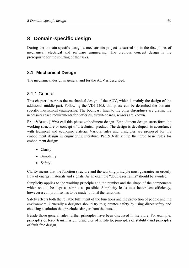
8 Domain-specific design 60
8 Domain-specific design During the domain-specific design a mechatronic project is carried on in the disciplines of mechanical, electrical and software engineering. The previous concept design is the prerequisite for the splitting of the tasks.
8.1 Mechanical Design The mechanical design in general and for the AUV is described.
8.1.1 General This chapter describes the mechanical design of the AUV, which is mainly the design of the additional middle part. Following the VDI 2205, this phase can be described the domain-specific mechanical engineering. The boundary lines to the other disciplines are drawn, the necessary space requirements for batteries, circuit-boards, sensors are known.
PAHL&BEITZ (1996) call this phase embodiment design. Embodiment design starts form the working structure or concept of a technical product. The design is developed, in accordance with technical and economic criteria. Various rules and principles are proposed for the embodiment design in engineering literature. Pahl&Beitz set up the three basic rules for embodiment design:
• Clarity
• Simplicity
• Safety
Clarity means that the function structure and the working principle must guarantee an orderly flow of energy, materials and signals. As an example “double restraints” should be avoided.
Simplicity applies to the working principle and the number and the shape of the components which should be kept as simple as possible. Simplicity leads to a better cost-efficiency, however a compromise has to be made to fulfil the functions.
Safety affects both the reliable fulfilment of the functions and the protection of people and the environment. Generally a designer should try to guarantee safety by using direct safety and choosing a solution that precludes danger from the outset.
Beside those general rules further principles have been discussed in literature. For example: principles of force transmission, principles of self-help, principles of stability and principles of fault free design.
8 Domain-specific design 61
8.1.2 Mechanical design of the AUV With the decision for the sensors, actuators, battery and controller that are used, the mechanical design of the AUV can be made. An operating structure is established. Approximate calculation show that the weight of the additional elements is compensated to the increasing volume of the AUV. The buoyancy is positive and can be adjusted with additional weights.
Figure 8.1-1: General concept of AUV
The general placement of the elements and the general design are sketched in Figure 8.1-1. The battery with the Eyebot controller on top is mounted in the translucent front part of the AUV. Four PSD-sensor are mounted inside the hull, two looking sideways, one looking downward and one looking forward. The camera is mounted in the front bulb and looks downward. The Bluetooth module fits next to the Eyebot. The pressure sensor is applied on an amplifier board and is mounted between battery and the front end plate. A tube is set through the plate to get the pressure to the sensor. The velocity sensor with the paddle wheel will be mounted on the outside of the AUV with a cable going through the hull.
The middle part is built of rotating aluminium work pieces. Two circular plates close the front and the back part of the AUV. The shape of the plates is identical to that of the replaced plastic middle plate. The two plates are connected by a pair of rods and a pair of tubes. The tubes are used to get cables from the back part to the front. The motor-propeller combination is mounted between the plates. A plastic tube, housing the cables to the motor, goes through one of the plates. So the sealing is around the plastic tube, but no loose cables have to pierce the hull. The motor is attached to the second plate with a bracket. Around the propeller a cylindrical ring is mounted. Firstly to protect the propeller and secondly to increase the efficiency by the constriction that forces the water to flow through the blades.
In the back part of the AUV an amplifier board is mounted, that drives the additional motor. The stern motor is used, as it was in the USAL-submarine. The servo motor is replaced by a servo with a higher torque. The original linkage to the paddles is used.
The mechanical design has to fulfil several requirements:
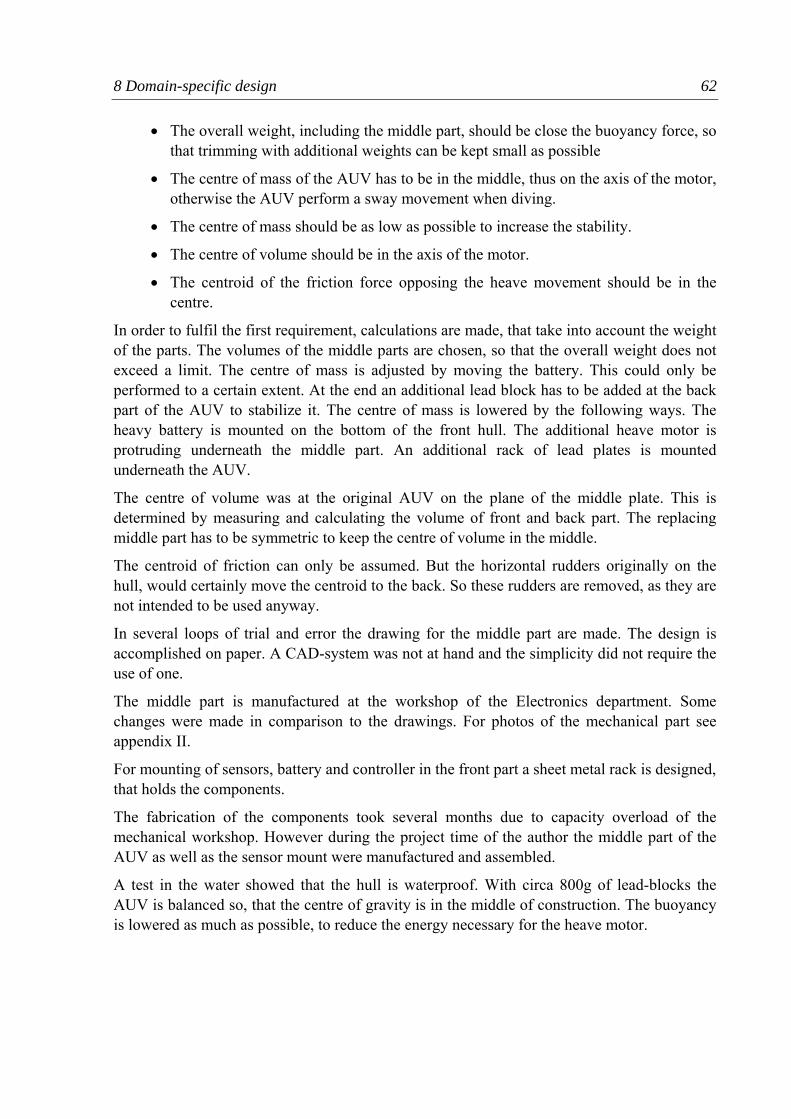
8 Domain-specific design 62
• The overall weight, including the middle part, should be close the buoyancy force, so that trimming with additional weights can be kept small as possible
• The centre of mass of the AUV has to be in the middle, thus on the axis of the motor, otherwise the AUV perform a sway movement when diving.
• The centre of mass should be as low as possible to increase the stability.
• The centre of volume should be in the axis of the motor.
• The centroid of the friction force opposing the heave movement should be in the centre.
In order to fulfil the first requirement, calculations are made, that take into account the weight of the parts. The volumes of the middle parts are chosen, so that the overall weight does not exceed a limit. The centre of mass is adjusted by moving the battery. This could only be performed to a certain extent. At the end an additional lead block has to be added at the back part of the AUV to stabilize it. The centre of mass is lowered by the following ways. The heavy battery is mounted on the bottom of the front hull. The additional heave motor is protruding underneath the middle part. An additional rack of lead plates is mounted underneath the AUV.
The centre of volume was at the original AUV on the plane of the middle plate. This is determined by measuring and calculating the volume of front and back part. The replacing middle part has to be symmetric to keep the centre of volume in the middle.
The centroid of friction can only be assumed. But the horizontal rudders originally on the hull, would certainly move the centroid to the back. So these rudders are removed, as they are not intended to be used anyway.
In several loops of trial and error the drawing for the middle part are made. The design is accomplished on paper. A CAD-system was not at hand and the simplicity did not require the use of one.
The middle part is manufactured at the workshop of the Electronics department. Some changes were made in comparison to the drawings. For photos of the mechanical part see appendix II.
For mounting of sensors, battery and controller in the front part a sheet metal rack is designed, that holds the components.
The fabrication of the components took several months due to capacity overload of the mechanical workshop. However during the project time of the author the middle part of the AUV as well as the sensor mount were manufactured and assembled.
A test in the water showed that the hull is waterproof. With circa 800g of lead-blocks the AUV is balanced so, that the centre of gravity is in the middle of construction. The buoyancy is lowered as much as possible, to reduce the energy necessary for the heave motor.
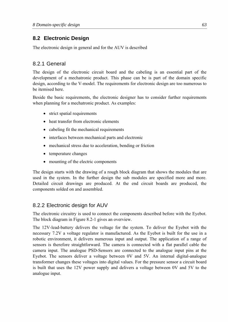
8 Domain-specific design 63
8.2 Electronic Design The electronic design in general and for the AUV is described
8.2.1 General The design of the electronic circuit board and the cabeling is an essential part of the development of a mechatronic product. This phase can be is part of the domain specific design, according to the V-model. The requirements for electronic design are too numerous to be itemised here.
Beside the basic requirements, the electronic designer has to consider further requirements when planning for a mechatronic product. As examples:
• strict spatial requirements
• heat transfer from electronic elements
• cabeling fit the mechanical requirements
• interfaces between mechanical parts and electronic
• mechanical stress due to acceleration, bending or friction
• temperature changes
• mounting of the electric components
The design starts with the drawing of a rough block diagram that shows the modules that are used in the system. In the further design the sub modules are specified more and more. Detailed circuit drawings are produced. At the end circuit boards are produced, the components solded on and assembled.
8.2.2 Electronic design for AUV The electronic circuitry is used to connect the components described before with the Eyebot. The block diagram in Figure 8.2-1 gives an overview.
The 12V-lead-battery delivers the voltage for the system. To deliver the Eyebot with the necessary 7.2V a voltage regulator is manufactured. As the Eyebot is built for the use in a robotic environment, it delivers numerous input and output. The application of a range of sensors is therefore straightforward. The camera is connected with a flat parallel cable the camera input. The analogue PSD-Sensors are connected to the analogue input pins at the Eyebot. The sensors deliver a voltage between 0V and 5V. An internal digital-analogue transformer changes these voltages into digital values. For the pressure sensor a circuit board is built that uses the 12V power supply and delivers a voltage between 0V and 5V to the analogue input.
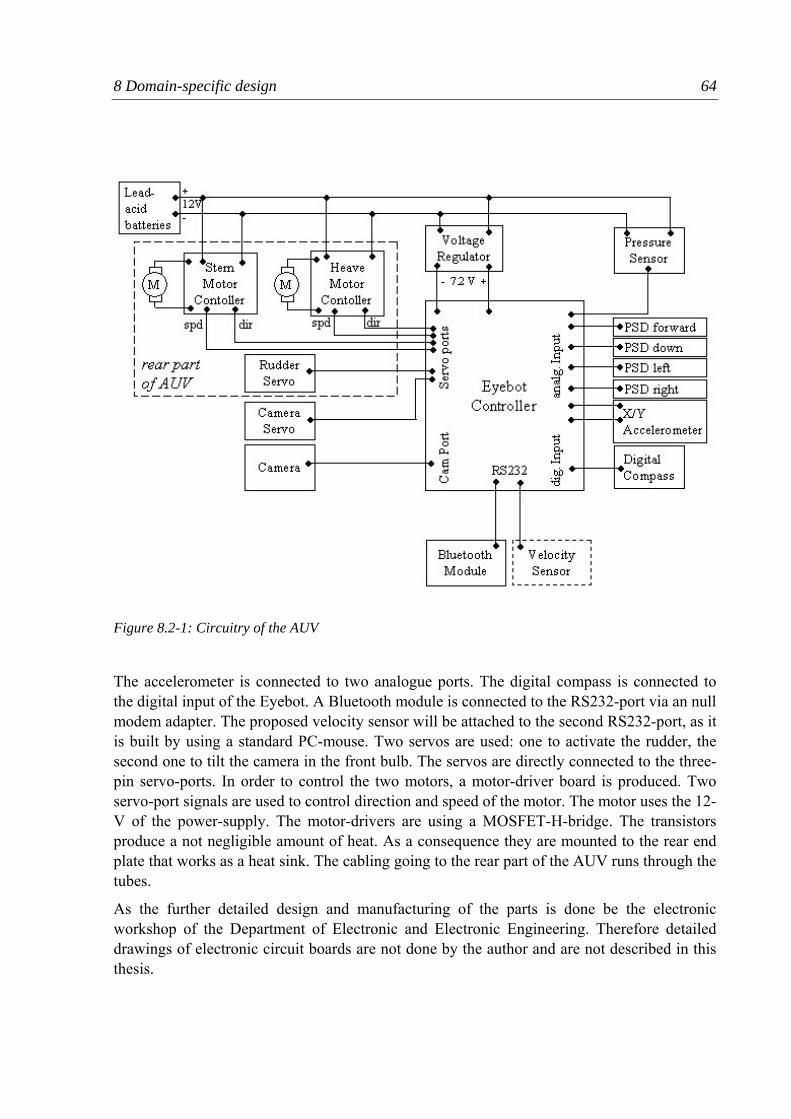
8 Domain-specific design 64
The accelerometer is connected to two analogue ports. The digital compass is connected to the digital input of the Eyebot. A Bluetooth module is connected to the RS232-port via an null modem adapter. The proposed velocity sensor will be attached to the second RS232-port, as it is built by using a standard PC-mouse. Two servos are used: one to activate the rudder, the second one to tilt the camera in the front bulb. The servos are directly connected to the three-pin servo-ports. In order to control the two motors, a motor-driver board is produced. Two servo-port signals are used to control direction and speed of the motor. The motor uses the 12-V of the power-supply. The motor-drivers are using a MOSFET-H-bridge. The transistors produce a not negligible amount of heat. As a consequence they are mounted to the rear end plate that works as a heat sink. The cabling going to the rear part of the AUV runs through the tubes.
As the further detailed design and manufacturing of the parts is done be the electronic workshop of the Department of Electronic and Electronic Engineering. Therefore detailed drawings of electronic circuit boards are not done by the author and are not described in this thesis.
Figure 8.2-1: Circuitry of the AUV
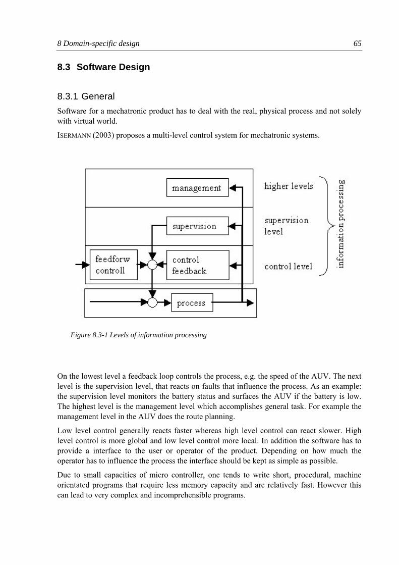
8 Domain-specific design 65
8.3 Software Design
8.3.1 General Software for a mechatronic product has to deal with the real, physical process and not solely with virtual world.
ISERMANN (2003) proposes a multi-level control system for mechatronic systems.
On the lowest level a feedback loop controls the process, e.g. the speed of the AUV. The next level is the supervision level, that reacts on faults that influence the process. As an example: the supervision level monitors the battery status and surfaces the AUV if the battery is low. The highest level is the management level which accomplishes general task. For example the management level in the AUV does the route planning.
Low level control generally reacts faster whereas high level control can react slower. High level control is more global and low level control more local. In addition the software has to provide a interface to the user or operator of the product. Depending on how much the operator has to influence the process the interface should be kept as simple as possible.
Due to small capacities of micro controller, one tends to write short, procedural, machine orientated programs that require less memory capacity and are relatively fast. However this can lead to very complex and incomprehensible programs.
Figure 8.3-1 Levels of information processing
8 Domain-specific design 66
In the case of the Eyebot it is possible to write programs in C++. This enables an object-orientated approach. When writing object-orientated it is possible to encapsulate certain elements of the mechatronic system into a virtual object. This reduces the complexity of the program, as the internal structure of an object can be hided into a black box.
Generally it can be said with the software many problems due to the mechanical or electrical inaccuracies can be solved. However a robust design and accurate sensors prevent the extensive use of filtering and compensation. The more stable the mechatronic basis is, the simpler the software part can be.
8.3.2 Software for AUV Due to delays in the making of the mechanical and electronic parts, the test phase of the AUV could not be started in time. The control software that provides the autonomy of the vehicle will be written by a student that succeeds the author.
However the author wrote the programs that enable the remote control of the AUV by a TV-remote. An object-orientated approach is used. For each real component a software-class is created. For example a class for the motors, that provide functions like set_direction() to change the direction of the motor or increase() to increase the speed of the motor by one step. Inside each class the functionality of the component is hidden. For example the hysteresis of the rudders is compensated. When generating a rudder object this compensations no longer needs to be taken in to account
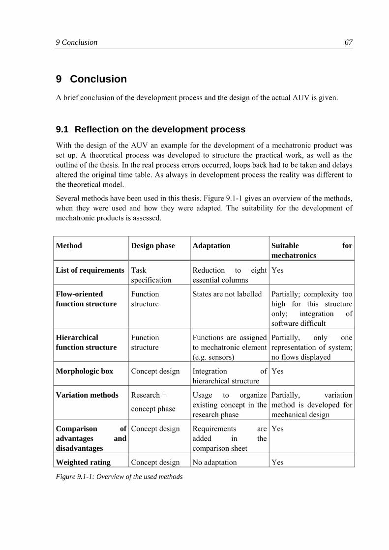
9 Conclusion 67
9 Conclusion A brief conclusion of the development process and the design of the actual AUV is given.
9.1 Reflection on the development process With the design of the AUV an example for the development of a mechatronic product was set up. A theoretical process was developed to structure the practical work, as well as the outline of the thesis. In the real process errors occurred, loops back had to be taken and delays altered the original time table. As always in development process the reality was different to the theoretical model.
Several methods have been used in this thesis. Figure 9.1-1 gives an overview of the methods, when they were used and how they were adapted. The suitability for the development of mechatronic products is assessed.
Method Design phase Adaptation Suitable for mechatronics
List of requirements Task specification
Reduction to eight essential columns
Yes
Flow-oriented function structure
Function structure
States are not labelled Partially; complexity too high for this structure only; integration of software difficult
Hierarchical function structure
Function structure
Functions are assigned to mechatronic element (e.g. sensors)
Partially, only one representation of system; no flows displayed
Morphologic box Concept design Integration of hierarchical structure
Yes
Variation methods Research +
concept phase
Usage to organize existing concept in the research phase
Partially, variation method is developed for mechanical design
Comparison of advantages and disadvantages
Concept design Requirements are added in the comparison sheet
Yes
Weighted rating Concept design No adaptation Yes
Figure 9.1-1: Overview of the used methods
9 Conclusion 68
The methods could be successfully used with slight modifications. Besides those a vast amount of methods have been developed in mechanical, electronic and software design. Probably many of them can be transferred into another discipline or be used in interdisciplinary development. A research project on transferring methods into other disciplines could lead to new interesting approaches. Two examples: can the variation method and morphologic boxes used in software design? Is the object-oriented approach suitable for the development of mechanical products?
Complexity in mechatronic products is difficult to handle. One singular function structure is often not sufficient to display a mechatronic system. In the case of the AUV additionally to the flow-oriented function model, a hierarchical function structure is developed. In the later concept phase this hierarchy is used again to organise the solutions in a morphologic box. The usage of methods should not be seen as a strict frame, but a guideline that can be altered to the concrete situation.
As regards the V-model, it was used as a base for a function model specific for the AUV-development. A greater emphasis was laid on the steps “task specification” and “research” which are less detailed in the VDI 2206. The idea of generating a interdisciplinary system design, followed by domain-specific design and the final system integration was adopted. The V-model in general is a useful to organise a group of interdisciplinary engineers. In this case the author worked alone and the organisation was easier. The V-model is just a basic frame for mechatronic development. The gaps between the disciplines, regarding domain-specific development methodologies, software tools, notation etc. are still broad. Future research should aim to find a global approach for the coalescences of the disciplines.
For the author as a mechanical engineer it was interesting and instructive to look into other disciplines. However it is hard to acquire a excellent knowledge in every discipline. Therefore the specific education in each discipline and specialists for certain tasks will still be necessary in future. A broader education on top of that will certainly help in the increasingly mechatronic development processes.
At the end of the author’s work at the Robotics Lab the mechanical part of the AUV has been finished. The mechanical and electrical workshops delayed the manufacturing of the necessary parts by several months, due to heavy workload. The AUV therefore could not be completed as the amplifier board for the motors was not finished by the end. Test in water, besides a balancing and water tightness test could not be conducted. However, with the construction of the AUV a groundwork was laid for the future entry into high school competitions.
9.2 Future work and recommendations As the electronic design is yet to be finished, the AUV is not completed. Tests have to been made to find out the dynamic behaviour of the AUV. During the later stage of the development doubts occurred if the rotating of the motor will spin the whole AUV. The hope is that due to the small buoyancy, the motor will not spinning fast and the counter rotation of
9 Conclusion 69
the AUV can be compensated, with the rudders when it is moving. Another possibility would be the purchase of a trimming cell for the depth controlling.
The software for the autonomous mode of the AUV has to be written. First of all a low-level control scheme for depth, heading, and velocity has to be set up. The object detection software has to be developed. A management software has to plan and coordinate the tasks.
Future work might be necessary regarding the obstacle avoidance by means of the PSD-sensors. If these sensors turn out not to be sufficient, the purchase of Sonar sensor has to be considered. Sonar sensors are more expansive, but should give a further and more accurate distance measurement.
9.3 Final word With a limited budget a small autonomous underwater vehicle has been developed. The mechanical structure is produced. Future development and improvement with show that this compared to other AUV projects, smaller and cheaper concept will succeed.
10 References 70
10 References ABDO, A.; BAUTISTA, A.; BÉLANGER, F.; BESNER, D.; DROLET, M.; ELBADRI, M.; KOSZANKSKI, L.; LAWRENCE, B.; MILIAUSKAITE, A.; MILNER, M.; MUSTIÈRE, F.; NGUYEN, S.; NIYONKURU, E.; POISSON, E.; SABIHUDDIN, S. (2005)
A Second-Generation AUV Ottawa: University of Otawa, Advanced Robotic Innovations Society in Engineering [taken out on 3.9.2005, URL: http://www.auvsi.org/competitions/2005/JournalPapers/Cornell.pdf]
APGAR, J.; BOBER, M.; CHENG, W.; EDELSON, J.; FURTADO, J.; HOWELL, B.; HUANG, A.; KENYON, S.; KNAIAN, A.; NEWBURG, D.; SANTIAGO, J.; TZERANIS, D. (2005)
ORCA-VIII: An Autonomous Underwater Vehicle Cambridge: Massachusetts Institute of Technology; Project ORCA [taken out on 2.9.2005, URL: http://web.mit.edu/orca/www/journalpapers/paper05.pdf]
AUVSI (2005) Association for Unmanned Vehicle Systems International; Student AUV Competitions [taken out on:17.08.05; URL http:www.auvsi.org/competitions/water.cfm]
BARRETT, D.(1994) The Design of a Flexible Hull Undersea Vehicle Propelled by an Oscillating Foil Cambridge: MIT, Masters Thesis 1994
BERNARDI, M.; BLEY, H.; SCHMITT, B. Integrating a Mechatronics-oriented Development Process into a Development Department Proceedings of the 37th CIRP International Seminar on Manufaturing System, pp. 265-270 Budapest: Hungary, 2004
BRUTZMANN, D.; HEALEY, T.; MARCO, D.; MCGHEE, B. (1997) The Phoenix Autonomous Underwater Vehicle Monterey: Center for Autonomous Underwater Vehicle Research, 1997 [taken out on 06.05.2005, URL: http://web.nps.navy.mil/~brutzman/aimr.pdf]
CORRIGAN, J.; BURMAN, B.; BYRON, J.; JÄGER, A.; JANUSZ, R.; LAFERRIERE, A.; LEUZARDER, R.; PATTY, C.; SITNIK, G.; WERNER, F.; MILLER, J. TYCE , R. (2005)
Prowler VI Narrangansett: University of Rhode Island, AUV Team 2005 [taken out on 3.9.2005, URL: http://ocean.oce.uri.edu/auvteam/journal.pdf]
CUAUV (2005) Cornell AUVSI Competition Entry 2005 Ithaca: Cornell University Autonomous Underwater Vehicle Team 2005 [taken out on 2.9.2005, URL: http://www.auvsi.org/competitions/2005/JournalPapers/Cornell.pdf]
10 References 71
DROHER, R.; JANTZEN, C.; NG, D.; PAUL, D.; SHEARER, S.; SOPPET, T. (2005) Barracuda Mark IV Pleaston, Amador Valley High School Robotics Club 2005-10-11 [taken out on 2.9.2005 URL: http://www.auvsi.org/competitions/2005/JournalPapers/AVHS.pdf]
DUBEL, W.; GRECO, J.; CHINAULT, A.; FRANCIS, C.; BARNETT, A.; CLAYCOMB, K.; MELLING, A.; SCHWARTZ, E.; ARROYO, A. (2005)
SubjuGator 2005 Gainesville, Machine Intelligence Laboratory, University of Florida [taken out on 2.9.2005, URL: http://www.auvsi.org/competitions/2005/JournalPapers/UF.pdf]
FELGEN, L. Complexity management during the analysis of mechatronic systems Melbourne: International Conference on Engineering Design (ICED 2005)
FELKINS, J.; JOHNSTON, J.; HELBLE, T.; EADE, E. (2005) Charybdis Durhem: Duke University Robotics Team 2005 [taken out on 3.9.2005, URL: http://www.auvsi.org/competitions/2005/JournalPapers/Cornell.pdf]
GAUSEMEIER, J. (2002) From Mechatronic to Self-Optimization 20th CAD-FEM User Meeting 2002, 9.-11.Okt.2002, Friedrichshafen taken out on 1.8.2005; URL: http://www.sfb614.de/doku/von_der_Mechatronik_zur_Selbstoptimierung.pdf
GONZALEZ, L. (2004) Design, Modelling and Control of an Autonomous Underwater Vehicle Perth: UWA, Honours Thesis 2004
HORNFELD, W. (2005) Deep-C; the German AUV Development Project Bremen: Atlas Electronic GmbH, 2005 [taken out on 03.08.2005; URL: http://www.deepc-auv.de/deepc/bibliothek/pdf/South_end.pdf]
ISERMANN, R. (2003) Mechatronic Systems, Fundamentals London: Springer 2003
LARKIN, S.; SINCLAIR J. (2005) Improvement Made to the Water Buffalo Autonomous Underwater Vehicle Denver: Robotics Society, University of Colorado 2005 [taken out on 2.9.2005, URL: http://www.auvsi.org/competitions/2005/JournalPapers/UCOL.pdf]
10 References 72
LINDEMANN, U. (2005) Methodische Entwicklung technischer Produkte; Methoden flexibel und situationsgerecht anwenden Berlin: Springer 2005
LINDEMANN, U. (2004) Produktentwicklung und Konstruktion; Vorlesungsskriptum Garching: Fachschaft Maschinenbau 2004
LINDFORS, N.; PESONEN. A.; FRANCK, C.; LÄHTEINEN, V.; KUOSMANEN, P. (2003) Cabeling design utilizing 3D CAD in product development of an electric device Stockholm: International Conference of Engineering Design (ICED 19.-21. August 2003
MASSEY, B. (1998) Mechanics of Fluids, Seventh Edition Cheltenham: Stanley Thornes Ltd.
MOBILE ROBOT LAB (2005) [taken out on 5.9.2005; URL: http://robotics.ee.uwa.edu.au]
NGUYEN, T. (2004) Design of an Active Acoustic Sensor System for an Autonomous Underwater Vehicle Perth: UWA, Honour Thesis 2005
PAHL, G.; BEITZ, W. (1996) Engineering Design, A Systematic Approach London: Springer 1996
RAJAN, J.; STONE, B.; WOOD, K. (2003) Functional Modelling of Control System Stockholm: International Conference of Engineering Design, ICED03, Aug.19-21,2003
SCHWARZER, S.; OLDHAM, W. (2005) Electrical Engineering: A Introduction New York, Oxford Press 1984
SHAHIPOOR, M. (1987) A robot engineering textbook New York: Harper & Row, 1987
STREETER, V.; WYLIE, E.; BEDFORD, K. (1998) Fluid Mechanics Boston: WCB McGraw-Hill, 1998
10 References 73
YU, J.; WANG, S.; TAN, M. (2003) Design of a Free-swimming Biomimetic Robot Fish Kobe: Proceeding of the 2003 IEEE/ASME International Conference on Advanced Intelligent Mechatronics; P 95-100
YUH, J. (2000) Design and Control of Autonomous Underwater Vehicles: A Survey Autonomous Robots p7-24 The Netherlands: Kluwer Academic Publisher 2000 [taken out on 03.05.2005; URL: http://neuron-ai.tuke.sk/~hudecm/PDF_PAPERS/ DesignAndControlOfAutonomousUnderwaterrobotsASurvey.pdf]
VDI-RICHTLINIE 2206 (2004) Entwicklungsmethodik für mechatronische Produkte Düsseldorf, Verein Deutscher Ingenieure 2004
WEBER, C. (2005) What is “Complexity”? Melbourne: International Conference of Engineering Design (ICED 05), August 15-18, 2005
WIKIPEDIA, 2005A BUOYANCY [taken out on 4.9.2005; URL: http://en.wikipedia.org/wiki/buoyancy]
WIKIPEDIA, 2005B Dead Reckoning [taken out on 15.9.2005; URL: http://en.wikipedia.org/wiki/dead_reckoning]
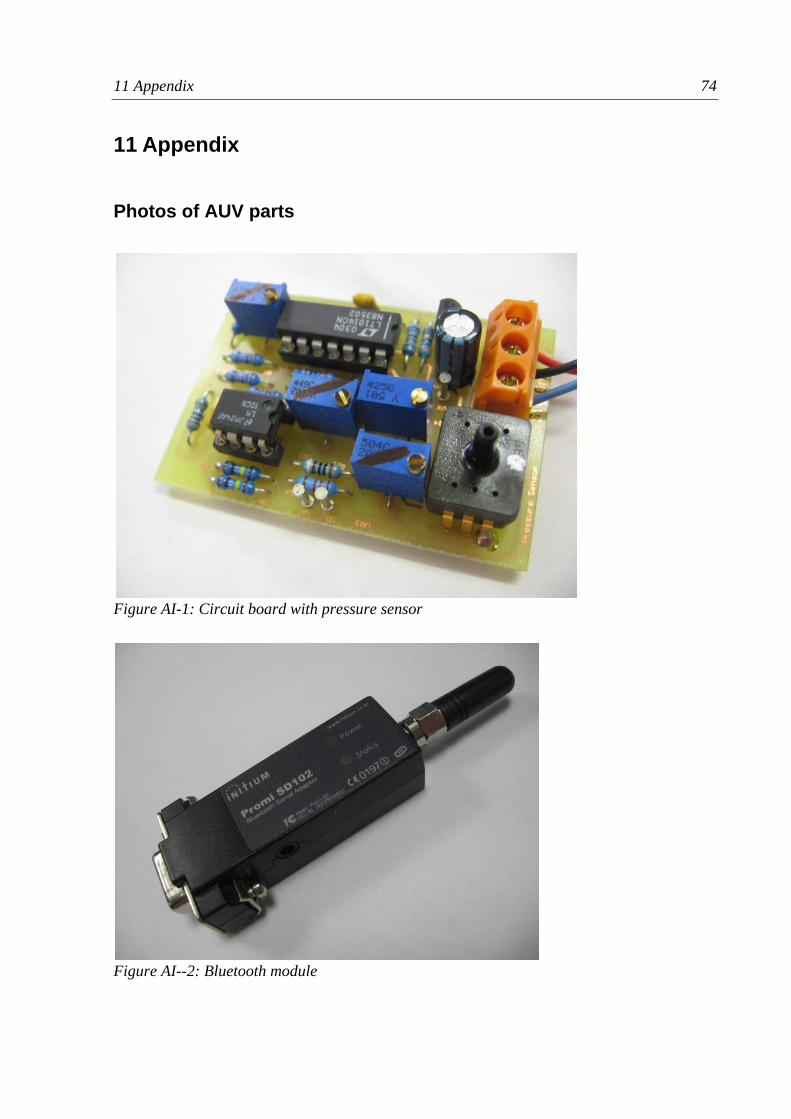
11 Appendix 74
11 Appendix
Photos of AUV parts
Figure AI-1: Circuit board with pressure sensor
Figure AI--2: Bluetooth module
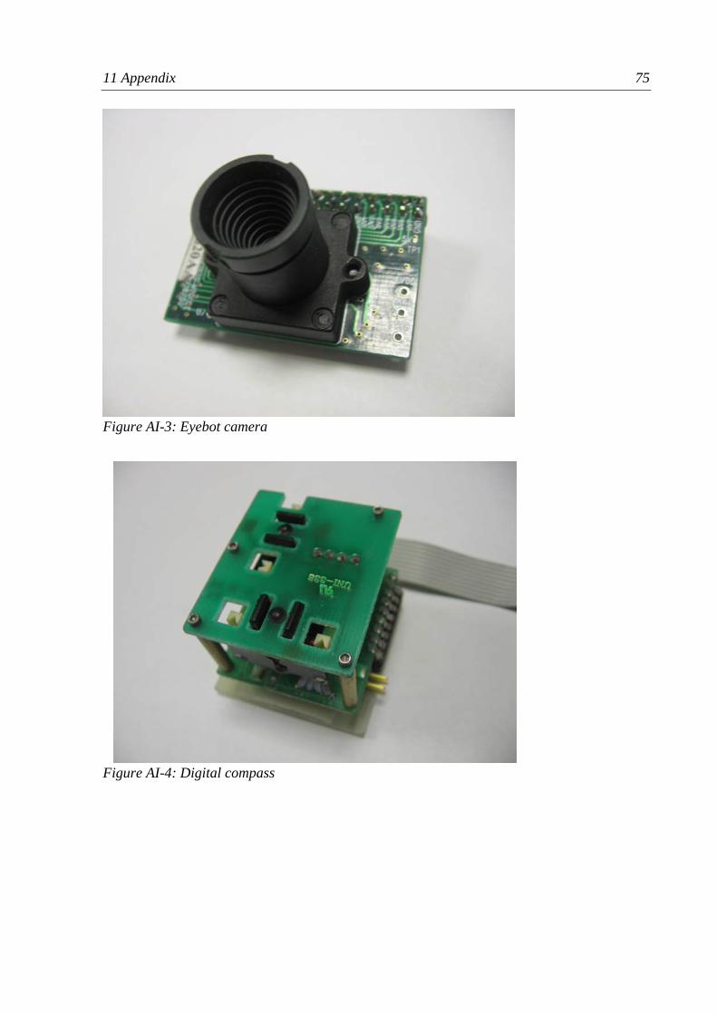
11 Appendix 75
Figure AI-3: Eyebot camera
Figure AI-4: Digital compass
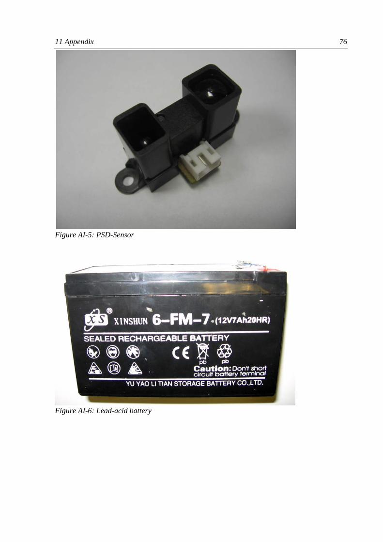
11 Appendix 76
Figure AI-5: PSD-Sensor
Figure AI-6: Lead-acid battery
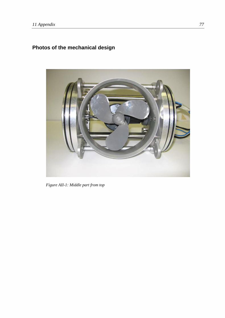
11 Appendix 77
Photos of the mechanical design
Figure AII-1: Middle part from top
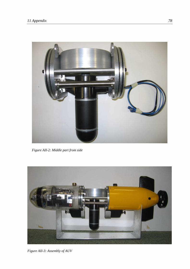
11 Appendix 78
Figure AII-2: Middle part from side
Figure AII-3: Assembly of AUV
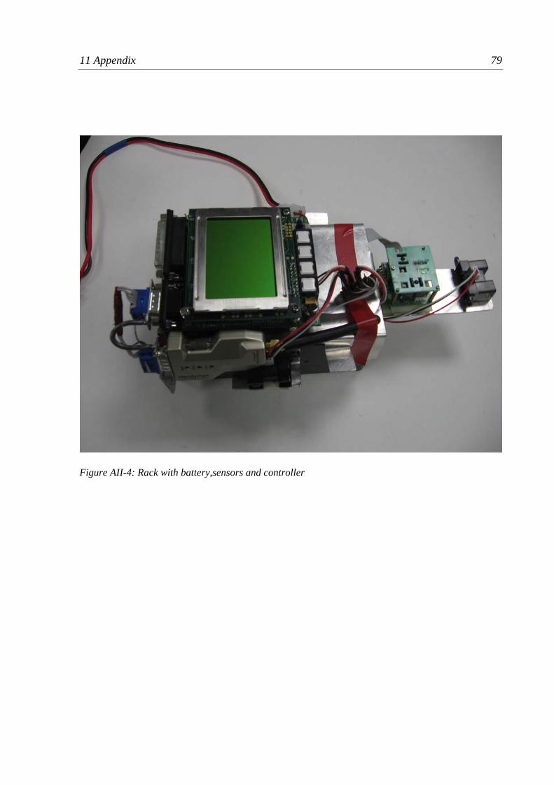
11 Appendix 79
Figure AII-4: Rack with battery,sensors and controller
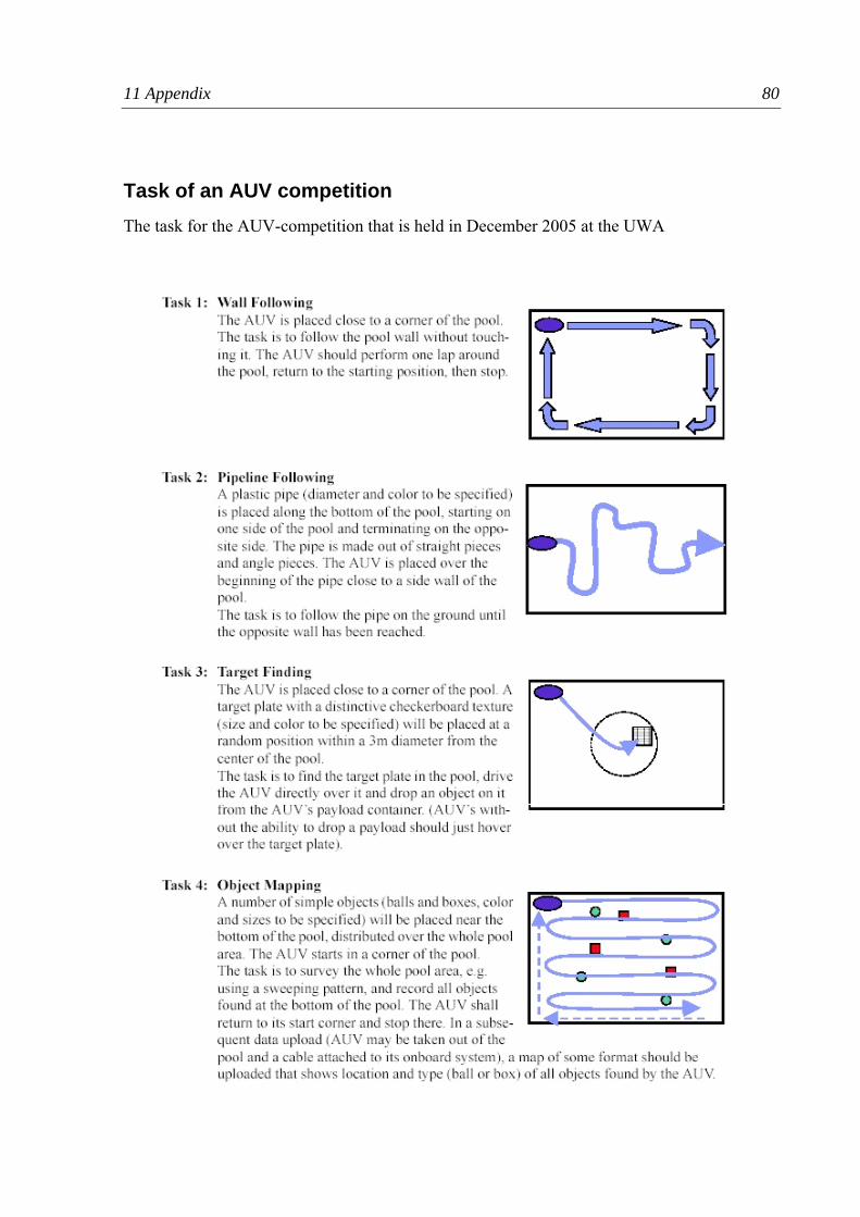
11 Appendix 80
Task of an AUV competition The task for the AUV-competition that is held in December 2005 at the UWA

11 Appendix 81