detailing and behavior of coupling beams with high ... · seismic detailing and behavior of...
TRANSCRIPT
Reference:
Lequesne, R. D., Setkit, M., Parra-Montesinos, G. J. and Wight, J. K. (2010), “Seismic Detailing and
Behavior of Coupling Beams Incorporating High-Performance Fiber Reinforced Concrete,” Antoine E.
Naaman Symposium: Four Decades of Progress in Prestressed Concrete, Fiber Reinforced Concrete and
Thin Laminate Composites, SP-272, American Concrete Institute, Farmington Hills, MI, 14 pp.
Seismic Detailing and Behavior of Coupling Beams With High-Performance Fiber Reinforced
Concrete
By Rémy Lequesne, Monthian Setkit, Gustavo Parra-Montesinos, and James K. Wight
Synopsis: This paper summarizes a series of tests performed on strain hardening High-Performance Fiber
Reinforced Concrete (HPFRC) coupling beams with span length-to-depth ratios ( /n h ) of 1.75 and 2.75. These
tests show that incorporating HPFRC simplifies the detailing required to ensure a stable response of coupling beams
subjected to earthquake induced displacement reversals. Results from five tests of precast coupling beams, three
with / 1.75n h and two with / 2.75n h , are reported herein. Strategies for embedding the precast HPFRC
coupling beams into the structural walls without interfering with boundary element reinforcement were explored.
Test results confirm that HPFRC can reliably confine diagonal reinforcement and ensure stable hysteresis behavior.
HPFRC was also found to significantly increase shear strength, thereby forcing a flexurally dominated failure mode
with modest stiffness degradation and excellent energy dissipation. A revised coupling beam design philosophy is
outlined in order to ensure ductile flexural behavior.
Keywords: Coupling Beam, High Performance Fiber Reinforced Concrete (HPFRC), Precast, Seismic, Shear
ACI member Rémy Lequesne is a PhD student at the University of Michigan, Ann Arbor. He was the 2007-2008
ACI Pankow Foundation Fellowship recipient, and is an Associate Member of ACI Committee 374, Performance-
Based Seismic Design of Concrete Buildings. His research interests include the behavior and design of reinforced
concrete members, the mechanical and structural behavior of high-performance fiber-reinforced concrete, and the
earthquake resistant design of reinforced concrete structures.
ACI member Monthian Setkit is a PhD student at the University of Michigan, Ann Arbor. His research interests
include the behavior and design of reinforced concrete, the earthquake-resistant design of reinforced concrete
structures, and fiber- reinforced concrete structures.
ACI member Gustavo J. Parra-Montesinos is an Associate Professor of civil engineering at the University of
Michigan, Ann Arbor. He is Chair of ACI Committee 335, Composite and Hybrid Structures; and a member of ACI
Committee 318, Structural Building Code, and Joint ACI-ASCE Committee 352, Joints and Connections in
Monolithic Concrete Structures. His research interests include the behavior and design of reinforced concrete,
hybrid steel-concrete, and fiber reinforced concrete structures.
James K. Wight, FACI, is a Professor of civil engineering at the University of Michigan, Ann Arbor. He is Past
Chair of ACI Committee 318, Structural Concrete Building Code, ACI Committee 318-E, Shear and Torsion, and is
a member of Joint ACI-ASCE Committees 352, Joints and Connections in Monolithic Concrete Structures, and 445,
Shear and Torsion. His research interests include the earthquake-resistant design of reinforced concrete structures
and the use of high-performance fiber-reinforced concrete in critical members or regions of such structures.
INTRODUCTION
Concrete structural wall systems are commonly used as the primary lateral force resisting system for both
medium-rise concrete and steel frame structures. Due to their stiffness and strength, structural walls attract a
considerable amount of lateral force while undergoing earthquake induced displacement reversals, requiring both
ductility and damage tolerance. The efficiency of a structural wall system can be improved through proper coupling
of two or more consecutive walls through the use of short coupling beams. This wall coupling reduces the demand
for flexural rigidity of the individual walls by taking advantage of their axial stiffness and the distance between them
to provide additional resistance to overturning moment.
For satisfactory performance of this structural system during a seismic event, the short coupling beams
must retain a significant strength through large displacement reversals, while suffering only a modest degradation of
stiffness. For coupling beam span-to-depth ratios of less than two, it has been shown1 that special diagonal
reinforcement is required to eliminate the development of a sliding shear failure, and thus, provide adequate ductility
and stiffness retention to achieve the design goals of the system. However, the reinforcement detailing required to
ensure a stable coupling beam behavior is difficult to construct, and often fails to maintain the integrity of the full
concrete element through large displacement reversals. Other alternatives have been proposed and investigated2,3,4,
including various reinforced concrete, steel, and hybrid steel-concrete coupling beam designs. Of these potential
solutions, steel and hybrid steel-concrete coupling beams exhibit the most favorable response to reversed cyclic
loading, and have begun to find their way into design practice. However, despite the improved hysteresis behavior
achievable with steel coupling beams, providing proper anchorage of the steel section without disrupting
reinforcement in the structural wall remains a significant challenge to engineers and contractors.
Recent work on very short coupling beams ( / 1.0n h )5,6 demonstrated the potential for strain hardening,
High-Performance Fiber Reinforced Concrete (HPFRC) to provide improved ductility over more traditional concrete
coupling beams, while simplifying detailing requirements. Fiber reinforced concrete takes advantage of the inclusion
of randomly disbursed fibers within the concrete matrix to provide enhanced transfer of tensile stresses across
cracks. When used in sufficient amounts some types of fibers may lead to a strain hardening tensile response, in
which case the material is referred to as a high-performance fiber reinforced concrete. On a structural scale, this
strain hardening property translates into increased shear resistance, damage tolerance, and better stiffness retention7.
Further, HPFRC has been shown to provide confinement to steel reinforcement and superior bond with reinforcing
bars8.
RESEARCH SIGNIFICANCE
The implications of using precast HPFRC coupling beams on the constructability of coupled walls, and on
the ductility and damage tolerance of these systems when subjected to displacement reversals, may be appreciable.
The experimental work described herein seeks to quantify these benefits and to provide engineers with a practical
design alternative to current code compliant coupling beam designs. Test results show that HPFRC adequately
confines the diagonal reinforcement, eliminating the need for cumbersome special confinement for these bars. These
results also show that the area of diagonal reinforcement can be significantly reduced when HPFRC is used, and that
much of the difficult detailing requirements for coupling beams can be relaxed without sacrificing performance.
PREVIOUS RESEARCH
In 1971, Paulay9 demonstrated that the development of a sliding shear failure mechanism could not be
adequately controlled in short, highly stressed coupling beams with moment frame-type reinforcement. The use of
diagonal reinforcement was then investigated to resist shear in coupling beams1,10, and a remarkable improvement
in both strength and ductility was demonstrated experimentally. This diagonal reinforcement approach has been
accepted by the ACI Building Code11, and is required for short and highly stressed coupling beams, where
/ .n h 2 0 and 4 ' , [psi] (0.33 ' , [MPa])u c cw c cwV f A f A , where: n clear span of coupling beam, h height
of coupling beam, uV shear demand, correction factor for lightweight concrete, 'cf compressive strength of
concrete, and cwA gross cross-sectional area of coupling beam. Unfortunately, this diagonal reinforcement scheme
requires substantial confinement of either the diagonals themselves or of the coupling beam section as a whole.
These complications12 often cause the construction of coupling beams and coupled walls to control the construction
schedule in seismic zones.
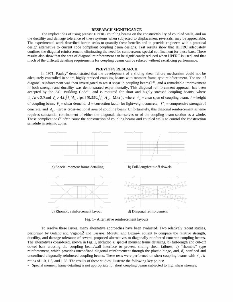
Fig. 1– Alternative reinforcement layouts
To resolve these issues, many alternative approaches have been evaluated. Two relatively recent studies,
performed by Galano and Vignoli2 and Tassios, Moretti, and Bezas4, sought to compare the relative strength,
ductility, and damage tolerance of several proposed alternatives to diagonally reinforced concrete coupling beams.
The alternatives considered, shown in Fig. 1, included a) special moment frame detailing, b) full-length and cut-off
dowel bars crossing the coupling beam/wall interface to prevent sliding shear failures, c) “rhombic” type
reinforcement, which provides unconfined diagonal reinforcement through the plastic hinge, and, d) confined and
unconfined diagonally reinforced coupling beams. These tests were performed on short coupling beams with /n h
ratios of 1.0, 1.5, and 1.66. The results of these studies illustrate the following key points: • Special moment frame detailing is not appropriate for short coupling beams subjected to high shear stresses.
a) Special moment frame detailing b) Full-length/cut-off dowels
c) Rhombic reinforcement layout d) Diagonal reinforcement
• Dowel bars crossing the coupling beam/wall interface were shown to help prevent sliding shear failures, but
could not prevent stiffness degradation and severe pinching in the hysteresis response.
• A rhombic layout of diagonal reinforcement requires less complicated detailing than diagonally reinforced
coupling beams, and exhibited less stiffness degradation than coupling beams detailed as special moment frames.
However, pinching of the hysteresis loops was still present.
• Of the reinforced concrete options considered, confined diagonal reinforcement appeared to provide the most
stable behavior and highest energy dissipation. It was noted that providing sufficient confinement to ensure stability
of the diagonal bars is “indispensable”, despite the significant field placement difficulties.
Steel and hybrid steel-concrete alternatives have also been evaluated, as discussed by Harries, Gong, and
Shahrooz3. When properly detailed and fully anchored to the adjoining structural walls, these alternatives have been
shown to respond very favorably to cyclic shear, showing stable behavior with wide hysteresis loops. Unfortunately,
the steel elements require a long embedment into the adjoining structural walls to ensure a full development of
flexural and shear capacities, which inevitably interferes with critical transverse reinforcement required for
confinement in the boundary regions of the structural walls.
MATERIAL PROPERTIES
Recent work at the University of Michigan13 has led to the development of a highly flowable HPFRC with a
1.5% volume fraction of high-strength hooked steel fibers. The properties of the fibers, as specified by the
manufacturer, are summarized in Table 1. This mixture was selected for use in all of the coupling beam tests
described herein. Results from compressive tests on 4 in. by 8 in. (100 mm by 200 mm) cylinders at 28 days and
near the test dates are shown in Table 2. These test day values of 'cf are used throughout this paper. The
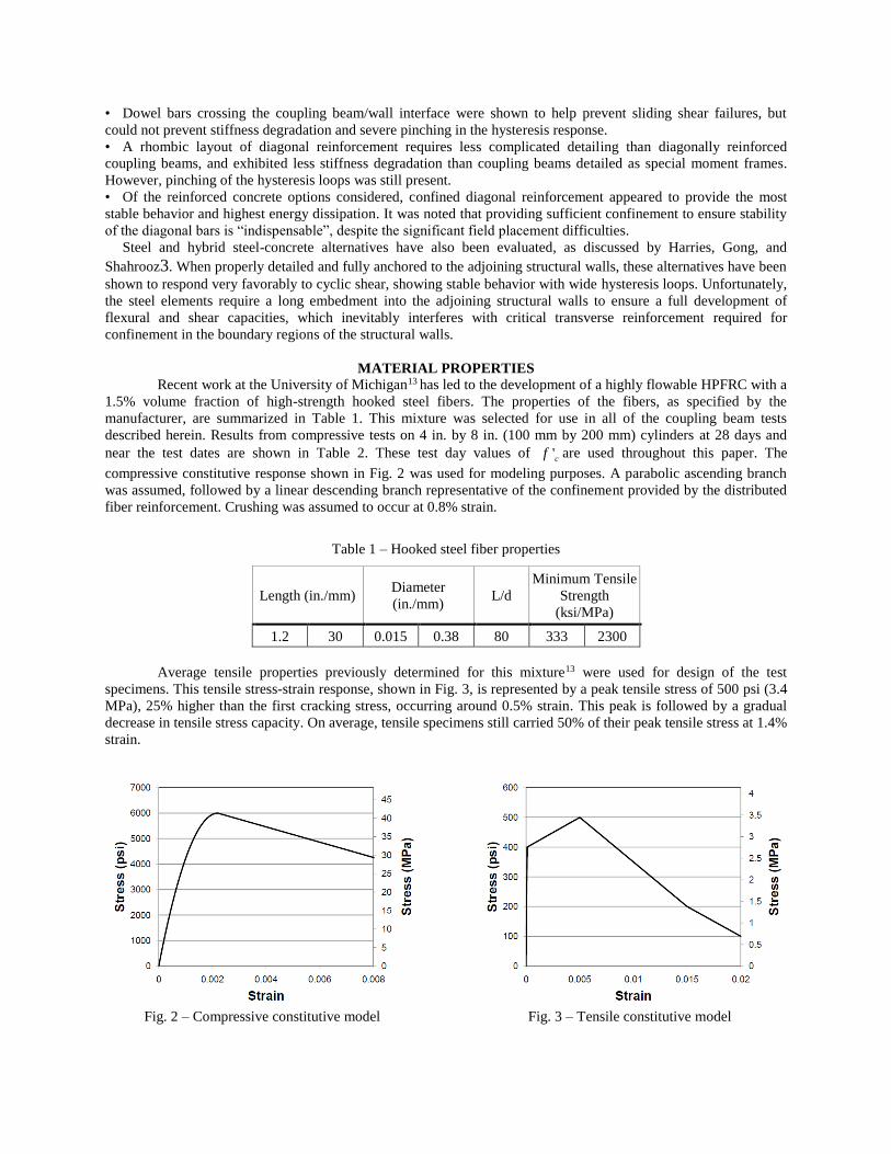
compressive constitutive response shown in Fig. 2 was used for modeling purposes. A parabolic ascending branch
was assumed, followed by a linear descending branch representative of the confinement provided by the distributed
fiber reinforcement. Crushing was assumed to occur at 0.8% strain.
Table 1 – Hooked steel fiber properties
Length (in./mm) Diameter
(in./mm) L/d
Minimum Tensile
Strength
(ksi/MPa)
1.2 30 0.015 0.38 80 333 2300
Average tensile properties previously determined for this mixture13 were used for design of the test
specimens. This tensile stress-strain response, shown in Fig. 3, is represented by a peak tensile stress of 500 psi (3.4
MPa), 25% higher than the first cracking stress, occurring around 0.5% strain. This peak is followed by a gradual
decrease in tensile stress capacity. On average, tensile specimens still carried 50% of their peak tensile stress at 1.4%
strain.
Fig. 2 – Compressive constitutive model
Fig. 3 – Tensile constitutive model
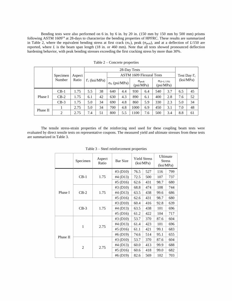
Bending tests were also performed on 6 in. by 6 in. by 20 in. (150 mm by 150 mm by 500 mm) prisms
following ASTM 160914 at 28-days to characterize the bending properties of HPFRC. These results are summarized
in Table 2, where the equivalent bending stress at first crack (σfc), peak (σpeak), and at a deflection of L/150 are
reported, where L is the beam span length (18 in. or 460 mm). Note that all tests showed pronounced deflection
hardening behavior, with peak bending stresses exceeding the first cracking stress by more than 30%.
Table 2 – Concrete properties
Specimen
Number
Aspect
Ratio
28-Day Tests
Test Day f'c
(ksi/MPa) f'c (ksi/MPa)
ASTM 1609 Flexural Tests
σfc (psi/MPa) σpeak
(psi/MPa)
σ(δ=L/150)
(psi/MPa)
Phase I
CB-1 1.75 5.5 38 640 4.4 930 6.4 540 3.7 6.5 45
CB-2 1.75 6.1 42 630 4.3 890 6.1 400 2.8 7.6 52
CB-3 1.75 5.0 34 690 4.8 860 5.9 330 2.3 5.0 34
Phase II 1 2.75 5.0 34 700 4.8 1000 6.9 450 3.1 7.0 48
2 2.75 7.4 51 800 5.5 1100 7.6 500 3.4 8.8 61
The tensile stress-strain properties of the reinforcing steel used for these coupling beam tests were
evaluated by direct tensile tests on representative coupons. The measured yield and ultimate stresses from these tests
are summarized in Table 3.
Table 3 – Steel reinforcement properties
Specimen Aspect
Ratio Bar Size
Yield Stress
(ksi/MPa)
Ultimate
Stress
(ksi/MPa)
Phase I
CB-1 1.75
#3 (D10) 76.5 527 116 799
#4 (D13) 72.5 500 107 737
#5 (D16) 62.6 431 98.7 680
CB-2 1.75
#3 (D10) 68.8 474 108 744
#4 (D13) 63.5 438 99.6 686
#5 (D16) 62.6 431 98.7 680
CB-3 1.75
#3 (D10) 60.4 416 92.8 639
#4 (D13) 63.5 438 101 696
#5 (D16) 61.2 422 104 717
Phase II
1 2.75
#3 (D10) 53.7 370 87.6 604
#4 (D13) 61.4 423 101 696
#5 (D16) 61.1 421 99.1 683
#6 (D19) 74.6 514 95.1 655
2 2.75
#3 (D10) 53.7 370 87.6 604
#4 (D13) 60.0 413 99.9 688
#5 (D16) 60.6 418 99.0 682
#6 (D19) 82.6 569 102 703
EXPERIMENTAL PROGRAM, PHASE I: HPFRC COUPLING BEAMS WITH ℓn/h = 1.75
Discussion of tests
Three coupling beams with / 1.75n h were precast out of HPFRC described above, and connected to
stiff reinforced concrete blocks simulating wall boundary elements. The intent of this series of tests was to evaluate
the applicability of HPFRC in coupling beams with relatively large aspect ratios, where flexural deformations
contribute more significantly to drift capacity. In particular, this study sought to: 1) confirm that HPFRC can be
relied on to confine diagonal reinforcement, 2) quantify the shear stress capacity that can safely be attributed to the
HPFRC in design, 3) determine whether the response of coupling beams with / 1.75n h can be controlled by
flexure, thereby improving ductility, 4) evaluate the degree of stiffness degradation at various drift levels, and 5)
compare alternatives for embedding the precast HPFRC section into the adjoining structural walls without
interfering with the boundary element reinforcement.
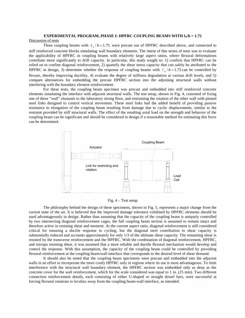
For these tests, the coupling beam specimen was precast and embedded into stiff reinforced concrete
elements simulating the interface with adjacent structural walls. The test setup, shown in Fig. 4, consisted of fixing
one of these “wall” elements to the laboratory strong floor, and restraining the rotation of the other wall with pinned
steel links designed to control vertical movement. These steel links had the added benefit of providing passive
resistance to elongation of the coupling beam resulting from damage due to cyclic displacements, similar to the
restraint provided by stiff structural walls. The effect of the resulting axial load on the strength and behavior of the
coupling beam can be significant and should be considered in design if a reasonable method for estimating this force
can be determined.
Fig. 4 – Test setup
The philosophy behind the design of these specimens, shown in Fig. 5, represents a major change from the
current state of the art. It is believed that the improved damage tolerance exhibited by HPFRC elements should be
used advantageously in design. Rather than assuming that the capacity of the coupling beam is uniquely controlled
by two intersecting diagonal reinforcement cages, the full coupling beam section is assumed to remain intact and
therefore active in resisting shear and moment. At the current aspect ratio, diagonal reinforcement is still considered
critical for ensuring a ductile response to cycling, but the diagonal steel contribution to shear capacity is
substantially reduced and accounts approximately for only 1/3 of the ultimate shear capacity. The remaining shear is
resisted by the transverse reinforcement and the HPFRC. With the combination of diagonal reinforcement, HPFRC,
and stirrups resisting shear, it was assumed that a more reliable and ductile flexural mechanism would develop and
control the response. With this assumption, the capacity of the coupling beam could be controlled by providing
flexural reinforcement at the coupling beam/wall interface that corresponds to the desired level of shear demand.
It should also be noted that the coupling beam specimens were precast and embedded into the adjacent
walls in an effort to incorporate the more costly HPFRC only in regions where its use is most advantageous. To limit
interference with the structural wall boundary element, the HPFRC section was embedded only as deep as the
concrete cover for the wall reinforcement, which for the scale considered was equal to 1 in. (25 mm). Two different
connection reinforcement details, each consisting of either U-shaped or straight dowel bars, were successful at
forcing flexural rotations to localize away from the coupling beam-wall interface, as intended.
Coupling Beam
Load
Cell
Link for restricting end
rotation
Actuator
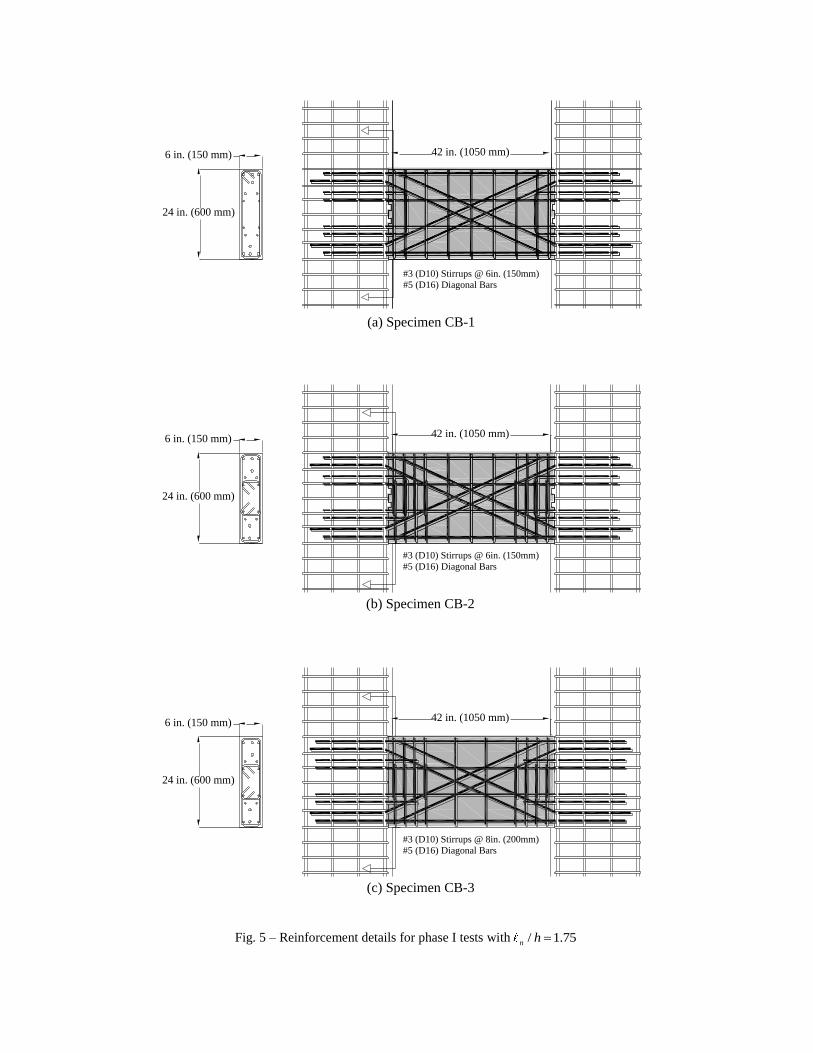
Fig. 5 – Reinforcement details for phase I tests with / 1.75n h
42 in. (1050 mm)
24 in. (600 mm)
6 in. (150 mm)
#3 (D10) Stirrups @ 6in. (150mm)
#5 (D16) Diagonal Bars
(a) Specimen CB-1
42 in. (1050 mm)
24 in. (600 mm)
6 in. (150 mm)
#3 (D10) Stirrups @ 6in. (150mm)
#5 (D16) Diagonal Bars
(b) Specimen CB-2
42 in. (1050 mm)
24 in. (600 mm)
6 in. (150 mm)
#3 (D10) Stirrups @ 8in. (200mm)
#5 (D16) Diagonal Bars
(c) Specimen CB-3
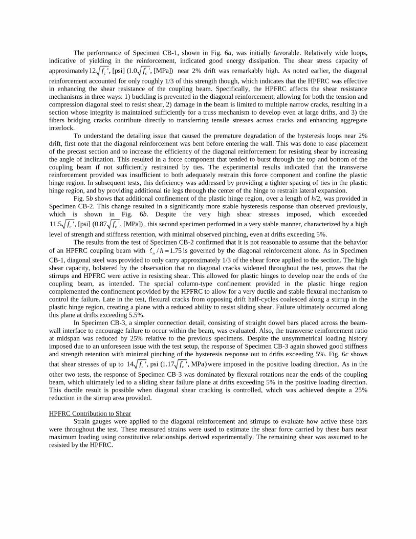
The performance of Specimen CB-1, shown in Fig. 6a, was initially favorable. Relatively wide loops,
indicative of yielding in the reinforcement, indicated good energy dissipation. The shear stress capacity of
approximately12 ', [psi] (1.0 ', [MPa])c cf f near 2% drift was remarkably high. As noted earlier, the diagonal
reinforcement accounted for only roughly 1/3 of this strength though, which indicates that the HPFRC was effective
in enhancing the shear resistance of the coupling beam. Specifically, the HPFRC affects the shear resistance
mechanisms in three ways: 1) buckling is prevented in the diagonal reinforcement, allowing for both the tension and
compression diagonal steel to resist shear, 2) damage in the beam is limited to multiple narrow cracks, resulting in a
section whose integrity is maintained sufficiently for a truss mechanism to develop even at large drifts, and 3) the
fibers bridging cracks contribute directly to transferring tensile stresses across cracks and enhancing aggregate
interlock. To understand the detailing issue that caused the premature degradation of the hysteresis loops near 2%
drift, first note that the diagonal reinforcement was bent before entering the wall. This was done to ease placement
of the precast section and to increase the efficiency of the diagonal reinforcement for resisting shear by increasing
the angle of inclination. This resulted in a force component that tended to burst through the top and bottom of the
coupling beam if not sufficiently restrained by ties. The experimental results indicated that the transverse
reinforcement provided was insufficient to both adequately restrain this force component and confine the plastic
hinge region. In subsequent tests, this deficiency was addressed by providing a tighter spacing of ties in the plastic
hinge region, and by providing additional tie legs through the center of the hinge to restrain lateral expansion.
Fig. 5b shows that additional confinement of the plastic hinge region, over a length of h/2, was provided in
Specimen CB-2. This change resulted in a significantly more stable hysteresis response than observed previously,
which is shown in Fig. 6b. Despite the very high shear stresses imposed, which exceeded
11.5 ', [psi] (0.87 ', [MPa])c cf f , this second specimen performed in a very stable manner, characterized by a high
level of strength and stiffness retention, with minimal observed pinching, even at drifts exceeding 5%.
The results from the test of Specimen CB-2 confirmed that it is not reasonable to assume that the behavior
of an HPFRC coupling beam with / 1.75n h is governed by the diagonal reinforcement alone. As in Specimen
CB-1, diagonal steel was provided to only carry approximately 1/3 of the shear force applied to the section. The high
shear capacity, bolstered by the observation that no diagonal cracks widened throughout the test, proves that the
stirrups and HPFRC were active in resisting shear. This allowed for plastic hinges to develop near the ends of the
coupling beam, as intended. The special column-type confinement provided in the plastic hinge region
complemented the confinement provided by the HPFRC to allow for a very ductile and stable flexural mechanism to
control the failure. Late in the test, flexural cracks from opposing drift half-cycles coalesced along a stirrup in the
plastic hinge region, creating a plane with a reduced ability to resist sliding shear. Failure ultimately occurred along
this plane at drifts exceeding 5.5%.
In Specimen CB-3, a simpler connection detail, consisting of straight dowel bars placed across the beam-
wall interface to encourage failure to occur within the beam, was evaluated. Also, the transverse reinforcement ratio
at midspan was reduced by 25% relative to the previous specimens. Despite the unsymmetrical loading history
imposed due to an unforeseen issue with the test setup, the response of Specimen CB-3 again showed good stiffness
and strength retention with minimal pinching of the hysteresis response out to drifts exceeding 5%. Fig. 6c shows
that shear stresses of up to 14 ', psi (1.17 ', MPa)c cf f were imposed in the positive loading direction. As in the
other two tests, the response of Specimen CB-3 was dominated by flexural rotations near the ends of the coupling
beam, which ultimately led to a sliding shear failure plane at drifts exceeding 5% in the positive loading direction.
This ductile result is possible when diagonal shear cracking is controlled, which was achieved despite a 25%
reduction in the stirrup area provided.
HPFRC Contribution to Shear
Strain gauges were applied to the diagonal reinforcement and stirrups to evaluate how active these bars
were throughout the test. These measured strains were used to estimate the shear force carried by these bars near
maximum loading using constitutive relationships derived experimentally. The remaining shear was assumed to be
resisted by the HPFRC.
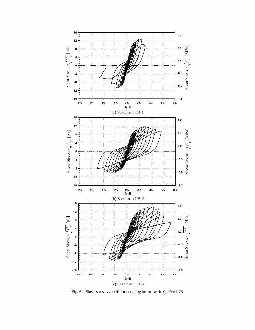
(a) Specimen CB-1
(b) Specimen CB-2
(c) Specimen CB-3
Fig. 6 – Shear stress vs. drift for coupling beams with / 1.75n h
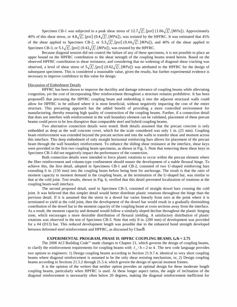
Specimen CB-1 was subjected to a peak shear stress of 12.7√𝑓𝑐′, [𝑝𝑠𝑖] (1.06√𝑓𝑐
′, [𝑀𝑃𝑎]). Approximately
40% of this shear stress, or 4.8√𝑓𝑐′, [𝑝𝑠𝑖] (0.4√𝑓𝑐
′, [𝑀𝑃𝑎]), was resisted by the HPFRC. It was estimated that 45%
of the shear applied to Specimen CB-2, or 5.3√𝑓𝑐′, [𝑝𝑠𝑖] (0.44√𝑓𝑐
′, [𝑀𝑃𝑎]), and 40% of the shear applied to
Specimen CB-3, or 5.1√𝑓𝑐′, [𝑝𝑠𝑖] (0.42√𝑓𝑐
′, [𝑀𝑃𝑎]), was resisted by the HPFRC.
Because diagonal tension did not control the failure of any of these specimens, it is not possible to place an
upper bound on the HPFRC contribution to the shear strength of the coupling beams tested herein. Based on the
observed HPFRC contribution to shear resistance, and considering that no widening of diagonal shear cracking was
observed, a level of shear stress of 5√𝑓𝑐′, [𝑝𝑠𝑖] (0.42√𝑓𝑐
′, [𝑀𝑃𝑎]) was attributed to the HPFRC for the design of
subsequent specimens. This is considered a reasonable value, given the results, but further experimental evidence is
necessary to improve confidence in this value for design.
Discussion of Embedment Details
HPFRC has been shown to improve the ductility and damage tolerance of coupling beams while alleviating
congestion, yet the cost of incorporating fiber reinforcement throughout a structure remains prohibitive. It has been
proposed5 that precasting the HPFRC coupling beam and embedding it into the adjacent structural walls could
allow for HPFRC to be utilized where it is most beneficial, without negatively impacting the cost of the entire
structure. This precasting approach has the added benefit of providing a more controlled environment for
manufacturing, thereby ensuring high quality of construction of the coupling beams. Further, if a connection detail
that does not interfere with reinforcement in the wall boundary element can be validated, placement of these precast
beams could prove to be less disruptive than comparable steel and hybrid coupling beams.
Two alternative connection details were tested. Both details assumed that the precast concrete is only
embedded as deep as the wall concrete cover, which for the scale considered was only 1 in. (25 mm). Coupling
beam reinforcement was extended beyond the precast section and into the walls to transfer shear and moment across
this interface. This deep embedment of only straight horizontal reinforcing bars allows for placement of the precast
beam through the wall boundary reinforcement. To enhance the sliding shear resistance at the interface, shear keys
were provided in the first two coupling beam specimens, as shown in Fig. 5. Note that removing these shear keys in
Specimen CB-3 did not negatively impact the performance of the connection.
Both connection details were intended to force plastic rotations to occur within the precast element where
the fiber reinforcement and column-type confinement should ensure the development of a stable flexural hinge. To
achieve this, the first detail, adopted in Specimens CB-1 and CB-2, consisted of two U-shaped reinforcing bars
extending 6 in. (150 mm) into the coupling beam before being bent for anchorage. The result is that the ratio of
moment capacity to moment demand in the coupling beam, at the termination of the U-shaped bar, was similar to
that at the cold joint. Test results, shown in Fig. 6, verified that this detail prevented localization of rotations at the
coupling beam-wall interface.
The second proposed detail, used in Specimen CB-3, consisted of straight dowel bars crossing the cold
joint. It was believed that this simpler detail would better distribute plastic rotations throughout the hinge than the
previous detail. If it is assumed that the stress in a dowel bar varies linearly from zero at the point where it is
terminated to yield at the cold joint, then the development of the dowel bar would result in a gradually diminishing
contribution of the dowel bar to the moment capacity of the coupling beam at cross sections away from the interface.
As a result, the moment capacity and demand would follow a similarly sloped decline throughout the plastic hinging
zone, which encourages a more desirable distribution of flexural yielding. A satisfactory distribution of plastic
rotations was observed in the test of Specimen CB-3. Note that only 8 in. (200 mm) of development was provided
for a #4 (D13) bar. This reduced development length was possible due to the enhanced bond strength developed
between deformed steel reinforcement and HPFRC, as discussed by Chao8.
EXPERIMENTAL PROGRAM, PHASE II: HPFRC COUPLING BEAMS, ℓn/h = 2.75
The 2008 ACI Building Code11 made changes to Chapter 21, which governs the design of coupling beams,
to clarify the reinforcement requirements for coupling beams with / 2 to 4n h . The new code language provides
two options to engineers: 1) Design coupling beams according to Section 21.9.7.4, identical to very short coupling
beams where diagonal reinforcement is assumed to be the only shear resisting mechanism, or, 2) Design coupling
beams according to Sections 21.5.2 through 21.5.4, which govern the design of special moment frames.
It is the opinion of the writers that neither option provides an optimal design for these moderate length
coupling beams, particularly when HPFRC is used. At these longer aspect ratios, the angle of inclination of the
diagonal reinforcement is necessarily often below 20 degrees, making the diagonal reinforcement inefficient for
resisting shear. As a result, an impractically large area of confined diagonal reinforcement is required for coupling
beams expected to resist high shears. If the second alternative is selected, there is no provision for including a
moderate amount of diagonal reinforcement, which has the effect of preventing a sliding shear failure and improving
coupling beam ductility when subjected to high shear stress reversals. These observations are particularly pertinent
to the design of HPFRC coupling beams, where the HPFRC resists a significant amount of the applied shear.
To offer engineers an alternative design option for coupling beams with / 2 to 4n h , two precast HPFRC
coupling beams with an aspect ratio of 2.75 were tested under displacement reversals. To accommodate these longer
beams without reducing the cross section size, the test setup shown in Fig. 4 was modified with extensions to the
steel links.
Based on the results from the Phase I tests described above, the following revised design philosophy for
HPFRC coupling beams was adopted for the design of the coupling beams with longer aspect ratios. 1) Assume that diagonal reinforcement provides approximately 30-40% of the required shear strength (Vn),
and select appropriate diagonal bar orientation angle and bar sizes.
2) The contribution of the diagonals to moment strength is now known. Assuming that the HPFRC carries
roughly 15% of the total moment strength, select flexural reinforcement (As) to provide the remaining
design flexural strength.
3) Place a reasonable fraction of this longitudinal flexural reinforcement as dowel bars to ensure that failure
will not localize at the interface with the wall.
-In the tests presented herein, “reasonable fraction” corresponds to:
-30-40% of As for coupling beams with an aspect ratio less than 2
-15-20% of As for longer coupling beams
4) Shear design: consider the contribution of the diagonal reinforcement selected in Step 1 to Vn; then provide
30-40% of Vn through transverse reinforcement, and attribute the remainder to the HPFRC. Verify that the
shear carried by the HPFRC does not exceed 5 ' , [psi] (0.42 ' , [MPa])c cf f .
5) Provide column-type confinement to the ends of the coupling beam, extending approximately h/2 away
from the face of the walls. No special confinement is required in addition to the confinement provided by
the HPFRC for the remaining portion of the span.
6) Through a moment-curvature analysis, check that (and modify flexural design if required):
un
MM
-For this moment-curvature analysis, the constitutive model selected for the HPFRC has an
important impact on the validity of the results. In this study, the constitutive models shown in Figs. 2 and 3
were used for analysis.
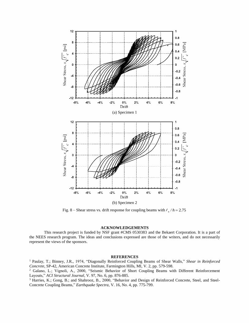
The reinforcement provided for the two specimens tested in this series is shown in Fig. 7. The expected
shear stress for these beams was 10 ', [psi] (0.83 ', [MPa])c cf f and 7.1 ', [psi] (0.59 ', [MPa])c cf f ,
respectively. The shear stress versus drift responses for both of these specimens, shown in Fig. 8, demonstrate good
agreement with the predicted capacities. In addition, the excellent ductility, wide hysteresis loops, and good stiffness
retention typical of previous HPFRC coupling beam tests were again observed. It should be noted that both
specimens exhibited this response to drift levels exceeding 5% in both loading directions. Finally, the simplified
connection detail utilizing dowel bars was effective at transferring the shear and moment between the precast
HPFRC section and the wall and ensuring that plastic rotations do not localize at the beam-wall interface. This was
all achieved without disrupting the wall boundary element reinforcement.
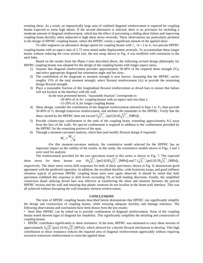
CONCLUSIONS
The tests of HPFRC coupling beams described herein demonstrate that HPFRC can significantly simplify
the design and construction of coupling beams, while ensuring adequate ductility and damage tolerance. The
following observations and conclusions have been drawn from the test results:
• Steel fiber HPFRC can be relied on to provide confinement of diagonal reinforcement. None of the coupling
beams tested showed signs of diagonal bar instability. This significantly simplifies the detailing and construction of
coupling beams.
• HPFRC contributes significantly to shear resistance. In the tests, HPFRC was estimated to carry shear stresses of
approximately 5√𝑓𝑐′, [𝑝𝑠𝑖] (0.42√𝑓𝑐
′, [𝑀𝑃𝑎]), which allowed for a ductile flexural mechanism to develop. This high
contribution to shear resistance reduces the required area of diagonal reinforcement appreciably without requiring
excessive transverse reinforcement to resist the applied shear.
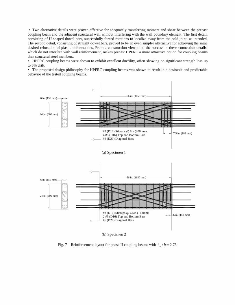
• Two alternative details were proven effective for adequately transferring moment and shear between the precast
coupling beam and the adjacent structural wall without interfering with the wall boundary element. The first detail,
consisting of U-shaped dowel bars, successfully forced rotations to localize away from the cold joint, as intended.
The second detail, consisting of straight dowel bars, proved to be an even simpler alternative for achieving the same
desired relocation of plastic deformations. From a construction viewpoint, the success of these connection details,
which do not interfere with wall reinforcement, makes precast HPFRC a more attractive option for coupling beams
than structural steel members.
• HPFRC coupling beams were shown to exhibit excellent ductility, often showing no significant strength loss up
to 5% drift.
• The proposed design philosophy for HPFRC coupling beams was shown to result in a desirable and predictable
behavior of the tested coupling beams.
Fig. 7 – Reinforcement layout for phase II coupling beams with / 2.75n h
66 in. (1650 mm)6 in. (150 mm)
24 in. (600 mm)
#3 (D10) Stirrups @ 8in (200mm)
4 #5 (D16) Top and Bottom Bars
#6 (D20) Diagonal Bars
66 in. (1650 mm)6 in. (150 mm)
24 in. (600 mm)
#3 (D10) Stirrups @ 6.5in (163mm)
2 #5 (D16) Top and Bottom Bars
#6 (D20) Diagonal Bars
6 in. (150 mm)
7.5 in. (188 mm)
(a) Specimen 1
(b) Specimen 2
(a) Specimen 1
(b) Specimen 2
Fig. 8 – Shear stress vs. drift response for coupling beams with / 2.75n h
ACKNOWLEDGEMENTS
This research project is funded by NSF grant #CMS 0530383 and the Bekaert Corporation. It is a part of
the NEES research program. The ideas and conclusions expressed are those of the writers, and do not necessarily
represent the views of the sponsors.
REFERENCES
1 Paulay, T.; Binney, J.R., 1974, “Diagonally Reinforced Coupling Beams of Shear Walls,” Shear in Reinforced
Concrete, SP-42, American Concrete Institute, Farmington Hills, MI, V. 2, pp. 579-598. 2 Galano, L.; Vignoli, A., 2000, “Seismic Behavior of Short Coupling Beams with Different Reinforcement
Layouts,” ACI Structural Journal, V. 97, No. 6, pp. 876-885. 3 Harries, K.; Gong, B.; and Shahrooz, B., 2000, “Behavior and Design of Reinforced Concrete, Steel, and Steel-
Concrete Coupling Beams,” Earthquake Spectra, V. 16, No. 4, pp. 775-799.
4 Tassios, T.; Moretti, M.; and Bezas, A., 1996, “On the Behavior and Ductility of Reinforced Concrete Coupling
Beams of Shear Walls,” ACI Structural Journal, V. 93, No. 6, pp. 711-720. 5 Canbolat, B.A.; Parra-Montesinos, G.; and Wight, J., 2005, “Experimental Study on Seismic Behavior of High-
Performance Fiber-Reinforced Cement Composite Coupling Beams,” ACI Structural Journal, V. 102, No. 1, pp.
159-166. 6 Canbolat, B.A., 2004, “Seismic Behavior of High-Performance Fiber Reinforced Cementitious Composite
Coupling Beams,” Ph.D. Dissertation, Report No. UMCEE 04-11, University of Michigan, Ann Arbor, MI, 193 pp. 7 Parra-Montesinos, G.J., 2005, “High-Performance Fiber-Reinforced Cement Composites: An Alternative for
Seismic Design of Structures,” ACI Structural Journal, V. 102, No. 5, pp. 668-675. 8 Chao, S.H., 2005, “Bond Characterization of Reinforcing Bars and Prestressing Strands in High Performance Fiber
Reinforced Cementitious Composites Under Monotonic and Cyclic Loading,” Ph.D. Dissertation, University of
Michigan, Ann Arbor, MI, 475 pp. 9 Paulay, T., 1971, “Coupling Beams of Reinforced Concrete Shear Walls,” Journal of the Structural Division,
Proceedings of the American Society of Civil Engineers, V. 97, No. ST3, pp. 843-862. 10 Luisoni, C.J.; Somenson, H.M.; Ungaro, M.A., 1970, “Verification Experimental de un Calculo Plastico y Otro
Elastico do una Patrad de Corte,” XIV Jornades Sudamericanas de Ingerieri a Estructural: y IV Simposio
Panamericano de Estructuras, pp. 230-286. 11 ACI Committee 318, 2008, “Building Code Requirements for Structural Concrete (ACI 318-08) and
Commentary,” American Concrete Institute, Farmington Hills, MI, 465 pp. 12 Harries, K. A.; Fortney, P. J.; Shahrooz, B. M.; Brienen, P. J., 2005, “Practical Design of Diagonally Reinforced
Concrete Coupling Beams – Critical Review of ACI 318 Requirements,” ACI Structural Journal, V. 102, No. 6, pp.
876-882. 13 Liao, W.C.; Chao, S.H.; Park, S.Y.; and Naaman, A.E., 2006, “Self-Consolidating High Performance Fiber
Reinforced Concrete (SCHPFRC) – Preliminary Investigation,” Technical Report No. UMCEE 06-02, University of
Michigan, Ann Arbor, MI, 68 pp. 14 ASTM C 1609/C 1609M – 05, “Standard Test Method for Flexural Performance of Fiber-Reinforced Concrete
(Using Beam With Third-Point Loading),” West Conshohcken, PA., 2005.