2. detailing of beams (for class held on 5 march...
TRANSCRIPT

1
2. DETAILING OF BEAMS(For class held on 5th March 07)
By Dr. G.S.Suresh, Professor, Civil Engineering Department, NIE, Mysore(Ph:9342188467, email: gss_nie@ yahoo.com)2.1 Introduction:
Beams are structural elements carrying transverse external loads that cause bendingmoment, shear forces and in some cases torsion across their length. Concrete is strongin compression and very weak in tension. Steel reinforcement is used to take uptensile stresses in reinforced concrete beams. Mild steel bars of round section wereused in RCC work. But with the introduction of deformed and twisted bars, the use ofmild steel bars had declined. Deformed or High yield strength deformed bars (HYSD)have ribs on the surface and this increases the bond strength at least by 40%compared to that of mild steel bar. Fig. 2.1 shows mild steel and deformed steel bars.
To facilitate construction process, good detailing of reinforcements with properdrawings are essential at the site of construction. These drawing generally alsoinclude a bar bending schedule. The bar bending schedule describes the length andnumber, position and the shape of the bar. The detailing is normally associated withi) Size and number (or spacing) of bars, ii) Lap and curtailment (or bending) of bars,iii) Development length of bars, iv) Clear cover to the reinforcement and v) spacerand chair bars.
Anchorage in steel bars is normally provided in the form of bends and hooks. Twistedsteel bars or deformed steel bars are not provided with hooks. The anchorage value ofbend of bar is taken as 4 times the diameter of bar for every 450 bend subjected tomaximum of 16 times the diameter of bar. Fig.2.2 shows the standard hooks andbends. Bars are lapped over each other for increasing the length of bars. Minimum laplength should be equal to development length. Development length for bars indifferent concrete mix is given tables 4.2 to 4.4 of SP34.
Fig. 2.1

2
The beams are classified as:i) According to shape: Rectangular, T, L, Circular etcii)According to supporting conditions: Simply supported, fixed, continuous and
cantilever beamsiii) According to reinforcement: Singly reinforced and doubly reinforced
Depth of the beam is determined based on flexural strength and to satisfy the deflectioncriteria. Generally the ratio of span to depth ratio is kept as 10 to 15 and the depth towidth ratio of rectangular be is taken in the range of 1.5 to 2.
Minimum cover in beams must be 25 mm or shall not be less than the larger diameter ofbar for all steel reinforcement including links. Nominal cover specified in Table 16 and16A of IS456-2000 should be used to satisfy the durability criteria.
Generally a beam consists of following steel reinforcements:i) Longitudinal reinforcement at tension and compression face (Min of two 12 mm
diameter bar is required to be provided in tension) in single or multiple rows areprovided.
ii)Shear reinforcements in the form of vertical stirrups and or bent up longitudinalbars are provided. ( The bar bent round the tensile reinforcement and taken into thecompression zone of an RCC beams are called stirrups)
iii) Side face reinforcement in the web of the beam is provided when the depth of theweb in a beam exceeds 750 mm. (0.1% of the web area and shall be distributedequally on two faces at a spacing not exceeding 300 mm or web thicknesswhichever is less)
Arrangements of bars in a beam should confirm to the requirements of clause given in 8.1and 8.2 of SP34. Bars of size 6,8,10,12,16,20,25,32,50 mm are available in market. Fig.2.3 shows different types bars used in a beam.
Fig.2.2

3
While drawing the details of a beam following convention representation of bars are usedMild steel bars : ; HYSD bars: # orMain bars are shown by thick single line.Hanger bars are shown by medium thick lines.Stirrups are shown by dotted or thin line. Different types of stirrups used are shown inFig. 2.4.
Maximum spacing of stirrup should be 0.75d or 300mm whichever is less and d or 300mm whichever is less, where d is diameter of main bar. Diameter of stirrups varies from6mm to 12mm.Bar bending schedule should include shape of bar, number of bars used, length andweight. A standard form of bar bending schedule table is shown below
Fig. 2.3
Fig. 2.4

4
Format for Bar bending scheduleSl.No. Type of bar
and markShape No. Length in
meterWeight perunit lengthin Kg
Weightin Kg
Area and weight of different bars are given in the table 2.1
Table 2.1 Standard sizes and weight of round barsDiameter in mm Sectional Area in
mm2Weight per meter in Kg ( N)
6 28 0.22 (2.2)8 50 0.39 (3.9)10 78.5 0.62 (6.2)12 113 0.89 (8.9)16 201 1.08 (10.8)20 314 2.47 (24.7)25 490 3.85 (38.5)
Generally beams are represented by longitudinal section and cross-section at importantpoints. A typical beam drawing of a simply supported beam is shown in Fig.
Fig. 2.5 Detailing of a simply supported beam

5
Problems:1.SIMPLY SUPPORTED RECTANGULAR BEAMSI) Draw the Longitudinal section, cross section and prepare bar bending schedule of a
rectangular simply supported RCC beam with the following data:Clear span =3.5mWidth of beam = 220mmOverall depth of beam = 300mmBearing width in support = 200 mmMain reinforcement = 5 Nos -12 mm diameter bars with 2 bars bent up at L/7 fromcentre of supportAnchor/hanger bars= 2-10 mm diameterStirrups = 6 mm diameter @ 200 mm c/c.Materials : Mild steel, M20 grade concrete
Solution:i) Longitudinal and Cross-Section:
Fig. 2.6 Detailing of a simply supported beam

6
ii) Bar Bending Schedule:a) Bottom straight bar (12 dia)= Total length of beam +2 x16 -2 x 3 -2 x end cover
= (3500+2 x 200)+26 x 12-2 x 25 =41624200 mm
b) Length of bent up bar (12 dia)= Length of straight bar +2 x (0.42 x depth of bend)=4162+2 x 0.42 x 250 =43724400 mm
c) Length of hanger bar (10 dia)= Length of straight bar =41624200 mm
d) Stirrups:
Number of stirrups = Length of bar (end to end)/c/c distance of stirrup= [(3500+2x200)-2x25]/200 = 17
Length of stirrup = 2 ( A+B)+24 of stirrup= 2x(250+170)+24 x 6 = 984 mm 1000 mm
Bar bending schedule is given below:
II) Draw the Longitudinal section, cross section and prepare bar bending schedule of arectangular simply supported RCC beam with the following data:Clear span =4.5mWidth of beam = 250mmOverall depth of beam = 300mmMain reinforcement = 5 Nos -18 mm diameter bars with 2 bars bent up at 900mmfrom inside of each end supportAnchor/hanger bars= 2-12 mm diameterStirrups = 6 mm diameter @ 200 mm c/c.Concrete cover = 25 mmMaterials : HYSD bars, M20 grade concrete

7
Solution:i) Longitudinal and Cross-Section:
ii) Bar Bending Schedule:a) Bottom straight bar (18 dia)= Total length of beam -2 x end cover
= (4500+2 x 200) -2 x 25 =4850 mm
b) Length of bent up bar (18 dia)= Length of straight bar +2 x (0.42 x depth of bend)=4850+2 x 0.42 x 250 =5050 mm
c) Length of hanger bar (12 dia)= Length of straight bar =4850 mm
d) Stirrups:
Number of stirrups = Length of bar (end to end)/c/c distance of stirrup= [(4500+2x200)-2x25]/200 = 24.25 25
Length of stirrup = 2 ( A+B)+24 of stirrup= 2x(250+200)+24 x 6 = 1044 mm 1100 mm
Bar bending schedule is given below:

8
2. CONTINUOUS RECTANGULAR BEAMSI) Draw the Longitudinal section and two cross sections one near the support and other
near the mid span of a RCC continuous beam with the following data:Clear span of beams = 3m eachWidth of beam = 200mmOverall depth of beam = 300mmWidth in intermediate supports = 200 mmMain reinforcement = 4 Nos -12 mm diameter bars with 2 bars bent upAnchor/hanger bars= 2-10 mm diameterStirrups = 6 mm diameter @ 300 mm c/c.Materials : HYSD bars and M20 grade concrete
Solution:

9
II) A rectangular beam of cross section 300 x 450 mm is supported on 4 columnswhich are equally spaced at 3m c/c. The columns are of 300 mm x 300 mm in section.The reinforcement consists of 4 bars of a6 mm diameter (+ve reinforcement) at midspan and 4 bars of 16 mm diameter at all supports (-ve reinforcement). Anchor barsconsists of a 2-16 mm diameter. Stirrups are of 8 mm diameter 2 legged vertical at 200c/c throughout. Grade of concrete is M20 and type of steel is Fe 415. Draw longitudinalsection and important cross sections.
Solution:

10
3.CANTILEVER BEAMSI) Draw to scale of 1:20 the Longitudinal section and two cross-section of a
cantilever beam projecting 3.2 from a support using following dataClear span =3.2mOverall depth at free end = 150 mmOverall depth at fixed end = 450 mmWidth of cantilever beam = 300 mmMain steel = 4-28 mm dia with two bars curtailed at 1.5m from
supportAnchor bars = 2 Nos. 16 mm diaNominal stirrups = 6mm dia at 40 mm c/cBearing at fixed end = 300 mmUse M20 concrete and Fe 415 steel
Solution:

11
II) A cantilever beam with 3.2m length is resting over a masonry wall and supportinga slab over it. Draw to a suitable scale Longitudinal section, two cross-sectionsand sectional plan with the following data:Size of beam = 300 mm x 350 mm at free end and 300 mm x 450 mm at fixed endand in the wall up to a length of 4.8mMain steel: 4 nos. of 25 mm dia bars, two bars curtailed at 1.2m from free endHanger bars: 2 nos. 16mm.Stirrups: 6mm dia 2 legged stirrups @ 200 mm c/c the support length and @100mm c/c from fixed end up to length of 1m @ 150mm c/c up to curtailed bars andremaining @ 200 c/c.Use M20 concrete and Fe 415 steel
Solution:

12
4.FLANGED BEAMSA beam has following data
Clear span = 4mSupport width = 300mmSize of web = 350 x 400Size of flange = 1200 x 120mmMain reinforcement in two layers : 3-20 tor + 3-16 tor and to be curtailed at adistance 400 mm from inner face of supportHanger bars: 3- 20 torStirrups: 2L-8 tor @ 200 c/cUse M20 concrete and Fe 415 steel
Draw longitudinal and cross section if the beam isi) T-beamii) Inverted T-beamiii) L-Beam
Solution:
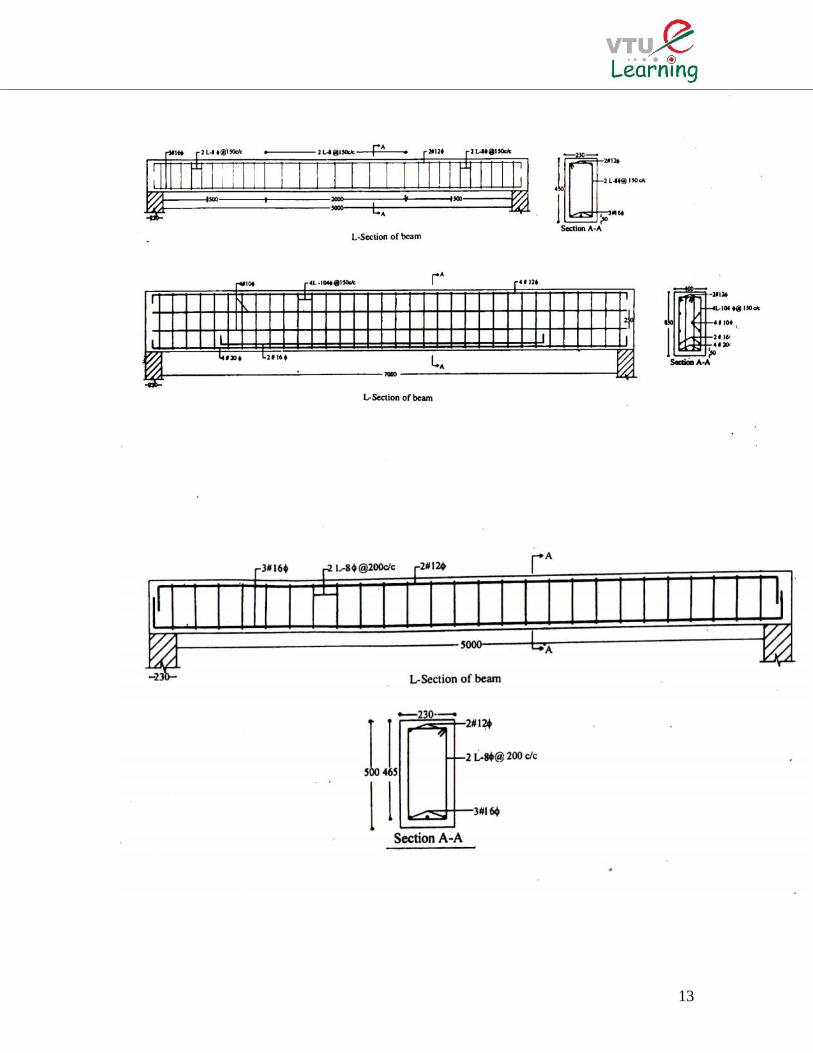
Standard RCC drawings with various data are presented in the figures to follow
13

14