ew resistant coupling beams
TRANSCRIPT

8/12/2019 EW Resistant Coupling Beams
http://slidepdf.com/reader/full/ew-resistant-coupling-beams 1/5
36 DECEMBER 2010/ C cre e er
BY GUSTAVO J. PARRA-MONTESINOS, JAMES K. WIGHT, AND MONTHIAN SETKIT
E r q ke-ReC Be DRe rce e
Strain-hardening fiber-reinforced concrete provides means to simplify detailing
F or some time, there has been an inherent challenge inthe design and construction of coupling beams in
earthquake-resistant coupled wall systems. The failure ofcoupling beams with traditional longitudinal and transversereinforcement during the 1964 Alaska earthquake indicatedthe need for new designs that would allow these beamsto sustain large shear reversals without a substantialdegradation of strength and stiffness. Experimentalresearch conducted in New Zealand showed that the useof well-confined diagonal reinforcement cages—designedto resist the total shear demand—ensures stablebehavior under displacement reversals such as thoseinduced during a strong earthquake. 1 Current designprovisions in the ACI 318-08 Building Code 2 are largelybased on this research.
The reliance on diagonal reinforcement to resist theentire coupling beam shear demand, however, oftentranslates into the use of large diameter diagonal bars—for example, No. 11 (No. 35) or larger—that require longdevelopment lengths and are difficult to handle on site.The construction of coupling beams is further complicatedby the need for column-type transverse reinforcement toconfine each diagonal reinforcement cage or the entirebeam to maintain the integrity of the concrete and preventpremature buckling of the diagonal bars. Figure 1 showsa typical design of a coupling beam in an earthquake-
prone region.
In recent years, the use of relatively slender couplingbeams (that is, beams with span-to-overall-depth ratios[aspect ratios] on the order of 3) has become populardue to limitations in story heights. In these beams,however, the effectiveness of diagonal reinforcement toresist shear significantly decreases because of the
shallow angle with the beam longitudinal axis (less than
Fig. 1: Typical diagonally reinforced coupling beam (photo courtesyof Rémy Lequesne)

8/12/2019 EW Resistant Coupling Beams
http://slidepdf.com/reader/full/ew-resistant-coupling-beams 2/5

8/12/2019 EW Resistant Coupling Beams
http://slidepdf.com/reader/full/ew-resistant-coupling-beams 3/5
38 DECEMBER 2010/ C cre e er
such that the shear corresponding to the expectedmoment capacity being reached at both ends of thecoupling beam would be close to the upper limit inACI 318-082 (10 √ f c
′ psi [0.83 √ f c′ MPa]). The expected beam
flexural capacity was calculated considering overstrengthand strain-hardening of the steel but neglecting thecontribution of fiber-reinforced concrete in tension.Assuming that the HPFRC provides a shear resistanceof 5 √ f c
′ psi (0.42 √ f c′ MPa), based on previous work, 5
transverse reinforcement was designed to resist theremaining shear demand. Because large inelastic rotationswere expected at the beam ends, it was decided to providecolumn-type confinement over a distance of half thebeam depth from the wall faces; this reinforcement wasgreater than that required for shear strength purposes.The transverse reinforcement outside of the plastic hingeregion consisted of two-legged single stirrups.
We envisioned the use of a precast coupling beamdesign. This would allow the use of regular concrete inthe structural walls and speed up the construction of thecoupled wall system. Interference with wall reinforcementwas prevented by extending the precast portion of thebeam only into the wall cover. Moment transfer at theconnection between the precast coupling beam and thecast-in-place walls was to be achieved by extending theflexural reinforcement a full development length beyond
the precast portion. Also, to prevent excessive inelasticdeformations at the precast coupling beam-wall interface,intermediate U-shaped reinforcement was provided,which extended approximately 8 in. (200 mm) into thespan (Fig. 2).
Figure 3 is a schematic of the test setup. As shown inFig. 3, the beam was rotated 90 degrees for testingconvenience. The coupling beams were loaded to inducedouble curvature. For this purpose, lateral displacementswere applied to the top block, which was prevented fromrotating by two steel links. These links also providedsome axial restraint to the coupling beams to simulatethe restraint provided by structural walls in an actualcoupled wall system. The specimens were subjected tolateral drift cycles of increasing magnitude until thebeams exhibited substantial strength degradation.
matERialsBased on previous research, 5 concrete reinforced
with a 1.5% volume fraction of high-strength hooked-steel fibers was selected for use in the coupling beams.Concrete proportions by weight were as follows: 1.2(Type III cement): 0.3 (fly ash): 0.6 (water): 1.7 (sand):1.0 (coarse aggregate): 0.01 (high-range water-reducingadmixture): 0.0095 (viscosity-modifying admixture). Coarseaggregate consisted of crushed limestone with a maximum
size of 1/2 in. (13 mm). Commerciallyavailable hooked-steel fibers wereused. These fibers were 1.2 in. (30 mm)long and 0.015 in. (0.38 mm) indiameter, made of a wire with aspecified tensile strength of 330 ksi(2300 MPa). The concrete mixturewas designed such that a highlyworkable composite with acompressive strength of about10,000 psi (70 MPa) would be obtained.Results from 4 x 8 in. (100 x 200 mm)cylinder tests, as well as from ASTM1609-06 four-point bending tests onbeams with a 6 in. (150 mm) square
cross section and 18 in. (450 mm)span, are shown in Table 1.
All reinforcing bars were Grade 60(420) steel. The yield and ultimatestrengths for the various reinforcingbars are shown in Table 2.
BEhavioR of hpfRCCoupling BEams with-out Diagonal BaRs
Figure 4 shows the average shearstress versus drift response for the
two test coupling beams. Drift is
T ABLE 1:
COMPRESSIVE AND FLEXURAL STRENGTH OF FIBER - REINFORCED CONCRETE
Specimennumber
(aspect ratio) f
c ′,
ksi (MPa) f
p 1,*
psi (MPa) f 150 , 0.75 ,*
psi (MPa) f 150 , 3.0,
*
psi (MPa)
1 (3.3) 9.9 (68) 1000 (6.9) 1080 (7.4) 650 (4.5)
2 (2.75) 9.8 (68) 1030 (7.1) 1280 (8.8) 980 (6.8)*Obtained using a four-point bending test per ASTM 1609-06; f p1 is first peak flexuralstrength; f 150, 0.75 is equivalent flexural strength at 0.03 in. (0.75 mm) deflection; f 150, 3.0 isequivalent flexural strength at 0.12 in. (3.0 mm) deflection.
T ABLE 2:P ROPERTIES OF REINFORCING BARS
Specimen number(aspect ratio)
Bar size,No.
Yield strength f y, ksi (MPa)
Tensile strength f u, ksi (MPa)
1 (3.3)
6 (19) 79 (544) 100 (689)
4 (13) 77 (531) 96 (661)
2 (2.75)
6 (19) 76 (524) 94 (648)
5 (16) 64 (441) 97 (668)
4 (13) 85 (586) 101 (696)
8/12/2019 EW Resistant Coupling Beams
http://slidepdf.com/reader/full/ew-resistant-coupling-beams 4/5
C cre e er / DECEMBER 2010 39
Load cell
Coupling beamActuator
Reaction wall
Strong oor
Link for restrictingend rotation
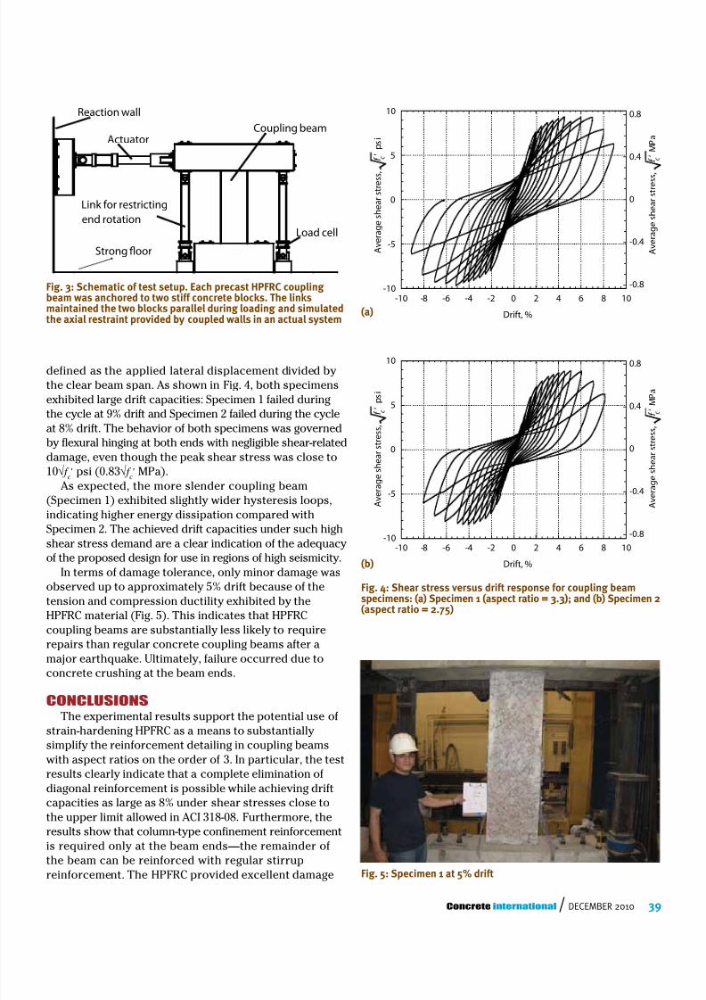
Fig. 3: Schematic of test setup. Each precast HPFRC couplingbeam was anchored to two stiff concrete blocks. The linksmaintained the two blocks parallel during loading and simulatedthe axial restraint provided by coupled walls in an actual system
defined as the applied lateral displacement divided bythe clear beam span. As shown in Fig. 4, both specimensexhibited large drift capacities: Specimen 1 failed duringthe cycle at 9% drift and Specimen 2 failed during the cycleat 8% drift. The behavior of both specimens was governedby flexural hinging at both ends with negligible shear-relateddamage, even though the peak shear stress was close to10√ f c
′ psi (0.83 √ f c′ MPa).
As expected, the more slender coupling beam(Specimen 1) exhibited slightly wider hysteresis loops,indicating higher energy dissipation compared withSpecimen 2. The achieved drift capacities under such highshear stress demand are a clear indication of the adequacyof the proposed design for use in regions of high seismicity.
In terms of damage tolerance, only minor damage wasobserved up to approximately 5% drift because of thetension and compression ductility exhibited by theHPFRC material (Fig. 5). This indicates that HPFRCcoupling beams are substantially less likely to requirerepairs than regular concrete coupling beams after amajor earthquake. Ultimately, failure occurred due toconcrete crushing at the beam ends.
ConClusionsThe experimental results support the potential use of
strain-hardening HPFRC as a means to substantiallysimplify the reinforcement detailing in coupling beamswith aspect ratios on the order of 3. In particular, the testresults clearly indicate that a complete elimination ofdiagonal reinforcement is possible while achieving driftcapacities as large as 8% under shear stresses close tothe upper limit allowed in ACI 318-08. Furthermore, theresults show that column-type confinement reinforcementis required only at the beam ends—the remainder ofthe beam can be reinforced with regular stirrup
reinforcement. The HPFRC provided excellent damage
-10
-5
0
5
10
-10 -8 -6 -4 -2 0 2 4 6 8 10
-0.8
-0.4
0
0.4
0.8
A v e r a g e s h e a r s t r e s s
,
f c '
i s p
Drift, %
a P M
-10
-5
0
5
10
-10 -8 -6 -4 -2 0 2 4 6 8 10
-0.8
-0.4
0
0.4
0.8
Drift, %
A v e r a g e s h e a r s t r e s s
,
f c '
A v e r a g e s h e a r s t r e s s ,
f c '
i s p
a P M
A v e r a g e s h e a r s t r e s s ,
f c '
Fig. 4: Shear stress versus drift response for coupling beamspecimens: (a) Specimen 1 (aspect ratio = 3.3); and (b) Specimen 2(aspect ratio = 2.75)
(a)
(b)
Fig. 5: Specimen 1 at 5% drift

8/12/2019 EW Resistant Coupling Beams
http://slidepdf.com/reader/full/ew-resistant-coupling-beams 5/5