detailed project report (dpr) integrated command and ... · detailed project report for jalandhar...
TRANSCRIPT

Detailed Project Report (DPR) Integrated Command and Control Centre
Project Management Consultants for
Jalandhar Smart City Limited

Detailed Project Report for Jalandhar Integrated Smart Solutions
1 | P A G E
Disclaimer
This report is based on our assessment of data & information collected from or provided by various
government departments, officials, websites as on date and our expertise & past experience and is
accordingly, given for the specific purpose of internal use by Jalandhar Smart city Limited. Any
observation or data if not entirely correct or accurate, should be communicated to us immediately, as
the inaccuracy or incompleteness could have a material impact on our conclusions. We have taken
reasonable steps to ensure that the data obtained from reliable sources and this report is accurate and
authoritative in all respects however, there can be no assurance that the authorities or regulators may
not take a position contrary to our conclusions.
This report is for sole information of Jalandhar Smart city Limited and we accept no responsibility to
any other party.
Detailed Project Report for Jalandhar Integrated Smart Solutions
2 | P A G E
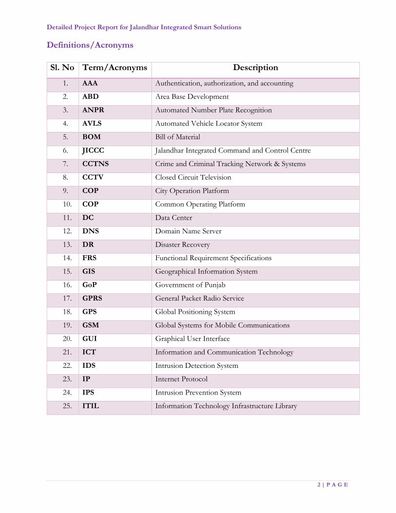
Definitions/Acronyms
Sl. No Term/Acronyms Description
1. AAA Authentication, authorization, and accounting
2. ABD Area Base Development
3. ANPR Automated Number Plate Recognition
4. AVLS Automated Vehicle Locator System
5. BOM Bill of Material
6. JICCC Jalandhar Integrated Command and Control Centre
7. CCTNS Crime and Criminal Tracking Network & Systems
8. CCTV Closed Circuit Television
9. COP City Operation Platform
10. COP Common Operating Platform
11. DC Data Center
12. DNS Domain Name Server
13. DR Disaster Recovery
14. FRS Functional Requirement Specifications
15. GIS Geographical Information System
16. GoP Government of Punjab
17. GPRS General Packet Radio Service
18. GPS Global Positioning System
19. GSM Global Systems for Mobile Communications
20. GUI Graphical User Interface
21. ICT Information and Communication Technology
22. IDS Intrusion Detection System
23. IP Internet Protocol
24. IPS Intrusion Prevention System
25. ITIL Information Technology Infrastructure Library

Detailed Project Report for Jalandhar Integrated Smart Solutions
3 | P A G E
26. JSCL Jalandhar Smart City Limited
27. LAN Local Area Network
28. LED Light Emitting Diode
29. MCJ Municipal Corporation Jalandhar
30. O&M Operations & Maintenance
31. OEM Original Equipment Manufacturer
32. OFC Optical Fibre Cable
33. OS Operating Systems
34. OTP One Time Password
35. PA System Public Address System
36. PDU's Power Distribution Units
37. PoE/ PoE+ Power over Ethernet
38. PoP Points of Presence
39. PTZ Pan Tilt Zoom
40. QR Code Quick Response Code
41. RF Radio Frequency
42. RFID Radio Frequency Identification
43. RLVD Red Light Violation Detection
44. RoW Right of Way
45. RPO Recovery Point Objective
46. RTO Recovery Time Objective
47. MSI Master System Integrator
48. SLA Service Level Agreement
49. SNMP Simple Network Management Protocol
50. SMPS Switched Mode Power Supply
51. SOP Standard Operating Procedure
52. UPS Uninterruptible Power Supply
53. VaMS Variable Message System

Detailed Project Report for Jalandhar Integrated Smart Solutions
4 | P A G E
54. VLAN Virtual Local Area Network
55. VMS Video Management Software/System
56. WAN Wide Area Network

Detailed Project Report for Jalandhar Integrated Smart Solutions
5 | P A G E
Table of Contents
Preface Error! Bookmark not defined.
Project Background 10
1. Introduction 13
1.1. About Jalandhar 14
1.2. Jalandhar Smart City Limited (JSCL) 15
1.3. Vision Statement for Jalandhar Smart City and Associated Objectives 15
1.4. Project Structure 16
1.5. Stakeholder in Jalandhar Smart City Project 17
1.6. Surveys 17
2. Feasibility Study Assessment 21
2.1. Assessment Processes 21
2.2. Study Parameters 21
2.3. Envisaged Smart Solution 22
2.4. Impact Assessment 23
2.5. Envisaged Outcome of ICT Solution 23
3. Our Approach 26
3.1. Pre –Implementation Phase 26
3.2. Implementation Phase 27
3.3. Post Implementation Phase 28
4. Integrated ICT Components 30
5. Project Undertakings 32
5.1. Team Mobilization, Project Planning & Management/ Maintenance Management 33

Detailed Project Report for Jalandhar Integrated Smart Solutions
6 | P A G E
5.2. Survey and Detailed Design of all Smart Solutions Components 33
5.3. Prototype Acceptance and Factory Acceptance Testing 35
5.4. Hardware Supply and Installation Stage 36
5.5. Software Development 36
5.6. System Study, Design, Development, Integration, Testing and Certification 37
5.7. System Integration 40
5.8. Testing 40
5.9. Third Party Acceptance Testing, Audit and Certification 43
5.10. Capacity building & Training 46
5.11. Change Management 50
5.12. Final Deployment and Documentation 51
5.13. Operational System Acceptance 53
5.14. Comprehensive Maintenance for System and Services 54
5.15. Support Staff Required 56
6. Roles and Responsibilities 59
7. Scope of Project 66
7.1. Jalandhar Integrated Command Control Centre (JICCC) 67
7.1.1. Various Components of JICCC 68
7.1.2. General Requirements 72
7.1.3. Key Performance Indicators 72
7.1.4. Product Licenses 75
7.1.5. Site Preparation for JICCC including Data Center 76
7.1.6. Functional requirements 78
7.2. Data Center (DC) & Disaster Recovery (DR) 153
7.2.1. Functional Requirements – Data Center & Disaster Recovery 154
7.3. .2 Network Backbone 209
Detailed Project Report for Jalandhar Integrated Smart Solutions
7 | P A G E
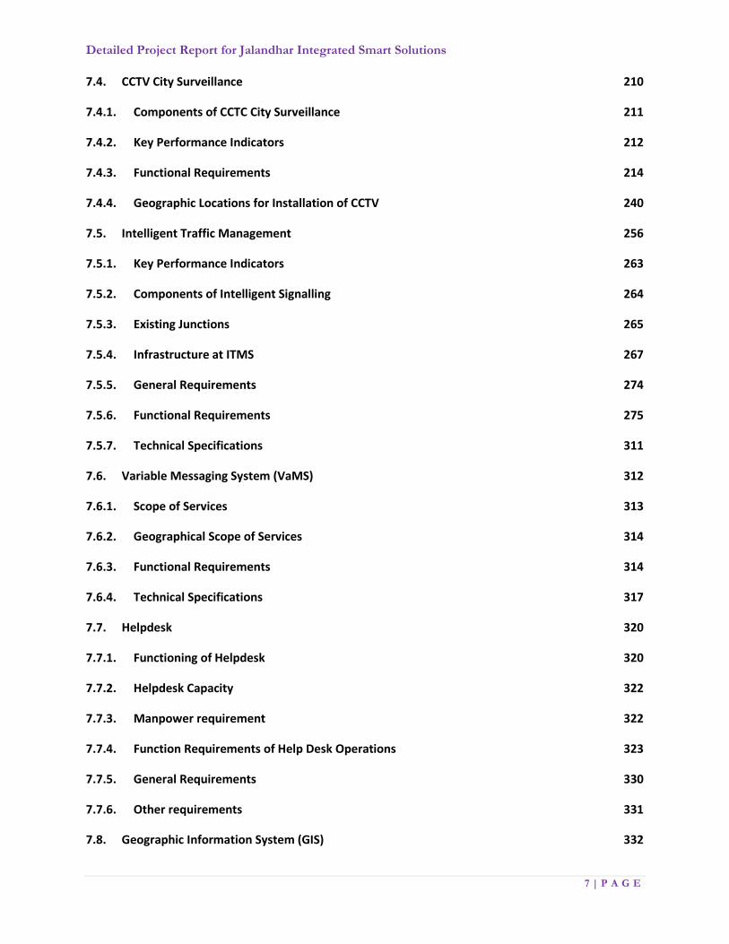
7.4. CCTV City Surveillance 210
7.4.1. Components of CCTC City Surveillance 211
7.4.2. Key Performance Indicators 212
7.4.3. Functional Requirements 214
7.4.4. Geographic Locations for Installation of CCTV 240
7.5. Intelligent Traffic Management 256
7.5.1. Key Performance Indicators 263
7.5.2. Components of Intelligent Signalling 264
7.5.3. Existing Junctions 265
7.5.4. Infrastructure at ITMS 267
7.5.5. General Requirements 274
7.5.6. Functional Requirements 275
7.5.7. Technical Specifications 311
7.6. Variable Messaging System (VaMS) 312
7.6.1. Scope of Services 313
7.6.2. Geographical Scope of Services 314
7.6.3. Functional Requirements 314
7.6.4. Technical Specifications 317
7.7. Helpdesk 320
7.7.1. Functioning of Helpdesk 320
7.7.2. Helpdesk Capacity 322
7.7.3. Manpower requirement 322
7.7.4. Function Requirements of Help Desk Operations 323
7.7.5. General Requirements 330
7.7.6. Other requirements 331
7.8. Geographic Information System (GIS) 332

Detailed Project Report for Jalandhar Integrated Smart Solutions
8 | P A G E
7.8.1. Functional requirement for GIS based City Analytics 335
7.8.2. Integration of GIS Maps with Smart City Elements 340
7.9. Disaster Management 341
7.10. Jalandhar Environmental Monitoring System (JEMS) 342
7.10.1. KPIs for Environmental Monitoring System 342
7.10.2. Scope of work 343
7.10.3. Components of Environmental Sensors 343
7.10.4. Functional Requirements 344
7.10.5. Geographical Scope 347
7.10.6. Technical Specifications 347
7.11. E-Governance 348
7.12. Integration with NERS (Mohali, Punjab) 349
7.12.1. Technical Specifications 351
7.13. Edge Analytics (Optional) 351
7.13.1. Advantages of Edge Analytics 352
8. Indicative Bill of Material and Costing Error! Bookmark not defined.
9. Project Implementation Timelines and Deliverables 356
10. Project Deliverables 356
Annexure: General Requirements 360
Annexure: Technical Requirements 368
Annexure: Use cases 380

Detailed Project Report for Jalandhar Integrated Smart Solutions
9 | P A G E
Project Background

Detailed Project Report for Jalandhar Integrated Smart Solutions
10 | P A G E
Project Background
“Smart City is referred as the safe, secure, environmentally green, and efficient urban center of the
future with advanced infrastructures such as sensors, electronics and networks to stimulate sustainable
economic growth & a high quality of life” (Hall, 2000).
Rapid growth in small and medium scale urban centres plays an important role in economic and
societal progress. However, it also strains a city’s infrastructure. Key challenges, such as traffic
congestion, energy usage, public safety, and the building of sustainable communities are top of mind.
Such challenges need to be addressed through the development and implementation of intelligent
solutions. Smart cities are measured by the integration of their infrastructure and the intelligent ways
by which they tackle challenges. A smart city puts emphasis on creating a system of networks to allow
for a systematic flow of information and effective management of resources. Enabling integration and
convergence with organizations and local authorities to provide solutions for the development of a
smart city is crucial.
A Smart City offers decent living options to every resident. This would mean that it will have to
provide a very high quality of life
i.e. good quality of affordable
housing, cost efficient physical
infrastructure such as 24 x 7 water
supply, sanitation, 24 x 7 electric
supply, clean air, quality education,
health care, security, entertainment,
sports facilities, robust and high
speed interconnectivity, fast &
efficient urban mobility etc.
Nearly 31% of India's current
population currently resides in cities and contribute to 63% of GDP (Census 2011). Urban areas are
expected to house 40% of India's population and contribute 75% of India's GDP by 2030. This
requires comprehensive development of physical, institutional, social and economic infrastructure. All
are important in improving the quality of life and attracting people and investment, setting in motion
a virtuous cycle of growth and development. Development of Smart Cities is a step in that direction.
Figure 1: Smart Elements

Detailed Project Report for Jalandhar Integrated Smart Solutions
11 | P A G E
The Smart Cities Mission is an innovative and new initiative by the Government of India to drive
economic growth and improve the quality of life of people by enabling local development and
harnessing technology as a means to create smart outcomes for citizens.
The objective of the Smart Cities Mission is to promote cities that provide core infrastructure and give
a decent quality of life to its citizens, a clean and sustainable environment and application of 'Smart'
Solutions. The focus is on sustainable and inclusive development and the idea is to look at compact
areas, create a replicable model, which will act like a lighthouse to other aspiring cities. The Smart
Cities Mission w meant to set examples that can be replicated both within and outside the Smart City,
catalysing the creation of similar Smart Cities in various regions and parts of the country.
SMART CITIES MISSION STRATEGY
Pan-city initiative in which at least one Smart
Solution is applied city-wide
Develop areas step-by-step – three models of area-
based developments
City Improvement (Retrofitting),
City Renewal (Redevelopment),
City Extension (Greenfield)
The Smart City Mission is being operated as a Centrally
Sponsored Scheme (CSS) and the Central Government
proposes to give financial support to the Mission to the
extent of Rs. 48,000 crores over five years i.e. on an average Rs. 100 Crores per city per year. An equal
amount, on a matching basis, will have to be contributed by the State/ULB; therefore, nearly Rupees
one lakh crore of Government/ULB funds will be available for Smart Cities development.
Accordingly, the purpose of the Smart Cities Mission is to drive economic growth and improve the
quality of life of people by enabling local area development and harnessing technology, especially
technology that leads to Smart outcomes.
Figure 2: Smart City Infrastructure Elements

Detailed Project Report for Jalandhar Integrated Smart Solutions
12 | P A G E
Chapter 1: Introduction
Detailed Project Report for Jalandhar Integrated Smart Solutions
13 | P A G E
1. Introduction
The purpose of this document is to provide a common core set of city-needs-led requirements, co-
developed and validated by Jalandhar city, to develop the Jalandhar city as a Smart City. The ambition
is that adoption of these requirements of Jalandhar city will lead to reduced pre-procurement times,
increased confidence in platform designs, greater levels of collaboration (particularly amongst various
line departments), innovation in government models, more affordable solutions, and a more secure
basis for Government to apply its innovations. This will lead to accelerated adoption of urban
platforms by Jalandhar city, so that they can exploit the potential of the growing volumes of city data,
and improve the services to and outcomes for their residents, line departments and visitors.
This document provides a primary input to the Smart City Platform (Platform implies an Integrated
Solutions connecting all Smart Components of the Smart City) Supply-Side and Standardisation work
streams as a reference for the development of further Functional, Technical and Operational
guidelines. The requirements illustrate the purpose and complete declaration for the development of
system, as well as system constraints, interface and interactions with other external applications. The
scope of this document is limited to current situation in the city, its reengineering, common operations
and services data platform requirements, and issues related to the management of city data within the
Pan City area, Governance Structure and the funding requirements. This considers the full life-cycle
of city data, including: the maintenance of the existing city data; development of functional
requirements for common services data platform from a city-needs perspective identification of key
beneficial areas related to the Smart City functioning.
There are number of clear trends that any city must recognise:
The astounding increase in volumes of city data, driven notably by IoT/sensor/ICT
implementations
Citizen demand for efficient services
The pressure to improve and make data available from public and private sources
The continued reality of austerity that drives cities towards transformative solutions
Detailed Project Report for Jalandhar Integrated Smart Solutions
14 | P A G E
1.1. About Jalandhar
Jalandhar, is a city in the Doaba region of Punjab and is the oldest inhabited major city in the state.
Previously, the capital of Punjab after independence, before conceding the status to Chandigarh in
1953, Jalandhar has now undergone rapid urbanization and developed into an industrial city known
for being a center of commerce. It is situated about 145 Km from the capital, Chandigarh.
The population of Jalandhar is 873,725 (Census 2011) with nearly 75% of this population being Hindu,
and the second largest religion being Sikhism at 21.39%. Jalandhar, being an industrial city, is well
known for manufacture of several goods, particularly sporting goods, surgical equipment, hand tools,
etc. Jalandhar is also renowned for the printing industry, which is among the largest in the Northern
part of the country. Jalandhar also happens to be one of the prominent education cities in the region
with the largest number of educational centres.
The city wishes to leverage its position as an industrial center with a focus on productivity, activity,
business and liveability. In the pursuit to achieve the goals set by the authorities, Jalandhar smart city
has kept the ethos of its vision aimed at (i.) Healthy Active City, (ii.) Sports City, (iii.) Entrepreneurial
& Productive City, (iv.) Manufacturing based Economy, (v.) Sustainable & Liveable City. To realize
the smart city mission, various projects under the Jalandhar Smart City initiative have been proposed
according to the SCP. Projects ranging from Urban Sanitations, to improved walkability and projects
ensuring higher quality of lifestyle have been envisaged. As a part of Smart City initiative, Integrated
Command and Control Centre too has been proposed to improve the safety and security of its citizens.
A few outlined demographics of Jalandhar are:
1. The popular spiritual places in Jalandhar include Baba Dasji Gurudwara, Tulsi Mandir, Devi
Talab Mandir, Geeta Mandir and Gurudwara Chhevin Padshahi
2. Punjab Technical University (PTU) is one of the most reputed educational field.
3. Climate: Jalandhar city has a humid subtropical climate with cool winters and long, hot
summers.
4. Population: Jalandhar city had a population of 8.62 lakhs;
5. Area: 2632 km2; Elevation: 228 m (748.03 ft.); Literacy: 82.4%.
Jalandhar is governed by a number of bodies, the most important being the Municipal Corporation
Jalandhar (MCJ) which is responsible for the master planning of the city.

Detailed Project Report for Jalandhar Integrated Smart Solutions
15 | P A G E
1.2. Jalandhar Smart City Limited (JSCL)
The Jalandhar Smart City Limited (JSCL) in the Special Purpose Vehicle (SPV) constituted as per the
directives of MoHUA, Govt. of India for executing SMART CITY MISSION (SCM) in Jalandhar.
JSCL is led by the CEO Jalandhar Smart City and works closely with the Municipal Corporation of
Jalandhar (MCJ) and other nodal offices like Police, Fire etc. with the objective to achieve success in
the implementation of Smart City Mission for Jalandhar.
JSCL has been established under the Companies Act, 2013 of the Ministry of Corporate Affairs,
Government of India. It is supported by PMC and an agency for the implementation of the mission.
1.3. Vision Statement for Jalandhar Smart City and Associated Objectives Jalandhar: The Leading Sports and Manufacturing hub in Asia” The world of sports is a growing
industry in India. A thriving sports sector has significant socio-economic impact, as it is instrumental
in improving the physical health and mental agility of human resources, and in promoting unity and
national pride. Sports as an industry have contributed 1%- 5% of the GDP of various countries.
Manufacturing is the foundation of a strong economy. The most successful countries have a strong
industrial and manufacturing presence under pinning the economic growth. Manufacturing has the
potential to help take many residents, currently living in slums, above the poverty line by providing
better paid and higher skilled jobs, goal highlighted in Make in Indian a successful mission. Jalandhar
has the opportunity to build upon its existing sports and manufacturing base to create sustainable jobs,
increase productivity and drive innovation. The city would benefit from taking a strategic approach
that will focus on the sports and manufacturing sector, including:
Becoming a leading hub for sports goods globally not just in manufacturing, so in research
and development in terms of production methods and new cutting-edge sporting goods.
Focusing on the potential of Small and Medium Enterprises ensuring they are ready to up-skill
and expand from their current low-tech base to ensure their good search national and global
consumers
In order to develop Jalandhar as envisaged and make it more liveable and sustainable, the strategic
blue print for next 5-10 entails the following

Detailed Project Report for Jalandhar Integrated Smart Solutions
16 | P A G E
1. Promote economic growth of the city by creating state of the art sports infrastructure that
aggregates the youth and attracts national/international events, exhibitions, leagues &
tournaments converging with the country's sports ecosystem.
2. To create public & recreational spaces for the benefit of the city's residents which can also
host cultural events.
3. Investing in public transport and traffic management. This will increase accessibility, reduce
congestion, promote walk-ability and ensure better parking provision leading to higher
productivity.
4. Upgrading the city’s poor public real man urban environment. Currently, a lack of safe and
inclusive spaces means that citizens cannot engage inactive and social lifestyle.
5. The city’s aging physical infrastructure needs to be upgraded to cater for an increased
population.
6. Improving urban governance by introducing smart technologies/ICT solutions that help bring
systemic efficiency in infrastructure service provision and improved two-way communication.
1.4. Project Structure
The Government of Punjab has accorded approval for implementation of Smart Cities Scheme in the
State. The High Power Steering Committee (HPSC) for Smart Cities Scheme has also been constituted
under the Chairmanship of Chief Secretary with representatives of various State Government
departments to guide the mission in the State.
The Government of Punjab has nominated Punjab Municipal Infrastructure Development Company
(PMIDC) as the State Level Nodal Agency (SLNA) and Mission Directorate.
In Punjab, Jalandhar city among the one which is selected under Smart City that aimed at
Transforming Jalandhar city to (i.) Healthy Active City, (ii.) Sports City, (iii.) Entrepreneurial &
Productive City, (iv.) Manufacturing based Economy, (v.) Sustainable & Liveable City.
Detailed Project Report for Jalandhar Integrated Smart Solutions
17 | P A G E
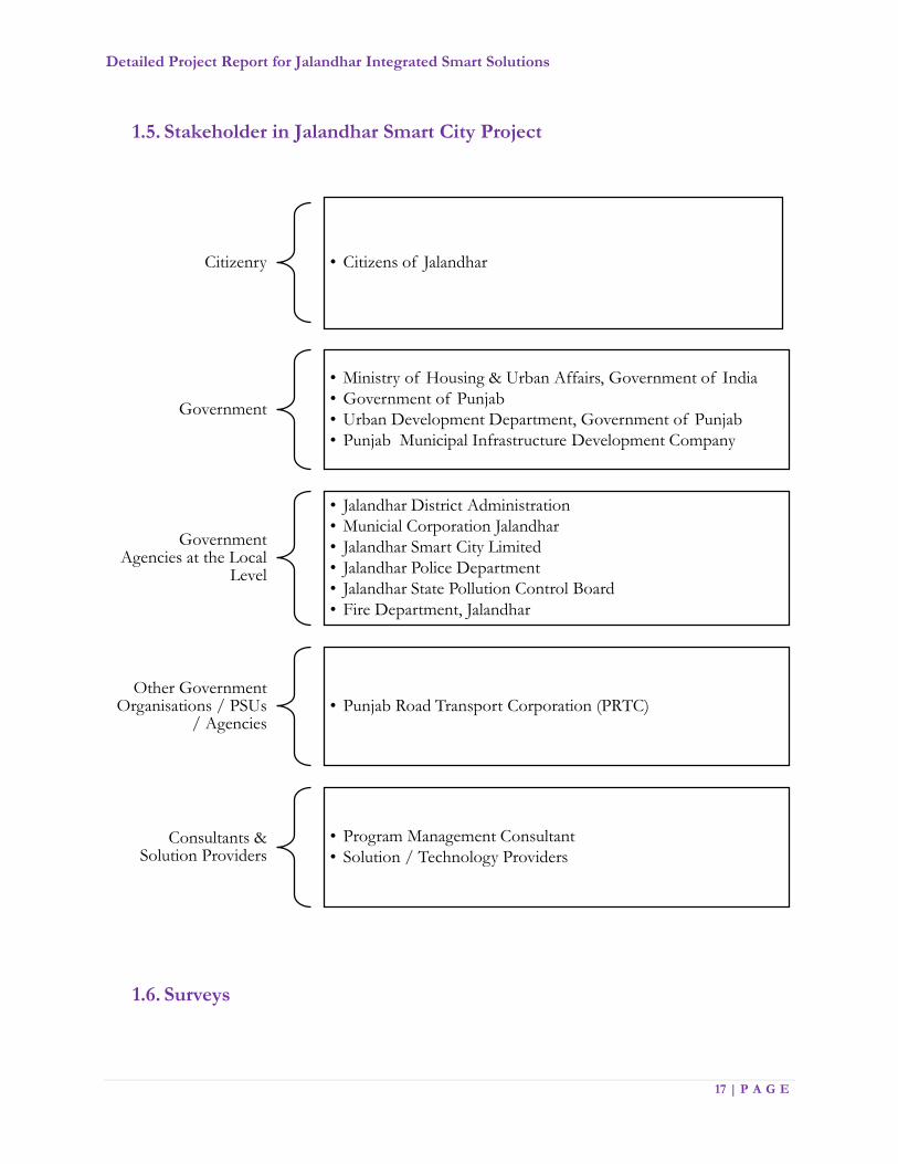
1.5. Stakeholder in Jalandhar Smart City Project
1.6. Surveys
Citizenry • Citizens of Jalandhar
Government
• Ministry of Housing & Urban Affairs, Government of India
• Government of Punjab
• Urban Development Department, Government of Punjab
• Punjab Municipal Infrastructure Development Company
Government Agencies at the Local
Level
• Jalandhar District Administration
• Municial Corporation Jalandhar
• Jalandhar Smart City Limited
• Jalandhar Police Department
• Jalandhar State Pollution Control Board
• Fire Department, Jalandhar
Other Government Organisations / PSUs
/ Agencies• Punjab Road Transport Corporation (PRTC)
Consultants & Solution Providers
• Program Management Consultant
• Solution / Technology Providers

Detailed Project Report for Jalandhar Integrated Smart Solutions
18 | P A G E
Initial stage of the Project Cycle was started with the live city surveys with the objective of depth
understanding of the current city situation in following aspects:
a) City Traffic situations and the issues
At present, there are 343 prominent junctions in Jalandhar city, which requires revamping and
the intervention of Smart equipment for seamless traffic flow management. Out of the available
multi legged junction a few are operational in traffic lights.
b) Current Security and monitoring mechanisms
With regards to city surveillance and security parameters the city devoid in proper infrastructure,
which includes monitoring tools and video surveillance analytics.
c) Approach for the Management of Solid Waste
At present solid waste management is being done across the city through vehicles and adequate
manpower deployment. It also includes vehicles, which are GPS enabled and mobile-based
attendance of the working staff.
d) Lighting arrangements at the streets
The lighting arrangement at the streets is provisioned with multi wattage lights with LED based
luminance across the city. However, these provisioned lights do not fall under smart category,
as they are not compatible with the smart controlling units that can be governed centrally.
e) Environment and Pollution Control mechanisms
At present, Air pollution is a great menace for the city. The major causes of air pollution here
are motor vehicle emissions, stubble burning in fields and illegal industrial activities, which have
adverse effects on health of the population, especially children. From the desk of the Chairman,
Punjab Pollution Control Board (PPCB), Mr. K S Pannu “The appropriate measures are being
taken in order to maintain the AQI in the city”
f) Parking Management Systems in the city
There are a few open public parking’s available in the city which does not work with the smart
equipment like boom barriers, cameras and token/ ticket management, etc.

Detailed Project Report for Jalandhar Integrated Smart Solutions
19 | P A G E
g) Network Connectivity
At present, there are a few major Network Service providers across the city; those have laid
down the OFC cabling across the city to fulfill city’s network backbone requirements. The major
players include BSNL and the likes.

Detailed Project Report for Jalandhar Integrated Smart Solutions
20 | P A G E
Chapter 2: Feasibility Study Assessment

Detailed Project Report for Jalandhar Integrated Smart Solutions
21 | P A G E
2. Feasibility Study Assessment
Infrastructure is the backbone of any successful place for living and working. A properly functioning
Smart City is a direct consequence of meticulously planned and arduously maintained infrastructural
system. This feasibility report may outline the different modules, viz. Smart Traffic Management,
Citizen Services, Environment Monitoring, and Smart Parking Management for the Smart City. The
project is expected to infuse high population growth in the project area based on the quality of life
and infrastructure facilities proposed in the smart city. Conduct a detailed scoping study and develop
a comprehensive project plan, including:
Feasibility study for finalization of detailed technical architecture and project plan
Development of traffic management plans for individual signal controls and groups of signal
controllers along with pre-planned intervention strategies for special scenarios
Site surveys to identify need for junction improvement, junction signage, lane markings and other
necessary site infrastructure
Site Clearance obligations & other relevant permissions.
2.1. Assessment Processes
As part of the assessment, PMC team conducted feasibility of implementing smart parking, video
analytics and surveillance, and a central information hub for stakeholders of Smart City. PMC team
also carried out stakeholder analysis, best practice survey and opportunity assessment during the study.
The study is based on Citizen Centricity, Impact on Climate & Reduction in Carbon footprint, User
Friendliness & Ease of usage, Economic Sustainability of Projects, Citizen Privacy and Continuous
Innovation.
2.2. Study Parameters
The feasibility has been performed on following parameters:
Use Case (Present and Future) - Illustrative scenarios comparing the lives of stakeholders with and
without the foundational initiative.

Detailed Project Report for Jalandhar Integrated Smart Solutions
22 | P A G E
Design Architecture- Technical feasibility of the initiative including solution overview, architecture
and location analysis.
Financial Viability- Economic feasibility of the initiative including revenue modelling, Capex and
Opex costs and cost benefit analysis.
Stakeholder Benefits- Qualitative benefits of important stakeholders including citizens, JSCL and
the environment.
2.3. Envisaged Smart Solution
Smart City framework envisaged five main dimensions and implement various ICT solutions.
Figure 1: Dimensions of ICT Framework
Detailed Project Report for Jalandhar Integrated Smart Solutions
23 | P A G E
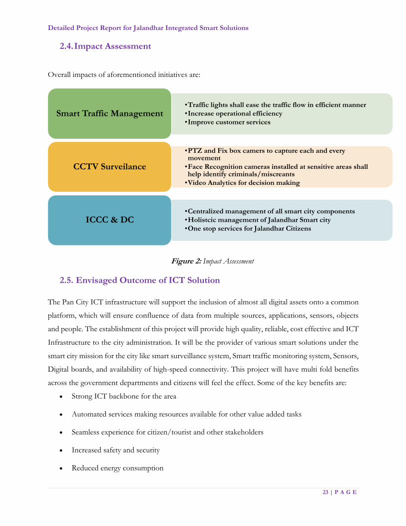
2.4. Impact Assessment
Overall impacts of aforementioned initiatives are:
Figure 2: Impact Assessment
2.5. Envisaged Outcome of ICT Solution
The Pan City ICT infrastructure will support the inclusion of almost all digital assets onto a common
platform, which will ensure confluence of data from multiple sources, applications, sensors, objects
and people. The establishment of this project will provide high quality, reliable, cost effective and ICT
Infrastructure to the city administration. It will be the provider of various smart solutions under the
smart city mission for the city like smart surveillance system, Smart traffic monitoring system, Sensors,
Digital boards, and availability of high-speed connectivity. This project will have multi fold benefits
across the government departments and citizens will feel the effect. Some of the key benefits are:
Strong ICT backbone for the area
Automated services making resources available for other value added tasks
Seamless experience for citizen/tourist and other stakeholders
Increased safety and security
Reduced energy consumption
•Traffic lights shall ease the traffic flow in efficient manner
•Increase operational efficiency
•Improve customer servicesSmart Traffic Management
•PTZ and Fix box camers to capture each and every movement
•Face Recognition cameras installed at sensitive areas shall help identify criminals/miscreants
•Video Analytics for decision making
CCTV Surveilance
•Centralized management of all smart city components
•Holistcic management of Jalandhar Smart city
•One stop services for Jalandhar CitizensICCC & DC

Detailed Project Report for Jalandhar Integrated Smart Solutions
24 | P A G E
Reduced environmental stress
Figure 3: Smart City elements

Detailed Project Report for Jalandhar Integrated Smart Solutions
25 | P A G E
Chapter 3: Our Approach
Detailed Project Report for Jalandhar Integrated Smart Solutions
26 | P A G E
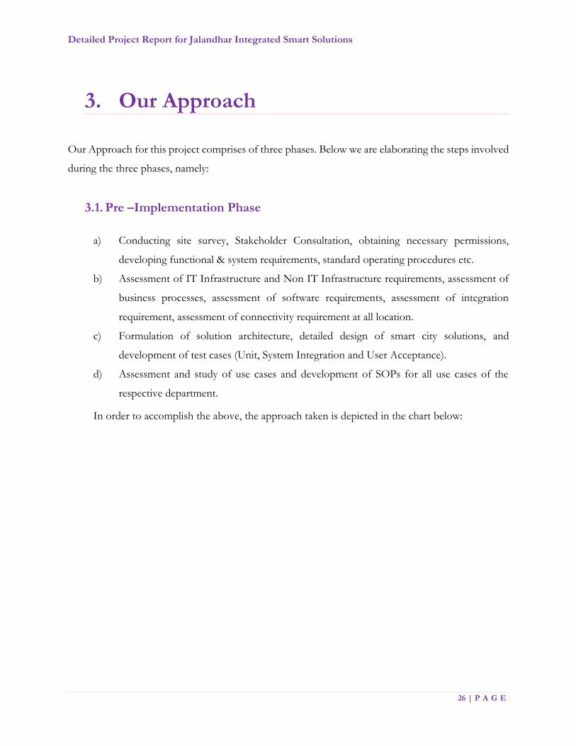
3. Our Approach
Our Approach for this project comprises of three phases. Below we are elaborating the steps involved
during the three phases, namely:
3.1. Pre –Implementation Phase
a) Conducting site survey, Stakeholder Consultation, obtaining necessary permissions,
developing functional & system requirements, standard operating procedures etc.
b) Assessment of IT Infrastructure and Non IT Infrastructure requirements, assessment of
business processes, assessment of software requirements, assessment of integration
requirement, assessment of connectivity requirement at all location.
c) Formulation of solution architecture, detailed design of smart city solutions, and
development of test cases (Unit, System Integration and User Acceptance).
d) Assessment and study of use cases and development of SOPs for all use cases of the
respective department.
In order to accomplish the above, the approach taken is depicted in the chart below:
Detailed Project Report for Jalandhar Integrated Smart Solutions
27 | P A G E
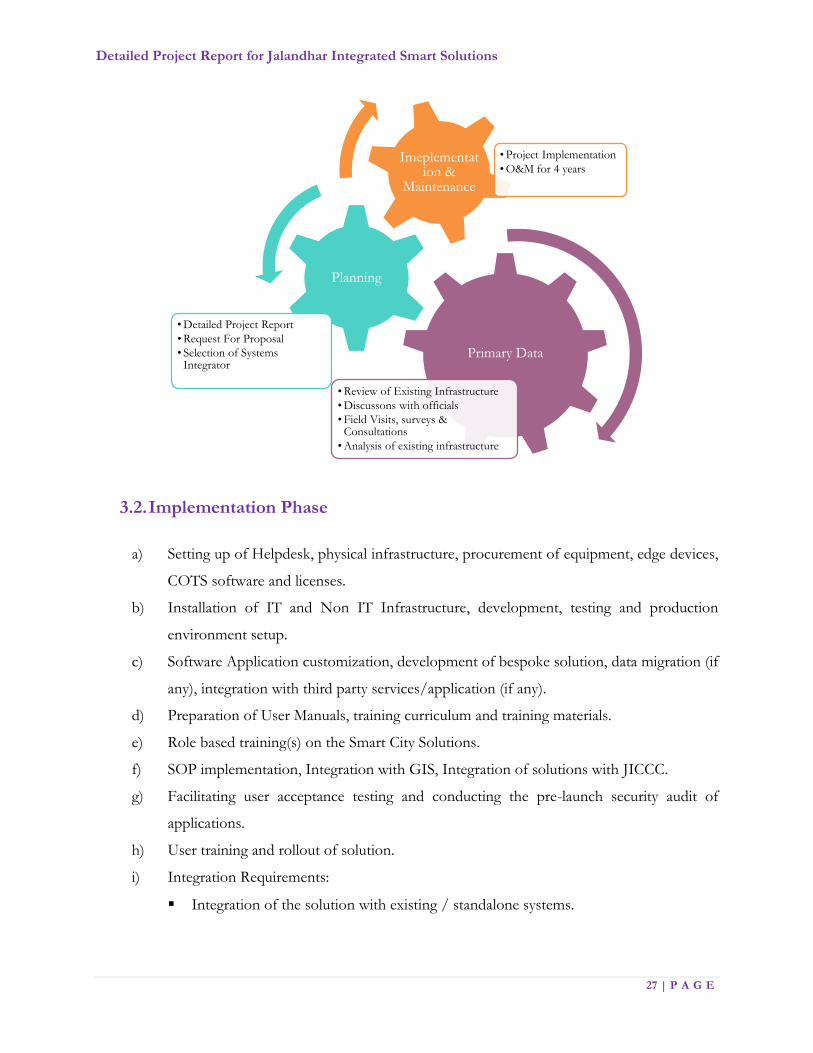
3.2. Implementation Phase
a) Setting up of Helpdesk, physical infrastructure, procurement of equipment, edge devices,
COTS software and licenses.
b) Installation of IT and Non IT Infrastructure, development, testing and production
environment setup.
c) Software Application customization, development of bespoke solution, data migration (if
any), integration with third party services/application (if any).
d) Preparation of User Manuals, training curriculum and training materials.
e) Role based training(s) on the Smart City Solutions.
f) SOP implementation, Integration with GIS, Integration of solutions with JICCC.
g) Facilitating user acceptance testing and conducting the pre-launch security audit of
applications.
h) User training and rollout of solution.
i) Integration Requirements:
Integration of the solution with existing / standalone systems.
Primary Data
• Review of Existing Infrastructure
• Discussons with officials
• Field Visits, surveys & Consultations
• Analysis of existing infrastructure
Planning
• Detailed Project Report
• Request For Proposal
• Selection of Systems Integrator
Imeplementation &
Maintenance
• Project Implementation
• O&M for 4 years

Detailed Project Report for Jalandhar Integrated Smart Solutions
28 | P A G E
Develop provisions for a scalable system which can integrate with more devices of the
same kind (as those deployed today) and can integrate with future applications and
sensors through open standards and data exchange mechanisms.
3.3. Post Implementation Phase
a) Deploying manpower for solution maintenance and monitoring support which includes
change request management, bug tracking and resolution, production support, performing
version and patch updates.
b) Annual technical support for all hardware and software components for the O&M period.
c) Detailing of SOPs and their optimization during operation and maintenance phase.
d) Optimizing field infrastructure for better operations, e.g., shifting of cameras or changing
their alignment / angle.
e) Identifying, scripting and implementing the automation required to manage the IT during
O & M phase.
f) Continuously study the additional requirements, fine-tune the applications and implement
features that will assist the line departments in carrying out the operations thereby
stabilizing the overall infrastructure
g) Preventive, repair, maintenance and replacement of hardware and software components
as applicable under the warranty and AMC services during the project period.
h) Provide a centralized Helpdesk and Incident Management
i) Recurring refresher trainings for the users and Change Management activities.
j) Conducting disaster recovery site testing through regular mock drills.

Detailed Project Report for Jalandhar Integrated Smart Solutions
29 | P A G E
Chapter 4: Integrated ICT Components
Detailed Project Report for Jalandhar Integrated Smart Solutions
30 | P A G E
4. Integrated ICT Components
The citywide network of Smart Elements will accomplish the following broad objectives:
Make Jalandhar a better place by increasing safety and liveability of the people in the city by
effectively providing the delivery of citizen services.
Improve the situational awareness of the city administrators and residents.
Provide administrators, citizens, tourists, businesses real time, and actionable information to aid
their day-to-day decision-making.
The Overall project scope comprises of end-to-end ICT Solutions, which shall cater to the following
primary components:
1. Jalandhar Integrated Command Control Center (JICCC)
2. Data Centre & Disaster Recovery (DC & DR)
3. Helpdesk
4. City Surveillance System & Intelligent Traffic Management System (JITMS)
5. Body Cameras
6. Disaster Management
7. Jalandhar Environmental Monitoring System (JEMS)
8. GIS Maps real time integration with Smart City Applications
9. e-Governance
10. Network from Service Providers
11. Others: Support the Management and Operations in infrastructure are Unified
Communications, Integrated dashboard, Video Wall & Controller System, Operator work
station, Standard Operating Procedure Tools (SOP), Security Management, Intrusion
Detection, Antivirus Management, Remote Device Management, Internet Connectivity, IT
Service Management (ITSM), Building Management System (BMS).

Detailed Project Report for Jalandhar Integrated Smart Solutions
31 | P A G E
Chapter 5: Project Undertakings

Detailed Project Report for Jalandhar Integrated Smart Solutions
32 | P A G E
5. Project Undertakings
In order to execute the Project, the Master System Integrator (MSI) shall be selected through a
transparent Bid Process. The Master System Integrator (MSI) is the agency that shall implement
the project based on the scope of work provided in the Bid Documents its responsibilities shall
include establishing a dedicated Data Centre and the State-of-Art, innovative ICT solutions to
revive & revamp City of Jalandhar using Hi-Tech solutions.
The MSI shall be responsible for carrying out the following activities:
A. Project Planning, Mobilization & Management and Maintenance of the project
B. Survey and Detailed Design of all Smart Solutions Components
C. Prototype Acceptance and Factory Acceptance Testing
D. Hardware Supply and Installation Stage
E. Software Development (if any)
F. System Study, Design, Development, Integration, Testing and Certification
G. System Integration
H. Testing
I. Third Party Acceptance Testing, Audit and Certification
J. Capacity building & Training
K. Change Management
L. Final Deployment and Documentation
M. Operational System Acceptance
N. Comprehensive Maintenance for System and Services
O. Support Staff Required

Detailed Project Report for Jalandhar Integrated Smart Solutions
33 | P A G E
5.1. Team Mobilization, Project Planning & Management/ Maintenance Management
MSI need to deploy a dedicated team of experts to execute the project. MSI shall be responsible
for end to end project management for the Implementation and Operations & Maintenance of
the Project. The Project team include but limited to Project Director, Project Manager along with
Solution and Network Architect. The Project Manager shall be the single point of contact that
shall assume overall responsibility of the Project and ensure end-to-end working of the project.
MSI shall be responsible for preparing a master schedule of work, which shall highlight
implementation plan for all the Project Milestones. The schedule shall identify the manufacture,
delivery, installation, integration of equipment (Software and Hardware), training programs, test
procedures, delivery of documentation and the respective solutions. The schedule shall include
JSCL and any third party responsibilities along with the activities in the timeline.
MSI shall also be responsible for effective risk and issue management and escalation procedures
along with matrix as part of project management. MSI shall identify, analyse, and evaluate the
project risks and shall develop cost effective strategies and action plan for mitigation of risks. As
part of the Project, MSI shall monitor report and update risk management plans and will discuss
during project meetings. MSI shall propose a suitable progress reporting mechanism for the
project duration.
The Enterprise Project Management Tool needed to be deployed by MSI, which should cater to
effective project management, configuration management, issue and risk management, escalation
procedure and matrix document repository etc. Based on progress reports, MSI shall also
accordingly update the master schedule of work on a continuous basis during the project period.
5.2. Survey and Detailed Design of all Smart Solutions Components
MSI shall conduct end-to-end survey of the site area, based on the observations asses, and validate
the present conditions, implementation approach and methodology, project challenges and
mitigations and other project critical information. During the survey stage itself, MSI shall
mobilize its entire staff and fully acquaint them with the site conditions. It is MSI’s responsibilities
to periodically survey the site and provide update on the project during the project period.

Detailed Project Report for Jalandhar Integrated Smart Solutions
34 | P A G E
During the design stage, MSI would also expected to:
Conduct Workshops with different stakeholders for capturing business requirements,
creating awareness of best practices, communicating the changes, building consensus on
process design etc. Workshops need to be organized at different intervals and in different
places throughout the duration of the projects as needed.
Stake holder consultation - Other than the workshops with those stake holders, PMC &
JSCL identified staff will provide critical inputs, reviews, suggestions, process description
etc.
Review sessions will be organizing with different stakeholders for signing off the
deliverables, walking through the deliverables for facilitating quick understanding.
The MSI shall be responsible for the detailed design of the Jalandhar smart city solutions. MSI
shall discuss in detail with the JSCL or its representatives the detailed design of the Jalandhar Smart
City Solutions and fine-tune any requirements. It is the MSI’s responsibility to satisfy the
operational requirements of the JSCL and adopt industry best practices for implementation during
the design stage itself. Based on the survey observation, analysis and discussion with the JSCL, the
MSI shall submit a Detailed Design Report. The IT deliverables would include following details
and not limited to JICCC design/layout, System Architecture, Data center Architecture, Network
Architecture, Application Architecture, Security Architecture, Routing & Switching, Integration,
Operational procedures etc.
The detailed design report shall include end-to-end design validation for the project including
project understanding, analysis, detailed design, integration plan, and construction drawings.
Complete set of design and construction drawing including method of installation as applicable
shall also be included in the Detailed Design Report. Construction details shall accurately reflect
actual job conditions.
All technical data sheets of the products must be submitted ahead of time by the MSI. It is MSI’s
responsibility to get all technical data sheets approved by the JSCL or its representative to meet
the overall project schedule.

Detailed Project Report for Jalandhar Integrated Smart Solutions
35 | P A G E
Design and Construction drawings shall include the following at a minimum for drawings for all
the elements as part of holistic solution:
Overall design
Cable requirements, routing and location (as applicable)
Design of IP address and schematic architecture diagram
Typical mounting details
Single Line Diagrams (SLDs)
Splicing diagrams
Wiring diagrams with diagram
3D layouts and renderings
Any other layouts
All drawings shall be updated/revised to “as-built” conditions when installation is complete.
Design submissions should base on project requirements and shall include as applicable, but not
limited to, the following:
Complete listing of specifications to be used along with detailed technical data sheet
Detailed engineering drawings
Shop drawings including product data sheets
Revisions to original design submissions.
MSI need to design requirement analysis documents for various components of the solution. This
includes System Requirements Specification (SRS) and Functional Requirements Specification
(FRS) documentation. The MSI shall be responsible for documenting any existing/planned
‘processes’ of the JSCL as part of these deliverables.
5.3. Prototype Acceptance and Factory Acceptance Testing
After approval of the technical data sheets by JSCL or its representative, MSI shall submit the
prototype of all the material presented in the Detailed Design Report for its review and approval.
Note: It shall be MSI’s responsibility to get the prototypes approved in due course of time without
affecting the overall schedule of completion of works.

Detailed Project Report for Jalandhar Integrated Smart Solutions
36 | P A G E
Material provided as part of the Project shall undergo Prototype Acceptance Test (PAT) and
Factory Acceptance Test (FAT) as per Project Plan. MSI shall present respected reports to the
JSCL and its representatives the test results for PAT and FAT in the form of Test Result
Documentation. JSCL at its own discretion shall visit any FAT site. MSI shall be responsible for
organizing all logistics required for this site visit. For all the software components, MSI shall also
propose prototype of solution components in this phase and get the required approvals.
5.4. Hardware Supply and Installation Stage
MSI shall be responsible for the supply and installation of all components as part of the Project
to meet the Technical, Functional, Business and Performance requirements that will be mention
in BID DOCUMENT. No deviations from these requirements shall be acceptable by JCSL. MSI
shall deliver the project, install and handle the equipment in accordance with manufacturer’s
requirements. Installation process of the MSI shall be flexible and shall accommodate JCSL
requirements.
MSI shall be responsible for all supply, storage and handling of the material as mentioned in Bid
Document. The OEM proposed for the IT infrastructure shall be in line with the national security
policy (as applicable).
If there is removal/change of any existing material during installation process and belongs to the
JSCL, the material should handed-over to the JSCL. MSI shall also be responsible for reinstating
any site in the project limits at no additional cost to JSCL. It shall be the MSI’s responsibility to
supply and install all hardware in compliance with the requirements. MSI shall be responsible for
all implementation works on the project including any civil, structural, electrical, etc. works
required to meet the project requirements.
5.5. Software Development
MSI shall be responsible for development and deployment of all software to meet the
requirements of the project. It is preferred that MSI will use a world class Commercially Off The
Shelf (COTS) or widely used software packages. However, some of the modules may require
bespoke development. MSI shall be fully responsible for developing and implementing all software
Detailed Project Report for Jalandhar Integrated Smart Solutions
37 | P A G E
required for the project. The development model should be Agile. The software development
should base on the approved software and functional requirements specifications. The technology
platform chosen for all software should be based on industry standards and shall be secure.
Migration of data shall be the responsibility of the MSI. MSI is required to take the source data in
the format, which is available with department. Subsequently, MSI is required to take complete
ownership of data migration and develop a detailed plan for data migration. MSI will create SRS
for application development and get approval from JSCL for UI design before commencing
development and periodic review meetings should schedule for review of application and progress
of the project.
5.6. System Study, Design, Development, Integration, Testing and Certification
MSI would be responsible for development, adding functionality/Customizing over and above
the applications (COTS product) or any bespoke software (If required) based on the unique
requirements of JSCL/MCJ/Other Stakeholders. For the additional functionality that the JSCL
wants to add, the MSI shall carry out a detailed systems study to refine the Functional
Requirements Specifications that will be provide in Bid Document and formulate the System
Requirements Specifications (SRS). The study should also include different integration points of
JICCC with external agencies as per JSCL requirement. The MSI should also prepare a detailed
document on the implementation of the customized or developed product with respect to
configuration, customization and extension as per the requirement of JSCL. The MSI would also
prepare a change/reference document based on changes or deviations from the base version of
the application (COTS product).
MSI need to ensure the overall holistic operations. The MSI should also prepare a detailed
document on the implementation of the customized or developed product with respect to
configuration, customization and extension as per the requirement of JSCL. The MSI would also
prepare a change/reference document based on changes or deviations from the base version of
the application (COTS product).
The MSI will also be responsible for the following course of activities:
Conducting Site preparation study for hardware, networking and office infrastructure
Detailed Project Report for Jalandhar Integrated Smart Solutions
38 | P A G E
Preparation of System Requirements Specifications (SRS) for additional functionalities
and different integration points with External Agencies.
Preparation of implementation document with respect to Configuration,
Customization and extensions as per the requirement of JSCL.
Preparation of the Solution Design.
Solution Development and/or Customization and/or Configuration and/or
Extension as required.
Development of reports
Formulation of test plans and test cases for additional functionalities and different
integrations with external agencies.
Preparation of Change/Reference document which will include all the changes or
deviations from the base version of the product.
Testing of the configured solution and additional functionalities.
Enhancements of functions / additions of new modules / integration requirements to various
interfaces (as and when they happen) should incorporated in the SRS.
Creation of Test Plans: - Once the SRS is approved and design is started, the MSI would
prepare all necessary Test Plans (including test cases), i.e., plans for Unit Testing, Integration
and System Testing and User Acceptance Testing. Test cases for UAT will be developed in
collaboration with domain experts identified by the JSCL. The Test Plans also include planning
for the testing any integration with third party COTS solutions, any external agencies. The
Test Plans should also specify any assistance required from the JSCL. The MSI should have
the Test Plans reviewed and approved by JSCL. JCSL need to sign off on the test plans.
High Level Design (HLD): - Once the SRS will be approved, the MSI would complete the
HLD and all HLD documents of the additional functionalities, integration with external
agencies upon the approved SRS. The MSI would prepare the HLD and have it reviewed and
approved by JSCL. JSCL will sign off on the HLD documents on the advice of JSCL.
Detailed (Low Level) Design (LLD): - The LLD would interpret the approved HLD to
help application development and would include detailed service descriptions and

Detailed Project Report for Jalandhar Integrated Smart Solutions
39 | P A G E
specifications, application logic (including pseudo code) and UI design (screen design and
navigation). The MSI would have the design documents reviewed and approved by JSCL.
Application Development and Unit Testing: - The MSI would develop the application in
accordance with the approved requirements specifications and design specifications and
according to the approved Project Plan; and carry out the Unit Testing of the application in
accordance with the approved test plans. The MSI would also implement the changes
proposed in the Change/Reference document and carry out a thorough regression testing for
the functionality. The user acceptance testing and fine-tuning of the application would be at
JSCL location.
Regression, Integration, System and Functional Testing: - After successful unit testing
of all components, the MSI would conduct full-fledged integration testing, system testing and
functional testing in accordance with the approved Test Plans for the configured/customized
product, additional functionalities and also integration with external agencies. This would
include exhaustive testing including functional testing, performance testing (including load and
stress), scalability testing and security testing. The MSI’s experts should do functional testing.
Regression testing should be conduct for those functionalities identified in Change/Reference
document to provide a general assurance that no additional errors have cropped up in the
process of addressing the customizations and/or extensions. Making all necessary
arrangements for testing including the preparation of test data, scripts if necessary and setup
of test environment (across multiple platforms) shall be the responsibility of the MSI. The
MSI along with JSCL should take the responsibility in coordinating with JSCL and other
stakeholders for a smooth integration.
Test Reports: - The MSI shall create test reports from testing activities and submit to JSCL
for validation.
Test Data Preparation: - The MSI shall prepare the required test data and get it vetted by
JSCL. The test data shall be comprehensive and address all scenarios identified in the test
cases. The MSI should also prepare the test data for all required integrations with external
agencies.
Detailed Project Report for Jalandhar Integrated Smart Solutions
40 | P A G E
User Acceptance Testing (UAT): - Test Plans for UAT would be prepare by the MSI in
collaboration with JSCL and his nominated domain experts. The MSI will plan all aspects of
UAT (including the preparation of test data) and obtain required assistance from JSCL to
ensure its success. JSCL will assemble representatives from different user groups based on
inputs from the MSI and would facilitate UAT. The MSI would make the necessary changes
to the application to ensure that the customized/developed product successfully goes through
UAT.
5.7. System Integration
MSI shall be responsible for the integration of all hardware and software supplied as part of
this Project as per the technical and performance requirements that will be mentioned in BID
DOCUMENT.
It shall be the responsibility of MSI to take approval of JSCL for the Integration of the overall
system. Post systems integration, JSCL shall review and approve the overall performance of
the integrated system as per the requirements of the BID DOCUMENT. MSI shall be
responsible for fixing any requirements that do not comply with the overall requirements and
approved detailed design at no additional cost to JSCL. MSI shall also carry out SMS Gateway
Integration with the JICCC provided by Centre for e-Governance (CeG), Government of
Punjab to send mass SMSs to groups/individuals, which can be either manual or system
generated.
5.8. Testing
All materials, equipment, systems, manufacturing or configuration processes, or other items
under this project should be inspected and tested in accordance with the requirements. The
testing shall include any existing civil infrastructure equipment or materials to taken over by
the MSI. Approvals or passing of any inspection by JSCL shall not, however prejudice the
right of JSCL or its representative to reject the material if it does not comply with the
specification or requirements that will be mention in Bid Document. The MSI shall design
and successfully complete tests to demonstrate that all equipment, materials and systems
furnished and installed function in the manner intended and in full compliance with the

Detailed Project Report for Jalandhar Integrated Smart Solutions
41 | P A G E
requirements that will be mentioned in the BID DOCUMENT and the approved detailed
design of the MSI.
All tests shall be subject to inspection or witnessing of tests by JSCL or its representative. MSI
shall submit an Acceptance Test Procedures document (ATP), for JSCL approval prior to
undertaking any testing.
The ATP shall clearly address:
Type of testing and device to be tested
How each testable specification requirement will be demonstrated, including the test
environment and set-up, specific functionality to be tested, method for performing
the test and quality assurance procedures;
The results that will constitute success for each test
The location for testing
Personnel required to conduct the test
Approximate time required to execute the test or set of tests
Responsibilities of both the MSI and JSCL representatives during each test; and
A cross-reference to which project requirements from the Compliance Matrix (to be
developed by the MSI) are being addressed by each test procedure
The Compliance Matrix shall be used as a “punch list” to track whether requirements have
not yet been demonstrated at each stage of testing. A requirement classified as having been
“demonstrated” during a certain ATP stage can be subsequently redefined as having been “not
demonstrated” if compliance issues emerge prior to System Acceptance. ATP shall be
submitted to JSCL at least three (3) weeks in advance of any intended testing.
The equipment shall be inspected for standards of construction and electrical and mechanical
safety. MSI will take appropriate certificate from the supplier. The MSI shall make test results
available to JSCL or their designate for review immediately after completion of the tests.
ATP shall incorporate the following distinct stages for each deployed stage:
System Integration Testing (SIT): The MSI is responsible for the proper and
harmonious operation of all subsystems. Where connections of the new systems to
Detailed Project Report for Jalandhar Integrated Smart Solutions
42 | P A G E
existing subsystems or equipment supplied by others are required, the MSI is responsible
for connection of equipment that will be specified in the Bid Document. Such a test will
verify the full functionality of each subsystem, as they are interconnected. This will require
testing to be coordinated by the MSI with JSCL or their designate. This work carried out
under the direction of JSCL or their designate.
The MSI shall:
Complete all equipment and subsystem tests
Test each subsystem independently on the communications subsystem
Add subsystems one at a time and monitor the overall performance
Fail safe testing of all subsystems one at the time while monitoring overall systems
performance
Stress and Load Testing: Comprehensive stress and load testing of e-Governance and Smart
elements applications shall be conducted to demonstrate robustness and reliability of the
system where necessary like Surveillance, Vehicle Tracking for SWM, Mobile App users etc.
Security Testing (including penetration and vulnerability test): Security test should be
conducted to demonstrate security requirements at network layer and software applications.
Components shall pass vulnerability and penetration testing for rollout of each phase.
Components shall also pass web application security testing for portal, Mobile App, and other
systems. Penetration test shall be carried out periodically and vulnerability analysis shall be
carried half-yearly during maintenance phase. For all applications hosted on-cloud or hosted
on premises, the security testing shall be a mandatory requirement.
System Acceptance Tests (SAT): SAT shall be conduct after the entire system has been
installed, integrated and commissioned. Deficiencies, if any shall be rectified before the
initiation of Burn-in Test. JSCL representatives shall witness SAT. SAT will carry out data
migration, if any prior to commencement of this stage. SAT shall also include any performance
and load testing for the software applications.
Operational Acceptance Test: It shall be conducted after successful SAT and Burn-in tests.
Continuous fault free running of the System shall be tested. Post the completion of

Detailed Project Report for Jalandhar Integrated Smart Solutions
43 | P A G E
Operational Acceptance Test, System shall be considered for Operational System Acceptance
and Defect Liability Period (DLP) shall commence. Operational Acceptance Test shall include
the following
Completion of all activities and fulfilment of all business, functional and technical
requirements that will be listed in BID DOCUMENT
Scrutiny of all inspection reports, audit findings, Contracts, licensing agreements etc.
MSI shall provide written Test Results Documentation (TRD) within one week of completing
each stage of testing. The TRD shall document the results of each ATP procedure and provide
an updated Compliance Matrix that indicates requirements that will be mentioned in BID
DOCUMENT. The TRD must be approve before JSCL will grant System Acceptance. A
sample format for the TRD is mention below:
Item # Date
Item Description Tester
Test
Test Setup:
Clause Test Procedure Expected Results Actual Results
Witnessed: (This Does Not Constitute Approval) Reviewed and Approved:
5.9. Third Party Acceptance Testing, Audit and Certification
The primary goal of Acceptance Testing, Audit & Certification is to ensure that the system
meets requirements, standards, and specifications that will be mentioned in the BID
DOCUMENT as needed to achieve the desired outcomes. The basic approach for this will be
ensuring that the following are associated with clear and quantifiable metrics for accountability:
Functional requirements
Test cases and Requirements Mapping
Infrastructure Compliance Review
Availability of Services in the defined locations
Performance and Scalability
Security / Digital Signatures
Manageability and Interoperability
Detailed Project Report for Jalandhar Integrated Smart Solutions
44 | P A G E
SLA Reporting System
Project Documentation
Data Quality Review
As part of Acceptance testing, audit and certification should be performed through a third
party agency. JSCL shall review all aspects of project development and implementation
covering software, hardware and networking including the processes relating to the design of
solution architecture, design of systems and sub-systems, coding, testing, business process
description, documentation, version control, change management, security, service oriented
architecture, performance in relation to defined requirements, interoperability, scalability,
availability and compliance with all the technical and functional requirements. A different
agency should be selected to conduct third party audit. Such an involvement of the Acceptance
Testing & Certification agencies (STQC/CERT-IN Empanelled Agency),
nominated/appointed by MSI with prior approval of JSCL, will not, however, absolve the MSI
of the fundamental responsibility of designing, developing, installing, testing and
commissioning the various components of the project to deliver the services in perfect
conformity with the SLAs.
Following discusses the acceptance criteria to be adopt for system as mentioned above:
Functional Requirements: - The system developed/customized by MSI shall be reviewed
and verified by the agency against the Functional Requirements signed-off between JSCL and
MSI. Any gaps, identified as severe or critical in nature, shall be addressed by MSI immediately
prior to the deployment of the system in production. One of the key inputs for this testing
shall be the traceability matrix to be develop by the MSI. Apart from Traceability Matrix,
agency may develop its own testing plans for validation of compliance of system against the
defined requirements. The acceptance testing w.r.t. both independent third party agency
(external audit) as well as the selected internal department users (i.e. User Acceptance Testing)
shall perform the functional requirements.
Infrastructure Compliance Review: - Third party agency shall perform the Infrastructure
Compliance Review to verify the conformity of the Infrastructure supplied by the MSI.
Compliance review shall not absolve MSI from ensuring that proposed infrastructure meets
the SLA requirements.
Detailed Project Report for Jalandhar Integrated Smart Solutions
45 | P A G E
Security Review: - The software developed/customized for system shall be audit by the
agency from a security & controls perspective. Such audit shall also include the IT
infrastructure and network deployed for system. Following are the broad activities to be
perform by the Agency as part of Security Review. The security review shall subject the system
for the following activities:
a) Audit of Network, Server and Application security mechanisms
b) Assessment of authentication mechanism provided in the application /components/
modules
c) Assessment of data encryption mechanisms implemented for the solution
d) Assessment of data access privileges, retention periods and archival mechanisms
e) Server and Application security features incorporated etc.
Performance: - Performance is another key requirement for system and agency shall review
the performance of the deployed solution against certain key parameters defined in SLA that
will be mention in the Bid Document. Such parameters include request-response time, work-
flow processing time, concurrent sessions supported by the system, Time for recovery from
failure, Disaster Recovery drill etc. The performance review also includes verification of
scalability provisioned in the system for catering to the requirements of application volume
growth in future.
a) The MSI must provide System and Database Performance System for all servers in
the Data center
b) The MSI must provision for End-User response time monitoring and transaction
based deep-dive analysis for Web based applications.
c) The MSI must provision for Integrated Performance Management System for
Monitoring Networks, Systems & Databases.
d) The MSI must provide a Traffic Analysis and Reporting System for deep-dive
diagnostics.
Availability: - The system should be designed to remove single point failures. Appropriate
redundancy should be built into all the critical components to provide the ability to recover
from failures. The agency shall perform various tests including network, server, security,

Detailed Project Report for Jalandhar Integrated Smart Solutions
46 | P A G E
DC/DR fail-over tests to verify the availability of the services in case of component/location
failures. The agency shall also verify the availability of services to all the users in the defined
locations.
5.10. Capacity building & Training
Post the system integration, MSI shall train JSCL representatives to operate the equipment
installed and to conduct any routine diagnostics and routine maintenance work. Training activity
shall be done during Pilot Deployment and before Final Deployment. JSCL and MSI shall mutually
agree upon the period of training. The actual number of each of above categories of trainees will
be provide at Design Stage.
The main challenges to be address effectively by the MSI are the diverse trainee base, wide
variability in education and computer proficiency and minimal availability of time. The MSI holds
the responsibility for creation of a detailed and effective training strategy, user groups and
classifications, training plan and guidelines, detailed training material, training program designed
and their delivery to the target groups.
Develop Overall Training Plan: MSI should do the finalizing of detailed Training Plan for
the program in consultation with JSCL covering the training strategy, environment, training
need analysis and role based training curriculum. MSI shall own the overall Training plan
working closely with JSCL. MSI shall coordinate overall training effort. Following is the
indicative list of the training programs that needs to be administered to the group of officials.
The overall responsibility of administering the training program lies with the MSI.
Awareness and sensitization of benefits of IT
Basic Computer Awareness & Role based training for application users
Trainers Training
System Administration & Support Training
The Training Plan (TP) shall be develop for each component / module and shall include the
training schedule and course outlines. The MSI must provide the Training Plan for review to
JSCL at least three weeks in advance of the start of training. The Training Plan must be
approved by JSCL before commencement of training.
Detailed Project Report for Jalandhar Integrated Smart Solutions
47 | P A G E
MSI shall deliver training to the end users utilizing the infrastructure at the designated Training
Centres. Role based training for the Senior Officers shall be conducted at a suitable location
by the MSI. Most of the training would be an Instructor-Led Training (ILT) conducted by
trained and qualified instructors in a classroom setting. To maintain consistency across
trainings, standard templates should be used for each component of a module.
Develop Training Schedule and Curriculum: MSI shall develop and manage the training
schedule in consultation with JSCL, aligned with the overall implementation roadmap of the
project and coordinate the same with all parties involved. Training schedule shall be developed
by solution and shall be optimized to reduce business impact and effective utilization of
Training infrastructure and capacities. The training curriculum should be organized in
modules.
Learning Management System and Training Portal: Developing a Learning Management
System and Training Portal for providing access to all training content online including
documents, demo, audio, video, simulation and practice, assessment, self-learning and context
sensitive help and monitoring, support and reporting. Learning management tool shall be a
simple webpage comprising of training materials arranged in modular approach. The tool shall
have user manuals, audio, video etc. with user specific roles and responsibilities.
Training Programs / Curriculum: Following is the indicative list of the training programs
that needs to be administer to the group of officials as identified below. The overall
responsibility of administering the training program lies with the MSI.
Basic IT skills and use of computers to creating awareness about the benefits of ICT
and basic computer skills
Role-based training on the COTS based applications (Basic and Advanced) - This
training should be in a role based, benchmarked and standardized format, and shall be
available in English/Hindi/Punjabi and lead to learning completion and assessment.
It should also allow for self-learning and retraining. Training would include mechanism
for demonstration using audio / video / simulated / demo practice exercises.
System Administrator training: a few members of the various departmental staff with
high aptitude would be trained to act as system administrators and trouble-shooters
for the system.

Detailed Project Report for Jalandhar Integrated Smart Solutions
48 | P A G E
Customization of the Training Manuals, User Manuals, Operational and Maintenance
Manuals provided along with the Software.
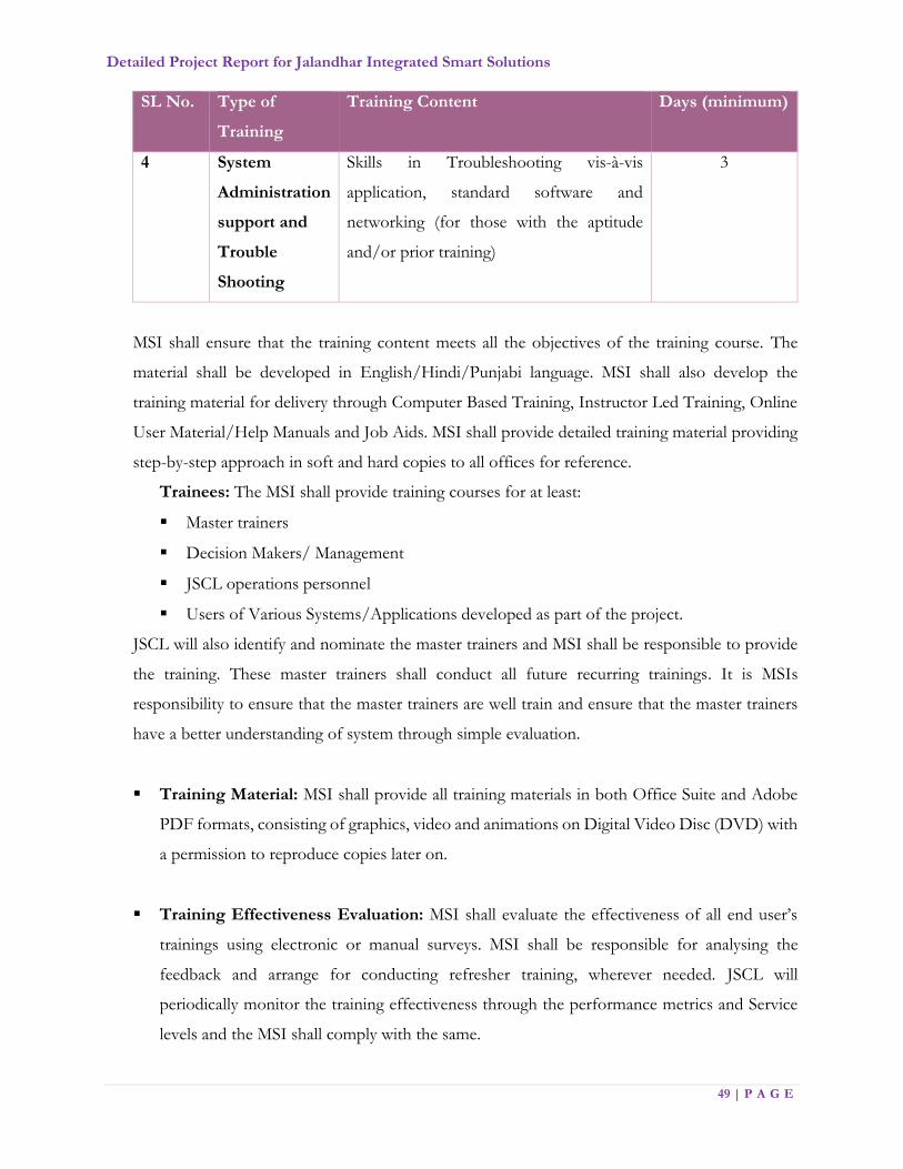
An indicative content structure for the training programs are list as below:
SL No. Type of
Training
Training Content Days (minimum)
1 Awareness and
sensitization
of benefits of
ICT
This module shall cover Principles of e-
governance; it shall also cover the
advantages of use of ICT in CCTV
Surveillance, ITMS and MCJ etc. It shall
briefly cover the technology trends and
how it can be put to use by use of live
examples of ICT use across the world
1
2 Basic
computer
awareness
This module shall cover the fundamental
concepts of Computer, Internet,
Peripherals, System software and
Application Software It shall also cover the
use of Office suite in detail. It can also
touch upon use of office tools such as
printers, copiers and scanners as well as
basics in use of computers (checking
network connections, etc.).
1
3 Role based
system
training on
The JICCC
Application
Software
This module is required to train the officials
of various levels in operating the
application. The training is to be provided
to the staff depending upon their role and
responsibilities in the workflow. During
this training, the trainees could also be
asked to carry out the routine functions
using the software. The training should be
module based and cover all modules of
JICCC. Training materials should be
provided to users
2
Detailed Project Report for Jalandhar Integrated Smart Solutions
49 | P A G E
SL No. Type of
Training
Training Content Days (minimum)
4 System
Administration
support and
Trouble
Shooting
Skills in Troubleshooting vis-à-vis
application, standard software and
networking (for those with the aptitude
and/or prior training)
3
MSI shall ensure that the training content meets all the objectives of the training course. The
material shall be developed in English/Hindi/Punjabi language. MSI shall also develop the
training material for delivery through Computer Based Training, Instructor Led Training, Online
User Material/Help Manuals and Job Aids. MSI shall provide detailed training material providing
step-by-step approach in soft and hard copies to all offices for reference.
Trainees: The MSI shall provide training courses for at least:
Master trainers
Decision Makers/ Management
JSCL operations personnel
Users of Various Systems/Applications developed as part of the project.
JSCL will also identify and nominate the master trainers and MSI shall be responsible to provide
the training. These master trainers shall conduct all future recurring trainings. It is MSIs
responsibility to ensure that the master trainers are well train and ensure that the master trainers
have a better understanding of system through simple evaluation.
Training Material: MSI shall provide all training materials in both Office Suite and Adobe
PDF formats, consisting of graphics, video and animations on Digital Video Disc (DVD) with
a permission to reproduce copies later on.
Training Effectiveness Evaluation: MSI shall evaluate the effectiveness of all end user’s
trainings using electronic or manual surveys. MSI shall be responsible for analysing the
feedback and arrange for conducting refresher training, wherever needed. JSCL will
periodically monitor the training effectiveness through the performance metrics and Service
levels and the MSI shall comply with the same.

Detailed Project Report for Jalandhar Integrated Smart Solutions
50 | P A G E
The indicative no. of trainees is as provided below.
Department No of Trainees
Police 250
Traffic Police 150
Municipal Corporation 50
District Administration 10
JSCL and PMC 50
Other 20
Total 230
5.11. Change Management
It is the responsibility of MSI to help the agencies with complete Change Management exercise,
which is required to make this project a success. In fact, Change Management will have to subsume
‘training’ as a key enabler for change. Following outlines, the responsibilities of MSI with respect
to designing and implementation of change management plan for the Project.
Change Management initiative, to be designed & implemented by MSI, shall focus on
addressing key aspects of Project including building awareness in personnel on benefits of new
system, changes (if any) to their current roles & responsibilities, addressing the employee’s
concerns & apprehensions w.r.t. implementation of new system and benefits that are planned
for the employees.
It is required that if MSI doesn’t operate in the Change Management, Communication and
Training domain then he collaborates with/ hires services of a specialist agency who will be
responsible for complete Change Management, Awareness and Communication
implementation and monitoring.
The agencies requiring Change Management as part of the project shall form various
stakeholder groups to address the Change Management Initiative. Stakeholders are all those
who need to be considered in achieving the project goals and whose participation and support

Detailed Project Report for Jalandhar Integrated Smart Solutions
51 | P A G E
are crucial to its success. A key individual stakeholder or stakeholder group is a person or
group of people with significant involvement and/or interest in the success of the project.
Stakeholder analysis identifies all primary and secondary stakeholders who have an interest in
the issues with which the Jalandhar Integrated Command & Control Center is concerned. The
stakeholder groups will be the set of core users (Change Agents) who will directly participate
in the awareness and communication initiatives, workshops, and provide feedback to the
governance Committee
5.12. Final Deployment and Documentation
After addressing the JSCL feedback and any deficiency observed during the Pilot deployment and
upon completion of System Acceptance Tests (SAT), final deployment of the Jalandhar Smart
City solutions shall be considered by the MSI. For achievement of final deployment, MSI shall
also be responsible for development of a cutover strategy, which shall include initial data take on,
sequence of data takes on, set up of support mechanisms to minimize business impact due to any
cutover activities.
Post the final deployment, MSI shall handover detailed documentation that describes the site
conditions, system design, configuration, training, as-built conditions, operation and maintenance.
All documentation shall be in English, Hindi & Punjabi (as agreed with JSCL), shall utilize metric
measurements, and shall be submitted directly to JSCL in paper hardcopy and electronically in
Word/AutoCAD/Excel/Project and Adobe Acrobat that should be editable or updated.
All installation drawings shall be prepared in AutoCAD, GIS and Adobe Acrobat and provided
on CD-ROM as well as hard copies. The drawings shall contain sufficient detail including but not
limited to equipment dimensions, interfaces, cable details, equipment mounting and fire
protection. Electrical and electronic drawings shall be supplied to show engineering changes made
to any component or module any time during the project period.
‘As-built’ Documents delivered by the MSI shall include:
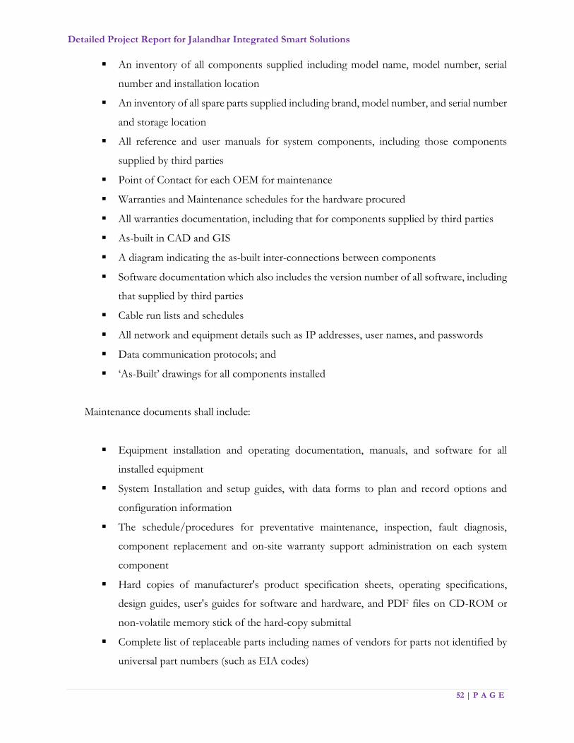
Detailed Project Report for Jalandhar Integrated Smart Solutions
52 | P A G E
An inventory of all components supplied including model name, model number, serial
number and installation location
An inventory of all spare parts supplied including brand, model number, and serial number
and storage location
All reference and user manuals for system components, including those components
supplied by third parties
Point of Contact for each OEM for maintenance
Warranties and Maintenance schedules for the hardware procured
All warranties documentation, including that for components supplied by third parties
As-built in CAD and GIS
A diagram indicating the as-built inter-connections between components
Software documentation which also includes the version number of all software, including
that supplied by third parties
Cable run lists and schedules
All network and equipment details such as IP addresses, user names, and passwords
Data communication protocols; and
‘As-Built’ drawings for all components installed
Maintenance documents shall include:
Equipment installation and operating documentation, manuals, and software for all
installed equipment
System Installation and setup guides, with data forms to plan and record options and
configuration information
The schedule/procedures for preventative maintenance, inspection, fault diagnosis,
component replacement and on-site warranty support administration on each system
component
Hard copies of manufacturer's product specification sheets, operating specifications,
design guides, user's guides for software and hardware, and PDF files on CD-ROM or
non-volatile memory stick of the hard-copy submittal
Complete list of replaceable parts including names of vendors for parts not identified by
universal part numbers (such as EIA codes)

Detailed Project Report for Jalandhar Integrated Smart Solutions
53 | P A G E
Manufacturer's product specification sheets, operating specifications, design guides, user's
guides & Permits
Contractor names and telephone number lists for all project trades
MSI shall provide Systems Manuals (SM), documentation including:
The configuration and topology of central systems hardware and software
Central systems software functions and operations
Scheduled maintenance required for the central systems; and
Database structure and data dictionary
MSI shall also provide following documents for any be-spoke software development:
Business process guides
Program flow descriptions
Data model descriptions
Sample reports
Screen formats
Frequently Asked Questions (FAQ) guides
User Manuals and technical manuals
Any other documentation required for usage of implemented solution
Documentation shall require re-issues if any change or modification will be made to the equipment
proposed. MSI may re-issue individual sheets or portions of the documentation that is affected by
the change or modification. Each re-issue or revision shall carry the same title as the original, with
a change in version number and issue date.
5.13. Operational System Acceptance
At the completion of operational acceptance test, the system shall be considered for operational
system acceptance. At the close of the work and before issue of final certificate of completion by
JSCL, the MSI shall furnish a written guarantee indemnifying JSCL against defective materials and
workmanship for a period of one (1) year after completion, which is referred to as Defect Liability
Period. The MSI shall hold himself fully responsible for reinstallation or replace free of cost to
JSCL during the Defect Liability period. MSI shall provide approved temporary replacement

Detailed Project Report for Jalandhar Integrated Smart Solutions
54 | P A G E
equipment and material such that the system remains fully functional as designed and
commissioned during repair or replacement activities at no cost to JSCL.
5.14. Comprehensive Maintenance for System and Services
It is the responsibility of the MSI to perform the comprehensive maintenance of both hardware
and software, required up-gradations in the system, expansion of the system, technical manpower,
spares management and replenishment, performance monitoring and enhancements of the
Jalandhar Smart City solutions deployed as part of this project and shall maintain service levels
that will be defined in BID DOCUMENT. All equipment and material supplied by the MSI shall
be provide with five warranty against defects of design and manufacturing and against faults and
failures associated with workmanship of MSI and its sub-contractors commencing from operation
acceptance of the system.
Any changes/upgrades to the software during comprehensive maintenance shall be subject to
comprehensive and integrated testing by MSI to ensure that changes implemented in system meets
the specified requirements and does not affect any other function of the system. Issue log for
errors and bugs identified in the solution and any change done in solution (vis-à-vis the FRS, BRS
and SRS signed off) shall be periodically submitted to JSCL. MSI shall also be responsible for
operating City website, city portal, and city application including all support, content updates and
upgrades throughout the duration of the project. Periodically, IT audits will be conducted by
JSCL/PMC third party auditor during the support period.
MSI shall ensure OEM support during Comprehensive Maintenance stage for system
performance, performance tuning, upgrades etc. MSI shall provide all support for formulation of
all policies and procedures related to System Administration, Data Base Management, applications,
archives, network management & security, back up and data recovery and archive, data
synchronization after crash. Assistance to JSCL shall be provided as needed in management of
legacy data interfaced, print spools, batch jobs, printer configuration etc.
The MSI shall also maintain the following minimum documents with respect to ICT components:
High level design of system;
Module level design of system;
System Requirement Specifications (SRS);

Detailed Project Report for Jalandhar Integrated Smart Solutions
55 | P A G E
Any other explanatory notes about system;
Traceability matrix;
Compilation environment
MSI shall also ensure Updating of following documentation of software system as applicable:
Documentation of source code;
Documentation of functional specifications;
Application documentation is updated to reflect on-going maintenance an enhancement
including FRS and SRS, in accordance with the defined standards;
User manuals and training manuals are updated to reflect on-going
changes/enhancements;
Adoption of standard practices in regards to version control and management
The communication costs (Internet charges, telephone charges, 4G/GPRS connectivity charges)
and any other incidental charges related to maintenance period shall be in the scope of the MSI
and considered to be included in the proposal submitted by the MSI for the entire project period.
Any planned and emergency changes to any component during maintenance period shall be
through a change management process. For any change, MSI shall ensure
Detailed impact analysis;
Change plan with roll back plan;
Appropriate communication on change required has taken place;
Approvals on change;
Schedules have been adjusted to minimum impact on production environment;
All associated documentation is updated post stabilization of the change;
Version control maintained for software.

Detailed Project Report for Jalandhar Integrated Smart Solutions
56 | P A G E
5.15. Support Staff Required
Three (4) types of support staff shall be provide by MSI during Operations and Maintenance
phase:
JICCC Operations Staff
Helpdesk Support Staff
Maintenance Support Staff
JICCC Operations & Helpdesk Staff
MSI shall depute JICCC Operators for maintaining the operations room on a 3-shift basis,
according to the following:
Operations Staff:
One (1) Day-Shift comprising of 4 personnel;
Other Management personnel during day shift
Project Manager
Application Integration Expert
Security expert
Intelligent Signalling & Surveillance expert
Project Management support
ICCC & IoT Expert
Network & Support Engineer
E-Governance expert
Operations Staff
Data scientists & AI Engineer
One (1) Evening-Shift comprising of 2 personnel;
One (1) Night-Shift comprising of 2 personnel
MSI shall also provide adequate support staff at Helpdesk. The support staff at Helpdesk
shall provide 24*7 services, work in a shift based system and provide full support coverage
of Helpdesk and maintain the system as per SLAs defined. At a minimum, 4 support
personnel shall be deputed at Helpdesk in first shift and two personnel in second and third
shifts during maintenance phase.

Detailed Project Report for Jalandhar Integrated Smart Solutions
57 | P A G E
IT Helpdesk:
Three (3) shifts comprising of minimum 2 personnel each for morning and evening and two for
night shift.
Maintenance Support Staff
Well-trained, efficient and effective Maintenance Support Staff shall be provided by the MSI
during the maintenance phase of the project to support JSCL operational and technical
requirements in day-to-day operations of the smart city solutions provided by MSI. The MSI
Maintenance Support staff shall address any fault originating for the Jalandhar smart city
components in the least time possible. The staff assigned shall be well qualified to attend to the
emergencies and shall be able to communicate in an effective and efficient manner. The supports
staff shall provide 24*7 services, work in a shift based system and provide full support coverage
of the Jalandhar smart city solution.
Facility Management Staff
Facilities management include but not limited to building and grounds maintenance, cleaning,
catering and vending, security, space management, utilities management etc. and associated
manpower shall also be under the scope of the MSI. At a minimum, MSI shall depute Facility
Management staff of at least 5 personnel, which shall work in a shift-based system to provide 24*7
services. Staff requirement per each shift is as per below:
Two (2) shifts comprising of 2 personnel each;
One (1) Night shift comprising of 1 personnel each.
Note: The above-mentioned staffing is indicative and MSI need to depute additional staff as per the
requirement of project.

Detailed Project Report for Jalandhar Integrated Smart Solutions
58 | P A G E
Chapter 6: Roles and Responsibility

Detailed Project Report for Jalandhar Integrated Smart Solutions
59 | P A G E
6. Roles and Responsibilities
Below are the indicative roles and responsibilities of Master System Integrator, which need
to fulfil during execution of Smart city Jalandhar Project.
1. MSI shall engage early in pro-active consultations with all the respective stakeholders
to establish a clear and comprehensive project plan, which is in line with the priorities
of all project stakeholders and the project objectives.
2. MSI shall plan the bandwidth required for operationalizing each Smart Jalandhar City
initiative until the operations and maintenance period. The bandwidth requirement
shall be analysed and procured by the MSI and make a third party agreement with
network/internet service period.
3. MSI will coordinate with the Network Service Provider, shall study the existing fibre
layout and existing network in the Jalandhar City to understand the existing technology
adopted in each of the following areas (not limited to):
OFC/Network/Wi-Fi
Surveillance Infrastructure – CCTV Cameras, Data Communication,
Monitoring, Control Room and Infrastructure
Any other Smart City initiatives envisaged for Jalandhar
4. MSI shall assess existing infrastructure’s current ability to support the entire solution
and integrate the same with the solution wherever applicable and possible
5. MSI shall be responsible for planning and designing of the access network architecture
(access controllers, backhaul connectivity, routers, switches, etc.) to meet the technical,
capacity and service requirements for all smart Jalandhar City initiatives
6. MSI shall judiciously evaluate the resources and time planned for undertaking the
current state assessment, given the overall timelines and milestones of the project.
7. Validate / Assess the re-use of the existing infrastructure if any with site identified by
JSCL
8. Supply, Installation, and Commissioning of entire solution at all the locations
9. MSI shall Install and commission connectivity across all designated locations
10. MSI shall establish high availability, reliability and redundancy of the all the
elements/components to meet the Service Level requirements which will be defined
in BID DOCUMENT
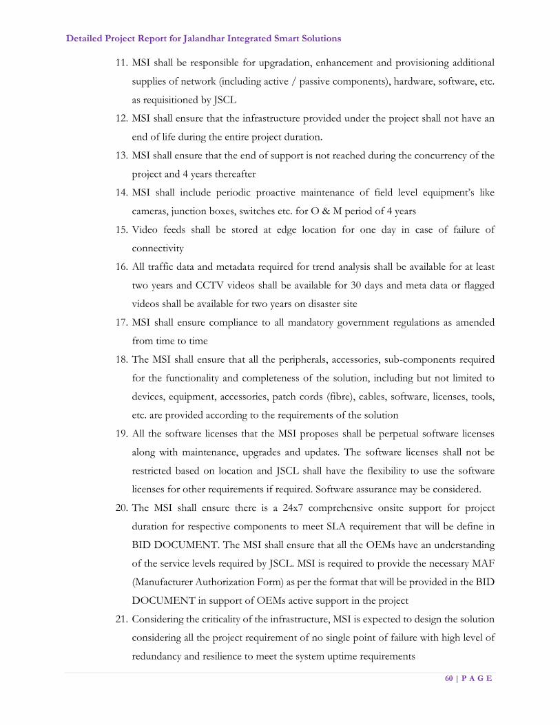
Detailed Project Report for Jalandhar Integrated Smart Solutions
60 | P A G E
11. MSI shall be responsible for upgradation, enhancement and provisioning additional
supplies of network (including active / passive components), hardware, software, etc.
as requisitioned by JSCL
12. MSI shall ensure that the infrastructure provided under the project shall not have an
end of life during the entire project duration.
13. MSI shall ensure that the end of support is not reached during the concurrency of the
project and 4 years thereafter
14. MSI shall include periodic proactive maintenance of field level equipment’s like
cameras, junction boxes, switches etc. for O & M period of 4 years
15. Video feeds shall be stored at edge location for one day in case of failure of
connectivity
16. All traffic data and metadata required for trend analysis shall be available for at least
two years and CCTV videos shall be available for 30 days and meta data or flagged
videos shall be available for two years on disaster site
17. MSI shall ensure compliance to all mandatory government regulations as amended
from time to time
18. The MSI shall ensure that all the peripherals, accessories, sub-components required
for the functionality and completeness of the solution, including but not limited to
devices, equipment, accessories, patch cords (fibre), cables, software, licenses, tools,
etc. are provided according to the requirements of the solution
19. All the software licenses that the MSI proposes shall be perpetual software licenses
along with maintenance, upgrades and updates. The software licenses shall not be
restricted based on location and JSCL shall have the flexibility to use the software
licenses for other requirements if required. Software assurance may be considered.
20. The MSI shall ensure there is a 24x7 comprehensive onsite support for project
duration for respective components to meet SLA requirement that will be define in
BID DOCUMENT. The MSI shall ensure that all the OEMs have an understanding
of the service levels required by JSCL. MSI is required to provide the necessary MAF
(Manufacturer Authorization Form) as per the format that will be provided in the BID
DOCUMENT in support of OEMs active support in the project
21. Considering the criticality of the infrastructure, MSI is expected to design the solution
considering all the project requirement of no single point of failure with high level of
redundancy and resilience to meet the system uptime requirements

Detailed Project Report for Jalandhar Integrated Smart Solutions
61 | P A G E
22. MSI shall be responsible for periodic updates & upgrades of all equipment, cabling
and connectivity provided at all locations.
23. MSI shall be responsible for setting up / building / renovating the necessary physical
infrastructure including provisioning for network, power, rack, etc. at all the locations
24. MSI is expected to provide following services, including but not limited to:
i. Provisioning hardware and network components of the solution, in line with
the proposed JSCL requirements
ii. Size and propose network devices like Router, switches, security equipment
including firewalls, IPS / IDS, routers, etc. as per the location requirements
with the required components/modules, considering redundancy and load
balancing
iii. Size and provision the WAN bandwidth requirements across all locations
considering the application performance, data transfer, DR and other
requirements for smart Jalandhar City initiatives
iv. Size and provision the internet connectivity for Service Provider network and
Network Backbone
v. Size and provision for bandwidth as a service for operations of JICCC
vi. Liaise with service providers for commissioning and maintenance of the links
vii. Furnish a schedule of delivery of all IT/Non-IT Infrastructure items
viii. JSCL may at its sole discretion evaluate the hardware sizing document
proposed by the MSI. The. MSI needs to provide necessary explanation for
sizing to JSCL
ix. Complete hardware sizing for the scope with provision for upgrade
x. Specifying the number and configuration of the racks (size, power, etc.) that
shall be required at all the locations.
xi. The MSI shall provide for all required features like support for multiple routing
protocols, congestion management mechanisms and Quality of Service
support
xii. The MSI shall ensure that all active equipment (components) are Simple
Network Management Protocol (SNMP) V3 compliant and are available for
maintenance/management through SNMP from the date of installation by a
Network Monitoring System

Detailed Project Report for Jalandhar Integrated Smart Solutions
62 | P A G E
25. MSI shall directly interact with electricity board for provision of mains power supply
at all desired locations for any Field Infrastructure solution. The Jalandhar Smart City
shall facilitate, if any documentation is required from its side.
26. All existing road signs, which are likely to be effect by the works, are to be carefully
take down and stored. Signs to be re-erected shall be clean, provided with new fixings
where necessary and the posts re-painted in accordance with Jalandhar Smart City
guidelines. Road signs, street nameplate etc. damaged by the MSI during their
operation shall be repaired or replaced at the MSI’s cost.
27. It’s the responsibility of MSI to integrate the ICCC system with the other application
developed by / for Jalandhar Govt. department post taking required approval from
authorized authority
28. The infrastructure of existing Traffic signal systems or any other filed Infrastructure
including the poles, cantilevers, aspects, controllers and cabling and associated
mountings and civil infrastructure as required based on detailed study may need to be
dismantled (where ever applicable) and replaced with the new systems proposed shall
be done by MSI. The dismantled infrastructure shall be delivered at the Jalandhar
Smart City designated location without damage, at no extra cost.
29. Prior to starting the site clearance, the MSI shall carry out survey of field locations.
The Jalandhar Smart City shall be fully informed of the results of the survey and the
amount and extent of the demolition and site clearance shall be agreed with JSCL.
30. Lightning Proof Measures:
a. The MSI shall comply with lightning-protection and anti –interference
measures for system structure, equipment type selection, equipment earthing,
power, signal cables laying.
b. Corresponding lightning arrester shall be erect for the entrance cables of
power line, video line, data transmission cables. All crates shall have firm,
durable shell. Shell shall have dustproof, antifouling, waterproof functions;
capable to bear certain mechanical external force.
c. Signal separation of low and high frequency; equipment protective field shall
be connected with their own public equal power bodies; small size/equipment
signal lightning arrester shall be erected before the earthing.
d. The Internal Surge Protection Device for Data Line Protection shall be select
as per zone of protection described in IEC 62305, 61643-11/12/21, 60364-
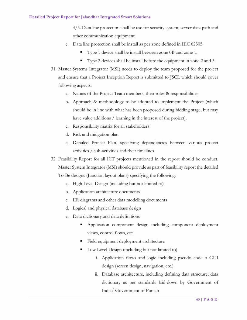
Detailed Project Report for Jalandhar Integrated Smart Solutions
63 | P A G E
4/5. Data line protection shall be use for security system, server data path and
other communication equipment.
e. Data line protection shall be install as per zone defined in IEC 62305.
Type 1 device shall be install between zone 0B and zone 1.
Type 2 devices shall be install before the equipment in zone 2 and 3.
31. Master Systems Integrator (MSI) needs to deploy the team proposed for the project
and ensure that a Project Inception Report is submitted to JSCL which should cover
following aspects:
a. Names of the Project Team members, their roles & responsibilities
b. Approach & methodology to be adopted to implement the Project (which
should be in line with what has been proposed during bidding stage, but may
have value additions / learning in the interest of the project).
c. Responsibility matrix for all stakeholders
d. Risk and mitigation plan
e. Detailed Project Plan, specifying dependencies between various project
activities / sub-activities and their timelines.
32. Feasibility Report for all ICT projects mentioned in the report should be conduct.
Master System Integrator (MSI) should provide as part of feasibility report the detailed
To-Be designs (Junction layout plans) specifying the following:
a. High Level Design (including but not limited to)
b. Application architecture documents
c. ER diagrams and other data modelling documents
d. Logical and physical database design
e. Data dictionary and data definitions
Application component design including component deployment
views, control flows, etc.
Field equipment deployment architecture
Low Level Design (including but not limited to)
i. Application flows and logic including pseudo code o GUI
design (screen design, navigation, etc.)
ii. Database architecture, including defining data structure, data
dictionary as per standards laid-down by Government of
India/ Government of Punjab
Detailed Project Report for Jalandhar Integrated Smart Solutions
64 | P A G E
Location of all field systems and components proposed at the
junctions/other locations on GIS Map
Height and foundation of Traffic Signals and Standard Poles for
Pedestrian signals.
Height and foundation of Poles, cantilevers, gantry and other
mounting structures for other field devices
Location of Junction Box
- Location of PoP (Pump Out Plug)
Electrical power provisioning

Detailed Project Report for Jalandhar Integrated Smart Solutions
65 | P A G E
Chapter 7: Scope of Project

Detailed Project Report for Jalandhar Integrated Smart Solutions
66 | P A G E
7. Scope of Project
The location for JICCC is yet need to be finalize. A common Jalandhar Integrated Command
Control Centre (JICCC) shall be implement in around ~ 5000 Sq. Ft area. The location where
Viewing centres/ Video feeds as required shall finalized at the times of system study conducted
by MSI.
Note: Smart city office & Jalandhar Traffic police office will be collocated with JICCC
The Floor Plan of JICCC and other details will be provided in BID DOCUMENT. The indicative
details of sections and the office space which will be provided to respective section resource in
JICCC is mentioned below
SECTIONS DETAILS AREA AREA
(sq.mt.) (sq. ft.)
Center - In Charge 12 sq.mt. per cubicle
10 107.9
JICCC Manager/Operations Manager 12 sq.mt. per cubicle
6 64.74
System Administrator 12 sq.mt. per cubicle
6 64.74
Helpdesk Manager 12 sq.mt. per cubicle
6 64.74
ICCC Solution Architect 12 sq.mt. per cubicle
6 64.74
GIS Expert 12 sq.mt. per cubicle
6 64.74
IT Manager 12 sq.mt. per cubicle
6 64.74
Analytics Center - Data scientists e-Challan(2), Forensic
12 sq.mt. per cubicle
6 64.74
Facility Staff 8 86.32
Command & Control Room 16 workstations, 7 X 3 = 21 screens, 50" on video wall
130 1402.7
Data Center & Network Opera rations Center
16 172.64
Conference Room Conference for 20 people - 2
30 323.7
IT Team Room 8 workstations 60 647.4

Detailed Project Report for Jalandhar Integrated Smart Solutions
67 | P A G E
IT Store 12 129.48
Helpdesk Team Room 10 workstations 80 863.2
Rest Rooms for Male and Female & Drinking Water
1 W/C per 25 males, 1 W/C per 15 females, 1 urinal for 7-20 persons, 2 for 21-45 person
20 215.8
Pantry 12 129.48
Power backup room 10 107.9
Reception, Waiting lobby, Stair case 37 399.23
TOTAL AREA REQUIREMENT (INDICATIVE)
467 5038.93
7.1. Jalandhar Integrated Command Control Centre (JICCC)
With a view of enabling varied and respective stakeholders to operate specified Smart City
Components, it is proposed to build Jalandhar Integrated Command Control Centre (JICCC),
which will cater to the City Operations, City Surveillance, Emergency Response System, Helpdesk
and the components.
While the entire Smart City initiative to build around various components of smart interventions
for different citizen centric services and facilitating administration, Jalandhar Integrated
Command Control Centre or JICCC brings all the outputs onto a single platform and give an
integrated view. This works as a monitoring system that helps in decision-making process a lot
simpler and comprehensive. It acts as support mechanism to the city administration/authorities
in their daily routine activities as well as during exigency situations. This dynamic response to
situations, both pre-active and re-active will truly make the city operations “SMART”.
Apprehending the huge volume of information generation with the help of Pan City ICT
infrastructure, a centralized command control center is envisaged. All the smart solutions,
network components will converge at the centralized command control center. Jalandhar
Integrated Command Control Centre (JICCC) involves leveraging on the information provided
by various departments and providing a comprehensive response mechanism for the day-to-day
challenges across the city. JICCC shall be a fully integrated, web-enabled solution that provides
seamless incident -response management, collaboration and geo-spatial display. Additional third
party modules can be integrated as per solution requirements.
Detailed Project Report for Jalandhar Integrated Smart Solutions
68 | P A G E
The JICCC shall facilitate the viewing and controlling mechanism for the selected field
locations in a fully automated environment for optimized monitoring, regulation and
enforcement of services. The JICCC shall be accessible by operators and concerned
authorized entities with necessary role based authentication credentials
Activities at the JICCC will comprise of monitoring services, incident management and
response as per the Standard Operating Procedures (SOPs) with defined escalation
procedures.
The JICCC will manage and monitor entire the project and services. All the information and
data collected through various components of the smart city project will be viewable through
a centralized Application.
JICCC will comprise of a centralized dashboard for entire smart city project for the reporting
and viewing of all the project components and key performance indicators of systems such
as CCTV Camera Surveillance System, Intelligent Signalling, Environmental Monitoring etc.
through a single interface.
JICCC will act as the centralized monitoring and decision making hub for managing Smart
Applications and related Infrastructure project activities. Various smart elements will be able
to use the data and intelligence gathered from operations of other elements so that civic
services are delivered lot more efficiently and in an informed fashion.
The benefits of the JICCC will be measured from two perspectives:
In times of disaster – This will improve the response time, coordination amongst
various agencies and faster restoration of services post disaster.
In day-to-day non-emergency scenarios – This will improve the response time of
Municipal Corporation towards citizen complaints, which in turn will lead to citizens
using the system more frequently. This will also enable the various departments to
offer better services to citizens including, utilities, security, traffic, etc.
7.1.1. Various Components of JICCC
The Integrated Command and Control Centre shall comprise of:
a. Video Wall & Controller system
b. Data Centre
c. City Operations Platform

Detailed Project Report for Jalandhar Integrated Smart Solutions
69 | P A G E
d. Furniture, Fixtures, Operator Workstation and accessories
e. Conference / Situation Room
f. Integrated Dashboard
g. Standard Operating Procedure Tool
h. Helpdesk, Technical and Operations Staff
The Jalandhar Integrated Command Control Centre (JICCC) will be the nodal point of availability
of all online data and information related to smart services. It will be a full-fledged system
equipped with all the operational rights to its specified users. This will have integration with
various components with data feed view and sharing. It will also have management console to
perform all the operations.
The Component Modules
The scope will entail design, development, installation, operation and maintenance of the
following components JICCC:
Centralized Command Control Room
Data Center to cater to all Smart components of Smart City
City Surveillance
ITMS
Environmental sensors
GIS Integration
Mobile Application for Smart Solutions
Disaster Management
Data Analytics Center
Helpdesk
Viewing Centres
Viewing centres shall have the following:
LED screens for viewing and controlling video feeds
Work station, Connectivity to Central Integrated Command Control Center
Partition for Viewing center & Biometric access control with air conditioner as applicable

Detailed Project Report for Jalandhar Integrated Smart Solutions
70 | P A G E
Component Architecture
The component architecture of JICCC is mentioned below along with logical diagram.
1. Field IT Infrastructure Layer
2. Network Layer
3. Data Center Layer
4. Application Layer
5. Integration Layer
6. Command and Communication Center Layer
7. Security Layer
This component architecture is indicative in nature and bring clarity on the overall scope of
project and its intended use. The MSI is expect to carry out the detail requirement analysis and
finalize the technical architecture in consultation with JSCL and its consultants.
Figure: Logical diagram of JICCC

Detailed Project Report for Jalandhar Integrated Smart Solutions
71 | P A G E
1. Field IT Infrastructure Layer –The sensor layer will help the city administration gather
information about the ambient city conditions or capture information from the edge level
devices like GPS devices, cameras, etc. MSI is expected to deploy multiple environmental
sensors across the city, to measure ambient conditions such as light intensity, temperature, air
pollution, noise pollution and humidity, etc. The output field devices layer will contain display
devices or bi-directional (input & output) devices connected to the network, which will be
used by citizens to consume - and for administrators to provide actionable information. Such
field devices include digital messaging boards, environmental data displays, PA systems,
surveillance cameras among others.
2. Network Layer – The secured network layer will serve as the backbone for the project and
provide connectivity to gather data from sensors and communicate messages to display
devices and actuators. The MSI will size the bandwidth required for the overall solution, and
supply and install the edge devices to utilize the network.
3. Data Center Layer – The data center layer will house centralized computing power required
to store, process and analyse the data to decipher actionable information. This layer includes
servers, storage, ancillary network equipment elements, security devices and corresponding
management tools. A disaster recovery site, which includes servers, storage, network
equipment and security management systems, will be used in case of fall-back mechanism for
the data center.
4. Application Layer – The applications layer will include applications that interface and
control the street infrastructure, enterprise management system to monitor and manage all IT
infrastructure and street infrastructure deployed in the city, and surveillance applications.
5. Integration Layer – While aspects of ambient conditions within the city will be gathered
through various sensors deployed as a part of the solution, some city specific data will come
from other government and non-government agencies. It is through the integration layer –
that data will be exchanged to and from the under lying architecture components and other
data from system developed by government (such as police department, meteorological

Detailed Project Report for Jalandhar Integrated Smart Solutions
72 | P A G E
department, street lights department, water department, irrigation department, transport
organizations within Jalandhar, etc.) and non-government agencies.
6. Command and Communication Center Layer – The command center will enable citizens
and administrators alike to get a holistic view of city conditions, and make informed decisions.
7. Security Layer – As ambient conditions, actuators and display devices are now connected
through a network, security of the entire system becomes of paramount significance and the
master system integrator (MSI) will have to provide Infrastructure security, Network security,
Identity and Access Management, and Application security.
7.1.2. General Requirements
MSI shall be responsible for compliance with all local standards and certifications,
including building, electrical and occupational requirements
MSI shall integrate JICCC with various other city systems and infrastructures. MSI shall
coordinate with all the stakeholders of these city systems for integration purposes
MSI shall be responsible for setting up the required software platform and interfacing
JICCC with other city components as applicable
Define SOPs with JSCL or its representative for the operations to ensure that JICCC
systems are configured to support the operational procedures
Creation of KPIs and dashboards as per the requirement
Build and certify JICCC as per ISO 27001:2011 standards.
7.1.3. Key Performance Indicators
1. The vision of the Jalandhar Integrated Command Control Center (JICCC) is to have an
integrated view of all the smart initiatives undertaken by JSCL with the focus to serve as a
decision support engine for city administrators for day-to-day operations or during exigency
situations. This dynamic response to situations, both pre-active and re-active will truly make
the city operations “SMART”.
Detailed Project Report for Jalandhar Integrated Smart Solutions
73 | P A G E
2. JICCC involves leveraging the information provided by various departments and providing a
comprehensive response mechanism for the day-to-day challenges across the city. JICCC shall
be a fully integrated, Web-Based Server integrated with web based access/services, solution
that provides seamless incident – response management, collaboration and geo-spatial display.
Additional third party modules may be integrated as per solution requirements.
3. JICCC shall facilitate the viewing and controlling mechanism for the selected field locations
in a fully automated environment for optimized monitoring, regulation and enforcement of
services. The smart city operations center shall be accessible by operators and concerned
authorized entities with necessary authentication credentials.
4. Various smart elements are able to use the data and intelligence gathered from operations of
other elements so that civic services are delivered a lot more efficiently and in an informed
fashion.
5. JICCC will provide 24*7 City Surveillance System for effective management of the city.
6. JICCC shall leverage state of the art technology to effectively manage Road Traffic
7. JICCC should be able to integrate with various utility systems such as ITMS, Emergency
Response System, Helpdesk etc.
The Technology Principles
The following principles must be adopted during designing and development of the JICCC:
Requirements-based Change – Changes to technology and applications are made only in
response to changes in processes / service needs.
Controlled Technological Diversity – Technological diversity is controlled to minimize
the costs of maintaining expertise and connectivity between multiple processing
environments.
Adherence to Standards – Software and hardware should conform to all mandatory and
necessary standards.
Detailed Project Report for Jalandhar Integrated Smart Solutions
74 | P A G E
Processes
The JICCC is the centralized component that holds all the smart city projects together and gives
the decision makers a complete picture of the issues currently being face by different stakeholders.
The supporting process that are to be designed and executed within the JICCC are:
a. Definition of role-based access mechanism
b. Definition, logging and periodic review of standard operating procedures
c. System health monitoring for each of the smart city components integrated with JICCC
d. Periodic review of risks identified under monitoring and mitigation plan
e. System backup and archival process
f. Audits and (Re) certifications
Types of Operations
A. Normal Operations
Under normal operating conditions, various members of Operations team shall coordinate their
activities and exchange information through voice and data communications systems about the
equipment / facilities under their supervision to facilitate a safe and secure arrangement
throughout the entire Jalandhar City. Under the normal conditions, the operations team shall
continuously supervise the main assets and identify any fault, anywhere in system promptly.
Operation team shall isolate faulty elements and operate the system in a manner to arrange
alternatives wherever appropriate, alternative is possible (element redundancy, rerouting of
services, alternate feeding path etc.). Faulty elements are further referred to appropriate team for
respective corrective action. The JICCC Framework shall be able to enable faster isolation of
faulty elements & identification & implementation of inbuilt alternatives in system.
B. Degraded Operation
Degraded modes of operations occur when certain systems fail to meet the levels of service
expectation. In such scenario, the applicable Standard Operating Procedure (SOP) will be
followed.

Detailed Project Report for Jalandhar Integrated Smart Solutions
75 | P A G E
For ex: Various failures in power installation may affect the distribution of power in various
sectors of the Jalandhar City. Load shedding need to be planned looking at many aspects, few of
the incidents/situations may include Student Exams, Hospitals and Industries.
C. Emergency Operation
In a Smart City, the emergencies need to be averted beforehand. Emergency operations are
enforced in case of an unforeseen or abnormal situation, when it is not possible to carry on the
services. An emergency or disaster is a sudden or calamity leading to deep distress affecting men
and machinery. Many of the accidents / incidents like an act of vandalism, terrorist attack, an
accidental fire, critical system failure, force majeure, etc. may lead to crisis / disaster. In cases of
disasters, the main objective is to disperse the affected persons, as early as possible, from the
affected site of occurrence and avoid loss of life and properties. Management of such situation
requires sharing of clear and accurate information and necessary actions shall be initiate without
any delay to ensure the restoration of normalcy.
This requires seamless & timely sharing of information amongst multi-disciplines (viz.
Traffic, Parking, Helplines, Smart Lights, Signal & Telecommunication, etc.) involved in
Operations
Necessitates that appropriate actions are initiated without any delay and the situation is
tackled in the most appropriate and efficient manner, so that distress is relieved
expeditiously.
Thus, for effective management of such scenarios, it is preferable to have visibility and ability to
manage critical disciplines at one place. The JICCC framework shall support Automation of Disaster
Management Procedure. The CCTV Cameras throughout the City and analytical tools would perform
the emergency operations during such situations.
7.1.4. Product Licenses
All products and licenses procured shall be on Jalandhar Smart City Limited. Copy of the license terms
and conditions has to be submitted to ASCL during trial run. All COTS software licenses shall be
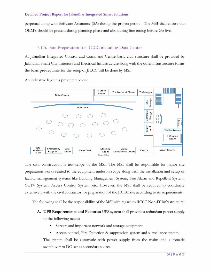
Detailed Project Report for Jalandhar Integrated Smart Solutions
76 | P A G E
perpetual along with Software Assurance (SA) during the project period. The MSI shall ensure that
OEM’s should be present during planning phase and also during fine tuning before Go-live.
7.1.5. Site Preparation for JICCC including Data Center
At Jalandhar Integrated Control and Command Centre basic civil structure shall be provided by
Jalandhar Smart City. Interiors and Electrical Infrastructure along with the other infrastructure forms
the basic pre-requisite for the setup of JICCC will be done by MSI.
An indicative layout is presented below:
The civil construction is not scope of the MSI. The MSI shall be responsible for minor site
preparation works related to the equipment under its scope along with the installation and setup of
facility management systems like Building Management System, Fire Alarm and Repellent System,
CCTV System, Access Control System, etc. However, the MSI shall be required to coordinate
extensively with the civil contractor for preparation of the JICCC site according to its requirements.
The following shall be the responsibility of the MSI with regard to JICCC Non-IT Infrastructure:
A. UPS Requirements and Features: UPS system shall provide a redundant power supply
to the following needs:
Servers and important network and storage equipment
Access control, Fire Detection & suppression system and surveillance system
The system shall be automatic with power supply from the mains and automatic
switchover to DG set as secondary source.

Detailed Project Report for Jalandhar Integrated Smart Solutions
77 | P A G E
B. Diesel Generator Set: MSI has to specify the technical specifications based on the
requirement. The MSI shall be responsible for regular operations and maintenance of the
DG set. The MSI shall be responsible for but not limited to:
Fuel
Preventive maintenance
Corrective maintenance
AMC, if any
Replacement of any parts etc.
C. Fire Detection and Suppression System: The facility shall be equipped with adequate
and advanced Fire Detection and Suppression system. The system shall raise an alarm in
the event of smoke detection. The system shall have proper signage, response indicators
and hooters in case of an emergency. The system shall be based as per NFPA standards.
D. Building Management System: Building Management System shall be implemented for
effective monitoring, management, control and integration of various building systems
such as HVAC, lighting, electrical, fire detection and suppression system, CCTV system,
Access Control System etc. over a single platform. BMS shall perform various functions
such as data collection and archival, alarm and event management, trending, reports and
MIS generation, preventive maintenance etc.
E. Access Control System: The Biometric/Access card based Access Control System shall
be deployed with the objective of allowing entry and exit to and from the premises to
authorized personnel only with appropriate door locks and controller assemble. The
system deployed shall be based on proximity as well as biometric technology for critical
areas and proximity technology for non-critical areas.
F. CCTV System: The MSI shall provide CCTV system within the Data center and JICCC
on 24X7 bases. All-important areas of the Data center, JICCC along with the non-critical
areas like locations for DG sets, entry exit of Jalandhar Integrated Command Control
Center (JICCC), Entry and Exit of building premises need to be under constant video
surveillance. Monitoring cameras shall be installed strategically to cover all the critical
areas of all the respective locations.
G. Water Leak Detection System: The Water Leak Detection System shall be install to
detect any seepage of water into the critical area and alert the security control room for
such leakage. It shall consist of water leak detection cable and alarm module. The cable
shall be installed in the ceiling and floor areas around the periphery.

Detailed Project Report for Jalandhar Integrated Smart Solutions
78 | P A G E
H. Rodent Repellent: The entry of rodents and other unwanted pests shall be controlled
using non-chemical, non-toxic devices. Ultrasonic pest repellents shall be provided in the
false flooring and ceiling to repel the pests without killing them. However, the MSI shall
conduct periodic pest control using chemical spray once in a quarter as a contingency
measure to effectively fight pests.
7.1.6. Functional requirements
Integrated Command Control Centre
The following are the indicative functional requirements of JICCC required for smart city
operations. MSI is expect to use all the functionalities of IOT platform/City Operations Platform
for holistic management of Smart city applications and integrate applications.
Jalandhar Integrated Command & Control Center (JICCC)
Sl. No Minimum Specifications
1 JICCC shall provide a holistic and real time view of all city operations on a video wall along with individual views on operator workstations
2 JICCC shall enable monitoring, control and automation of various city operations in order to ease and organise city operations.
3 JICCC shall enable system and cross system analytics through smart city platform in order to make city operations intelligent
4 JICCC shall leverage information provided by multiple city systems in order to provide an integrated, seamless, proactive and comprehensive response mechanism for day-to-day city operations and challenges
5 JICCC shall provide real time dashboards, visualizations, KPIs, historical trending, analytics and other intelligent features to facilitate city operations analysis by city administrators.
6 JICCC shall provide alarm features for immediate notification to city administrators in case critical event occurs in the city
7 The Digital Content Management System (DCMS) provided as part of JICCC will manage and drive all visual content to the various display devices, including the video display wall. All city systems will display content through the DCMS
8 The operators will also manage and control various systems, and dispatch to system maintenance staff. They will be responsible for monitoring and managing all integrated city systems out of the JICCC.
9 All workstation units of the operator shall be installed at the central rack rooms so that space at the JICCC operator desks can be optimised as applicable.
10 Direct connections and data from devices / systems shall include real-time city systems data, KPIs and video feeds from CCTV cameras.

Detailed Project Report for Jalandhar Integrated Smart Solutions
79 | P A G E
Sl. No Minimum Specifications
Facilities Management and Building Management Systems (BMS)
11 Interface with the Building Management Systems (BMS) installed in JICCC for monitoring and control of all the building systems and parameters available through the BMS.
12 Interface with all the BMS or IP enabled fire alarm system for monitoring of essential parameters
13 Log calls / jobs on the helpdesk database utilizing helpdesk software (inquiries may be received by telephone, facsimile, email or in person).
14 Allocate and dispatch work orders to directly employ (or subcontracted) maintenance team
15 Take ownership of the Preventative Maintenance (PM) schedule and track reactive maintenance (RM) service requests.
16 Track progress of PM and RM service requests against pre-determined KPIs
17 Report back to JSCL and contract staff on progress of each PM and RM service request and close out service requests when completed
18 Maintain asset information
19 Update site specific facilities management files and other documentation for helpdesk compliance
20 Dispatch of emergency services
City Security
21 Accurately and promptly observe, monitor and operate closed circuit television (CCTV) cameras and related equipment, and, where necessary direct Police Officers to real time incidents
22 To identify, report, and record anything suspicious, in line with JICCC procedures
23 To operate the cameras and equipment effectively ensuring that best possible evidential quality images are recorded
24 To ensure all equipment is functioning correctly, carry out equipment checks as required and report all faults to relevant personnel, carry out basic non-technical system maintenance as required
Traffic Management
25 Recognize, identify and monitor the infracting vehicles in real-time / off-line mode for various violations at junctions and in streets
26 The system shall have the ANPR Non-intrusive modes of enforcement on traffic light violation and Speed
27 The system at the JICCC should be integrated with the E-Challan system to enable E-Challan generation, payment and billing process
28 Public Address (PA) System is disseminate the information to the citizen particularly emergency situation messages to reach quickly
29 The system should be able to integrate other network PA systems or third party application systems where the alerts are generated to broadcast messages at JICCC
30 The system should be able to generate various statistics, reports & MIS from time to time at JICCC.
31 Variable Message Sign (VaMS) board shall provide feedback to the JICCC on the VaMS status of Active / Inactive.
Detailed Project Report for Jalandhar Integrated Smart Solutions
80 | P A G E
Sl. No Minimum Specifications
32 The system should maintain the history of messages archived for future reference and analysis
33 The ATCS & ATCC system shall provide multiple interfaces to share the data seamlessly to different sub systems e.g. Signalling system to configure and determine the traffic signal duration based on the traffic congestion, weather conditions, traffic pattern and other factors
34 The system at the JICCC shall feed the traffic density information to the associated junctions of critical junction subsystem to determine the expected traffic from its previous junction and traffic signal duration
Environmental Sensors
35 Monitor key inputs from pollution sensors, noise sensors, particle sensors, etc.
36 Create awareness within the city based on dynamic inputs received from sensors and display output to various interfaces including city application, multi-services digital kiosks and Digital Display Screen (DDS).
37 Inputs to various regulations and permissions as needed in terms of carbon content, and content of other particles and gases in around Jalandhar
Smart Mobility & Vehicle Location Systems
38 CAD/AVL System: Vehicle location monitoring for the following vehicles shall be done at JICCC:
City Buses (Phase II)
Municipal Vehicles
Fire Engines
Ambulances
Police Vans
Mobile Surveillance Vehicles (Phase II)
Any other vehicle owned by JSCL (Phase II)
39 Complete operations management of the Municipal and Emergency Vehicles shall be provided from JICCC / Emergency Response Control Centre
Common Operations Platform (COP)
Sl. No Parameter Minimum Specifications
1 Solution & Platform The Command & Control solution should be implement
and complied to the industry open standards based
Commercial-of-the-shelf (COTS) products.
The solution should be network and protocol agonistic
and provide option to connect legacy system through
APIs with either read, write or both options. It should

Detailed Project Report for Jalandhar Integrated Smart Solutions
81 | P A G E
Sl. No Parameter Minimum Specifications
connect diverse on premise and/or cloud platforms and
makes it easy to exchange data and services between them.
The system shall allow seamless integration with all of the
department's existing and future initiatives (e.g. open
source intelligence, situation management, war room,
etc.).
System must provide a comprehensive API (Application
Programming Interface) or SDK Software Development
Kit) to allow interfacing and integration with existing
systems.
Software (Application, Database and any other) must not
be restrict by the license terms of the OEM from scaling
out on unlimited number of cores and servers for future
expansion.
The platform should be able to normalize the data coming
from different devices of same type (i.e. different lighting
sensors from different OEMs, different energy meters
from different OEMs etc.) and provide secure access to
that data using data API(s) to application developers.
The platform should be able to integrate with any type of
sensor platform being use for the urban services
irrespective of the technology used.
Must have built-in fault tolerance, load balancing and high
availability & must be certify by the OEM.
The platform shall provide replay of all the events
occurred based on user specified criteria.
Platform should support on the fly deployment of
Sensors. Platform shall have the ability to add / remove
sensors including new vendor types without a need for
shutdown.

Detailed Project Report for Jalandhar Integrated Smart Solutions
82 | P A G E
Sl. No Parameter Minimum Specifications
Platform should support Cross collaboration APIs
thereby enabling contextual information and correlation
across domains and verticals.
The software should be able to combine data from various
sources and present it as different views tailored to
different operator’s needs. Common Operational Picture
should comprise of a comprehensive view of the events as
on a specific date and time which should include but not
be limited to manual tasks assignment and their status,
Agencies involved, Resources deployed, Timeline view of
the situation.
Should provide tools for users to collaborate in real-time
using instant messaging features. Provide the ability to
search/locate resources based on name, department, role,
geography, skill etc. for rapidly assembling a team, across
department, divisions and agency boundaries, during
emergency. Provide the capability to Invite - Using
information provided during the location of those
individuals or roles, invite them to collaborate and to share
valuable information. Provide a single web based
dashboard to send notifications to target audiences using
multiple communication methods including voice‐based
notification on PSTN/Cellular, SMS, Voice mail, and E‐
mail.
The system should provide a facility to see alarms and
KPI’s filtered by day, week, month, year or any specific
date range. The system should be able to filter the
information based on at least the Event information
Resources information, Agency type, Tasks and Criticality
or priority

Detailed Project Report for Jalandhar Integrated Smart Solutions
83 | P A G E
Sl. No Parameter Minimum Specifications
2 Command and
Control Center
Components
Web Server to manage client requests. Client/User should
be provided with web-based, one-stop portals to event
information, overall status, and details.
The User Interface (UI) to present customized
information in various preconfigured views in common
formats. All information to be displayed through easy-to-
use dashboards.
Application Server to provide a set of services for
accessing and visualizing data. Should be able to import
data from disparate external sources, such as databases
and files. It should provide the contacts and instant
messaging service to enable effective, real-time
communication. It should provide business-monitoring
service to monitor incoming data records to generate key
performance indicators. It should also provide the users
to view key performance indicators, standard operating
procedures, notifications, and reports, spatial-temporal
data on a geospatial map, or view specific details that
represent a city road, building or an area either on a
location map, or in a list view. The application server
should provide security services that ensure only
authorized users and groups can access data. Analytics
functionality can be part of application server or separate
server
3 Industry Standards
for the Command
and Control Center
The solution should adhere to the industry standards for
interoperability, data representation & exchange,
aggregation, virtualization and flexibility. IT Infrastructure
Library (ITIL) V3 or above standards for Standard
Operations Plan & Resource Management
Geo Spatial Standards like GML & KML etc.
Business Process Model and Notation (BPMN) or
equivalent for KPI Monitoring.
Detailed Project Report for Jalandhar Integrated Smart Solutions
84 | P A G E
Sl. No Parameter Minimum Specifications
4 Availability,
Scalability,
Performance and
Usability
The solution system shall be highly available platform.
The system shall be very tolerant to losses or reduction of
communication such that the system shall recover
gracefully from such incidents, with no human interaction
required.
Should have a high performance and high availability
architecture.
Shall be flexible, modular and tolerant to failures/errors
and able to exchange information with other systems
The system must have an open architecture such that
additional systems when added can be integrate with CCA
without upgrades or disruption to other interfaces.
The communications use standard components that are
widely available.
Should allow scalability and flexibility to include more
applications / solutions in the future
The server shall refresh system GUI within 1 second of an
incident trigger requiring a change of state in the
information in the database.
The server hardware shall be based on high availability,
fault tolerant design and capable of operating in mirrored
server configuration.
The system shall have a resilient processing architecture
such that failure of a single component does not affect
entire common operations platform/ application.
The system shall be able to operate at network bandwidth
down to a minimum of 1 mbps.
The system shall be able to operate at network latencies as
long as 2 seconds.
5 Convergence of Multiple feeds/
services
System need to have provision that integrates various
services and be able to monitor them and operate them.

Detailed Project Report for Jalandhar Integrated Smart Solutions
85 | P A G E
Sl. No Parameter Minimum Specifications
The solution should provide option to integrate existing
deployed solution by City and need to provide scalability
option to implement new use cases.
System should have capability to source data from various
systems implemented in the city (being implemented as
part of this project or other projects) to create actionable
intelligence
6 Integrated User Specific &
Customizable Dashboard
Should provide integrated dashboard with an easy to
navigate user interface for managing profiles, groups,
message templates, communications, tracking receipts and
compliance
Collects major information from other integrated City
sensors/platforms.
Should allow different inputs beyond cameras, such as,
User desktop screens, web page, and other external
devices for rich screen layout
Multi-displays configurations
Support for GIS tool which allows easy map editing for
wide area monitoring (Google map, Bing map, ESRI Arc
GIS map, etc.).
Should provide tools to assemble personalized dashboard
views of information pertinent to incidents, emergencies
& operations of command centre
Should provide dashboard filtering capabilities that enable
end-users to dynamically filter the data in their dashboard
based upon criteria, such as region, dates, product, brands,
etc. and capability to drill down to the details
Should provide historical reports, event data & activity
log. The reports can be export to PDF or HTML formats.
7 Authentication &
Encryption
Use authentication information to authenticate individuals
and/or assign roles.
Support LDAP authentication mechanism
Detailed Project Report for Jalandhar Integrated Smart Solutions
86 | P A G E
Sl. No Parameter Minimum Specifications
Support for PKI implementation
8 Flexible Single Sign-
On (SSO)
SSO to Web-based applications that can span multiple
sites or domains with a range of SSO options.
9 Security & Access
Control
Provide Role based security model with Single-Sign-On to
allow only authorized users to access and administer the
alert and notification system.
10 Internet Security Provide comprehensive protection of web content and
applications on back-end application servers, by
performing authentication, credential creation and
authorization.
11 API Integration Platform OEM should have published the normalized
APIs in their website for the listed domains ((Parking,
Outdoor Lighting, Traffic, Environment, Urban mobility
etc.) to allow sensor vendors and app developers to
develop their connectors / adaptors to the platform
12 API Security The access to data should be highly secure and efficient.
Access to the platform API(s) should be secure using API
keys.
Software should support security standards: OAuth 2.0,
HTTPS over SSL, and key management help protect the
data across all domains.
Should support security features built for many of its
components by using HTTPS, TLS for all its public facing
API implementations. For deployment where Software
API(s) exposed to application eco system, API
Management, API security features and API Key
management functions are required.
13 Developer Tools Common operations platform should provide online
Developer tools that help City to produce new
applications, and/or use solution APIs to enhance or
manage existing solution free of cost. Platform should
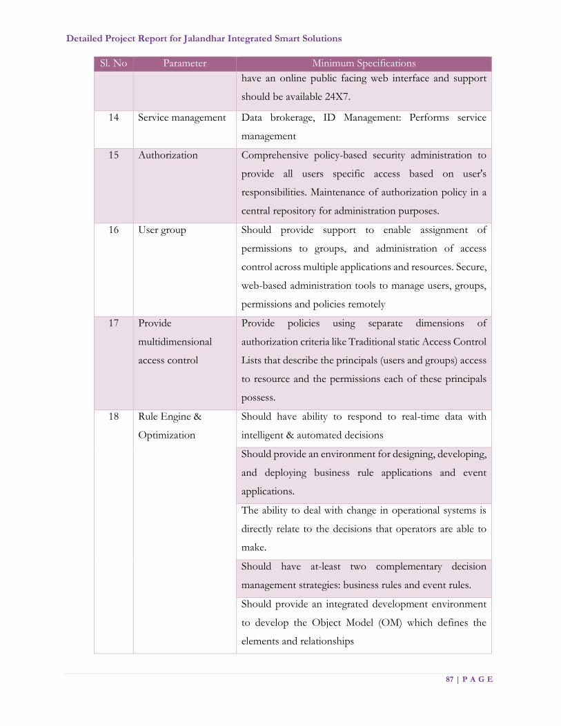
Detailed Project Report for Jalandhar Integrated Smart Solutions
87 | P A G E
Sl. No Parameter Minimum Specifications
have an online public facing web interface and support
should be available 24X7.
14 Service management Data brokerage, ID Management: Performs service
management
15 Authorization Comprehensive policy-based security administration to
provide all users specific access based on user's
responsibilities. Maintenance of authorization policy in a
central repository for administration purposes.
16 User group Should provide support to enable assignment of
permissions to groups, and administration of access
control across multiple applications and resources. Secure,
web-based administration tools to manage users, groups,
permissions and policies remotely
17 Provide
multidimensional
access control
Provide policies using separate dimensions of
authorization criteria like Traditional static Access Control
Lists that describe the principals (users and groups) access
to resource and the permissions each of these principals
possess.
18 Rule Engine &
Optimization
Should have ability to respond to real-time data with
intelligent & automated decisions
Should provide an environment for designing, developing,
and deploying business rule applications and event
applications.
The ability to deal with change in operational systems is
directly relate to the decisions that operators are able to
make.
Should have at-least two complementary decision
management strategies: business rules and event rules.
Should provide an integrated development environment
to develop the Object Model (OM) which defines the
elements and relationships

Detailed Project Report for Jalandhar Integrated Smart Solutions
88 | P A G E
Sl. No Parameter Minimum Specifications
19 Remote Video
Display
The system should support dynamic reduction of bit rate
and bandwidth for each stream based on the viewing
resolution at the remote location. (Example: If the remote
station is viewing with 352 x 240 (CIF), the stream to
remote viewing location should not be using HD
bandwidth, but dynamically should change to lower
bandwidth. If the remote viewing station is viewing this
camera in full screen 1080P, then it should dynamically
increase the bandwidth to provide HD experience.)
The system should use dynamic channel coverage
specifically for video stream function for efficient
bandwidth usage for multiple operation center and only
transmits video stream required to display on monitor to
maximize bandwidth efficiency and should support 20 to
30 camera feeds in single display.
The solution should comprise of video processing server.
This server must be able to carter to following functional
requirements:
a. To process and transmit video streams adaptive to each
video requests to optimize network bandwidth usage.
b. Shall be able to distribute real-time video streams
without any loss in original video quality
20 Device Engine Aggregation and abstraction of sensors: provides
aggregation of sensors from diverse sensor cloud
Normalization of sensor data organizes sensor data and
assigns attributes based on relations; raw data removed
and passed to data engine
21 Location Engine Map services and geospatial coordinates: provides the
geographical coordinates of specific facilities, roads, and
city infrastructure assets, as well as unmapped facilities

Detailed Project Report for Jalandhar Integrated Smart Solutions
89 | P A G E
Sl. No Parameter Minimum Specifications
Geospatial calculation calculates distance between two, or
more, locations on the map
Location-based tracking locates and traces devices on the
map
22 Enterprise Resource
Planning (ERP)
Integration
capabilities
System should allow integration of business process in
ERP workflows like property, water tax collection etc.
23 Data Engine Data archive and logging: stores data feeds from the
device engine and external data sources
24 Incident
Management
Requirements
Should provide facility to capture critical information such
as location, name, status, time of the incident and be
modifiable in real time by multiple authors with role
associated permissions (read, write).
Incidents should be captured in standard formats to
facilitate incident correlation and reporting.
The system must provide Incident Management Services
to facilitate the management of response and recovery
operations
Should support comprehensive reporting on event status
in real time manually or automatically by a sensor/CCTV
video feeds.
Should support for multiple incidents with both
segregated and/or overlapping management and response
teams.
Should support for sudden critical events and linkage to
standard operating procedures automatically without
human intervention.
Allow operator to share/transfer the incident report to
Mobile Device/another operator’s console
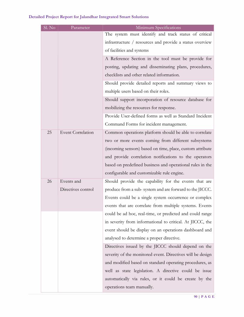
Detailed Project Report for Jalandhar Integrated Smart Solutions
90 | P A G E
Sl. No Parameter Minimum Specifications
The system must identify and track status of critical
infrastructure / resources and provide a status overview
of facilities and systems
A Reference Section in the tool must be provide for
posting, updating and disseminating plans, procedures,
checklists and other related information.
Should provide detailed reports and summary views to
multiple users based on their roles.
Should support incorporation of resource database for
mobilizing the resources for response.
Provide User-defined forms as well as Standard Incident
Command Forms for incident management.
25 Event Correlation Common operations platform should be able to correlate
two or more events coming from different subsystems
(incoming sensors) based on time, place, custom attribute
and provide correlation notifications to the operators
based on predefined business and operational rules in the
configurable and customizable rule engine.
26 Events and
Directives control
Should provide the capability for the events that are
produce from a sub- system and are forward to the JICCC.
Events could be a single system occurrence or complex
events that are correlate from multiple systems. Events
could be ad hoc, real-time, or predicted and could range
in severity from informational to critical. At JICCC, the
event should be display on an operations dashboard and
analysed to determine a proper directive.
Directives issued by the JICCC should depend on the
severity of the monitored event. Directives will be design
and modified based on standard operating procedures, as
well as state legislation. A directive could be issue
automatically via rules, or it could be create by the
operations team manually.

Detailed Project Report for Jalandhar Integrated Smart Solutions
91 | P A G E
Sl. No Parameter Minimum Specifications
27 Device Status,
Obstruction
Detection and
Availability
Notification
Should provide icon based user interface on the GIS map
to report non-functional device.
Should also provide a single tabular view to list all devices
along with their availability status in real time.
Shall view the environment through geospatial or fixed
composite computer- generated (JPEG, BMP,
AutoCAD, etc.) map
Should allow user to view sensor or system data and
related name from the displayed map
Should visually display a camera sensor with related
camera orientation, camera range and camera field of view
angle.
Should allow all resources, objects, sensors and elements
on the map to be georeferenced such that they have a real
world coordinate.
Should allow user to choose camera and take live video
image snapshot and save to file from any camera
Should allow user to choose camera from map to move
PTZ cameras
Should allow map information “layers” to be
displayed/hidden on items such as sensor names, Sensors,
sensor range (e.g. camera – orientation, range, field of view
angle), Locations and zones, Perimeter ranges
Should provide User Interface to publish messages to
multiple devices at the same time
28 Standard Operations
Procedures (SOPs)
Solution should provide for authoring and invoking un-
limited number of configurable and customizable
standard operating procedures through graphical, easy to
use tooling interface and support English and Hindi
language and optionally Punjabi.

Detailed Project Report for Jalandhar Integrated Smart Solutions
92 | P A G E
Sl. No Parameter Minimum Specifications
Standard Operating Procedures should be establish,
approved sets of actions considered the best practices for
responding to a situation or carrying out an operation.
The users should be able to edit the SOP, including
adding, editing, or deleting the activities.
It shall have facility to define more than one SOP for the
selected alert category or location
The users should be able to also add comments to or stop
the SOP (prior to completion).
Operations/Actions are automatically log in audit trail,
changes, and commentary for the SOP and its activities,
so that an electronic record is available for after-action
review.
The SOP Tool should have capability to define the
following activity types:
Manual Activity - An activity that is done manually by the
owner and provide details in the description field.
Automation Activity - An activity that initiates and tracks
a particular work order and select a predefined work order
from the list.
If-Then-Else Activity - A conditional activity that allows
branching based on specific criteria. Either enter or select
values for Then and Else.
Notification Activity - An activity that displays a
notification window that contains an email template for
the activity owner to complete, and then sends an email
and SMS notification.
SOP Activity - An activity that launches another standard
operating procedure.
29 KPI Display Solution should be able to facilitate measurement or
criteria to assay the condition or performance of
departmental processes & policies.
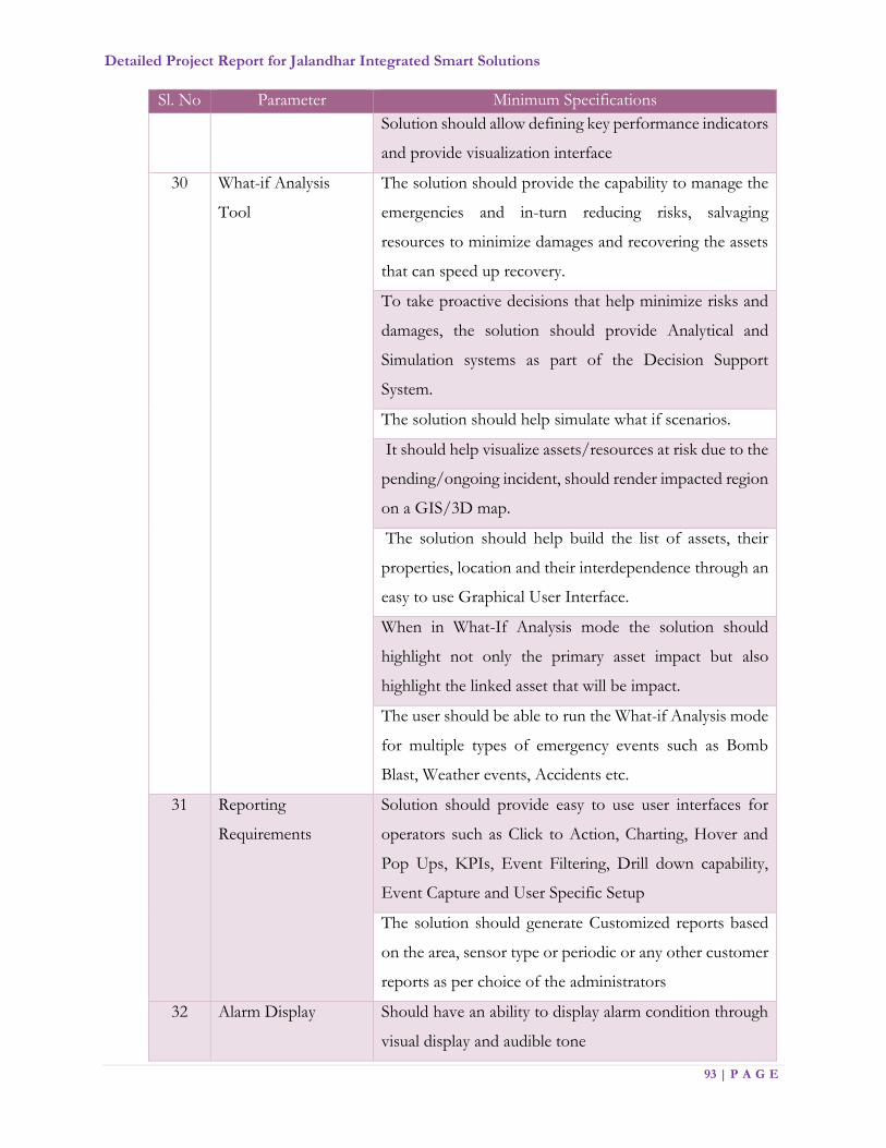
Detailed Project Report for Jalandhar Integrated Smart Solutions
93 | P A G E
Sl. No Parameter Minimum Specifications
Solution should allow defining key performance indicators
and provide visualization interface
30 What-if Analysis
Tool
The solution should provide the capability to manage the
emergencies and in-turn reducing risks, salvaging
resources to minimize damages and recovering the assets
that can speed up recovery.
To take proactive decisions that help minimize risks and
damages, the solution should provide Analytical and
Simulation systems as part of the Decision Support
System.
The solution should help simulate what if scenarios.
It should help visualize assets/resources at risk due to the
pending/ongoing incident, should render impacted region
on a GIS/3D map.
The solution should help build the list of assets, their
properties, location and their interdependence through an
easy to use Graphical User Interface.
When in What-If Analysis mode the solution should
highlight not only the primary asset impact but also
highlight the linked asset that will be impact.
The user should be able to run the What-if Analysis mode
for multiple types of emergency events such as Bomb
Blast, Weather events, Accidents etc.
31 Reporting
Requirements
Solution should provide easy to use user interfaces for
operators such as Click to Action, Charting, Hover and
Pop Ups, KPIs, Event Filtering, Drill down capability,
Event Capture and User Specific Setup
The solution should generate Customized reports based
on the area, sensor type or periodic or any other customer
reports as per choice of the administrators
32 Alarm Display Should have an ability to display alarm condition through
visual display and audible tone

Detailed Project Report for Jalandhar Integrated Smart Solutions
94 | P A G E
Sl. No Parameter Minimum Specifications
Should have an ability to simultaneously handle
multiple alarms from multiple workstations
Should have an ability to automatically prioritize and
display multiple alarms and status conditions according to
pre-defined parameters such as alarm type, location,
sensor, severity, etc.
Should display the highest priority alarm and associated
data / video in the queue as default, regardless of the
arrival sequence.
33 Historical Alarm
Handling
Should have an ability to view historical alarms details
even after the alarm has been acknowledge or closed.
Should have an ability to sort alarms according to
date/time, severity, type, and sensor ID or location.
34 Alarm Reporting Should have an ability to generate a full incident report of
the alarm being generate.
Should have an ability to display report on monitor and
print report.
Should have details of alarm including severity, time/date,
description and location.
Captured video image snapshots.
Relevant sensor data such as SCADA sensors, Response
instructions, Alarm activities, (audit trail).
Should have an ability to export alarm report in various
formats including pdf, jpeg, html, txt, and mht formats.
Should have an ability to generate an alarm incident
package including the full incident report and exported
sensor data from the incident in a specific folder location.
35 The solution should have the following ability to handle
the workflow alarms through graphical user interface.

Detailed Project Report for Jalandhar Integrated Smart Solutions
95 | P A G E
Sl. No Parameter Minimum Specifications
Alarm Policies and
Business Logic
Administration
Should have an ability to match keywords or text from the
alarming subsystem’s incident description to raise an
alarm using criteria including exact match, exact not
match, contains match, wildcard match and regularly
expression match (such as forced door alarm, denied
access, door open too long, etc.)
Should have an ability to optionally match alarming
subsystem’s incident status, incident severity, and sensor
type
Should have an ability to apply any alarm policy to one or
more monitoring area(s) or zone(s) without having to
reapplying the policy multiple times.
Should have an ability to apply any alarm policy to one or
more sensors without having to reapply the policy
multiple times.
Should have an ability to assign specific actions for each
alarm
Should have an ability to activate or deactivate alarms as
required
Should have an ability to create exceptions
Should Create batch-wise rules and process them
Should Check and rectify logical errors and contradictory
rules
Should have an ability to schedule execution of rules
Should Suspend or Terminate the application of rule
Should archive unused or deactivated rules
36 Collaboration
Framework/ Tools
Shall establish a collaborative framework where input
from different functional departments of city municipal
corporation and other smart city stakeholders such as
transport, water, police, e-governance, etc. can be
assimilated and analyse on a single platform; consequently
resulting in aggregated city level information.

Detailed Project Report for Jalandhar Integrated Smart Solutions
96 | P A G E
Sl. No Parameter Minimum Specifications
This aggregated city level information can be convert to
actionable intelligence, which would be propagate to
relevant stakeholders and citizens.
Cross collaboration APIs: Enabling contextual
information and correlation across domains and verticals
(Multiple vendor and Multi-sensor in future) and support
security standards: OAuth 2.0, HTTPS over SSL, and key
management
The common operations platform` should have the
capability to bring in multiple stake holders automatically
into a common collaboration platform like persistent chat
rooms and virtual meeting rooms in response to a SOP
defined to handle a particular event.
The stakeholders can be on various types of devices like
computer, smart phones, tablets or normal phones.
The operator should also have ability to create these
collaboration spaces like virtual meeting rooms or chat
groups manually.
Shall offer the ability to create graphical displays that are
representing real-time conditions in a useful, intuitive
format.
Shall enable the user to look at various operating areas and
see, at a glance,
What’s going on?
What are the current problems?
What things are going well?
Do I need to dispatch maintenance/ emergency
response?
Should provide tools for users to collaborate &
communicate in real-time using instant messaging
features.

Detailed Project Report for Jalandhar Integrated Smart Solutions
97 | P A G E
Sl. No Parameter Minimum Specifications
37 Communication
Requirements
The solution should adhere to the below mentioned
communication requirements.
Provide the ability to search/locate resources based on
name, department, role, geography, skill etc. for rapidly
assembling a team, across department, divisions and
agency boundaries during emergency
Provide the capability to invite using information
provided during the location of those individuals or roles,
invite them to collaborate and to share valuable
information.
Provide a single web based dashboard to send
notifications to target audiences using multiple
communication methods including voice‐based
notification on PSTN/Cellular, SMS, Voice mail, E‐ mail
and Social Media
The solution should provide Dispatch Console integration
with various communication channels.
It should provide rich media support for incidents, giving
dispatchers the power to consolidate information relating
to an incident and instantly share that information among
responder teams.
It should assess the common operating picture, identify &
dispatch mobile resources available nearby the incident
location. Augment resources from multiple agencies for
coordinated response.
38 Instant Messaging Provide ability to converse virtually through the exchange
of text, audio, and/or video-based information in real time
with one or more individuals within the emergency
management community.

Detailed Project Report for Jalandhar Integrated Smart Solutions
98 | P A G E
Sl. No Parameter Minimum Specifications
39 Alert & Mass
Notification
Requirements
The system should provide the software component for
the message broadcast and notification solution that
allows authorized personal and/or business processes to
send large number of messages to target audience (select-
call or global or activation of pre-programmed list) using
multiple communication methods including SMS, Voice
(PSTN/Cellular), Email and Social Media.
Provide a single web based dashboard to send
notifications to target audiences using multiple
communication methods including voice-based
notification on PSTN/Cellular, SMS, Pager, Voice mail,
E-mail and Social media
Provide function for creating the alert content and
disseminating to end users.
Provision of alerting external broadcasting organizations
like Radio, TV, Cellular, etc., as web-service.
40 Analytics Engine Analytics Engine should be an artificial intelligence-based
smart city analytics platform module to maximize business
value through advanced machine learning capabilities. The
machine learning capabilities aid in automating policies
that result in better asset and infrastructure management.
The solution should be flexible to integrate with other city
and government software applications.
Analytics Engine module should have below intelligence
capabilities:
a) Advanced Predictive Analytics should be part of the
solution.
b) The solution should be flexible to integrate with other
city and government software applications
c) The solution should be able to predict insights
consuming data from city infrastructure viz., CCTV
Surveillance, Traffic etc.
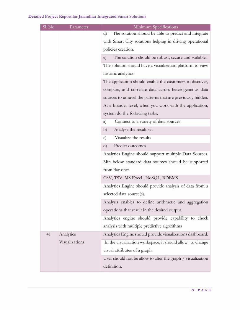
Detailed Project Report for Jalandhar Integrated Smart Solutions
99 | P A G E
Sl. No Parameter Minimum Specifications
d) The solution should be able to predict and integrate
with Smart City solutions helping in driving operational
policies creation.
e) The solution should be robust, secure and scalable.
The solution should have a visualization platform to view
historic analytics
The application should enable the customers to discover,
compare, and correlate data across heterogeneous data
sources to unravel the patterns that are previously hidden.
At a broader level, when you work with the application,
system do the following tasks:
a) Connect to a variety of data sources
b) Analyse the result set
c) Visualize the results
d) Predict outcomes
Analytics Engine should support multiple Data Sources.
Min below standard data sources should be supported
from day one:
CSV, TSV, MS Excel , NoSQL, RDBMS
Analytics Engine should provide analysis of data from a
selected data source(s).
Analysis enables to define arithmetic and aggregation
operations that result in the desired output.
Analytics engine should provide capability to check
analysis with multiple predictive algorithms
41 Analytics
Visualizations
Analytics Engine should provide visualizations dashboard.
In the visualization workspace, it should allow to change
visual attributes of a graph.
User should not be allow to alter the graph / visualization
definition.

Detailed Project Report for Jalandhar Integrated Smart Solutions
100 | P A G E
Sl. No Parameter Minimum Specifications
In the visualizations workspace, user should able to do the
following operations:
a) Change the graph/visualization type
b) Print the graph
c) Export the graph
d) Narrow down on the value ranges
e) Toggle the axis labels
Integrate with other 3rd party applications seamlessly
42 Integration with
Social Media & Open
Source Intelligence
Should provide integration of the Incident Management
application with the social media.
Should provide analytics based on the social media feed
collected from the open source intelligence and collate
with the surveillance inputs to alert the responders for
immediate action on the ground.
Should provide notifications to multiple agencies and
departments (on mobile) that a new intelligence has been
gather through open source/social media.
Should be able to identify the critical information and
should be able to link it to an existing SOP or a new SOP
should be started.
Should extract messages and display it in an operational
dashboard.
Should be able to correlate the extracted message from the
social media with existing other events and then should be
able to initiate an SOP.
43 Field operator
module
Shall provide a mobile application for field operators
bundled together with JICCC platform with at least 50
licenses
Application shall provide incident management, SOPs and
operations platform
Operator shall be able to view the JICCC components
based on set user permissions

Detailed Project Report for Jalandhar Integrated Smart Solutions
101 | P A G E
Sl. No Parameter Minimum Specifications
44 Summary Dashboard Shall provide alarm summary of each monitoring zone or
monitoring area in graphical chart format
Shall display the following charts per global area,
monitoring zone or monitoring area
Shall Open Alert Count by Monitoring Zone/Monitoring
Area
Shall have the capability of New vs. Viewed (Opened
Alerts)
Shall Open Alert Count by Alert Severity
Should have Highest Severity Alert
Shall enable Monitoring Zone or Monitoring area default
to Summary view dashboard or to a map when the zone
or area is select.
Shall provide a tabular list of sensors in each monitoring.
Integration Capabilities
List of Services Minimum Specifications
Integration of Intelligent Traffic
Management System (Police)
JICCC will be required to integrate with
Command Center of Traffic Management
System, to receive real-time feeds of the camera
installed by them.
These video feeds will not be save, but will be
utilize in Analytical layer to help administration
monitor its assets and do a better urban
planning.
Integration with CCTV
Surveillance (Police Dep't.)
JICCC will be required to integrate with CCTV
Surveillance System to receive real-time feeds of
the camera installed by them. These video feeds

Detailed Project Report for Jalandhar Integrated Smart Solutions
102 | P A G E
List of Services Minimum Specifications
will be saved and utilized in Analytical layer to
create safe city
Integration of Call Centre
Services
JICCC will be required to integrate its helpdesk
and system with call center, in case if there is
some information or notification is to be send
to call center for doing some action in the field
regarding Municipal Corporation work.
All the information received from the
command center will also go into the Analytical
layer, which will help city in better planning and
running of operations.
JICCC will be required to integrate with the
backend system of Jalandhar Municipal
Corporation (MCJ).
JICCC should be able to integrate with the
existing ICT systems and edge / end / mobile
devices of various MC departments such as
Garden, General Administration Department,
Water Supply, Sewerage, Assessment and
Collection (Property Tax, Shops and
establishment), Fire (Fire Brigade Section),
Transport of Heavy Vehicles and Maintenance
(Workshop), Audit and License Issue to receive
and send information.
JICCC should be able to map the data received
from various MC departments on its GIS
Platform.
JICCC will be required to send field agents,
alerts and notifications for any emergency /
incidents / disaster in the city for doing required
action.
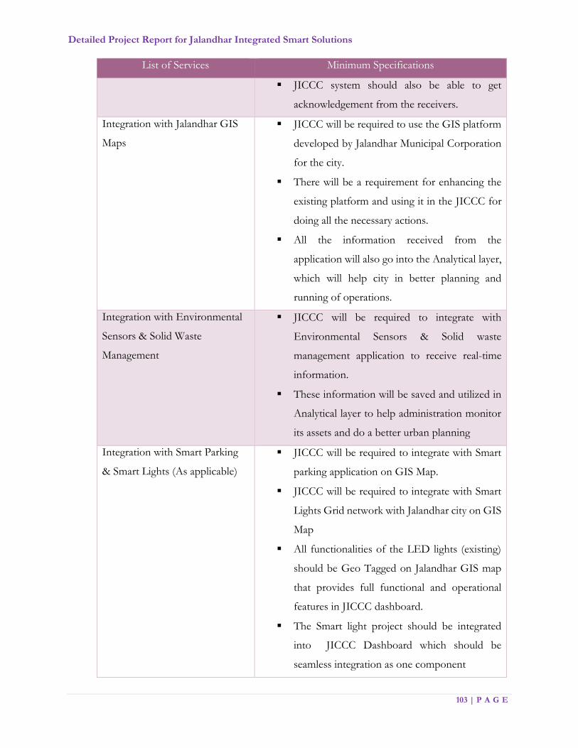
Detailed Project Report for Jalandhar Integrated Smart Solutions
103 | P A G E
List of Services Minimum Specifications
JICCC system should also be able to get
acknowledgement from the receivers.
Integration with Jalandhar GIS
Maps
JICCC will be required to use the GIS platform
developed by Jalandhar Municipal Corporation
for the city.
There will be a requirement for enhancing the
existing platform and using it in the JICCC for
doing all the necessary actions.
All the information received from the
application will also go into the Analytical layer,
which will help city in better planning and
running of operations.
Integration with Environmental
Sensors & Solid Waste
Management
JICCC will be required to integrate with
Environmental Sensors & Solid waste
management application to receive real-time
information.
These information will be saved and utilized in
Analytical layer to help administration monitor
its assets and do a better urban planning
Integration with Smart Parking
& Smart Lights (As applicable)
JICCC will be required to integrate with Smart
parking application on GIS Map.
JICCC will be required to integrate with Smart
Lights Grid network with Jalandhar city on GIS
Map
All functionalities of the LED lights (existing)
should be Geo Tagged on Jalandhar GIS map
that provides full functional and operational
features in JICCC dashboard.
The Smart light project should be integrated
into JICCC Dashboard which should be
seamless integration as one component
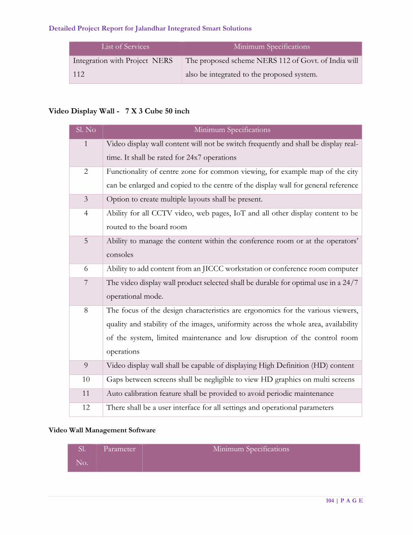
Detailed Project Report for Jalandhar Integrated Smart Solutions
104 | P A G E
List of Services Minimum Specifications
Integration with Project NERS
112
The proposed scheme NERS 112 of Govt. of India will
also be integrated to the proposed system.
Video Display Wall - 7 X 3 Cube 50 inch
Sl. No Minimum Specifications
1 Video display wall content will not be switch frequently and shall be display real-
time. It shall be rated for 24x7 operations
2 Functionality of centre zone for common viewing, for example map of the city
can be enlarged and copied to the centre of the display wall for general reference
3 Option to create multiple layouts shall be present.
4 Ability for all CCTV video, web pages, IoT and all other display content to be
routed to the board room
5 Ability to manage the content within the conference room or at the operators’
consoles
6 Ability to add content from an JICCC workstation or conference room computer
7 The video display wall product selected shall be durable for optimal use in a 24/7
operational mode.
8 The focus of the design characteristics are ergonomics for the various viewers,
quality and stability of the images, uniformity across the whole area, availability
of the system, limited maintenance and low disruption of the control room
operations
9 Video display wall shall be capable of displaying High Definition (HD) content
10 Gaps between screens shall be negligible to view HD graphics on multi screens
11 Auto calibration feature shall be provided to avoid periodic maintenance
12 There shall be a user interface for all settings and operational parameters
Video Wall Management Software
Sl.
No.
Parameter Minimum Specifications

Detailed Project Report for Jalandhar Integrated Smart Solutions
105 | P A G E
1 Display &
Scaling
Display multiple sources anywhere on display up to any size
2 Input
Management
All input sources can be displayed on the video wall in freely resizable and
movable windows
3 Scenarios
management
Save and load desktop layouts from local or remote machines
4 Layout
Management
Support all layout from input sources, Internet Explorer, desktop and
remote desktop application
5 Multi View
Option
Multiple view of portions or regions of Desktop, multiple application can
view from single desktop
6
Other
features
SMTP support
Remote Control over LAN
Alarm management
Remote management
Multiple concurrent client
KVM support
7
Cube
Management
Cube Health Monitoring
Pop‐Up Alert Service
Graphical User Interface
8 Remote
Viewing
The video wall content will be able to show live on any remote display
.Mobile with IE
9 Integration The video wall software should have tight integration with VMS and
JICCC application
Data Centre
The Jalandhar Smart City intends to establish a Data Center (DC) in the premises of the JICCC.
It will be the obligation of the MSI to implement and commission the DC at the selected location
as approved by the JSCL.
The MSI is required to implement all the hardware/software and related items for the data center
as per the smart city solution including SLA monitoring & Help desk management, in a Tier III
Data Center complying with standard guidelines as per Telecommunications Infrastructure
UPTIME/TIA-942.

Detailed Project Report for Jalandhar Integrated Smart Solutions
106 | P A G E
The Data center shall be available for 24x7x365 operation. The smart city infrastructure shall have
built in redundancy and high availability in compute and storage to ensure that there is no single
point of failure. The MSI shall submit to JSCL adequate documentation/ evidences in support of
the choice of the data center to meet the project requirements.
Any commercially available database (e.g., SQL or equivalent), shall be provided along with license
and support and upgrade costs.
Server Infrastructure Zone
This zone shall host servers, server racks, storage racks and networking components like routers,
switches to passive components. All the Data center LAN connections shall be provided through
switches placed in this area. MSI shall be required to undertake a detailed assessment of the space
and size of the building proposed by JSCL for JICCC with co-hosted data center with respect to
their system requirements and if required may propose a suitable solution. Access to this zone,
where the surveillance project IT infrastructure is hosed, shall be demarcated and physical access
to the place shall be given only to the authorized personnel. Indoor CCTV Cameras shall be
installed to monitor the physical access of the system from remote location.
UPS and Electrical Zone
This zone shall house all the Un-Interrupted Power Supply units, Main Power Distribution Units
(PDUs) to feed the components such as PAC, UPS, lighting, fixtures etc. This shall also house all
the batteries accompanying the UPS components. As these generate good amount of radiation, it
is advised to house these components in a room separate from server infrastructure zone.
Following are the benchmark requirements, which should act as guiding factors for the MSI:
Access to the Data Center Space where the Smart City project infrastructure is proposed
to be hosted should be demarcated and physical access to the place would be given only
to the authorized personnel.
Racks to be caged.
Smart City Data Center should be at least a Tier III Data Center as per
Telecommunications Infrastructure Standard for Data Center and should be 27001
Certified.
It should have Access Control System implemented for secured access.
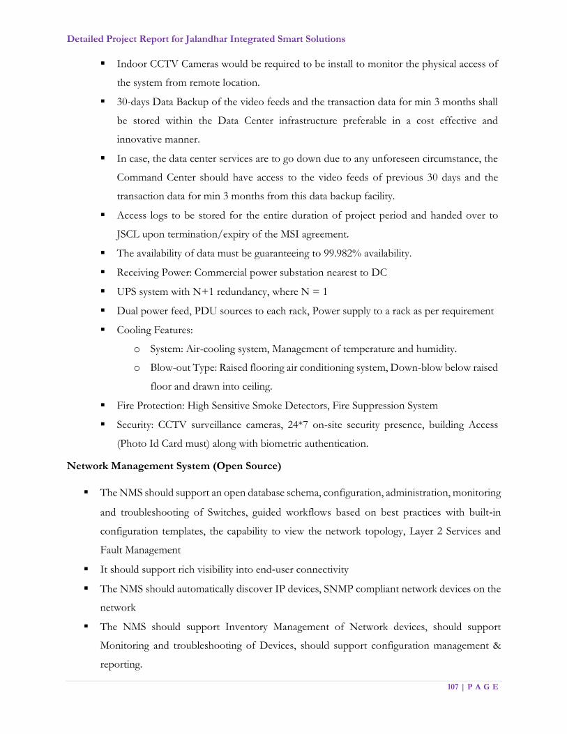
Detailed Project Report for Jalandhar Integrated Smart Solutions
107 | P A G E
Indoor CCTV Cameras would be required to be install to monitor the physical access of
the system from remote location.
30-days Data Backup of the video feeds and the transaction data for min 3 months shall
be stored within the Data Center infrastructure preferable in a cost effective and
innovative manner.
In case, the data center services are to go down due to any unforeseen circumstance, the
Command Center should have access to the video feeds of previous 30 days and the
transaction data for min 3 months from this data backup facility.
Access logs to be stored for the entire duration of project period and handed over to
JSCL upon termination/expiry of the MSI agreement.
The availability of data must be guaranteeing to 99.982% availability.
Receiving Power: Commercial power substation nearest to DC
UPS system with N+1 redundancy, where N = 1
Dual power feed, PDU sources to each rack, Power supply to a rack as per requirement
Cooling Features:
o System: Air-cooling system, Management of temperature and humidity.
o Blow-out Type: Raised flooring air conditioning system, Down-blow below raised
floor and drawn into ceiling.
Fire Protection: High Sensitive Smoke Detectors, Fire Suppression System
Security: CCTV surveillance cameras, 24*7 on-site security presence, building Access
(Photo Id Card must) along with biometric authentication.
Network Management System (Open Source)
The NMS should support an open database schema, configuration, administration, monitoring
and troubleshooting of Switches, guided workflows based on best practices with built‐in
configuration templates, the capability to view the network topology, Layer 2 Services and
Fault Management
It should support rich visibility into end‐user connectivity
The NMS should automatically discover IP devices, SNMP compliant network devices on the
network
The NMS should support Inventory Management of Network devices, should support
Monitoring and troubleshooting of Devices, should support configuration management &
reporting.
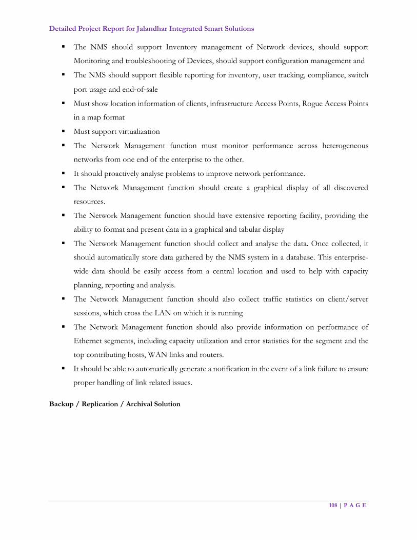
Detailed Project Report for Jalandhar Integrated Smart Solutions
108 | P A G E
The NMS should support Inventory management of Network devices, should support
Monitoring and troubleshooting of Devices, should support configuration management and
The NMS should support flexible reporting for inventory, user tracking, compliance, switch
port usage and end‐of‐sale
Must show location information of clients, infrastructure Access Points, Rogue Access Points
in a map format
Must support virtualization
The Network Management function must monitor performance across heterogeneous
networks from one end of the enterprise to the other.
It should proactively analyse problems to improve network performance.
The Network Management function should create a graphical display of all discovered
resources.
The Network Management function should have extensive reporting facility, providing the
ability to format and present data in a graphical and tabular display
The Network Management function should collect and analyse the data. Once collected, it
should automatically store data gathered by the NMS system in a database. This enterprise-
wide data should be easily access from a central location and used to help with capacity
planning, reporting and analysis.
The Network Management function should also collect traffic statistics on client/server
sessions, which cross the LAN on which it is running
The Network Management function should also provide information on performance of
Ethernet segments, including capacity utilization and error statistics for the segment and the
top contributing hosts, WAN links and routers.
It should be able to automatically generate a notification in the event of a link failure to ensure
proper handling of link related issues.
Backup / Replication / Archival Solution
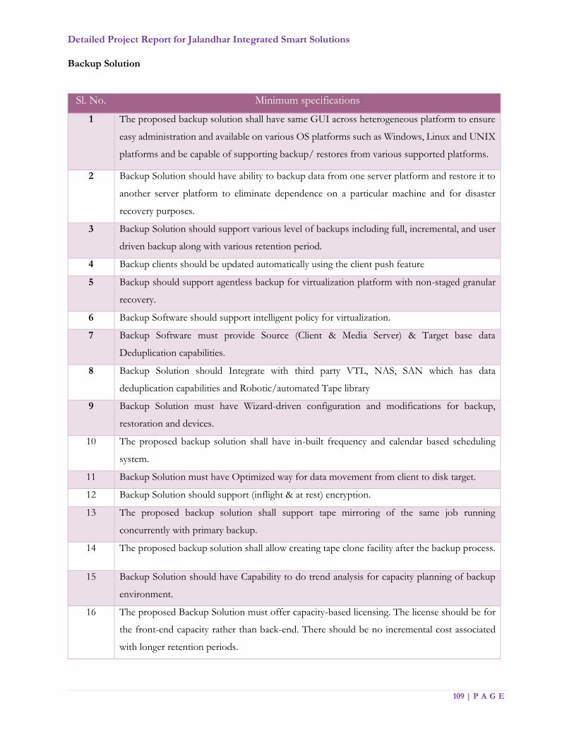
Detailed Project Report for Jalandhar Integrated Smart Solutions
109 | P A G E
Backup Solution
Sl. No. Minimum specifications
1 The proposed backup solution shall have same GUI across heterogeneous platform to ensure
easy administration and available on various OS platforms such as Windows, Linux and UNIX
platforms and be capable of supporting backup/ restores from various supported platforms.
2 Backup Solution should have ability to backup data from one server platform and restore it to
another server platform to eliminate dependence on a particular machine and for disaster
recovery purposes.
3 Backup Solution should support various level of backups including full, incremental, and user
driven backup along with various retention period.
4 Backup clients should be updated automatically using the client push feature
5 Backup should support agentless backup for virtualization platform with non-staged granular
recovery.
6 Backup Software should support intelligent policy for virtualization.
7 Backup Software must provide Source (Client & Media Server) & Target base data
Deduplication capabilities.
8 Backup Solution should Integrate with third party VTL, NAS, SAN which has data
deduplication capabilities and Robotic/automated Tape library
9 Backup Solution must have Wizard-driven configuration and modifications for backup,
restoration and devices.
10 The proposed backup solution shall have in-built frequency and calendar based scheduling
system.
11 Backup Solution must have Optimized way for data movement from client to disk target.
12 Backup Solution should support (inflight & at rest) encryption.
13 The proposed backup solution shall support tape mirroring of the same job running
concurrently with primary backup.
14 The proposed backup solution shall allow creating tape clone facility after the backup process.
15 Backup Solution should have Capability to do trend analysis for capacity planning of backup
environment.
16 The proposed Backup Solution must offer capacity-based licensing. The license should be for
the front-end capacity rather than back-end. There should be no incremental cost associated
with longer retention periods.

Detailed Project Report for Jalandhar Integrated Smart Solutions
110 | P A G E
17 The solution should not require purchase of additional licenses for DR sites (copies of original
data), also should not require purchase of additional licenses for replication to DR sites.
18 The proposed backup solution license should be independent of hardware so replacing
hardware should not incur new software license cost.
19 The proposed backup solution must include Agent/Modules for online backup of files,
applications and databases.
20 The proposed backup solution should provide recovery from physical servers to Virtual and
image level recovery.
21 The proposed backup solution should have Cloud plug-ins for backup data replication.
22 Backup Solution should have Inbuilt feature for extensive alerting and reporting with pre-
configured and customizable formats.
23 Backup Replication at DR site, Cloud. Replication license should be included as part of
solutions.
24 Backup software should support multiplexing and multi-streaming and shall support the
capability to write up to Min 32 data streams.
25 Backup Solutions should have capabilities to tape/disk out backup catalog and deduplication
catalog.
26 Backup solution should have integrated data de-duplication engine with multi-vendor storage
support to save de-duplication data. The de-duplication engine should also facilitate IP based
replication of de-dupe data; without any extra charge.
27 The Proposed Backup solution must be capable of restoring files, emails and other granular
items from different applications for e.g. File Exchange Server, Active Directory etc. and for
hypervisors, virtualisation software etc. from a single-pass backup.
28 Backup solution must Support Backups/Restores for:
Clustered servers (Industry popular clusters).
Virtual platform.
RAW SCSI volumes.
Block based backup & restore simultaneously.
Replication Solution
Sl. No. Minimum specifications
1 The proposed architecture should ensure that in event of Disaster at Primary Site, applications
can be restarted at DR Site without any data loss.

Detailed Project Report for Jalandhar Integrated Smart Solutions
111 | P A G E
2 The proposed architecture should focus on not only the data replication, but ensuring
application availability
3 The proposed solution must optimize additional infrastructure and storage resources in the
architecture.
4 The proposed solution should be a storage agnostic solution. The solution should not only
seamlessly integrate with current infrastructure, but also not impose any restriction on storage
or platform technology that JSCL may deploy in future.
5 The proposed software must provide comprehensive hardware and platform support. Support
for physical and virtual platforms.
6 The proposed software should provide application level availability by ensuring that it not only
replicates data within database but also structural changes to databases, application and database
binaries etc. without any manual intervention.
7 Application high availability at primary & DR site should not be dependent on Operating system
event logs. Solution should be capable to integrate directly with application start, stop and
monitor service to avoid outage remedy solution because of Operating system log.
8 The proposed software should support real time tracking of configuration changes being done
to Operating system, application binaries, any tuneable added/modified etc. and alert
administrators in case of configuration drift between primary and DR site.
9 Shall be able to handle long outages of network without affecting the consistency of data at
secondary site. The replication solution should be provisioned for storing data for at least 4 days
in case network is down for extended period.
10 The proposed software should provide for an automated fire-drill for testing of DR site. The
testing mechanism should automatically validate the application start up at DR site at a pre-
defined schedule defined.
11 The proposed software should provide availability across any distance—Builds local
metropolitan and wide-area clusters for disaster recovery and local availability.
12 The proposed software should ensure no single point of failure. It has the ability to gracefully
move an application to an available server in the event of a failure and coordinate the movement
with storage ownership.
13 The proposed software should provide Multi-cluster management and reporting, including
applications composed of multiple components running on different physical and virtual tiers,
adding resilience to business services. Manages and reports on multiple local and remote clusters
from a single unified web-based console.
14 The proposed software should provide seamless integration with all applications/databases
used for increased application performance and availability.
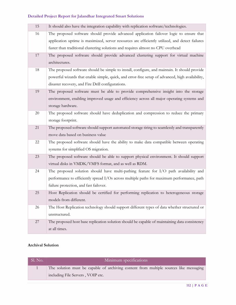
Detailed Project Report for Jalandhar Integrated Smart Solutions
112 | P A G E
15 It should also have the integration capability with replication software/technologies.
16 The proposed software should provide advanced application failover logic to ensure that
application uptime is maximized, server resources are efficiently utilized, and detect failures
faster than traditional clustering solutions and requires almost no CPU overhead
17 The proposed software should provide advanced clustering support for virtual machine
architectures.
18 The proposed software should be simple to install, configure, and maintain. It should provide
powerful wizards that enable simple, quick, and error-free setup of advanced, high availability,
disaster recovery, and Fire Drill configurations.
19 The proposed software must be able to provide comprehensive insight into the storage
environment, enabling improved usage and efficiency across all major operating systems and
storage hardware.
20 The proposed software should have deduplication and compression to reduce the primary
storage footprint.
21 The proposed software should support automated storage tiring to seamlessly and transparently
move data based on business value
22 The proposed software should have the ability to make data compatible between operating
systems for simplified OS migration.
23 The proposed software should be able to support physical environment. It should support
virtual disks in VMDK/VMFS format, and as well as RDM.
24 The proposed solution should have multi-pathing feature for I/O path availability and
performance to efficiently spread I/Os across multiple paths for maximum performance, path
failure protection, and fast failover.
25 Host Replication should be certified for performing replication to heterogeneous storage
models from different.
26 The Host Replication technology should support different types of data whether structured or
unstructured.
27 The proposed host base replication solution should be capable of maintaining data consistency
at all times.
Archival Solution
Sl. No. Minimum specifications
1 The solution must be capable of archiving content from multiple sources like messaging
including File Servers , VOIP etc.
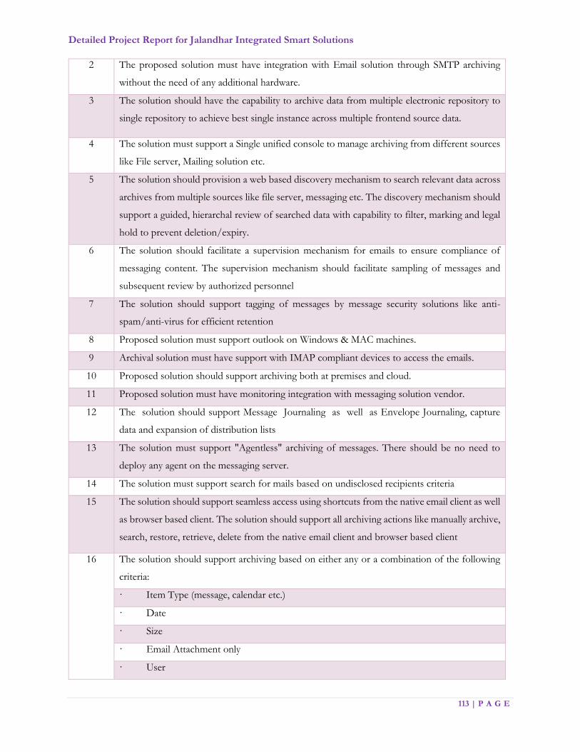
Detailed Project Report for Jalandhar Integrated Smart Solutions
113 | P A G E
2 The proposed solution must have integration with Email solution through SMTP archiving
without the need of any additional hardware.
3 The solution should have the capability to archive data from multiple electronic repository to
single repository to achieve best single instance across multiple frontend source data.
4 The solution must support a Single unified console to manage archiving from different sources
like File server, Mailing solution etc.
5 The solution should provision a web based discovery mechanism to search relevant data across
archives from multiple sources like file server, messaging etc. The discovery mechanism should
support a guided, hierarchal review of searched data with capability to filter, marking and legal
hold to prevent deletion/expiry.
6 The solution should facilitate a supervision mechanism for emails to ensure compliance of
messaging content. The supervision mechanism should facilitate sampling of messages and
subsequent review by authorized personnel
7 The solution should support tagging of messages by message security solutions like anti-
spam/anti-virus for efficient retention
8 Proposed solution must support outlook on Windows & MAC machines.
9 Archival solution must have support with IMAP compliant devices to access the emails.
10 Proposed solution should support archiving both at premises and cloud.
11 Proposed solution must have monitoring integration with messaging solution vendor.
12 The solution should support Message Journaling as well as Envelope Journaling, capture
data and expansion of distribution lists
13 The solution must support "Agentless" archiving of messages. There should be no need to
deploy any agent on the messaging server.
14 The solution must support search for mails based on undisclosed recipients criteria
15 The solution should support seamless access using shortcuts from the native email client as well
as browser based client. The solution should support all archiving actions like manually archive,
search, restore, retrieve, delete from the native email client and browser based client
16 The solution should support archiving based on either any or a combination of the following
criteria:
· Item Type (message, calendar etc.)
· Date
· Size
· Email Attachment only
· User

Detailed Project Report for Jalandhar Integrated Smart Solutions
114 | P A G E
· Organizational Unit
17 Proposed solution must have advance way of archive disk/partition data backup to avoid
backup of old partitions which must be possible with or without WORM devices.
18 The solution must allow the administrators to configure the following in shortcuts:
Include recipient information in the shortcuts.
Include nothing / original message body / custom message body in shortcuts.
Include "X" number of characters in the shortcut.
Include a custom body defined from a configuration file in the shortcut etc.
19 The solution should leave a shortcut at either the time of archiving or later as well.
20 The solution should allow users to view archived items directly without having the need to
restore them to the messaging server to avoid delays and impact on messaging solution. No
network connections should be established between archiving server and messaging server at
the time of retrieving archived items
21 The solution must support indexing and archiving of minimum 500+ commonly used file types.
22 The solution should support archiving of entire email folders and application of selective
archiving policies based upon folders.
23 The solution must support dynamic retention period of archived items i.e. retention of archived
items can be increased or decreased on fly.
24 The solution should facilitate "future proofing" of content by facilitating an HTML copy for
long term retention and search
25 The solution should support "safety copies" of items to be kept on the mail server. The "safety
copy" allows the archiving software to wait for the archived item to be backed up or replicated
before the original item is removed from the mail server.
26 Archival solution must have option to set or configure disk property read and read-write access
27 Archival solution must have disk configurable option with High & Low watermark. In case,
High watermark reaches, disk should automatically become Read only and other pre-configured
disk should get read-write access to store fresh archived items.
28 The solution must have OWA integration in such a fashion that archived item can be browsed
directly through archived browser tab instead of browsing through internet explorer (IE). IE
can be additional feature.
29 The archival solution must have an integrated e-discovery solution which allows guided
Discovery, review and analysis of data from the archives and non-archived data like desktop,
file server, Documentum etc. It’s required for future proofing.

Detailed Project Report for Jalandhar Integrated Smart Solutions
115 | P A G E
30 Proposed Archival solution must have seamless and consistent end user search experience
across multiple interface like Desktop/Laptop, mobile, tablets etc.
Application Delivery Controller with Web Application Firewall (WAF)
Sl. No Minimum Specifications
1 MSI has to design next generation data center in order to meet the modern networking
requirements including software define networking, network function virtualization, agility,
portability & programmability. MSI has to ensure multiple network functions to consolidated
on purpose built hardware NFV to ensure
2 Multi-tenancy with Traffic isolation
3 Guaranteed performance – dedicated hardware resources including vCPU’s, I/O, memory, SSL
card, per virtual function , SR-IOV , open vSwitch
4 REST-API/Cloud API support for integration with centralized orchestration, cloud platform,
and elasticity
5 Support for multiple network functions on single platform depending on throughput and
capacity requirements per virtual functions
6 Support for multiple network functions including application firewall and reverse proxy with
application load balancing on same platform
7 The appliance should have minimum 8 x10G SFP+ data interfaces from day one
8 The appliance should support Minimum 64GB RAM, 2*SSL ASICS/FGPA/cards with SSL
I/O virtual function support for guaranteed SSL performance and 2TB HDD
Minimum Performance Specification
1 Should be high performance purpose built next generation multi-tenant hardware with
multicore CPU support. Platform should support multiple network functions including
application load balancing, application firewall network functions with dedicated hardware
resources for each virtual functions
2 Platform should support at least three network functions in order to cater current and future
requirements and performance numbers including throughput, connections, SSL throughput
and SSL transactions must be per virtual instance
For Reverse Proxy & Load Balancer – Network Functions
1 15 Gbps of system throughput, 5 Gbps of SSL throughput
2 Minimum of 1.2 M concurrent connection

Detailed Project Report for Jalandhar Integrated Smart Solutions
116 | P A G E
3 Minimum of 8K SSL transaction Per Second per instance (2048 key)
4 Dedicated Management Interface
5 For Web Application Firewall – network function
6 There should be dedicated instance for Web Application Firewall with at least 2Gbps of layer7
throughput
7 Platform should have capacity to accommodate at least one additional instance of same capacity
for all network functions mentioned above or 2 x numbers of instances with 50% capacity
mentioned above
Functional Specification
1 Meet all applicable PCI DSS requirements pertaining to system components and react
appropriately (defined by active policy or rules) to threats against relevant vulnerabilities. WAF
can be proposed as Network function on next generation platform or dedicated purpose built
hardware. Platform should be scalable to accommodate more WAF function to meet the
performance requirements
2 The Web application firewall should support positive security model with machine learning
capabilities to detect and prevent vulnerabilities and anomalies in application traffic and
unknown attacks. Machine learning should be based on true ML algorithms, and not just
automation of dynamically learnt rules
3 New modules of applications should be learnt dynamically, and WAF should also provide the
option of deploying the rules learnt dynamically for these new modules without manual
intervention
4 WAF positive security model should be intelligent to adapt changes to existing modules of
application or dynamically handle new modules without any manual learning and fine-tuning
5 The Web application firewall should address Open Web Application Security Project (OWASP)
Top Ten security vulnerabilities such as SQL Injection, Cross-Site Scripting (XSS), nonstandard
encoding and Session Management. Protection from CSRF attacks by Adding a CSRF token to
application responses and blocking of POST requests with a missing or incorrect CSRF token
6 The Web application firewall should address unknown attacks based on user inputs and
application responses using combination of dedicated protectors/signature engines and
Machine Learning
7 WAF should support built-in correlation engine to detect atomic attacks and complex attack
chains. Administrator should have option to define customized correlation rules
8 Administrator should have option to define customized correlation rules, edit and create new
correlation rules

Detailed Project Report for Jalandhar Integrated Smart Solutions
117 | P A G E
9 WAF correlation should also identify complex attack chains, and not just aggregate events based
on attacks or sources
10 Correlation should not be just an aggregation of multiple events, but detail the classification,
prioritization and aggregation
11 Advanced bot detection mechanism based on smart combination of signature-based and
heuristic analysis
12 WAF should be able to provide retrospective analysis of web application attacks either by
consuming relevant log files or PCAP files
13 Should be able to take in virtual patching information from Static Analysers, not Dynamic
scanners
Virtual Patching with Static Code Analysis
1 This module can be proposed as integrated on WAF or dedicated solution to ensure better,
improved and accurate working Virtual Patch
2 App firewall should have capability to scan source code using static analysers (not dynamic
scanners) and deploy patches locally
3 The solution is required to provide SAST, DAST and IAST approaches to application testing
Support PHP, C#, Java and other web based applications
Reverse Proxy and Application Load Balancing
1 Should able to load balancer both TCP and UDP based applications with layer 2 to layer 7 load
balancing support. Reverse proxy and WAF should be from different OEM to ensure reduced
surface attack area and maximum security
2 The appliance should support server load balancing algorithms i.e. round robin, weighted round
robin, least connection, Persistent IP, Hash IP, Hash Cookie, consistent hash IP, shortest
response, proximity, SNMP, SIP session ID, hash header etc.
3 Support for policy nesting at layer7 and layer4, solution should able to combine layer4 and
layer7 policies to address the complex application integration
4 Traffic load balancing using e-Policies should support algorithms including round robin, least
connections, shortest response, persistence ip, hash ip and port, consistent hash ip and SNMP
5 Should provide application & server health checks for well-known protocols such as ARP,
ICMP, TCP, DNS, RADIUS, HTTP/HTTPS, RTSP etc..
6 Appliance should provide real time Dynamic Web Content Compression to reduce server load
and solution should provide selective compression for Text, HTML, XML, DOC, Java Scripts,
CSS, PDF, PPT, and XLS Mime types
7 Should provide advanced high performance memory/packet based reverse proxy Web cache;
fully compliant with HTTP1.1 to enhance the speed and performance of web servers

Detailed Project Report for Jalandhar Integrated Smart Solutions
118 | P A G E
8 Should provide support for cache rules/filters to define granular cache policies based on cache-
control headers, host name, file type, max object size, TTL objects etc
9 Should provide secure online application delivery using hardware-based high performance
integrated SSL acceleration hardware. SSL hardware should support both 2048 and 4096 bit
keys for encrypted application access
10 Device level HA should support synchronization of network functions configuration from
primary/master device to secondary/slave device
Management
1 The appliance should have SSH CLI, Direct Console, SNMP, Single Console per Cluster with
inbuilt reporting
2 The appliance should provide detailed logs and graphs for real time and time based statistics
3 Should capture, log and display traffic related data to analyze for security incidents.
4 Should support XML-RPC, REST-API, Centralized orchestration for integration with 3rd party
management and monitoring of the devices
5 The appliance should have extensive report and logging with inbuilt tcp dump like tool and log
collecting functionality
6 Should be able to send security incidents via syslog
Advance Persistent Threat (APT)
Sl. No Minimum Specifications
Minimum Specifications of APT
1 End point Advanced Persistent Threat Solution
2 The solution shall support endpoint based solution to protect systems across all locations from
targeted attacks and advanced persistent threats (APTs)
3 The proposed solution shall work independently without depending on any other endpoint or
network systems for its functionality
4 The proposed solution shall support detection of all malware types. Necessary subsequent
actions to fix malwares shall be supported
5 The proposed solution shall support root cause analysis for security incidents
6 Root cause analysis shall have capabilities of sequential and chronological trace of events with
details and details on affected files/services
7 Proposed solution shall have capability to quarantine the malicious Application/program/ file
automatically without quarantining the entire user machine
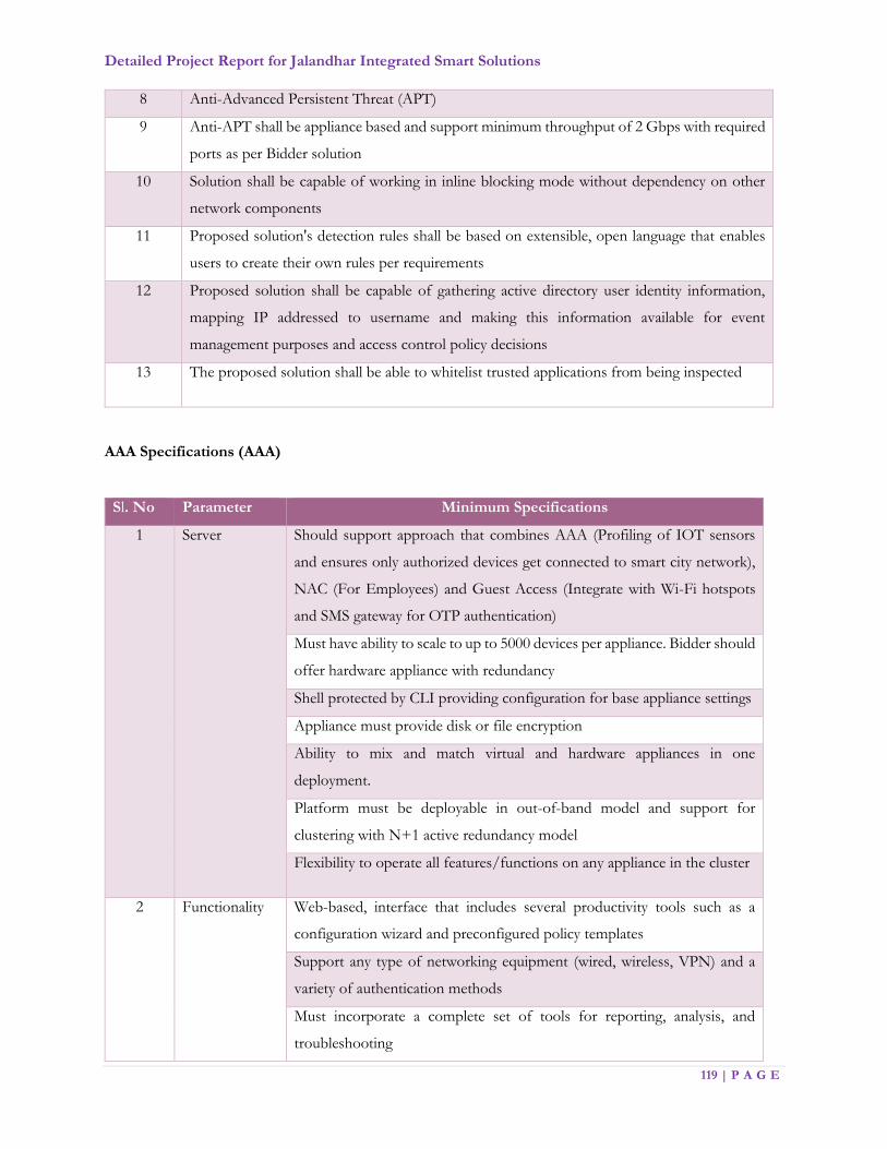
Detailed Project Report for Jalandhar Integrated Smart Solutions
119 | P A G E
8 Anti-Advanced Persistent Threat (APT)
9 Anti-APT shall be appliance based and support minimum throughput of 2 Gbps with required
ports as per Bidder solution
10 Solution shall be capable of working in inline blocking mode without dependency on other
network components
11 Proposed solution's detection rules shall be based on extensible, open language that enables
users to create their own rules per requirements
12 Proposed solution shall be capable of gathering active directory user identity information,
mapping IP addressed to username and making this information available for event
management purposes and access control policy decisions
13 The proposed solution shall be able to whitelist trusted applications from being inspected
AAA Specifications (AAA)
Sl. No Parameter Minimum Specifications
1 Server Should support approach that combines AAA (Profiling of IOT sensors
and ensures only authorized devices get connected to smart city network),
NAC (For Employees) and Guest Access (Integrate with Wi-Fi hotspots
and SMS gateway for OTP authentication)
Must have ability to scale to up to 5000 devices per appliance. Bidder should
offer hardware appliance with redundancy
Shell protected by CLI providing configuration for base appliance settings
Appliance must provide disk or file encryption
Ability to mix and match virtual and hardware appliances in one
deployment.
Platform must be deployable in out-of-band model and support for
clustering with N+1 active redundancy model
Flexibility to operate all features/functions on any appliance in the cluster
2 Functionality Web-based, interface that includes several productivity tools such as a
configuration wizard and preconfigured policy templates
Support any type of networking equipment (wired, wireless, VPN) and a
variety of authentication methods
Must incorporate a complete set of tools for reporting, analysis, and
troubleshooting

Detailed Project Report for Jalandhar Integrated Smart Solutions
120 | P A G E
AAA server should have device profiling functionality for 5000 concurrent
devices from day 1 to enforce context aware policies
AAA server must support both functionality RADIUS server for client
device authentication and TACACS+ for network device authentication
and logging from day 1. Overlay component can be added to achieve both
functionality
3 Management The solution Must be an easy-to-deploy hardware platform that utilizes
identity based policies to secure network access and includes an integrated
set of capabilities bundled under one policy platform:
Built-in guest management and device/user on boarding
Web based management interface with Dashboard
Reporting and analysis with custom data filters
Data repository for user, device, transaction information
Rich policies using identity, device, health, or conditional elements
Deployment and implementation tools.
4 Licensing Must support flexible licensing model based on required functionality
Correlation of user, device, and authentication information for easier
troubleshooting, tracking etc.
AAA framework must allow for the complete separation of Authentication
and Authorization sources. For example, authentication against Active
Directory but authorize against an external SQL database
Should support multiple methods for device identification and profiling
such as:
• Network based, device profiler utilizing collection via SNMP, DHCP,
HTTP, AD, ActiveSync/DNS
• AAA solution should have an inbuilt Certificate server to generate
unique certificates and this need to push to android phones and IOS
devices
5 Access Enforce security policies by blocking, isolating, and repairing
noncompliant machines in a quarantine in future
• Location Based Access
• Time Based Access

Detailed Project Report for Jalandhar Integrated Smart Solutions
121 | P A G E
6 Security Must support complex PKI deployment where TLS authentication requires
validating client certificate from multiple CA trust chain. Must also support
AAA server certificate being signed by external CA whilst validating internal
PKI signed client certificates
AAA server should have licenses to support posture checking which
includes antivirus check, firewall check , network connection , USB devices
, Peer to Peer applications and auto remediation
7 Reliability /
Performance
Appliances have ability to be clustered in any combination via local and
remote network connections providing 1 million scale, redundancy, and
access load balancing
Failure of master node should not impact the ability for backup appliances
to continue servicing authentication traffic
Must support several deployment modes including centralized, distributed,
or mixed
8 Guest Access Must allow Self registration of Guest with Sponsor approval
Should support customizable guest pages to allow the web-developers to
create a page for the desired look and feel Access can be restricted based
on
- Time of Day
- Number of Devices
- Number of Sessions
- Amount of Data consumed - Device Type
Unique delivery of method of ‘guest user credentials'
- SMS
- SMS over SMTP
Solution should support 1000 guest user on boarding - Workflow can be
OTP, Sponsor based, receptionist based or social login
Sponsor approval based on boarding to ensure that no-one can provision a
device without an approval
Distributed Denial of Service (DDos)
Sl. No Minimum Specifications
System Stability and Reliability
1 The Vendor should guarantee the stability and the reliability of hardware system such as CPU,
memory, interface, and software like OS

Detailed Project Report for Jalandhar Integrated Smart Solutions
122 | P A G E
2 The proposed Equipment must make sure the DDOS mitigation devices can work independently
when there is any problem happened in the DDOS detector
3 The proposed Equipment shall be appliance based with fully hardened and secured Operating
System (OS
System Functions and Requirement
4 The proposed Equipment shall support 10GE SFP+ port and 1 x Console port
5 Mitigation capacity of System should be at least 20Gbps
6 System should support service availability through functions of service monitoring and protection
from DDoS traffic
7 System should be stable and not affect service availability even upon any system fault
8 System should support ‘Troubleshooting function’ for each system function
9 System should provide in-line mode and Diversion(off ramping)/Reinjection(on ramping) mode
for detecting and protecting DDoS traffic
10 System should detect any DDoS traffic and mitigate any DDoS attack without interrupt legitimate
traffic and customer services
11 The Proposed system must be able to detect volumetric DDOS traffic and start mitigate
volumetric DDOS traffic within 3 min
12 System should provide IP reputation list protection to filter blacklisted IP.
13 Systems should consists of Detector, Mitigator and Management device
14 System should provide user defined signatures
15 System should support detection and protection of DDoS traffic as below:
IP Spoofed/Non-spoofed TCP Syn Flooding
IP Spoofed/Non-spoofed TCP Syn-ACK Flooding
IP Spoofed/Non-spoofed TCP FIN Flooding
IP Spoofed/Non-spoofed UDP Flooding
IP Spoofed/Non-spoofed ICMP Flooding
HTTP GET Flooding
HTTP POST Flooding
HTTPS Flooding
DNS Query Flooding
SIP Flooding
DNS amplification
NTP amplification
SSDP amplification
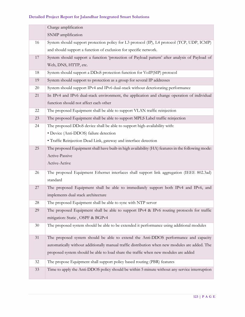
Detailed Project Report for Jalandhar Integrated Smart Solutions
123 | P A G E
Charge amplification
SNMP amplification
16 System should support protection policy for L3 protocol (IP), L4 protocol (TCP, UDP, ICMP)
and should support a function of exclusion for specific network.
17 System should support a function ‘protection of Payload pattern’ after analysis of Payload of
Web, DNS, HTTP, etc.
18 System should support a DDoS protection function for VoIP(SIP) protocol
19 System should support to protection as a group for several IP addresses
20 System should support IPv4 and IPv6 dual-stack without deteriorating performance
21 In IPv4 and IPv6 dual-stack environment, the application and change operation of individual
function should not affect each other
22 The proposed Equipment shall be able to support VLAN traffic reinjection
23 The proposed Equipment shall be able to support MPLS Label traffic reinjection
24 The proposed DDoS device shall be able to support high-availability with:
• Device (Anti-DDOS) failure detection
• Traffic Reinjection Dead Link, gateway and interface detection
25 The proposed Equipment shall have built-in high availability (HA) features in the following mode:
Active-Passive
Active-Active
26 The proposed Equipment Ethernet interfaces shall support link aggregation (IEEE 802.3ad)
standard
27 The proposed Equipment shall be able to immediately support both IPv4 and IPv6, and
implements dual stack architecture
28 The proposed Equipment shall be able to sync with NTP server
29 The proposed Equipment shall be able to support IPv4 & IPv6 routing protocols for traffic
mitigation: Static , OSPF & BGPv4
30 The proposed system should be able to be extended it performance using additional modules
31 The proposed system should be able to extend the Anti-DDOS performance and capacity
automatically without additionally manual traffic distribution when new modules are added. The
proposed system should be able to load share the traffic when new modules are added
32 The propose Equipment shall support policy based routing (PBR) features
33 Time to apply the Anti-DDOS policy should be within 5 minute without any service interruption
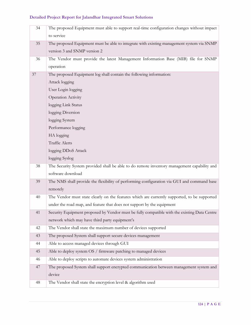
Detailed Project Report for Jalandhar Integrated Smart Solutions
124 | P A G E
34 The proposed Equipment must able to support real-time configuration changes without impact
to service
35 The proposed Equipment must be able to integrate with existing management system via SNMP
version 3 and SNMP version 2
36 The Vendor must provide the latest Management Information Base (MIB) file for SNMP
operation
37 The proposed Equipment log shall contain the following information:
Attack logging
User Login logging
Operation Activity
logging Link Status
logging Diversion
logging System
Performance logging
HA logging
Traffic Alerts
logging DDoS Attack
logging Syslog
38 The Security System provided shall be able to do remote inventory management capability and
software download
39 The NMS shall provide the flexibility of performing configuration via GUI and command base
remotely
40 The Vendor must state clearly on the features which are currently supported, to be supported
under the road map, and feature that does not support by the equipment
41 Security Equipment proposed by Vendor must be fully compatible with the existing Data Centre
network which may have third party equipment’s
42 The Vendor shall state the maximum number of devices supported
43 The proposed System shall support secure devices management
44 Able to access managed devices through GUI
45 Able to deploy system OS / firmware patching to managed devices
46 Able to deploy scripts to automate devices system administration
47 The proposed System shall support encrypted communication between management system and
device
48 The Vendor shall state the encryption level & algorithm used
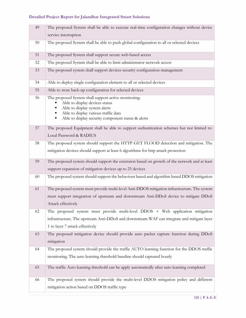
Detailed Project Report for Jalandhar Integrated Smart Solutions
125 | P A G E
49 The proposed System shall be able to execute real-time configuration changes without device
service interruption
50 The proposed System shall be able to push global configuration to all or selected devices
51 The proposed System shall support secure web-based access
52 The proposed System shall be able to limit administrator network access
53 The proposed system shall support devices security configuration management
54 Able to deploy single configuration element to all or selected devices
55 Able to store back-up configuration for selected devices
56 The proposed System shall support active monitoring:
Able to display devices status
Able to display system alerts
Able to display various traffic data
Able to display security component status & alerts
57 The proposed Equipment shall be able to support authentication schemes but not limited to:
Local Password & RADIUS
58 The proposed system should support the HTTP GET FLOOD detection and mitigation. The
mitigation devices should support at least 6 algorithms for http attack protection
59 The proposed system should support the extension based on growth of the network and at least
support expansion of mitigation devices up to 25 devices
60 The proposed system should support the behaviour based and algorithm based DDOS mitigation
61 The proposed system must provide multi-level Anti-DDOS mitigation infrastructure. The system
must support integration of upstream and downstream Anti-DDoS device to mitigate DDoS
Attack effectively
62 The proposed system must provide multi-level DDOS + Web application mitigation
infrastructure. The upstream Anti-DDoS and downstream WAF can integrate and mitigate layer
1 to layer 7 attack effectively
63 The proposed mitigation device should provide auto packet capture function during DDoS
mitigation
64 The proposed system should provide the traffic AUTO learning function for the DDOS traffic
monitoring. The auto learning threshold baseline should captured hourly
65 The traffic Auto learning threshold can be apply automatically after auto learning completed
66 The proposed system should provide the multi-level DDOS mitigation policy and different
mitigation action based on DDOS traffic type
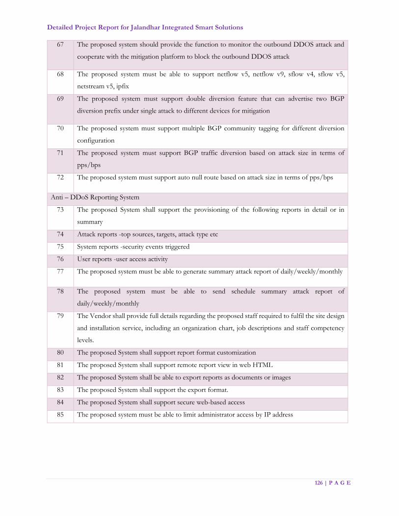
Detailed Project Report for Jalandhar Integrated Smart Solutions
126 | P A G E
67 The proposed system should provide the function to monitor the outbound DDOS attack and
cooperate with the mitigation platform to block the outbound DDOS attack
68 The proposed system must be able to support netflow v5, netflow v9, sflow v4, sflow v5,
netstream v5, ipfix
69 The proposed system must support double diversion feature that can advertise two BGP
diversion prefix under single attack to different devices for mitigation
70 The proposed system must support multiple BGP community tagging for different diversion
configuration
71 The proposed system must support BGP traffic diversion based on attack size in terms of
pps/bps
72 The proposed system must support auto null route based on attack size in terms of pps/bps
Anti – DDoS Reporting System
73 The proposed System shall support the provisioning of the following reports in detail or in
summary
74 Attack reports -top sources, targets, attack type etc
75 System reports -security events triggered
76 User reports -user access activity
77 The proposed system must be able to generate summary attack report of daily/weekly/monthly
78 The proposed system must be able to send schedule summary attack report of
daily/weekly/monthly
79 The Vendor shall provide full details regarding the proposed staff required to fulfil the site design
and installation service, including an organization chart, job descriptions and staff competency
levels.
80 The proposed System shall support report format customization
81 The proposed System shall support remote report view in web HTML
82 The proposed System shall be able to export reports as documents or images
83 The proposed System shall support the export format.
84 The proposed System shall support secure web-based access
85 The proposed system must be able to limit administrator access by IP address

Detailed Project Report for Jalandhar Integrated Smart Solutions
127 | P A G E
Anti-Virus Solution
The following features are required for centralized anti-virus solution, to protect all computing
resources (servers, desktops, other edge level devices, etc.)
1. Ability to scan through all file types and various compression formats.
2. Ability to scan HTML, VBScript Viruses, malicious applets and ActiveX controls.
3. Must update itself over internet for virus definitions, program updates etc. (periodically as well
as in push-updates in case of outbreaks)
4. Able to perform different scan Actions based on the virus type (Trojan/ Worm, Joke, Hoax,
Virus, other)
5. Shall provide Real-time Product Performance Monitor and Built-in Debug and Diagnostic
tools, and context- sensitive help.
6. The solution must provide protection to multiple remote clients
7. Shall provide for virus notification options for Virus Outbreak Alert and other configurable
Conditional Notification.
8. Should be capable of providing multiple layers of defence.
9. Shall have facility to clean, delete and quarantine the virus affect files.
10. Should support online update, where by most product updates and patches can be perform
without bringing messaging server off-line.
Enterprise Management System (EMS)
Sl. No. Parameter Minimum specifications
1 SLA & Contract
Management System
It must be a centralized monitoring solution for all IT assets
(including servers, network equipment etc.).
The solution must have integrated dashboard providing view
of non performing components/issues with related to service
on any active components. The solution must follow
governance, compliance and content validations to improve
standardization of service level contracts.

Detailed Project Report for Jalandhar Integrated Smart Solutions
128 | P A G E
Application should be pre-configured so as to allow the users
to generate timely reports on the SLAs on various parameters.
The solution must support Service Level Agreements &
Lifecycle Management including Version Control, Status
Control, Effectively and audit Trail to ensure accountability for
the project.
The solution must have the ability to define and calculate key
performance indicators from an End to End Business Service
delivery perspective related to JICCC Project under discussion.
The solution should support requirements of the auditors
requiring technical audit of the whole system which MSI should
allow the auditors to access the system.
The solution must have an integrated dashboard, view of
Contract Parties & current SLA delivery levels and view of
Services & current SLA performance.
The solution should support SLA Alerts escalation and
approval process. Solution should support effective root-cause
analysis, support capabilities for investigating the root causes
of failed service levels and must make it possible to find the
underlying events that cause the service level contract to fail.
Accept Data from a variety of formats. Support for Defining
and Calculating Service Credit and Penalty based on clauses in
SLAs.
Reporting: -
• Ability to generate reports on penalty and credit due, to check
on non-compliance of SLAs for the JICCC project
• Monetary penalties to be levied for non-compliance of SLA,
thus the system must provide Service Level Performance
Report over time, contract, service and more.
• The solution should provide historical and concurrent service
level reports for the surveillance project in order to ensure
accountability of the service provider’s performance
• Automatic Report creation, execution and Scheduling, must
support variety of export formats including Microsoft Word,
Adobe, PDF etc.
• The solution must support Templates for report generation,

Detailed Project Report for Jalandhar Integrated Smart Solutions
129 | P A G E
Report Filtering and Consolidation and Context sensitive
Drill-down on specific report data to drive standardization
and governance of the JICCC project
• The solution must support security for drill-down
capabilities in dashboard reports ensuring visibility for only
relevant personnel of the JICCC project
• Support real-time reports (like at-a-glance status) as well as
historical analysis reports (like Trend, TopN, Capacity
planning reports etc.)
2 Network
Monitoring System
The Solution should provide capability to monitor any device
based on SNMP v1, v2c & 3
The Solution should monitor bandwidth utilization.
The solution should monitor utilization based on bandwidth
The Solution must be capable of monitoring the availability,
health, and performance of core networking devices including
but not limited to CPU, memory, temperature.
The Solution should have the ability to issues pings to check
on availability of ports, devices.
The Ping Monitoring should also support collection of packet
loss, Latency and Jitters during ICMP Ping Checks
The Port Check for IP Services monitoring should also provide
mechanism to define new services and ability to send custom
commands during port check mechanism.
The Solution should have the ability to receive SNMP traps and
syslog.
The Solution should automatically collect and store historical
data so users can view and understand network performance
trends. The solution should be capable of monitoring network
delay/latency.
The solution should be capable of monitoring delay variation
The solution should be capable of monitoring packet loss,
Packet QOS, Packet Errors on one or more ports
The solution should allow users to access network availability
and performance reports via the web or have those delivered
via e-mail.

Detailed Project Report for Jalandhar Integrated Smart Solutions
130 | P A G E
The solution should support auto-discovery of network devices
The solution should have the ability to schedule regular
rediscovery of subnets.
The solution should provide the ability to visually represent
LAN/WAN links) with displays of related real-time
performance data including utilizations.
The system should provide discovery of heterogeneous
physical network devices like Layer-2 & Layer-3 switches,
Routers and other IP devices and do mapping of LAN & WAN
connectivity.
The System shall support monitoring of Syslog
The solution should provide capability to add an IP device or
IP Range or IP subnet with functionality supporting multiple
SNMP strings.
The solutions should have real time, detect configuration and
asset information changes made across a multi-vendor device
network, regardless of how each change is made and also
support configuration deployment/rollback and configuration
templates.
3 Server Performance
Monitoring System
The proposed tool should integrate with network performance
management system and support operating system monitoring
for various platforms supplied as part of the Surveillance
Project. The proposed tool must provide information about
availability and performance for target server nodes. The
proposed tool should be able to monitor various operating
system parameters such as processors, memory, files,
processes, file systems, etc. where applicable.
The solution should provide a unified web based console,
which consolidates all aspects of role based access under a
single console. Proposed Network Management shall integrate
with SLA & Contract Management system in order to supply
KPI metrics like availability, utilization, and performance in
order to measure central SLA’s and calculate penalties

Detailed Project Report for Jalandhar Integrated Smart Solutions
131 | P A G E
4 Application
Performance
Management
The solution should measure the end users' experiences based
on transactions without the need to install agents on user
desktops.
The solution must be able to provide user usage analysis and
show how user's success rate, average time and transaction
count has changed over a specific period of time such as
current week versus previous week.
The solution must be able to provide the ability to detect and
alert when users experience HTTP error codes such as 404
errors or errors coming from the web application.
Solution shall be able to monitor customer transaction by end-
user name, and thus able to understand exactly which
customers were impacted, their location, type of browser used
etc.
The solution must simplify complex app topologies through
task–relevant views based on attributes such as location,
business unit, application component etc.
The solution must speed up the process of triage by showing
the impact of change, thus enabling to easily locate where
performance problems originate.
The solution should provide the flexibility of collecting deep-
dive diagnostics data for the transactions that matter for triage
as opposed to collecting deep-dive data for every transaction.
The solution must proactively monitor 100% of real user
transactions; detect failed transactions; gather evidence
necessary for triage and diagnosis of problems that affect user
experiences and prevent completion of critical business
processes.
The solution must determine if the root cause of performance
issues is inside the monitored application, in connected back-
end systems or at the network layer from a single console view.
The solution must provide proactive real-time insights into real
user behaviour, trends, log analytics and performance to
enhance customer experience across various channels

Detailed Project Report for Jalandhar Integrated Smart Solutions
132 | P A G E
The solution must provide operational efficiency capabilities
that provide insight of app performance by version, geo, OS,
network, real-time alerts on threshold violations impacting
SLAs and prioritize alerts based on impact to business, revenue
and gain end- to-end visibility into the mobile infrastructure.
The solution must provide complete Insights into Application
Flows, Heat Maps to enable improving the UI design,
understand user interactions, build functionality based on real
user data and create product & services differentiation.
6 Asset Management
System
Ability to provide inventory of hardware and software
applications on end-user desktops, including information on
processor, memory, OS, mouse, keyboard, etc. through agents
installed on them.
Ability to have reporting capabilities; provide predefined
reports and ability to create customized reports on data in the
inventory database. Report results could be displayed as lists or
graphs.
Ability to provide the facility to collect custom information
from desktops.
Ability to provide facility to recognize custom applications on
desktops.
Facility for the administrator to register a new application to
the detectable application list using certain identification
criteria. Shall enable the new application to be detected
automatically next time the inventory is scanned.
Ability to support configuration management functionality
using which standardization of configuration can be achieved
of all the desktops.
Software metering shall be supported to audit and control
software usage. Shall support offline and online metering.
Ability to support dynamic grouping of enabling assets to be
grouped dynamically based on some pre-defined criteria e.g. a
group shall be able to display how many and which computers
has a specific application installed. As and when a new

Detailed Project Report for Jalandhar Integrated Smart Solutions
133 | P A G E
computer gets the new application installed it shall dynamically
add to the group.
Ability to use the query tool to identify specific instances of
concern like policy violation (presence of prohibited programs
/ games and old versions, etc.), inventory changes (memory
change, etc.) and accordingly it could perform several actions
as reply. These actions may be (a) sending a mail, (b) writing to
file (c) message to scroll on monitor screen, etc.
Facility to track changes by maintaining history of an asset.
The proposed EMS solution shall provide comprehensive and
end -to-end management of all the components for each
service including all the hardware devices, Network, Systems
and Application infrastructure.
Note: It is mandatory that all the modules for the proposed EMS
Solution shall provide out-of-the-box and seamless integration
capabilities. SI shall provide the specifications and numbers for all
necessary Hardware, OS & DB (if any) which is required for an EMS to
operate effectively.
Network Management System (Open Source)
The NMS should support an open database schema, configuration, administration, monitoring and
troubleshooting of Switches, guided workflows based on best practices with built‐in configuration
templates, the capability to view the network topology, Layer 2 Services and Fault Management
It should support rich visibility into end‐user connectivity
The NMS should automatically discover IP devices, SNMP compliant network devices on the network
The NMS should support Inventory management of Network devices, should support Monitoring and
troubleshooting of Devices, should support configuration management and reporting.
The NMS should support Inventory management of Network devices, should support Monitoring and
troubleshooting of Devices, should support configuration management and
The NMS should support flexible reporting for inventory, user tracking, compliance, switch port usage
and end‐of‐sale
Must show location information of clients, infrastructure Access Points, Rogue Access Points in a map
format
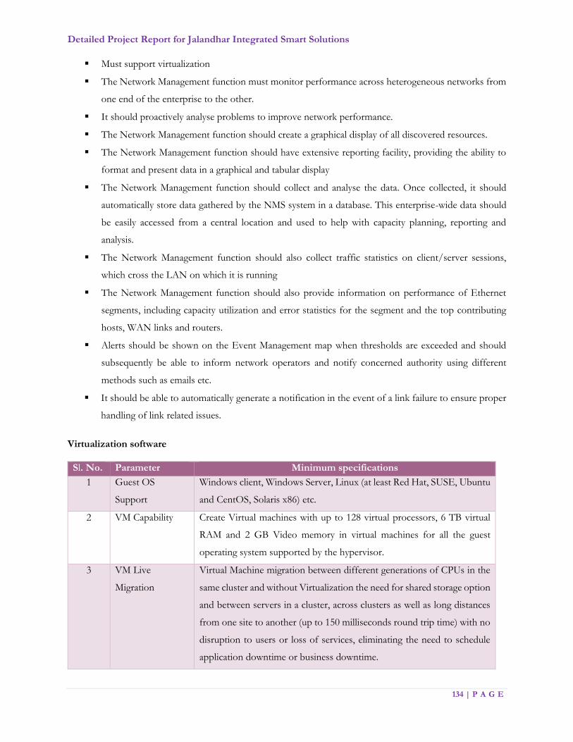
Detailed Project Report for Jalandhar Integrated Smart Solutions
134 | P A G E
Must support virtualization
The Network Management function must monitor performance across heterogeneous networks from
one end of the enterprise to the other.
It should proactively analyse problems to improve network performance.
The Network Management function should create a graphical display of all discovered resources.
The Network Management function should have extensive reporting facility, providing the ability to
format and present data in a graphical and tabular display
The Network Management function should collect and analyse the data. Once collected, it should
automatically store data gathered by the NMS system in a database. This enterprise-wide data should
be easily accessed from a central location and used to help with capacity planning, reporting and
analysis.
The Network Management function should also collect traffic statistics on client/server sessions,
which cross the LAN on which it is running
The Network Management function should also provide information on performance of Ethernet
segments, including capacity utilization and error statistics for the segment and the top contributing
hosts, WAN links and routers.
Alerts should be shown on the Event Management map when thresholds are exceeded and should
subsequently be able to inform network operators and notify concerned authority using different
methods such as emails etc.
It should be able to automatically generate a notification in the event of a link failure to ensure proper
handling of link related issues.
Virtualization software
Sl. No. Parameter Minimum specifications
1 Guest OS
Support
Windows client, Windows Server, Linux (at least Red Hat, SUSE, Ubuntu
and CentOS, Solaris x86) etc.
2 VM Capability Create Virtual machines with up to 128 virtual processors, 6 TB virtual
RAM and 2 GB Video memory in virtual machines for all the guest
operating system supported by the hypervisor.
3 VM Live
Migration
Virtual Machine migration between different generations of CPUs in the
same cluster and without Virtualization the need for shared storage option
and between servers in a cluster, across clusters as well as long distances
from one site to another (up to 150 milliseconds round trip time) with no
disruption to users or loss of services, eliminating the need to schedule
application downtime or business downtime.
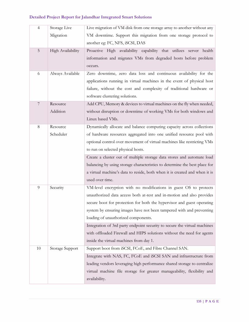
Detailed Project Report for Jalandhar Integrated Smart Solutions
135 | P A G E
4 Storage Live
Migration
Live migration of VM disk from one storage array to another without any
VM downtime. Support this migration from one storage protocol to
another eg: FC, NFS, iSCSI, DAS
5 High Availability Proactive High availability capability that utilizes server health
information and migrates VMs from degraded hosts before problem
occurs.
6 Always Available Zero downtime, zero data loss and continuous availability for the
applications running in virtual machines in the event of physical host
failure, without the cost and complexity of traditional hardware or
software clustering solutions.
7 Resource
Addition
Add CPU, Memory & devices to virtual machines on the fly when needed,
without disruption or downtime of working VMs for both windows and
Linux based VMs.
8 Resource
Scheduler
Dynamically allocate and balance computing capacity across collections
of hardware resources aggregated into one unified resource pool with
optional control over movement of virtual machines like restricting VMs
to run on selected physical hosts.
Create a cluster out of multiple storage data stores and automate load
balancing by using storage characteristics to determine the best place for
a virtual machine’s data to reside, both when it is created and when it is
used over time.
9 Security VM-level encryption with no modifications in guest OS to protects
unauthorized data access both at-rest and in-motion and also provides
secure boot for protection for both the hypervisor and guest operating
system by ensuring images have not been tampered with and preventing
loading of unauthorized components.
Integration of 3rd party endpoint security to secure the virtual machines
with offloaded Firewall and HIPS solutions without the need for agents
inside the virtual machines from day 1.
10 Storage Support Support boot from iSCSI, FCoE, and Fibre Channel SAN.
Integrate with NAS, FC, FCoE and iSCSI SAN and infrastructure from
leading vendors leveraging high performance shared storage to centralize
virtual machine file storage for greater manageability, flexibility and
availability.
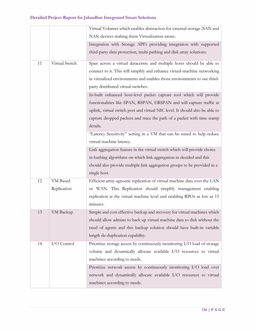
Detailed Project Report for Jalandhar Integrated Smart Solutions
136 | P A G E
Virtual Volumes which enables abstraction for external storage (SAN and
NAS) devices making them Virtualization aware.
Integration with Storage API's providing integration with supported
third-party data protection, multi-pathing and disk array solutions.
11 Virtual Switch Span across a virtual datacentre and multiple hosts should be able to
connect to it. This will simplify and enhance virtual-machine networking
in virtualized environments and enables those environments to use third-
party distributed virtual switches.
In-built enhanced host-level packet capture tool which will provide
functionalities like SPAN, RSPAN, ERSPAN and will capture traffic at
uplink, virtual switch port and virtual NIC level. It should also be able to
capture dropped packets and trace the path of a packet with time stamp
details.
“Latency Sensitivity” setting in a VM that can be tuned to help reduce
virtual machine latency.
Link aggregation feature in the virtual switch which will provide choice
in hashing algorithms on which link aggregation in decided and this
should also provide multiple link aggregation groups to be provided in a
single host.
12 VM Based
Replication
Efficient array-agnostic replication of virtual machine data over the LAN
or WAN. This Replication should simplify management enabling
replication at the virtual machine level and enabling RPOs as low as 15
minutes.
13 VM Backup Simple and cost effective backup and recovery for virtual machines which
should allow admins to back up virtual machine data to disk without the
need of agents and this backup solution should have built-in variable
length de-duplication capability.
14 I/O Control Prioritize storage access by continuously monitoring I/O load of storage
volume and dynamically allocate available I/O resources to virtual
machines according to needs.
Prioritize network access by continuously monitoring I/O load over
network and dynamically allocate available I/O resources to virtual
machines according to needs.

Detailed Project Report for Jalandhar Integrated Smart Solutions
137 | P A G E
15 OEM Support Direct OEM 24x7x365 days with unlimited incident support and 30mins
or less response time including the unlimited upgrades and updates.
Databases
Any commercially available database (e.g., SQL or equivalent), shall be provided along with license and
support and upgrade costs
Sl. No. Minimum specifications
General
1 Database License should be un-restricted, to prevent any non-compliance in an event of
customization & integration.
2 Database should provide Unicode (Latest version) capability with Indian language support
3 Databases shall support multi hardware and Operating System platform.
4 Database shall provide standard access Tool for administering the database. The tool should
be able to monitor, maintain and manage the database instance, objects, and packages.
5 Database shall have built-in backup and recovery tool, which can support the online backup.
6 Database shall be able to provide database level storage management mechanism, which
should enable the availability by means of creating redundancy, automatically balance the data
files across the available disks, i/o balancing across the available disks for the database for
performance, availability and management.
8 Should be an enterprise class database with the ability to support connection pooling, load
sharing and load balancing when the load on the application increases.
9 Database shall provide native functionality to store XML, within the database and support
search, query functionalities.
10 Database shall have built-in DR solution to replicate the changes happening in the database
across DR site with an option to run real-time reports from the DR site without stopping the
recovery mechanism
11 Database shall have Active-Passive failover clustering with objectives of scalability and high
availability.
12 Database shall provide mechanism to recover rows, tables when accidentally deleted. The
mechanism should provide ways and means of recovering the database.
13 Database shall provide functionality to replicate / propagate the data across different
databases.
14 The RDBMS should support partitioning feature in table level object.

Detailed Project Report for Jalandhar Integrated Smart Solutions
138 | P A G E
15 Database shall provide native functionality to store XML, Images, Text, Medical Images,
CAD images within the database and support search, query functionalities.
16 Database shall include tools for enterprise class high availability solution like monitoring
performance, diagnose and alert for problems, tuning bottlenecks, resource monitoring and
automatic resource allocation capabilities.
17 RDBMS must support the SQL queries.
18 Database shall provide security mechanism at foundation level of the database, so that the
options and additions to the database confirm the security policy of the organization without
changing the application code. Shall confirm to security evaluations and conformance to
common criteria.
19 Database shall provide control data access down to the row-level so that multiple users with
varying access privileges can share the data within the same physical database.
20 Database shall support for enhanced authentication by integrating tokens and biometric
technologies.
21 Database shall provide functionality for classifying data and mediating access to data based
on its classification for multi-level security and mandatory access control, manage access to
data on a "need to know" basis.
22 Database shall be having native auditing capabilities for the database. Should support optional
Audit Capability to store the audit records in separate audit store with monitoring & reporting
for multiple databases to detect any security breaches.
23 Database shall be having built-in provision to Administer database / database clusters,
Monitor performance, Maintain database, Backup and recovery, Recovery management,
Disaster recovery management.
24
The Management tool should provide advisory-based performance tuning tool which help to
tune the queries or objects, SQL analysis, SQL access.
25 The enterprise database should provide single web-based console for management of the
database.
Restart and Recovery
26 Availability of recovery/restart facilities of the DBMS.
27 Automated recovery/restart features provided that do not require programmer involvement
or system reruns.
30 Program restart should be provided from the point of failure.
31 Ability to manage recovery/restart facilities to reduce system overhead.
32 Provides extra utilities to back up the databases by faster means than record by record
retrieval.

Detailed Project Report for Jalandhar Integrated Smart Solutions
139 | P A G E
33 Provides clear error reporting, recovery and logging.
34 Describe recovery strategies that needs to be in place.
35 System should support mirroring for DRP.
Backup Procedures
36 Describe Backup Procedures you plan to deploy.
37 Describe backup application(s) your proposed solution use.
38 Provide details of data backup and restore processes and procedures for all data elements.
39 Provide details of automated archiving procedures to copy active data to storage media when
archive 'age' is reached.
Error Handling
40 Ability to trap a transaction failure through:
• Application Software
• DBMS
• Availability of manual containing all system error messages and correction procedures
System Control
41 Provide details of the 'Audit trail' facility for your proposed solution.
42 Should provide adequate auditing trail facility.
43 System should record the date and time stamp for all records.
44 Ability to track terminals from where the system is accessed.
Video Conferencing System
Video Conferencing System – General Requirements
Sl. No. Parameter Minimum Specifications
1 System
Features
Conferencing System should have minimum 20 ports at HD/ 1080p, 25fps or
better on IP in continuous presence mode with H.265 resolution or better and
encryption
Multi-point video Conferencing Solution should be capable of offering a High
Definition/1080p, 25fps or better in real-time for at least 15 number of
concurrent ports/systems in single call or multiple multi-party sessions in
continuous presence and voice activation mode with minimum bandwidth
utilisation
It should as well provide network flexibility for a reliable distributed
architecture and cost-effective scalability for future requirements.

Detailed Project Report for Jalandhar Integrated Smart Solutions
140 | P A G E
Conferencing System should be deployed in High Availability and should be
redundant (1:1)
It should provide flexibility to the users, where users can join the video
conference call using PC, laptop, Smart phones, PSTN but not limited to.
Video conferencing system shall support various browsers installed in PC,
Laptop, Smartphones etc. This facility should be available from day one.
The systems should support document sharing (PC images, etc.).
2 Video
Standards
and
Resolutions
It should support WebRTC and latest industry standards for video
compression.
3 Content
Standards
and
Resolutions
Content sharing should be possible at 1080p 25fps
It should support H.239 and encryption in SIP & H.323 modes
4 Audio
Standards
and Features
It should support G.711, G.722, G.722.1
It shall support aspect ratio of 16:9 and 4:3.
It shall support a mix of resolutions in both Voice-activated mode and
Continuous Presence. Each endpoint shall receive at the maximum of its
capacity without reducing the capacity of another.
Dynamic CP layout adjustment (it will choose the best video layout according
to the number of participants in the conference).
It should support distributed architecture with intelligent and automatic call
routing. It must support load balancing such that in case there are two
instances, conference participants can get distributed across these two
instances based on their locations and still join into the same conference.
5 Network and
security
features
It shall support encryption of 128 bit for every participant without affecting
any other feature, functionality or port count.
6 Interoperabili
ty
Apart from Integrated video systems, video IP phones, normal IP phones also
should be able to join the conference seamlessly
7 General
Standards
Should be based on ITU's (International Telecommunication Union) standards
and guidelines.
Management & Scheduling
Sl. No. Component Minimum Specifications

Detailed Project Report for Jalandhar Integrated Smart Solutions
141 | P A G E
8 System The central management solution should be able to schedule the meeting
quickly and easily manage conference infrastructure device configuration and
provision of the endpoints.
9 System
Capacity
The Central management server must support 10 devices capacity from day
one and must be scalable.
10 Provisioning The administration should be able to configure individual end points or group
of endpoints using user policy from single management console.
It should be possible for the endpoint to automatically pull the device and
site provisioning information from the system while start up
11 Software
Update
It should support automatic and scheduled mechanism to upgrade the
software on one or more endpoints with a standard software.
12 Scheduling The system should support schedule video conference meetings.
13 Directory
Services
Should support integration with the corporate Active Directory for scheduling
the video conference calls.
The system should store video dialling information.
Voice and Video Call Control
Sl. No. Parameter Minimum Specifications
14 System The Call control solution should be able to register Integrated VC room
system, Video IP phones, normal IP phones natively.
The system should be a converged communication System with ability to run
TDM and IP on the same platform.
It should be possible to deploy Servers / Call Servers in an active-active/active
hot-standby configuration over the distributed IP infrastructure (LAN/WAN).
The communication feature server and gateway should support IP V6 from
day one so as to be future proof
The offered solution must provide a standard based mechanism for QoS
implementation
Should support AD & LDAP integration for directory synchronization & user
authentication
15 Support for
call-
processing
and call-
control
Should support signalling standards/Protocols – SIP, MGCP, H.323, Q.Sig
Voice Codec support - G.711, G.729, G.729ab, g.722, ILBC. Video codecs:
H.261, H.263, H.264, H.265 and Wideband Video Codec
Video telephony support
System should be supplied with 50 endpoint license
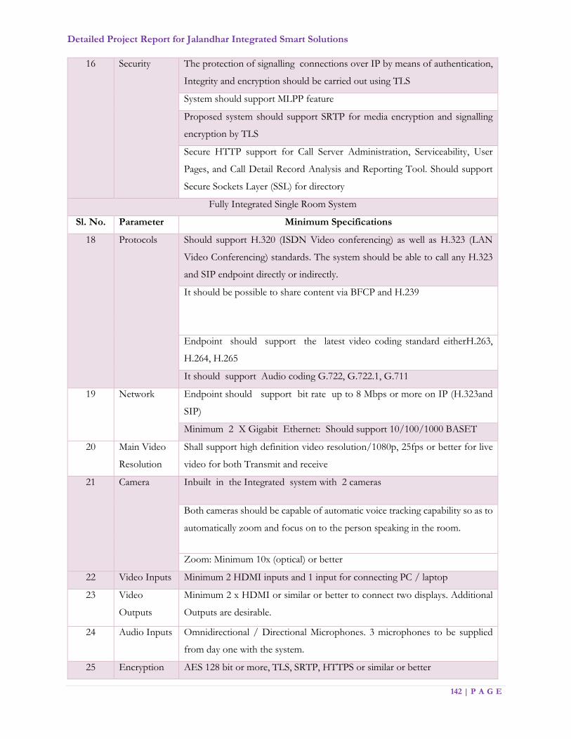
Detailed Project Report for Jalandhar Integrated Smart Solutions
142 | P A G E
16 Security The protection of signalling connections over IP by means of authentication,
Integrity and encryption should be carried out using TLS
System should support MLPP feature
Proposed system should support SRTP for media encryption and signalling
encryption by TLS
Secure HTTP support for Call Server Administration, Serviceability, User
Pages, and Call Detail Record Analysis and Reporting Tool. Should support
Secure Sockets Layer (SSL) for directory
Fully Integrated Single Room System
Sl. No. Parameter Minimum Specifications
18 Protocols Should support H.320 (ISDN Video conferencing) as well as H.323 (LAN
Video Conferencing) standards. The system should be able to call any H.323
and SIP endpoint directly or indirectly.
It should be possible to share content via BFCP and H.239
Endpoint should support the latest video coding standard eitherH.263,
H.264, H.265
It should support Audio coding G.722, G.722.1, G.711
19 Network Endpoint should support bit rate up to 8 Mbps or more on IP (H.323and
SIP)
Minimum 2 X Gigabit Ethernet: Should support 10/100/1000 BASET
20 Main Video
Resolution
Shall support high definition video resolution/1080p, 25fps or better for live
video for both Transmit and receive
21 Camera Inbuilt in the Integrated system with 2 cameras
Both cameras should be capable of automatic voice tracking capability so as to
automatically zoom and focus on to the person speaking in the room.
Zoom: Minimum 10x (optical) or better
22 Video Inputs Minimum 2 HDMI inputs and 1 input for connecting PC / laptop
23 Video
Outputs
Minimum 2 x HDMI or similar or better to connect two displays. Additional
Outputs are desirable.
24 Audio Inputs Omnidirectional / Directional Microphones. 3 microphones to be supplied
from day one with the system.
25 Encryption AES 128 bit or more, TLS, SRTP, HTTPS or similar or better

Detailed Project Report for Jalandhar Integrated Smart Solutions
143 | P A G E
26 User
Interface
Intuitive touch panel to operate the entire system
Video device
Sl. No. Parameter Minimum Specifications
27 System Should be an integrated system with at least 50-inch LCD/TFT screen, 1080P
resolution (16:9), HD camera and speakers for wideband audio output. The
Codec should be a part of the unit.
The LCD/TFT screen should be remote control operatable.
Video Standards:
• Minimum H.264 and above
• The system should support SIP protocol
• Must support desktop sharing SIP calls
Video Frame Rate: Must support 1080p 25 fps
Video Input: Should have HDMI or DVI (Digital Video Interface) input to
connect PC/Laptop directly to the Video conferencing system and display a
resolution of XGA/SXGA. The user must be able to toggle between the
Laptop/PC mode and the Video conferencing mode at a push of button/icon.
Video Output: Must have an HD output via an HDMI/DVI output port to
display the VC screen onto an external display
Should have inbuilt microphone & speaker system.
28 Security Security - Password protected system menu
29 Camera Should be HD at least 6-megapixel camera, with privacy shutter
Must support 1080p resolution. Should support Wide formats. Must support
1920 X 1080 resolution
The VC unit must allow the camera to be used as a document camera to
capture hard copies and transmit it to the far end site
EPABX
Operational Requirements
1. The control room shall be equipped with EPABX comprising of at least 1 PRI line hunting
- single telephone number to a group of at least 30 lines.
2. The Control room shall have seating capacity of minimum of 30 operators. Citizen can dial
the telephone no. for any complaints related with police/ambulance/fire/Municipal
Detailed Project Report for Jalandhar Integrated Smart Solutions
144 | P A G E
Corporation. The system shall have capability to display name, address and find the
geographical position of the caller at the time of receiving call in call center.
3. All phone calls shall be recorded for future references. The phone calls of at least the last 6
months shall be stored.
4. The operators shall be able to receive call, dispatch calls, use GIS maps and can send the alerts
to the nearby free patrolling vehicles / fire engines / ambulances and inform the nearest Police
Station about the event.
5. The operator shall be able to view the nearest Fire Station, Hospital, Blood Bank for providing
additional assistance at the site of incident.
6. A web-based incident analytic software shall be made available that will help the Police /
Ambulance / Fire / Municipal Corporation to do detailed analysis and analytics so that the
response can be made proactive and the effectiveness of the service improved.
7. After the Call has been logged in by the call taker, the system shall send a SMS to the Caller
stating the CFS/Tracking Number along with a password as acknowledgement to the call
made to the control room. The caller can use this number on department website to access
the event progress details such as Action Taken Reports (ATR), file attachments, remarks, or
other information’s as per the prevailing departmental policy for data sharing.
8. Security and Audit - The platform needs to be audited with STQC certification by CERT-IN
empanelled agency.
9. Multi-Language & Differently abled person Support - Should have support for local Indian
languages to be able to reach masses. Shall provide support for English and Hindi, standard
local languages (Punjabi) across various channels (SMS, IVR, Smart Client, Mobile Web etc.)
for services across service categories as required by individual integrating departments.
a. Policies for retention of records including voice recording screen recording, case details
etc.
b. Records would be deleted in consultation with the department.

Detailed Project Report for Jalandhar Integrated Smart Solutions
145 | P A G E
Video Wall
Sl. No. Parameter Minimum Specifications
1 Size JICCC Screen unit size- 50” in 7 * 3 array arrangement DLP
screen
Viewing Centre – 50” single DLP screen
2 Resolution Full high definition (1920 x 1080); 16:9 Widescreen
3 Dynamic Contrast
ratio
1000000:01 or more
4 Brightness Minimum 250 nits and should be adjustable for lower or even
higher brightness requirements
Uniformity: >=95%
5 Viewing angle 178 degree/178 degree (H/V)
6 Screen to screen gap < 1 mm or better
7 Light Source Type Best in class LED light source with redundancies for DLP LEDs
8 Dust Prevention Should be designed to avoid dust / Dust tight and resistant /
Follow standards as prescribed by Government
9 Response time 8ms
10 Input HDMI
11 Control · On Screen Display (OSD)
· IR remote control or IP based control or any other medium
12 Operations 24 x 7 basis
13 Power Consumption Less than 250 watts per cube or more
14 Colour and
Brightness
All cubes should have uniform brightness and colour. The colour
calibration should be automatic and continuous operations.
Video Wall Controller
Sl. No. Parameter Minimum Specifications
1 Controller Controller to control Video wall in a matrix arrangement as per
requirement along with software
2 Chassis 19” Rack mount

Detailed Project Report for Jalandhar Integrated Smart Solutions
146 | P A G E
3 Processor Latest Generation 64 bit x86 Quad Core processor (3.4 Ghz) or
better
4 Operating System Pre-loaded 64-bit Operating System Windows / Linux / Equivalent,
with recovery disc
5 RAM 32 GB or more
6 HDD 500 GB (7200 RPM) or more
7 Networking Dual-port Gigabit Ethernet Controller with RJ-45 ports
8 RAID RAID 0, 1 or better
9 Power Supply Redundant
11 Input/ Output
support
DVI/HDMI/USB/ LAN/ VGA/SATA port
12 Accessories 104 key Keyboard and Optical USB mouse
13 USB Ports Minimum 4 USB Ports
14 Redundancy support Power Supply, HDD, LAN port & Controller
15 Scalability Display multiple source windows in any size, anywhere on the wall
16 Control functions Brightness/ Contrast/ Saturation/ Hue/ Filtering/ Crop/ Rotate
17 Inputs To connect to minimum 2 sources through HDMI
18 Output To connect to minimum 16 Displays through HDMI
19 Operating
Temperature
10°C to 35°C, 80 % humidity
20 Cable &
Connections
Successful bidder should provide all the necessary cables and
connectors, so as to connect Controller with LED Display units
21 Architecture The controller should be based on distributed architecture. The
controller should be used to decode the IP camera on the video wall
Workstation
The workstations to be provided for Emergency Response System shall have three monitors. For details please
refer Emergency Response system. CCTV surveillance desktops shall have two monitors.
Sl. No. Parameter Minimum Specifications
1 Processor Latest generation 64bit X86 Quad core processor(3Ghz) or better
2 Chipset Latest series 64bit Chipset
3 Motherboard OEM Motherboard

Detailed Project Report for Jalandhar Integrated Smart Solutions
147 | P A G E
4 RAM Minimum 8 GB DDR3 ECC Memory @ 1600 Mhz. Slots should be
free for future upgrade. Minimum 4 DIMM slots, supporting up to
32GB ECC
5 Graphics card Minimum Graphics card with 2 GB video memory (non- shared)
6 HDD 2 TB SATA-3 Hard drive @7200 rpm with Flash Cache of 64GB
SSD. Provision for installing 4 more drives.
7 Media Drive No CD / DVD Drive
8 Network interface 10/100/1000 Mbps autosensing on board integrated RJ-45 Ethernet
port.
9 Audio Line/Mic IN, Line-out/Spr Out (3.5 mm)
10 Ports Minimum 6 USB ports (out of that 2 in front)
11 Keyboard 104 keys minimum OEM keyboard
12 Mouse 2 button optical scroll mouse (USB)
13 PTZ joystick controller
(with 2 of the
workstations in JICCC)
• PTZ speed dome control for IP cameras
• Minimum 10 programmable buttons
• Multi-camera operations
• Compatible with all the camera models offered in the solution
• Compatible with VMS /Monitoring software offered
14 Monitor 22” TFT LED monitor, Minimum 1920 x1080 resolution, 5 ms or
better response time, TCO 05 (or higher) certified
15 Certification Energy star 5.0/BEE star certified
16 Operating System 64 bit pre-loaded OS with recovery disc
17 Security BIOS controlled electro-mechanical internal chassis lock for the
system.
18 Antivirus feature Advanced antivirus, antispyware, desktop firewall, intrusion
prevention (comprising of a single, deployable agent) which can be
managed by a central server. (Support, updates, patches and errata
for the entire contract/ project period)
19 Power supply SMPS; Minimum 400-watt Continuous Power Supply with Full
ranging input and APFC. Power supply should be 90% efficient with
EPEAT Gold certification for the system.
20 USB Ports Minimum 4 USB ports (out of that 2 must be in front)
21 Certification for
Desktop
Energy Star 5.0 or above / BEE star certified

Detailed Project Report for Jalandhar Integrated Smart Solutions
148 | P A G E
Laptops
Sl. No. Parameter Minimum Specifications
1 Processor Latest generation Intel Core i7 (2 Ghz) or higher OR AMD (2 Ghz)
Processor or higher OR Equivalent 64 bit x86 processor
2 Display Minimum 14" Diagonal TFT Widescreen with Minimum 1366 x 768
resolution (16:9 ratio)
3 Memory 8 GB DDR3 RAM @ must be free for future upgrade
4 Hard Disk Drive Minimum 500 GB SATA HDD @ 5400 rpm
5 Ports 3 USB Ports; 1- Gigabit LAN (RJ 45); 1- HDMI/Display port; 1- VGA;
1- headphone/Microphone
6 Web Camera Built in web cam
7 Wireless
Connectivity
Wireless LAN - 802.11b/g/n/ Bluetooth 3.0
8 Audio Built-in Speakers
9 Battery backup Minimum 4 lithium ion or lithium polymer battery with a backup of
minimum 4 hours
10 Keyboard and
Mouse
84 Keys Windows Compatible keyboard, Integrated Touch Pad.
11 Operating System Pre-loaded Windows 10 (or latest) Professional 64 bit or equivalent and
Office suite or equivalent, licensed copy with certificate of authenticity
(or equivalent authenticity information) and all necessary and latest
patches and updates. All Utilities and driver software, bundled in
CD/DVD/Pen-drive media.
12 Certification Energy Star 5.0 or above / BEE star certified
13 Weight Laptop with battery (without DVD) should not weigh more than 2 Kg
14 Accessories Laptop carrying Back-pack. It must be from same OEM as laptop
15 Other pre-loaded
software (open
source/ free)
Latest version of Liber-office, Latest version of Adobe Acrobat Reader,
Scanning Software (as per scanner offered). These software shall be
preloaded (at the facility of OEM or any other location) before
shipment to Authority offices/locations.

Detailed Project Report for Jalandhar Integrated Smart Solutions
149 | P A G E
IP Phone
Sl. No. Parameter Minimum Specifications
1 Display 2 line or more, Monochrome display for viewing features like
messages, directory
2 Integral switch 10/100 mbps for a direct connection to a 10/100 BASE-T network
or better.
3 Speaker Phone Yes
4 Headset Wired, Cushion Padded Dual Ear- Speaker, Noise Cancelling
headset with mouthpiece microphone, port compatibility with IP
Phone
5 VoIP Protocol SIP V2
6 POE/POE+ IEEE 802.3af or better and AC Power Adapter (Option)
7 Supported Protocols SNMP, DHCP, DNS
8 Codecs G.711, G.722, G.729 including handset and speakerphone
9 Speaker Phone Full duplex speaker phone with echo cancellation Speaker on/off
button, microphone mute
10 Volume control Easy decibel level adjustment for speaker phone, handset and ringer
11 Phonebook/Address
book
Minimum 100 contacts
12 Call Logs Access to missed, received, and placed calls. (Minimum 20 overall)
13 Clock Time and Date on display
14 Ringer Selectable Ringer tone
15 Directory Access LDAP standard directory
IP PBX
Sl. No. Minimum specifications
1 The IP telephony system should be a converged communication System with ability to run
analog and IP on the same platform using same software load based on server and Gateway
architecture
2 The single IP PBX system should be scalable to support up to 500 stations (any mix/percentage
of Analog/IP) to achieve the future capacity
Detailed Project Report for Jalandhar Integrated Smart Solutions
150 | P A G E
3 The system should be based on server gateway architecture with external server running on
Linux OS. No. of card based processor systems should be quoted.
4 The voice network architecture and call control functionality should be based on SIP
5 The call control system should be fully redundant solution with no single point of failure &
should provide 1:1 redundancy.
6 The communication server and gateway should support IP V6 from day one so as to be future
proof
7 The entire solution (IP PBX, its hardware, IP Phones, Voice Gateway) should be from a single
OEM
Support for call-processing and call-control
8 Should support signalling standards/Protocols – SIP, MGCP, H.323, Q.Sig
9 Voice Codec support - G.711, G.729, G.729ab, g.722, ILBC
10 The System should have GUI support web based management console
Security
11 The protection of signalling connections over IP by means of authentication, Integrity and
encryption should be carried out using TLS
12 System should support MLPP feature
13 Proposed system should support SRTP for media encryption and signalling encryption by TLS
14 Secure HTTP support for Call Server Administration, Serviceability, User Pages, and Call Detail
Record Analysis and Reporting Tool. Should support Secure Sockets Layer (SSL) for directory
15 The administrator logging on to the call control server needs to authenticate by suitable
mechanism such as User Login Information and Passwords/ Radius Server
16 Voice gateway to be provided with 1 PRI card scalable to 3 PRI in future for PSTN
(PRI) line termination.
Multi-Function Laser Printer
Sl. No. Parameter Minimum Specifications
1 Technology Laser
2 Monthly duty cycle/RMPV (pages) 200,000/5K-20K
3 Print speed – simplex (A4) Up to 41 ppm
4 Scan speed – Black/Colour simplex Up to 50/30 ipm
5 Scan speed – Black/Colour duplex Up to19/14 ipm
6 Scan-to destinations Email, Network folder, USB

Detailed Project Report for Jalandhar Integrated Smart Solutions
151 | P A G E
7 Processor (MHz) 600
8 Memory (MB) 1024
9 Hard disk drive (HDD)/Capacity (GB) Yes/240
10 Connectivity 2 Hi-Speed USB 2.0; 1 Gigabit Ethernet
10/100/1000T network
11 Print resolution – Max/Best print quality
(dpi)
Up to 1200x1200
12 Input capacity – Std/Max (sheets) 600/4,600
13 Output size – Min/ Max (mm) 76.2 x127/312x469.9
14 Automatic duplex Yes
15 Energy Efficiency BEE or Energy Star certified
16 Control panel display 20 m touchscreen
Laser Printer
Sl. No. Parameter Minimum Specifications
1 Print speed black
(normal, A4)
Up to 25 ppm
2 Print quality black
(best)
Up to 1200 x 1200 dpi
3 Print technology Monochrome Laser
4 Duty cycle (monthly,
A4)
Up to 15,000 pages
5 Recommended
monthly page
volume 250 to 2000
6 Standard memory Minimum 128 MB
7 Processor speed Minimum 700 MHz
8 Paper handling
standard/input
Up to 250-sheet input tray
9 Paper handling
standard/output
Up to 150-sheet output bin
10 Media sizes supported A4, A5, A6, B5, postcard
11 Media types supported Paper, transparencies, postcards, envelopes, labels
12 Standard connectivity Hi-Speed USB 2.0 port with USB data cable, Ethernet with RJ45
connectivity

Detailed Project Report for Jalandhar Integrated Smart Solutions
152 | P A G E
13 Duplex printing Automatic (standard)
14 Compatible operating
systems
Microsoft Windows 7 Professional(64bit), Windows 8 Pro(64 bit),
Windows 8.1, Windows 10, Server 2008 R2, Server 2012 R2, MAC
OS 9.0, MAC OS X, Linux
15 Power requirements: Input voltage 220 to 240 VAC (+/- 10%), 50 Hz (+/- 2 Hz);
16 Power consumption
during printing
Less than 500W
17 Energy Efficiency BEE or Energy Star certified
18 Front operating Panel Graphical LCD display
Projector
Sl. No. Item Minimum Specifications
1 Display Technology Poly-silicon TFT LCD
2 Resolution HD 1080p
3 Colours 16.7 million Colours
4 Brightness 2500 or more ANSI lumens (in Normal Mode)
5 Contrast Ratio 2000:1 or more
6 Video Input One computer (D-Sub, Standard 15 pin VGA connector), One S-
Video, One HDMI
7 Audio Internal speaker
8 Output ports External Computer Monitor port, audio ports
9 Remote Operations Full function Infrared Remote Control
10 Other features Auto source detect, Auto-synchronization, Keystone Correction
Detailed Project Report for Jalandhar Integrated Smart Solutions
153 | P A G E
7.2. Data Center (DC) & Disaster Recovery (DR)
Data Center
MSI is required to co-locate all the hardware/software and related items for the smart city
infrastructure including SLA monitoring and Help Desk Management, in a Tier III or above
data Center complying to standard guidelines as per Telecommunications Infrastructure
UPTIME/TIA-942.
The Data center shall be available for 24x7x365 operation.
The smart city infrastructure shall have built in redundancy and high availability in compute
and storage to ensure that there is no single point of failure.
The MSI shall submit to JSCL adequate documentation/ evidences in support of the choice
of the data center to meet the project requirements.
Access to the Data Center Space where the Smart City Project Infrastructure is proposed to
be hosted should be demarcated and physical access to the place would be given only to the
authorized personnel
It should have access control system implemented for secured access.
Indoor CCTV Cameras would be required to be installed to monitor the physical access of the
system from remote location
Physical Access to the building hosting Data Center should be arm and it must be possible to
even depute police personnel for physical security of the premises.
MSI should optimize the overall system within intranet and internet communications during
maintenance phases based on utilization of applications and submit reports accordingly
Enterprise Management System and Network and Security Management Solution.
Centralized System for Security Solution.

Detailed Project Report for Jalandhar Integrated Smart Solutions
154 | P A G E
Disaster Recovery (DR)
1. The MSI is required to provision for a Disaster Recovery (DR) Site on cloud
2. The DR site should not be in the same seismic zone and should be at least 250 km from
Main DC site.
3. DR site shall provision to cater to 100% load of the smart city system for only mission
critical applications and 5% of video feeds.
4. MSI shall propose to host Applications and storage on cloud for complete Data Recovery
(DR) operations.
5. MSI should select the Cloud Service Provider who adheres to the guidelines of MeiTY or
preferred to be empanelled vendors of MeiTY.
6. The MSI shall establish dedicated connectivity between the DC and DR Site for replication
& failover.
7. For CCTV surveillance, selected video feeds from police shall only be replicated to DR
site
8. The SI shall design the CCC & Near DR Site solution with the necessary load balancing,
replication and recovery solution that provide zero RPO (Recovery Point Objective) and
RTO (Recovery Time Objective) of 10 minutes.
7.2.1. Functional Requirements – Data Center & Disaster Recovery
Data Center:
Design Standard: Tier-III or above
The availability of data must be guaranteeing to 99.982% availability.
Receiving Power: Commercial power substation next to DC
UPS: UPS system with N+N redundancy
Generator: Gen-set with N+1 redundancy
Power Provision: Dual power feed, PDU sources to each rack, Power supply to a rack as
per requirement
Disaster Recovery

Detailed Project Report for Jalandhar Integrated Smart Solutions
155 | P A G E
Below are the key factors and functional requirements, which need to be considered for cloud
hosting of DR:
i. The MSI is required to submit the details of methodologies and computations for sizing
and capacity of storage, compute, backup, network and security.
ii. There should be physical and logical separation (of space, servers, storage, network
infrastructure and networks) to protect data, applications and servers.
iii. The system will be hosted in the site identified by the MSI and as agreed by the JSCL for
DR.
iv. There should be sufficient capacity (compute, network and storage capacity offered)
available for near real time provisioning (as per the SLA requirement of the JSCL) during
any unanticipated spikes in the user load.
v. DR site will be located in India only.
vi. Ensure redundancy at each level for applications that are identified as mission critical.
vii. MSI shall provide interoperability support concerning available APIs, data portability etc.
for the JSCL to utilize in case of Change of cloud service provider, migration back to in-
house infrastructure, burst to a different cloud service provider for a short duration or
availing backup or DR services from a different service provider.
viii. The MSI is fully responsible for tech refreshes, patch management and other operations
of infrastructure that is in the scope of the MSI.
ix. JSCL retains ownership of all virtual machines, templates, clones, and scripts/applications
created for the JSCL’s application. JSCL retains the right to request (or should be able to
retrieve) full copies of these virtual machines at any time.
x. Provide a robust, fault tolerant infrastructure with enterprise grade SLAs with an assured
uptime of 99.5%, SLA measured at the VM Level & SLA measured at the Storage Levels
xi. Cloud services should be accessible via internet and MPLS.
xii. Required Support to be provided to the JSCL in migration of the VMs, data, content and
any other assets to the new environment created by the JSCL or any Agency (on behalf of
the JSCL) on alternate cloud service provider’s offerings to enable successful deployment
and running of the Smart city solution on the new infrastructure.
xiii. The MSI should configure, schedule and manage backups of all the data including but not
limited to files, folders, images, system state, databases and enterprise applications
Detailed Project Report for Jalandhar Integrated Smart Solutions
156 | P A G E
Perform and store data and file backups consisting of an initial full back up with daily
incremental backups for files
For the files, perform weekly backups
For the databases, perform a twice weekly full database backup, with a three times
daily backup of database log files
Encryption of all backup files and data and management of encryption keys as a service
that can be enable for Government Departments that require such a service.
Retain database backups for thirty (30) days
Videos selected by police shall never be deleted
xiv. The MSI should offer dashboard to provide visibility into service via dashboard.
xv. MSI shall not delete any data at the end of the agreement (for a maximum of 45 days
beyond the expiry of the Agreement) without the express approval of the JSCL.
Preparation of Disaster Recovery Operational Plan: The MSI should provide detailed
operating procedures for each application.
Technical Specifications:
WAN Router
Sl. No. Parameter Minimum Specifications
1 Architecture Router should have redundant controller cards and should
support state full switchover, non-stop forwarding, Non-stop
routing and Graceful restart.
Router shall support sync any configurations from previous
modules to new modules with hot-swap event occurred
The router shall support following type of interfaces – 10GE,
1GE interfaces, 10G, Ch.STM1
Field replacement of port or card should not require to bring
down the chassis.
2 Performance Router shall support non-blocking capacity of 64 Gbps full
duplex
Router shall support 60 Mbps forwarding performance for IPv4
& IPv6 performance

Detailed Project Report for Jalandhar Integrated Smart Solutions
157 | P A G E
The router should support 20Gbps per slot throughput.
Router shall support 16000 Mac addresses
Router shall support 18000 IPv4/IPv6 routes
router shall support 4000 queues and 128 MPLS VPN's
Router shall support aggregation of links. Minimum 8 links
should be supported as part of single aggregation
Router shall support IPSLA or equivalent and Y.1731 for
performance monitoring
3 High Availability Router should support Redundant Power Supply and should
also support Online insertion and removal of same.
Fan tray should be a Field Replaceable Unit (FRU). The node
can run indefinitely with a single fan failure.
Router shall support MPLS-TE with FRR for sub 50 msec
protection.
Router must support Traffic Engineering for node and link
protection.
4 Protocol Support Router should support following routing protocols:
IPV4 and IPV6, IGMP V2/V3, MLD, IGMP V1,V2,V3 and
PIM, 6PE, BGP, Policy Routing, OSPF V2 and V3
Router should support high availability for all BFD,BGP ,OSPF
and IS-IS and no packet loss during controller switch over.
Router should support RFC 3107 of Carrying Label Information
in BGP-4
The Router should support Point to Point and Point to
Multipoint LSP for Unicast and Multicast traffic.
Router shall support layer3 and layer2 MPLS VPN.
5 QoS Features Router shall support HQOS on all kind of interface in both
ingress and egress direction. Similar QOS shall be supported for
all type of interface including Bundled interfaces.
Shall support Ingress classification, marking and policing on
physical interfaces and logical interfaces using
source/destination IP subnet, protocol types
(IP/TCP/UDP),source/destination ports, IP Precedence,
MPLS EXP, DSCP,802.1p
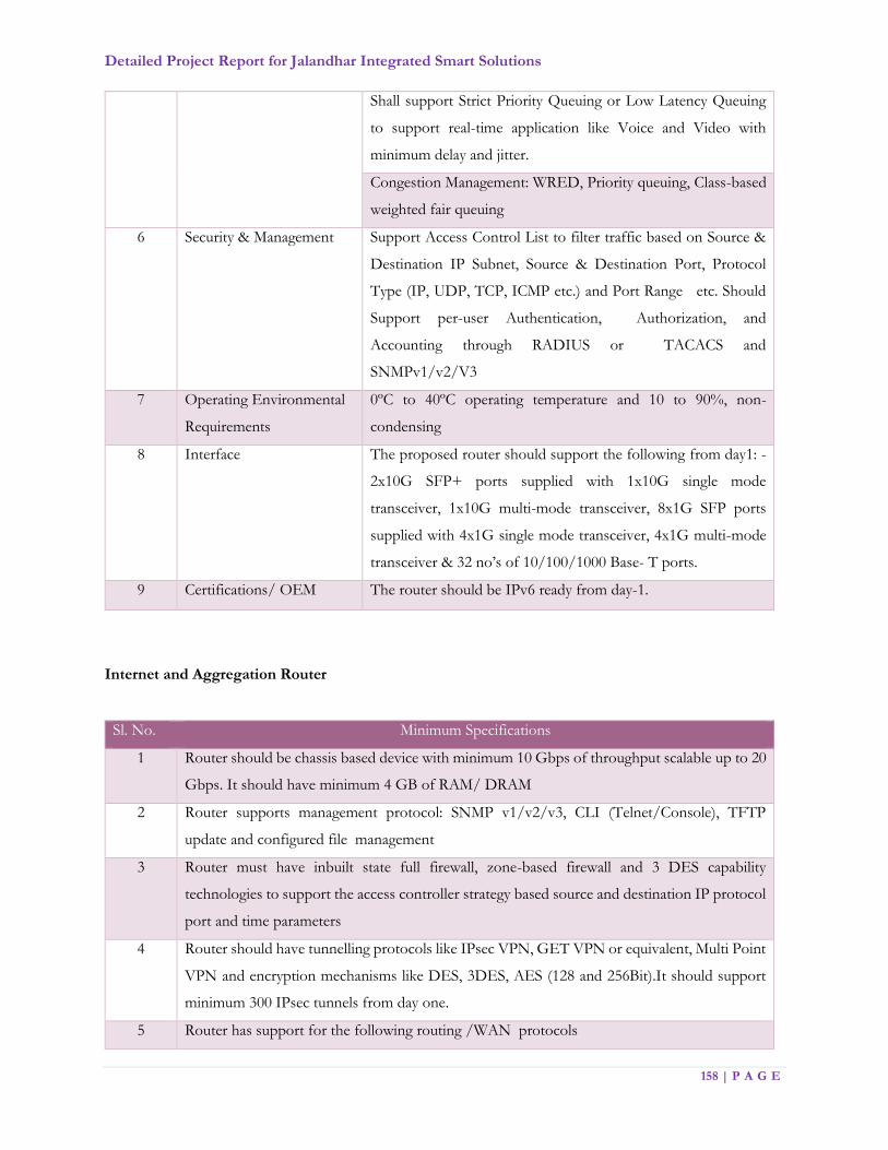
Detailed Project Report for Jalandhar Integrated Smart Solutions
158 | P A G E
Shall support Strict Priority Queuing or Low Latency Queuing
to support real-time application like Voice and Video with
minimum delay and jitter.
Congestion Management: WRED, Priority queuing, Class-based
weighted fair queuing
6 Security & Management Support Access Control List to filter traffic based on Source &
Destination IP Subnet, Source & Destination Port, Protocol
Type (IP, UDP, TCP, ICMP etc.) and Port Range etc. Should
Support per-user Authentication, Authorization, and
Accounting through RADIUS or TACACS and
SNMPv1/v2/V3
7 Operating Environmental
Requirements
0ºC to 40ºC operating temperature and 10 to 90%, non-
condensing
8 Interface The proposed router should support the following from day1: -
2x10G SFP+ ports supplied with 1x10G single mode
transceiver, 1x10G multi-mode transceiver, 8x1G SFP ports
supplied with 4x1G single mode transceiver, 4x1G multi-mode
transceiver & 32 no’s of 10/100/1000 Base- T ports.
9 Certifications/ OEM The router should be IPv6 ready from day-1.
Internet and Aggregation Router
Sl. No. Minimum Specifications
1 Router should be chassis based device with minimum 10 Gbps of throughput scalable up to 20
Gbps. It should have minimum 4 GB of RAM/ DRAM
2 Router supports management protocol: SNMP v1/v2/v3, CLI (Telnet/Console), TFTP
update and configured file management
3 Router must have inbuilt state full firewall, zone-based firewall and 3 DES capability
technologies to support the access controller strategy based source and destination IP protocol
port and time parameters
4 Router should have tunnelling protocols like IPsec VPN, GET VPN or equivalent, Multi Point
VPN and encryption mechanisms like DES, 3DES, AES (128 and 256Bit).It should support
minimum 300 IPsec tunnels from day one.
5 Router has support for the following routing /WAN protocols

Detailed Project Report for Jalandhar Integrated Smart Solutions
159 | P A G E
6 PPP/MLPPP, HDLC
7 Router should be modular chassis based device and should accommodate a combination of
high-density 10G, Gigabit Ethernet, Fast Ethernet
8 Router should support protocols like RIP, OSPF, BGP, VRRP/HSRP, 802.1q, GRE, ACL's
and NAT MPLS, traffic engineering, EoMPLS or VPLS
9 or equivalent, L2 VPN from day one
10 Shall support the RIPng & BGP for IPv6, OSPFv3, MPLS, BGP from day one.
11 The router supports state full packet inspection supporting H.323, SIP and other application
level gateway support
12 The state full firewall supports IPsec pass through
13 System shall support to provide the ability to filter and gather application information in a
flexible manner from day one
14 Router should support QoS Classification and marking policy based routing, IP precedence,
DSCP
15 QoS -congestion management WRED/RED, Priority queuing, class-based weighted for fair
queuing
16 IP Access list to limit Telnet SNMP access to router
17 Multiple privilege level authentication for console and telnet access
18 Time-based ACL for controlled forwarding based on time of day for offices
19 Should have extensive support for SLA monitoring for metrics like delay latency, jitter, packet
loss and MoS
20 Provides QoS features like traffic prioritization, differentiated services, and committed, and
committed access rate, QoS Support, RSVP/WFQ/MRED. Router should be able to take pre-
configured action on these events like changing routes, changing routing metric
21 Router supports for QoS Features for defining the QoS policies. Support for low latency
queuing, Layer 2 and Layer 3 CoS/DSCP
22 Router should have multicast routing protocols support: IGMPv1, v2 (RFC2236) PIM-SM
(RFC2362) and PIM-DM/ Multicast VLAN Registration
23 The following interface required from Day-1: 2x 10G SFP+ based ports loaded with single
mode transceiver, 3*1GE & 3*1G SFP-based transceiver.
24 The router should be IPv6 ready

Detailed Project Report for Jalandhar Integrated Smart Solutions
160 | P A G E
Layer 3 Switch
Sl. No. Parameter Minimum Specifications
1 Switch type Layer 3
2 Ports 24 or 48 (as per requirements) 10/100/1000 Base-T/TX/FX ports All ports can auto-negotiate between 10Mbps/ 100Mbps/ 1000Mbps,
half-duplex or full duplex and flow control for half duplex ports
100Mbps/1000Mbps, half duplex or full duplex and flow control for half
duplex ports
3 MAC Support 60 K MAC address
4 Backplane Properly sized Switching fabric capacity (as per network configuration to
meet performance requirements of wire speed switching for the
connected devices)
5 Forwarding rate 100 Mbps or higher for both IPv4 and IPv6
6 Port Features Must support Port Mirroring, Port Trunking and 802.3ad LACP Link
Aggregation port trunks
7 Flow Control Support IEEE 802.3x flow control for full-duplex mode ports
8 Protocols Should Support IP routing, RIP, OSPF, PIM
Should support IGMP snooping v1,v2 & v3
Should support Secure Shell (SSH) Protocol and Simple
Network Management Protocol
9 Access Control Support 802.1x (Port based network access control).
Support for MAC filtering.
Should support RADIUS authentication
10 VLAN Support 802.1 Q Tagged VLAN and port based VLANs and
Private VLAN
The switch must support dynamic VLAN Registration or
equivalent Dynamic Trunking protocol or equivalent
11 Traffic Switch should support traffic segmentation
Traffic classification should be based on user-definable
application types: TOS, DSCP, Port based, TCP/UDP port
number
12 Management Switch needs to have RS-232 or any other console port for
management via a console terminal or PC
Must have support SNMP v1, v2 and v3

Detailed Project Report for Jalandhar Integrated Smart Solutions
161 | P A G E
Should support 4 groups of RMON
Should have accessibility using Telnet, SSH, Console access,
easier software upgrade through network using TFTP etc.
Configuration management through CLI, GUI based software
utility and using web interface
Switch should be manageable through both IPv4 & IPv6
Should have modular OS and should support configuration roll back to
recover mis-configured switch to last known good configuration
13 Power Supplies Redundant power supply
Layer 2 Switch
Sl. No. Parameter Minimum Specifications
1 Switch type Layer 2
2 Ports 24 or 48 (as per requirements) 10/100/1000 Base-T Ethernet Port
3 MAC Support 8K or more MAC address
4 Backplane Properly sized Switching fabric capacity (as per network configuration
to meet performance requirements of wire speed switching for the
connected devices)
5 Forwarding rate Packet Forwarding Rate should be 70.0 Mbps or better
6 Port Features Must support Port Mirroring, Port Trunking and 802.3ad LACP Link
Aggregation port trunks
7 Transfer Rate Non-Blocking, Wire speed Architecture
8 Flow Control Support IEEE 802.3x flow control for full-duplex mode ports
9 Protocols IPV4, IPv6
Support 802.1D, 802.1S, 802.1w, Rate limiting
Support 802.1Q VLAN encapsulation, IGMP v1, v2 and v3
snooping
802.1p Priority Queues, port mirroring, DiffServ
DHCP support
Support up to 1024 VLAN

Detailed Project Report for Jalandhar Integrated Smart Solutions
162 | P A G E
10 Access Control Support port security
Support 802.1x (Port based network access control).
Support for MAC filtering.
Should support TACACS+ and RADIUS authentication
11 VLAN Support 802.1Q Tagged VLAN and port based VLANs and Private
VLAN. The switch must support dynamic VLAN Registration or
equivalent Dynamic Trunking protocol or equivalent
12 Protocol and
Traffic
Network Time Protocol or equivalent Simple Network Time Protocol
support switch should support traffic segmentation. Traffic classification
should be based on user-definable application types: TOS, DSCP, Port
based, TCP/UDP port number
13 Management Switch needs to have RS-232or any other console port for management
via a console terminal or PC. Must have support SNMP v1, v2 and v3.
Should support 4 groups of RMON. Should have accessibility using
Telnet, SSH, Console access, easier software upgrade through network
using TFTP etc. Configuration management through CLI, GUI based
software utility and using web interface
SAN Storage
Sl. No. Parameter Minimum Specifications
1 RAID Level RAID Array supporting Raid Levels 0, 1, 5,0+1 / 10 or equivalent
2 Availability
and
Required
Cache
Cache should be mirrored between Active-Active controllers on dedicated,
redundant paths / links between the controllers. In case of power failure, the
SAN array must be provided with cache protection mechanism to ensure no
loss of data in cache by de- staging to disks, irrespective of duration of power
outage. The Proposed SAN Array should be configured with at least 16 GB
usable data cache or higher or as per proposed solution for storage
3 Reliability The proposed SAN Array should be configured with No Single Point of Failure
Architecture with Dual Controllers for redundancy and should support hot plug
and hot swap of components online (including controllers, disks, power
supplies, cooling fans etc.). Should have continuous system monitoring and
shall support remote diagnostics / error reporting feature. It should also allow
the recovery of data in transit in the event of failure
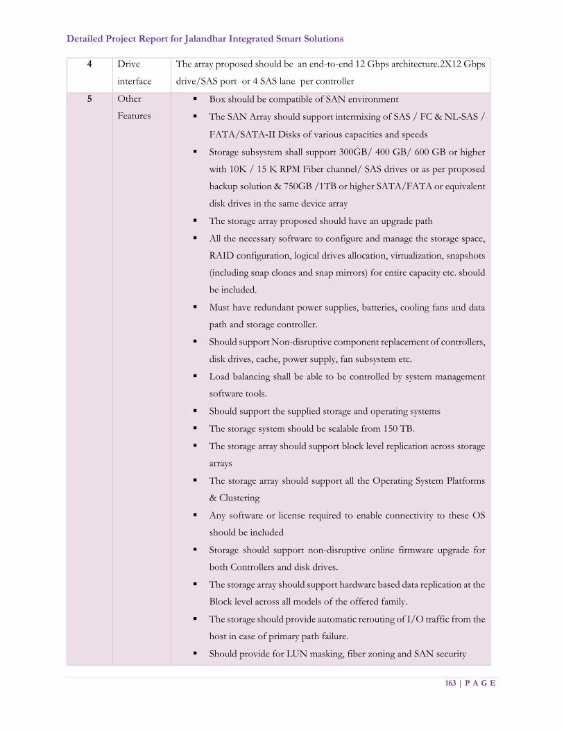
Detailed Project Report for Jalandhar Integrated Smart Solutions
163 | P A G E
4 Drive
interface
The array proposed should be an end-to-end 12 Gbps architecture.2X12 Gbps
drive/SAS port or 4 SAS lane per controller
5 Other
Features
Box should be compatible of SAN environment
The SAN Array should support intermixing of SAS / FC & NL-SAS /
FATA/SATA‐II Disks of various capacities and speeds
Storage subsystem shall support 300GB/ 400 GB/ 600 GB or higher
with 10K / 15 K RPM Fiber channel/ SAS drives or as per proposed
backup solution & 750GB /1TB or higher SATA/FATA or equivalent
disk drives in the same device array
The storage array proposed should have an upgrade path
All the necessary software to configure and manage the storage space,
RAID configuration, logical drives allocation, virtualization, snapshots
(including snap clones and snap mirrors) for entire capacity etc. should
be included.
Must have redundant power supplies, batteries, cooling fans and data
path and storage controller.
Should support Non-disruptive component replacement of controllers,
disk drives, cache, power supply, fan subsystem etc.
Load balancing shall be able to be controlled by system management
software tools.
Should support the supplied storage and operating systems
The storage system should be scalable from 150 TB.
The storage array should support block level replication across storage
arrays
The storage array should support all the Operating System Platforms
& Clustering
Any software or license required to enable connectivity to these OS
should be included
Storage should support non-disruptive online firmware upgrade for
both Controllers and disk drives.
The storage array should support hardware based data replication at the
Block level across all models of the offered family.
The storage should provide automatic rerouting of I/O traffic from the
host in case of primary path failure.
Should provide for LUN masking, fiber zoning and SAN security

Detailed Project Report for Jalandhar Integrated Smart Solutions
164 | P A G E
Should support storage virtualization, i.e. Easy logical drive expansion.
Storage should be supplied with virtualization license as per solution
requirement
Should support hot-swappable physical drive raid array expansion with
the addition of extra hard disks
Should be able to support clustered and individual servers at the same
time.
Should be able to take "snapshots" of the stored data to another logical
drive on a different Disk/RAID Group for backup purposes
Should be configured with "snapshots and clone"
The vendor must provide the functionality of proactive monitoring of
Disk drive and Storage system for all possible hard or soft disk failure.
Vendor should also offer storage performance monitoring and
management software.
The storage system shall be configured with GUI based management
software as below:
Monitor and manage the storage array Configuration
Remote Storage base replication
Storage front end port monitoring
Disk Monitoring
LUN management.
Storage Component replacement, etc.
6 Note All specifications stated are minimum required. Proposed system may have
features over and above the minimum specification stated. Bidder should ensure
that the performance of storage is not negatively affected
SAN Switch
Sl. No. Minimum Specifications
1 The fibre channel switch must be rack-mountable. Thereafter, all reference to the ‘switch’ shall
pertain to the ‘fibre channel switch’
2 The switch to be configured with minimum of 96 ports 16 Gbps FC configuration backward
compatible to 4/8
3 All 96 x FC ports for device connectivity should be 4/8/16 Gbps auto-sensing Fibre Channel
ports
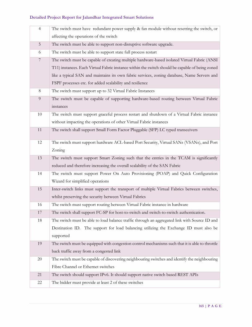
Detailed Project Report for Jalandhar Integrated Smart Solutions
165 | P A G E
4 The switch must have redundant power supply & fan module without resetting the switch, or
affecting the operations of the switch
5 The switch must be able to support non-disruptive software upgrade.
6 The switch must be able to support state full process restart
7 The switch must be capable of creating multiple hardware-based isolated Virtual Fabric (ANSI
T11) instances. Each Virtual Fabric instance within the switch should be capable of being zoned
like a typical SAN and maintains its own fabric services, zoning database, Name Servers and
FSPF processes etc. for added scalability and resilience
8 The switch must support up to 32 Virtual Fabric Instances
9 The switch must be capable of supporting hardware-based routing between Virtual Fabric
instances
10 The switch must support graceful process restart and shutdown of a Virtual Fabric instance
without impacting the operations of other Virtual Fabric instances
11 The switch shall support Small Form Factor Pluggable (SFP) LC typed transceivers
12 The switch must support hardware ACL-based Port Security, Virtual SANs (VSANs), and Port
Zoning
13 The switch must support Smart Zoning such that the entries in the TCAM is significantly
reduced and therefore increasing the overall scalability of the SAN Fabric
14 The switch must support Power On Auto Provisioning (POAP) and Quick Configuration
Wizard for simplified operations
15 Inter-switch links must support the transport of multiple Virtual Fabrics between switches,
whilst preserving the security between Virtual Fabrics
16 The switch must support routing between Virtual Fabric instance in hardware
17 The switch shall support FC-SP for host-to-switch and switch-to-switch authentication.
18 The switch must be able to load balance traffic through an aggregated link with Source ID and
Destination ID. The support for load balancing utilizing the Exchange ID must also be
supported
19 The switch must be equipped with congestion control mechanisms such that it is able to throttle
back traffic away from a congested link
20 The switch must be capable of discovering neighbouring switches and identify the neighbouring
Fibre Channel or Ethernet switches
21 The switch should support IPv6. It should support native switch based REST APIs
22 The bidder must provide at least 2 of these switches
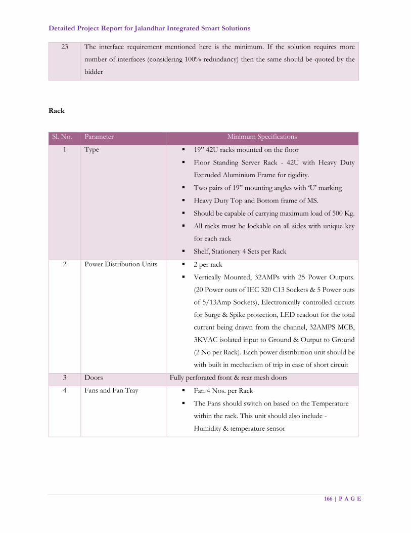
Detailed Project Report for Jalandhar Integrated Smart Solutions
166 | P A G E
23 The interface requirement mentioned here is the minimum. If the solution requires more
number of interfaces (considering 100% redundancy) then the same should be quoted by the
bidder
Rack
Sl. No. Parameter Minimum Specifications
1 Type 19” 42U racks mounted on the floor
Floor Standing Server Rack - 42U with Heavy Duty
Extruded Aluminium Frame for rigidity.
Two pairs of 19” mounting angles with ‘U’ marking
Heavy Duty Top and Bottom frame of MS.
Should be capable of carrying maximum load of 500 Kg.
All racks must be lockable on all sides with unique key
for each rack
Shelf, Stationery 4 Sets per Rack
2 Power Distribution Units 2 per rack
Vertically Mounted, 32AMPs with 25 Power Outputs.
(20 Power outs of IEC 320 C13 Sockets & 5 Power outs
of 5/13Amp Sockets), Electronically controlled circuits
for Surge & Spike protection, LED readout for the total
current being drawn from the channel, 32AMPS MCB,
3KVAC isolated input to Ground & Output to Ground
(2 No per Rack). Each power distribution unit should be
with built in mechanism of trip in case of short circuit
3 Doors Fully perforated front & rear mesh doors
4 Fans and Fan Tray Fan 4 Nos. per Rack
The Fans should switch on based on the Temperature
within the rack. This unit should also include -
Humidity & temperature sensor

Detailed Project Report for Jalandhar Integrated Smart Solutions
167 | P A G E
Rack Server
Sl. No. Parameter Minimum Specifications
1 Chipset Lewisburg PCH Intel C621 or equivalent or higher
2 Form Factor Max. 2U rack mounted with sliding rails
3 CPU Latest series/ generation of 64 bit x86 processors E5- 2640V4 -with
Ten or higher Cores. Processor speed should be minimum 2.4 GHz. 2
processors per each physical server. Scalable up to up to 28 cores per
processor
4 Memory Slots 24 DDR4 DIMM slots RDIMMS& LR DIMMS supporting speeds up
to 2666MT/s. Optionally support up to 12 DIMM & 12 NVDIMM
5 Memory
configured
Minimum 128 GB RAM, scalable to 1.5TB
6 RAID Controller 12Gbps PCIe 3.0 with RAID 1, 5, 6,10, 50
7 Disks configured Minimum 8 x 2.5” SAS/SATA/SSD or 4 x 3.5” SAS/SATA
8 I/O slots Up to 8x PCIe Gen3 Slots
9 GPU Support Up to 3 DW and 6 SW GPU cards
10 Ethernet ports 4 x 1G RJ45 LOM
11 Certification and
compliances
Microsoft Windows Server, Hyper-V, VMWare, Red Hat Enterprise
Linux (RHEL), SUSE Linux Enterprise Server (SLES)
12 Power Supply Platinum rated redundant Power Supply
13 SD Modules slots Dual SD Module slots supporting redundant configuration
14 Management
integration
Support for integration with systems such as Microsoft System Center,
VMware vCenter, BMC Software et
15 Pre-failure alert Should provide predictive failure monitoring & proactive alerts of
actual or impending component failure
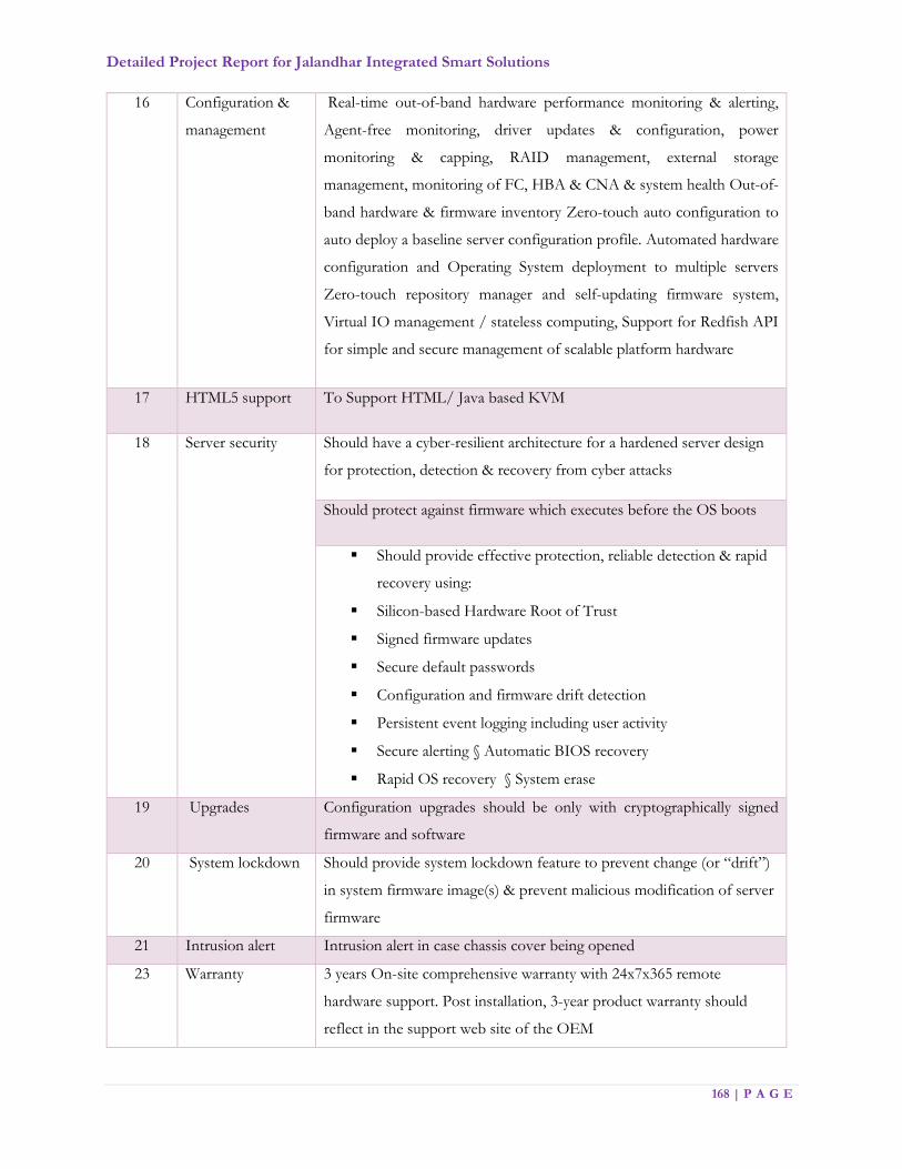
Detailed Project Report for Jalandhar Integrated Smart Solutions
168 | P A G E
16 Configuration &
management
Real-time out-of-band hardware performance monitoring & alerting,
Agent-free monitoring, driver updates & configuration, power
monitoring & capping, RAID management, external storage
management, monitoring of FC, HBA & CNA & system health Out-of-
band hardware & firmware inventory Zero-touch auto configuration to
auto deploy a baseline server configuration profile. Automated hardware
configuration and Operating System deployment to multiple servers
Zero-touch repository manager and self-updating firmware system,
Virtual IO management / stateless computing, Support for Redfish API
for simple and secure management of scalable platform hardware
17 HTML5 support To Support HTML/ Java based KVM
18
Server security
Should have a cyber-resilient architecture for a hardened server design
for protection, detection & recovery from cyber attacks
Should protect against firmware which executes before the OS boots
Should provide effective protection, reliable detection & rapid
recovery using:
Silicon-based Hardware Root of Trust
Signed firmware updates
Secure default passwords
Configuration and firmware drift detection
Persistent event logging including user activity
Secure alerting § Automatic BIOS recovery
Rapid OS recovery § System erase
19 Upgrades Configuration upgrades should be only with cryptographically signed
firmware and software
20 System lockdown Should provide system lockdown feature to prevent change (or “drift”)
in system firmware image(s) & prevent malicious modification of server
firmware
21 Intrusion alert Intrusion alert in case chassis cover being opened
23 Warranty 3 years On-site comprehensive warranty with 24x7x365 remote
hardware support. Post installation, 3-year product warranty should
reflect in the support web site of the OEM

Detailed Project Report for Jalandhar Integrated Smart Solutions
169 | P A G E
KVM Switch
Sl. No. Parameter Minimum Specifications
1 KVM Requirement Keyboard, Video Display Unit and Mouse Unit (KVM) for the
IT Infrastructure Management at Data Center
2 Form Factor 19” rack mountable
3 Ports Minimum 8 ports
4 Server Connections USB or KVM over IP
5 Auto-Scan It should be capable to auto scan servers
6 Rack Access It should support local user port for rack access
7 SNMP The KVM switch should be SNMP enabled. It should be
operable from remote locations
8 OS Support It should support multiple operating system
9 Power Supply It should have dual power with failover and built-in surge
protection
10 Multi-User support It should support multi-user access and collaboration
11 Power Specification 200-240V, 50-60 Hz
12 Operating temperature
range
0° to 45° C
13 Operating Relative
Humidity range (non-
condensing)
10 to 90% relative humidity
14 Total no. of ports on the
proposed switch
24
15 Throughput of each FC
port
8/16Gbps
16 Support for 4/8/16 Gb/s
HBAs
YES
17 Interface Support for 4/8/16 Gb/s HBAs
18 Security RADIUS, SSH, SNMP
19 Availability No single point of failure
Redundant Power supply
Backup Appliance
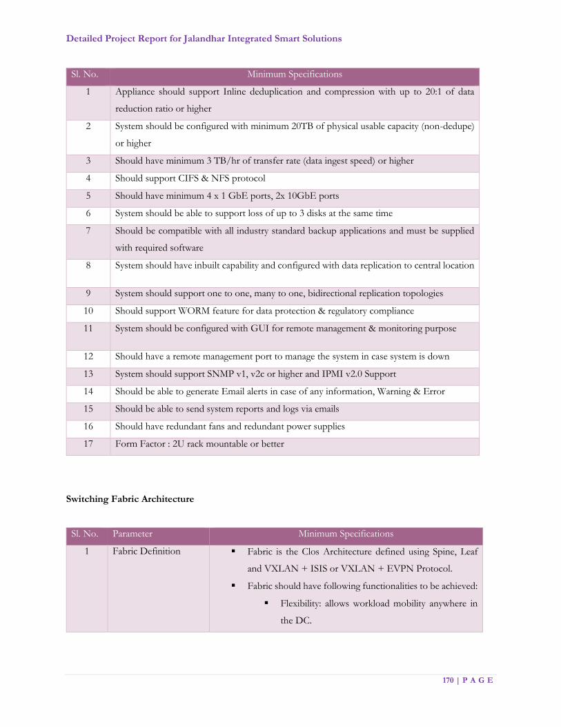
Detailed Project Report for Jalandhar Integrated Smart Solutions
170 | P A G E
Sl. No. Minimum Specifications
1 Appliance should support Inline deduplication and compression with up to 20:1 of data
reduction ratio or higher
2 System should be configured with minimum 20TB of physical usable capacity (non-dedupe)
or higher
3 Should have minimum 3 TB/hr of transfer rate (data ingest speed) or higher
4 Should support CIFS & NFS protocol
5 Should have minimum 4 x 1 GbE ports, 2x 10GbE ports
6 System should be able to support loss of up to 3 disks at the same time
7 Should be compatible with all industry standard backup applications and must be supplied
with required software
8 System should have inbuilt capability and configured with data replication to central location
9 System should support one to one, many to one, bidirectional replication topologies
10 Should support WORM feature for data protection & regulatory compliance
11 System should be configured with GUI for remote management & monitoring purpose
12 Should have a remote management port to manage the system in case system is down
13 System should support SNMP v1, v2c or higher and IPMI v2.0 Support
14 Should be able to generate Email alerts in case of any information, Warning & Error
15 Should be able to send system reports and logs via emails
16 Should have redundant fans and redundant power supplies
17 Form Factor : 2U rack mountable or better
Switching Fabric Architecture
Sl. No. Parameter Minimum Specifications
1 Fabric Definition Fabric is the Clos Architecture defined using Spine, Leaf
and VXLAN + ISIS or VXLAN + EVPN Protocol.
Fabric should have following functionalities to be achieved:
Flexibility: allows workload mobility anywhere in
the DC.
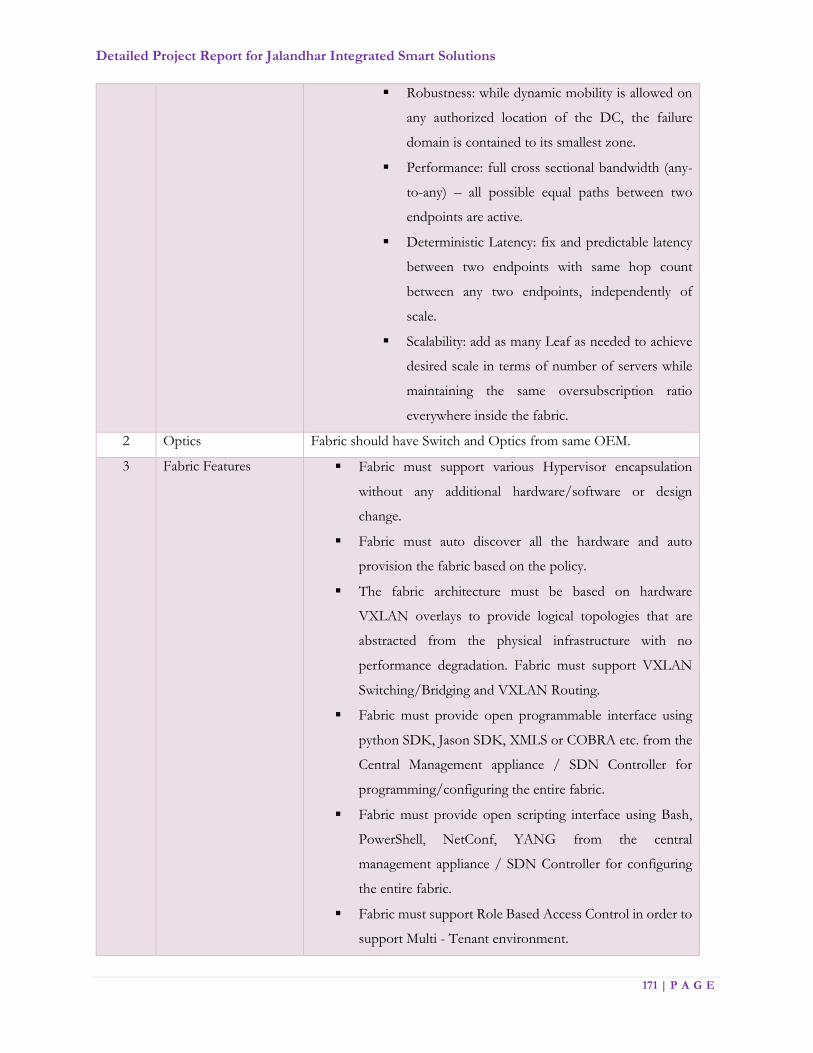
Detailed Project Report for Jalandhar Integrated Smart Solutions
171 | P A G E
Robustness: while dynamic mobility is allowed on
any authorized location of the DC, the failure
domain is contained to its smallest zone.
Performance: full cross sectional bandwidth (any-
to-any) – all possible equal paths between two
endpoints are active.
Deterministic Latency: fix and predictable latency
between two endpoints with same hop count
between any two endpoints, independently of
scale.
Scalability: add as many Leaf as needed to achieve
desired scale in terms of number of servers while
maintaining the same oversubscription ratio
everywhere inside the fabric.
2 Optics Fabric should have Switch and Optics from same OEM.
3 Fabric Features Fabric must support various Hypervisor encapsulation
without any additional hardware/software or design
change.
Fabric must auto discover all the hardware and auto
provision the fabric based on the policy.
The fabric architecture must be based on hardware
VXLAN overlays to provide logical topologies that are
abstracted from the physical infrastructure with no
performance degradation. Fabric must support VXLAN
Switching/Bridging and VXLAN Routing.
Fabric must provide open programmable interface using
python SDK, Jason SDK, XMLS or COBRA etc. from the
Central Management appliance / SDN Controller for
programming/configuring the entire fabric.
Fabric must provide open scripting interface using Bash,
PowerShell, NetConf, YANG from the central
management appliance / SDN Controller for configuring
the entire fabric.
Fabric must support Role Based Access Control in order to
support Multi - Tenant environment.

Detailed Project Report for Jalandhar Integrated Smart Solutions
172 | P A G E
Fabric must integrate with different virtual machine
manager and manage virtualise networking from the single
pane of Glass - Fabric Controller/SDN Controller.
Fabric must integrate with best of breed L4 - L7 Physical
and virtual appliances and manage using single pane of glass
- Fabric Controller / SDN Controller.
Fabric must provide deeper visibility into the fabric in terms
of latency and packet drop between VM to VM, VM to
Physical server and vice versa, Leaf to another leaf etc.
Fabric must act as single distributed layer 2 switch, Layer 3
router and Stateless distributed firewall etc.
Fabric must provide REST APIs from the Central
management appliance/SDN Controller in order to
integrate with best of breed Management, Monitoring,
Hypervisor and Cloud automation & Orchestration
software.
4 Fabric Layer 2, Layer 3
and Misc. Features
Fabric must support Layer 2 features like LACP, STP
/RSTP /MSTP, VLAN Trunking, LLDP etc.
Fabric must support multi chassis ether channel/MLAG i.e.
Host connects to two different Leaf switches and form
ether channel using LACP/NIC Teaming on Host.
Fabric must support Jumbo Frame up to 9K Bytes on
1G/10G/25G/40G/100G ports.
Fabric must support Layer 2 Multicast i.e. IGMP v1, v2 and
v3.
Fabric must support IP v4 and IP v6 FHRP using HSRP or
VRRP.
Fabric must support IP v4 and IP v6 Layer 3 routing
protocol OSPF and BGP.
Fabric must support IP v6 dual stack.
Fabric must support traffic redistribution between different
routing protocols.
Fabric must support IP v4 and IP v6 management tools like
- Ping, Traceroute, VTY, SSH, TFTP and DNS Lookup.
Fabric must support IP v4 and IP v6 SNMP V1 / V2 / V3.

Detailed Project Report for Jalandhar Integrated Smart Solutions
173 | P A G E
Fabric must support RMON/RMON-II for monitoring.
Fabric must support integration with the centralised Syslog
server for monitoring and audit trail.
Fabric must support NTP.
5 Fabric Security
Features
Fabric must have zero trust policy model for connected
systems or hosts to help in protecting against any kind of
attacks like Unauthorized Access, Man - in - the - middle -
attack, Replay Attack, Data Disclosure, Denial of Service.
Fabric must provide RBAC policies and support AAA using
Local User authentication, External RADIUS, External
TACACS+, External LDAP, External AD.
Fabric must support VM attribute based zoning and policy.
Fabric must support Micro Segmentation for the Virtualize
and Non - Virtualize environment.
Fabric must support true multi tenancy.
Fabric must be accessible using CLI over SSH and GUI
using HTTP/HTTPS
Fabric must support SNMP v2/3 with HMAC-MD5 or
HMAC-SHA authentication and DES encryption.
Fabric must act as a State-less distributed firewall with the
logging capability.
6 Fabric Service Features Fabric must be capable to provide services of L 4 - L7
services using physical or virtual appliances i.e. Firewall,
ADC, IPS etc.
Fabric must have zero trust policy model for connected
systems or hosts to help in protecting against any kind of
attacks like Unauthorized Access, Man - in - the - middle -
attack, Replay Attack, Data Disclosure, Denial of Service.
7 Fabric Scale and
Performance
Fabric should support scale up and scale out without any
service disruption.
Fabric must support for 500 VRF/Private network without
any additional component or upgrade or design change.
Fabric must scale from 100 Tenant to 500 Tenant without
any additional component or upgrade or design change.

Detailed Project Report for Jalandhar Integrated Smart Solutions
174 | P A G E
Fabric must integrate with minimum 3 Virtual Machine
Manager (i.e. vCenter, SCVMM, OpenStack etc.) of
different Hypervisors simultaneously and scalable to 5 in
future with or without common orchestrator.
Fabric must be capable of connecting 2500 physical servers
and scale to 5000 physical servers.
Fabric must be capable of integrating minimum of 8 nos. of
L 4 - L7 services physical or virtual appliances (i.e. Firewall,
ADC, IPS etc.) and scale up to 16 no’s of L4 - L7 Services
appliances.
Fabric must support minimum of 4 Leaf switches and scale
up to 250 Leaf switches without any design change.
Fabric must support minimum of 2 Spine Switches and
scale up to 6 Spine switches without any design change.
Spine Switches must have adequate number of line rate
40/100G ports to support desired Leaf Scale.
Each Leaf connects to Each Spine using minimum 1 x
40/100 G ports connectivity i.e. Each Spine must have 128
nos. of line rate 40G/100G ports with consideration of leaf
to SPINE over subscription ration of 4:1.
Fabric must support 20K IPv4 and 10K IPv6 routes
scalable to 30K IPv4 and 15K IPv6 routes.
Fabric must support 4K multicast groups scalable to 8K
multicast groups.
Fabric must support 256 nos. of MLAG/VPC scalable to
384 nos. Each MLAG/VPC must support maximum 8-
member links.
Fabric must support 256 nos. of Port Channel scalable to
384 nos. Each Port Channel must support maximum of 8
member links.
8 Fabric Management Fabric must provide Centralised Management Appliance or
SDN Controller - Single pane of Glass for managing,
monitoring and provisioning the entire Fabric.
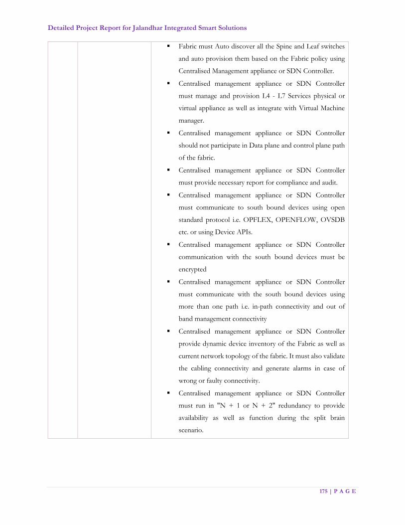
Detailed Project Report for Jalandhar Integrated Smart Solutions
175 | P A G E
Fabric must Auto discover all the Spine and Leaf switches
and auto provision them based on the Fabric policy using
Centralised Management appliance or SDN Controller.
Centralised management appliance or SDN Controller
must manage and provision L4 - L7 Services physical or
virtual appliance as well as integrate with Virtual Machine
manager.
Centralised management appliance or SDN Controller
should not participate in Data plane and control plane path
of the fabric.
Centralised management appliance or SDN Controller
must provide necessary report for compliance and audit.
Centralised management appliance or SDN Controller
must communicate to south bound devices using open
standard protocol i.e. OPFLEX, OPENFLOW, OVSDB
etc. or using Device APIs.
Centralised management appliance or SDN Controller
communication with the south bound devices must be
encrypted
Centralised management appliance or SDN Controller
must communicate with the south bound devices using
more than one path i.e. in-path connectivity and out of
band management connectivity
Centralised management appliance or SDN Controller
provide dynamic device inventory of the Fabric as well as
current network topology of the fabric. It must also validate
the cabling connectivity and generate alarms in case of
wrong or faulty connectivity.
Centralised management appliance or SDN Controller
must run in "N + 1 or N + 2" redundancy to provide
availability as well as function during the split brain
scenario.
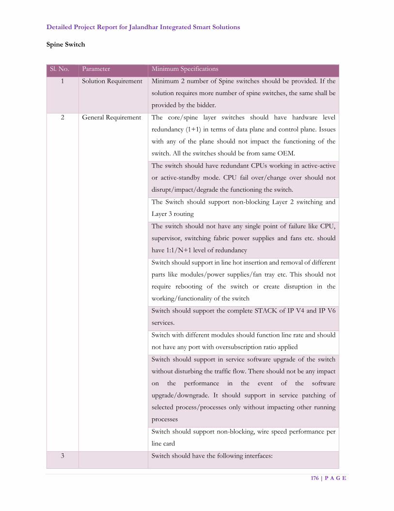
Detailed Project Report for Jalandhar Integrated Smart Solutions
176 | P A G E
Spine Switch
Sl. No. Parameter Minimum Specifications
1 Solution Requirement Minimum 2 number of Spine switches should be provided. If the
solution requires more number of spine switches, the same shall be
provided by the bidder.
2 General Requirement The core/spine layer switches should have hardware level
redundancy (1+1) in terms of data plane and control plane. Issues
with any of the plane should not impact the functioning of the
switch. All the switches should be from same OEM.
The switch should have redundant CPUs working in active-active
or active-standby mode. CPU fail over/change over should not
disrupt/impact/degrade the functioning the switch.
The Switch should support non-blocking Layer 2 switching and
Layer 3 routing
The switch should not have any single point of failure like CPU,
supervisor, switching fabric power supplies and fans etc. should
have 1:1/N+1 level of redundancy
Switch should support in line hot insertion and removal of different
parts like modules/power supplies/fan tray etc. This should not
require rebooting of the switch or create disruption in the
working/functionality of the switch
Switch should support the complete STACK of IP V4 and IP V6
services.
Switch with different modules should function line rate and should
not have any port with oversubscription ratio applied
Switch should support in service software upgrade of the switch
without disturbing the traffic flow. There should not be any impact
on the performance in the event of the software
upgrade/downgrade. It should support in service patching of
selected process/processes only without impacting other running
processes
Switch should support non-blocking, wire speed performance per
line card
3 Switch should have the following interfaces:

Detailed Project Report for Jalandhar Integrated Smart Solutions
177 | P A G E
Hardware and
Interface Requirement
36 nos. of line rate and Non - Blocking 40/100G ports
Switch should have min 80MB buffer
Switch should have EAL2/NDPP certified
Switch should have console port for local management
Switch should have management interface for Out of Band
Management
Switch should be rack mountable and support side rails, if required
Switch should have adequate power supplies for the complete
system usage with all slots populated and used, providing N+1
redundancy
Switch should have hardware health monitoring capabilities and
should provide different parameters through SNMP
Switch should support VLAN tagging (IEEE 802.1q)
Switch should support IEEE Link Aggregation and Ethernet
Bonding functionality to group multiple ports for redundancy
Switch should have the capability of holding multiple OS images to
support resilience & easy rollbacks during the version upgrades etc
and should support in service software upgrade including:
Multiple System image
Multiple system configuration
Option of Configuration roll-back
Switch should support for different logical interface types like
loopback, VLAN, SVI, Port Channel, multi chassis port
channel/Link Aggregation Group (LAG) etc.
4 Performance
Requirement
The switch should support 1,20,000 IPv4 and IPv6 routes entries in
the routing table with multicast routes
Switch should support Graceful Restart for OSPF, BGP etc.
Switch should support minimum 1000 VRF instances
The switch should support uninterrupted forwarding operation for
OSPF, BGP etc. routing protocol to ensure high-availability during
primary controller failure
The switch should support hardware based load-balancing at wire
speed using LACP and multi chassis ether channel/LAG
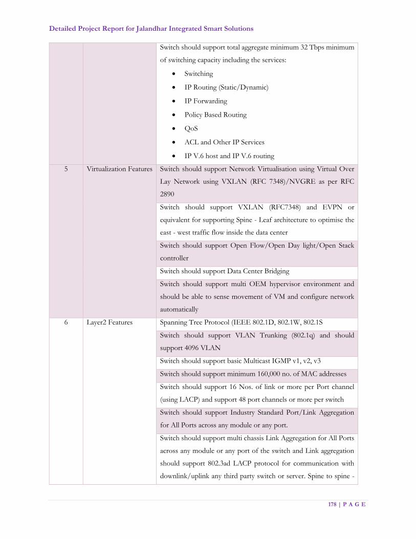
Detailed Project Report for Jalandhar Integrated Smart Solutions
178 | P A G E
Switch should support total aggregate minimum 32 Tbps minimum
of switching capacity including the services:
Switching
IP Routing (Static/Dynamic)
IP Forwarding
Policy Based Routing
QoS
ACL and Other IP Services
IP V.6 host and IP V.6 routing
5 Virtualization Features Switch should support Network Virtualisation using Virtual Over
Lay Network using VXLAN (RFC 7348)/NVGRE as per RFC
2890
Switch should support VXLAN (RFC7348) and EVPN or
equivalent for supporting Spine - Leaf architecture to optimise the
east - west traffic flow inside the data center
Switch should support Open Flow/Open Day light/Open Stack
controller
Switch should support Data Center Bridging
Switch should support multi OEM hypervisor environment and
should be able to sense movement of VM and configure network
automatically
6 Layer2 Features Spanning Tree Protocol (IEEE 802.1D, 802.1W, 802.1S
Switch should support VLAN Trunking (802.1q) and should
support 4096 VLAN
Switch should support basic Multicast IGMP v1, v2, v3
Switch should support minimum 160,000 no. of MAC addresses
Switch should support 16 Nos. of link or more per Port channel
(using LACP) and support 48 port channels or more per switch
Switch should support Industry Standard Port/Link Aggregation
for All Ports across any module or any port.
Switch should support multi chassis Link Aggregation for All Ports
across any module or any port of the switch and Link aggregation
should support 802.3ad LACP protocol for communication with
downlink/uplink any third party switch or server. Spine to spine -

Detailed Project Report for Jalandhar Integrated Smart Solutions
179 | P A G E
minimum 16 port Multi Chassis ether channel/LAG should be
provided.
Switch should support Jumbo Frames up to 9K Bytes on 1G/10G
Ports
Support for broadcast, multicast and unknown unicast storm
control to prevent degradation of switch performance from storm
due to network attacks and vulnerabilities
Switch should support Link Layer Discovery Protocol as per IEEE
802.1AB for finding media level failures
7 Layer3 Features Switch should support all physical ports to use either in Layer2 or
Layer 3 mode and also should support layer 3 VLAN Interface and
Loopback port Interface
Switch should support basic routing feature i.e. IP Classless, default
routing and Inter VLAN routing
Switch should support static and dynamic routing using:
Static routing
OSPF V.2 using MD5 Authentication
ISIS using MD5 Authentication
BGP V.4 using MD5 Authentication
Should support route redistribution between these
protocols
Should be compliant to RFC 4760 Multiprotocol
Extensions for BGP-4 (Desirable)
Switch should re-converge all dynamic routing protocol at the time
of routing update changes i.e. Non-Stop forwarding for fast re-
convergence of routing protocols
Switch should support multi instance MPLS routing using VRF,
VRF Edge routing and should support VRF Route leaking
functionality
Switch should be capable to work as DHCP server and relay
Switch should provide multicast traffic reachable using:
PIM-SM
PIM-SSM
Bi-Directional PIM

Detailed Project Report for Jalandhar Integrated Smart Solutions
180 | P A G E
Support RFC 3618 Multicast Source Discovery Protocol
(MSDP)
IGMP V.1, V.2 and V.3
Switch should support Multicast routing ECMP
8 Availability Switch should have provisioning for connecting to 1:1/N+1 power
supply for usage and redundancy
Switch should provide gateway level of redundancy in Ip V.4 and
IP V.6 using HSRP/VRRP
Switch should support for BFD For Fast Failure Detection as per
RFC 5880 and RFC-7419, 3618, 7296, 7427, 7296.
9 Quality of Service Switch system should support 802.1P classification and marking of
packet using:
CoS (Class of Service)
DSCP (Differentiated Services Code Point)
Source physical interfaces
Source/destination IP subnet
Protocol types (IP/TCP/UDP)
Source/destination TCP/UDP ports
Switch should support methods for identifying different types of
traffic for better management and resilience
Switch should support for different type of QoS features for ream
time traffic differential treatment using:
Weighted Random Early Detection
Strict Priority Queuing
Switch should support to trust the QoS marking/priority settings of
the end points as per the defined policy
Switch should support Flow control of Ethernet ports to control
traffic rates during congestion by allowing congested nodes to pause
link operation at the other end for receiving traffic as per IEEE
802.3x
10 Security Switch should support for deploying different security for each
logical and physical interface using Port Based access control lists
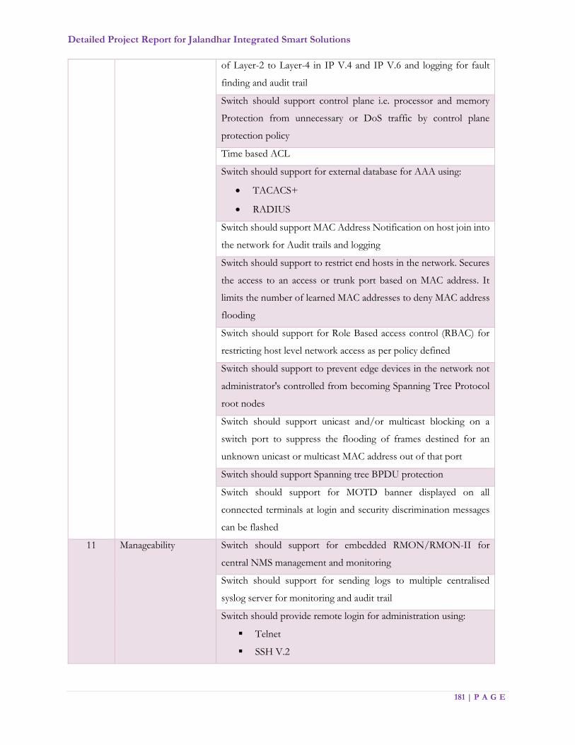
Detailed Project Report for Jalandhar Integrated Smart Solutions
181 | P A G E
of Layer-2 to Layer-4 in IP V.4 and IP V.6 and logging for fault
finding and audit trail
Switch should support control plane i.e. processor and memory
Protection from unnecessary or DoS traffic by control plane
protection policy
Time based ACL
Switch should support for external database for AAA using:
TACACS+
RADIUS
Switch should support MAC Address Notification on host join into
the network for Audit trails and logging
Switch should support to restrict end hosts in the network. Secures
the access to an access or trunk port based on MAC address. It
limits the number of learned MAC addresses to deny MAC address
flooding
Switch should support for Role Based access control (RBAC) for
restricting host level network access as per policy defined
Switch should support to prevent edge devices in the network not
administrator's controlled from becoming Spanning Tree Protocol
root nodes
Switch should support unicast and/or multicast blocking on a
switch port to suppress the flooding of frames destined for an
unknown unicast or multicast MAC address out of that port
Switch should support Spanning tree BPDU protection
Switch should support for MOTD banner displayed on all
connected terminals at login and security discrimination messages
can be flashed
11 Manageability Switch should support for embedded RMON/RMON-II for
central NMS management and monitoring
Switch should support for sending logs to multiple centralised
syslog server for monitoring and audit trail
Switch should provide remote login for administration using:
Telnet
SSH V.2
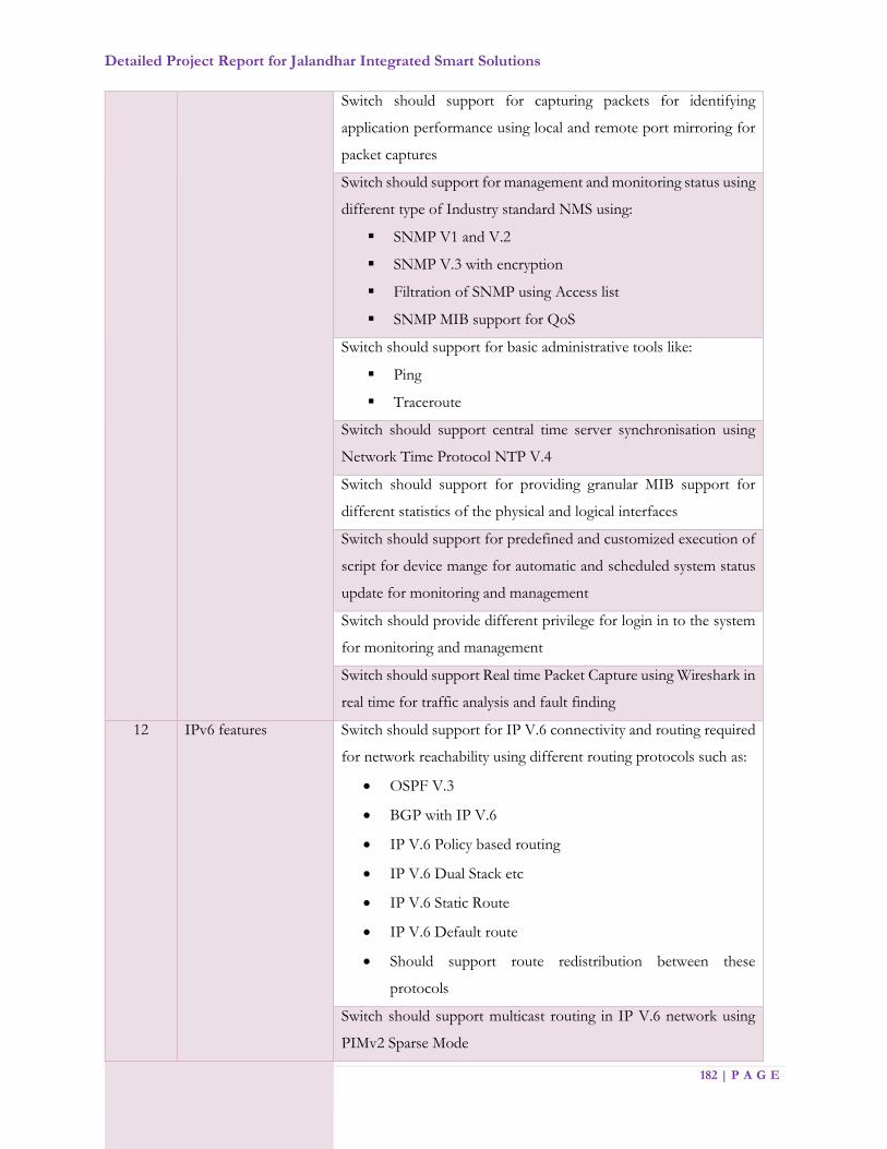
Detailed Project Report for Jalandhar Integrated Smart Solutions
182 | P A G E
Switch should support for capturing packets for identifying
application performance using local and remote port mirroring for
packet captures
Switch should support for management and monitoring status using
different type of Industry standard NMS using:
SNMP V1 and V.2
SNMP V.3 with encryption
Filtration of SNMP using Access list
SNMP MIB support for QoS
Switch should support for basic administrative tools like:
Ping
Traceroute
Switch should support central time server synchronisation using
Network Time Protocol NTP V.4
Switch should support for providing granular MIB support for
different statistics of the physical and logical interfaces
Switch should support for predefined and customized execution of
script for device mange for automatic and scheduled system status
update for monitoring and management
Switch should provide different privilege for login in to the system
for monitoring and management
Switch should support Real time Packet Capture using Wireshark in
real time for traffic analysis and fault finding
12 IPv6 features Switch should support for IP V.6 connectivity and routing required
for network reachability using different routing protocols such as:
OSPF V.3
BGP with IP V.6
IP V.6 Policy based routing
IP V.6 Dual Stack etc
IP V.6 Static Route
IP V.6 Default route
Should support route redistribution between these
protocols
Switch should support multicast routing in IP V.6 network using
PIMv2 Sparse Mode

Detailed Project Report for Jalandhar Integrated Smart Solutions
183 | P A G E
Switch should support for QoS in IP V.6 network connectivity
Switch should support for monitoring and management using
different versions of SNMP in IP V.6 environment such as:
SNMPv1, SNMPv2c, SNMPv3
SNMP over IP V.6 with encryption support for SNMP
Version 3
Switch should support syslog for sending system log messages to
centralised log server in IP V.6 environment
Switch should support NTP to provide an accurate and consistent
timestamp over IPv6 to synchronize log collection and events
Leaf (Fiber) Switch:
Sl. No. Parameter Minimum Specifications
1 Solution Requirement Minimum 4 number of switches should be provided. If the solution
requires more number of spine switches, the same shall be provided
by the bidder as per requirement.
2 General Requirement The Switch should support non-blocking Layer 2 switching and Layer
3 routing.
There switch should not have any single point of failure like power
supplies and fans etc should have 1:1/N+1 level of redundancy
Switch support in-line hot insertion and removal of different parts
without disrupting the functionality of the system.
Switch should support the complete STACK of IP V4 and IP V6
services. Switch must have IPv6 phase 2 ready logo certification.
The Switch and different modules used should function in line rate
and should not have any port with oversubscription ratio applied.
3 Hardware and Interface
Requirement
Switch should have the following interfaces:
a. 48 x 1G/10G/25G Multi Mode Fiber Interface
b. 6 x 40/100GbE QSFP ports
Switch should have minimum 15MB buffer
Switch should have console port
Switch should have management interface for Out of Band
Management

Detailed Project Report for Jalandhar Integrated Smart Solutions
184 | P A G E
Switch should be rack mountable and support side rails if required
Switch should have hardware health monitoring capabilities and
should provide different parameters through SNMP
Switch should support VLAN tagging (IEEE 802.1q)
Switch should support IEEE Link Aggregation and Ethernet
Bonding functionality to group multiple ports for redundancy
Switch should support Configuration roll-back and check point
Switch should support for different logical interface types like
loopback, VLAN, SVI, Port Channel, multi chassis port
channel/LAG etc.
4 Performance
Requirement
The switch should support 1,20,000 IPv4 and IPv6 routes entries in
the routing table with multicast routes
Switch should support Graceful Restart for OSPF, BGP etc.
The switch should support uninterrupted forwarding operation for
OSPF, BGP etc. routing protocol to ensure high-availability during
primary controller failure
The switch should support hardware based load balancing at wire
speed using LACP and multi chassis ether channel/LAG
Switch should support total aggregate minimum 32 Tbps minimum
of switching capacity including the services:
a. Switching
b. IP Routing (Static/Dynamic)
c. IP Forwarding
d. Policy Based Routing
e. QoS
f. ACL and Other IP Services
g. IP V.6 host and IP V.6 routing
Each leaf should have connectivity to all spine switches and the over
subscription should not be less than 4:1
5 Advance Features Switch should support Network Virtualisation using Virtual Over Lay
Network using VXLAN (RFC 7348)/NVGRE as per RFC 2890
Switch should support VXLAN (RFC7348) and EVPN or equivalent
for supporting Spine - Leaf architecture to optimise the east - west
traffic flow inside the data center

Detailed Project Report for Jalandhar Integrated Smart Solutions
185 | P A G E
Switch should support Open Flow/Open Day light/Open Stack
controller
Switch should support Data Center Bridging
Switch should support multi OEM hypervisor environment and
should be able to sense movement of VM and configure network
automatically
6 Layer2 Features Spanning Tree Protocol (IEEE 802.1D, 802.1W, 802.1S
Switch should support VLAN Trunking (802.1q) and should support
4096 VLAN
Switch should support basic Multicast IGMP v1, v2, v3
Switch should support minimum 80,000 no. of MAC addresses
Switch should support 16 Nos. of link or more per Port channel
(using LACP) and support 200 port channels or more per switch
Switch should support Industry Standard Port/Link Aggregation for
All Ports across any module or any port.
Switch should support multi chassis Link Aggregation for All Ports
across any module or any port of the switch and Link aggregation
should support 802.3ad LACP protocol for communication with
downlink/uplink any third party switch or server. Spine to spine -
minimum 16 port Multi Chassis ether channel/LAG should be
provided.
Switch should support Jumbo Frames up to 9K Bytes on 1G/10G
Ports
Support for broadcast, multicast and unknown unicast storm control
to prevent degradation of switch performance from storm due to
network attacks and vulnerabilities
Switch should support Link Layer Discovery Protocol as per IEEE
802.1AB for finding media level failures
7 Layer3 Features Switch should support all physical ports to use either in Layer2 or
Layer 3 mode and also should support layer 3 VLAN Interface and
Loopback port Interface
Switch should support basic routing feature i.e. IP Classless, default
routing and Inter VLAN routing

Detailed Project Report for Jalandhar Integrated Smart Solutions
186 | P A G E
Switch should support static and dynamic routing using:
a. Static routing
b. OSPF V.2 using MD5 Authentication
c. ISIS using MD5 Authentication
d. BGP V.4 using MD5 Authentication
e. Should support route redistribution between these protocols
f. Should be compliant to RFC 4760 Multiprotocol
Extensions for BGP-4 (Desirable)
Switch should re-converge all dynamic routing protocol at the time
of routing update changes i.e. Non-Stop forwarding for fast re-
convergence of routing protocols
Switch should support multi instance MPLS routing
Switch should be capable to work as DHCP server and relay
Switch should provide multicast traffic reachable using:
a. PIM-SM
b. PIM-SSM
c. Bi-Directional PIM
d. Support RFC 3618 Multicast Source Discovery Protocol (MSDP)
e. IGMP V.1, V.2 and V.3
Switch should support Multicast routing ECMP
8 Availability Switch should have provisioning for connecting to 1:1/N+1 power
supply for usage and redundancy
Switch should provide gateway level of redundancy in IP V.4 and IP
V.6 using HSRP/VRRP
Switch should support for BFD For Fast Failure Detection.
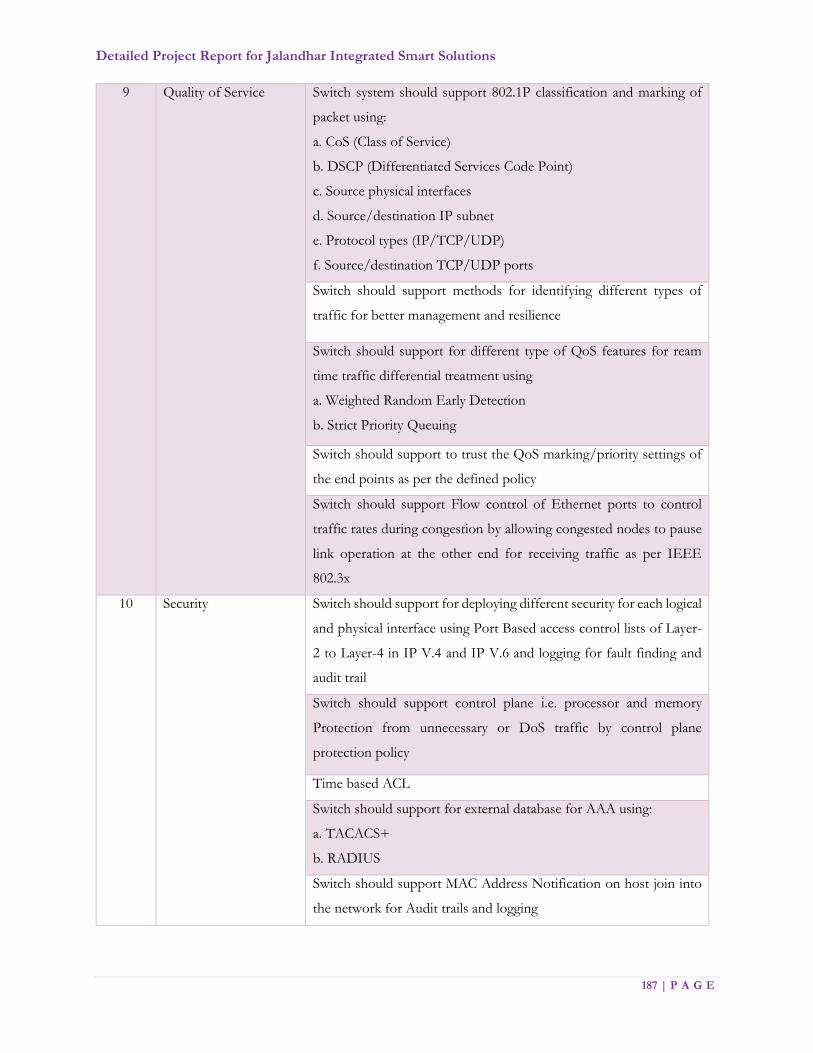
Detailed Project Report for Jalandhar Integrated Smart Solutions
187 | P A G E
9 Quality of Service Switch system should support 802.1P classification and marking of
packet using:
a. CoS (Class of Service)
b. DSCP (Differentiated Services Code Point)
c. Source physical interfaces
d. Source/destination IP subnet
e. Protocol types (IP/TCP/UDP)
f. Source/destination TCP/UDP ports
Switch should support methods for identifying different types of
traffic for better management and resilience
Switch should support for different type of QoS features for ream
time traffic differential treatment using
a. Weighted Random Early Detection
b. Strict Priority Queuing
Switch should support to trust the QoS marking/priority settings of
the end points as per the defined policy
Switch should support Flow control of Ethernet ports to control
traffic rates during congestion by allowing congested nodes to pause
link operation at the other end for receiving traffic as per IEEE
802.3x
10 Security Switch should support for deploying different security for each logical
and physical interface using Port Based access control lists of Layer-
2 to Layer-4 in IP V.4 and IP V.6 and logging for fault finding and
audit trail
Switch should support control plane i.e. processor and memory
Protection from unnecessary or DoS traffic by control plane
protection policy
Time based ACL
Switch should support for external database for AAA using:
a. TACACS+
b. RADIUS
Switch should support MAC Address Notification on host join into
the network for Audit trails and logging
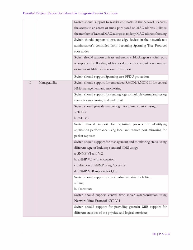
Detailed Project Report for Jalandhar Integrated Smart Solutions
188 | P A G E
Switch should support to restrict end hosts in the network. Secures
the access to an access or trunk port based on MAC address. It limits
the number of learned MAC addresses to deny MAC address flooding
Switch should support to prevent edge devices in the network not
administrator's controlled from becoming Spanning Tree Protocol
root nodes
Switch should support unicast and multicast blocking on a switch port
to suppress the flooding of frames destined for an unknown unicast
or multicast MAC address out of that port
Switch should support Spanning tree BPDU protection
11 Manageability Switch should support for embedded RMON/RMON-II for central
NMS management and monitoring
Switch should support for sending logs to multiple centralised syslog
server for monitoring and audit trail
Switch should provide remote login for administration using:
a. Telnet
b. SSH V.2
Switch should support for capturing packets for identifying
application performance using local and remote port mirroring for
packet captures
Switch should support for management and monitoring status using
different type of Industry standard NMS using:
a. SNMP V1 and V.2
b. SNMP V.3 with encryption
c. Filtration of SNMP using Access list
d. SNMP MIB support for QoS
Switch should support for basic administrative tools like:
a. Ping
b. Traceroute
Switch should support central time server synchronisation using
Network Time Protocol NTP V.4
Switch should support for providing granular MIB support for
different statistics of the physical and logical interfaces

Detailed Project Report for Jalandhar Integrated Smart Solutions
189 | P A G E
Switch should support for predefined and customized execution of
script for device mange for automatic and scheduled system status
update for monitoring and management
Switch should provide different privilege for login in to the system
for monitoring and management
Switch should support Real time Packet Capture using Wireshark in
real time for traffic analysis and fault finding
12 IPv6 features Switch should support for IP V.6 connectivity and routing required
for network reachability using different routing protocols such as:
a. OSPF V.3
b. BGP with IP V.6
c. IP V.6 Policy based routing
d. IP V.6 Dual Stack etc.
e. IP V.6 Static Route
f. IP V.6 Default route
g. Should support route redistribution between these protocols
Switch should support multicast routing in IP V.6 network using
PIMv2 Sparse Mode
Switch should support for QoS in IP V.6 network connectivity
Switch should support for monitoring and management using
different versions of SNMP in IP V.6 environment such as:
a. SNMPv1, SNMPv2c, SNMPv3
b. SNMP over IP V.6 with encryption support for SNMP Version 3
Switch should support syslog for sending system log messages to
centralised log server in IP V.6 environment
Switch should support NTP to provide an accurate and consistent
timestamp over IPv6 to synchronize log collection and events
Switch should support for IP V.6 different types of tools for
administration and management such as:
a. Ping
b. Trace route
c. VTY
d. SSH
e. DNS lookup
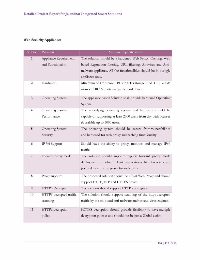
Detailed Project Report for Jalandhar Integrated Smart Solutions
190 | P A G E
Web Security Appliance:
Sl. No. Parameter Minimum Specifications
1 Appliance Requirement
and Functionality
The solution should be a hardened Web Proxy, Caching, Web
based Reputation filtering, URL filtering, Antivirus and Anti-
malware appliance. All the functionalities should be in a single
appliance only.
2 Hardware Minimum of 1 * 6-core CPUs, 2.4 TB storage, RAID 10, 32 GB
or more DRAM, hot-swappable hard drive
3 Operating System The appliance based Solution shall provide hardened Operating
System.
4 Operating System
Performance
The underlying operating system and hardware should be
capable of supporting at least 2000 users from day with licenses
& scalable up to 5000 users.
5 Operating System
Security
The operating system should be secure from vulnerabilities
and hardened for web proxy and caching functionality.
6 IP V6 Support Should have the ability to proxy, monitor, and manage IPv6
traffic.
7 Forward proxy mode The solution should support explicit forward proxy mode
deployment in which client applications like browsers are
pointed towards the proxy for web traffic.
8 Proxy support The proposed solution should be a Fast Web Proxy and should
support HTTP, FTP and HTTPS proxy.
9 HTTPS Decryption The solution should support HTTPS decryption
10 HTTPS decrypted traffic
scanning
The solution should support scanning of the https decrypted
traffic by the on-board anti-malware and/or anti-virus engines.
11 HTTPS decryption
policy
HTTPS decryption should provide flexibility to have multiple
decryption policies and should not be just a Global action
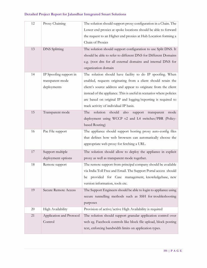
Detailed Project Report for Jalandhar Integrated Smart Solutions
191 | P A G E
12 Proxy Chaining The solution should support proxy configuration in a Chain. The
Lower end proxies at spoke locations should be able to forward
the request to an Higher end proxies at Hub Location forming a
Chain of Proxies
13 DNS Splitting The solution should support configuration to use Split DNS. It
should be able to refer to different DNS for Different Domains
e.g. (root dns for all external domains and internal DNS for
organization domain
14 IP Spoofing support in
transparent mode
deployments
The solution should have facility to do IP spoofing. When
enabled, requests originating from a client should retain the
client’s source address and appear to originate from the client
instead of the appliance. This is useful in scenarios where policies
are based on original IP and logging/reporting is required to
track activity of individual IP basis.
15 Transparent mode The solution should also support transparent mode
deployment using WCCP v2 and L4 switches/PBR (Policy-
based Routing)
16 Pac File support The appliance should support hosting proxy auto-config files
that defines how web browsers can automatically choose the
appropriate web proxy for fetching a URL.
17 Support multiple
deployment options
The solution should allow to deploy the appliance in explicit
proxy as well as transparent mode together.
18 Remote support The remote support from principal company should be available
via India Toll Free and Email. The Support Portal access should
be provided for Case management, knowledgebase, new
version information, tools etc.
19 Secure Remote Access The Support Engineers should be able to login to appliance using
secure tunnelling methods such as SSH for troubleshooting
purposes
20 High Availability Provision of active/active High Availability is required
21 Application and Protocol
Control
The solution should support granular application control over
web eg. Facebook controls like block file upload, block posting
text, enforcing bandwidth limits on application types.

Detailed Project Report for Jalandhar Integrated Smart Solutions
192 | P A G E
22 File download and size
restrictions
The solution should be capable of blocking specific files
downloads and based on size and per user group basis. It should
also provide option to block object using MIME File types.
23 IP based Access Control The solution should allow administrator to define access to
internet based on IP addresses, range of IP addresses, subnet and
CIDR basis. It should also support to be forced for
Authentication from Specific IP addresses, Subnet or CIDR's
24 User based Access
Control
The solution should support integration with active directory
and/or LDAP. This should allow administrator to define user or
group based access policies to Internet
25 Multiple Authentication
Server Support
The solution should support Multiple Auth Servers / Auth
Failover using Multi Scheme Auth (NTLM and LDAP). It should
also support authentication exemption.
26 Layer 4 Traffic
Monitoring
Should detect Phone Home attempts occurring from the entire
Network. It should support actions to allow traffic to & from
known malware addresses & should support from known
allowed & unlisted addresses & block traffic to & monitoring
suspected malware addresses.
27 Bandwidth restrictions The solution should support providing bandwidth limit/cap for
streaming media application traffic. This should be possible at
the Global level as well as at a per policy level.
28 Anti-Malware The appliance should support at least 2 industry known Anti
Malware/Anti-Virus engine that can scan HTTP, HTTPS and
adware, browser hijackers, phishing and pharming attacks to
FTP traffic for web based threats, that can range from more
malicious threats such as rootkits, Trojans, worms, system
monitors and Key loggers and as defined by the organizations
policy. Please mention the antimalware engine.
29 Malware Protection With dual AV/Anti-Malware engine scanning when a URL
causes different verdicts from the scanning engine the
appliance should perform the most restrictive action.
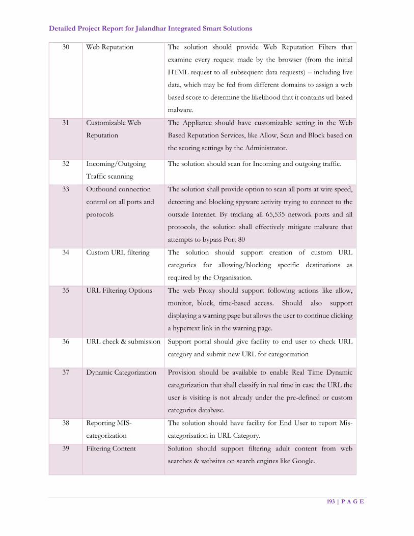
Detailed Project Report for Jalandhar Integrated Smart Solutions
193 | P A G E
30 Web Reputation The solution should provide Web Reputation Filters that
examine every request made by the browser (from the initial
HTML request to all subsequent data requests) – including live
data, which may be fed from different domains to assign a web
based score to determine the likelihood that it contains url-based
malware.
31 Customizable Web
Reputation
The Appliance should have customizable setting in the Web
Based Reputation Services, like Allow, Scan and Block based on
the scoring settings by the Administrator.
32 Incoming/Outgoing
Traffic scanning
The solution should scan for Incoming and outgoing traffic.
33 Outbound connection
control on all ports and
protocols
The solution shall provide option to scan all ports at wire speed,
detecting and blocking spyware activity trying to connect to the
outside Internet. By tracking all 65,535 network ports and all
protocols, the solution shall effectively mitigate malware that
attempts to bypass Port 80
34 Custom URL filtering The solution should support creation of custom URL
categories for allowing/blocking specific destinations as
required by the Organisation.
35 URL Filtering Options The web Proxy should support following actions like allow,
monitor, block, time-based access. Should also support
displaying a warning page but allows the user to continue clicking
a hypertext link in the warning page.
36 URL check & submission Support portal should give facility to end user to check URL
category and submit new URL for categorization
37 Dynamic Categorization Provision should be available to enable Real Time Dynamic
categorization that shall classify in real time in case the URL the
user is visiting is not already under the pre-defined or custom
categories database.
38 Reporting MIS-
categorization
The solution should have facility for End User to report Mis-
categorisation in URL Category.
39 Filtering Content Solution should support filtering adult content from web
searches & websites on search engines like Google.
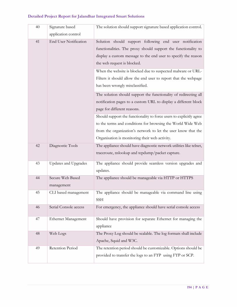
Detailed Project Report for Jalandhar Integrated Smart Solutions
194 | P A G E
40 Signature based
application control
The solution should support signature based application control.
41 End User Notification Solution should support following end user notification
functionalities. The proxy should support the functionality to
display a custom message to the end user to specify the reason
the web request is blocked.
When the website is blocked due to suspected malware or URL-
Filters it should allow the end user to report that the webpage
has been wrongly misclassified.
The solution should support the functionality of redirecting all
notification pages to a custom URL to display a different block
page for different reasons.
Should support the functionality to force users to explicitly agree
to the terms and conditions for browsing the World Wide Web
from the organization’s network to let the user know that the
Organisation is monitoring their web activity.
42 Diagnostic Tools The appliance should have diagnostic network utilities like telnet,
traceroute, nslookup and tcpdump/packet capture.
43 Updates and Upgrades The appliance should provide seamless version upgrades and
updates.
44 Secure Web Based
management
The appliance should be manageable via HTTP or HTTPS
45 CLI based management The appliance should be manageable via command line using
SSH
46 Serial Console access For emergency, the appliance should have serial console access
47 Ethernet Management Should have provision for separate Ethernet for managing the
appliance
48 Web Logs The Proxy Log should be scalable. The log formats shall include
Apache, Squid and W3C.
49 Retention Period The retention period should be customizable. Options should be
provided to transfer the logs to an FTP using FTP or SCP.

Detailed Project Report for Jalandhar Integrated Smart Solutions
195 | P A G E
50 User Reports Informative and exhaustive set of reports on User Activity and
URL filtering activities (GUI to report past activity, top usage
users and top malware threat)
51 Bandwidth Reports Reports on Bandwidth Consumed / Bandwidth Saved
52 Detailed logging Product to maintain detailed proxy access logs that can be
searched via filters, for easy location of any desired access of the
user and to see how the product dealt with it
53 Blocked by reputation
&malware reports
It should support reporting web requests blocked due to web
reputation & blocked by malware
54 Report Formats Solution should support generating a printer-friendly formatted
pdf version of any of the report pages. Should also support
exporting reports as CSV files.
55 Scheduling of Reports Solution should support to schedule reports to run on a daily,
weekly, or monthly basis.
56 System Reports Should support system reports to show CPU usage, RAM usage,
percentage of disk space used for reporting & logging.
57 Updates and Upgrades Support should cover all upgrades for the time period the
licenses and support purchased from principal vendor
Anti-APT
Sl. No. Minimum Specifications
1 Anti-APT solution should be appliance based and should offer a minimum throughput of 2
Gbps
2 Appliance should support at least 8*1Gbps ports
3 Appliance shall provide a separate management port and should also provide a web-based
GUI management
4 Appliance should provide at least 1 Million concurrent sessions or 1000 concurrent users
5 Appliance should be capable of working in Inline Blocking mode without depending on other
network components like a separate FW, IPS or Web Security Appliance
6 Appliance should have fail-open capabilities for all ports
7 Appliance should have redundant power supplies
8 Solution should be capable of blocking call backs to CnC Servers

Detailed Project Report for Jalandhar Integrated Smart Solutions
196 | P A G E
9 Solution should be capable of blocking threats based on both signatures and behaviour
10 Proposed solution's detection rules should be based on an extensible, open language that
enables users to create their own rules, as well as to customize any vendor-provided rules.
11 Proposed solution should be capable of blocking threats on the following protocols: HTTP,
HTTPS
12 The solution should be capable of executing MS Office Documents, Portable Documents,
Archive Files, Multimedia Files and executable binaries in a virtual sandbox environment
13 The solution should be capable of exempting specific hosts from specific compliance rules
and suppressing corresponding compliance events and alerts.
14 The solution should be capable of gathering Active Directory user identity information,
mapping IP addresses to username and passively gathering information about network
devices including but not limited to:
• Network protocols used, e.g. IPv6, IPv4
• Network services provided, e.g. HTTPS, SSH
• Open ports, e.g. TCP:80
• Client applications installed and type, e.g. Chrome - web browser
• Web applications access, e.g. Facebook, Gmail
• Risk and relevance ratings should be available for all applications
• Potential vulnerabilities
• Current User
• Device type, e.g. Bridge, Mobile device
• Files transferred by this device/user
15 The solution should be capable of whitelisting trusted applications from being inspected to
avoid business applications from being affected & in turn productivity
16 The solution should be capable of blocking traffic based on geo locations to reduce the attack
landscape and to protect communication to unwanted destinations based on geography
17 The sandbox should be appliance based with the ability to run multiple versions of 32 and
64-bit client and Server Windows within the same environment
18 All the devices shall be managed centrally and should be capable of
Centralized, life cycle management for all sensors
Aggregating all events and centralized, real-time monitoring and forensic analysis
of detected events
Must provide a highly customizable dashboard
19 The sandbox should be appliance based with the ability to run multiple versions of
Windows within the same environment

Detailed Project Report for Jalandhar Integrated Smart Solutions
197 | P A G E
20 The Sandbox should be a proprietary custom-built malware analysis solution and not open
source or generic sandbox
21
The Sandbox should be a proprietary custom-built malware analysis solution and not open
source or generic sandbox and should provide:
- analysis reports
- threat score of the sample
- ability to queue samples,
- impact analysis
- Global Threat Intelligence
- Sandbox shall be able to detect memory residing malware
22 The proposed solution shall have the capability to continuously track a file's disposition
based on global intelligence and do a retrospective block and alert if the file has exhibited
malicious traits globally even if the file hasn't started behaving maliciously locally
23 The solution should include protection against desktop and server & should support
minimum Windows 7 desktop, Windows server 2003 & 2008. Bidder should provide license
for 1000 window based PC/Servers.
Firewall with IPS & URL Filtering
Sl. No. Minimum Specifications
1 Hardware Architecture
The appliance-based security platform should be capable of providing firewall, application
visibility, and IPS functionality in a single appliance
The appliance should support at least 2 * 10G ports scalable up to 8x10G, the firewall should
be modular in nature so that it can be scalable
The appliance hardware should be a multicore CPU architecture with a hardened 64-bit
operating system to support higher memory
Proposed Firewall should not be proprietary ASIC-based in nature & should be open
architecture based on multi-core CPU's to protect & scale against dynamic latest security
threats.
2 Performance & Scalability
Should support at least 10 Gbps of production performance / multiprotocol combined firewall
& IPS throughput
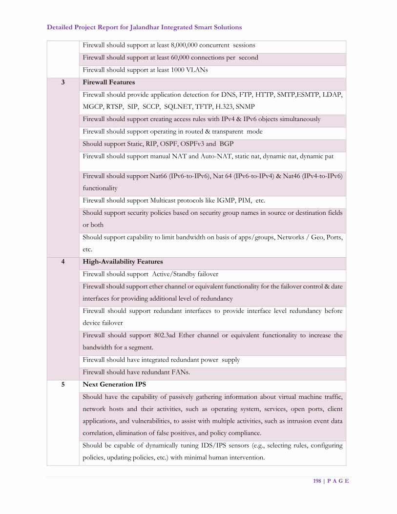
Detailed Project Report for Jalandhar Integrated Smart Solutions
198 | P A G E
Firewall should support at least 8,000,000 concurrent sessions
Firewall should support at least 60,000 connections per second
Firewall should support at least 1000 VLANs
3 Firewall Features
Firewall should provide application detection for DNS, FTP, HTTP, SMTP,ESMTP, LDAP,
MGCP, RTSP, SIP, SCCP, SQLNET, TFTP, H.323, SNMP
Firewall should support creating access rules with IPv4 & IPv6 objects simultaneously
Firewall should support operating in routed & transparent mode
Should support Static, RIP, OSPF, OSPFv3 and BGP
Firewall should support manual NAT and Auto-NAT, static nat, dynamic nat, dynamic pat
Firewall should support Nat66 (IPv6-to-IPv6), Nat 64 (IPv6-to-IPv4) & Nat46 (IPv4-to-IPv6)
functionality
Firewall should support Multicast protocols like IGMP, PIM, etc.
Should support security policies based on security group names in source or destination fields
or both
Should support capability to limit bandwidth on basis of apps/groups, Networks / Geo, Ports,
etc.
4 High-Availability Features
Firewall should support Active/Standby failover
Firewall should support ether channel or equivalent functionality for the failover control & date
interfaces for providing additional level of redundancy
Firewall should support redundant interfaces to provide interface level redundancy before
device failover
Firewall should support 802.3ad Ether channel or equivalent functionality to increase the
bandwidth for a segment.
Firewall should have integrated redundant power supply
Firewall should have redundant FANs.
5 Next Generation IPS
Should have the capability of passively gathering information about virtual machine traffic,
network hosts and their activities, such as operating system, services, open ports, client
applications, and vulnerabilities, to assist with multiple activities, such as intrusion event data
correlation, elimination of false positives, and policy compliance.
Should be capable of dynamically tuning IDS/IPS sensors (e.g., selecting rules, configuring
policies, updating policies, etc.) with minimal human intervention.
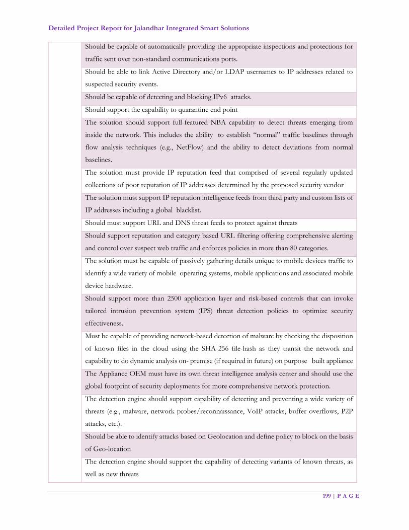
Detailed Project Report for Jalandhar Integrated Smart Solutions
199 | P A G E
Should be capable of automatically providing the appropriate inspections and protections for
traffic sent over non-standard communications ports.
Should be able to link Active Directory and/or LDAP usernames to IP addresses related to
suspected security events.
Should be capable of detecting and blocking IPv6 attacks.
Should support the capability to quarantine end point
The solution should support full-featured NBA capability to detect threats emerging from
inside the network. This includes the ability to establish “normal” traffic baselines through
flow analysis techniques (e.g., NetFlow) and the ability to detect deviations from normal
baselines.
The solution must provide IP reputation feed that comprised of several regularly updated
collections of poor reputation of IP addresses determined by the proposed security vendor
The solution must support IP reputation intelligence feeds from third party and custom lists of
IP addresses including a global blacklist.
Should must support URL and DNS threat feeds to protect against threats
Should support reputation and category based URL filtering offering comprehensive alerting
and control over suspect web traffic and enforces policies in more than 80 categories.
The solution must be capable of passively gathering details unique to mobile devices traffic to
identify a wide variety of mobile operating systems, mobile applications and associated mobile
device hardware.
Should support more than 2500 application layer and risk-based controls that can invoke
tailored intrusion prevention system (IPS) threat detection policies to optimize security
effectiveness.
Must be capable of providing network-based detection of malware by checking the disposition
of known files in the cloud using the SHA-256 file-hash as they transit the network and
capability to do dynamic analysis on- premise (if required in future) on purpose built appliance
The Appliance OEM must have its own threat intelligence analysis center and should use the
global footprint of security deployments for more comprehensive network protection.
The detection engine should support capability of detecting and preventing a wide variety of
threats (e.g., malware, network probes/reconnaissance, VoIP attacks, buffer overflows, P2P
attacks, etc.).
Should be able to identify attacks based on Geolocation and define policy to block on the basis
of Geo-location
The detection engine should support the capability of detecting variants of known threats, as
well as new threats
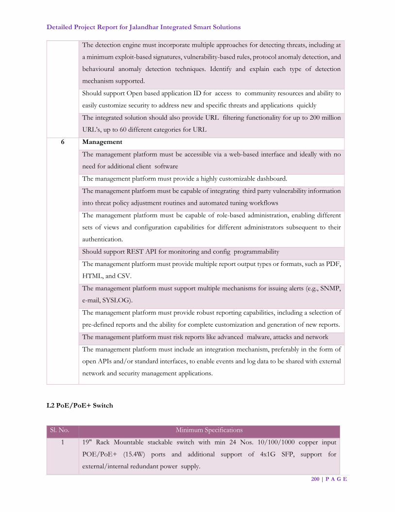
Detailed Project Report for Jalandhar Integrated Smart Solutions
200 | P A G E
The detection engine must incorporate multiple approaches for detecting threats, including at
a minimum exploit-based signatures, vulnerability-based rules, protocol anomaly detection, and
behavioural anomaly detection techniques. Identify and explain each type of detection
mechanism supported.
Should support Open based application ID for access to community resources and ability to
easily customize security to address new and specific threats and applications quickly
The integrated solution should also provide URL filtering functionality for up to 200 million
URL’s, up to 60 different categories for URL
6 Management
The management platform must be accessible via a web-based interface and ideally with no
need for additional client software
The management platform must provide a highly customizable dashboard.
The management platform must be capable of integrating third party vulnerability information
into threat policy adjustment routines and automated tuning workflows
The management platform must be capable of role-based administration, enabling different
sets of views and configuration capabilities for different administrators subsequent to their
authentication.
Should support REST API for monitoring and config programmability
The management platform must provide multiple report output types or formats, such as PDF,
HTML, and CSV.
The management platform must support multiple mechanisms for issuing alerts (e.g., SNMP,
e-mail, SYSLOG).
The management platform must provide robust reporting capabilities, including a selection of
pre-defined reports and the ability for complete customization and generation of new reports.
The management platform must risk reports like advanced malware, attacks and network
The management platform must include an integration mechanism, preferably in the form of
open APIs and/or standard interfaces, to enable events and log data to be shared with external
network and security management applications.
L2 PoE/PoE+ Switch
Sl. No. Minimum Specifications
1 19" Rack Mountable stackable switch with min 24 Nos. 10/100/1000 copper input
POE/PoE+ (15.4W) ports and additional support of 4x1G SFP, support for
external/internal redundant power supply.
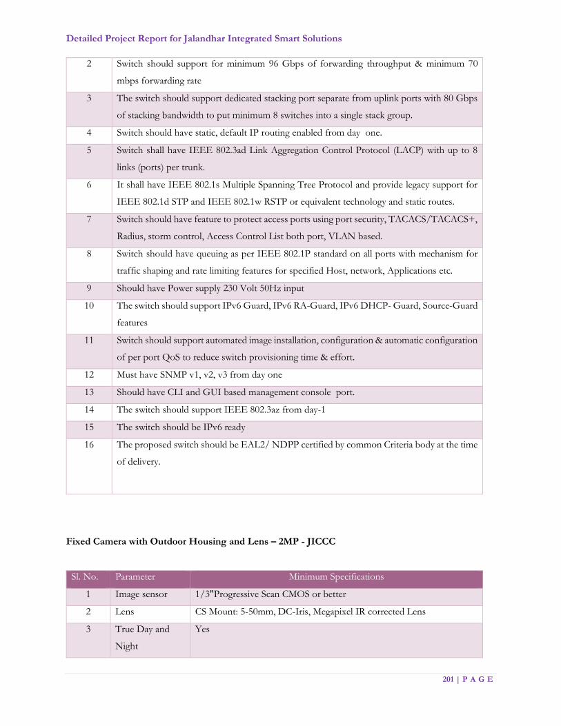
Detailed Project Report for Jalandhar Integrated Smart Solutions
201 | P A G E
2 Switch should support for minimum 96 Gbps of forwarding throughput & minimum 70
mbps forwarding rate
3 The switch should support dedicated stacking port separate from uplink ports with 80 Gbps
of stacking bandwidth to put minimum 8 switches into a single stack group.
4 Switch should have static, default IP routing enabled from day one.
5 Switch shall have IEEE 802.3ad Link Aggregation Control Protocol (LACP) with up to 8
links (ports) per trunk.
6 It shall have IEEE 802.1s Multiple Spanning Tree Protocol and provide legacy support for
IEEE 802.1d STP and IEEE 802.1w RSTP or equivalent technology and static routes.
7 Switch should have feature to protect access ports using port security, TACACS/TACACS+,
Radius, storm control, Access Control List both port, VLAN based.
8 Switch should have queuing as per IEEE 802.1P standard on all ports with mechanism for
traffic shaping and rate limiting features for specified Host, network, Applications etc.
9 Should have Power supply 230 Volt 50Hz input
10 The switch should support IPv6 Guard, IPv6 RA-Guard, IPv6 DHCP- Guard, Source-Guard
features
11 Switch should support automated image installation, configuration & automatic configuration
of per port QoS to reduce switch provisioning time & effort.
12 Must have SNMP v1, v2, v3 from day one
13 Should have CLI and GUI based management console port.
14 The switch should support IEEE 802.3az from day-1
15 The switch should be IPv6 ready
16 The proposed switch should be EAL2/ NDPP certified by common Criteria body at the time
of delivery.
Fixed Camera with Outdoor Housing and Lens – 2MP - JICCC
Sl. No. Parameter Minimum Specifications
1 Image sensor 1/3"Progressive Scan CMOS or better
2 Lens CS Mount: 5-50mm, DC-Iris, Megapixel IR corrected Lens
3 True Day and
Night
Yes

Detailed Project Report for Jalandhar Integrated Smart Solutions
202 | P A G E
4 Minimum
Illumination /
Light Sensitivity
Color: 0.3 lux F1.4 B/W: 0.08 lux F1.4 or Better
5 IR Filter Automatic Built in IR Cut filter
6 Shutter Speed 1s to 1/3000
7 Video
Compression
H.265 High, Main, Base profile and MJPEG
8 Resolutions and
frame rates
(H.265)
1920 x 1080
9 Video Streams Minimum 3
10 Power Supply Power over Ethernet (PoE/PoE+) IEEE 802.3af Class 2
11 Digital I/O (
Alarms)
DI x 1 DO x 1
12 Local storage SD Card Slot with 128GB Support
13 Image Settings Color, Brightness, Sharpness, Contrast, White balance, Image
Mirroring, Text and image overlay, Privacy mask, Rotation: 0°, 90°,
180°, 270°, Exposure control, Exposure zones, Fine tuning of
behaviour at low light, Mirror Image
14 Supported
Protocol
IPv4 & v6, HTTP, HTTPS, SSL/TLS, QoS Layer 3 DiffServ, FTP,
CIFS/SMB, SMTP, Bonjour, UPnP ,SNMPv1/v2c/v3(MIB-II), DNS,
DynDNS, NTP, RTSP, RTP, TCP, UDP, IGMP, RTCP, ICMP,
DHCP, ARP, SOCKS, SSH
15 Security IEEE 802.1x, IP Address Filter, Password Protection, Digest
Authentication
16 ONVIF Profile S
17 API The interface shall be available for integration with 3rd party analytics
and applications in public domain free of cost
18 Operating
Conditions
- 10°C to 50°C, Humidity 10–100% RH (condensing)
19 Privacy Mask Required with Minimum 2 Zones
20 Image
Configuration
The camera allows include/ exclude area in any shape in order to reduce
false alarms and bandwidth/ storage
21 GOV Length It is possible to vary the GOV length in the camera setting for better
control on bandwidth

Detailed Project Report for Jalandhar Integrated Smart Solutions
203 | P A G E
22 Wide Dynamic
Range
Minimum 120 dB True or Better
23 Event Triggers
Motion Detection, Edge storage events, External Input, Time
Scheduled, Camera Tampering, Software alarms.
The camera shall be able to send and received trigger directly from any
other camera without interface of VMS.
24 Event Actions FTP or HTTP or network share, EMAIL, Notification via HTTP to
other camera or device, Pre and post alarm video buffering, External
Output Trigger, PTZ Preset, Guard Tour
25 Firmware
Upgrade
The firmware upgrade shall be done though web interface, The
firmware is available free of cost
26 Embedded
Applications
The camera shall provide a platform allowing the upload of third party
applications into the camera
27 Memory 512 MB RAM, 256 MB Flash with Support for Edge Based analytics
from 3rd Party
28 Housing IP 66 Rated IK 10 rated for outdoor use
29 Certifications CE, FCC, IEC, EN, UL
30 Warranty 3 years OEM warranty
High Definition PTZ Dome Camera (JICCC building)
Sl. No. Parameter Minimum Specifications
1 Image Sensor 1/3” Progressive Scan CMOS or better
2 Operating Frequency Min 50 Hz
3 Day/ Night Operation Automatic with IR Cut Filter
4 Minimum Illumination Colour: 0.3 Lux @ 30 IRE
B/W": 0.01 @ 30 IRE or better
5 high-speed pan-tilt
functionality
360° endless pan range and a 180° tilt range
6 Optical Zoom 30x Minimum & 12x Digital Zoom, Total 360x Zoom or better
7 Lens 4.3-129 mm or better
8 Pan, tilt, manual and
present speed
0.5° - 350°/s or better
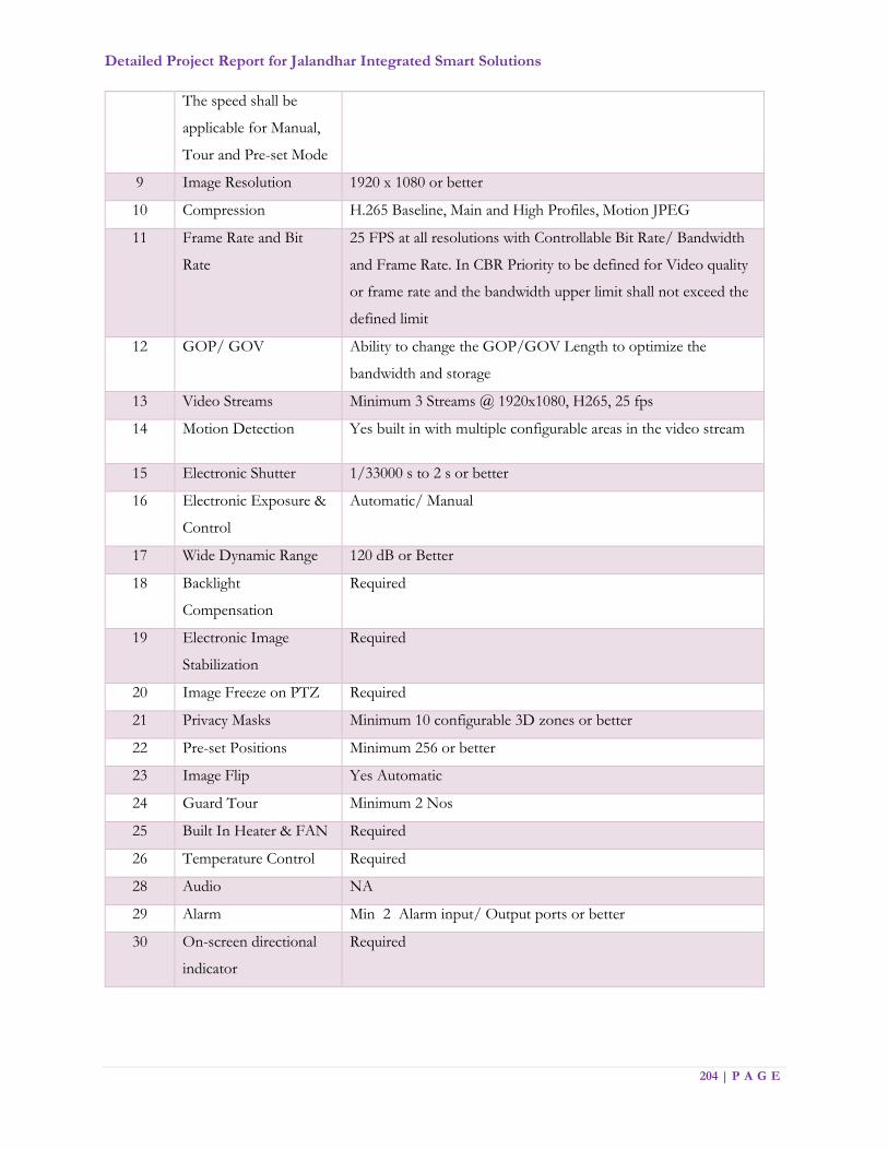
Detailed Project Report for Jalandhar Integrated Smart Solutions
204 | P A G E
The speed shall be
applicable for Manual,
Tour and Pre-set Mode
9 Image Resolution 1920 x 1080 or better
10 Compression H.265 Baseline, Main and High Profiles, Motion JPEG
11 Frame Rate and Bit
Rate
25 FPS at all resolutions with Controllable Bit Rate/ Bandwidth
and Frame Rate. In CBR Priority to be defined for Video quality
or frame rate and the bandwidth upper limit shall not exceed the
defined limit
12 GOP/ GOV Ability to change the GOP/GOV Length to optimize the
bandwidth and storage
13 Video Streams Minimum 3 Streams @ 1920x1080, H265, 25 fps
14 Motion Detection Yes built in with multiple configurable areas in the video stream
15 Electronic Shutter 1/33000 s to 2 s or better
16 Electronic Exposure &
Control
Automatic/ Manual
17 Wide Dynamic Range 120 dB or Better
18 Backlight
Compensation
Required
19 Electronic Image
Stabilization
Required
20 Image Freeze on PTZ Required
21 Privacy Masks Minimum 10 configurable 3D zones or better
22 Pre-set Positions Minimum 256 or better
23 Image Flip Yes Automatic
24 Guard Tour Minimum 2 Nos
25 Built In Heater & FAN Required
26 Temperature Control Required
28 Audio NA
29 Alarm Min 2 Alarm input/ Output ports or better
30 On-screen directional
indicator
Required

Detailed Project Report for Jalandhar Integrated Smart Solutions
205 | P A G E
31 Compression The camera shall for its H.265 implementation support scene
adaptive bitrate control, in order to lowering bandwidth and
storage requirements.
The camera shall support automatic dynamic GOP for optimal
bitrate utilization. The camera shall support automatic dynamic
ROI to reduce bitrate in un-prioritized regions.
32 Event Triggers The camera shall be able to send and received trigger directly from
any other camera without interface of VMS.
Live Stream Accessed, Motion Detection, Shock
Detection, Audio Detection, Network, Temperature, Manual
Trigger, Virtual Inputs, Alarm Inputs, PTZ: Error, Moving, Pre-
set Reached, Ready, Storage Disruption, Storage Recording,
System Ready, User schedule
33
Event Actions File upload via FTP, SFTP, HTTP and email
Notification via email, HTTP and TCP
Pre- and post-alarm video buffering, External output activation,
PTZ present, guard tour, Video recording to edge storage,
Day/night mode, Overlay text
34 Pixel Counter Built in
35 Edge Storage Built in SD card slot with support up to 128 GB with Class 10
speed
36 Storage The Cameras shall have the feature to directly record the videos/
images onto storage without any Software
37 Protocols At least IP, HTTP, HTTPS, SSL/TLS, TCP, ICMP,
SNMPv1/v2c/v3 (MIB-II), RTSP, RTP, UDP, IGMP, RTCP,
SMTP, FTP, DHCP, UPnP, ARP, DNS, DynDNS, SOCKS,
NTP, CIFS/SMB. IPv4 & IPv6 and Bonjour
38 Text Overlay Date & time, and a customer-specific text, camera name,
graphical image etc.
41
42
Security Password protection, IP address filtering, HTTPS encryption,
IEEE 802.1Xa network access control, Digest authentication,
User access log
43 Firmware Upgrade The firmware upgrade shall be done though web interface, The
firmware shall be available free of cost

Detailed Project Report for Jalandhar Integrated Smart Solutions
206 | P A G E
44 Logs The camera shall provide minimum 200 logs of latest connections,
access attempts, users connected, changes in the cameras etc.
Interface RJ 45, 100 Base TX
45 Enclosure Die Cast Aluminium, IK10 rated, IP66 rated, polycarbonate clear
dome and sunshield, PVC free complying to WEEE Standards
46 Mount Wall / Pole Mount
47
48
Power requirements Power over Ethernet (PoE/PoE+) IEEE 802.3at Type 2 Class 4,
max. 24 W, Typical 9W; 24 V DC max. 30 W
24 V AC, max. 40 VA or better
49 Operating Temperature -25 °C to 55 °C or better
50 Operating Humidity 10–95% RH (condensing) or better
51 Certification UL, CE, FCC
33 Embedded Applications The camera shall provide a platform allowing the upload of third
party applications into the camera
34 Application
Programmers Interface
The interface shall be available for integration with 3rd party
analytics and applications in public domain free of cost
35 Onvif S required
51 Warranty Min 3 Years OEM warranty
Online UPS
Sl. No. Parameter Minimum Specifications
1 Capacity Adequate capacity to cover all above IT Components at respective
location. Indicative capacity JICCC – 50 KVA, Viewing center – 10
KVA, Traffic Signals – 1KVA
2 Output Wave Form Pure Sine wave
3 Input Power Factor at
Full Load
>0.90
4 Input Three Phase 3 Wire for over 5 KVA
5 Input Voltage Range 305-475VAC at Full Load
6 Input Frequency 50Hz +/- 3 Hz
7 Output Voltage 400V AC, Three Phase for over 5 KVA UPS
8 Output Frequency 50Hz+/- 0.5% (Free running); +/- 3% (Sync. Mode)
9 Inverter efficiency >90%
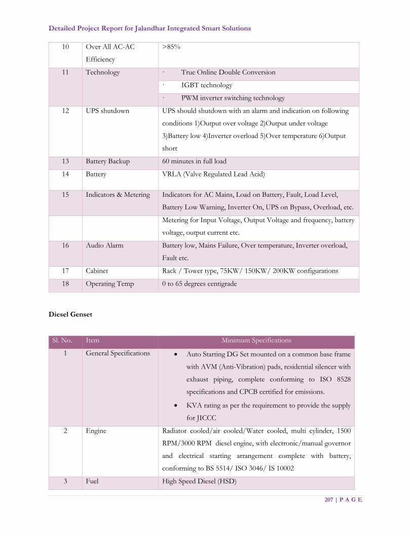
Detailed Project Report for Jalandhar Integrated Smart Solutions
207 | P A G E
10 Over All AC-AC
Efficiency
>85%
11 Technology
· True Online Double Conversion
· IGBT technology
· PWM inverter switching technology
12 UPS shutdown UPS should shutdown with an alarm and indication on following
conditions 1)Output over voltage 2)Output under voltage
3)Battery low 4)Inverter overload 5)Over temperature 6)Output
short
13 Battery Backup 60 minutes in full load
14 Battery VRLA (Valve Regulated Lead Acid)
15 Indicators & Metering Indicators for AC Mains, Load on Battery, Fault, Load Level,
Battery Low Warning, Inverter On, UPS on Bypass, Overload, etc.
Metering for Input Voltage, Output Voltage and frequency, battery
voltage, output current etc.
16 Audio Alarm Battery low, Mains Failure, Over temperature, Inverter overload,
Fault etc.
17 Cabinet Rack / Tower type, 75KW/ 150KW/ 200KW configurations
18 Operating Temp 0 to 65 degrees centigrade
Diesel Genset
Sl. No. Item Minimum Specifications
1 General Specifications Auto Starting DG Set mounted on a common base frame
with AVM (Anti-Vibration) pads, residential silencer with
exhaust piping, complete conforming to ISO 8528
specifications and CPCB certified for emissions.
KVA rating as per the requirement to provide the supply
for JICCC
2 Engine Radiator cooled/air cooled/Water cooled, multi cylinder, 1500
RPM/3000 RPM diesel engine, with electronic/manual governor
and electrical starting arrangement complete with battery,
conforming to BS 5514/ ISO 3046/ IS 10002
3 Fuel High Speed Diesel (HSD)

Detailed Project Report for Jalandhar Integrated Smart Solutions
208 | P A G E
4 Alternator Self-exciting, self-regulating type alternator rated at 0.8 PF or
better, 415 Volts, 3 Phase, 4 wires, 50 cycles/sec, 1500 RPM,
conforming to IS 4722/ BS 5000, Windings of 100% Copper, class
H insulation, Protection as per IP 23.
5 AMF (Auto Main
Failure) Panel
AMF Panel fitted inside the enclosure, with the following: It
should have the following meters/indicators:
· Incoming and outgoing voltage
· Current in all phases
· Frequency
· KVA and power factor
· Time indication for hours/minutes of operation
· Fuel Level in fuel tank, low fuel indication
· Emergency Stop button
· Auto/Manual/Test selector switch
· MCCB/Circuit breaker for short-circuit and overload
protection
· Control Fuses
· Earth Terminal
· Any other switch, instrument, relay etc. essential for
Automatic functioning of DG set with AMF panel
6 Acoustic Enclosure The DG set shall be provided with acoustic enclosure / canopy to
reduce the sound level and to house the entire DG set (Engine &
Alternator set) assembly outside (open-air). The enclosure must be
weather resistant powder coated, with insulation designed to meet
latest MOEF/CPCB norms for DG sets, capable to withstand
climate. The enclosure must have ventilation system, doors for
easy access for maintenance, secure locking arrangements etc.
7 Fuel Tank Capacity It should be sufficient and suitable for containing fuel for
minimum 12 hours continuous operation, Complete with level
indicator, fuel inlet and outlet, air vent, drain plug, inlet
arrangement for direct filling and set of fuel hoses for inlet and
return.

Detailed Project Report for Jalandhar Integrated Smart Solutions
209 | P A G E
7.3. .2 Network Backbone
i. The MSI shall provide the network with sufficient capacity available on Lease to JSCL for
entire project duration for connectivity from field locations to data center and from Data
Center to Disaster Recovery site.
ii. The MSI shall provide network connectivity at all required locations as mentioned in the
document. No location shall be left un-covered irrespective of existing network is available
or new network has to be laid
iii. MSI shall make a third party agreement with service provider and JSCL.
iv. In case if network is not available at particular location, MSI has to make an agreement
with Service Provider to provide network connectivity from required location.
v. The MSI shall provide end to end connectivity from all locations to Central Location in
Data Centre through various technologies mentioned here but not limited to Point to
Point / SD-WAN / MPLS-VPN etc. over fibre #
vi. The MSI shall be responsible to provide all Active / Passive equipment’s from Central
Location to Last point of connectivity
vii. The MSI shall upgrade the equipment’s free of cost, if required in future, to ensure that
services run smoothly and SLA is not breached
viii. The MSI shall be responsible to provide any Monitoring / Managing Software which shall
be required to monitor/ manage the Leased network
ix. All the Locations must be connected in Ring till the last point of connectivity from two
different sides The Leased network shall be future scalable and support upgrade in terms
of network, bandwidth and field components etc.
x. The MSI shall be responsible for O&M of leased network for the said period from the
date of lease of network
xi. Any addition in the number of locations shall need to be connected as per the agreed terms
and conditions for already connected sites. Same terms and conditions shall be applicable
for change or removal of any site from earlier selected sites
xii. Preventive and regular checks of power plant battery, generator, ac & remote alarm units
xiii. Maintaining history of events, analysis and reporting, public liaison with concerned
authority

Detailed Project Report for Jalandhar Integrated Smart Solutions
210 | P A G E
7.4. CCTV City Surveillance
This Component covers planning & implementation of the Surveillance system comprising cameras
and other field equipment at identified locations. Actual placement of pole & number of cameras at
each location, type of cameras, fixation of height & angle for the cameras to ensure maximum coverage
shall be done in consultation with Jalandhar Police Department.
MSI along with Jalandhar police shall talk to nearby private/public property owners and get
permissions to place the junction boxes. These junction boxes may be placed on terrace or
underground parking spaces or mounted on wall/ceiling in the identified property. The necessary
accessories shall be part of cost estimates.
The surveyors shall also finalize the approximate location of foundation for junction box and camera
poles. The route for all the underground cable laying shall be finalized during this survey (wherever
required).
System shall provide inter-operability of hardware, operating system, software, networking, printing,
database connectivity, reporting, and communication protocols. MSI shall prepare the detailed report
for field level requirements e.g. Cameras (types & numbers), Camera Mounting requirements, Power
Requirements, Connectivity Requirements etc. for perusal of JSCL and designated agency. MSI shall
also study the process requirements of police to configure and customize the system and implement
the processes as per the defined project timelines.
Every detail, finalized during the survey, shall be demarcated on an AutoCAD drawing and submitted
to JSCL or designated agency and Jalandhar police in the form of a detailed site survey report along
with other details for its approval in the format below
Sample of AutoCAD diagram is as follows:
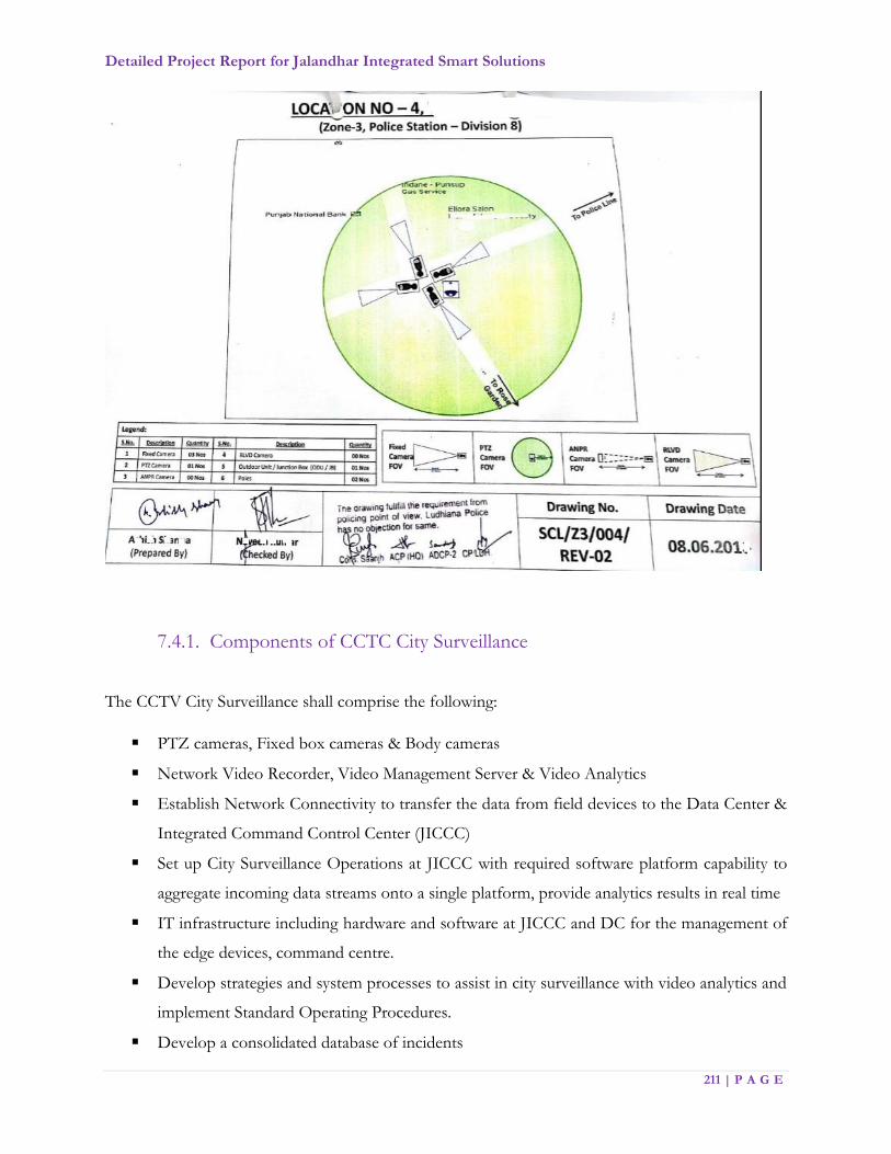
Detailed Project Report for Jalandhar Integrated Smart Solutions
211 | P A G E
7.4.1. Components of CCTC City Surveillance
The CCTV City Surveillance shall comprise the following:
PTZ cameras, Fixed box cameras & Body cameras
Network Video Recorder, Video Management Server & Video Analytics
Establish Network Connectivity to transfer the data from field devices to the Data Center &
Integrated Command Control Center (JICCC)
Set up City Surveillance Operations at JICCC with required software platform capability to
aggregate incoming data streams onto a single platform, provide analytics results in real time
IT infrastructure including hardware and software at JICCC and DC for the management of
the edge devices, command centre.
Develop strategies and system processes to assist in city surveillance with video analytics and
implement Standard Operating Procedures.
Develop a consolidated database of incidents
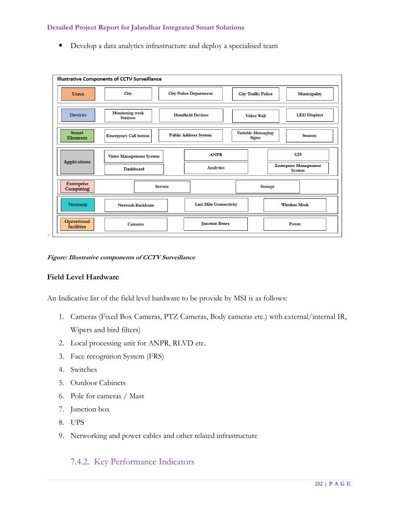
Detailed Project Report for Jalandhar Integrated Smart Solutions
212 | P A G E
Develop a data analytics infrastructure and deploy a specialised team
`
Figure: Illustrative components of CCTV Surveillance
Field Level Hardware
An Indicative list of the field level hardware to be provide by MSI is as follows:
1. Cameras (Fixed Box Cameras, PTZ Cameras, Body cameras etc.) with external/internal IR,
Wipers and bird filters)
2. Local processing unit for ANPR, RLVD etc.
3. Face recognition System (FRS)
4. Switches
5. Outdoor Cabinets
6. Pole for cameras / Mast
7. Junction box
8. UPS
9. Networking and power cables and other related infrastructure
7.4.2. Key Performance Indicators

Detailed Project Report for Jalandhar Integrated Smart Solutions
213 | P A G E
The KPIs for CCTV Surveillance shall be the following:
a. City Surveillance should cater to an effective Monitoring and Management with appropriate
decision support mechanisms.
b. City surveillance must ensure a pro-active 24*7 monitoring of PAN city parameters that
capture video footages of all junctions across the road network of Jalandhar and project the
feeds to the proposed Command and Control center without time lag on real time basis.
c. City Surveillance System must ensure and provide a secure and safe environment for the
citizens with intelligent and effective use of video analytics and integrated platform for all
concerned departments.
d. The surveillance prime equipment i.e. High Definition Camera units which includes fixed
box, and PAN-Tilt-Zoom, must be located at a suitable position wherein the required area
is properly capture. The intensity of captured footage should be enough to sustain the clarity
as per the required zooming levels. Industry leading practices must be adopted during the
implementation phase w.r.t positioning and mounting the cameras, poles and junction boxes.
e. The surveillance system shall be to provide proactive security as opposed to reactive security
on PAN city basis with a clear defined objective of each HD camera unit.
f. The surveillance System shall provide inter-operability of hardware, operating system,
software, networking, printing, database connectivity, reporting, and communication
protocols.
g. It has to be ensure that the pole is well place for vibration resistance adhering to the road
safety norms. In addition, the poles erected to mount cameras are good, both qualitatively
and aesthetically.
h. Appropriate branding / color-coding of junction boxes should be done, to warn mischief
mongers against tampering with the equipment at the junction with the needful operational
equipment. Cameras needs to be protected from the on field challenges of weather, physical
damage and theft.
i. Video Management System must allow users to view a count of analytics events on the video
pane while video is being display.
j. Each intersection should be fitted with outdoor cabinets dimensioned to host all equipment
necessary to operate enforcement systems and traffic surveillance systems
k. The data retention of minimum 30 days has to be maintained at JICCC.

Detailed Project Report for Jalandhar Integrated Smart Solutions
214 | P A G E
l. The city surveillance system must ensure real time and event based monitoring of the city,
situation/ rule based alerts including early warnings for prevention and avoidance of
unwanted incidents like riots, flooding, etc.
m. The system should support automated response based on events including communication
of alerts to relevant authorities like Fire, Hospitals, etc. for swift response in case of
emergencies.
n. The system should have access to historic video data for investigative purposes as stated
earlier.
o. IP based Public Address System shall also be used as part of the information dissemination
system at various locations in the city. These systems shall be deployed at identified junctions
to make public interest announcements.
p. The feed from video shall be accessed from multiple locations as mentioned in list of viewing
centres.
q. Wipers and bird filters shall be installed for all the cameras
7.4.3. Functional Requirements
Requirements:
All CCTV hardware products (Model wise) offered in the project should be min UL, CE, FCC,
RoHS certified
The OEM for CCTV Camera should have technical support presence with its employees on
its payroll in India. This will ensure long term after sales support & spare support from the
OEM. MSI to produce documentary proof to establish the eligibility
The OEM should have CMMI certification
OEM should be in the well repeated in Video surveillance equipment manufacturing and
deployment
Local Service/support must be available
The server sizing shall be done with maximum of 70% utilization
Edge level processing shall be planned to reduce use of network bandwidth and improve
faster processing. For example, Face Recognition System, ANPR, SVDS (with ANPR) etc.

Detailed Project Report for Jalandhar Integrated Smart Solutions
215 | P A G E
Figure: Illustrative representation of CCTV Surveillance
Functional Requirements:
Jalandhar City Surveillance System shall consist of:
a) PTZ Cameras, Fixed Box Cameras, PTZ cameras and Body cameras etc.
b) Video Management System (VMS) including central software application.
c) Camera Accessories i.e., Power Supplies, Cable, Connectors and associated accessories
for an integrated system.
The cameras implemented as part of this project shall be rated for operations in outdoor
environment (for outdoor installations) and depending on the objective/application, shall be
of different configurations including PTZ or fixed cameras.
All the Cameras shall be IP based.
Cameras shall have an integral receiver/driver that shall be capable of controlling pan-tilt,
zoom and focus locally and also remotely from the JICCC.
All cameras shall support real-time video content analysis.
Event (alarm) Handling: -
a) The camera shall be capable of recording an event as pre and post event images to on-
board SD Media Card and on IP BASED NVR. Events may be triggered using camera
motion detection or from an external device input such as a relay.
Detailed Project Report for Jalandhar Integrated Smart Solutions
216 | P A G E
b) When triggered from an external input or the camera’s motion detector, the camera shall
be capable of sending JPEG images via e-mail and/or sequences of images to an FTP
server or on-board compact flash and IP BASED NVR.
c) A relay output shall be available upon the activation of the camera’s motion detector or
external relay input. The relay output may also be manually activated from the live view
screen.
Video Management System (VMS)
Video Management System (VMS) shall bring together physical security infrastructure and operations
and shall use the IP network as the platform for managing the entire surveillance system. End users
shall have rapid access to relevant information for analysis.
This shall allow operations managers and master system integrator (MSI) to build customized video
surveillance networks that meet their exact requirements. Software suite shall be a scalable and flexible
video management system that could be easily managed and monitored. Scalable system shall permit
retrieval of live or recorded video anywhere, anytime on a variety of clients via a web browser interface.
Video management server, on which the VMS is hosted upon, shall run seamlessly in the background
to manage connections, access and storage. Video management server shall accept the feed from IP
Camera installed at field locations. Server shall stream incoming video to a connected storage. VMS
shall support video IP fixed colour / B &W cameras, PTZ / Dome cameras, infrared cameras, low
light/IR cameras and any other camera that provides a composite PAL video signal.
General requirements:
Central software application to be installed at the JICCC shall be able to run on any PC based
on standard operating systems and shall be license free.
Video Management System (VMS) shall be non-proprietary and open ended to support
integration with JICCC platform.
Perpetual licenses with Software Assurance shall be procured
Central Application Server shall allow user to view live video stream.
Software shall consist of a single client application and the client software shall not be
dependent on, nor require any connection to, a central management or configuration server.
The client software shall be installable without any need for software or hardware license.
Dock able windows shall include:
Detailed Project Report for Jalandhar Integrated Smart Solutions
217 | P A G E
1. Site Explorer
2. Alarms/Events window
3. PTZ and advanced telemetry functions
4. Monitors window
5. Maps window
The system shall support a distributed architecture with no single point of failure.
Video shall normally stream direct from camera to client; streaming via a proxy or intermediate
server shall not be the normal function of the system but may be selected as an option.
A client need not ask “permission” to connect to a camera. The handshake between client and
camera shall be done directly.
There shall be no single management server. System management shall be distributed
throughout the system.
VMS shall allow the overlay of time and date and site information on live video panes, either
on all panes, or selected pane only. In addition, the overlay may consist of a user-provided
transparent PNG or JPEG file.
VMS shall allow users to view live video and review recorded video at the same time.
VMS shall be ONVIF compliant.
Users shall be able to display any camera view (virtual pre-set).
VMS shall allow users to reveal the hidden zone in live video if the user has the appropriate
permission.
Users shall be able to save the current zoom/scroll position as a camera view (virtual pre-set).
Administrators shall be able to configure hidden zones on fixed cameras.
VMS shall allow the display of analytics levels on video.
Users shall be able to take a snapshot of one image or all images currently displayed and saved
as a bitmap or JPEG image to a configurable location. This should include zoomed images.
Users shall be able to print a snapshot of an image displayed in a video pane direct on a printer
(colour or grayscale, depending on printer).
Users shall be able to replay currently viewed live video by a single mouse click for replays
from 10, 15 or 30 seconds before current time or from alarm time.
Users shall be able to configure the size for text and icons displayed on video panes. Text and
icons can be fixed size or adjust automatically when video pane size changes.
In the event of the video connection failing, the Video Management System shall display a
clear error message with the option to also display the last video frame received.

Detailed Project Report for Jalandhar Integrated Smart Solutions
218 | P A G E
Event Counting: The Video Management System shall allow users to view a count of analytics
events on the video pane while video is being displayed. The Video Management System shall
allow users to reset the event count for a camera.
The Video Management System shall support binary inputs on IP Cameras, encoders,
decoders and alarm panels.
The Video Management System shall support video loss alarm inputs.
The Video Management System shall support network loss alarm inputs.
The Video Management System shall support fault alarm inputs, including:
a) Raid degraded
b) License failure
c) Recording failure
d) Redundant power failure
e) Redundant network failure
The Video Management System shall support analytics alarm inputs, with separate events for
each analytics filter.
The Video Management System shall support alarm inputs from third party systems.
The Video Management System shall enable multiple alarm inputs (detectors) to be grouped
into an alarm zone.
The Video Management System shall support inputs (detectors) that do not cause an alarm to
be generate.
The Video Management System shall support ‘AND’ logic between detectors so that the alarm
input is activated only when both detectors are activated with a defined time period.
The Video Management System shall support detectors that are activated and deactivated by
different inputs e.g. activate on a binary input from one device and deactivated on a binary
input from another device.
Users shall be able to dock the alarm viewing window below the Live View or Playback View
windows.
Users shall be able to sort the alarm information in various ways by clicking on column
headings.
The Video Management System shall support set and unset of alarm zones such that alarms
are only generated when the alarm zone is set.
Users shall be able to configure the time scheduled for each alarm zone – different start and
end times for each day and multiple time per day.

Detailed Project Report for Jalandhar Integrated Smart Solutions
219 | P A G E
Users shall be able to define specific dates and times within time schedules so that exceptions
for holidays etc. can be specify.
The Video Management System shall enable the same time schedule to be apply to multiple
zones.
Users shall have the option of restoring the previous view after an alarm has been clear.
Users shall be able to manually set and unset zones.
Users shall be able to isolate faulty alarm inputs (detectors) such that they do not cause false
alarms. Users shall be able to easily identify which alarm inputs are isolate and the reason for
isolation.
The Video Management System shall enable zones to be set and unset on an event.
The Video Management System shall enable detectors to be isolated and restored on an event.
Users shall be able to specify a priority for each alarm zone (1-10.).
Users shall be able to configure the alarm sound for all alarm zones in a site or for each alarm
zone individually. Sound can be from any .wav file and can be sounded once or repeated while
the alarm is active.
The Video Management System shall allow alarms to be configure to require text from a user
at the point of acknowledging and at the point of clearing.
The Video Management System shall allow an alarm procedure document (.html, text or URL)
to be associated with a site or to an individual alarm zone. This procedure document shall be
display when an alarm happens.
a) Users shall be able to configure the actions that should be performed when an alarm
occurs:
b) Show video from camera, camera view or salvo in specified monitors
c) Stop video when alarm cleared
d) Move camera to pre-set position
e) Send email to multiple recipients, with option to include snapshots
f) Perform a relay action automatically
g) Start recording one or more camera – records for specified duration
h) Auto-protect recording from a specified duration before the alarm
Users shall be able to configure a second authorizing user for alarm clearing and relay actions
– second user has to enter a password to authorize these functions.
The Video Management System shall support the following for 3rd Party cameras through
native protocols and / or ONVIF:
Detailed Project Report for Jalandhar Integrated Smart Solutions
220 | P A G E
a) Motion detection events
b) Record on motion
c) Video loss
d) Network loss
e) Change video quality on event, including frame rate, resolution and bitrate
Users shall be able to configure an unlimited number of alarm groups each containing a set of
alarm zones and/or detectors.
For each user or user group, it shall be possible to associate one or more video panes with
each alarm group. This should also include analog monitors.
Users shall be able to choose a display mode for alarm video. As multiple alarms come in, the
video can either be “cascaded” across the chosen viewing panes or “queued” behind the
chosen viewing panes. As alarms are clear, the associated video is clear from the chosen
viewing panes. Cascaded video can either remain in the same video pane until cleared, or can
move to the first available pane, as earlier alarms are clear.
When all alarm video is clear from a viewing pane the Video Management System shall display
video and layout being view before any alarm was display.
The Video Management System shall remove any black screen monitoring analogue monitors
from the normal site hierarchy.
The Video Management System shall have permissions to determine which users or user
groups get access to which alarm groups and which windows are used to display alarm video.
Users shall be able to configure any of the available viewing panes or analogue monitors as a
spot monitor for viewing significant live footage.
The Video Management System shall provide a toolbar option on all live viewing panes to
copy the current video stream into the spot monitor.
The Video Management System shall keep an audit record of what video was started and
stopped in the spot monitor, by which user and what times.
The Video Management System shall allow the video sequence that was view in the spot
monitor by a selected user in a selected time period to be exported as a single incident.
Users shall be able to review all video watched by a selected user in a selected time period in
an incident player. The video should be played back as one sequence in a single video pane.
The Video Management System shall generate an alarm if any of the detectors within an alarm
zone are activate.
Detailed Project Report for Jalandhar Integrated Smart Solutions
221 | P A G E
The Video Management System shall not generate new alarms for subsequent detector
activations within the same zone so that the user only has one alarm to handle.
The Video Management System shall alert new alarms with flashing icon and optionally a
sound.
The Video Management System shall automatically perform the actions configured for the
alarm zone or detector:
a) Show video from camera, camera view or salvo in specified video panes or monitors
b) Move camera to pre-set position
c) Stop video when alarm cleared
d) Send email to multiple recipients
e) Perform a relay action
f) Start recording one or more cameras
g) Auto-protect recording from a specified duration before the alarm
When all alarm video is cleared from a viewing pane the Video Management System shall
display video and layout being viewed before any alarm was displayed.
From a looped replay, users shall be able to quickly jump to continuous replay from the alarm
time.
The users shall be able to display a map showing the location of the alarm.
Users shall be able to view pending alarms in a list ordered by priority and time.
Users shall be able to filter the alarm list to show alarms only from specific areas (sites and
zones.).
The Video Management System shall allow users to acknowledge alarms, entering alarm
response text as required.
The Video Management System shall allow users to edit the alarm response text at any time
before the alarm is cleared.
The Video Management System shall allow users to clear alarms, entering alarm response text
as required.
Users shall be able to find historical alarms matching specified criteria:
a) Alarm type
b) Alarm state (new, acknowledged, cleared)
c) From site(s)
d) From alarm zones(s)
e) User(s) who acknowledged or cleared

Detailed Project Report for Jalandhar Integrated Smart Solutions
222 | P A G E
f) Time range
The Video Management System shall be able to escalate alarms to other user groups if the
alarm is not acknowledged within a pre-defined time period.
The Video Management System shall be able to escalate alarms to other user groups if the
alarm is not cleared within a pre-defined time period.
The Video Management System shall support different escalation time periods for different
alarm priorities.
The Video Management System shall be able to propagate an alarm to other areas (zones) if
the alarm is not acknowledged within a pre-defined time period.
Users shall be able to produce reports of historical alarms and events and export to RTF or
CSV formats.
Users shall be able to authorize an alarm to be clear, by a second user entering a password.
Users shall be able to view live or recorded video associated with the alarm.
The Video Management System shall ensure that alarms are held on an alarm server, not on a
user’s PC.
The Video Management System (VMS) shall support integration with external data sources.
An external Data Source shall be defined as any text string up to 320 characters.
The VMS shall support up to 1 external data record every second.
The VMS shall support up to 2 million data records.
The VMS shall support the ability to search and filter data records using the following:
a) A partial text string to search data record
b) Source IP address of data
c) Name of Data source
The VMS shall allow for the association of data records with video data.
Integration shall be available via a freely available open interface. The interface shall be via a
software development kit.
Users shall be able to configure relay actions using binary outputs on IP Cameras, encoders
and decoders.
Users shall be able to configure relay actions using external outputs to 3rd party systems.
The relay activation shall be pulsed with a configurable pulse time period.
The Video Management System shall support latched relay outputs.
Users shall be able to associate relay actions with specific cameras so that the actions are readily
available when video is displayed from that camera.
Detailed Project Report for Jalandhar Integrated Smart Solutions
223 | P A G E
The Video Management System shall perform relay actions on alarm and event.
The Video Management System shall be able to perform relay actions on a time-schedule.
The Video Management System shall automatically check for devices not on the network and
notify users when not available.
It shall be possible to define the users who get notified if devices become unavailable.
Users shall be able to manage the bandwidth used for network scans by configuration of:
a) Monitor period (mins)
b) Minimum check interval (msec)
c) Perform fast check on log in
d) Perform fast check on refresh
The Video Management System shall scan for devices using any combination of IP broadcast
addresses, individual IP addresses or ranges of IP addresses.
Users shall be able to turn off scanning of devices.
Users shall be able to set sites to offline mode. In this mode, all automatic communication
with the site will be halted, while still allowing requested traffic.
Users shall be able to manually refresh any diagnostics view.
The Video Management System shall notify users when device times are not synchronized
with the viewing PC (more than 60 seconds out).
The Video Management System shall provide a support information tool, which gathers
together log files and site database into a zip file.
Users shall be able to configure named user groups. A group can be granted administrator
rights:
a) Full (can configure everything)
b) Restricted (can configure everything except users and groups)
c) No configuration rights (limited user functions only)
The Video Management System shall be able to hide administration options from normal
users. The user interface shall be cleanly split into administrative functions and operational
functions. Users who do not have administrative rights shall get a much simpler interface so
that they are not confused by visible but disabled features.
Users shall be able to configure named user accounts and allocate them to user groups.
Users shall be able to enable and disable user accounts.
Users shall be able to set-up a user to use either machine OS standard authentication or a
password when he logs into the Video Management System.

Detailed Project Report for Jalandhar Integrated Smart Solutions
224 | P A G E
Users shall be able to limit the total number of video streams (live or recorded) that a user or
member of a user group can display at once.
Users shall be able to limit the number of time-based thumbnail images that a user or member
of a user group will display at once.
Users shall be able to allocate each user group or user a priority that is used when controlling
PTZ cameras.
Users shall be able to grant global permissions to user groups or users (global permissions do
not apply to specific objects such as cameras):
a) PTZ hold (allows a user to keep control of a PTZ camera when not moving it)
b) Video lockout (allows a user to perform a video lockout on any site of camera)
Users shall be able to grant permission for user groups and/or users to access any object in
the system (sites, cameras, monitors, salvos, alarm zones, detectors and relays.) For each
object access can be limited by function: -
a) List – see object in the user interface
b) View – view video from cameras, sequences, salvos and guard tours
c) Transmit audio (speak) to a camera
d) Playback recording from a camera or salvo
e) Record – make an instant recording of a camera
f) Export video clips or take snapshots from a camera
g) Control a PTZ camera
h) Display video on a monitor or video wall or activate a relay
i) Respond to alarms from an alarm zone
j) Hidden zone (live or playback) – access video behind a hidden zone
k) Audio (live or playback) – receive audio from a device
l) Set and unset an alarm zone
m) Isolate and restore a detector
n) Work offline
o) Configure pre-sets and access the camera menus
Users shall be able to reset access permissions on individual objects to use the access
permissions of their parent site.
Users shall be able to configure application settings specific to each PC,
a) Enable or disable scheduled tasks
b) Enable or disable the application as the topmost window

Detailed Project Report for Jalandhar Integrated Smart Solutions
225 | P A G E
c) Location for snapshot images
d) Format of snapshot image (bitmap or JPEG)
e) Folder for snapshot image
f) Replay incident in live or Playback view
g) Use software or hardware assisted video renderer
h) Use de-interlace filtering on live view by default
i) Use de-interlace filtering on playback by default
j) Set video de-interlacing
k) Enable or disable use of a CCTV keyboard
l) Serial port for CCTV keyboard
m) CCTV keyboard type
n) Video pane text scale factor (% of the default text size)
o) Resize text on video panes in proportion to video pane size
p) Video pane icon size (normal, medium, large)
q) Select icon size on video panes in proportion to video pane size
r) Date / time display on video panes (none, all, selected)
s) Load bookmarks on start up
t) Spot monitor (external monitor or specified video pane)
u) Protect recordings by default when exporting
v) Write date and time on exported recordings
Users shall be able to prevent simultaneous listen and speak (full duplex audio).
Users shall be able to configure the use of buffered playback when reviewing recordings.
Users shall be able to enable or disable alert messages.
Users shall be able to log into the Video Management System manually.
It shall be possible to start the Video Management System from the command line with the
following options:
a) Username and password
b) Normal, full screen or video-only modes
c) Site database
The Video Management System shall allow users to log out and log in without closing the
application.
The Video Management System shall have an option to require all users to re-enter their
password when logging out.
Detailed Project Report for Jalandhar Integrated Smart Solutions
226 | P A G E
The Video Management System shall remember display settings on a PC for each user at log
off and restore settings at log in:
a) Which cameras are displayed in which video panes
b) PTZ controls displayed
c) Map window position
d) Alarm window position
e) Video window positions (default hidden)
f) Main window size and position and site explorer width
g) Recording calendar displayed
Users shall be able to change their own password (if given write permission to the site
database).
Users shall be able to change their default location on the tree hierarchy.
Users shall be able to lockout all other users preventing them from viewing or recording video
from a selected camera or all cameras in a selected site.
The Video Management System shall support an audit trail that can log user actions to an
industry standard database e.g. SQL Server.
Users shall be able to specify the authentication method to be used between the client
application and the audit trail database:
a) Local user password
b) Windows user password
The audit trail shall log the following user actions to the audit trail database:
a) User logged on
b) User attempted to log on and was denied access
c) User logged off
d) User changed "home" site
e) User acknowledged an alarm
f) User cleared an alarm
g) User received an alert message (e.g. device not available)
h) User starting playing back a recording (forward)
i) User started playing back a recording (backwards)
j) User stopped playing back a recording
k) User denied playing back a recording or playback failed
l) User took control of a PTZ camera
Detailed Project Report for Jalandhar Integrated Smart Solutions
227 | P A G E
m) User released control of a PTZ camera
n) Second user authorized relay action
o) Second user authorized alarm to be cleared
p) Second user denied authorizing a relay or alarm to be cleared
q) Export recordings
r) Protect recordings
s) Manual start or stop recording
t) User log out denied
u) User starts playing live video from a specific camera
v) User stops playing live video from a specific camera
w) Creation, deletion or editing items stored in the Video Management System
configuration database
x) User created a bookmark
The audit trail shall log the following information for each entry in the audit log:
a) Date and time that the user performed the action
b) Name of the user performing the action
c) DNS name of computer running in JICCC
d) The name of the application writing to the log
e) A string naming the type of action performed e.g. Log on
f) Name and matrix number of the object that the action applies to e.g. camera name and
number
g) Further information about the action, in a structured form e.g.: “Alarm Time: 16-Feb-
06 10:11:41, Alarm Response: False alarm”
h) Severity (applies to error message received log entry only)
The user shall be able to export a report from the audit trail database into a standard reporting
tool, e.g. Excel.
The Video Management System shall discover IP Video devices on a network either by
broadcast address or unicast addresses for each device.
The Video Management System shall allow configuration of IP Video System devices via their
web configuration interface.
The Video Management System shall enable mass configuration of devices, in particular
encoder settings on IP cameras and encoders.
Detailed Project Report for Jalandhar Integrated Smart Solutions
228 | P A G E
Administrators shall be able to view video from each stream at the same time as making
changes to the media parameters on an encoder to aid configuration.
Administrators shall be able to upgrade the firmware on IP Video System devices - multiple
devices can be upgrade in one go.
Administrators shall be able to create a hierarchy of sites and sub-sites for organizing cameras
and other items by location.
Administrators shall be able to set the time-zone on a site - different sites can each have their
own time zone.
Users shall be able to reorder sites under their parent site (sites are order by number).
The Video Management System shall be able to automatically create a site hierarchy within a
site database containing IP Video System devices visible on the network.
Users shall be able to create sequences and salvos within the sites, set up 24/7 recording for
each camera and enable video loss and network loss alarms.
Users shall be able to add cameras, monitors, alarm panels, alarm servers and IP BASED
NVRs to sites by dragging and dropping, selecting from a list or manually entering the IP
Address and name.
Users shall be able to remove devices from sites.
Users shall be able to move devices, and other items such as sequences, salvos, and sub sites
from one site to another by dragging and dropping.
Users shall be able to enter a localized display name for cameras, monitors, alarm panels, alarm
servers and IP BASED NVRs which overrides the name stored on the device.
The Video Management System shall enable a copy of the configuration database to be cached
locally on each user workstation to ensure continuity of operation when a connection to the
central database is not available.
The Video Management System shall support a configuration database that is divided into
multiple ‘segments’, e.g. one segment for each site. The Video Management System shall allow
each segment to be configured and accessed independently.
The Video Management System shall support user access permissions so that only authorized
users can access specific segments.

Detailed Project Report for Jalandhar Integrated Smart Solutions
229 | P A G E
Video Display System
Shall view live or recorded video from resizable and movable windows
Should have an ability to perform video controls for video systems from workstation
Shall play, fast-forward, rewind, pause, and specify time to play recorded video
Shall take a video still image (snapshot) from live or recorded video
Shall export video for user specified time and duration
Shall have the capability to move PTZ cameras
Shall view Video in Video Matrix
Shall display in 1x1, 2x2, 3x3 and 4x4 window formats
Shall enable operator to specify video windows to be displayed in matrix
Shall enable matrix settings to be saved per user
Shall view either live or recorded video can be displayed in the video matrix window.
Shall enable video snapshot to be taken and saved from any window pane in the matrix view
Shall rotate video in “virtual” video guard tour
Shall rotate through multiple video views based on predefined video camera sequence and
duration.
Shall enable the user to pause the rotation of video and resume the video rotation again
Shall enable times between new video to be adjusted
Shall enable both live video and recorded video to be played through the video guard tour.
Shall enable alarms to be generated from any video pane
Shall enable user to only view and control video for which they have been assigned
permissions by the administrator
Shall manually create an alarm from the live or recorded video with specified severity and
description.
Recording and Storage
The storage solution proposed is that the video feeds would be available for 30 days. After 30
days, the video feeds would be archive unless it is flagged or marked by the Police or by JSCL
for investigation or any other purpose. The video feeds of all relevant cameras capturing the
incident in question would be stored until the Police or JSCL deem it good for deletion.
Detailed Project Report for Jalandhar Integrated Smart Solutions
230 | P A G E
For incidents that are flagged by the Police, JSCL or any court order, the video of the relevant
portion from all relevant cameras should be stored/archived separately for investigation
purposes and a committee at JSCL can decide when this video feed can be deleted.
The Recording Servers/System, once configured, shall run independently of the Video
Management system and continue to operate in the event that the Management system is off-
line.
The system shall support the use of separate networks, VLANs or switches for connecting the
cameras to the recording servers to provide physical network separation from the clients and
facilitate the use of static IP addresses for the devices.
The system shall support H.265 or better, MPEG-4 and MJPEG compression formats for all
IP cameras connected to the system.
The system should not limit amount of storage to be allocated for each connected device.
The system shall allow for the frame rate, bit rate and resolution of each camera to be
configured independently for recording. The system shall allow the user to configure groups
of cameras with the same frame rate, bit rate and resolution for efficient set-up of multiple
cameras simultaneously.
The system shall support archiving or the automatic transfer of recordings from a camera’s
default database to another location on a time programmable basis without the need for user
action or initiation of the archiving process. Archiving shall allow the duration of the camera’s
recordings to exceed the camera’s default database capacity. Archives shall be located either
on the recording server or on a connected network drive. If the storage area on a network
drive becomes unavailable for recording, the system should have the ability to trigger actions
such as the automatic sending of email alerts to necessary personnel.
Bandwidth optimization - The Recording Server / System shall offer different codec (H.265,
MJPEG, MPEG-4, etc.) and frame rate (CIF, 4CIF, QCIF) options for managing the
bandwidth utilization for live viewing on the Client systems.
From the Client systems, the user shall have the option of having video images continually
streamed or only updated on motion to conserve bandwidth between the Client systems and
the Recording Server.
The Recording Server/System shall support Camera devices from various manufacturers.
The Recording Server/System shall support the PTZ protocols of the supported devices listed
by the camera OEMs.

Detailed Project Report for Jalandhar Integrated Smart Solutions
231 | P A G E
The system shall support full two-way audio between Client systems and remote devices i.e.
CCTV.
Failover Support - The system shall support automatic failover for Recording Servers. This
functionality shall be accomplished by Failover Server as a standby unit that shall take over in
the event that one of a group of designated Recording Servers fails. Recordings shall be
synchronized back to the original Recording Server once it is back online. The system shall
support multiple Failover Servers for a group of Recording Servers.
SNMP Support - The system shall support Simple Network Management Protocol (SNMP)
in order for third-party software systems to monitor and configure the system. The system
shall act as an SNMP agent which can generate an SNMP trap as a result of rule activation in
addition to other existing rule actions.
Video Analytics System
The Video Analytics shall be designed to provide Intelligent Video Analysis for 24/7
surveillance with support for devices from different vendors.
Support any architecture namely distributed, centralized and hybrid.
Support system openness without using any proprietary format.
Support commercial-off-the-shelf computing hardware without the need of any proprietary
hardware.
Able to produce reliable analytics at lower resolutions like 4CIF resolution in order to save the
computation.
Able to process at variable resolution and frame rate when if necessary.
It shall support open platform Video Management System (VMS).
It shall provide ONVIF (Open Network Video Interface Forum) device discovery.
It shall get video from camera or VMS and send alarms to VMS to be viewed in VMS client.
It shall stream the Analytics Video to VMS using open interface protocol like ONVIF.
It shall support multiple regions of analytics on single video feed.
It shall support multiple features to be enabled for each of the regions.
It shall support feature based scheduling so that that alarms can be enabled or disabled for a
certain period of time.
Detailed Project Report for Jalandhar Integrated Smart Solutions
232 | P A G E
It shall support both Virtual line and Virtual area based features. The virtual area can be of
any shape and can be bound by at least 10 end points.
It shall support both indoor and outdoor environment.
It shall support setting of minimum and maximum object size for detection.
It shall support masking of area in a view.
It shall support object masking.
It shall support color detection for vehicle & Object.
It shall support alarms to filter based on object color, size, speed and aspect ratio.
It shall support analytics capability to run both on server as well as edge (on camera).
It shall support simultaneous running of different features both on edge as well as server for
same camera.
All cameras should support motion detection, camera tampering and audio analytics. All cameras must
be capable to run two analytics in addition to motion detection and camera tampering as required at
any given time.
Solution shall be so design to have automated PTZ camera control for zooming in on interesting
events like motion detection etc. as picked up by camera without the need of human intervention.
Surveillance system shall have the capability to deploy intelligent video analytics software on any of
the selected cameras. This software shall have the capability to provide various alarms & triggers. The
software shall essentially evolve to automate the Suspect activity capture and escalation; eliminate the
need of human observation of video on a 24x7 basis.
Analytics software shall bring significant benefit to review the incidences and look for suspicious
activity in both live video feeds and recorded footages.
Various video analytics that shall be offered on identified cameras are
1. Parking Violation
2. Wrong/One-way detection
3. Triple riding
4. Helmet detection
5. No Number Plate Detection
6. Detection and classification of human, animal and vehicle
7. ‘Vehicle of interest’ tracking by colour, speed, number plate

Detailed Project Report for Jalandhar Integrated Smart Solutions
233 | P A G E
8. Unwanted/ banned vehicle detection
9. Incident detection
10. Repeat offenders
11. Heavy vehicle no entry tracking
12. Stopped vehicle
13. Slow traffic/congestion detection
14. Crowd detection
15. Motion detection
16. Stopped pedestrian
17. Graffiti and Vandalism detection
18. Walking against mandatory flow/pedestrian movement
19. Unattended/abandoned object and tracking
20. Object Classification and facial recognition
21. Behavioural Biometry: Identification through multiple behaviour (Optional)
22. Person climbing barricade
23. Person collapsing
24. Tripwire/Intrusion
25. Video fire detection
26. Target zone data for people or vehicles entering and remaining in target zone
27. Real-time scene analysis and counting data based on user definable rules
28. Camera based analytics for Traffic Management
a) Red Light Violation Detection
b) Automatic Number Plate Detection
c) Speed Violation Detection System
d) Face Recognition System
29. Camera based analytics for Solid Waste Management
a) Debris and Garbage detection
b) Attendance of sanitation workers on site by face recognition
c) Sweeping and cleaning of streets/bins before and after
d) Garbage bin, cleaned or not
e) Tracking of garbage truck movement and Quantity of garbage dumped at dumpsite
30. System functions and reports:
a) Reduce false alarms

Detailed Project Report for Jalandhar Integrated Smart Solutions
234 | P A G E
b) Alarms to be sent to Voice, visual, relay closure, email, or cell phone alarm
c) Video/Camera events - signal lost and restored
d) Auditing
e) Customized alarm management
f) Rule based scene analysis and reports
g) Alarm Acknowledgement
h) MIS reports including Heat maps
However, the list of functionalities mentioned are not limited to. MSI has to study the user
requirements further and implement the solution.
The solution shall enable simultaneous digital video recording from network, intelligent video analysis
and remote access to live and recorded images from any networked computer. It shall be able to
automatically track and classify objects such as cars & people and push content to the respective
security personnel as required for real time analysis. The system shall also have display of time line,
customizable site map, live video, video playback, integrated site map, remote live view, multi-site
capability, encryption, watermarking and event based recording.
All cameras should support motion detection, camera tampering and audio analytics. All cameras must
be capable to run two analytics in addition to motion detection and camera tampering as required at
any given time.
Face Recognition System:
The facial recognition system shall be enabled at cameras identified by the purchaser. These cameras
identified shall be installed at critical locations as identified by police department. The facial
recognition system in offline mode shall be provided by the MSI in line with the requirement of police.
Sufficient online and offline licenses shall ne planned based on detailed system study or a unlimited
open licences shall be made available.
The functional requirement specification of the facial recognition system is as follows:
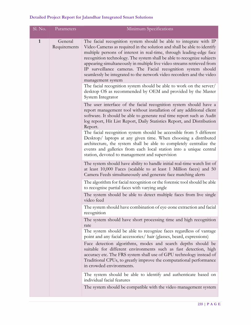
Detailed Project Report for Jalandhar Integrated Smart Solutions
235 | P A G E
Sl. No. Parameters Minimum Specifications
1 General Requirements
The facial recognition system should be able to integrate with IP Video Cameras as required in the solution and shall be able to identify multiple persons of interest in real-time, through leading-edge face recognition technology. The system shall be able to recognize subjects appearing simultaneously in multiple live video streams retrieved from IP surveillance cameras. The Facial recognition system should seamlessly be integrated to the network video recorders and the video management system
The facial recognition system should be able to work on the server/ desktop OS as recommended by OEM and provided by the Master System Integrator
The user interface of the facial recognition system should have a report management tool without installation of any additional client software. It should be able to generate real time report such as Audit log report, Hit List Report, Daily Statistics Report, and Distribution Report.
The facial recognition system should be accessible from 5 different Desktop/ laptops at any given time. When choosing a distributed architecture, the system shall be able to completely centralize the events and galleries from each local station into a unique central station, devoted to management and supervision
The system should have ability to handle initial real-time watch list of at least 10,000 Faces (scalable to at least 1 Million faces) and 50 Camera Feeds simultaneously and generate face matching alerts
The algorithm for facial recognition or the forensic tool should be able to recognise partial faces with varying angle
The system should be able to detect multiple faces from live single video feed
The system should have combination of eye-zone extraction and facial recognition
The system should have short processing time and high recognition rate
The system should be able to recognize faces regardless of vantage point and any facial accessories/ hair (glasses, beard, expressions)
Face detection algorithms, modes and search depths should be suitable for different environments such as fast detection, high accuracy etc. The FRS system shall use of GPU technology instead of Traditional CPUs, to greatly improve the computational performance in crowded environments.
The system should be able to identify and authenticate based on individual facial features
The system should be compatible with the video management system
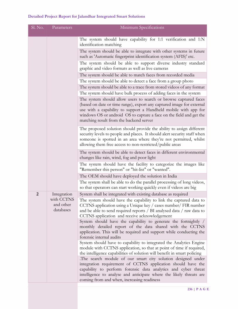
Detailed Project Report for Jalandhar Integrated Smart Solutions
236 | P A G E
Sl. No. Parameters Minimum Specifications
The system should have capability for 1:1 verification and 1:N identification matching
The system should be able to integrate with other systems in future such as 'Automatic fingerprint identification system (AFIS)' etc.
The system should be able to support diverse industry standard graphic and video formats as well as live cameras
The system should be able to match faces from recorded media
The system should be able to detect a face from a group photo
The system should be able to a trace from stored videos of any format
The system should have bulk process of adding faces in the system
The system should allow users to search or browse captured faces (based on date or time range), export any captured image for external use with a capability to support a Handheld mobile with app for windows OS or android OS to capture a face on the field and get the matching result from the backend server
The proposed solution should provide the ability to assign different security levels to people and places. It should alert security staff when someone is spotted in an area where they’re not permitted, whilst allowing them free access to non-restricted/public areas
The system should be able to detect faces in different environmental changes like rain, wind, fog and poor light
The system should have the facility to categorize the images like "Remember this person" or "hit-list" or "wanted".
The OEM should have deployed the solution in India
The system shall be able to do the parallel processing of long videos, so that operators can start working quickly even if videos are big
2 Integration with CCTNS
and other databases
System shall be integrated with existing database as required
The system should have the capability to link the captured data to CCTNS application using a Unique key / cases number/ FIR number and be able to send required reports / BI analysed data / raw data to CCTNS application and receive acknowledgement
System should have the capability to generate the fortnightly / monthly detailed report of the data shared with the CCTNS application. This will be required and support while conducting the forensic internal audits
System should have to capability to integrated the Analytics Engine module with CCTNS application, so that at point of time if required, the intelligence capabilities of solution will benefit in smart policing
.The search module of our smart city solution designed under integration requirement of CCTNS application should have the capability to perform forensic data analytics and cyber threat intelligence to analyse and anticipate where the likely threats are coming from and when, increasing readiness

Detailed Project Report for Jalandhar Integrated Smart Solutions
237 | P A G E
Sl. No. Parameters Minimum Specifications
3 Case Management
The system shall be able to create cases corresponding to investigation operations
The system shall be able to manage videos and photos within a certain case
The system shall be usable by numerous investigators or video analysts together on the same case, working in parallel on in series, so that big cases could be processed efficiently
The system shall make the findings of one operators immediately and easily available to all other operators, to increase video / photo case analysis efficiency and speed
The system shall give a holistic view of all videos and photos of a case, so that operators get a full picture of the case (and not limited view, item by item)
The system shall include purge capability at the case level or at the video level
The system shall include the ability to backup and restore cases
The system shall make it easy to navigate across the whole set of video and photo of the case for people and vehicle
4 Video and Photo
Management
The system shall be able to manage video flow from IP cameras as RTSP streams
The system shall be able to record live video flows or to rely on external video flow recording (e.g. in a DVR), to offer the same functionality on past live video than on recorded videos
The system shall be able to manage videos up to 4K resolution, with no limitation in length or frame rate
The system shall be able to ingest and manage any photo in JPEG or PNG format, of any size
5 Data Management
The system shall be able to manage context metadata on video and images (geographical location, image acquisition conditions, time stamp).
The system shall allow edit, detect, and extract content metadata from videos and photos
The System should allow Navigation of videos based on timestamp
The system shall be able to detect and extract content metadata from the live and recorded video and photos of a certain case: for person's face, body and vehicle's license plate
System's users shall be able to control which metadata is extracted from the videos and photos of a case, individually at the video or photo level

Detailed Project Report for Jalandhar Integrated Smart Solutions
238 | P A G E
Sl. No. Parameters Minimum Specifications
With face metadata, the system shall be able to detect and record a best image of the face, the gender and age range of the corresponding person, and generate a feature vector making it possible to use face for biometric comparison
With person body metadata, the system shall be able to detect and record a best image of the person, the color of the upper body and lower body of the person
With license plate meta data, the system shall be able to detect and record a best image of the license plate, and the OCR corresponding to this license plate
User friendly interface for browsing videos and photos such as filtering, album view and support adding descriptive text and sharing
Meta data shall provide filtering like face, body, license plate, age, gender, upper body, lower body, colour, moving object etc.
The system shall provide functions for colour marking in images included in reports and blurring out areas for privacy reasons
The system shall provide operator with fast viewing tools on video: video display at variable speeds
The system shall provide operators with most efficient abstract of individual videos: concatenation of sequence which are likely to be where wrong doing or suspect activity can be seen, restricted area of the video., face, people seen by their body, either in the full video or on a restricted area of the video, license plates
The system shall display where specific types of detection have been found, as heat maps at any time or at a selected timeframe
The system shall make it easy for operators to determine if multiple different people have been together / are related
6 Alerts The system shall be able to search by face, in real time, in live video flows, people recorded in watch list and raise alerts when someone recorded in a watch list has been seen. Alerts review shall be available to operators
The system shall offer parameters to select which faces detected in real time will be matched against the watch lists, in order to minimize false alerts
The system shall include an advanced alert presentation user interface, both for watch list alerts and tracking alerts, by which the operator shall be able to see where the alert happened (on a map), the context of the alert, the person causing the alert and the person recorded in a watch list or tracked.

Detailed Project Report for Jalandhar Integrated Smart Solutions
239 | P A G E
Sl. No. Parameters Minimum Specifications
The system shall include a personalizable alert presentation user interface, where it is possible depending on operator right to select which kind of alerts are received and to tune the threshold used for the generation of alerts, at the camera and watch list levels.
The system shall be capable of sending out the alerts as notifications, so that external systems and users could also see the alerts
The system shall include a query capability to search detections within the whole case by textual description
7 Search The query results shall be easily displayed as a list of suitable respondents
The query results shall be easily displayed as a map showing where the suitable respondents were seen
The system shall display the path of respondents on a map
The system shall make it easy for operator to visualize detect objects trajectories
The query results shall be easily displayed as a graph where suitable respondent will be linked to each other if they appear on the same video or photo (i.e. together) in a configurable time interval
8 Watch list Management
The system shall come with watch lists management capabilities, where watch list will contain person data represented by face
The system shall be able to attach watch lists to cases, so that upon detection of a face in a case, the face would be compared to all the watch lists attached to the case, and the corresponding comparison results could be shown to operators
The system shall automatically associate a face detection to a watch list element when the comparison yields a score that is high enough
A watch list search review interface should be proposed to operators, so that they could easily determine who in the available watch lists was seen in the videos and photos of a certain case
Watch list management shall include deduplication of watch list content, so that it could be known if a given person already belongs to a watch list
Watch list management shall include the ability to add a face detected in a case into a give watch list in one click
The system shall be able to import face images in its watch lists by batch
9 Security The system shall manage access control of operators
The system shall manage security (access restriction) on watch lists
The system shall manage security (access restriction) on cases
The system shall manage security (ability to use) on available functions
The system shall manage users preferences (please specify what is managed)

Detailed Project Report for Jalandhar Integrated Smart Solutions
240 | P A G E
Sl. No. Parameters Minimum Specifications
10 Reports The system shall include the ability to produce reports easily usable for investigators and in court
The system shall come with a set of management reports
The system shall come with dashboards showing the activity of the system
7.4.4. Geographic Locations for Installation of CCTV
The 154 locations identified by Jalandhar Police for installation of CCTV City Surveillance system
are mapped as below
Sr Location Long_DMS Lat_DMS Long_DD Lat_DD
1 Issa Nagar 75° 32' 24.454" E
31° 22' 46.455" N
75.54012601 31.37957081
2 Verka Milk Plant 75° 33' 35.532" E
31° 21' 47.952" N
75.55987 31.36332
3 Sanjay Gandhi Nehar Pulli
75° 34' 6.728" E
31° 21' 36.313" N
75.56853569 31.36008708
4 Hardev Nagar 75° 33' 17.028" E
31° 20' 9.636" N
75.55473 31.33601
5 Gaji Gulla Chowk 75° 34' 21.288" E
31° 20' 29.400" N
75.57258 31.3415

Detailed Project Report for Jalandhar Integrated Smart Solutions
241 | P A G E
Sr Location Long_DMS Lat_DMS Long_DD Lat_DD
6 Y-Point Bhagat Singh Colony
75° 33' 44.646" E
31° 21' 38.076" N
75.56240175 31.36057679
7 Sehnai Palace Chowk
75° 33' 50.718" E
31° 19' 23.379" N
75.56408821 31.32316082
8 Sabji Mandi Chowk 75° 34' 10.373" E
31° 20' 2.512" N
75.56954799 31.33403119
9 Gulab Devi Road 75° 33' 49.328" E
31° 20' 18.620" N
75.56370218 31.33850557
10 OBC Kapurthla Chowk
75° 33' 44.413" E
31° 20' 0.891" N
75.56233696 31.3335809
11 Shakti Nagar Park 75° 34' 6.120" E
31° 19' 41.012" N
75.56836657 31.32805881
12 Adarsh Nagar Near Gita Mandir
75° 33' 49.376" E
31° 19' 38.486" N
75.56371562 31.32735714
13 ShaheedUdam Singh Nagar
75° 34' 11.720" E
31° 19' 33.126" N
75.56992225 31.32586844
14 Shetla Mata Mandir Chowk
75° 34' 31.889" E
31° 20' 10.500" N
75.57552462 31.3362499
15 Doaba Chowk 75° 35' 6.994" E
31° 20' 40.771" N
75.58527624 31.34465874
16 Bhaghat Singh Chowk
75° 34' 58.263" E
31° 19' 54.208" N
75.58285087 31.33172455
17 Damoria Pull under Bridge
75° 34' 8.569" E
31° 20' 6.993" N
75.56904704 31.33527589
18 Damoria Pull over Bridge
75° 35' 9.863" E
31° 20' 7.308" N
75.58607309 31.33536344
19 Adda Tanda Road Phatak
75° 34' 46.891" E
31° 20' 21.967" N
75.57969196 31.33943537
20 Adda Hoshiarpur Chowk
75° 34' 51.300" E
31° 20' 11.305" N
75.58091678 31.33647353
21 Phagwara Gate Market
75° 34' 56.263" E
31° 19' 48.808" N
75.58229531 31.33022455
22 Park Corporation Office
75° 34' 50.563" E
31° 19' 42.308" N
75.58071198 31.32841899
23 Milap Chowk 75° 34' 49.020" E
31° 19' 40.200" N
75.58028333 31.32783333
24 Sikka Chowk 75° 34' 16.320" E
31° 19' 28.200" N
75.5712 31.3245
25 Circuit House 75° 34' 44.760" E
31° 19' 19.380" N
75.5791 31.32205
26 TV Center 75° 34' 7.980" E
31° 19' 14.340" N
75.56888333 31.32065

Detailed Project Report for Jalandhar Integrated Smart Solutions
242 | P A G E
Sr Location Long_DMS Lat_DMS Long_DD Lat_DD
27 Civil Hospital Jalandhar
75° 34' 28.164" E
31° 19' 37.214" N
75.57448993 31.32700389
28 Desh Bhagat Yadgar Hall Near BMC Chowk
75° 34' 1.440" E
31° 19' 7.860" N
75.56706667 31.31885
29 Ali Baba Mobile Center Turn towards SUS Nagar
75° 34' 24.306" E
31° 19' 22.746" N
75.57341845 31.32298503
30 SBI Main Branch Civil Line Jal
75° 34' 44.640" E
31° 19' 20.340" N
75.57906667 31.32231667
31 Park Near Loins Club Lajpat Nagar Jal
75° 34' 31.440" E
31° 19' 7.320" N
75.5754 31.3187
32 Shakti Nagar Park 75° 34' 1.920" E
31° 19' 30.180" N
75.5672 31.32505
33 Rock Garden 75° 34' 9.540" E
31° 19' 33.960" N
75.56931667 31.3261
34 Gujral Nagar Market 75° 34' 59.820" E
31° 19' 21.540" N
75.58328333 31.32265
35 Gakhal Puli (City Ceiling )
75° 31' 40.192" E
31° 18' 46.651" N
75.52783104 31.31295851
36 Kot Sadiq Nehar Puli Kala Sangia Road
75° 31' 54.083" E
31° 18' 9.785" N
75.53168981 31.30271797
37 Babrik Chowk 75° 33' 20.295" E
31° 19' 12.982" N
75.5556374 31.32027283
38 Kari Chowk Basti Danishmanda
75° 32' 39.966" E
31° 19' 10.076" N
75.54443509 31.3194656
39 Adda Basti Shiekh 75° 33' 22.155" E
31° 19' 4.076" N
75.55615417 31.31779894
40 Peer Chowk Jhandiya Wala
75° 33' 42.460" E
31° 19' 36.234" N
75.56179453 31.32673178
41 Y-Point Evening College Basti Nau
75° 33' 31.283" E
31° 19' 30.725" N
75.55868981 31.3252013
42 T-Point St Soldier College Basti Danishmanda
75° 32' 13.078" E
31° 19' 1.299" N
75.53696609 31.31702748
43 Guru Nanak Colony Wala Chowk
75° 32' 37.489" E
31° 18' 33.208" N
75.54374696 31.3092244
44 Ghas Mandi Chowk 75° 33' 3.986" E
31° 18' 41.326" N
75.55110726 31.31147951
45 Dusehra Ground Kala Sanghia Road
75° 33' 0.572" E
31° 18' 46.340" N
75.55015899 31.31287214
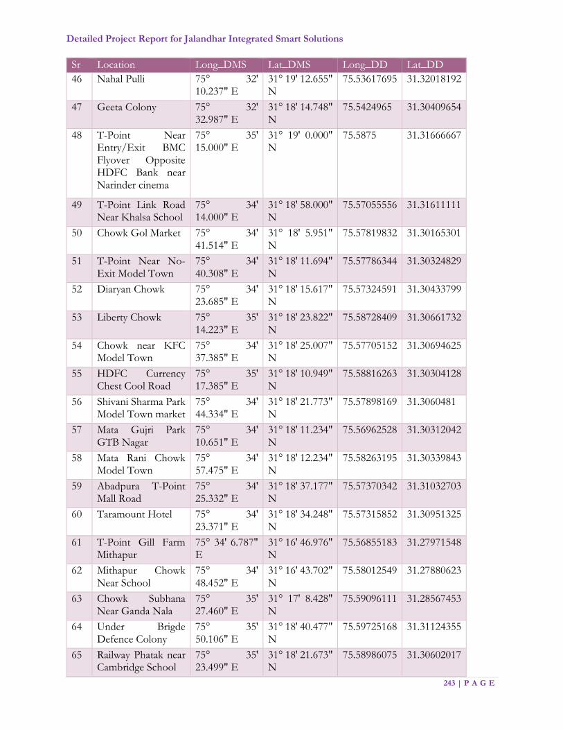
Detailed Project Report for Jalandhar Integrated Smart Solutions
243 | P A G E
Sr Location Long_DMS Lat_DMS Long_DD Lat_DD
46 Nahal Pulli 75° 32' 10.237" E
31° 19' 12.655" N
75.53617695 31.32018192
47 Geeta Colony 75° 32' 32.987" E
31° 18' 14.748" N
75.5424965 31.30409654
48 T-Point Near Entry/Exit BMC Flyover Opposite HDFC Bank near Narinder cinema
75° 35' 15.000" E
31° 19' 0.000" N
75.5875 31.31666667
49 T-Point Link Road Near Khalsa School
75° 34' 14.000" E
31° 18' 58.000" N
75.57055556 31.31611111
50 Chowk Gol Market 75° 34' 41.514" E
31° 18' 5.951" N
75.57819832 31.30165301
51 T-Point Near No-Exit Model Town
75° 34' 40.308" E
31° 18' 11.694" N
75.57786344 31.30324829
52 Diaryan Chowk 75° 34' 23.685" E
31° 18' 15.617" N
75.57324591 31.30433799
53 Liberty Chowk 75° 35' 14.223" E
31° 18' 23.822" N
75.58728409 31.30661732
54 Chowk near KFC Model Town
75° 34' 37.385" E
31° 18' 25.007" N
75.57705152 31.30694625
55 HDFC Currency Chest Cool Road
75° 35' 17.385" E
31° 18' 10.949" N
75.58816263 31.30304128
56 Shivani Sharma Park Model Town market
75° 34' 44.334" E
31° 18' 21.773" N
75.57898169 31.3060481
57 Mata Gujri Park GTB Nagar
75° 34' 10.651" E
31° 18' 11.234" N
75.56962528 31.30312042
58 Mata Rani Chowk Model Town
75° 34' 57.475" E
31° 18' 12.234" N
75.58263195 31.30339843
59 Abadpura T-Point Mall Road
75° 34' 25.332" E
31° 18' 37.177" N
75.57370342 31.31032703
60 Taramount Hotel 75° 34' 23.371" E
31° 18' 34.248" N
75.57315852 31.30951325
61 T-Point Gill Farm Mithapur
75° 34' 6.787" E
31° 16' 46.976" N
75.56855183 31.27971548
62 Mithapur Chowk Near School
75° 34' 48.452" E
31° 16' 43.702" N
75.58012549 31.27880623
63 Chowk Subhana Near Ganda Nala
75° 35' 27.460" E
31° 17' 8.428" N
75.59096111 31.28567453
64 Under Brigde Defence Colony
75° 35' 50.106" E
31° 18' 40.477" N
75.59725168 31.31124355
65 Railway Phatak near Cambridge School
75° 35' 23.499" E
31° 18' 21.673" N
75.58986075 31.30602017
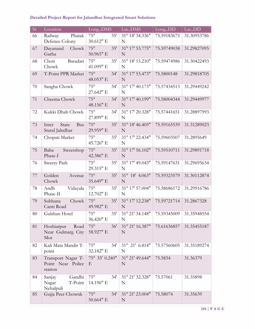
Detailed Project Report for Jalandhar Integrated Smart Solutions
244 | P A G E
Sr Location Long_DMS Lat_DMS Long_DD Lat_DD
66 Railway Phatak Defence Colony
75° 35' 30.612" E
31° 18' 34.336" N
75.59183675 31.30953786
67 Dayanand Chowk Garha
75° 35' 50.965" E
31° 17' 53.775" N
75.59749038 31.29827095
68 Choti Baradari Chowk
75° 35' 41.099" E
31° 18' 15.210" N
75.59474986 31.30422493
69 T-Point PPR Market 75° 34' 48.053" E
31° 17' 53.473" N
75.5800148 31.29818705
70 Sangha Chowk 75° 34' 27.642" E
31° 17' 40.173" N
75.57434513 31.29449242
71 Cheema Chowk 75° 34' 48.156" E
31° 17' 40.199" N
75.58004344 31.29449977
72 Kukki Dhab Chowk 75° 34' 27.899" E
31° 17' 20.328" N
75.57441651 31.28897993
73 Inter State Bus Stand Jalndhar
75° 35' 29.959" E
31° 18' 46.405" N
75.59165539 31.31289023
74 Chopati Market 75° 35' 45.726" E
31° 17' 22.434" N
75.59603507 31.2895649
75 Baba Sweetshop Phase-I
75° 35' 42.386" E
31° 17' 56.102" N
75.59510711 31.29891718
76 Sweety Park 75° 35' 29.315" E
31° 17' 49.043" N
75.59147631 31.29695634
77 Golden Avenue Chowk
75° 35' 35.649" E
31° 18' 4.063" N
75.59323579 31.30112874
78 Andh Vidayala Phase-II
75° 35' 12.702" E
31° 17' 57.004" N
75.58686172 31.29916786
79 Subhana Chowk Cantt Road
75° 35' 49.982" E
31° 17' 12.238" N
75.59721714 31.2867328
80 Gulshan Hotel 75° 35' 36.420" E
31° 21' 34.148" N
75.59345009 31.35948554
81 Hoshiarpur Road Near Gulmarg City Mor
75° 36' 58.927" E
31° 21' 16.387" N
75.61636857 31.35455187
82 Kali Mata Mandir T-point
75° 34' 32.182" E
31° 21' 6.814" N
75.57560605 31.35189274
83 Transport Nagar T-Point Near Police station
75° 35' 0.240" E
31° 21' 49.644" N
75.5834 31.36379
84 Sanjay Gandhi Nagar T-Point Nehalpuli
75° 34' 14.196" E
31° 21' 32.328" N
75.57061 31.35898
85 Gujja Peer Chownk 75° 34' 50.664" E
31° 21' 23.004" N
75.58074 31.35639

Detailed Project Report for Jalandhar Integrated Smart Solutions
245 | P A G E
Sr Location Long_DMS Lat_DMS Long_DD Lat_DD
86 Dargah Peer Baba Nimboo Shah ji
75° 35' 50.352" E
31° 20' 46.968" N
75.59732 31.34638
87 Aman Nagar Road near GP Tower T-Point
75° 35' 10.619" E
31° 21' 23.533" N
75.58628292 31.35653692
88 Aman Nagar Morh Near KMV college
75° 35' 21.156" E
31° 21' 7.560" N
75.58921 31.3521
89 T-Point Angoora Dia Bela Santokhpura
75° 35' 30.228" E
31° 20' 55.248" N
75.59173 31.34868
90 Nimbuawali Gali 75° 35' 31.308" E
31° 20' 50.640" N
75.59203 31.3474
91 Sodal Chowk 75° 34' 30.864" E
31° 20' 54.852" N
75.57524 31.34857
92 Devi Talab Mandir 75° 34' 57.901" E
31° 20' 36.995" N
75.58275026 31.34360964
93 Thapra Bagichi 75° 34' 35.220" E
31° 20' 57.516" N
75.57645 31.34931
94 KalishNagar Near Mandir
75° 34' 50.484" E
31° 20' 56.832" N
75.58069 31.34912
95 Court Road Chowk 75° 35' 18.780" E
31° 19' 6.180" N
75.58855 31.31838333
96 Madan Flour Mill Chowk
75° 35' 21.360" E
31° 19' 36.000" N
75.58926667 31.32666667
97 Kamal Palace Chowk
75° 35' 9.060" E
31° 19' 11.760" N
75.58585 31.31993333
98 Alaska Chowk 75° 35' 28.800" E
31° 19' 27.540" N
75.59133333 31.32431667
99 Railway Crossing Guru Nanak Pura West
75° 36' 33.600" E
31° 19' 5.340" N
75.60933333 31.31815
100 Railway Crossing Sant Nagar Fatak
75° 36' 2.460" E
31° 19' 19.140" N
75.60068333 31.32198333
101 Railway Crossing Ladowali Road
75° 35' 56.940" E
31° 19' 2.640" N
75.59915 31.3174
102 Front of Police Line 75° 35' 37.440" E
31° 18' 51.180" N
75.59373333 31.31421667
103 Puda Ground opp DC Office
75° 35' 36.385" E
31° 19' 10.911" N
75.59344041 31.31969752
104 Bank of Badodha Railway Road Currency Chest
75° 35' 23.580" E
31° 19' 39.240" N
75.58988333 31.32756667

Detailed Project Report for Jalandhar Integrated Smart Solutions
246 | P A G E
Sr Location Long_DMS Lat_DMS Long_DD Lat_DD
105 SBI Shastari Market Currency Chest
75° 35' 41.160" E
31° 19' 26.460" N
75.59476667 31.32401667
106 SBI Mandi Fanttan Ganjh Railway Road Currency Chest
75° 35' 23.396" E
31° 19' 38.805" N
75.58983215 31.3274459
107 Neta Ji Park Master Tara Singh Nagar
75° 35' 18.720" E
31° 19' 17.220" N
75.58853333 31.32145
108 Rly Stn Gate No 1 75° 35' 28.300" E
31° 19' 50.200" N
75.59119444 31.33061111
109 Rly Stn Gate No 2 75° 35' 24.800" E
31° 19' 50.200" N
75.59022222 31.33061111
110 Rly Stn Gate No 3 75° 35' 23.000" E
31° 19' 54.600" N
75.58972222 31.33183333
111 Nangal Shama Chowk
75° 38' 1.320" E
31° 19' 31.140" N
75.6337 31.32531667
112 Suchi Pind Pulli 75° 37' 33.420" E
31° 20' 33.000" N
75.62595 31.3425
113 Dhillwan Chowk 75° 37' 56.131" E
31° 19' 12.557" N
75.63225849 31.32015475
114 Batha Road 75° 36' 25.020" E
31° 19' 47.760" N
75.60695 31.32993333
115 Dakoha Railway Crossing Choke Point
75° 38' 13.740" E
31° 18' 16.380" N
75.63715 31.30455
116 Chugitti Railway Crossing Choke Point
75° 37' 1.080" E
31° 19' 24.300" N
75.61696667 31.32341667
117 Partap Palace Chowk
75° 37' 14.460" E
31° 19' 31.260" N
75.62068333 31.32535
118 Under Brij Chugitti 75° 36' 53.340" E
31° 19' 20.340" N
75.61481667 31.32231667
119 Guru Nanak Dev University Campus Ladowali Road
75° 37' 25.320" E
31° 20' 1.080" N
75.6237 31.33363333
120 Rama Mandi Main Market
75° 37' 45.060" E
31° 18' 39.840" N
75.62918333 31.31106667
121 Guru Nanak Pura Main Market
75° 36' 41.040" E
31° 19' 13.920" N
75.6114 31.32053333
122 Sainik Vihar 75° 38' 13.020" E
31° 18' 52.200" N
75.63695 31.3145
123 Kamal Vihar 75° 36' 13.020" E
31° 19' 44.340" N
75.60361667 31.32898333

Detailed Project Report for Jalandhar Integrated Smart Solutions
247 | P A G E
Sr Location Long_DMS Lat_DMS Long_DD Lat_DD
124 Wadala Chowk 75° 33' 27.213" E
31° 17' 39.582" N
75.55755923 31.29432846
125 Rejant Park Avtar Nagar
75° 33' 57.000" E
31° 19' 14.940" N
75.56583333 31.32081667
126 Sethi Battery T-Point Model House
75° 33' 25.980" E
31° 18' 35.880" N
75.55721667 31.30996667
127 Udey Nagar Chowk 75° 33' 3.617" E
31° 17' 55.200" N
75.55100477 31.29866677
128 Chara Mandi Butta Mandi
75° 33' 44.022" E
31° 18' 7.064" N
75.56222846 31.30196235
129 Mata Rani Chowk 75° 33' 45.626" E
31° 18' 39.834" N
75.56267388 31.31106494
130 Park near Gurdwara Singh Saba Model House Road
75° 33' 36.497" E
31° 18' 30.921" N
75.56013813 31.30858927
131 Wadala Road Phase-II
75° 33' 1.130" E
31° 17' 39.431" N
75.55031395 31.29428632
132 T-Point Nakhawala Bagh
75° 32' 48.324" E
31° 17' 54.932" N
75.54675665 31.29859215
133 Waryana Morh 75° 31' 36.112" E
31° 20' 29.091" N
75.5266977 31.34141425
134 T-Point Leather Complex
75° 31' 41.685" E
31° 19' 49.411" N
75.52824591 31.33039199
135 T-Point Shashtri Nagar
75° 33' 13.471" E
31° 19' 33.957" N
75.55374198 31.32609921
136 T-Point Mithu Basti(Near Patwar Khana)
75° 33' 4.000" E
31° 19' 59.000" N
75.55111111 31.33305556
137 Pull Nehar KPT Road
75° 32' 59.463" E
31° 20' 9.893" N
75.54985071 31.33608132
138 Pull Nehar S.B.L.S Nagar
75° 33' 11.739" E
31° 20' 39.838" N
75.55326077 31.34439955
139 Jagjiwan Ram chowk 75° 32' 49.000" E
31° 19' 19.000" N
75.54694444 31.32194444
140 Sher Singh Pull Nehar
75° 32' 24.684" E
31° 19' 28.398" N
75.54019011 31.32455502
141 Basti Peer Dad Chowk(Lakkar Wala Pull)
75° 32' 41.336" E
31° 19' 47.692" N
75.54481564 31.32991434
142 Leather Complex Chowk( Ganda Nala)
75° 31' 38.000" E
31° 19' 46.000" N
75.52722222 31.32944444
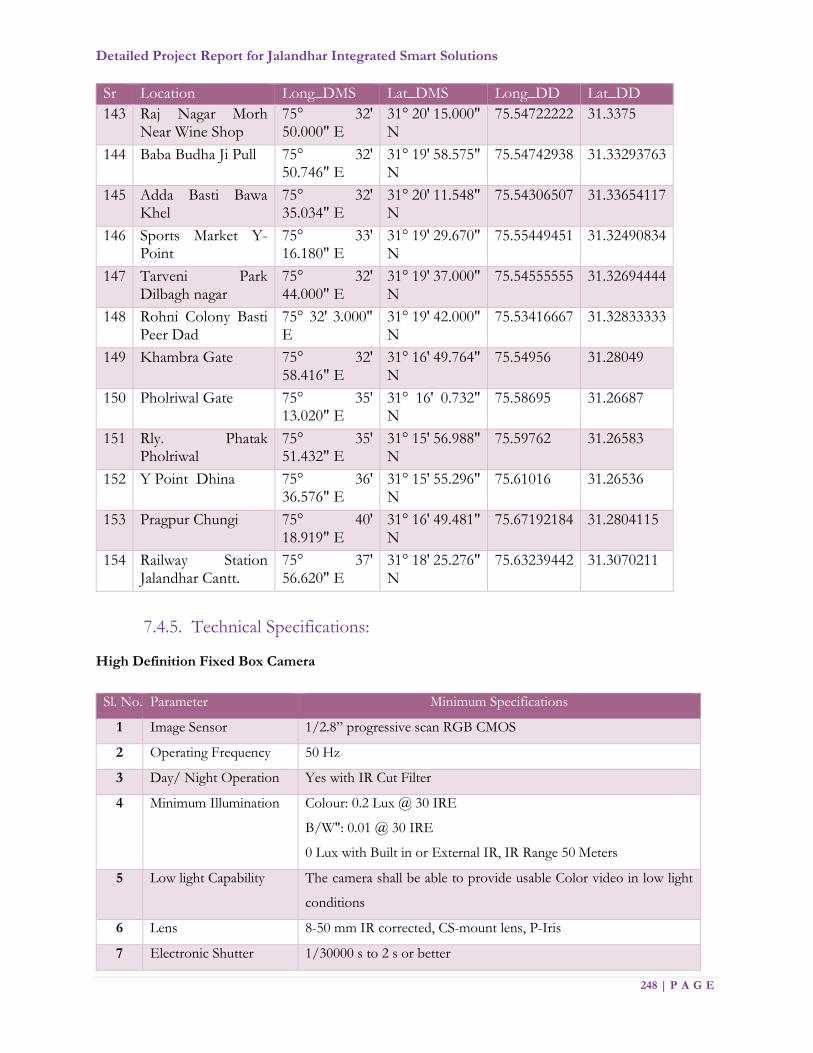
Detailed Project Report for Jalandhar Integrated Smart Solutions
248 | P A G E
Sr Location Long_DMS Lat_DMS Long_DD Lat_DD
143 Raj Nagar Morh Near Wine Shop
75° 32' 50.000" E
31° 20' 15.000" N
75.54722222 31.3375
144 Baba Budha Ji Pull 75° 32' 50.746" E
31° 19' 58.575" N
75.54742938 31.33293763
145 Adda Basti Bawa Khel
75° 32' 35.034" E
31° 20' 11.548" N
75.54306507 31.33654117
146 Sports Market Y-Point
75° 33' 16.180" E
31° 19' 29.670" N
75.55449451 31.32490834
147 Tarveni Park Dilbagh nagar
75° 32' 44.000" E
31° 19' 37.000" N
75.54555555 31.32694444
148 Rohni Colony Basti Peer Dad
75° 32' 3.000" E
31° 19' 42.000" N
75.53416667 31.32833333
149 Khambra Gate 75° 32' 58.416" E
31° 16' 49.764" N
75.54956 31.28049
150 Pholriwal Gate 75° 35' 13.020" E
31° 16' 0.732" N
75.58695 31.26687
151 Rly. Phatak Pholriwal
75° 35' 51.432" E
31° 15' 56.988" N
75.59762 31.26583
152 Y Point Dhina 75° 36' 36.576" E
31° 15' 55.296" N
75.61016 31.26536
153 Pragpur Chungi 75° 40' 18.919" E
31° 16' 49.481" N
75.67192184 31.2804115
154 Railway Station Jalandhar Cantt.
75° 37' 56.620" E
31° 18' 25.276" N
75.63239442 31.3070211
7.4.5. Technical Specifications:
High Definition Fixed Box Camera
Sl. No. Parameter Minimum Specifications
1 Image Sensor 1/2.8” progressive scan RGB CMOS
2 Operating Frequency 50 Hz
3 Day/ Night Operation Yes with IR Cut Filter
4 Minimum Illumination Colour: 0.2 Lux @ 30 IRE
B/W": 0.01 @ 30 IRE
0 Lux with Built in or External IR, IR Range 50 Meters
5 Low light Capability The camera shall be able to provide usable Color video in low light
conditions
6 Lens 8-50 mm IR corrected, CS-mount lens, P-Iris
7 Electronic Shutter 1/30000 s to 2 s or better

Detailed Project Report for Jalandhar Integrated Smart Solutions
249 | P A G E
8 Image Resolution 1920 x 1080, 1280 x 720, 800 x 450, 480 x 270, 320 x 240
9 Compression H.265 in High and Base profile, MPEG4, MJPEG
10 Frame Rate and Bit Rate 25 FPS at all resolutions with Controllable Bit Rate/ Bandwidth and
Frame Rate
11 Video Streams The camera shall be able to setup and stream out minimum three (3)
stream profiles. Each stream profile can have its own compression,
resolution, frame rate and quality independently
12 Motion Detection Yes built in with multiple configurable areas in the video stream
13 Pan Tilt Zoom Digital PTZ
14 Frame Rate and Bit Rate Up to 50 fps at all resolutions
15 Electronic Exposure &
Control
Automatic/ Manual
16 Wide Dynamic Range 120 dB or better
17 Backlight Compensation Required
18 Privacy Masks Minimum 20 configurable 3D zones
19 Connectors 1 Input & 1 Output for Alarm Interface
20 Event Triggers Intelligent video, Edge Storage event, External Input, Audio Level,
Motion Detection, Day/Night Mode, Network, Time scheduled, 3rd
Party Analytics, Manual Trigger, Alarm Input Trigger
21 Event Actions File upload: FTP, HTTP, network share and email Notification:
email, HTTP and TCP
PTZ function, Edge Storage/ Storage, Pre & Post Alarm Recording,
Actions configurable by web interface, External Output activation
22 Edge Storage Built in SD card slot with support up to 128 GB with Class 10 speed
23 Built in installation aids Focus assistant, Pixel counter, Remote back focus
24 Storage The Cameras shall have the feature to directly record the videos/
images onto NAS/SAN without any Software or integration
25 Protocols IPv4/v6, HTTP , HTTPS b, SSL/TLS b, QoS Layer 3 DiffServ, FTP
, CIFS/SMB, SMTP, Bonjour, UPnP™,SNMPv1/v2c/v3 (MIB - II),
DNS, DynDNS, NTP, RTSP, RTP,TCP, UDP,IGMP,RTCP,ICMP,
DHCP,ARP, SOCKS
26 Text Overlay Date & time, and a customer-specific text, camera name, graphical
image etc.
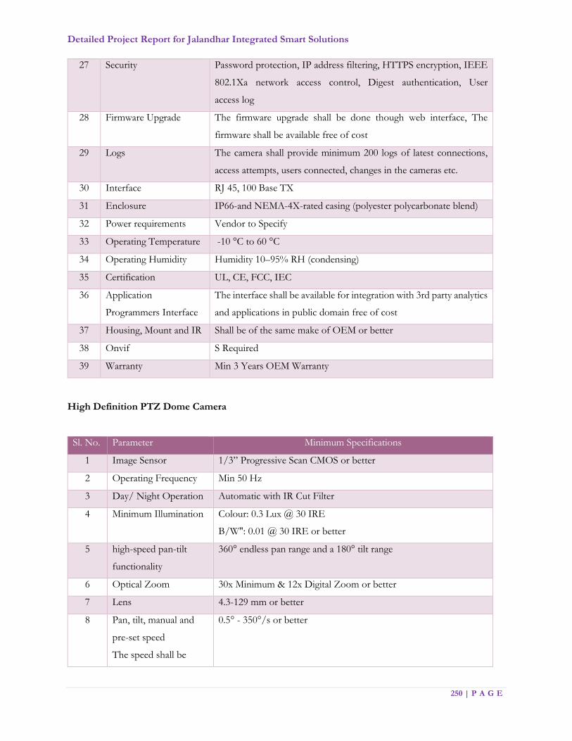
Detailed Project Report for Jalandhar Integrated Smart Solutions
250 | P A G E
27 Security Password protection, IP address filtering, HTTPS encryption, IEEE
802.1Xa network access control, Digest authentication, User
access log
28 Firmware Upgrade The firmware upgrade shall be done though web interface, The
firmware shall be available free of cost
29 Logs The camera shall provide minimum 200 logs of latest connections,
access attempts, users connected, changes in the cameras etc.
30 Interface RJ 45, 100 Base TX
31 Enclosure IP66-and NEMA-4X-rated casing (polyester polycarbonate blend)
32 Power requirements Vendor to Specify
33 Operating Temperature -10 °C to 60 °C
34 Operating Humidity Humidity 10–95% RH (condensing)
35 Certification UL, CE, FCC, IEC
36 Application
Programmers Interface
The interface shall be available for integration with 3rd party analytics
and applications in public domain free of cost
37 Housing, Mount and IR Shall be of the same make of OEM or better
38 Onvif S Required
39 Warranty Min 3 Years OEM Warranty
High Definition PTZ Dome Camera
Sl. No. Parameter Minimum Specifications
1 Image Sensor 1/3” Progressive Scan CMOS or better
2 Operating Frequency Min 50 Hz
3 Day/ Night Operation Automatic with IR Cut Filter
4 Minimum Illumination Colour: 0.3 Lux @ 30 IRE
B/W": 0.01 @ 30 IRE or better
5 high-speed pan-tilt
functionality
360° endless pan range and a 180° tilt range
6 Optical Zoom 30x Minimum & 12x Digital Zoom or better
7 Lens 4.3-129 mm or better
8 Pan, tilt, manual and
pre-set speed
The speed shall be
0.5° - 350°/s or better
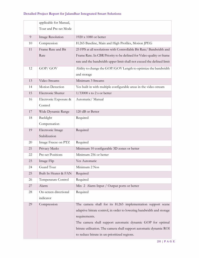
Detailed Project Report for Jalandhar Integrated Smart Solutions
251 | P A G E
applicable for Manual,
Tour and Pre-set Mode
9 Image Resolution 1920 x 1080 or better
10 Compression H.265 Baseline, Main and High Profiles, Motion JPEG
11 Frame Rate and Bit
Rate
25 FPS at all resolutions with Controllable Bit Rate/ Bandwidth and
Frame Rate. In CBR Priority to be defined for Video quality or frame
rate and the bandwidth upper limit shall not exceed the defined limit
12 GOP/ GOV Ability to change the GOP/GOV Length to optimize the bandwidth
and storage
13 Video Streams Minimum 3 Streams
14 Motion Detection Yes built in with multiple configurable areas in the video stream
15 Electronic Shutter 1/33000 s to 2 s or better
16 Electronic Exposure &
Control
Automatic/ Manual
17 Wide Dynamic Range 120 dB or Better
18 Backlight
Compensation
Required
19 Electronic Image
Stabilization
Required
20 Image Freeze on PTZ Required
21 Privacy Masks Minimum 10 configurable 3D zones or better
22 Pre-set Positions Minimum 256 or better
23 Image Flip Yes Automatic
24 Guard Tour Minimum 2 Nos
25 Built In Heater & FAN Required
26 Temperature Control Required
27 Alarm Min 2 Alarm Input / Output ports or better
28 On-screen directional
indicator
Required
29 Compression The camera shall for its H.265 implementation support scene
adaptive bitrate control, in order to lowering bandwidth and storage
requirements.
The camera shall support automatic dynamic GOP for optimal
bitrate utilisation. The camera shall support automatic dynamic ROI
to reduce bitrate in un-prioritized regions.

Detailed Project Report for Jalandhar Integrated Smart Solutions
252 | P A G E
30 Event Triggers The camera shall be able to send and received trigger directly from
any other camera without interface of VMS.
Live Stream Accessed, Motion Detection, Shock
Detection, Audio Detection, Network, Temperature, Manual
Trigger, Virtual Inputs, Alarm Inputs, PTZ: Error, Moving, Pre-set
Reached, Ready, Storage Disruption, Storage Recording, System
Ready, User schedule
31 Event Actions File upload via FTP, SFTP, HTTP and email
Notification via email, HTTP and TCP
Pre- and post-alarm video buffering, External output activation,
PTZ pre-set, guard tour, Video recording to edge storage, Day/night
mode, Overlay text
32 Pixel Counter Built in
33 Edge Storage Built in SD card slot with support up to 128 GB with Class 10 speed
34 Storage The Cameras shall have the feature to directly record the videos/
images onto storage without any Software
35 Protocols At least IP, HTTP, HTTPS, SSL/TLS, TCP, ICMP,
SNMPv1/v2c/v3 (MIB-II), RTSP, RTP, UDP, IGMP, RTCP,
SMTP, FTP, DHCP, UPnP, ARP, DNS, DynDNS, SOCKS, NTP,
CIFS/SMB. IPv4 & IPv6 and Bonjour
36 Text Overlay Date & time, and a customer-specific text, camera name, graphical
image etc.
37 Security Password protection, IP address filtering, HTTPS encryption,
IEEE 802.1Xa network access control, Digest authentication, User
access log
38 Firmware Upgrade The firmware upgrade shall be done though web interface, The
firmware shall be available free of cost
39 Logs The camera shall provide Minimum 200 logs of latest connections,
access attempts, users connected, changes in the cameras etc.
40 Interface RJ 45, 100 Base TX
41 Enclosure Die Cast Aluminium, IK10 rated, IP66 rated, polycarbonate clear
dome and sunshield, PVC free complying to WEEE Standards
42 Mount Wall / Pole Mount

Detailed Project Report for Jalandhar Integrated Smart Solutions
253 | P A G E
43 Power requirements Power over Ethernet (POE/PoE+) IEEE 802.3at Type 2 Class 4,
max. 24 W, Typical 9W; 24 V DC max. 30 W
24 V AC, max. 40 VA or better
44 Operating Temperature -10 °C to 60 °C or better
45 Operating Humidity 10–95% RH (condensing) or better
46 Certification UL, CE, FCC
47 Embedded
Applications
The camera shall provide a platform allowing the upload of third
party applications into the camera
48 Application
Programmers Interface
The interface shall be available for integration with 3rd party
analytics and applications in public domain free of cost
49 Onvif S required
50 Warranty Min 3 Years OEM warranty
Multi Sensor 360° Panoramic View PTZ Camera
Sl. No. Parameter Minimum Specifications
1 General Requirements The camera should be manufacturer's official product line designed
for commercial / industrial 24x7x365 use. The camera and camera
firmware should be designed and developed by same OEM.
2 General Requirements The camera should be based upon standard components and
proven technology using open and published protocols
3 Image Sensor Minimum 4 x 3MP, 1/3.2" CMOS - (Total) 12MP or better
4 Lens Specs F2.0, Day/night (infrared cut filter); Options of 2.8/4/8/12/16
MM wide angle Lens
5 Video Resolution 1920 X 1080 or better
6 Minimum illumination Colour: 0.6 lux or better, Monochrome: 0.05 Lux or better with IR
7 Video Compression H.265, Motion JPEG
8 Frame Rate 25fps or better
9 Wide Dynamic Range 100 dB or better
10 Camera Angle
Adjustment
Pan: - ±90°
Tilt: - 28° - 92°
Rotate: - ±90°
11 Network Interface 100 Base-T ports
12 Power Supply POE/POE+ IEE 802.3af compliant
13 Industry Standards ONVIF Compliant

Detailed Project Report for Jalandhar Integrated Smart Solutions
254 | P A G E
14 Certifications UL, FCC
15 Enclosure Type IP66; IK 10
16 Operating
Temperature
-10° C to 60° C or better
17 Operating Humidity 0 - 90%
18 Supported Network
protocols
Minimum of the following RTSP, RTP/TCP, RTP/UDP, HTTP,
DHCP protocols to be supported
19 Support The system should not be an end of life / end of service product.
Bullet Camera
Sl. No Parameter Minimum Specifications
1 Image Sensor 1/3” progressive scan RGB CMOS or better
2 Operating Frequency 50 Hz
3 Day/ Night Operation Yes with IR Cut Filter
4 Minimum Illumination Color: 0.3 Lux @ 30 IRE F1.4; 0 Lux with IR
5 Mechanical Pan Tilt Adjustment Pan: ± 135°, Tilt: 0°– 90°
6 Lens 3 - 10 mm, IR corrected, P-Iris, Megapixel Lens with remote zoom and focus
7 Electronic Shutter 1 s to 1/25000 s or better
8 Image Resolution 1920 x 1080 or better
9 Compression H.265 compression or equivalent with 3 Mbps or lower speed at 1920 X 1080 @ 30 FPS per stream and MJPEG
10 Frame Rate and Bit Rate Up to 50 FPS at all resolutions with Controllable Bit Rate/ Bandwidth and Frame Rate. In CBR Priority to be defined for Video quality or frame rate and the bandwidth upper limit shall not exceed the defined limit
11 Image reproduction The camera shall have the capability to produce Colored video images in low light conditions
12 Video Streams The camera shall be able to setup and stream out minimum three (3) stream profiles. Each stream profile can have its own compression, resolution, frame rate and quality independently
13 Motion Detection Yes built in with multiple configurable areas in the video stream
14 Image Configuration The Camera shall be able to Include or Exclude any area of any size/ dimension within the scene in order to Eliminate False alarm and also optimize the bandwidth and storage
15 Pan Tilt Zoom Digital PTZ
16 Wide Dynamic Range 120 dB or better

Detailed Project Report for Jalandhar Integrated Smart Solutions
255 | P A G E
17 Backlight Compensation Required
18 IR 30 Meter (Built in or External) Optimized IR with adjustable intensity and angle
19 Alarm Connectors 1 Input & 1 Output for Alarm Interface
20 Event Triggers Live Stream Accessed, Motion Detection, Day/Night Mode, Network, Temperature, , Camera Tampering, Edge Storage Disruption, Video Analytics, Manual Trigger
21 Event Actions FTP, HTTP, network share, email Notification: email, PTZ function, Edge Storage/ Storage, Pre & Post Alarm Recording, Actions configurable by web interface, WDR Mode, External Output Trigger, Text Overlay
22 Edge Storage SD Card Slot with 64GB Support Class 10 speed
23 Protocols IPv4/v6, HTTP, HTTPS, SSL/TLS, QoS Layer 3 DiffServ, FTP, CIFS/SMB, SMTP, Bonjour, UPnP, SNMPv1/v2c/v3 (MIB - II), DNS, DynDNS, NTP, RTSP, RTP,TCP, UDP, IGMP,RTCP,ICMP,DHCP,ARP,SOCKS, SSH
24 Text Overlay Date & time, and a customer-specific text, camera name, graphical image etc.
25 Security Password protection, IP address filtering, HTTPS encryption, IEEE 802.1X network access control, Digest authentication, User access log
26 Firmware Upgrade The firmware upgrade shall be done though web interface, The firmware shall be available free of cost
27 Interface RJ 45, 100 Base TX
28 Memory 512 MB RAM, 256 MB Flash or better
29 Enclosure IP66 rated and NEMA-4X-rated casing Polycarbonate/Aluminium, IK 08
30 Power requirements PE IEEE 802.3af / POE+ IEEE 902.3at compliant
31 Operating Temperature -20 °C to 50 °C
32 Operating Humidity Humidity 10–95% RH (condensing)
33 Certification UL, CE, FCC, IEC,
34 Application Programmers Interface The interface shall be available for integration with 3rd party analytics and applications in public domain
35 Embedded Applications The camera shall provide a platform allowing the upload of third party applications into the camera
36 Mount Wall Mount/ Pole Mount
37 Onvif S Required
38 Warranty 5 Years OEM warranty
39 Security Detection of camera tampering and Detection of Motion should be possible using either camera or VMS
40 Functional Self-cleaning / anti-dust / hydro-phobic coating features
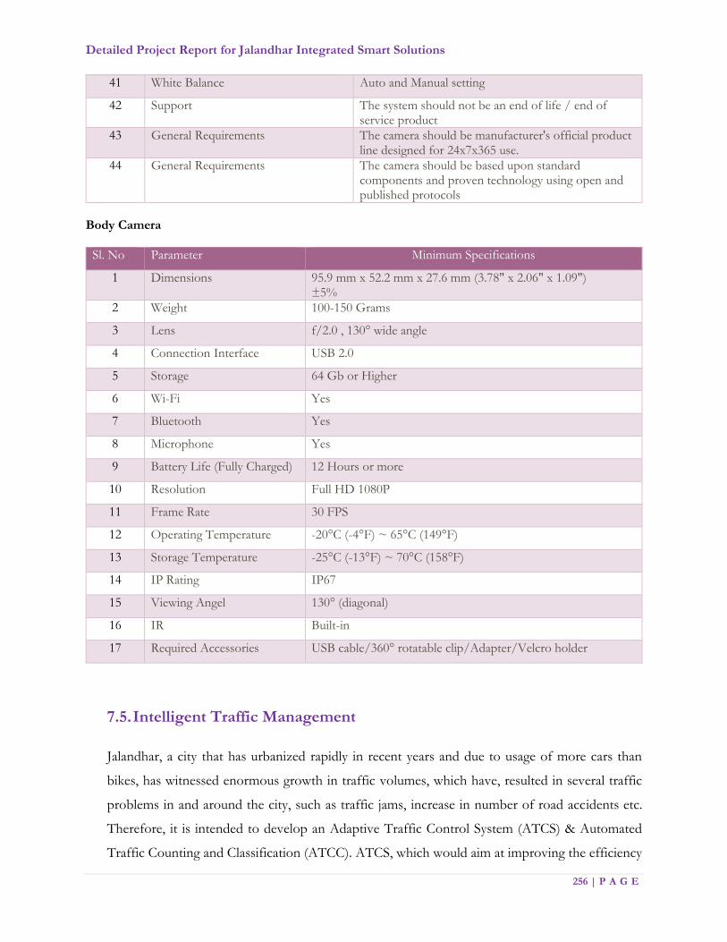
Detailed Project Report for Jalandhar Integrated Smart Solutions
256 | P A G E
41 White Balance Auto and Manual setting
42 Support The system should not be an end of life / end of service product
43 General Requirements The camera should be manufacturer's official product line designed for 24x7x365 use.
44 General Requirements The camera should be based upon standard components and proven technology using open and published protocols
Body Camera
Sl. No Parameter Minimum Specifications
1 Dimensions 95.9 mm x 52.2 mm x 27.6 mm (3.78" x 2.06" x 1.09") ±5%
2 Weight 100-150 Grams
3 Lens f/2.0 , 130° wide angle
4 Connection Interface USB 2.0
5 Storage 64 Gb or Higher
6 Wi-Fi Yes
7 Bluetooth Yes
8 Microphone Yes
9 Battery Life (Fully Charged) 12 Hours or more
10 Resolution Full HD 1080P
11 Frame Rate 30 FPS
12 Operating Temperature -20°C (-4°F) ~ 65°C (149°F)
13 Storage Temperature -25°C (-13°F) ~ 70°C (158°F)
14 IP Rating IP67
15 Viewing Angel 130° (diagonal)
16 IR Built-in
17 Required Accessories USB cable/360° rotatable clip/Adapter/Velcro holder
7.5. Intelligent Traffic Management
Jalandhar, a city that has urbanized rapidly in recent years and due to usage of more cars than
bikes, has witnessed enormous growth in traffic volumes, which have, resulted in several traffic
problems in and around the city, such as traffic jams, increase in number of road accidents etc.
Therefore, it is intended to develop an Adaptive Traffic Control System (ATCS) & Automated
Traffic Counting and Classification (ATCC). ATCS, which would aim at improving the efficiency
Detailed Project Report for Jalandhar Integrated Smart Solutions
257 | P A G E
and effectiveness of the traffic on arterial and VIP roads in Jalandhar roads and ATCC (Automated
Traffic Counting and Classification), shall be implemented at the traffic junctions, which are
standalone.
To realize the benefits of ATMS & ATCC, it is pertinent to adopt an approach that includes
technology based regulation, intervention, information and enforcement system to improve the
mobility, discipline and safety on Jalandhar roads. Therefore, ATMS & ATCC is envisaged with
multiple applications, including Adaptive Traffic Control System and Automated Traffic Counting
and Classification (ATCC), Red Light Violation Detection (RLVD) systems, Automatic Number
Plate Recognition (ANPR), Speed Violation Detection Systems (SVDS), Pelican Signals, Variable
Message System (VaMS), eChallans, Traffic Surveillance Cameras & Pelican signals amongst
others which will ensure that the intended outcomes have been accomplished.
ATMS & ATCC integrates various sub systems (such as CCTV, vehicle detection, communication,
Local processing units, variable message signs etc.) in a coherent single interface that provides real
time data on status of traffic and predicts traffic conditions for more efficient planning and
operations. Thus, a system such as ATMS & ATCC shall aim to help police and security agencies
to take proactive/ reactive measures and ensure safe & smooth environment on road. Wherever
the current Jalandhar City CCTV Surveillance System cameras can be utilized for the traffic
management, necessary integration is expected.
The technical solution should cater to the following challenges:
1. Traffic congestion and huge waiting time
2. No right of way to emergency vehicles like ambulance, police etc.
3. VIP movement clearance
4. Lack of information on prominent & frequent traffic congestions both location wise and
time wise
5. Absence of street level public information & communication channel
6. Absence of central control mechanism to monitor & regulate the Jalandhar City traffic
flow
Specifically, MSI should make sure that below mentioned technical capabilities must be link with
Integrated City Management Control Centre:
a) Installation of Traffic Light Aspects with all accessories at the selected junctions.
b) Adaptive Traffic Control System (ATCS)
c) Automated Traffic Counting and Classification (ATCC)

Detailed Project Report for Jalandhar Integrated Smart Solutions
258 | P A G E
d) Red Light Violation Detection (RLVD) system
e) Automatic Number Plate Recognition(ANPR)
f) Speed violation detection (SVDS)
g) Pelican signals
h) Emergency call box
i) E-Challan System
j) Traffic Surveillance
k) Real Time Traffic Analytics Platform
l) PAS system
m) Variable Message Sign boards
n) Integration with Vahan and Sarathi databases
o) Integration with GIS Map
p) Additional components like timer etc. shall be added as required based on the detailed
study
q) Repair of existing signals should be considered as part of BID DOCUMENT (like timer
were observed)
r) Existing functional signals for the implementation of ATCS and ATCC shall be verified
and should be considered to extend the life of signal
s) All traffic elements should be branded to showcase as smart city elements
The scope of work shall include but will not be limited to the following broad areas.
1. Scoping and Feasibility Study: Conduct a detailed scoping study and develop a
comprehensive project plan, including:
Feasibility study for finalization of detailed technical architecture and project
plan
Development of traffic management plans for individual signal controls and
groups of signal controllers along with pre-planned intervention strategies for
special scenarios
Site surveys to identify need for junction improvement, junction signage, lane
markings and other necessary site infrastructure
Site Clearance obligations & other relevant permissions.
2. Field Equipment: Design, Supply, Installation and Commissioning of following
field equipment envisaged in ATMS:
Detailed Project Report for Jalandhar Integrated Smart Solutions
259 | P A G E
Adaptive Traffic Control System at Signalized traffic junctions
Variable Message Signs (detailed out in subsequent section)
Red Light Violation Detection system
E-Challan System
Emergency call box etc. as mentioned above
3. Network Connectivity: Provision of Network Connectivity for ATMS
equipment/solution
Developing necessary connectivity for ATMS
Integrating live data streams from other traffic information systems such as real
time public transport bus location data, parking information systems, etc.
4. Hardware and Software Infrastructure: Design, Supply, Installation and
Commissioning of IT Infrastructure at JICCC and DC: This shall consist of
following activities:
Basic Site preparation services
IT Infrastructure including server, storage, other required hardware, application
portfolio and licences
Centralized platform for traffic data analytics and signal optimization
JICCC infrastructure including operator workstations, video walls, IP phones,
joystick controller etc.
Establishment of LAN and WAN connectivity at JICCC and DC
Application Integration Services & SMS gateway
5. Capacity Building: Preparation of operational manuals, training documents and
capacity building support, including:
Preparation and implementation of the Information security policy, including
policies on backup and redundancy plan
Preparation of revised traffic signal control plans, alternate signal control plans,
KPIs for performance monitoring of transport network, dashboards for MIS
Training of the city authorities and Traffic Police personnel on
operationalization of the system
Acceptance testing
System and configuration Documents, User Documents
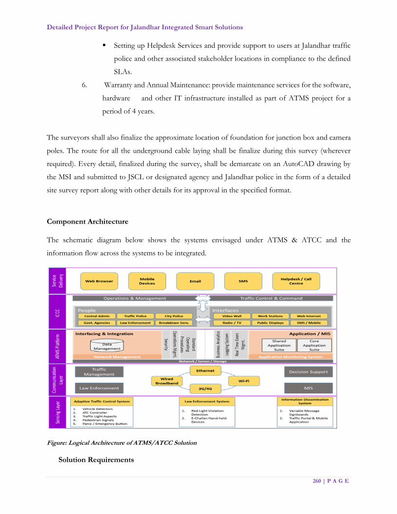
Detailed Project Report for Jalandhar Integrated Smart Solutions
260 | P A G E
Setting up Helpdesk Services and provide support to users at Jalandhar traffic
police and other associated stakeholder locations in compliance to the defined
SLAs.
6. Warranty and Annual Maintenance: provide maintenance services for the software,
hardware and other IT infrastructure installed as part of ATMS project for a
period of 4 years.
The surveyors shall also finalize the approximate location of foundation for junction box and camera
poles. The route for all the underground cable laying shall be finalize during this survey (wherever
required). Every detail, finalized during the survey, shall be demarcate on an AutoCAD drawing by
the MSI and submitted to JSCL or designated agency and Jalandhar police in the form of a detailed
site survey report along with other details for its approval in the specified format.
Component Architecture
The schematic diagram below shows the systems envisaged under ATMS & ATCC and the
information flow across the systems to be integrated.
Figure: Logical Architecture of ATMS/ATCC Solution
Solution Requirements
Detailed Project Report for Jalandhar Integrated Smart Solutions
261 | P A G E
The MSI shall be responsible for Supply, Installation, Implementation and Operation &
Maintenance of Jalandhar Surveillance System for a period of Four Years from the date of Go-
Live. The indicative requirements are broadly categorized into following:
Sl. No. Parameters Minimum Specifications
1 Min Signalling
System
Infrastructure at
field locations
1. Public Announcement System (PAS), Emergency call box
2. Supply, Install, Implement and Maintenance of IP based
cameras with IR
a. Fixed box Cameras
b. PTZ Cameras
c. RLVD
d. ANPR
e. SVDS
Additional features for the camera :
Camera to support Adaptive Traffic Control System (ATCS)
Camera to support ANPR
Camera to support RLVD
Camera that support Analytics
Sensor/optical analytics required for (ATCS and ATCC)
Note: There is pole and traffic light aspects installation required
for traffic signals and cameras as required. The cameras should
be installed using appropriate fittings. Installation configuration
and maintenance of poles & required power, backup, network
connectivity and any other additional hardware and software
fittings is in the scope of MSI.
Data Retention Period: 30 days
The detailed location wise camera distribution will be describe
in bid document
2 Network
Infrastructure
1. Between camera & aggregation point – Field location
2. Between aggregation points & Data center
3. Between Data Center & JICCC
4. Between Data Center & viewing/monitoring center and
satellite control center

Detailed Project Report for Jalandhar Integrated Smart Solutions
262 | P A G E
5. It is envisaged that the MSI will coordinate and take services
of the existing Network Providers in Jalandhar like BSNL,
Airtel, Railtel etc. However, a tri-party Agreement among JSCL,
MSI & the Network Service Providers would be sign in order to
meet networking requirements as defined within Service Level
Agreement.
3 Data Center 1. Supply & installation of all the requisite ICT Infrastructure
including server, storage, network components and peripherals
to handle 100% load along with provisioning for redundancy
2. Supply & installation of all the requisite Non IT infrastructure
like furniture, AC, and interior work etc. excluding the civil work
at the space, which will be provided by JSCL
4 Integrated
Command
Control Center
1. Supply & installation of all the IT & Non IT infrastructure
such as the Video Wall, Workstation, AC, and interior work,
etc. excluding civil work at the space provided by JSCL
5 Applications at
JICCC
1. Video Management System (VMS)
2. Video Analytics (VA)
3. Red Light Violation Detection (RLVD) System
4. Automatic Number Plate Recognition (ANPR) System
5. Integration with RTO applications like Vahan / Parivahan to
extract details like Owner Name, Address, Age, Engine
Number, Chassis Number, vehicle Registration Date,, vehicle
Registration City, Type, Model, City ,State
6.Analyse and implement User specific requirement
implementation
7. ATCS, ATCC Implementation
6 Capacity
Building
MSI is to provide all Technical & Functional training/capacity
building/handholding for the designated
officials/staff/personnel on a continuous basis
Detailed Project Report for Jalandhar Integrated Smart Solutions
263 | P A G E
7.5.1. Key Performance Indicators
The KPIs for the project are as follows:
a. Improve Journey Time Reliability: Improve reliability in journey times between various
locations, so that citizens can experience an enhanced quality of road based transportation,
through improving sustainability and efficiency in operation of the road network
b. Increased Traffic Signal Efficiency: Reduction in traffic delays, optimized cycle times
at intersection to regulate and maintain free flow of traffic to enhance the efficiency of the
transport infrastructure.
c. Increase Operational Efficiency: Jalandhar Traffic Police intends to spend more time
on the public facing functions. Thus, Information technology solutions should help in
reducing the repetitive paperwork/records and making the back-office functions more
efficient.
d. Improve Customer Services: The traffic services to the public can be improve through
the user-friendly presentation of the various traffic information in real time through
sharing of all relevant data feeds for public consumption.
e. Safety Improvement: The real time traffic monitoring and intelligent traffic systems can
prevent accidents by recognizing and thus responding to the potentially dangerous
situation in advance. It shall also provide safety for pedestrians.
f. Higher Productivity: Achieving improvement in the productivity, logistics and other
economic activities by obtaining the precise-real time information on transport due to the
availability of data on traffic flow in key areas of the city.
g. Real Time Information, Event Tracking & Response, and Fast Access to Stored
Information: The real time information at the JICCC shall enable the operator to take
necessary actions based on the type of information. Sending an emergency vehicle to the
spot, arranging alternate route to VIP convoys, diverting the traffic to different routes are
some of the actions that can be taken based on the Real Time Information. It shall be
possible to track a particular event using the cameras installed at the traffic junction. A
vehicle, violating the traffic could be tracked and penalized at the next traffic junction
based on the number plate.
h. Creating awareness for public: Through sign boards, awareness on road traffic rules
and safe driving precautions shall be imparted to road users.

Detailed Project Report for Jalandhar Integrated Smart Solutions
264 | P A G E
i. Enforcement: Effective enforcement of traffic violation, checking and monitoring shall
reduce the traffic related offences of Red Light violations
j. Create a platform for sharing traffic information across the city: There is a critical
need to create a platform for sharing traffic related information among traffic police and
citizens in order to increase the effectiveness of Adaptive Traffic Control System.
k. Planning & Operations: Intelligent Signal planning & operational aspects shall be
handling at command center using City Operations Platform/IoT Platform (COP).
l. Integration: Intelligent Signalling aspects shall be enabled by integration with City
Operations Platform and GIS Maps.
7.5.2. Components of Intelligent Signalling
1. Adaptive Traffic Control System (ATCS) – Video based Vehicle detection (integrated signals
forming a green tunnel), Signal controller, Traffic light aspects, poles, power supply
provisioning and related accessories and associated civil work including cabling for successful
operation of the system
2. Automated Traffic Counting and Classification (ATCC) – Video based Vehicle detection
(Independent signal control), Signal controller, Traffic light aspects, poles, power supply
provisioning and related accessories and associated civil work including cabling for successful
operation of the system
3. Red Light Violation Detection (RLVD) System along with related accessories and required
mounting infrastructure including civil work for successful operation of the system
4. Automatic Number Plate Recognition (ANPR) system along with related accessories and
required mounting infrastructure including civil work for successful operation.
5. Speed violation detection system with automated e-challan
6. Pelican Signals
7. Traffic Surveillance Cameras along with related accessories and required mounting
infrastructure including civil work for successful operation of the system
8. Public Address Systems for dissemination of critical information.
9. Emergency call box for use of citizens to notify JICCC / public authorities regarding
emergent situations.
10. Video Management Server & Video Analytics server
11. E-Challans Systems
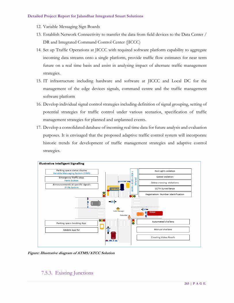
Detailed Project Report for Jalandhar Integrated Smart Solutions
265 | P A G E
12. Variable Messaging Sign Boards
13. Establish Network Connectivity to transfer the data from field devices to the Data Center /
DR and Integrated Command Control Center (JICCC)
14. Set up Traffic Operations at JICCC with required software platform capability to aggregate
incoming data streams onto a single platform, provide traffic flow estimates for near term
future on a real time basis and assist in analysing impact of alternate traffic management
strategies.
15. IT infrastructure including hardware and software at JICCC and Local DC for the
management of the edge devices signals, command centre and the traffic management
software platform
16. Develop individual signal control strategies including definition of signal grouping, setting of
potential strategies for traffic control under various scenarios, specification of traffic
management strategies for planned and unplanned events.
17. Develop a consolidated database of incoming real time data for future analysis and evaluation
purposes. It is envisaged that the proposed adaptive traffic control system will incorporate
historic trends for development of traffic management strategies and adaptive control
strategies.
Figure: Illustrative diagram of ATMS/ATCC Solution
7.5.3. Existing Junctions
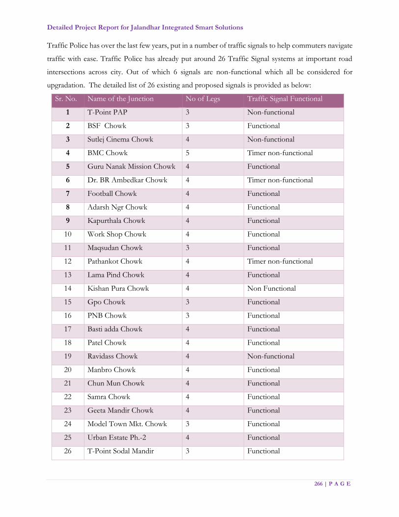
Detailed Project Report for Jalandhar Integrated Smart Solutions
266 | P A G E
Traffic Police has over the last few years, put in a number of traffic signals to help commuters navigate
traffic with ease. Traffic Police has already put around 26 Traffic Signal systems at important road
intersections across city. Out of which 6 signals are non-functional which all be considered for
upgradation. The detailed list of 26 existing and proposed signals is provided as below:
Sr. No. Name of the Junction No of Legs Traffic Signal Functional
1 T-Point PAP 3 Non-functional
2 BSF Chowk 3 Functional
3 Sutlej Cinema Chowk 4 Non-functional
4 BMC Chowk 5 Timer non-functional
5 Guru Nanak Mission Chowk 4 Functional
6 Dr. BR Ambedkar Chowk 4 Timer non-functional
7 Football Chowk 4 Functional
8 Adarsh Ngr Chowk 4 Functional
9 Kapurthala Chowk 4 Functional
10 Work Shop Chowk 4 Functional
11 Maqsudan Chowk 3 Functional
12 Pathankot Chowk 4 Timer non-functional
13 Lama Pind Chowk 4 Functional
14 Kishan Pura Chowk 4 Non Functional
15 Gpo Chowk 3 Functional
16 PNB Chowk 3 Functional
17 Basti adda Chowk 4 Functional
18 Patel Chowk 4 Functional
19 Ravidass Chowk 4 Non-functional
20 Manbro Chowk 4 Functional
21 Chun Mun Chowk 4 Functional
22 Samra Chowk 4 Functional
23 Geeta Mandir Chowk 4 Functional
24 Model Town Mkt. Chowk 3 Functional
25 Urban Estate Ph.-2 4 Functional
26 T-Point Sodal Mandir 3 Functional

Detailed Project Report for Jalandhar Integrated Smart Solutions
267 | P A G E
Arms Number of Junctions
3 7
4 18
5 1
The following figure illustrates the junctions which, are functional, non-functional signals, arterial road
and VIP road for which ATCS shall be installed. ATCC shall be install at three locations at an identified
junction during the detailed survey by MSI.
Figure – ATCS road, VIP road, Functional and Non-functional junctions
7.5.4. Infrastructure at ITMS
This component covers planning & implementation of the Signalling System comprising cameras
and other field equipment at locations identified by JSCL. However, actual placement of pole &
number of cameras at each location, type of cameras, fixation of height & angle for the cameras
to ensure maximum coverage should be undertaken in consultation with Jalandhar Police / Traffic
Police.
Detailed Project Report for Jalandhar Integrated Smart Solutions
268 | P A G E
A detailed survey shall be conduct, by the MSI along with a team from JSCL and Jalandhar Police,
at each of the strategic locations. This survey shall finalize the position of all field equipment’s and
the orientation/ field of view of the cameras. Appropriate field of view snapshot shall be taken by
a handheld camera for future reference at the time of survey. The surveyors shall also finalize the
approximate location of foundation for junction box and poles. The route for all the underground
cable laying shall be finalized during this survey (wherever required). Every detail, finalized during
the survey, shall be demarcated on an AutoCAD drawing by the MSI and submitted to JSCL in
the form of a detailed site survey report along with other details for its approval.
The system shall provide inter-operability of hardware, operating system, software, networking,
printing, database connectivity, reporting, and communication protocols. MSI shall prepare the
Detailed Report for field level requirements such as Cameras (types & numbers), Camera
Mounting requirements, Power Requirements, Connectivity Requirements etc. for perusal of
JSCL. Indicative list of the field level hardware to be provide by MSI is as follows:
1. Cameras with IR illuminators (Fixed Box, PTZ, ANPR, RLVD cameras etc.)
2. IR illuminators - External
3. Local processing unit for ANPR / RLVD cameras
4. Switches
5. Outdoor Cabinets
6. Pole for cameras / Mast
7. Outdoor Junction box
8. UPS
9. Networking and power cables, solar panels and other related infrastructure
Supply & Installation of Camera Infrastructure
Based on detailed field survey as mentioned above, MSI shall be required to supply, install and
commission the surveillance and monitoring systems at the identified locations and thereafter
undertake necessary work towards its testing. MSI shall use industry-leading practices during the
implementation phase w.r.t positioning and mounting the cameras, poles and junction boxes.
Detailed Project Report for Jalandhar Integrated Smart Solutions
269 | P A G E
Some of the checkpoints that need to be adhered to by the MSI while installing / commissioning
cameras are as follows:
1. Ensure that surveillance and monitoring objective is met while positioning the camera
such that the required field of view is being captured as finalized in field survey
2. Ensure that camera is protect from the field challenges of weather, physical damage and
theft.
3. Make proper adjustments to have the best possible image / video captured.
4. Ensure that the pole is well place for vibration resistance adhering to the road safety
norms.
5. Deployment of Collusion preventive barriers around the junction box & pole foundation
in case it is install in collision prone place.
6. Deployment of Appropriate branding or colour coding (Police/JSCL Branding) of poles
and junction boxes, to warn mischief mongers against tampering with the equipment at
the junction.
Installation of Poles/Cantilevers/Gantry if required
1. The MSI shall ensure that all installations are done as per satisfaction of the JSCL.
2. For installation of CCTV Cameras, PTZ Cameras, Public Address System, etc. MSI shall
provide appropriate poles & cantilevers and any supporting equipment.
3. MSI shall be required to supply, install, configure and integrate surveillance cameras at the
identified locations and thereafter undertake necessary work towards their commissioning.
4. MSI shall ensure that the poles erected to mount cameras are good, both qualitatively and
aesthetically
5. MSI shall use the industry leading practices while positioning and mounting the cameras
and ensure that the pole / mast implementation is vibration resistant. Arrangements for
bird scare spikes on top of camera shall be made to prevent birds from sitting on top of
camera box.
6. The poles shall be install with base plate, pole door, pole distributor block and cover.
7. Base frames and screws shall be deliver along with poles and installed by the MSI.
8. In case the cameras need to be install beside or above the signal heads, suitable stainless
steel extensions for poles need to be provide and installed by the MSI so that there is clear
line of sight.

Detailed Project Report for Jalandhar Integrated Smart Solutions
270 | P A G E
9. MSI shall be responsible to undertake required structural analysis regarding the regulated
load conditions and considering the respective wind load while installing the poles /
cantilevers for cameras
10. MSI shall provide structural calculations and drawings for the approval of JSCL. The
design shall match with common design standards as applicable under the jurisdiction of
JSCL.
11. MSI shall coordinate with concerned authorities / municipalities for installation.
12. Poles and cabinet shall be so design such that all elements of the field equipment could be
easily install and removed.
13. MSI shall ensure that physical look of the installation area returns to neat & tidy conditions
after installation of poles, cantilevers etc. The placement shall be design keeping in mind
the normal flow of vehicular traffic and pedestrian movement is not disturbed.
UPS for field locations
1. UPS shall serve as a backup for commercially available utility power at the intersections
and shall ensure no-break functioning of all field components at each intersection in event
of failure of utility power supply
2. MSI shall carry out a study and identify locations to provide UPS backup, depending upon
power situation across Jalandhar City, to meet the camera and other field equipment’s
uptime requirements.
3. MSI shall install UPS at the identified intersections in secure, tamper-proof housing in
corrosion resistant cabinets.
4. MSI shall ensure that the UPS is suitably protect against storms, power surges and
lightning.
5. MSI shall provide UPS for efficient heat dissipation without air conditioning. It shall be
able to withstand temperatures prevalent in Jalandhar throughout the year.

Detailed Project Report for Jalandhar Integrated Smart Solutions
271 | P A G E
Outdoor Cabinets / Junction Boxes
1. Each intersection shall be fitted with outdoor cabinets dimensioned to host all equipment
necessary to operate enforcement systems and traffic surveillance systems that will be
defined in the bid document
2. The cabinets provided shall be plug and play
3. MSI shall reserve additional room in the intersection controller cabinet to accommodate
the future system requirements
4. The size of outdoor cabinet / Junction Boxes shall be sufficient to house all the system
components, which may be install at the intersection or nearby. Boxes shall be dustproof
and impermeable to splash-water (IP65 or better). They shall be suitable for Jalandhar’s
environmental conditions. They shall have separate lockable doors for:
a. Power cabinet: This cabinet shall house the electricity meter, online UPS system
and the redundant power supply system
b. Control cabinet: This cabinet shall house the controllers for all the field
components at that particular location e.g. ANPR, PTZ, RLVD, Fixed box
cameras etc.
5. Internal cabinet cabling shall be designed for an easy connection and disconnection of the
equipment and power
6. The cabinets shall be of robust construction and shall include 3-point security-locking
mechanisms to prevent unauthorized access to the field equipment
7. Temperature and Humidity Control: All enclosure compartments shall be equipped with
a natural convection air circulation system via provision of air circulation filters that shall
not require maintenance and shall allow free circulation of air inside the enclosures to
prevent overheating as well as the build-up and effects of humidity and heat, without
permitting the entry of elements that might endanger system operation

Detailed Project Report for Jalandhar Integrated Smart Solutions
272 | P A G E
8. MSI shall ensure that all the hardware is placed inside the junction boxes that could
withstand temperatures prevalent in Jalandhar throughout the year
Civil and Electrical Works
1. MSI shall be responsible for carrying out all the civil & Electrical work required for setting
up all the field components of the system including:
a. Preparation of concrete foundation for MS-Poles & cantilevers
b. Laying of GI Pipes (B Class) complete with GI fitting
c. Hard soil deep digging and backfilling after cabling
d. Soft soil deep digging and backfilling after cabling
e. Chambers with metal cover at every junction box, pole and at road crossings
f. Concrete foundation from the Ground for outdoor racks
2. MSI shall provide power to the cameras through the aggregation point. Since this
component has dependency on approval from local authorities, it is recommended that
MSI plans this requirement well in advance & submits the application to the concerned
electricity distribution agency with requisite fees, as applicable.
3. MSI shall carry out all the electrical work required for powering all the components of the
system
4. Electrical installation and wiring shall conform to the electrical codes of India
5. MSI shall make provisions for providing electricity to the cameras (ANPR, PTZ, and
Fixed) via Junction Box, housing the UPS/SMPS power supply, with minimum backup
that will be defined in bid document
6. For the wired Box cameras, MSI shall provision for drawing power through PoE/ PoE+
(Power over Ethernet), while PTZ cameras shall be powered through dedicated power
cable laid separately along with STP/SFTP cable
7. Registration of electrical connections at all field sites shall be done in the name JSCL
8. MSI shall house the electricity meters inside the power cabinet as mentioned in the
controller Cabinet section as above.

Detailed Project Report for Jalandhar Integrated Smart Solutions
273 | P A G E
Earthing and Lightning Proof Measures
1. MSI shall comply with the entire specified Technical Specifications taking into account
lightning-proof and anti-interference measures for system structure, equipment type
selection, equipment earthing, and power and signal cable laying.
2. Corresponding lightning arrester shall be erected for the entrance cables of power line,
video line, data transmission cables
3. All interface board and function board, interfaces of equipment shall adopt high speed
photoelectric isolation to reduce the damage to integrated circuit CMOS (Complementary
metal–oxide–semiconductor chip due to the surge suppression
4. Install the earthing devices for the equipment, including lightning earthing, protection
earthing and shielded earthing. All earthing shall meet the related industry standards
5. The earthing cable shall be install in a secure manner to prevent theft and shall be rust
proof. Earthing down lead and the earthing electrode shall be galvanized.
Public Address System (PAS)
Public Address System shall be used at the intersections as identified by JSCL to make important
announcements for the citizens / public. It shall be able to broadcast messages across all PA
systems or specific announcement could be made to a particular location supporting single zone
/ multi zone operations. The system shall also deliver pre-recorded messages to the loud speakers
attached to them from CD/DVD Players & Pen drives for public announcements. The system
shall contain an IP based amplifier and use PoE/ PoE+ power that could drive the speakers. The
system shall also contain the control software that could be used to control/monitor all the
components of the system that includes Controller, Calling Station & keypad, Amplifier (Mixing
& Booster).
Emergency Call Box
Emergency box shall be installed at intersections identified by JSCL to improve the safety and
security of citizens within the city where they can seek assistance from JICCC’s Emergency
Response Team. Emergency call box will enable citizens to establish a two-way audio (microphone
and speaker) – video (video camera and a video screen) communication link with operation staff

Detailed Project Report for Jalandhar Integrated Smart Solutions
274 | P A G E
at JICCC. On pressing the emergency button, the system will establish a connection with
Emergency Response Team call taker and the video shall be display on the video wall in the JICCC.
Speed Violation Detection Systems
The speed violation detection system captures speed of the vehicles, which are passing
through this system. The speed detection system detects speed of the vehicle and
compares with the speed limit set in the configuration. If the actual speed of the vehicle is
more than the speed limit, then it triggers the ANPR system to capture the number plate
of the vehicle. Both the number plate and actual speed of the violated vehicle will be stored
in the system. The system detects speed accuracy of 10% (+/-) of the actual vehicle speed.
The number plate deciphered are stored in the deciphered database. The number plate not
deciphered by ANPR system are stored in the non-deciphered database. Later the non-
deciphered number plate is manually further classified into soiled, broken and vernacular
number plate.
All the deciphered number plate of violated vehicles e-Challans generated automatically.
Non deciphered number plate of violated vehicles e-Challans are generated manually
7.5.5. General Requirements
1. JSCL shall assist in obtaining all necessary go ahead, legal permissions, NOC (No Objection
Certificate) from various departments to execute the project. MSI shall have to identify and obtain
necessary legal / statutory clearances for erecting the poles and installing cameras, for provisioning
of the required power, etc. MSI shall provide & manage all necessary paper work to pursue
permission from respective authorities. No commercial/legal fees (except the RoW charges) shall
be applicable to JSCL for obtaining the necessary permissions.
2. The MSI shall provide all material required for mounting of components such as cameras and
other field equipment. All mounting devices for installation of CCTV cameras to enable pan and
tilt capabilities shall be included in the costs of the respective component. The same is also
applicable to crossheads and cross arms, mounting brackets, stainless steel bands, screws and other
accessories.
Detailed Project Report for Jalandhar Integrated Smart Solutions
275 | P A G E
3. All the equipment, Hardware, Software and workmanship, which form a part of the MSI services,
will be under O&M to be undertaken by the MSI throughout the project duration.
4. MSI shall also get comprehensive insurance from reputed insurance company for the project
duration for all the equipment’s/components installed under this project.
5. MSI shall ensure all the equipment’s installed in the outdoor locations are vandal proof and in case
the equipment is damaged /stolen for reasons whatsoever, it shall repair/replace the same in the
specified time as per SLAs at no extra cost to the JSCL. All such costs shall be factor in the
comprehensive insurance of field equipment for the duration of the project.
6. Preventive maintenance shall be carried out once in a quarter along with corrective maintenance
and when calls are placed by JSCL or its designated agency.
7. In addition to above, the MSI shall be fully responsible for all maintenance activities for the period
between installation of equipment and roll-out of the system.
8. During implementation, if observed that any camera / field equipment requires change in the field
of view / orientation, it shall be done by MSI without any extra cost.
9. In case of request for change in location of field equipment post installation, the same shall be
borne by JSCL at either a unit rate as per commercials or a mutually agreed cost.
10. It is assumed that the existing signal infrastructure like poles etc. shall be reused and electronic
components shall be replaced for which warranty is applicable in Operations and Maintenance
period.
7.5.6. Functional Requirements
Detailed Project Report for Jalandhar Integrated Smart Solutions
276 | P A G E
Sl. No. Functions Minimum Specification
1 General The requirements mentioned for various IT / Non-IT
components are indicative and should be used for
benchmarking purpose only.
All IT Components should support IPv4 and IPv6
The user interface of the system should be a user friendly
Graphical User Interface (GUI).
Critical core components of the system should not have
any requirements to have proprietary platforms and
should conform to open standards.
For custom-made modules, industry standards and norms
should be adhered to for coding during application
development to ensure debugging and maintenance is
easier. Object oriented programming methodology must
be followed to facilitate sharing, componentizing and re-
use of standard code. Before hosting the application, it
shall be subjected to application security audit (by any of
the CERTIN empanelled vendors) to ensure that the
application is free from any vulnerability; and approved by
the JSCL.
All the JSCL Machines / Servers shall support static
assigned IP addresses or shall obtain IP addresses from a
DNS/DHCP server.
Cameras and the Video Management / Video Analytics
Software should be ONVIF Core Specification ‘2.X’ or ‘S’
compliant and provide support for ONVIF profiles such
as Streaming, Storage, Recording, Playback, and Access
Control.
2 Traffic Signal
Controller
The Traffic Signal Controller equipment is a 32-bit or 64-
bit microcontroller with solid-state traffic signal lamp
switching module with the ability to program any

Detailed Project Report for Jalandhar Integrated Smart Solutions
277 | P A G E
Sl. No. Functions Minimum Specification
combination of traffic signal stages, phases and junction
groups. The controller will ideally have a conflict
monitoring facility to ensure that conflicting, dangerous
are pre-flagged at the programming stage and these are
disallowed even during manual override phase.
The Traffic Signal Controller will be adaptive so that it can
be control through the central traffic control centre as an
individual junction or as part of group of traffic junctions
along a corridor or a region. The signal controller design
must be flexible for the junction could be easily configure
to be part of any corridor or group definition and could
be change through central command controller easily.
Site specific configuration data shall be stored in a non-
volatile memory device (FLASH memory) easily
programmable at the site through keypad or laptop. A
minimum of 512KB flash memory and 128KB RAM shall
be provide. Volatile memory shall not be used for storing
the junction specific plans or signal timings.
All timings generated within a traffic signal controller shall
be digitally derived from a crystal clock, which shall be
accurate to plus or minus 100 milliseconds.
The controller shall provide a real time clock (RTC) with
battery backup that set and update the time, date and day
of the week from the GPS. The RTC shall have minimum
of 10 years’ battery backup with maximum time tolerance
of 10 secs per day.
The controller shall have the facility to update the RTC
time from ATCS server, GPS and through manual entry.
The controller shall be capable of communicating with the
ATCS server through Ethernet on a managed leased line
Detailed Project Report for Jalandhar Integrated Smart Solutions
278 | P A G E
Sl. No. Functions Minimum Specification
network or any other appropriate stable communication
network
A) Police Panel:
The controller shall provide the following facilities in a
separate panel with provision for lock and key arrangements
for use by the Traffic Police.
Four Hurry Call switches: The Hurry Call mode will
provide the means to force the controller to a defined
stage, without violating safety clearances. A pre-emption
input may be use to demand the Hurry Call mode to give
right of way to emergency vehicles. It should be possible
to configure the Hurry Call switches to any stage as per
site requirements.
One Forced Flash Switch: Activation of this switch should
force the signal to Flashing Amber / Flashing Red.
One Auto / Manual Switch: Activation of this switch
should enable manual operation of the controller.
Deactivation of the manual switch shall continue from the
current stage without interruption.
One Manual Advance Pushbutton Switch: In manual
operation mode, the stages appear in the sequence
specified in the signal plan timetable. Activating the
pushbutton switch shall terminate the currently running
stage and start the next, without violating safety
clearances.
One Junction OFF Switch: Activating this switch should
put OFF all signal lamps. On deactivation of the switch
the traffic signal controller shall resume its normal
operation without violating any safety clearances.
B) Modes of Operation:
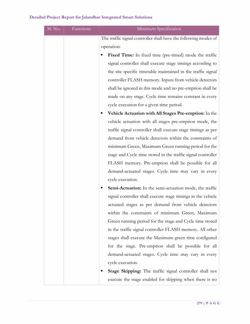
Detailed Project Report for Jalandhar Integrated Smart Solutions
279 | P A G E
Sl. No. Functions Minimum Specification
The traffic signal controller shall have the following modes of
operation:
Fixed Time: In fixed time (pre-timed) mode the traffic
signal controller shall execute stage timings according to
the site specific timetable maintained in the traffic signal
controller FLASH memory. Inputs from vehicle detectors
shall be ignored in this mode and no pre-emption shall be
made on any stage. Cycle time remains constant in every
cycle execution for a given time period.
Vehicle Actuation with All Stages Pre-emption: In the
vehicle actuation with all stages pre-emption mode, the
traffic signal controller shall execute stage timings as per
demand from vehicle detectors within the constraints of
minimum Green, Maximum Green running period for the
stage and Cycle time stored in the traffic signal controller
FLASH memory. Pre-emption shall be possible for all
demand-actuated stages. Cycle time may vary in every
cycle execution.
Semi-Actuation: In the semi-actuation mode, the traffic
signal controller shall execute stage timings in the vehicle
actuated stages as per demand from vehicle detectors
within the constraints of minimum Green, Maximum
Green running period for the stage and Cycle time stored
in the traffic signal controller FLASH memory. All other
stages shall execute the Maximum green time configured
for the stage. Pre-emption shall be possible for all
demand-actuated stages. Cycle time may vary in every
cycle execution.
Stage Skipping: The traffic signal controller shall not
execute the stage enabled for skipping when there is no

Detailed Project Report for Jalandhar Integrated Smart Solutions
280 | P A G E
Sl. No. Functions Minimum Specification
vehicle demand registered for the stage till clearance
amber time of the previous stage.
Vehicle Actuation with Fixed Cycle length: In vehicle
actuation with fixed cycle length mode, the traffic signal
controller shall execute stage timings as per demand from
vehicle detectors within the constraints of minimum
Green, Maximum Green running period for the stage and
Cycle time shall be maintained constant during a given
timeslot. Pre-emption to be carried out for all demand
actuated stages except for Priority Stage.
Full ATCS (FATCS): In FATCS mode, the traffic signal
controller shall execute stage timings as per demand
within the constraints of minimum Green, Maximum
Green running period for the stage and Cycle time
specified by the Central Computer during every cycle
switching. Pre-emption for all demand-actuated stages
except Priority Stage shall be possible in this mode. The
traffic signal controller shall identify a communication
failure with the central computer within a specified time
period. In such an event the signal plan timings shall be
executed from the local timetable stored in the traffic
signal controller FLASH memory. Fall-back mode of the
traffic signal controller shall be vehicle actuated. On
restoration of the communication with central computer,
the traffic signal controller shall automatically resort to
FATCS mode.
The traffic signal controller shall accept commands for
remote selection / de-selection of the following from the
Central Computer at JICCC.
o Hurry Call
o Flashing Amber / Flashing Red
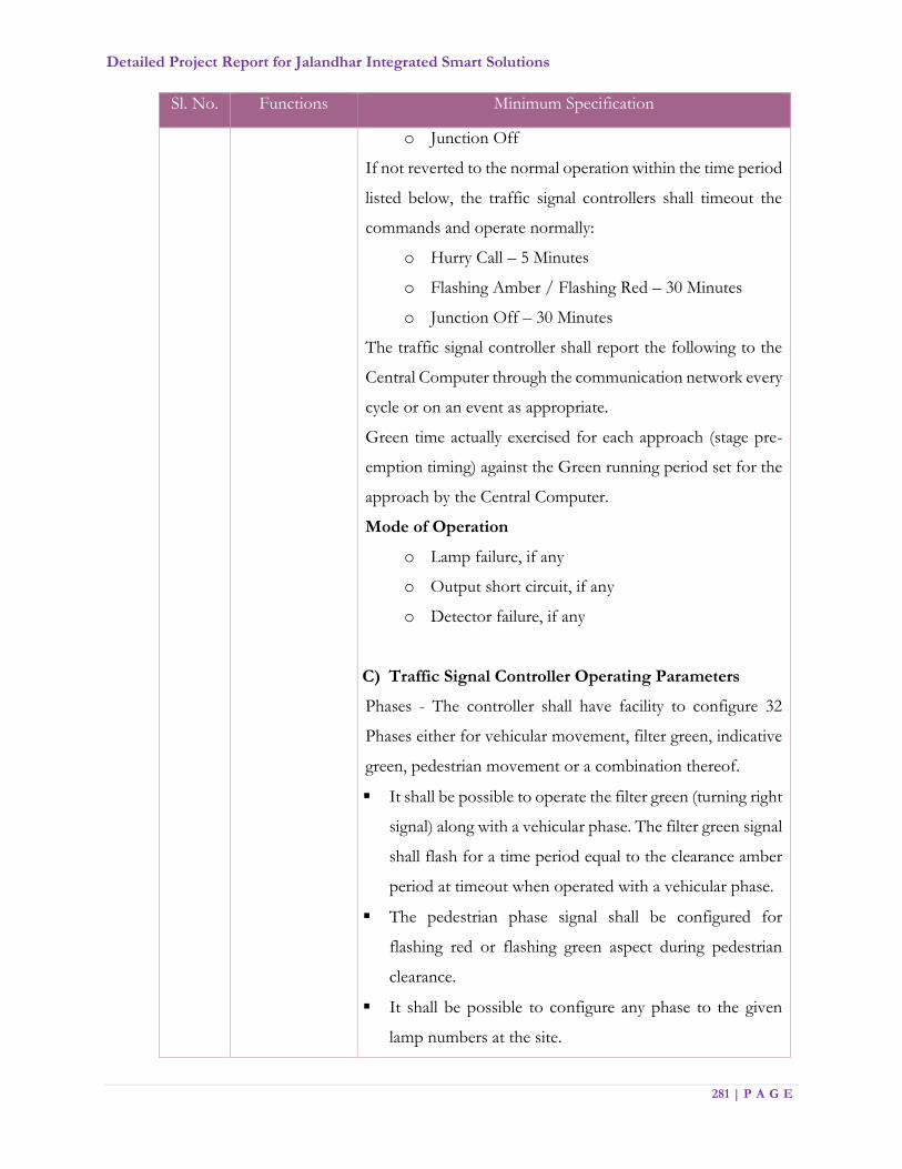
Detailed Project Report for Jalandhar Integrated Smart Solutions
281 | P A G E
Sl. No. Functions Minimum Specification
o Junction Off
If not reverted to the normal operation within the time period
listed below, the traffic signal controllers shall timeout the
commands and operate normally:
o Hurry Call – 5 Minutes
o Flashing Amber / Flashing Red – 30 Minutes
o Junction Off – 30 Minutes
The traffic signal controller shall report the following to the
Central Computer through the communication network every
cycle or on an event as appropriate.
Green time actually exercised for each approach (stage pre-
emption timing) against the Green running period set for the
approach by the Central Computer.
Mode of Operation
o Lamp failure, if any
o Output short circuit, if any
o Detector failure, if any
C) Traffic Signal Controller Operating Parameters
Phases - The controller shall have facility to configure 32
Phases either for vehicular movement, filter green, indicative
green, pedestrian movement or a combination thereof.
It shall be possible to operate the filter green (turning right
signal) along with a vehicular phase. The filter green signal
shall flash for a time period equal to the clearance amber
period at timeout when operated with a vehicular phase.
The pedestrian phase signal shall be configured for
flashing red or flashing green aspect during pedestrian
clearance.
It shall be possible to configure any phase to the given
lamp numbers at the site.
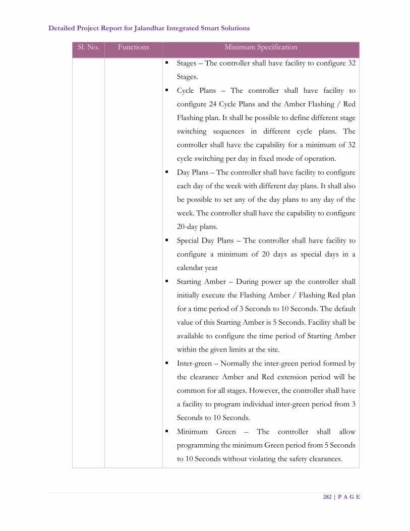
Detailed Project Report for Jalandhar Integrated Smart Solutions
282 | P A G E
Sl. No. Functions Minimum Specification
Stages – The controller shall have facility to configure 32
Stages.
Cycle Plans – The controller shall have facility to
configure 24 Cycle Plans and the Amber Flashing / Red
Flashing plan. It shall be possible to define different stage
switching sequences in different cycle plans. The
controller shall have the capability for a minimum of 32
cycle switching per day in fixed mode of operation.
Day Plans – The controller shall have facility to configure
each day of the week with different day plans. It shall also
be possible to set any of the day plans to any day of the
week. The controller shall have the capability to configure
20-day plans.
Special Day Plans – The controller shall have facility to
configure a minimum of 20 days as special days in a
calendar year
Starting Amber – During power up the controller shall
initially execute the Flashing Amber / Flashing Red plan
for a time period of 3 Seconds to 10 Seconds. The default
value of this Starting Amber is 5 Seconds. Facility shall be
available to configure the time period of Starting Amber
within the given limits at the site.
Inter-green – Normally the inter-green period formed by
the clearance Amber and Red extension period will be
common for all stages. However, the controller shall have
a facility to program individual inter-green period from 3
Seconds to 10 Seconds.
Minimum Green – The controller shall allow
programming the minimum Green period from 5 Seconds
to 10 Seconds without violating the safety clearances.

Detailed Project Report for Jalandhar Integrated Smart Solutions
283 | P A G E
Sl. No. Functions Minimum Specification
It should not be possible to pre-empt the minimum Green
once the stage start commencing execution.
All Red – Immediately after the Starting Amber all the
approaches should be given red signal for a few seconds
before allowing any right of way, as a safety measure. The
controller shall have programmability of 3 Seconds to 10
Seconds for All Red signal.
Signal lamps monitoring – The controller shall have
inbuilt circuitry to monitor the lamp status.
Green – Green Conflict Monitoring – The controller shall
have a facility to list all conflicting phases at an
intersection. The controller should not allow
programming of these conflicting phases in a Stage. A
hardware failure leading to a conflict condition (due to
faulty devices or short circuit in the output) shall force the
signal into Flashing Amber/ Flashing Red.
Cable less Synchronization – It shall be possible to
synchronize the traffic signal controllers installed in a
corridor in the following modes of operation, without
physically linking them and without communication
network. GPS enabled RTC shall be the reference for the
cable less synchronization.
Fixed Time mode with fixed offsets.
Vehicle Actuated mode with fixed offsets.
D) Input and Output facilities
Lamp Switching: The controller shall have minimum 64
individual output for signal lamp switching, configurable
from 16 to 32 lamp groups where in each group is RED,
AMBER & GREEN. The signal lamps may be operating
on appropriate DC/AC voltage of applicable rating.
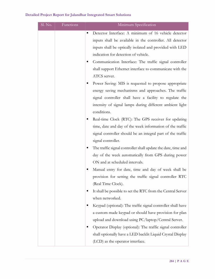
Detailed Project Report for Jalandhar Integrated Smart Solutions
284 | P A G E
Sl. No. Functions Minimum Specification
Detector Interface: A minimum of 16 vehicle detector
inputs shall be available in the controller. All detector
inputs shall be optically isolated and provided with LED
indication for detection of vehicle.
Communication Interface: The traffic signal controller
shall support Ethernet interface to communicate with the
ATCS server.
Power Saving: MIS is requested to propose appropriate
energy saving mechanisms and approaches. The traffic
signal controller shall have a facility to regulate the
intensity of signal lamps during different ambient light
conditions.
Real-time Clock (RTC): The GPS receiver for updating
time, date and day of the week information of the traffic
signal controller should be an integral part of the traffic
signal controller.
The traffic signal controller shall update the date, time and
day of the week automatically from GPS during power
ON and at scheduled intervals.
Manual entry for date, time and day of week shall be
provision for setting the traffic signal controller RTC
(Real Time Clock).
It shall be possible to set the RTC from the Central Server
when networked.
Keypad (optional): The traffic signal controller shall have
a custom made keypad or should have provision for plan
upload and download using PC/laptop/Central Server.
Operator Display (optional): The traffic signal controller
shall optionally have a LED backlit Liquid Crystal Display
(LCD) as the operator interface.

Detailed Project Report for Jalandhar Integrated Smart Solutions
285 | P A G E
Sl. No. Functions Minimum Specification
3 Vehicle
Detectors
Solution / product should be able to count vehicles at
each arm of the traffic junctions. The outputs of the
detectors shall indicate the presence of vehicles and shall
be used to influence the operation of the traffic signal
controller and shall generate counts, demands and
extensions for right-of-way. Means shall be provided so
that a detector may be connected to demand and / or
extend a phase movement as specified.
Specific placement of the detectors (upstream,
downstream, stop line, exit etc.) for independent straight
and right turn signals.
The detector shall be able to count vehicles in non-lane
based mixed traffic flow conditions and differentiate
between different vehicle types (two-wheeler, three-
wheeler, car, HGV, etc.). The accuracy of counts shall be
bigger than 90% over all light and weather conditions.
A detector that does not change its status at least once
during a stage execution shall be notified to the Central
Computer (in ATCS mode) at the termination of the
associated stage.
4 Communication
Network
Function of the Communication network is for remote
monitoring of the intersection and its management. Real
time data (like RTC time, stage timing, mode, events, etc.)
from the traffic signal controller is required to be sent to
the Central Computer in Traffic Management Centre.
Central Computer running the ATCS application shall
calculate and send optimum signal timings to all
intersections in the corridor.
5 ATCS
Application
software
Objective of the ATCS is to minimize the stops and delays in
a road network to decrease the travel time with the help of
state-of-the-art technology. The adaptive traffic control
Detailed Project Report for Jalandhar Integrated Smart Solutions
286 | P A G E
Sl. No. Functions Minimum Specification
system will provide simulation based real time traffic flow
modelling capability with the capacity to calculate traffic
flows, OD movements, and queues and turning movement
along entire primary road transport network in the defined
study area covering the ATCS junctions and beyond. The
Application software or platform will be able to predict traffic
flow in the network for the near term over various interval
horizons (e.g. T+5, T+10 … T+30 mins). The ATCS
application will provide estimated traffic flow for each of the
junction to calculate optimal cycle times, effective green time
ratios, and change intervals for all system traffic signal
controllers connected to it either as individual junctions or
groups of junctions. These calculations will be based up on
assessments carried out by the ATCS application software
running on a Central Computer based on the data and
information gathered by vehicle detectors at strategic
locations at the intersections controlled by the system. The
ATCS application software shall be divided into two modules
with the following as the expected capabilities of the
individual modules
Module 1: Real Time Traffic Prediction Capability
Shall provide a decision support tool for assessing
strategies to minimize congestion, delays and emergency
response time to events via simulation and planning tools
liked with real time traffic data fusion and control of traffic
Signalling infrastructure on ground.
Shall collect continuously information about current
observed traffic conditions from a variety of data sources
(like Bus GPS data, parking data, mobile phone data etc.
MSI can propose alternate data sources that could be
Detailed Project Report for Jalandhar Integrated Smart Solutions
287 | P A G E
Sl. No. Functions Minimum Specification
integrated) and of different kind (traffic states, signal
states, vehicle trajectories, incidents, road works etc.)
Shall infer a coherent and comprehensive observed traffic
state (speeds, vehicular densities, and presence of queues)
on all network elements, from above mentioned
observations, including vehicle trajectories, through a
number of map matching, data validation, harmonization
and fusion processes.
Shall have a Graphical User Interface (GUI) to be able to
display traffic state along the observed and unobserved
parts of the network through GIS maps The MSI is
expected to create a layer of edge equipment within that
GIS platform and integrate with ATMS modules of the
transport network and must be able to display traffic flow,
building of queues, delays, location of traffic signals and
junctions, key Points of Interests (POI), Variable Message
signs etc. In addition, the GUI must be:
Flexible for the operators to zoom and navigate with
ability to interact with objects on the map.
Should be interoperable across multiple platforms
and key graphical results and MIS must be made
available across the Web
Graphically present time-space diagram for selected
corridors on desktop
Graphically present signal plan execution and traffic
flow at the intersection on desktop
Shall have the ability to predict, forecast and estimate the
traffic pattern across the signals over the near term future
(e.g. T+5, T+10, T+15, T+30 mins … T + 1 hour)
Shall extrapolate the measurements made on a limited
number of junctions and arms along the rest of the

Detailed Project Report for Jalandhar Integrated Smart Solutions
288 | P A G E
Sl. No. Functions Minimum Specification
unmonitored network, and obtain an estimation of the
traffic state of the complete network and the evolution of
this traffic state over the near term future (e.g. T+5, T+10,
T+15, T+30 mins … T + 1 hour)
Shall be able to forecast the traffic state with respect to
current incidents and traffic management strategies (e.g.
traffic signal control or variable message signs), improving
the decision making capabilities of the operators even
before problems occur
Shall provide customizable estimates of Key Performance
Indicators (KPI) for alternate traffic management
strategies to quickly assess the results
Shall provide calculated traffic flows estimation and
forecast, queues and delays to Urban Control and
Adaptive Traffic Control Systems, allowing for proactive
Traffic Management and Control.
To raise alerts to the operator that trigger on customizable
conditions in the network (starting with simple drops in
flow, up to total queue lengths along emission sensitive
roads surpassing a definable threshold); To distribute both
collected and calculated traffic information via a variety of
communication protocols and channels, ensuring high
interoperability degree and thus acting as a “traffic data
and information hub.
Shall include a traffic data warehouse (for minimum 4
years) for all historic traffic information gathered from the
hardware installed on the road network. MSI to propose
how data storage requirements could be minimized using
consolidation techniques.

Detailed Project Report for Jalandhar Integrated Smart Solutions
289 | P A G E
Sl. No. Functions Minimum Specification
Shall operate in real time that is continuously updating the
estimates on the state of the network and the travel times
on the basis of data collected continuously over time.
Shall operate the traffic lights with the adaptive traffic
controls, based on the current and
Forecasted traffic demand and the current incidents, thus
optimizing the green waves continuously throughout the
network
Shall be possible to interface the ATCS with a popular
microscopic traffic flow simulation software for pre and
post implementation analysis and study of the proposed
ATCS control strategy.
Module 2: Adaptive Traffic Control System
To operate the traffic lights with the adaptive traffic
controls based on the current and forecasted traffic
demand from the above Real Time Traffic Prediction
Tool including the current incidents, thus optimizing the
green waves continuously throughout the network.
Enable a smart public transport priority respecting the
delays for all road users at once with the adaptive signal
controller. To have the capability to integrate with Bus
GPS data to identify oncoming buses at the junction and
be able to provide priority clearance of buses.
Identify the critical junction (Master Junction) for each of
the defined corridor or a region based on maximum traffic
demand and saturation.
The critical junction cycle time estimated shall be used as
the group cycle time i.e. cycle time common to all
intersection in that corridor or region.

Detailed Project Report for Jalandhar Integrated Smart Solutions
290 | P A G E
Sl. No. Functions Minimum Specification
Stage optimization to the best level of service shall be
carried out based on the traffic demand.
Cycle optimization shall be carried out by increasing or
decreasing the common corridor cycle time based on the
traffic demand within the constraints of minimum and
Maximum designed value of cycle time.
Offset correction shall be carried out to minimize number
of stops and delays along the corridor for the priority
route and for the adjoining road network at once. Offset
deviation shall be calculated with a traffic flow model
based on the distance, traffic demand and speed between
successive intersections and be corrected within 5 Minutes
maximum.
The system shall have provision to configure priority for
upstream signals as default. The ATCS software shall
continuously check the traffic demand for upstream and
downstream traffic and automatically assign the priority
route to the higher demand direction.
The system shall use optimization algorithms that
minimize a function based on the delays, number of stops
and queue lengths simultaneously, using a traffic flow
model, thus providing a true optimum for all road users.
Develop appropriate stage timing plans for each approach
of every intersection under the ATCS, based on real time
demand and the predicted traffic flow values from the
traffic flow model.
Propose timing plans to every intersection under the
ATCS at least every five minutes.
Calculate the current queue lengths for each approach that
has detection cycle-by-cycle based on the succession of
time gaps between cars.

Detailed Project Report for Jalandhar Integrated Smart Solutions
291 | P A G E
Sl. No. Functions Minimum Specification
Adjust the proposed timing plans second-by-second
according to the current and past detector states and the
current queue lengths for every intersection under
detection.
Enable transit signal priority with minimize disruption of
car traffic, dependent on predefined weights for public
transport vehicles in comparison to individual traffic. In
order to decrease the workload for operation and
maintenance, each supply item (road network, lanes,
signals and detectors) shall be supplied just once, so that
the all macro and microscopic traffic models and the
microscopic traffic flow software used for calibration and
verification of the ATCS share the same supply.
Shall provide calculated traffic flows estimation and
forecast, queues and delays to Urban Control and
Adaptive Signal Control Systems, allowing for proactive
Traffic Management and Control. Such estimation will be
updated at least every 5 minutes or less, and will not be
based on a machine learning approach that would not
provide enough flexibility in case of unexpected events.
Should be able to route emergency vehicles to minimize
the impact of events on the travel time of emergency
vehicles.
Shall be able to export the calculated traffic flow data
continually to a multi-modal journey-planner that allows
all internet users in the city to find the best route with each
traffic mode based on the current travel times in the
network.
Identify Priority routes and synchronize traffic in the
Priority routes.
Detailed Project Report for Jalandhar Integrated Smart Solutions
292 | P A G E
Sl. No. Functions Minimum Specification
Manage and maintain communication with traffic signal
controllers under ATCS.
Maintain database for time plan execution and system
performance.
Maintain error logs and system logs.
Generate Reports on request: - The ATCS shall generate
standard and custom reports for planning and analysis.
Reports
System shall generate Corridor based and Intersection based
reports. The application software shall generate the following
reports, but not limited to the below. All the reports shall be
possible for selected dates.
Intersection based reports
Stage Timing report – The report shall give details of time
at which every stage change has taken place. The report
shall show the stage sequence, stage timings and stage
saturation of all stages of all cycles for a day. The
saturation is defined as the ratio between the available
stage timings to the actual stage timing executed by the
traffic signal controller for the stage (stage pre-emption
time).
Cycle Timing report – The report shall give details of time
at which every cycle has taken place. The report shall show
the cycle sequence and cycle timings for all the cycles in a
day.
Stage switching report – The report shall give details of
time at which a stage switching has taken place. The report
shall show the stage sequence, stage timings and stage
saturation for a day.
Detailed Project Report for Jalandhar Integrated Smart Solutions
293 | P A G E
Sl. No. Functions Minimum Specification
Cycle Time switching report – The report shall give details
of time at which a cycle switching has taken place. The
report shall show the cycle sequence and cycle timings for
the cycle in a day.
Mode switching report – The report shall give details of
the mode switching taken place on a day.
Event Report - The report shall show events generated by
the controller with date and time of event.
Power on & down: The report shall show time when the
master is switched on, and last working time of the master
controller.
Intensity Change – The report shall show the brightness
of the signal lamp is changed according to the light
intensity either manually through keypad or automatically
by LDR with time stamp.
Plan Change – The report shall show the time of change
of plan either through keypad or remotely through a PC
or Server.
RTC Failure – The report shall show the time when RTC
battery level goes below the threshold value.
Time Update – The report shall show the time when the
Master controller updated its time either manually through
keypad, automatically by GPS or through remote server.
Mode Change – The report shall show the time when
Master controller’s operating mode is changed either
manually through keypad or a remote server. The typical
modes are FIXED, FULL VA SPLIT, FULL VA CYCLE,
FLASH, LAMP OFF and HURRY CALL.
Lamp Status Report – The report shall show lamp failure
report with date and time of failure, color of the lamp and
associated phase.
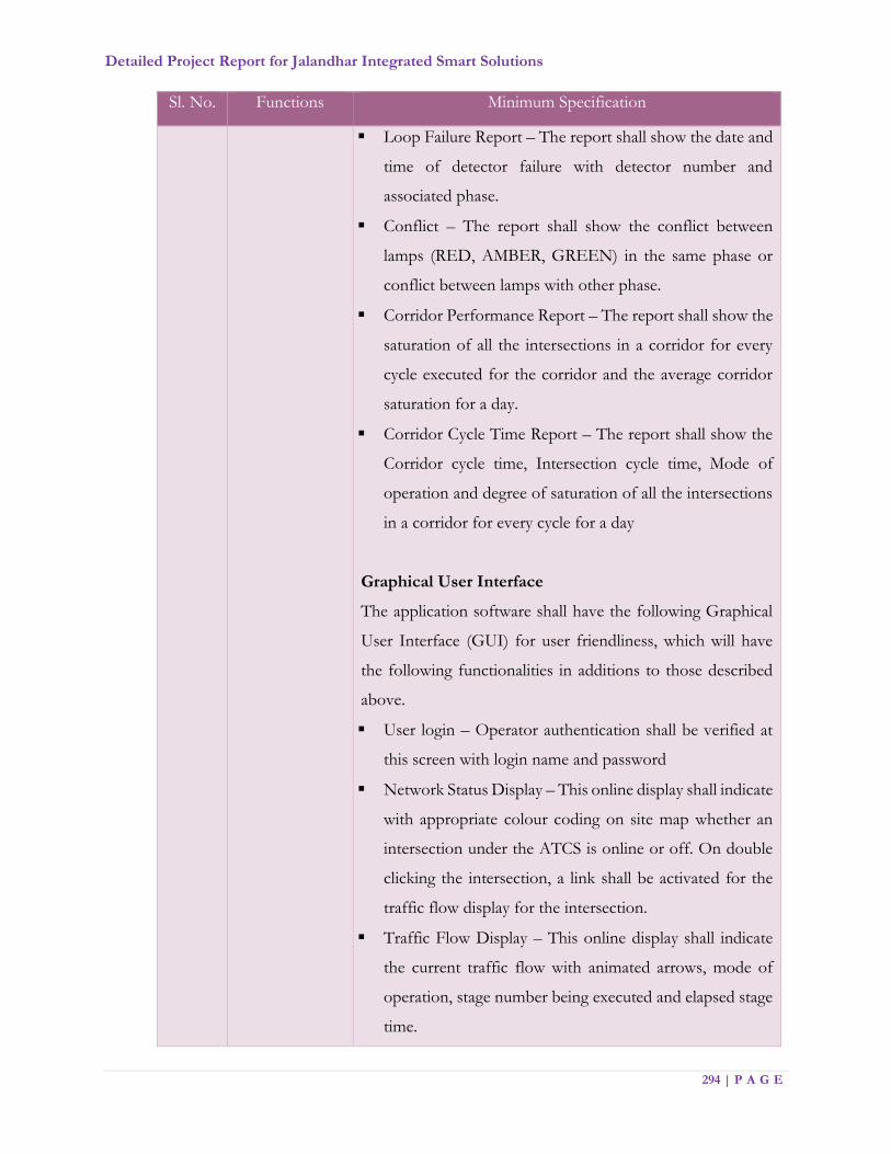
Detailed Project Report for Jalandhar Integrated Smart Solutions
294 | P A G E
Sl. No. Functions Minimum Specification
Loop Failure Report – The report shall show the date and
time of detector failure with detector number and
associated phase.
Conflict – The report shall show the conflict between
lamps (RED, AMBER, GREEN) in the same phase or
conflict between lamps with other phase.
Corridor Performance Report – The report shall show the
saturation of all the intersections in a corridor for every
cycle executed for the corridor and the average corridor
saturation for a day.
Corridor Cycle Time Report – The report shall show the
Corridor cycle time, Intersection cycle time, Mode of
operation and degree of saturation of all the intersections
in a corridor for every cycle for a day
Graphical User Interface
The application software shall have the following Graphical
User Interface (GUI) for user friendliness, which will have
the following functionalities in additions to those described
above.
User login – Operator authentication shall be verified at
this screen with login name and password
Network Status Display – This online display shall indicate
with appropriate colour coding on site map whether an
intersection under the ATCS is online or off. On double
clicking the intersection, a link shall be activated for the
traffic flow display for the intersection.
Traffic Flow Display – This online display shall indicate
the current traffic flow with animated arrows, mode of
operation, stage number being executed and elapsed stage
time.
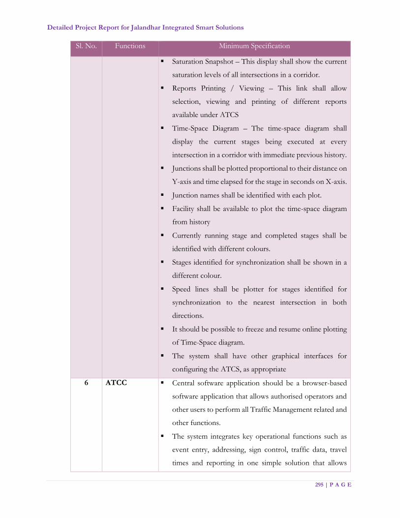
Detailed Project Report for Jalandhar Integrated Smart Solutions
295 | P A G E
Sl. No. Functions Minimum Specification
Saturation Snapshot – This display shall show the current
saturation levels of all intersections in a corridor.
Reports Printing / Viewing – This link shall allow
selection, viewing and printing of different reports
available under ATCS
Time-Space Diagram – The time-space diagram shall
display the current stages being executed at every
intersection in a corridor with immediate previous history.
Junctions shall be plotted proportional to their distance on
Y-axis and time elapsed for the stage in seconds on X-axis.
Junction names shall be identified with each plot.
Facility shall be available to plot the time-space diagram
from history
Currently running stage and completed stages shall be
identified with different colours.
Stages identified for synchronization shall be shown in a
different colour.
Speed lines shall be plotter for stages identified for
synchronization to the nearest intersection in both
directions.
It should be possible to freeze and resume online plotting
of Time-Space diagram.
The system shall have other graphical interfaces for
configuring the ATCS, as appropriate
6 ATCC Central software application should be a browser-based
software application that allows authorised operators and
other users to perform all Traffic Management related and
other functions.
The system integrates key operational functions such as
event entry, addressing, sign control, traffic data, travel
times and reporting in one simple solution that allows
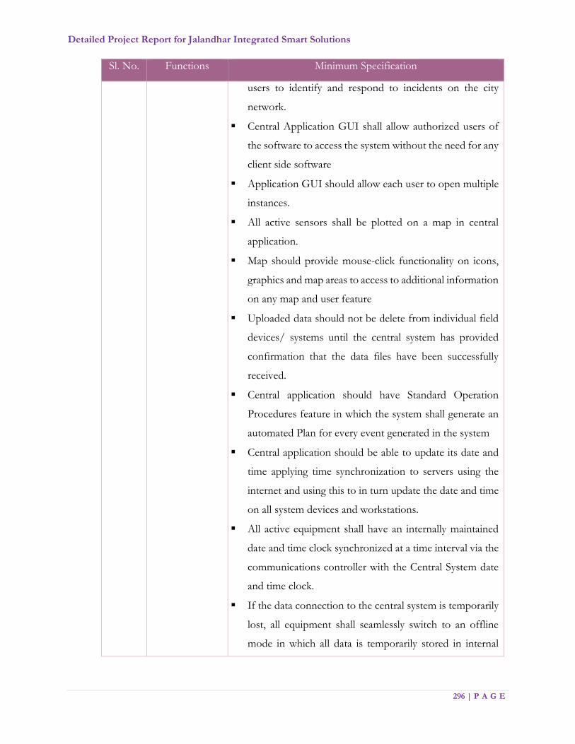
Detailed Project Report for Jalandhar Integrated Smart Solutions
296 | P A G E
Sl. No. Functions Minimum Specification
users to identify and respond to incidents on the city
network.
Central Application GUI shall allow authorized users of
the software to access the system without the need for any
client side software
Application GUI should allow each user to open multiple
instances.
All active sensors shall be plotted on a map in central
application.
Map should provide mouse-click functionality on icons,
graphics and map areas to access to additional information
on any map and user feature
Uploaded data should not be delete from individual field
devices/ systems until the central system has provided
confirmation that the data files have been successfully
received.
Central application should have Standard Operation
Procedures feature in which the system shall generate an
automated Plan for every event generated in the system
Central application should be able to update its date and
time applying time synchronization to servers using the
internet and using this to in turn update the date and time
on all system devices and workstations.
All active equipment shall have an internally maintained
date and time clock synchronized at a time interval via the
communications controller with the Central System date
and time clock.
If the data connection to the central system is temporarily
lost, all equipment shall seamlessly switch to an offline
mode in which all data is temporarily stored in internal
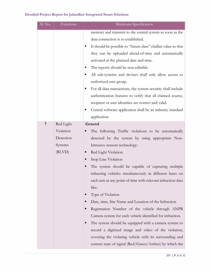
Detailed Project Report for Jalandhar Integrated Smart Solutions
297 | P A G E
Sl. No. Functions Minimum Specification
memory and transmit to the central system as soon as the
data connection is re-established.
It should be possible to “future-date” challan value so that
they can be uploaded ahead-of-time and automatically
activated at the planned date and time.
The reports should be non-editable.
All sub-systems and devices shall only allow access to
authorized user group.
For all data transactions, the system security shall include
authentication features to verify that all claimed source,
recipient or user identities are correct and valid.
Central software application shall be an industry standard
application
7 Red Light
Violation
Detection
Systems
(RLVD)
General
The following Traffic violations to be automatically
detected by the system by using appropriate Non-
Intrusive sensors technology:
Red Light Violation
Stop Line Violation
The system should be capable of capturing multiple
infracting vehicles simultaneously in different lanes on
each arm at any point of time with relevant infraction data
like:
Type of Violation
Date, time, Site Name and Location of the Infraction
Registration Number of the vehicle through ANPR
Camera system for each vehicle identified for infraction.
The system should be equipped with a camera system to
record a digitized image and video of the violation,
covering the violating vehicle with its surrounding and
current state of signal (Red/Green/Amber) by which the

Detailed Project Report for Jalandhar Integrated Smart Solutions
298 | P A G E
Sl. No. Functions Minimum Specification
system should clearly show nature of violation and proof
thereof:
When it violates the stop line.
When it violates the red signal.
Besides, a closer view indicating readable registration
number plate patch of the violating vehicle for court
evidence for each violation
The system shall be able to detect all vehicles infracting
simultaneously in each lane/ arm at the junction as per
locations provided. It should also be able to detect the
vehicles infracting serially one after another in the same
lane. The vehicles should be clearly identifiable and
demarcated in the image produced by the camera system.
The Evidence image produced by the system should be
wide enough to give the exact position of the infracting
vehicles with respect to the stop line and clearly indicate
colour of the Traffic light at the instant of Infraction even
if any other means is being used to report the colour of
the light.
The system should interface with the traffic controller to
validate the colour of the traffic signal reported at the time
of Infraction so as to give correct inputs of the signal
cycle.
The Evidence and ANPR camera should continuously
record all footage in its field of view to be stored at the
local base station. This should be extractable onto a
portable device as and when required. The option of live
viewing of evidence cameras from the locations shall be
available at the JICCC. The network should have the
capability to provide the real time feed of the evidence

Detailed Project Report for Jalandhar Integrated Smart Solutions
299 | P A G E
Sl. No. Functions Minimum Specification
camera to the JICCC at the best resolution possible on the
available network
The system shall be equipped with IR Illuminator to
ensure clear images including illumination of the Number
Plate and capture the violation image under low light
conditions and night time.
In case of violation, lights should flash immediately
Recording & display information archive medium
The recording and display of information should be
detailed on the snapshot of the infracting vehicle as
follows:
o Computer generated unique ID of each violation
o Date (DD/MM/YYYY)
o Time (HH:MM: SS)
o Equipment ID
o Location ID
o Carriageway or direction of violating vehicle
o Type of Violation (Signal/Stop Line)
o Lane Number of violating vehicle
o Time into Red/Green/Amber
o Registration Number of violating vehicle
The size of file chunks that a camera should send to CC
should be configurable
On site-out station processing unit communication &
Electrical Interface
The system should automatically reset in the event of a
program hang up and restart on a button press. However,
the system should start automatically after power failure.

Detailed Project Report for Jalandhar Integrated Smart Solutions
300 | P A G E
Sl. No. Functions Minimum Specification
The system should have secure access mechanism for
validation of authorized personnel.
Deletion or addition and transfer of data should only be
permit to authorized users.
A log of all user activities should be maintain in the
system.
Roles and Rights of users should be defined in the system
as per the requirements of the JSCL
All formats of the stored data with respect to the
infractions should be Non Proprietary
The communication between the on-site outstation-
processing unit housed in the junction box and the
detection systems mounted on the cantilever shall be
through appropriate secured technology.
The system should have the capability to transfer the data
to SP’s Office through proper encryption in real time and
batch mode for verification of the infraction and
processing of challan. Call forwarding architecture shall be
followed to avoid any data loss during transfer
In the event that the connectivity to the SP’s Office is not
establish due to network/connectivity failures, then all
data pertaining to the infraction shall be stored on site and
will be transferred once the connectivity is re-established
automatically. There shall also be a facility of physical
transfer of data on portable device whenever required.
There should be a provision to store minimum one week
of data at each site on a 24x7 basis.
Mounting Structure
Should be cantilever mounted and shall have minimum 6
Metres. height with appropriate vertical clearance under
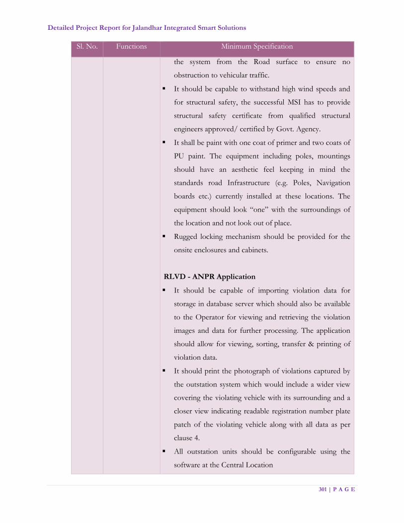
Detailed Project Report for Jalandhar Integrated Smart Solutions
301 | P A G E
Sl. No. Functions Minimum Specification
the system from the Road surface to ensure no
obstruction to vehicular traffic.
It should be capable to withstand high wind speeds and
for structural safety, the successful MSI has to provide
structural safety certificate from qualified structural
engineers approved/ certified by Govt. Agency.
It shall be paint with one coat of primer and two coats of
PU paint. The equipment including poles, mountings
should have an aesthetic feel keeping in mind the
standards road Infrastructure (e.g. Poles, Navigation
boards etc.) currently installed at these locations. The
equipment should look “one” with the surroundings of
the location and not look out of place.
Rugged locking mechanism should be provided for the
onsite enclosures and cabinets.
RLVD - ANPR Application
It should be capable of importing violation data for
storage in database server which should also be available
to the Operator for viewing and retrieving the violation
images and data for further processing. The application
should allow for viewing, sorting, transfer & printing of
violation data.
It should print the photograph of violations captured by
the outstation system which would include a wider view
covering the violating vehicle with its surrounding and a
closer view indicating readable registration number plate
patch of the violating vehicle along with all data as per
clause 4.
All outstation units should be configurable using the
software at the Central Location
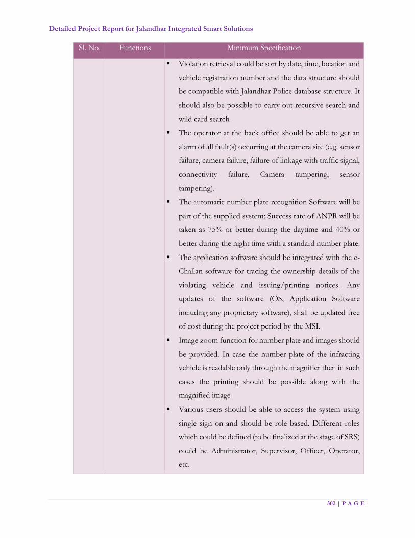
Detailed Project Report for Jalandhar Integrated Smart Solutions
302 | P A G E
Sl. No. Functions Minimum Specification
Violation retrieval could be sort by date, time, location and
vehicle registration number and the data structure should
be compatible with Jalandhar Police database structure. It
should also be possible to carry out recursive search and
wild card search
The operator at the back office should be able to get an
alarm of all fault(s) occurring at the camera site (e.g. sensor
failure, camera failure, failure of linkage with traffic signal,
connectivity failure, Camera tampering, sensor
tampering).
The automatic number plate recognition Software will be
part of the supplied system; Success rate of ANPR will be
taken as 75% or better during the daytime and 40% or
better during the night time with a standard number plate.
The application software should be integrated with the e-
Challan software for tracing the ownership details of the
violating vehicle and issuing/printing notices. Any
updates of the software (OS, Application Software
including any proprietary software), shall be updated free
of cost during the project period by the MSI.
Image zoom function for number plate and images should
be provided. In case the number plate of the infracting
vehicle is readable only through the magnifier then in such
cases the printing should be possible along with the
magnified image
Various users should be able to access the system using
single sign on and should be role based. Different roles
which could be defined (to be finalized at the stage of SRS)
could be Administrator, Supervisor, Officer, Operator,
etc.
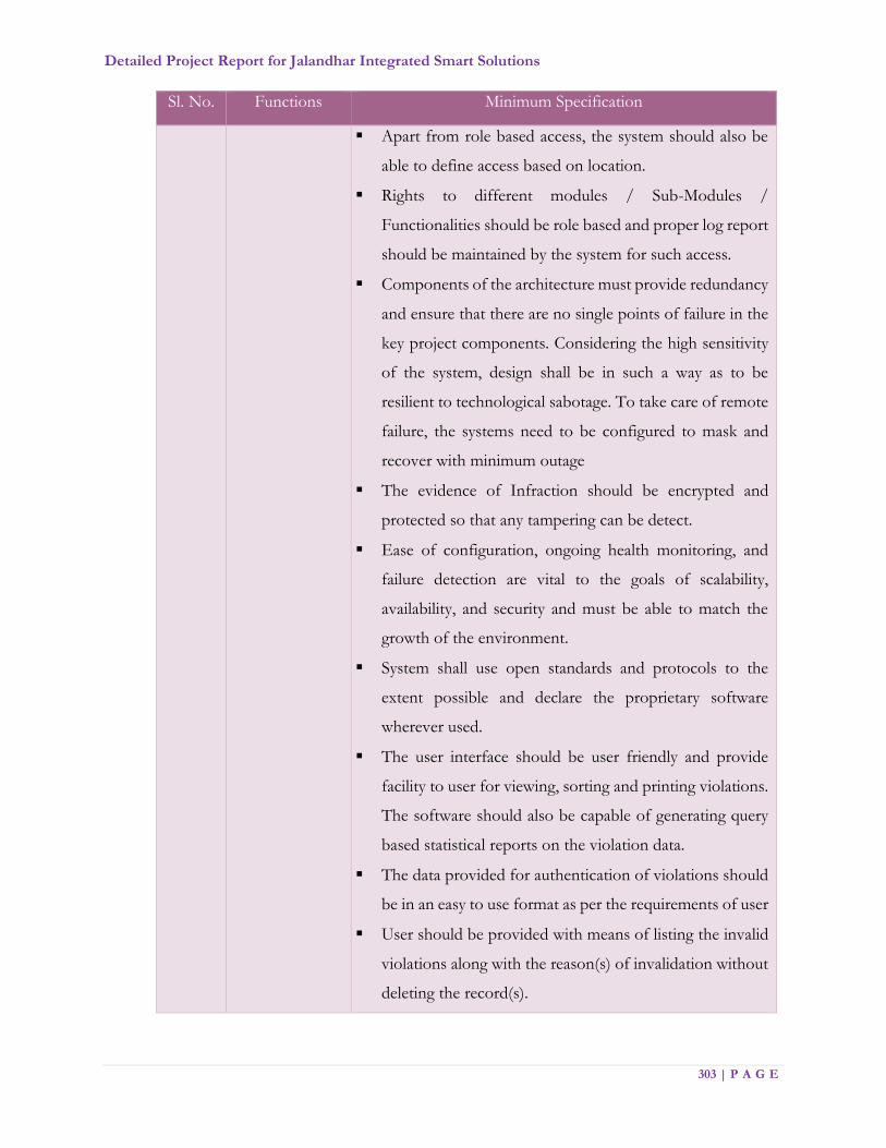
Detailed Project Report for Jalandhar Integrated Smart Solutions
303 | P A G E
Sl. No. Functions Minimum Specification
Apart from role based access, the system should also be
able to define access based on location.
Rights to different modules / Sub-Modules /
Functionalities should be role based and proper log report
should be maintained by the system for such access.
Components of the architecture must provide redundancy
and ensure that there are no single points of failure in the
key project components. Considering the high sensitivity
of the system, design shall be in such a way as to be
resilient to technological sabotage. To take care of remote
failure, the systems need to be configured to mask and
recover with minimum outage
The evidence of Infraction should be encrypted and
protected so that any tampering can be detect.
Ease of configuration, ongoing health monitoring, and
failure detection are vital to the goals of scalability,
availability, and security and must be able to match the
growth of the environment.
System shall use open standards and protocols to the
extent possible and declare the proprietary software
wherever used.
The user interface should be user friendly and provide
facility to user for viewing, sorting and printing violations.
The software should also be capable of generating query
based statistical reports on the violation data.
The data provided for authentication of violations should
be in an easy to use format as per the requirements of user
User should be provided with means of listing the invalid
violations along with the reason(s) of invalidation without
deleting the record(s).

Detailed Project Report for Jalandhar Integrated Smart Solutions
304 | P A G E
Sl. No. Functions Minimum Specification
Basic image manipulation tools (zoom etc.) should be
provide for the displayed image but the actual recorded
image should never change.
Log of user actions be maintained in read only mode. User
should be provided with the password and ID to access
the system along with user type (admin, user).
Image should have a header/footer depicting the
information about the site IP and violation details like
date, time, equipment ID, location ID, Unique ID of each
violation, lane number, Regn. Number of violating vehicle
and actual violation of violating vehicle etc. so that the
complete lane wise junction behaviour is recorded
including (Speed of violating vehicle, notified speed limit,
Signal Jumping, Stop Line Violation, Speed Violation with
Registration Number Plate Recognition facility.
Number plate should be readable automatically by the
software/interface. There should be user interface for
simultaneous manual authentication / correction and
saving as well. Number plate should be readable
automatically by the software/interface. There should be
user interface for simultaneous manual authentication /
correction and saving as well
Interface for taking prints of the violations (including
image and above details).
8 e-Challan
Application
The objective of the e-Challan application is as follows:
Issuing challan for traffic violations on a 24x7 basis.
Maintaining the details pertaining to all the activities of the
Traffic circles/violations/violators.
Providing requisite structured/unstructured information
to the traffic management officials as and when required.

Detailed Project Report for Jalandhar Integrated Smart Solutions
305 | P A G E
Sl. No. Functions Minimum Specification
Generating various statutory reports for the
administrative use and functioning of the Traffic unit in
matters of prosecution of violators and monitoring the
functioning of field officers.
Integrating and networking the system with state-of-the-
art hardware and application software for the Traffic
Police to access and using the information in their day-to-
day work.
The following are the key functional requirements of the e-
Challan System:
E-challan system shall be able to retrieve vehicle owners
details and vehicle data from RTO data base to minimize
data entry
E-challan system shall be able to retrieve vehicle
registration details and driving license details by reading
appropriate smart card to minimize data entry
Server should maintain log of all current devices. Any
access to the system must be recorded along with date,
time, user id and IP address
Traffic officer should log in to the hand held device
through the unique user id and pass word or smart card
issued for the purpose
A unique Challan number should be generated through
software for each challan
As soon as a vehicle registration number is entered, the
handheld device should automatically check from the
server if the vehicle is stolen, wanted in any criminal case
or is in the list of suspicious vehicle
The most frequent traffic offences should be kept at the
top in the drop down menu and offence details should be
available if required by officer

Detailed Project Report for Jalandhar Integrated Smart Solutions
306 | P A G E
Sl. No. Functions Minimum Specification
Date, time and GPS coordinates of place of challan should
be automatically populated in the relevant fields of
software
Compounding amount must populate in the field
automatically from master table
The successful MSI should develop the GUI and
functionality as per requirements of the Jalandhar Traffic
Police
The GUI should be Multi lingual i.e., English, Hindi and
Punjabi
It should be possible to integrate payment gate way
operator interface with the system for facilitation of
payment
The Application Software should work in a web-based
environment.
The application software should be user friendly, easy to
operate
The software must provide comprehensive data back-up
and restoration capability.
The system will function in web-based system where the
hand-held device shall work as a node.
The application software should maintain the logs of user
activities to facilitate the audit trail.
The system should have sufficient security features such
as firewall, access control system, biometrics, password
protection, audit trail, anti-virus etc.
Database server should be able to handle the activities of
all the handheld devices at one time simultaneously with
huge database size of prosecution, ownerships, driving
license etc., without affecting the performance.
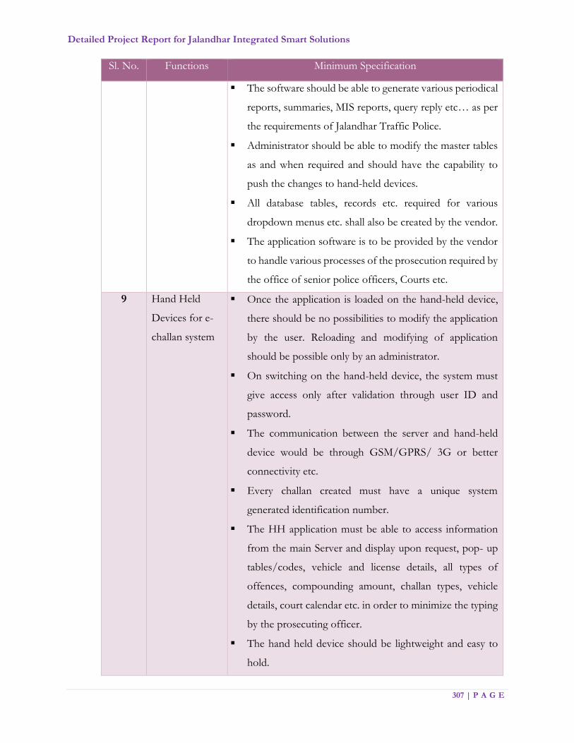
Detailed Project Report for Jalandhar Integrated Smart Solutions
307 | P A G E
Sl. No. Functions Minimum Specification
The software should be able to generate various periodical
reports, summaries, MIS reports, query reply etc… as per
the requirements of Jalandhar Traffic Police.
Administrator should be able to modify the master tables
as and when required and should have the capability to
push the changes to hand-held devices.
All database tables, records etc. required for various
dropdown menus etc. shall also be created by the vendor.
The application software is to be provided by the vendor
to handle various processes of the prosecution required by
the office of senior police officers, Courts etc.
9 Hand Held
Devices for e-
challan system
Once the application is loaded on the hand-held device,
there should be no possibilities to modify the application
by the user. Reloading and modifying of application
should be possible only by an administrator.
On switching on the hand-held device, the system must
give access only after validation through user ID and
password.
The communication between the server and hand-held
device would be through GSM/GPRS/ 3G or better
connectivity etc.
Every challan created must have a unique system
generated identification number.
The HH application must be able to access information
from the main Server and display upon request, pop- up
tables/codes, vehicle and license details, all types of
offences, compounding amount, challan types, vehicle
details, court calendar etc. in order to minimize the typing
by the prosecuting officer.
The hand held device should be lightweight and easy to
hold.
Detailed Project Report for Jalandhar Integrated Smart Solutions
308 | P A G E
Sl. No. Functions Minimum Specification
The HH device should be able to access data/ information
on the basis of driving license number, vehicle registration
number etc. from the main server data relating to previous
offences.
The hand-held application software should also suggest
date of challan, place of challan, name of the Court and
court date etc. to further reduce typing by the officer.
These fields should be design in consultation with
Jalandhar Traffic Police.
When a challan is issue, the name and ID of the officer
should be print on the Challan.
The HH device must be able to input and print multiple
offences on the same Challan
The HHD software must validate Challan fields
automatically before the Challan is printed. The system
must ensure that certain fields are properly complete
before allowing the Challan to be printed.
When downloading application software or pop-up tables
or lists to the HH, or uploading challan records to the
Server, synchronization of HH system must be automatic,
in order to minimize human intervention
Uploading data to the Database Server should be
automatic in consistent manner.
The application should provide features wherein when a
driving license/ vehicle registration number is entered; it
should be able to pull from the server all the details
relating to the driving license holder/ vehicle owner
including history of previous offences.
Software should capture the list of documents seized
during prosecution and such list must be reflected on the
printed court challan.
Detailed Project Report for Jalandhar Integrated Smart Solutions
309 | P A G E
Sl. No. Functions Minimum Specification
The handheld application software shall allow the user to
generate a summary report to facilitate evaluation of his
daily work. The entire day report of the official be auto
submitted to the administrator at the end of the day or
closing hours of the official duty when HH is submitted
at Office
Once the Challan is complete and saved, any further
editing should not be possible unless so authorized by
administrator.
Each hand-held device should be provided with original
printed user manual and appropriate carry case for HH
device with charger.
The application software should allow online payment
though payment gateway
There should be automatic rejection of payment for the
settlement of expired notices or challans. Partial payment
of an offence must not be accepted by the system
including previous violations fees.
The software should update DL/RC smart card with the
booked offence.
10 Public Address
System
The Public Address System (PAS) should be capable of
addressing citizens at specific locations from the JICCC.
The proposed system shall contain an IP-based
announcing control connected to the JICCC.
Public Address System shall be used at intersections,
public places, market places or those critical locations as
identified by JSCL to make important announcements for
the public. It shall be able to broadcast messages across all
PAS or specific announcement could be made to a
particular location supporting single zone / multi zone
operations. The system shall also deliver pre-recorded
Detailed Project Report for Jalandhar Integrated Smart Solutions
310 | P A G E
Sl. No. Functions Minimum Specification
messages to the loud speakers attached to them from
CD/DVD Players & Pen drives for public
announcements.
The system shall contain an IP-based amplifier and uses
PoE / PoE+ power that could drive the speakers. The
system shall also contain the control software that could
be used to control/monitor all the components of the
system that includes Controller, Calling Station & keypad,
Amplifier (Mixing & Booster).
The SI shall describe in detail the design, operational and
physical requirements of the proposed public
announcement system to demonstrate compliance with all
the specified requirements that will be mentioned in BID
DOCUMENT.
PAS master controller should have function keys for
selecting the single location, group of locations or all
locations, simple operation on broadcasting to any
terminal or separated zones.
PAS master controller should facilitate multiple MIC
inputs and audio inputs.
IP and PC based solution – easy to use and maintain
Remote configuration and administration
PoE/PoE+ or 12V power
10/100Base-TX Ethernet
The system should not be an end of life / end of service
product.
11 Emergency call
Box
The emergency box (or panic button) will enable citizens
to establish a two-way audio (microphone and speaker) –
video (video camera and a video screen) communication
link with operation staff at JICCC (or other locations

Detailed Project Report for Jalandhar Integrated Smart Solutions
311 | P A G E
Sl. No. Functions Minimum Specification
where control solutions is deployed) through a press of a
button.
Emergency Call box to be strategically located, suitably
sized and identified/clearly labelled for “Emergency”.
Emergency button once pressed will send a call to the
nearest police station.
The emergency feature must also be available within the
mobile app which will enable the user to initiate a
bidirectional audio – video call with operation staff at
JICCC. In absence of connectivity, the application should
send the current location and contact number of the
citizen using emergency feature through text message to
JICCC.
7.5.7. Technical Specifications
ANPR LIU
Sl. No Minimum Specification
1. Shall have minimum Quad Core CPU (4 physical CPU cores)
2. Shall have minimum 64-bit architecture
3. Shall have minimum 8 GB RAM (DDR3-1600 or above)
4. Shall have minimum 500 GB Hard Disk
5. Shall have Dedicated Gigabit network port per camera (MTU 9000 / jumbo frames), +1 LAN port
6. Shall have capability to connect 4 cameras per LPU
Detailed Project Report for Jalandhar Integrated Smart Solutions
312 | P A G E
7.6. Variable Messaging System (VaMS)
The purpose of Variable Message Displays is to provide public information to citizens related to
traffic, environment, disasters, city information, route information etc.
Variable messaging displays will be used to display the useful information related to:
Traffic congestion
Accidents incidents
Ongoing Roadwork zones
Speed limits
Key notices or messages from JICCC like information about any emergency or disaster
Display the parking availability information, etc.
VaMS system is one of the important and effective tool to manage traffic in response to road incidents,
special events and construction or maintenance activities on the road. When drivers are to be warned
of an incident, advised to opt for an alternate route, guided to reach a specific location or clear a lane
as a response to an incident, the message posted should be appropriate and precise. The messages and
the procedure for displaying them should be such that the information is grasped by a driver whose
primary focus is driving his vehicle while ensuring his and his co-passenger’s safety.
The VaMS unit shall be able to communicate with the Jalandhar Integrated Command and Control
Centre System (JICCC) using GSM Data/Wi-Fi/ Ethernet/SMS Channel. GSM data channel (GPRS)
/ Wi-Fi shall be used to send online messages and SMS channel shall be used to send configuration
packets to configure the SIM. Ethernet port shall also be extended to ground level using necessary
cables for local troubleshooting. Each unit shall be provided with a unique identification number and
shall communicate with Jalandhar Integrated Command and Control Centre System (JICCC).
VaMS shall be managed and operated from the JICCC where information in the form of data messages
shall be fed in a manner to be displayed on a specific VaMS installed at a particular location or across
all locations. The VaMS boards shall be viewable from a distance of 100m and various angles on the
road.
For installing VaMS Signboards, the MSI shall provide Gantry with spans, as required at various
locations (single lane road, double lane road). Spans need to be specify depending on the number of
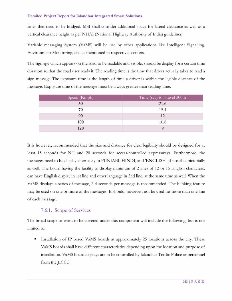
Detailed Project Report for Jalandhar Integrated Smart Solutions
313 | P A G E
lanes that need to be bridged. MSI shall consider additional space for lateral clearance as well as a
vertical clearance height as per NHAI (National Highway Authority of India) guidelines.
Variable messaging System (VaMS) will be use by other applications like Intelligent Signalling,
Environment Monitoring, etc. as mentioned in respective sections.
The sign age which appears on the road to be readable and visible, should be display for a certain time
duration so that the road user reads it. The reading time is the time that driver actually takes to read a
sign message The exposure time is the length of time a driver is within the legible distance of the
message. Exposure time of the message must be always greater than reading time.
Speed (Kmph) Time (sec) to Travel 300m
50 21.6
70 15.4
90 12
100 10.8
120 9
It is however, recommended that the size and distance for clear legibility should be designed for at
least 15 seconds for NH and 20 seconds for access-controlled expressways. Furthermore, the
messages need to be display alternately in PUNJABI, HINDI, and 'ENGLISH', if possible pictorially
as well. The board having the facility to display minimum of 2 lines of 12 or 15 English characters,
can have English display in 1st line and other language in 2nd line, at the same time as well. When the
VaMS displays a series of message, 2-4 seconds per message is recommended. The blinking feature
may be used on one or more of the messages. It should, however, not be used for more than one line
of each message.
7.6.1. Scope of Services
The broad scope of work to be covered under this component will include the following, but is not
limited to:
Installation of IP based VaMS boards at approximately 25 locations across the city. These
VaMS boards shall have different characteristics depending upon the location and purpose of
installation. VaMS board displays are to be controlled by Jalandhar Traffic Police or personnel
from the JICCC.
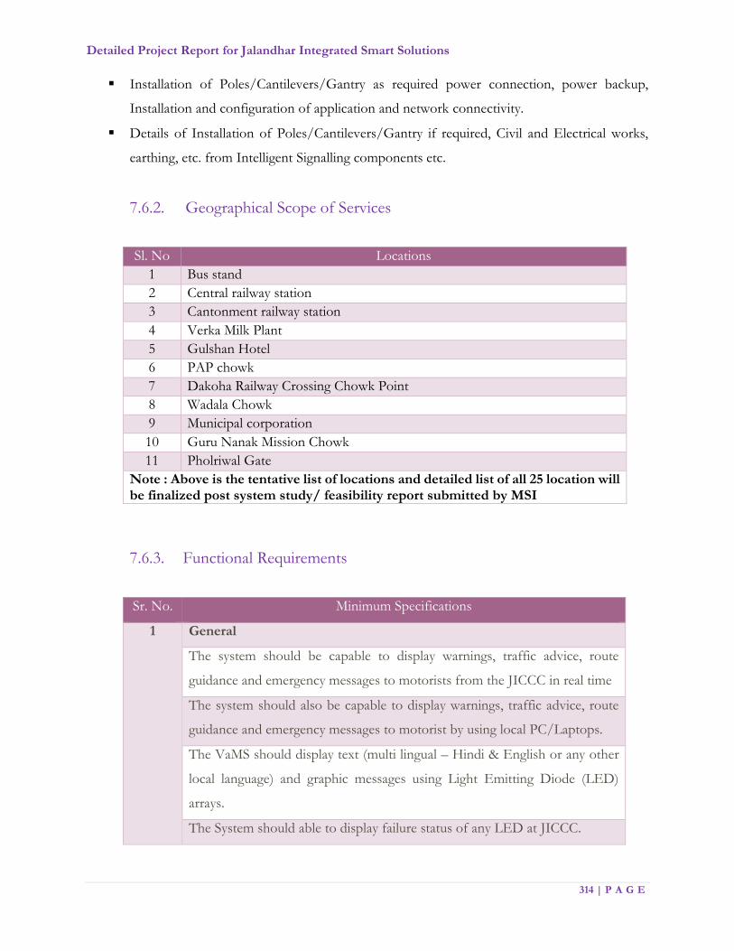
Detailed Project Report for Jalandhar Integrated Smart Solutions
314 | P A G E
Installation of Poles/Cantilevers/Gantry as required power connection, power backup,
Installation and configuration of application and network connectivity.
Details of Installation of Poles/Cantilevers/Gantry if required, Civil and Electrical works,
earthing, etc. from Intelligent Signalling components etc.
7.6.2. Geographical Scope of Services
Sl. No Locations
1 Bus stand
2 Central railway station
3 Cantonment railway station
4 Verka Milk Plant
5 Gulshan Hotel
6 PAP chowk
7 Dakoha Railway Crossing Chowk Point
8 Wadala Chowk
9 Municipal corporation
10 Guru Nanak Mission Chowk
11 Pholriwal Gate
Note : Above is the tentative list of locations and detailed list of all 25 location will be finalized post system study/ feasibility report submitted by MSI
7.6.3. Functional Requirements
Sr. No. Minimum Specifications
1 General
The system should be capable to display warnings, traffic advice, route
guidance and emergency messages to motorists from the JICCC in real time
The system should also be capable to display warnings, traffic advice, route
guidance and emergency messages to motorist by using local PC/Laptops.
The VaMS should display text (multi lingual – Hindi & English or any other
local language) and graphic messages using Light Emitting Diode (LED)
arrays.
The System should able to display failure status of any LED at JICCC.

Detailed Project Report for Jalandhar Integrated Smart Solutions
315 | P A G E
Sr. No. Minimum Specifications
The System should support Display characters in true type fonts and
adjustable based on the Operating system requirement
The VaMS workstation at the JICCC should communicate with the VaMS
controller through the network. It should send out command data to the
variable message sign controller and to confirm normal operation of the
signboard. In return, the VaMS workstation should receive status data from
the VaMS controller.
VaMS controllers should continuously monitor the operation of the VaMS via
the provided communication network.
Operating status of the variable message sign should be checked periodically
from JICCC.
It shall be capable of setting an individual VaMS or group of VaMS’s to display
either one of the pre-set messages or symbols entered into the computer via
the control computer keyboard or by another means.
It shall be capable of being programmed to display an individual message to a
VaMS or a group of VaMS’s at a pre-set date and time.
A sequence of a minimum of 10 messages/pictures/ pre-decided sign or
group of signs shall be possible to assign for individual VaMS or group of
VaMS’s.
It shall also store information about the time log of message displayed on each
VaMS. The information stored shall contain the identification number of the
VaMS, content of the message, date and time at which displayed
message/picture starts and ends.
The central control computer shall perform regular tests (pre-set basis) for
each individual VaMS. Data communication shall be provided with sufficient
security check to avoid unauthorized access
2 Variable Message Sign board application
Central Control Software allows controlling multiple VaMS (up to 20) from
one console.
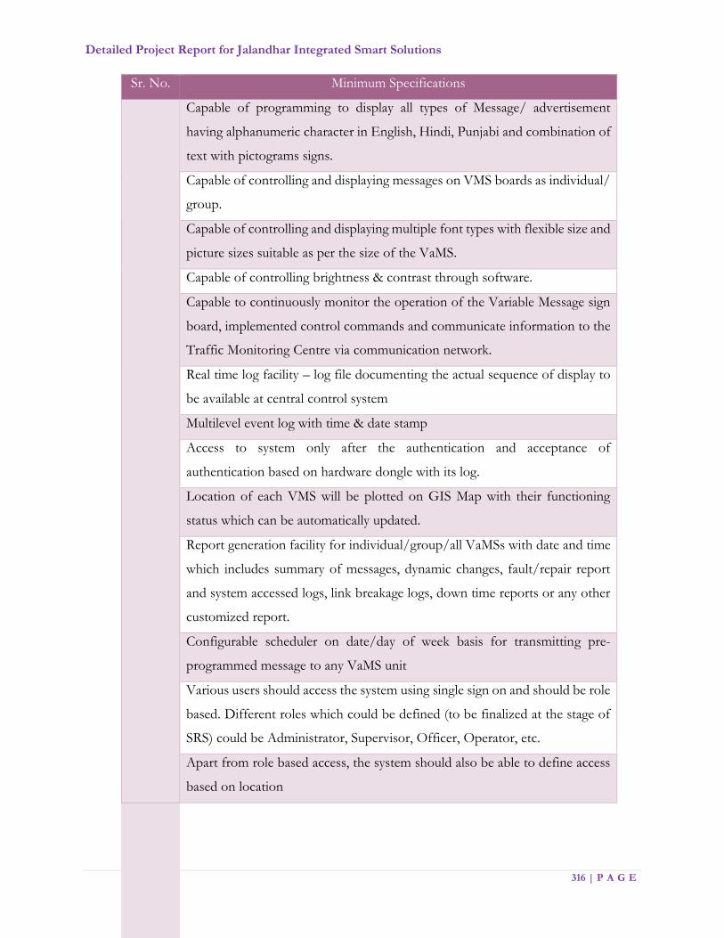
Detailed Project Report for Jalandhar Integrated Smart Solutions
316 | P A G E
Sr. No. Minimum Specifications
Capable of programming to display all types of Message/ advertisement
having alphanumeric character in English, Hindi, Punjabi and combination of
text with pictograms signs.
Capable of controlling and displaying messages on VMS boards as individual/
group.
Capable of controlling and displaying multiple font types with flexible size and
picture sizes suitable as per the size of the VaMS.
Capable of controlling brightness & contrast through software.
Capable to continuously monitor the operation of the Variable Message sign
board, implemented control commands and communicate information to the
Traffic Monitoring Centre via communication network.
Real time log facility – log file documenting the actual sequence of display to
be available at central control system
Multilevel event log with time & date stamp
Access to system only after the authentication and acceptance of
authentication based on hardware dongle with its log.
Location of each VMS will be plotted on GIS Map with their functioning
status which can be automatically updated.
Report generation facility for individual/group/all VaMSs with date and time
which includes summary of messages, dynamic changes, fault/repair report
and system accessed logs, link breakage logs, down time reports or any other
customized report.
Configurable scheduler on date/day of week basis for transmitting pre-
programmed message to any VaMS unit
Various users should access the system using single sign on and should be role
based. Different roles which could be defined (to be finalized at the stage of
SRS) could be Administrator, Supervisor, Officer, Operator, etc.
Apart from role based access, the system should also be able to define access
based on location

Detailed Project Report for Jalandhar Integrated Smart Solutions
317 | P A G E
Sr. No. Minimum Specifications
Rights to different modules / Sub-Modules / Functionalities should be role
based and proper log report should be maintained by the system for such
access
Components of the architecture must provide redundancy and ensure that
there are no single points of failure in the key project components. To take
care of remote failure, the systems need to be configured to mask and recover
with minimum outage.
Ease of configuration, ongoing health monitoring, and failure detection are
vital to the goals of scalability, availability, and security and must be able to
match the growth of the environment.
System shall use open standards and protocols to the extent possible
Facility to export reports to excel and PDF formats.
3 Remote Monitoring
All VaMS shall be connected/configured to Traffic Monitoring Centre for
remote monitoring through network for two-way communication between
VaMS and control Room to check system failure, power failure & link
breakage.
Remote Diagnostics to allow identifying reason of failure up to the level of
failed individual LED.
7.6.4. Technical Specifications
Sl. No. Minimum Specification
1 Dimensions 3.0 mtr length X 1.5 mtr height X 0.2 mtr depth.
(3000mm x 1500mm X 200mm)
2 Colour LED Full Colour, class designation C2 as per IRC/EN
12966
standard
3 Luminance
Class/Ratio
L3 as per IRC/EN 12966 standards
4 Luminance Control & auto Diming

Detailed Project Report for Jalandhar Integrated Smart Solutions
318 | P A G E
a Should be automatically provide different luminance levels but shall also be
controllable from the traffic centre using software
b Auto dimming capability to adjust to ambient light level (sensor based
automatic control)
c Photoelectric sensor shall be positioned at the sign front and sign rear to
measure ambient light. Capable of being continually exposed to direct sunlight
without impairment of performance.
5 Contrast Ratio R3 as per IRC/EN 12966 standard
6 Beam Width B6+ as per IRC/EN12966 standards
7 Pixel Pitch 20mm or better
8 Picture Display
a At least 300mm as per IRC /EN 12966 standards
b Full Matrix: Number of lines & characters adjustable, active area: 2.88mX1.2m
at least
c Synchronized Dot to Dot display.
d Capable of displaying real time, customized messages generated by JICCC.
e Special frontal design to avoid reflection.
f Display shall be UV resistant
9 Viewing Angle B6+ as per IRC/EN12966 standard- Viewing angle
shall ensure message readability for motorists in all
lanes of the approach road
10 Viewing Distance Suitable for readability from 150 Mtrs. or more at the
character size of 240mm, from moving vehicles.
11 a Self-Test
b VMS shall have self-test diagnostic feature to test for correct operation.
c Display driver boards shall test the status of all display cells in the sign even
when diodes are not illuminated.
d All periodic self-test results shall be relayed to the JICCC in real time to
update status of VaMS
12 a Alarms
b Door Open sensor to Inform Control room during unauthorized access
c LED Pixel failure detection alarm
13 Flicker Refresh Frequency should not be less 90 Hz. No
visible flicker to naked eye.
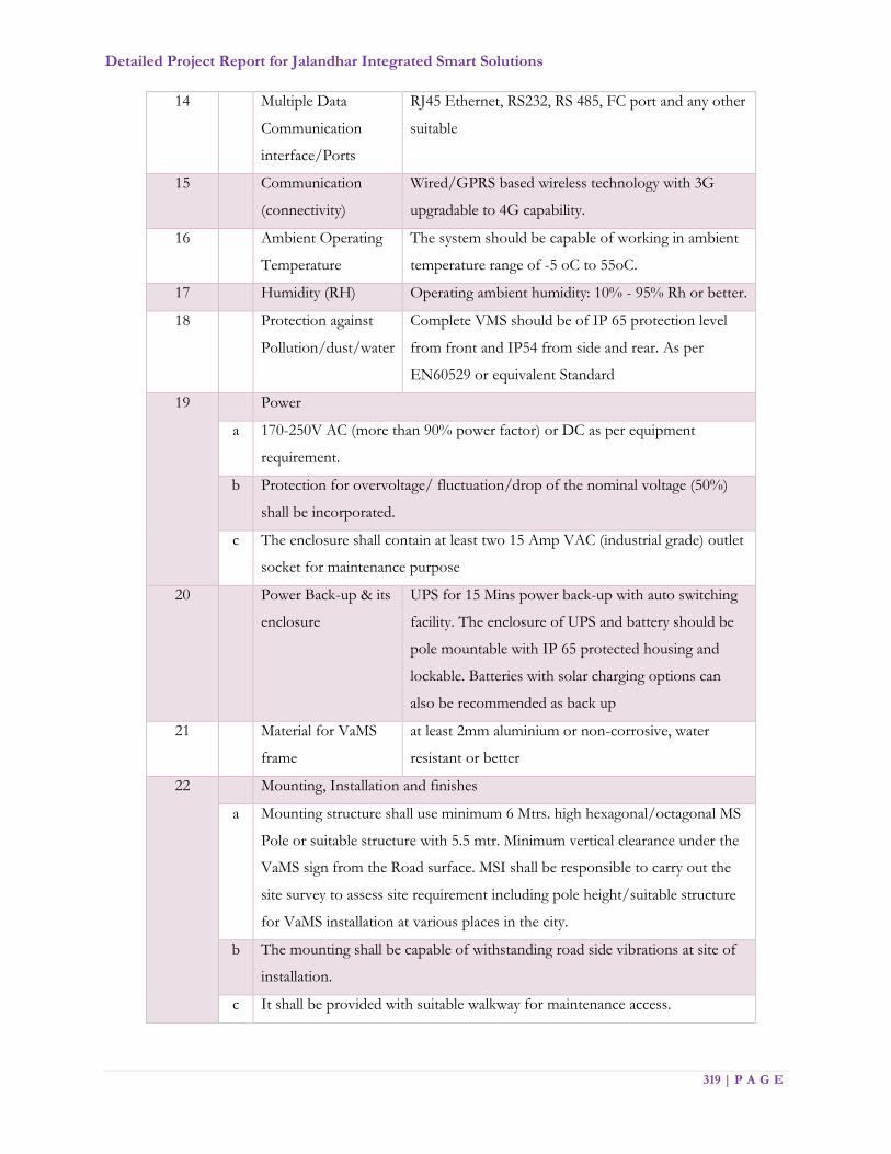
Detailed Project Report for Jalandhar Integrated Smart Solutions
319 | P A G E
14 Multiple Data
Communication
interface/Ports
RJ45 Ethernet, RS232, RS 485, FC port and any other
suitable
15 Communication
(connectivity)
Wired/GPRS based wireless technology with 3G
upgradable to 4G capability.
16 Ambient Operating
Temperature
The system should be capable of working in ambient
temperature range of -5 oC to 55oC.
17 Humidity (RH) Operating ambient humidity: 10% - 95% Rh or better.
18 Protection against
Pollution/dust/water
Complete VMS should be of IP 65 protection level
from front and IP54 from side and rear. As per
EN60529 or equivalent Standard
19 Power
a 170-250V AC (more than 90% power factor) or DC as per equipment
requirement.
b Protection for overvoltage/ fluctuation/drop of the nominal voltage (50%)
shall be incorporated.
c The enclosure shall contain at least two 15 Amp VAC (industrial grade) outlet
socket for maintenance purpose
20 Power Back-up & its
enclosure
UPS for 15 Mins power back-up with auto switching
facility. The enclosure of UPS and battery should be
pole mountable with IP 65 protected housing and
lockable. Batteries with solar charging options can
also be recommended as back up
21 Material for VaMS
frame
at least 2mm aluminium or non-corrosive, water
resistant or better
22 Mounting, Installation and finishes
a Mounting structure shall use minimum 6 Mtrs. high hexagonal/octagonal MS
Pole or suitable structure with 5.5 mtr. Minimum vertical clearance under the
VaMS sign from the Road surface. MSI shall be responsible to carry out the
site survey to assess site requirement including pole height/suitable structure
for VaMS installation at various places in the city.
b The mounting shall be capable of withstanding road side vibrations at site of
installation.
c It shall be provided with suitable walkway for maintenance access.
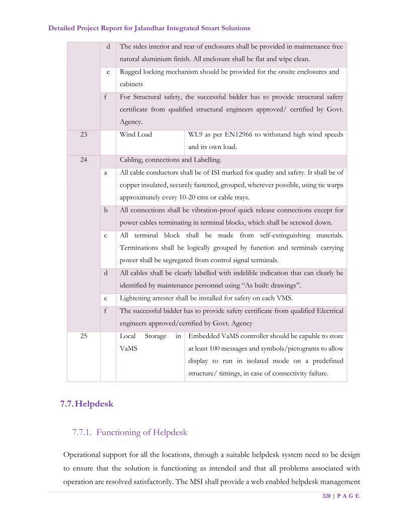
Detailed Project Report for Jalandhar Integrated Smart Solutions
320 | P A G E
d The sides interior and rear of enclosures shall be provided in maintenance free
natural aluminium finish. All enclosure shall be flat and wipe clean.
e Rugged locking mechanism should be provided for the onsite enclosures and
cabinets
f For Structural safety, the successful bidder has to provide structural safety
certificate from qualified structural engineers approved/ certified by Govt.
Agency.
23 Wind Load WL9 as per EN12966 to withstand high wind speeds
and its own load.
24 Cabling, connections and Labelling.
a All cable conductors shall be of ISI marked for quality and safety. It shall be of
copper insulated, securely fastened, grouped, wherever possible, using tie warps
approximately every 10-20 cms or cable trays.
b All connections shall be vibration-proof quick release connections except for
power cables terminating in terminal blocks, which shall be screwed down.
c All terminal block shall be made from self-extinguishing materials.
Terminations shall be logically grouped by function and terminals carrying
power shall be segregated from control signal terminals.
d All cables shall be clearly labelled with indelible indication that can clearly be
identified by maintenance personnel using “As built: drawings”.
e Lightening arrester shall be installed for safety on each VMS.
f The successful bidder has to provide safety certificate from qualified Electrical
engineers approved/certified by Govt. Agency
25 Local Storage in
VaMS
Embedded VaMS controller should be capable to store
at least 100 messages and symbols/pictograms to allow
display to run in isolated mode on a predefined
structure/ timings, in case of connectivity failure.
7.7. Helpdesk
7.7.1. Functioning of Helpdesk
Operational support for all the locations, through a suitable helpdesk system need to be design
to ensure that the solution is functioning as intended and that all problems associated with
operation are resolved satisfactorily. The MSI shall provide a web enabled helpdesk management

Detailed Project Report for Jalandhar Integrated Smart Solutions
321 | P A G E
system with SMS and email based alert system for the Helpdesk Call management and SLA
reporting. MSI shall be required to setup a centralized helpdesk at the Jalandhar Integrated
Command and Control Center (JICCC). The MSI shall be responsible for procurement,
installation, commissioning and operations & maintenance of helpdesk including supply &
installation of IT / Non IT infrastructure along with necessary application software required for
the smooth functioning of the Central Helpdesk at both the location
MSI shall provision for the infrastructure necessary for managing the Help Desk including rent
charges for Toll-free telephone line(s) at the Help Desk location. MSI shall provide multiple
channels to log a complaint such as Toll-free lines, landlines, helpdesk tool, E-mail, direct walk-
in etc. Outage of any component shall be calculate as a time between logging the call and closing
the call.
A helpdesk is envisaged to be provide for the resolution of technical queries by internal users.
Typical helpdesk activities (indicative) shall include, but not limited to:
1. Deployment of sufficient manpower to attend the helpdesk requests for extending technical
support on hardware, network, application etc. to users
2. Deployment of web-based tool for the helpdesk
3. Provide Help Desk facility for agreed SLAs for reporting technical incidents / issues /
problems with the system. Help desk facility shall be provided through Toll-free lines,
landlines, helpdesk tool, E-mail, direct walk-in etc.
4. Implement a call logging system in line with the severity levels as per the SLAs. The Help
desk shall log user calls related to system and assign an incident/ call ID number. Severity
shall be assign to each call as per the SLAs.
5. Track each incident / call to resolution.
6. Escalate the calls, to the appropriate levels, if necessary as per the escalation matrix agreed
upon with JSCL
7. Analyse the incident / call statistics and provide monthly reports including but not limited to:
i. Type of incidents / calls logged
ii. Incidents / calls resolved
iii. Incidents / calls open

Detailed Project Report for Jalandhar Integrated Smart Solutions
322 | P A G E
8. Helpdesk Solution shall further have the capability to upload frequently asked questions
and solutions.
Helpdesk becomes the central collection point for service staff contact and control of the
problem, change, and service management processes. This includes both incident management
and service request management. This shall be the first level of support (L1).
It is also expected that a second level of centralized support (L2) shall also be maintain at the
same location from where the various zones/wards can be serviced in case of problem escalation.
If a problem is not resolve by telephone/help desk tool and the User declares the problem to be
of an emergency nature, MSI shall dispatch a Field Service Staff member who shall provide On-
site Support Service according to service levels given.
The Helpdesk shall act as a single point of contact for all users whether for service requests,
incidents or problems. It shall encompass Helpdesk, Asset Management and Vendor
Management. In addition, it shall offer a focused approach for delivering integrated Service
Management and provide an interface for other functions in IT Services Continuity Management
like Maintenance Contracts, Software Licenses etc.
MSI shall implement effective Helpdesk Management procedures to leverage the knowledge
gained in providing faster and better solutions, create knowledge bases and prevent recurrence
of problems.
7.7.2. Helpdesk Capacity
MSI is required to provide a minimum 8-seater helpdesk at Jalandhar Integrated Command and
Control Center (JICCC) during all operation hours that will be specified in the BID
DOCUMENT. However, if the MSI believes that in order to meet the SLAs, additional capacity
is required, the same may be provide by the MSI. It is also to be noted that, any supervisors
required for the Helpdesk Operators shall be over and above the minimum operators mentioned.
7.7.3. Manpower requirement
The MSI is required to provide defined number of Operators at Helpdesk for operating and
managing the Helpdesk, which will be mention in BID DOCUMENT. The Operators shall
perform various activities including:

Detailed Project Report for Jalandhar Integrated Smart Solutions
323 | P A G E
a. Understanding the query/issue in the reported request. Query could be related to the
following:
o Hardware including issues related to desktop/laptop, printer/multi-function
device, local server, routers/switches
o Application including login and password issues, accessing a particular module,
navigation assistance, report generation assistance
o Network including internet/intranet and end-user device connectivity
b. Providing information / clarification on the spot in case of an informational query or
providing necessary troubleshooting assistance in case of a logged issue
c. In case of technical issues for which a resolution is not possible instantly, the operator
shall submit the request into the system for escalation and further action by the MSI’s
team
d. Process all service requests, dispatch them to field personnel who shall perform the
follow up
Field Support Staff
The MSI is required to provide Field Support Staff for undertaking all activities on field to
complete a call logged by a User. MSI is expected to deploy enough number of Field Support
Staff to ensure that SLAs which will be mentioned in BID DOCUMENT.
7.7.4. Function Requirements of Help Desk Operations
Automated Call Distribution Software
ACD system (Hardware & Software) shall be provided in 1:1 Hot Standby
configuration.
The ACD system shall be able to handle call & IP Phone capacity defined.
System should support skill base routing, multiple group support, priority handling
and Queue status indicator. It is desirable that calls to certain trunk groups or to
certain dialled numbers be assigned a higher priority than other calls and that calls
which overflow from another split be queued ahead of other calls.
System should support 50 (Fifty) call center agents on a single server

Detailed Project Report for Jalandhar Integrated Smart Solutions
324 | P A G E
Single system should be able to administer 100 (hundred) agents
Call overflow: The system should support call overflow routing e.g. if there is a queue
in particular ACD group and another group is sitting idle, system should be able to
transfer the calls to another group based on the settings defined by the
administrator.
Skill Assignment and Preference Levels: The proposed system must be able to assign
individual skills to each call taker/agent (i.e. Bilingual, training or experience
level, product knowledge, customer knowledge, etc.). Individually assigned skills
must be able to be ranked and rated in terms of priority, proficiency or preference.
Virtual Seating or Free Seating - The proposed system must support the concept of
virtual seating. Call takers/agents can log-on from any "soft phone" instrument
within the system. Call takers/agents on the proposed system will be logically
defined, rather than requiring a "soft phone" extension and termination. Each Call
taker/agent and supervisor on the system must have an individually assigned log- on
identification number, which permits individual statistics to be collected by the ACD
management information system. Multiple log-on events by the same individual
during a work period at different terminals must be tracked individually as one
"shift".
The system should support assigning multiple skill sets (minimum 120) to an agent
without degradation of the overall system capacity.
Route calls to remote call centres based on agent skill availability.
Prioritized call routing — It shall be possible to define Agent Preference options
ACD System should be able to support integrated self-service applications.
ACD System should be able to run defined workflow via HTTP request.
In addition to the above, The ACD system should have the following features:
o Expert Agent Selection (EAS)
o Expert Agent Selection – Preference Handling Distribution (EAD-PHD)
o Least Occupied Agent (LOA)
o Reason Codes for AUX Work & Log-Off
o Skill Level and Expert Agent Distribution
o ISDN Network Call Redirection (NCR)
o Service Observe of Logical Agent
o Service Level Maximizer (SLM)

Detailed Project Report for Jalandhar Integrated Smart Solutions
325 | P A G E
o Forced Agent Logout from ACW
o ASA (Average Speed of Answer) Routing
The offered voice system should have an integrated call center functionality, both IP
and non-IP and It should also support both IP and non-IP agents simultaneously
The system should support load balancing of calls among multiple ACDs.
The offered system should redirect unanswered calls.
Offered system should support to provide the capability to the supervisors for logout
agents from their own voice terminal without having to go to the agent’s desk & it
could be possible from a remote location.
The proposed system should support a multisite call center environment with
multiple distinct sites as a single virtual call center operation. It should also have a
capability to allocated call between sites based upon agent skills, agent availability,
queue times, and other criteria.
The offered ACD system should be able to collect request information, such as a zip
code or account code, before the call is sent to an agent and then route the call based
upon that information.
Proposed system could use the estimated wait time or average speed of answer to
make routing decisions.
The offered system should predict the estimated wait time for various split/skills and
pick the best destination for a call to avoid excessive wait times and subsequent
overflow. It should support predictive wait time routing
Call routing program have a capability to connect the caller to an Interactive Voice
Response (IVR) system while the call remains in queue for an agent. The incoming
call should not lose its place in queue when the call is routed to voice applications,
audio text announcements, or other IVR applications.
The system should promote agent fairness relative to equitable agent call distribution
for multi-skilled agents. The system should be able to distribute calls to agents based
on ACD work occupancy instead of idlest or longest current idle time.
Both agents and supervisors should be notified via the telephone indicators when
thresholds are reached for individuals and groups.
The offered system should have a capability for agents to record personalized
greetings that can be played to the caller prior to connection to the agent.

Detailed Project Report for Jalandhar Integrated Smart Solutions
326 | P A G E
The offered system should support for service level call routing. Like for each call
type in terms of “answer X% of this type of calls within Y seconds” and will your
ACD routing algorithms use our specified X & Y service level factors to route and
deliver specific calls accordingly to meet the specified objectives.
CTI - Computer Telephony Integration Software
The CTI shall be provided with 1:1 Hot Standby configuration to avoid any single
point of failure.
The CTI system shall be able to handle call & IP Phone capacity defined above.
The CTI platform shall be able to provide the caller’s CLI information. It shall be
possible to send & populate agent’s PC with CLI information.
The offered CTI platform shall support a set of APIs.
The CTI link shall be able to pass events and information of agent states and changes
in agent states as well as incoming calls to the computer applications, e.g., if the
customer calls from the same no. from which he had called earlier
(registered/unregistered), the CTI platform shall be able to automatically fetch and
display at least last 5 service requests details for that customer.
The CTI shall maintain the accounting and authorization logs of the users accessing
the components of the telephony system. The logs shall include information users
who have logged-in into the system and the specific commands entered by them.
It shall have web-based GUI console for administration, configuration &
management of the system, Real-time information/alerts and reports regarding
health status e.g. up/down status, performance & resource utilization statistics etc.
of the system shall be available through this console.
Voice Recording System for Agent Calls - Softphone Software
Recording:
The call recording solution (Hardware & Software) shall be provided in hot standby
configuration.
The solution must be able to record IP phone communication via the LAN, without
employing a passive or active IP sniffing on the network.
Detailed Project Report for Jalandhar Integrated Smart Solutions
327 | P A G E
The recording solution must provide a single universal license that can support
recording on all phones including analog phone, digital phone, IP phone, IP soft-
phone.
The solution must be able to record encrypted IP phone communication via the
LAN.
The solution should also be able to record IP, Digital & analog endpoints
Should record inbound ACD calls and outbound dialler calls.
Should be able to support Master-Slave configuration in case of large deployments
support for Centralized or decentralized search and replay of calls
"Tag" or classify calls with user-defined labels for simplified search and replay
Quality Recording:
The solution shall provide scalable screen recording.
The solution should allow for voice only, data only, or voice and data recording based
on specific event triggers.
The solution should support selective recording based upon user-defined business
rules
The solution should have the capability to record based on a particular schedule (for
example, record all calls on Tuesday from 9:00 - 11:00 AM for agent XYZ).
The system should show the status of the agents; which agents are logged on.
The solution should allow for the automatic refresh of the logged on agent display.
The solution should be able to provide real-time agent monitoring.
The solution should provide an optional desktop application to allow agents to
initiate and /or terminate recording (Record on Demand)
System should support Rules-based recording
Reporting:
Standard out-of-the-box reports generation should be possible.
The system should be able to customize the reports
The reporting system shall be part of an industry standard platform, or it should be
a propriety product.
Detailed Project Report for Jalandhar Integrated Smart Solutions
328 | P A G E
Reports should be scheduled for automatic delivery to email or a file directory.
Both text and graph reports shall be offered.
Evaluation of Agents (scoring)
This should include adding questions, changing weightings and changing values.
Evaluate multimedia calls and application use
The solution should allow the user to create, without vendor customization, multiple
grading templates using questions provided by the user.
The solution should have the capability of inserting notes on a per-question basis
and a summary note into the grading form.
Easy to create evaluation forms
Recording supported for wide range of contact center needs including inbound and
outbound calls, phone, email and web chat
The solution should produce scorecards with multiple Key Performance Indicators
(KPIs).
The solution should be able to show trends based on historical performance.
Individual scorecards should give an overview of individual agent performance,
supervisor group performance, manager’s group’s performance, overall contact
center(s) performance and enterprise contact center performance.
Analytics:
It should be able to integrate other forms of metadata.
The system should be able to be extended to include additional metadata.
The data should be stored in an industry standard, non-proprietary format.
It should support encrypted audio.
IP Phone - Softphone Software
The IP phones should be of the same make as that of IP PBX supplied by MSI.
The IP Phone shall have an interactive and user-friendly alphanumeric display to
make use of the key phone very simple.
The IP Phones shall support connection of Headset.
The IP Phone shall have LED/LCD Indicator for Call Waiting and Message Waiting.
It shall be possible to set preferences such as Display Contrast and Ring Types.

Detailed Project Report for Jalandhar Integrated Smart Solutions
329 | P A G E
Voice Broadcasting Software.
This may be the integral part of CAD software or Master System Integrator (MSI) may
purchase the separate tool as per the below mentioned requirement and later integrate with
CAD solution
Broadcasting (BOLOs)
1 BOLOs should be sent to:
Any CAD workstation/terminal
Any personnel by name
Groups of personnel by name, unit and/or terminal
All units on a specified event
Combinations of the above
2 Should have ability to associate a BOLO to an Event number
3 Should have association of the BOLO to an Event number results in the automatic
population of the location information in the Broadcast dialog
4 Should have ability to associate a BOLO to a case number
5 BOLOs should be created without relating to an event
6 Should have ability to create a Broadcast (BOLO) in association with an event and
place the event in a Held status in one function
Telephony System (IP PBX System and Gateway) - Answering Service Software
It should be possible for the IP phone to be connected on the same line which is
connected to the computer i.e. Single wire to desk.
The system software version offered should be the latest release as on the date of
supply of EPABX as available globally.
The call processing, Signalling & networking components of the offered system shall
be based on open standards.
The system architecture should allow for incremental application additions to the
enterprise without modification to existing feature server software
The PBX shall be provided in 1:1 Hot Standby mode to avoid any single point of
failure. The PBX servers shall work in 1:1 Hot standby configuration in such a
manner that if one server fails the second server is able to take the complete load of
calls automatically (without any manual intervention) without dropping any existing
calls (IP, TDM & PRI).
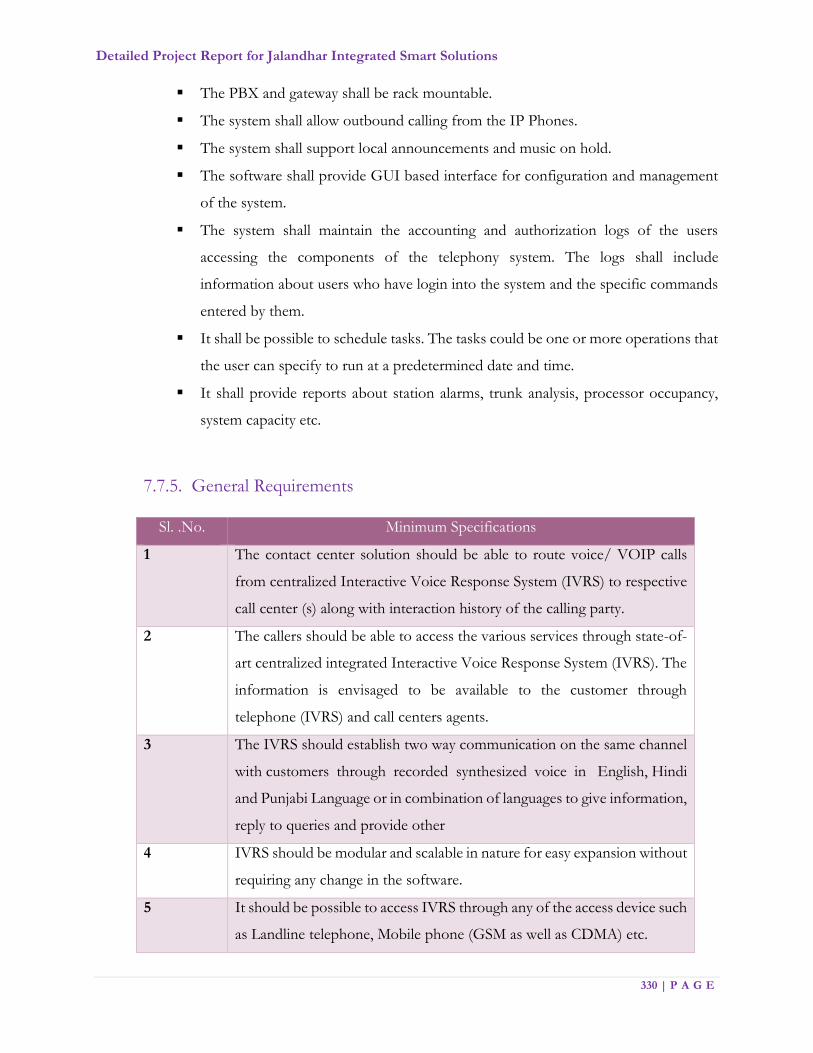
Detailed Project Report for Jalandhar Integrated Smart Solutions
330 | P A G E
The PBX and gateway shall be rack mountable.
The system shall allow outbound calling from the IP Phones.
The system shall support local announcements and music on hold.
The software shall provide GUI based interface for configuration and management
of the system.
The system shall maintain the accounting and authorization logs of the users
accessing the components of the telephony system. The logs shall include
information about users who have login into the system and the specific commands
entered by them.
It shall be possible to schedule tasks. The tasks could be one or more operations that
the user can specify to run at a predetermined date and time.
It shall provide reports about station alarms, trunk analysis, processor occupancy,
system capacity etc.
7.7.5. General Requirements
Sl. .No. Minimum Specifications
1 The contact center solution should be able to route voice/ VOIP calls
from centralized Interactive Voice Response System (IVRS) to respective
call center (s) along with interaction history of the calling party.
2 The callers should be able to access the various services through state-of-
art centralized integrated Interactive Voice Response System (IVRS). The
information is envisaged to be available to the customer through
telephone (IVRS) and call centers agents.
3 The IVRS should establish two way communication on the same channel
with customers through recorded synthesized voice in English, Hindi
and Punjabi Language or in combination of languages to give information,
reply to queries and provide other
4 IVRS should be modular and scalable in nature for easy expansion without
requiring any change in the software.
5 It should be possible to access IVRS through any of the access device such
as Landline telephone, Mobile phone (GSM as well as CDMA) etc.
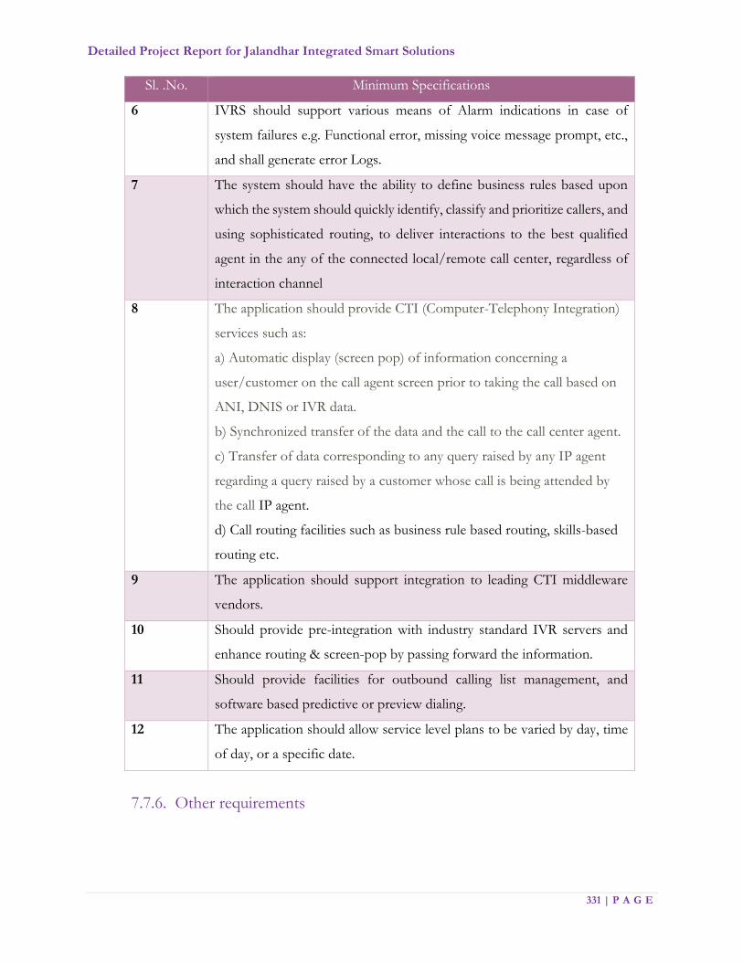
Detailed Project Report for Jalandhar Integrated Smart Solutions
331 | P A G E
Sl. .No. Minimum Specifications
6 IVRS should support various means of Alarm indications in case of
system failures e.g. Functional error, missing voice message prompt, etc.,
and shall generate error Logs.
7 The system should have the ability to define business rules based upon
which the system should quickly identify, classify and prioritize callers, and
using sophisticated routing, to deliver interactions to the best qualified
agent in the any of the connected local/remote call center, regardless of
interaction channel
8 The application should provide CTI (Computer-Telephony Integration)
services such as:
a) Automatic display (screen pop) of information concerning a
user/customer on the call agent screen prior to taking the call based on
ANI, DNIS or IVR data.
b) Synchronized transfer of the data and the call to the call center agent.
c) Transfer of data corresponding to any query raised by any IP agent
regarding a query raised by a customer whose call is being attended by
the call IP agent.
d) Call routing facilities such as business rule based routing, skills-based
routing etc.
9 The application should support integration to leading CTI middleware
vendors.
10 Should provide pre-integration with industry standard IVR servers and
enhance routing & screen-pop by passing forward the information.
11 Should provide facilities for outbound calling list management, and
software based predictive or preview dialing.
12 The application should allow service level plans to be varied by day, time
of day, or a specific date.
7.7.6. Other requirements

Detailed Project Report for Jalandhar Integrated Smart Solutions
332 | P A G E
Sl. No. Minimum Specifications
1 It should provide consistent user interface across multiple media types like fax,
SMS, telephone, email, and web call back.
2 The executive’s desktop should have a “soft-phone” – an application that
enables standard telephony functions through a GUI.
3 It should provide the executives with a help-desk functionality to guide them
to answer a specific query intelligently.
4 It should also provide an easy access to executives to previous similar query
which was answered successfully.
5 It should also be possible to identify a request to be a similar request made
earlier.
6 It should be possible for executives to mark a query as complex/typical and put
in to database for future reference by other agents.
7 It should be possible for executives to escalate the query.
8 System should be able to integrate with e–mail / SMS gateway so that
appropriate messages can be sent to the relevant stakeholders after the
interaction and any updates thereon.
9 Should intelligently and automatically responds to email inquiries or routes
inquires with skills based routing discipline to agents.
7.8. Geographic Information System (GIS)
One of the goals of the smart city initiative is to create a single citizen interface where all data and
applications are available on a GIS platform. An initial effort was conduct by Municipal Corporation
to create the GIS database. As part of smart city initiative, a full-fledged GIS infrastructure has to be
established as part of JICCC and use the existing geodatabase with the following features:
Use City level GIS platform, infrastructure & application as a foundation for Smart City
solution, City Operation Center & Command & Control Center
Collaboration of various city stakeholders & departments together and to have a connect and
engagement via a common GIS window for all operations
Use GIS as spatial planning and analysis for various operation within city
Use GIS as a Decision support system to prioritize actions
To have a location based services to citizens of cities for better transparency & quick actions
Detailed Project Report for Jalandhar Integrated Smart Solutions
333 | P A G E
GIS based spatial and non-spatial queries for citizens and administrators and departmental
stakeholders
Provide administrators, citizens, tourists, businesses real time, and actionable information to
aid their day-to-day decision-making
There shall be a separate RFP which will be floated to have a Project Management Unit for
creating geodatabase for Jalandhar city,
The broad scope of RFP shall be:
Identify the GIS layers with required attributes for day to day operations of each of the
project component
Collection of required GIS/CAD data from various line departments and conversion to
GIS ready format
Mapping of ICT related information for Smart city assets with detailed attribute details
Provide all the required GIS data in standard format for Application Development
To provide necessary API/Inputs to MSI to integrate various citywide applications
Creation GIS data layers on GIS Map

Detailed Project Report for Jalandhar Integrated Smart Solutions
334 | P A G E
The existing details of GIS infrastructure is as follows:
GIS database Creation
The PMU team will create standard data formats in coordination with stakeholders and will
update the data layers as required to develop smart city specific GIS database. The PMU team
will develop the GIS application for city using the data provided.
PMU team will be responsible to collect the required data from concerned departments. The
PMU team is also responsible for data layer creation or mapping of ICT related assets and sensor
systems (like locations of streetlight poles, CCTV cameras, utilities, Smart bus shelters,
environment sensors etc.). If this requires field survey, it needs to be done by PMU team. The
TS Data Layers Sec-1 Sec-2 Sec-3 Sec-4 Sec-5 Sec-6 Sec-7 Sec-8 Sec-9 Sec-10 Sec-11 Sec-12 Sec-13 Sec-14 Sec-15 Sec-16 Sec-17 Sec-18 Sec-19 Sec-20
Bank
Box
Bridges and Flyover
Bus Stand
Canal
Carriage Way
DGPS
Dispensary
Drainage
Dustbin
EB Poles
Electricity Poles
Electric Line
Fire Brigade
Footpath
Garbage Point
Hospital
Key Institutions
Land Marks
Manholes
Mobile Towers
OFC
OHSR
Open Plot
Overhead Water Tank
Parks
Police Stations
Post Office
Railway Line
Road Centreline
School/College
Sector Boundary
Sreet Light
Telephone Poles
Temple_Mosque
Tree
Toilet
Traffic Signals
Transformers
Vent Pipe
Water Tap
Zonal Office
Legend
Data/Layer Not Available
Available
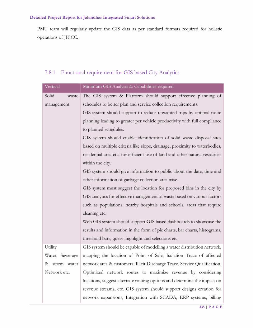
Detailed Project Report for Jalandhar Integrated Smart Solutions
335 | P A G E
PMU team will regularly update the GIS data as per standard formats required for holistic
operations of JICCC.
7.8.1. Functional requirement for GIS based City Analytics
Vertical Minimum GIS Analysis & Capabilities required
Solid waste
management
The GIS system & Platform should support effective planning of
schedules to better plan and service collection requirements.
GIS system should support to reduce unwanted trips by optimal route
planning leading to greater per vehicle productivity with full compliance
to planned schedules.
GIS system should enable identification of solid waste disposal sites
based on multiple criteria like slope, drainage, proximity to waterbodies,
residential area etc. for efficient use of land and other natural resources
within the city.
GIS system should give information to public about the date, time and
other information of garbage collection area wise.
GIS system must suggest the location for proposed bins in the city by
GIS analytics for effective management of waste based on various factors
such as populations, nearby hospitals and schools, areas that require
cleaning etc.
Web GIS system should support GIS based dashboards to showcase the
results and information in the form of pie charts, bar charts, histograms,
threshold bars, query ,highlight and selections etc.
Utility
Water, Sewerage
& storm water
Network etc.
GIS system should be capable of modelling a water distribution network,
mapping the location of Point of Sale, Isolation Trace of affected
network area & customers, Illicit Discharge Trace, Service Qualification,
Optimized network routes to maximize revenue by considering
locations, suggest alternate routing options and determine the impact on
revenue streams, etc. GIS system should support designs creation for
network expansions, Integration with SCADA, ERP systems, billing

Detailed Project Report for Jalandhar Integrated Smart Solutions
336 | P A G E
Vertical Minimum GIS Analysis & Capabilities required
system, Metering system (smart meters), 3rd party Network Management
systems for specific spatial analysis.
The GIS system should be easily configurable to meet specific
requirements like Network isolation Trace, Service Qualification etc.
without having to build them from scratch, and with the assurance of
following best practices, and capable of extending based on
requirements. GIS system must have operational dashboards that
dynamically linked to the water asset information’s & gives the entire
status of O&M.
GIS system to perform the sewerage network tracing, Manhole
inspection, Monitoring – preventive maintenance, field crew navigation
applications, field survey application and reports for repairs etc.
Environmental
Sensors / Air
Quality
Monitoring
GIS system should support to spatially map the air quality data, following
statistical analysis to predict the values associated with spatial or
spatiotemporal phenomena Primarily for environmental sensor reading
analysis in order to decide if they pose a threat to environmental or
human health and warrant remediation. GIS system should be capable of
using proven deterministic methods of statistical Analysis to calculate
unknown values of air quality: Inverse distance weighted, local
polynomial, global polynomial, radial basis functions etc.
The techniques should help to quantify the spatial autocorrelation among
measured points and account for the spatial configuration of the sample
points around the prediction location. GIS System should be capable to
make a prediction— From the kriging weights for the measured values,
calculate a prediction for the location with the unknown value.
GIS system should be capable of accounting the error introduced by
estimating the semivariogram model, by using many semivariogram
models rather than a single semivariogram. It should be able to identify
trends in the cluster of point densities to spatially locate the new,
consecutive, intensifying, persistent, diminishing, sporadic, oscillating

Detailed Project Report for Jalandhar Integrated Smart Solutions
337 | P A G E
Vertical Minimum GIS Analysis & Capabilities required
and historical hot and cold spots based on “Getis-Ord Gi” statistic P-
Value & Z-Score for each feature in a dataset.
GIS system based on the location analytics must find the areas that are
causing the pollution like nearby industries and identifies the open green
spaces where plantation can be improved for pollution reduction.
Provision for
Property Tax and
Land
management
Property Tax /Land administration platform should seamlessly integrate
with field operations and should securely connect to disparate systems to
maintain the integrity of survey data. This GIS platform should support
in creating and maintaining cadastral data and should streamline work
processes and speeds the enrolment of new parcels including Tax Parcel
editing including the tools, workflow, topology, error checking, version
management, and historic rollback that make mapping and public records
tasks quick and easy. It should be able to identify GIS tax data errors
based on set of rules and behaviours that model how points, lines, and
polygons share coincident geometry.
Support field data collection to collect data against a map or form-based
data and integration with Enterprise cadastral system and track tax
payment status per plot.
Intelligent Traffic
System, Routing
& ICT for City
bus services
It should help to maintain inventory of assets (roads, buildings, bridges
etc.) along with asset details and condition data. It should support
assigning and editing network features such as barriers, turns and uni-
directional flow and should provide Multipoint routing ability. A network
dataset is capable of modelling a single mode of transportation, 3D and
Multimodal network datasets. The GIS system should help to track the
location on real-time, in scheduling and determining the optimum
number of vehicles required on the road, and optimal routing tools for
multiple vehicles to reduce fuel consumption and therefore create a
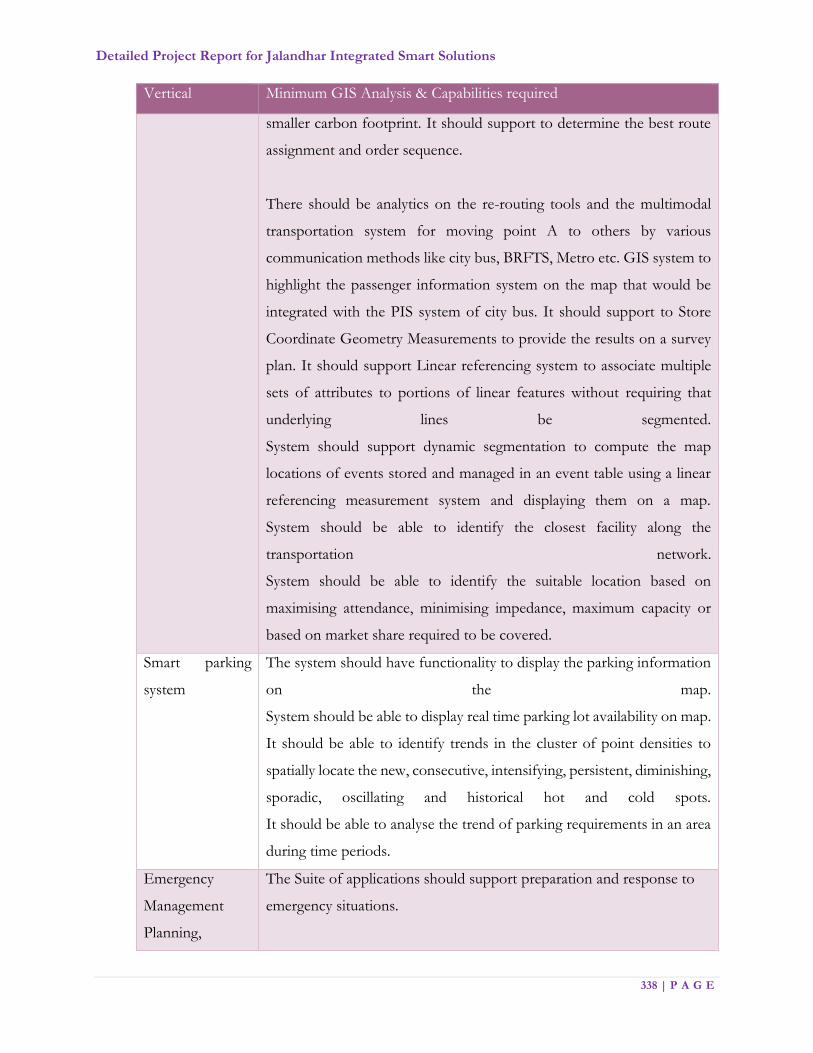
Detailed Project Report for Jalandhar Integrated Smart Solutions
338 | P A G E
Vertical Minimum GIS Analysis & Capabilities required
smaller carbon footprint. It should support to determine the best route
assignment and order sequence.
There should be analytics on the re-routing tools and the multimodal
transportation system for moving point A to others by various
communication methods like city bus, BRFTS, Metro etc. GIS system to
highlight the passenger information system on the map that would be
integrated with the PIS system of city bus. It should support to Store
Coordinate Geometry Measurements to provide the results on a survey
plan. It should support Linear referencing system to associate multiple
sets of attributes to portions of linear features without requiring that
underlying lines be segmented.
System should support dynamic segmentation to compute the map
locations of events stored and managed in an event table using a linear
referencing measurement system and displaying them on a map.
System should be able to identify the closest facility along the
transportation network.
System should be able to identify the suitable location based on
maximising attendance, minimising impedance, maximum capacity or
based on market share required to be covered.
Smart parking
system
The system should have functionality to display the parking information
on the map.
System should be able to display real time parking lot availability on map.
It should be able to identify trends in the cluster of point densities to
spatially locate the new, consecutive, intensifying, persistent, diminishing,
sporadic, oscillating and historical hot and cold spots.
It should be able to analyse the trend of parking requirements in an area
during time periods.
Emergency
Management
Planning,
The Suite of applications should support preparation and response to
emergency situations.
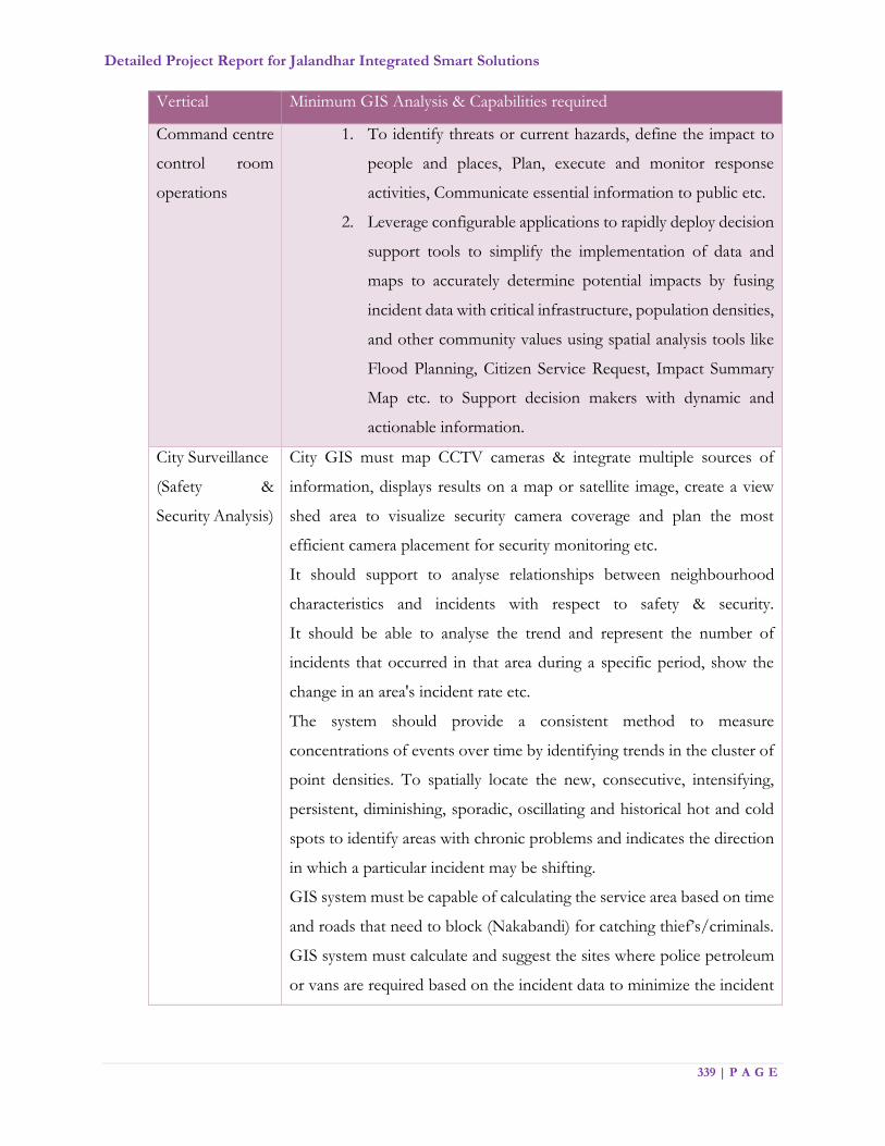
Detailed Project Report for Jalandhar Integrated Smart Solutions
339 | P A G E
Vertical Minimum GIS Analysis & Capabilities required
Command centre
control room
operations
1. To identify threats or current hazards, define the impact to
people and places, Plan, execute and monitor response
activities, Communicate essential information to public etc.
2. Leverage configurable applications to rapidly deploy decision
support tools to simplify the implementation of data and
maps to accurately determine potential impacts by fusing
incident data with critical infrastructure, population densities,
and other community values using spatial analysis tools like
Flood Planning, Citizen Service Request, Impact Summary
Map etc. to Support decision makers with dynamic and
actionable information.
City Surveillance
(Safety &
Security Analysis)
City GIS must map CCTV cameras & integrate multiple sources of
information, displays results on a map or satellite image, create a view
shed area to visualize security camera coverage and plan the most
efficient camera placement for security monitoring etc.
It should support to analyse relationships between neighbourhood
characteristics and incidents with respect to safety & security.
It should be able to analyse the trend and represent the number of
incidents that occurred in that area during a specific period, show the
change in an area's incident rate etc.
The system should provide a consistent method to measure
concentrations of events over time by identifying trends in the cluster of
point densities. To spatially locate the new, consecutive, intensifying,
persistent, diminishing, sporadic, oscillating and historical hot and cold
spots to identify areas with chronic problems and indicates the direction
in which a particular incident may be shifting.
GIS system must be capable of calculating the service area based on time
and roads that need to block (Nakabandi) for catching thief’s/criminals.
GIS system must calculate and suggest the sites where police petroleum
or vans are required based on the incident data to minimize the incident
Detailed Project Report for Jalandhar Integrated Smart Solutions
340 | P A G E
Vertical Minimum GIS Analysis & Capabilities required
activities in the city. GIS System should be capable of maintaining data
history, version management and conflict detection.
7.8.2. Integration of GIS Maps with Smart City Elements
MSI would analyse the integration of all mentioned Smart elements with Jalandhar GIS maps and
provide operations that help achieve KPI’s mentioned for each of the Smart elements. MSI should
conduct analysis of integration points and provide a detailed report and get approval from JSCL
before integration. It should also include the layers of the utility departments which are already
existing with MCJ. MSI is responsible to work with the previous vendor to get the GIS Maps and
integrate (Geo tagging, Geo fencing etc.) with Smart elements. JSCL will help MSI get the details
from each line department and facilitate to get the required information on time. MSI shall develop
operational procedures using GIS Map Interface.
GIS Map will be provided by JSCL on ArcGIS for integration. Following are the objectives from
the GIS Integration.
1. GIS Map should be used as a common platform across all the solutions including
Smart parking, Environmental, Sensors Monitoring, Intelligent Traffic Management,
E-Governance, Utility Management system, Public Transport, Police Vehicles etc.
2. Appropriate geo referencing & geo tagging on the map should be done covering all
relevant Smart elements in BID DOCUMENT and various POI’s such as public
amenities, bus stops, bus routes, bin locations, transfer stations, street poles etc.
3. The component mapping should be multi layered keeping in vision the requirements
for next 20 years.
4. GIS data modal need to be designed in accordance with Smart City solutions and need
to be scalable and robust in nature so that it can meet any future need of smart solution
and integration with future smart solutions and modules of city.
5. Alert, Events, Statuses for each smart element including hardware and software should
be displayed on GIS Map.
6. The related Smart elements like Variable messaging system (VaMS) should also be
displayed in the same layer for the application. Ex: Traffic Management,
Environmental monitoring.
Detailed Project Report for Jalandhar Integrated Smart Solutions
341 | P A G E
7. All government buildings and spaces should be geo tagged for the City of Jalandhar
and shall be capable of data analytics based on GIS base map updates.
8. GIS data modal integrated should support domains, subtype, spatial rules and
relationship, joins and spatial references etc.
9. GIS catalogue should be used to manage and maintain the GIS data modal. It must
support database administration for user creation and management for GIS database.
10. City Level GIS Portal: GIS Web will include city portal for as a single window for
accessing all the location based information. For more details, please refer e-
governance section of DPR
11. Department specific search & query module should produce relevant output.
12. GIS maps must be integrated with GPS devices to locate real time position on GIS
map & provide optimal route mapping.
13. SWM Assets mapping on GIS such as bins, transfer stations, landfill, garbage
collection sites etc. Authority will provide SWM department related data.
14. There must be various analysis and work operations for Solid waste management from
GIS application such as Geo fencing of waste bins, Geo fencing of vehicles, locate
bins and bins location, signals, CCTV Surveillance cameras and provide planning &
route optimization.
7.9. Disaster Management
MSI has to provide a separate module for Disaster Management solution. The Disaster
Management module should be able to collect gather and analyse the critical data of city from
various components. The system should be able to create a strategic view or big picture of
probable disaster. The system should be intelligent enough to make decisions that protect life
and property. The system should disseminate such decisions to all concerned agencies and
individuals. The critical data elements may be decided in consultation with JSCL. The system
should be able to use predictive analysis which can finally reduce response time and improve
SLAs. Disaster Management module should be able to communicate or to be integrated with
National Emergency Operation Centre (NEOC) of National Disaster Response Force
(NDRF) based on defined SOPs. The Disaster Management system should be in compliance
to applicable laws. The Disaster management module should have interoperability between
cities, here it refers that disaster management module of any city should be able to cater the

Detailed Project Report for Jalandhar Integrated Smart Solutions
342 | P A G E
disaster management operation of any of the other cities as applicable. Standard Operating
Procedures (SoP’s) must adhere with the Governance structure of JSCL and Municipal
Corporations, as in case of any incident or disaster decision making ability lies with JSCL.
7.10. Jalandhar Environmental Monitoring System (JEMS)
Environmental pollution, particularly of the air, is nowadays a major problem that unknowingly
affects lives in the cities. As clear focus of building [city] as one of the finest example of SMART
city, JSCL believes it is important that citizens know of the air that they breathe. Citizens & visitors
to City can enjoy unique experiences that keep them feeling good by knowing city’s environment
condition at different locations.
The Air quality should be monitored by a network comprising:
Fixed monitoring stations
Data processing
Data transmission to a central system
A central processing system
7.10.1. KPIs for Environmental Monitoring System
1. Provide better quality air to citizens of Jalandhar
2. Monitor environment pollution and have measures to control pollution
3. Environmental monitoring to be implemented in all major parts of the city
especially in crowded places
4. Environmental monitoring should consist of measuring levels for Temperature,
Humidity, Ambient Light, Sound, Pressure, CO, CO2, NO2, O2, SO2 and
compulsorily PM 2.5 and PM 10.
5. Integrate with other disaster management applications from other nodal
organizations of environment
6. Additional monitoring will be done in crowded areas of Jalandhar
7. Environment monitoring sensors will be installed dump yards and solid waste
management locations and crowded areas of Jalandhar

Detailed Project Report for Jalandhar Integrated Smart Solutions
343 | P A G E
7.10.2. Scope of work
As part of scope of work, MSI need to perform the below mentioned activities.
1. Install minimum of 5 environment sensors (as per the functional requirement) &
display environment related information at various strategic locations through variable
message system (VaMS)
2. The environment sensors shall be integrated with the central control system at JICCC
to capture and display/ provide feed on Temperature, Humidity, Pollutants like SoX,
NoX, CoX, etc., Noise Pollution, Electromagnetic Radiation, UV radiation etc. The
data collected should be location-marked.
3. Various environment sensors shall sense the prevailing environment conditions and
send the data to the integrated control system where real time data resides and the
same shall be made available to various other departments and applications for
decision making.
4. Then this information is relayed instantaneously to signage – large, clear, digital-display
screens which let citizens know regarding the prevalent environmental conditions. The
environmental monitoring data should be displayed by picking data from VMS
application in real time.
5. Further environmental sensors recorded data shall be used by Mobile application
developed as part of e-Governance to enable user for alarm management and
notification of environmental details on real time basis.
6. Grievance Redressal of Citizen integration to e-Governance Mobile App where citizen
can take the picture, upload the same with Geo Tagging. The complaint should be
automatically forwarded to the respective staff, with escalation within specified
timelines supported with multilingual text to speech, speech to text and speech to
speech systems.
7.10.3. Components of Environmental Sensors
1. Wireless Environment Sensor
Collect sensor data
Send recorded information to central system

Detailed Project Report for Jalandhar Integrated Smart Solutions
344 | P A G E
2. Central System
Receive information from environment sensors
Display the information on real-time basis
Send information to mobile phone application
Save information in database
3. Mobile Device of Driver
Connect to central web-server
Receive environment information from central system
Alarm management and safe environment mode features
4. Digital Display Unit
Shall receive information from the central application System and operate
accordingly
7.10.4. Functional Requirements
1. Smart environment sensors should gather data about pollution, ambient conditions
(temperature and humidity), levels of gases in the city (pollution) and any other events on
an hourly and subsequently daily basis. User should be able to set the schedules as per
requirements. It is for information of citizens and administration to further take
appropriate actions during the daily course / cause of any event.
2. The environment sensors should be having the following capabilities:
They should be ruggedized enough to be deployed in open air areas, on streets and
parks
They should be able to read and report at least the following parameters:
Temperature, Humidity, Ambient Light, Sound, Pressure, CO, CO2, NO2, O3,
SO2 and compulsorily PM 2.5 and PM 10 Noise and UV
3. The analysers must function properly in all conditions without any defect between 0 to 55
degrees C ambient temperatures, 0 ambient dust levels. The data capture rate should not
be less than 90%
4. The manufacturer of the Equipment should assure technical support for the equipment
for the duration as indicated in the scope
Detailed Project Report for Jalandhar Integrated Smart Solutions
345 | P A G E
5. Smart environment sensors will inform and enable citizens and administrators to keep a
check on their endeavours which impact environment and enable the city to take remedial
action if required. These environmental sensors can also be connected via 3G or 4G
wireless network or Wi-Fi networks. It is not mandatory to connect all sensors via MPLS
fibre network.
6. The data should be collected in a software platform that allows third party software
applications to read that data. Various environment sensors shall sense the prevailing
environment conditions and send the data to the integrated control system where real time
data resides and the same shall be made available to various other departments and
applications for decision making. It is preferred if the platform also includes intelligent
analytical engines that makes information meaningful to all stakeholders and helps ease
decision making.
7. Integration of environmental monitoring system with Variable messaging system (VaMS)
to be displayed wherever possible (need to be finalized post detailed survey of locations).
8. The sensor management platform should allow the configuration of the sensor to the
network and also location details etc.
9. The sensors should be able to be managed and calibrated remotely. This includes sensors
being updated with calibration parameters, software upgrades. Sensors must also provide
updates and detect faults with self-diagnosis functionality.
10. Apart from information provision, the sensors must ensure data is transmitted securely
and have security measures from sensors to the software platform. It must also ensure
tamper alerts are provided in cases of vandalism, security breaches, etc.
11. Any sensor failure should alarm and generate an event that should be linked with Incident
Management system automatically and should be capable to schedule the automation of
sending the failure report to the vendor
12. The sensors provided should be 99% accurate and should be of industry standards
13. Apart from information provision, the sensors must ensure data is transmitted securely
and have security measures from sensors to the software platform. It must also ensure
tamper alerts are provided in cases of vandalism, security breaches, etc.

Detailed Project Report for Jalandhar Integrated Smart Solutions
346 | P A G E
14. Calibration system should be provided for the calibration of the air quality analyzers, data
acquisition system.
15. The data collected should also be available on permitted mobile devices as necessary
16. Real time or averaged data can be viewed quickly and easily client interface on the central
computer
17. It should have a feature for viewing instantaneous and historical data in the form of tables
and graphs either locally or from a remote client
18. Generation of reports for pollution load, wind etc. should be available
19. Alarm annunciation of analyser/sensor in abnormal conditions in the control center so
that appropriate action can be taken by authorities
20. The environmental sensors should be visible as a layer in GIS Maps
Figure: Illustrative diagram of Environment Monitoring

Detailed Project Report for Jalandhar Integrated Smart Solutions
347 | P A G E
7.10.5. Geographical Scope
Sl. No Locations
1 Bus stand
2 Model Town
3 Cantonment railway station
4 BMC Chowk
5 Guru Nanak Mission Chowk
7.10.6. Technical Specifications
Sl. No. Parameter Minimum Specification
1 Measurement
elements
Temperature, Humidity, Ambient Light, Sound, CO, NO2, O3, SO2,
PM2.5, PM 10
2 Measurement
component
Measurement
range
O3 : 0 – 390 ppb
SO2 : 0 – 630 ppb
CO : 0 – 31 ppm
CO2 : 0 to 10% / 0 to 20%
O2 : 0 to 10% / 0 to 25% (2 ranges each, maximum range ratio 1: 25
except O2) *Optionally, N2O and CH4 can be measured
PM 2.5: 0 to 250 micro gms / cu.m
PM 10: 0 to 450 micro gms / cu.m
Light: up to 10,000 Lux
UV: Proportion of UV Present in µW/Lumen & Total amount in µW/M2
Noise: up to 100 dB (A)
3 Temperature,
Pressure and
Humidity
Sensor
Real-time Temperature Range: outdoor 0ºC ~ 50ºC
Real-time in Air Humidity Level Display
Real-Time Pressure Display (in Bars or millibars)
4 Connectivity Wi-Fi, Ethernet or GSM (3G)
Sensors must have provision to interchange between Wi-Fi or GSM
systems easily
5 Software and
Data backup
Backup measurement data for up-to 5 days in case of network failure or
system maintenance cycles
Detailed Project Report for Jalandhar Integrated Smart Solutions
348 | P A G E
6 Mechanical
Enclosure
Single enclosure with all components inside or simplified mounting
7 Data validity
and
stabilization
Sensors must ensure data of sensors is valid and not require stabilization
times in case of power outages less than 5 hours.
8 Product
origin and
certification
Must also qualify a minimum international standards on product
certification such as CE, FCC and PTCRB
9 Rain Water
measurement
in mm
10 Repeatability ±0.5% FS
11 Zero Drift ±1.0% FS max./week (±2.0% FS/week max. if range is less than 200ppm)
±2.0% FS max./month for O2 meter
12 Respond
Speed
120 seconds max. for 90% response from the analyses inlet
7.11. E-Governance
As part of e- governance services of Punjab the government is planning to come up with a
Mobile App and web services to enhance the existing G2C services all over the state. To
achieve the same, following are the applications components that are being developed by
PMIDC for all Municipal Corporation of Punjab.
1. Building Plan Management
2. Water & Sewage
New Connection
Disconnection
Billing
3. Property Tax- Assessment & Collection
4. Fire- License and NOCs
5. Trade Licenses
6. Compliances and Grievances for all utilities
7. Verification services

Detailed Project Report for Jalandhar Integrated Smart Solutions
349 | P A G E
8. Birth & Death Certificate
9. State & ULB dashboards
10. Employee Payroll and Financial Accounts
As part of this project, we intend the MSI to integrate the following component related to the
other components of smart city solution with PMIDC common mobile application and web
page.
Solid Waste Management application & Smart Parking application: - This will be
integrated after considering the feasibility and adaptability of this feature in the
common mobile application of PMIDC.
Integration of Jalandhar GIS map with PMIDC for location based complains and
information related to Police (Static Information) & GIS navigation.
Location based complains and redressal using Jalandhar GIS map
Location based Variable messaging system (VaMS) status
Environmental monitoring information system
7.12. Integration with NERS (Mohali, Punjab)
National Emergency Response System (NERS) with Smart City solution
Vision of Government of India is to have a single Emergency number across the State for all
emergency services. State government has nominated an agency as the PSAP (Public Safety
Answering Point) to implement “112” NERS in the state. The Emergency services will report to
centralized call center and then further action is performed by respective department and designated
nodal agencies. This would ultimately lead to better service delivery, satisfaction of citizens and
transparency in department processes.
An integrated Centralized Emergency 112 call center with command and control room will enable call
takers, dispatchers and other staff working in the control room environment to be able to efficiently
access all communication and information resources required to manage operational incidents
effectively. Seamless interaction among various Control Rooms of nodal departments (Police, Health
& Fire) shall take the lead position depending on the type of emergency. For example: in case of report

Detailed Project Report for Jalandhar Integrated Smart Solutions
350 | P A G E
of fire at some farmer’s field during summer, the Fire Emergency Control Room will take the lead by
all the call will land on Centralized Emergency 112 call center.
Under Jalandhar smart city– Emergency operations, a provision has made to Integrate IoT elements
of JICCC and NERS for a holistic view of emergency operations.
Some of the IoT elements (Vehicle tracking units) shall be installed in PCR vans of Jalandhar by JSCL
and are tracked and managed at JICCC. Few of the VTU’s) shall be installed by NERS in some of the
vehicles like Ambulance, Fire and PCR vans. As part of BID DOCUMENT, MSI shall study the
feasibility of integration of IoT elements of NERS project into JICCC and IoT elements installed by
JSCL shall be integrated into NERS project at Mohali.
As part of NERS projects, there shall be four dispatchers located at JICCC for managing emergency
situations at Jalandhar. The number of dispatchers can grow to ten in next 4 years. Provision for
seating of these dispatchers to be part of planning as part of JICCC. The hardware and software
required for the dispatchers shall be procured by NERS. MSI shall perform a detailed study of
integration with NERS and get approval from Authority before integration of the components of
Emergency Response System.
Scope of work:
Sl. No Minimum Specifications
1 To facilitate a common live view in case of an incident, the IoT data shall be
Geo-tagged and Geo-referenced on Jalandhar GIS Map and integrate with
common operations platform of JICCC). The MDT and VTU’s installed by
NERS project shall be integrated with JICCC.
2 During an incident when a call is received by NERS, the location of the incident
displayed in NERS control center will simultaneously be displayed at JICCC.
This information shall help dispatchers to take relevant action near the premises
of the incident using common operations platform.
3 Write integrated SOPs as required for JICCC
4 To establish connectivity between two locations, a dedicated channel/ any other
wireless technology can be implemented between NERS & JICCC; the cost

Detailed Project Report for Jalandhar Integrated Smart Solutions
351 | P A G E
Sl. No Minimum Specifications
incurred for setting up the connectivity should be considered as part of BID
DOCUMENT.
5 There shall be seamless integration between the components of NERS and
JICCC for managing emergency operations
6 The data gathered for an incident including location & activities performed
during emergency operations should be recorded for further analysis.
7 MIS reports for emergency response calls shall be made available at JICCC
7.12.1. Technical Specifications
7.13. Edge Analytics (Optional)
Edge Analytics with continuous learning
Following use cases should be implemented by MSI using edge analytics. All the cameras
provided shall work with edge analytics software and the device located at field location. AI
implementation for the use cases shall be done by AI OEM only. MSI shall need to do the
detailed analysis and submit a report for implementation of AI with continuous learning and
get the approval from JSCL before procurement of the equipment’s and software.
These use cases are to be implemented using Artificial Intelligence through various cameras,
sensors implemented in the field without dependency on any type of camera, sensors (Field
device agnostic) with continuous learning capabilities, following use cases are to be part of
implementation but not limited to:
Surveillance:
Multi object classification and facial recognition
Lost human, pet, vehicle recognition
Gunshot & other arms recognition
Graffiti and Vandalism detection
Detection and Recognize the pattern of demonstration and conflicts in crowd
Detailed Project Report for Jalandhar Integrated Smart Solutions
352 | P A G E
Detection and classification of human, animal and vehicle
Safety: Detection and classification based on:
o Behavioural Biometry: Identification through multiple behaviour
o Parking violation
o Speeding vehicle
o Accident detection
o Loitering detection
o Person climbing barricade
o Person collapsing
‘Vehicle of interest’ tracking by colour, speed, number plate
Unwanted/ banned vehicle detection
Wrong way or illegal turn detection
and other use cases mentioned in section video analytics as applicable.
Environmental Monitoring:
Environmental condition detection
Air quality detection
Collecting ambient information (CO2, noise level, temperature, and humidity) leading
to decision-making to estimate levels of crowd density
7.13.1. Advantages of Edge Analytics
If the sheer amount of data overloads the network infrastructure connecting the
gateways to the backend infrastructure, e.g. in the case of video cameras providing a
stream of high-resolution images.
If very fast response times are required for local actuations and the network introduces
significant delays.
If the raw data is not supposed to be stored, e.g. due to privacy information, and only
processed results may be provided.
If the frontend is provided by a different stakeholder who does not want to/is not
allowed to provide the raw data.

Detailed Project Report for Jalandhar Integrated Smart Solutions
353 | P A G E
Examples:
Deploying logic on edge gateways that enable local actuation in reaction to a stimulus
e.g. when unusual, potentially suspicious activity is sensed in dark areas, deploy an app
on a gateway (Using cloud) with logic to switch on street lights;
Deploying on-demand special purpose apps (From cloud) and analytical capabilities
on edge devices, enabling collection of more detailed data as the situation unfolds, e.g.
deploy a car plate recognition app on a gateway to help police locate a suspect’s car
through cameras in a car park.
Orchestrating high speed network links to communicate back to a control room for
better quality data about the situation, such as high-resolution video streams, CCTV,
etc.

Detailed Project Report for Jalandhar Integrated Smart Solutions
354 | P A G E
Chapter 8: Indicative Bill of Material and Costing

Detailed Project Report for Jalandhar Integrated Smart Solutions
355 | P A G E
Chapter 9: Project Implementation Time lines and Deliverables

Detailed Project Report for Jalandhar Integrated Smart Solutions
356 | P A G E
8. Project Implementation Timelines and Deliverables
The implementation timelines for the project components are as given below.
S No. Phase Timeline
1 Issuance of Letter of Intent A
2 Submission of Performance Bank Guarantee A + 30 days
3 Signing of Contract with MSI A + 30 days = T
4 Completion of Project Inception Phase incl.
Mobilization of Team
T + 1 month
5 Completion of Requirement Phase, including
Feasibility Study and Site Survey
T + 3 months
6 Completion of Design Phase & Report T + 5 months
7 Installation of HW/Infrastructure, SW Phase &
Report
T + 9 months
8 Completion of Integration T + 10 months
9 UAT, FAT, STQC, etc. T + 11 months
10 Go -Live (G) T + 12 months = G
11 Operation and Maintenance G + 4 years
9. Project Deliverables
Sl. No Key Activities Deliverables
1 Project Kick Off 1. Project Plan
2. Risk Management & Mitigation Plan 2 Deployment of manpower
3 Assess the requirement of IT
Infrastructure and Non IT
Infrastructure
1. Functional Requirement Specification
document
2. System Requirement Specification document

Detailed Project Report for Jalandhar Integrated Smart Solutions
357 | P A G E
4 Assessment of Business processes
(From an assessment perspective
for JICCC)
3. Other technical documents
4. Requirements Traceability Matrix
5. Site Survey Report
6. Engineering Drawings for Command Center
7. Layout drawings for Smart Components to
be deployed
5 Assessment of requirement of
Software requirements
6 Assess the Integration requirement
7 Assess the connectivity requirement
all locations (including Building)
8 Assessment of network requirement
9 Assessment of training requirement
10 Formulation of Solution
Architecture
1. Location wise Bill of Quantity in detail
2. HLD documents
3. LLD documents (which include ER
diagrams, database designs, GUI design, data
definitions, etc.)
4. Application Architecture documents.
5. Technical Architecture documents.
6. Network Architecture documents.
7. Test Plans
8. SoP’s for the command center
9. Change Management Plan
11 Creation of Detail Drawing
12 Detailed Design of Smart City
Solutions
13 Development of test cases (Unit,
System Integration and User
Acceptance)
14 Preparation of final bill of quantity
and material
15 SoP preparation for command
center based on extensive
consultation with all stakeholders
16 Helpdesk setup 1. IT and Non IT Infrastructure Installation
Report
2. Completion of UAT and closure of
observations report
3. Training Completion report
4. Application deployment and configuration
report
5. Software License documents
6. Hardware warranty documents
17 Physical Infrastructure setup
18 Procurement of equipment, edge
devices, COTS software (if any),
Licenses
19 IT and Non IT Infrastructure
Installation
20 Development, Testing and
Production environment setup
Detailed Project Report for Jalandhar Integrated Smart Solutions
358 | P A G E
21 Software Application customization
(if any)
22 Development of Bespoke Solution
(if any)
23 Data Migration
24 Integration with Third party
services/application (if any)
25 Unit and User Acceptance Testing
26 Implementation of Solutions
27 Preparation of User Manuals,
training curriculum and training
materials
28 Role based training(s) on the Smart
City Solutions
29 SoP implementation 1. Integration Testing Report
30 Integration with GIS
31 Integration of solutions with JICCC
32 Go Live 1. Go-Live Report
33 Operation and Maintenance of IT,
Non IT infrastructure and
Applications
1. Detailed plan for monitoring of SLAs and
performance of the overall system
2. Fortnightly Progress Report
3. Monthly SLA Monitoring Report and
Exception Report
4. Quarterly security Report
5. Issues logging and resolution report
6. Operations manual for all components
34 SLA and Performance Monitoring
35 Logging, tracking and resolution of
issues
36 Application enhancement
37 Patch & Version Updates
38 Helpdesk services
Detailed Project Report for Jalandhar Integrated Smart Solutions
359 | P A G E
Annexure: General Requirements

Detailed Project Report for Jalandhar Integrated Smart Solutions
360 | P A G E
Annexure: General Requirements
The general requirement for successful execution of Smart city is mentioned under this section.
During initial phase of project, MSI is required to draft / prepare and then finalize the detailed
architecture for the overall ICT systems for the Smart City features, by incorporating findings of
site surveys. The Solution envisaged by the MSI should be able to provide real time Jalandhar
Integrated Command and Control Center (JICCC).
All the components & Sub-Components of the Overall Smart City Solution and the respective
Technical Architecture should:
At least comply with the published e-Governance standards, frameworks, policies and
guidelines available on http://egovstandards.gov.in (updated from time-to-time);
Be of leading industry standards
Comply with the Cyber Security Model Framework for Smart Cities issued by MoHUA
It is the responsibility of MSI to provide the Infrastructure Fault Management System, which perform
the following functions:
a) Infrastructure Fault Analysis
1. The proposed solution must automatically discover manageable elements
connected to the network and map the connectivity between them. The Network
Fault Management consoles must provide the topology map view from a single
central console.
2. The proposed system must support multiple types of discovery including IP range
discovery, Seed router based discovery & Trap-Based Discovery
3. The system should provide discovery & inventory of heterogeneous physical
network devices like Layer-2 & Layer-3 switches, Routers and other IP devices and
do mapping of LAN & WAN connectivity with granular visibility up to individual
ports level.

Detailed Project Report for Jalandhar Integrated Smart Solutions
361 | P A G E
4. The system must be able to support mapping and modelling of the infrastructure
grouped by network connectivity, physical location of equipment and user groups
or departments
5. The system should support maps grouped by network topology, geographic
locations of the equipment’s and user group/departments. These should help in
understanding physical Network, virtual Network services and the relationships
between them.
6. The system must provide visualization tools to display network topology and
device to device connectivity. The system must also be able to document
connectivity changes that were discovered since the last update.
7. The proposed solution must provide a detailed asset report, organized by vendor
name and device, listing all ports for all devices. When a report is run the
administrator must have an option of specifying the number of consecutive days
the port must be ―unused‖ in order for it to be considered ―available.
8. The proposed solution should provide out of the box root cause analysis with
multiple root cause algorithms inbuilt for root cause analysis.
9. It should have a strong event correlation engine which can correlate the events on
the basis of event pairing, event sequencing etc.
10. The system must be able to “filter-out” symptom alarms and deduce the root cause
of failure in the network automatically.
11. The proposed solution must support an architecture that can be extended to
support multiple virtualization platforms and technologies
b) Configuration Management for Critical Network Devices
1. The system should be able to clearly identify configuration changes as root cause
of network problems
2. The proposed fault management solution must able to perform real-time or
scheduled capture of device configurations
3. The proposed fault management solution must able to store historical device
configurations captured in the database and thereby enable comparison of current
device configuration against a previously captured configuration as well as

Detailed Project Report for Jalandhar Integrated Smart Solutions
362 | P A G E
compare the current configuration against any user-defined standard baseline
configuration policy.
c) Advanced IP Services Management for technologies like QoS and Multicast
1. The proposed solution should be able to support response time agents to perform
network performance tests to help identify network performance bottlenecks.
2. The proposed solution should be able to monitor QoS parameters configured to
provide traffic classification and prioritization for reliable VoIP transport. The
proposed solution should discover and model configured QoS classes, policies and
behaviours.
3. The proposed solution should provide the ability to discover, map & monitor
multicast sources & participating routers wherein the system should be able
visualize the distribution tree in the topology map.
d) Infrastructure-based SLA Management and Integration Requirements
1. The proposed service management system should provide a detailed service
dashboard view indicating the health of each of the departments / offices in the
organization and the health of the services they rely on as well as the SLAs.
2. The system must be capable of managing IT resources in terms of the business
services they support, specify and monitor service obligations, and associate
users/Departments/ Organizations with the services they rely on and related
Service/Operational Level Agreements.
3. Root cause analysis of infrastructure alarms must be applied to the managed
Business Services in determining service outages. SLA violation alarms must be
generated to notify whenever an agreement is violated or is in danger of being
violated.
4. The system must provide the capability to designate planned maintenance periods
for services and take into consideration maintenance periods defined at the IT
resources level. In addition, the capability to exempt any service outage from
impacting an SLA must be available.
Detailed Project Report for Jalandhar Integrated Smart Solutions
363 | P A G E
5. The proposed NMS should provide unified workflow between the fault and
performance management systems including bi-directional and context-sensitive
navigation
6. The system must support seamless bi-directional integration to helpdesk or trouble
ticketing system
7. The proposed network fault management system should integrate with the
helpdesk system by updating the Asset with CI information to support viewing
history or open issues in helpdesk on the particular managed asset and associate
an SLA to the ticket in the helpdesk.
Manageability Review: - The agency shall verify the manageability of the system and its
supporting infrastructure deployed using the Enterprise Management System (EMS)
proposed by the MSI. The manageability requirements such as remote monitoring,
administration, configuration, inventory management, fault identification etc. shall have to
be tested out.
SLA Reporting System: - MSI shall design, implement/customize the Enterprise
Management System (EMS) and shall develop any additional tools required to monitor the
performance indicators listed under SLA. The Acceptance Testing & Certification agency
shall verify the accuracy and completeness of the information captured by the SLA
monitoring system implemented by the MSI and shall certify the same. The EMS deployed
for system, based on SLAs, shall be configured to calculate the monthly transaction-based
payout by JSCL to MSI. The MSI may provide an end to end Service Level Management
System for the Data center and Network Infrastructure
1. Provide end-to-end, comprehensive, modular and integrated management of IT
infrastructure components to maximize the availability of IT services and SLA
performance.
2. The management system needs to aggregate events and performance information
from the domain managers and tie them to service definitions. This capability is
critical for the administrators to have a complete view of the performance and
availability of various application services being managed.

Detailed Project Report for Jalandhar Integrated Smart Solutions
364 | P A G E
3. The proposed tools should automatically document problems and interruptions
for various IT services offered and integrate with the service level management
system for reporting on service level agreements (SLAs).
4. The system must be capable of managing IT resources in terms of the business
services they support, specify and monitor service obligations, and associate
users/Departments/ Organizations with the services they rely on and related
Service/Operational Level Agreements.
5. Provide a detailed service dashboard view indicating the health of each of the
departments / offices in the organization and the health of the services they rely
on as well as the SLAs.
6. Provide a high level view for executives and other users of the system using a real
time business services Dashboard.
7. Provide an outage summary that gives a high level health indication for each
service as well as the details and root cause of any outage.
8. Support for a User Definition Facility to define person(s) or organization(s) that
uses the business Services or is a party to a service level agreement contract with a
service provider or both. The facility must enable the association of Users with
Services and SLAs.
9. The Service Level Agreements (SLAs) definition facility must support defining a
set of one or more service Guarantees that specify the Service obligations
stipulated in an SLA contract for a particular time period (weekly, monthly, and so
on). Guarantees supported must include one that monitors service availability
(including Mean Time to Repair (MTTR), Mean Time between Failure (MTBF),
and Maximum Outage Time thresholds) and the other that monitors service
transaction response time.
10. SLA violation alarms must be generated to notify whenever an agreement is
violated or is in danger of being violated.
11. Provide the capability to designate planned maintenance periods for services and
take into consideration maintenance periods defined at the IT resources level. In
addition, the capability to exempt any service outage from impacting an SLA must
be available.

Detailed Project Report for Jalandhar Integrated Smart Solutions
365 | P A G E
12. A historical reporting facility that will allow for the generation of on-demand and
scheduled reports of Business Service related metrics with capabilities for
customization of the report presentation.
A list of SLAs that needs to be measured using the proposed monitoring tools is given below.
These SLAs must be represented using appropriate customizable reports to ensure overall
service delivery.
Monitoring system should be capable of sending alerts through SMS, email alarm etc.
1. Service Level Category: Network Infrastructure
Network Specific SLAs
Uptime SLA
MTBF (Mean Time Between Failures) & MTTR (Mean Time to Repair)
Latency & Response Time (DNS / DHCP / SMTP etc.)
Traffic-based SLAs
2. Service Level Category: Data Centre IT Infrastructure
System Specific SLAs
System Availability
System Response Time
Utilization based SLAs (CPU / Memory etc.)
3. Application Specific SLAs
End-User Based SLAs
End-to-End Response Time for End-User Web Pages to Load
Avg. Response Time, Errors Per Interval, Response per Interval
SLAs from Critical Processes (e.g. Submit Button Click, Upload Action in Portal)
4. Transaction Based SLAs
SLAs for Business Process involving with multiple steps / pages
Completion Time SLA for Critical Business Processes
5. Application Deep-Dive SLAs
Application Component-Wise SLA within the DC
Detailed Project Report for Jalandhar Integrated Smart Solutions
366 | P A G E
SLA for DB Query to Complete
Web Services Call etc.
3rd Party interaction SLAs between Applications
6. Project Documentation: - The Agency shall review the project documents developed by
MSI including requirements, design, source code, installation, training and administration
manuals, version control etc. Any issues/gaps identified by the Agency, in any of the above
areas, shall be addressed to the complete satisfaction of JSCL.
7. Data Quality: - The Agency shall perform the Data Quality Assessment for the Data
digitized/ migrated (If required) by MSI to the system. The errors/gaps identified during
the Data Quality Assessment shall be addressed by MSI before moving the data into
production environment, which is a key mile stone for Go-live of the solution.
Detailed Project Report for Jalandhar Integrated Smart Solutions
367 | P A G E
Annexure: Technical Requirements
Detailed Project Report for Jalandhar Integrated Smart Solutions
368 | P A G E
Annexure: Technical Requirements
While designing the solution architecture, the MSI need to submit the detailed Technical
Architecture for all the components along with the detailed description of each of the Smart City
ICT Component, their Sub-Components. The Solution should factor in and take into
consideration following guiding principles:
Scalability - Important technical components of the architecture must support scalability to
provide continuous growth to meet the growing demand of the Jalandhar City. The system
should also support vertical and horizontal scalability so that depending on changing
requirements from time to time, the system may be scaled upwards. There must not be any
system imposed restrictions on the upward scalability in number of cameras, data center
equipment or other smart city components. Main technology components requiring scalability
are storage, bandwidth, computing performance (IT Infrastructure).
The architecture should be scalable (cater to increasing load of internal and external users and
their transactions) and capable of delivering high performance till the system is operational. In
this context, it is required that the application and deployment architecture should provide for
Scale-Up and Scale out on the Application and Web Servers, Database Servers and all other
solution components. The data center infrastructure shall be capable of serving at least 200
concurrent internal users and 1000 mobile users. The Applications proposed for various
vertical solutions shall be capable of handling 100% growth for the next 5 years. MSI shall
clearly quantify the expansion capabilities of the application software without incurring
additional cost.
Availability - The architecture components should be redundant and ensure that are no single
point of failures in the key solution components. Considering the high sensitivity of the
system, design should be in such a way as to be resilient to technology sabotage. To take care
of remote failure, the systems need to be configured to mask and recover with minimum
outage. The MSI shall make the provision for high availability for all the services of the system.
Redundancy has to be considered at the core / data center components level

Detailed Project Report for Jalandhar Integrated Smart Solutions
369 | P A G E
Security - The architecture must adopt an end-to-end security model that protects data and
the infrastructure from malicious attacks, theft, natural disasters etc. MSI must make
provisions for security of field equipment as well as protection of the software system from
hackers and other threats. Using Firewalls and Intrusion Prevention Systems such attacks and
theft should be controlled and well supported (and implemented) with the security policy. The
virus and worm attacks should be well defended with gateway level Anti-virus system, along
with workstation level Anti-virus mechanism Appropriate insurance cover must be provided
to all the equipment supplied under this project.
Field equipment installed through this project would become an important public asset.
During the project period, the MSI shall be required to repair / replace any equipment if stolen
/ damaged / faulty. Appropriate insurance cover must be provided to all the equipment
supplied under this project
All the system(s) implemented for the Jalandhar Smart City Project should be highly secure,
with adequate security & protection of the sensitive data relating to the Jalandhar City and its
residents. Few such overarching security considerations are briefly described below; the MSI
is expected to submit the most appropriate Security Features for the overall ICT Solution:
1. The Generic architecture of smart city generally consists of four layers - a sensing layer,
a communication layer, a data layer and an application layer, and these four layers are
overseen by the smart city security system. Architecture of information Technology
Systems deployed in Smart City need to be open, interoperable and scalable
2. The message exchange between various applications in the smart city should be fully
encrypted and authenticated. Any application outside the Data Centre (DC) should
talk to the applications hosted in the data center through only predefined APls.
3. Convergence of multiple infrastructures into one Central platform for ease of
management in a Smart City is mandatory. Applications hosted in the central data
center should support multi-tenancy with adequate authentication and Role based
access control mechanism for each tenant pertaining to their respective line
department infrastructure
Detailed Project Report for Jalandhar Integrated Smart Solutions
370 | P A G E
4. The smart city architecture should be capable of managing heterogeneous data, which
would be continuously communicated through numerous devices following different
protocols. ln order to ensure that the flow of data between devices does not run into
latency issues, appropriate protocols need to be deployed so as to minimize latency.
The following communication protocols could be used for the different layers for data
flow.
Between applications and back end systems: HTTP, SQL, FTP, SNMP,
SOAP, XML, SSH, SMTP
Between back end systems and field devices: Message Queue Telemetry
Transport (MQTT), xMPP, RESTful HTTP, Constrained Application
Protocol (CoAP), SNMP, lPv4/6, BACnet, LoNworks, Low Power Wide Area
Network (LoRa), Fixed, 4Gl5G, Wi-Fi, WiMax,2Gl3G from field devices:
ZigBee olP, ETSI LTN, lPv4/6,6LowPAN, ModBus, Wi-Fi, 802.15.4,
enocean, RFID, NFC, Bluetooth, DashT' Fixed, ISM & short-range bands.
5. Data Layer (termed as City Digital platform/ fabric) should be capable of
communicating with various types of sensors/ devices and their management
platforms/applications for single/multiple services irrespective of software and
application they support. Data exchange between various sensors and their
management applications must strictly happen through this layer, thus making it one
true source of data abstraction, normalization, correlation and enable further analysis
on the same. Adequate security checks and mechanisms as described in later points to
be deployed to protect data layer from data confidentiality breach and unauthorized
access.
6. The entire information Technology (IT) infrastructure deployed as part of Smart city
will follow standards like - ISO 2700'1, ISO 22301, ISO 37120, ISO 3712, ISO 27017,
ISO 27018, BSI PAS 180, BSl PAS 18'1, BSI PAS'182, for Wi-Fi access - PEAP
(Protected Extensible Authentication Protocol), 3rd Generation Partnership Project
(3GPP), etc. or preferably MSI should engage with TPA at the requirement
formulation stage for STQC/Cert-in. Cost of the certification will be borne by MSI.

Detailed Project Report for Jalandhar Integrated Smart Solutions
371 | P A G E
7. Application Program Interfaces (APls) should be published and the IT systems be
running on standard protocols like JSON / XML or REST etc.
8. From a network security perspective all information that flows on the network should
be encrypted to ensure safety and privacy of confidential data. The devices at each
endpoint of the network should be authenticated (using mechanisms based on
attributes one of which could use passwords). The authentication system so used on
these endpoint devices should ensure that only authorized users are sending data over
the network, and there is no rogue data that is sent to the control systems to generate
false alarms or sabotage the systems
9. All sensors deployed as part of IT and IT based systems in the Smart cities should talk
only to the identified Jalandhar Smart City network, and do not hook on to the rogue
networks' The guidelines to secure Wi-Fi networks as published by Department of
Telecom must be followed
10. Wireless layer of the Smart City Network should be segmented for public and utility
networks by using Virtual Private Networks (VPN’s) or separate networks in the wired
core, so that any traffic from the internet users is not routed into the sensor networks
and vice-versa.
11. All traffic from the sensors in the Smart city to the application servers should be
encrypted Secure Socket Layer (SSL), PKI and authenticated prior to sending any
information. The data at rest and in transit must be encrypted
12. Authentication of sensors in the Smart city should happen at the time of provisioning
the sensors, and adding them into the system, and should be based on physical
characteristics of the sensors like MAC ID, Device ID etc.
13. Sensors deployed in solutions to set up Smart city should be hardened devices with
the ability to be upgraded remotely for firmware through encrypted image files.

Detailed Project Report for Jalandhar Integrated Smart Solutions
372 | P A G E
14. As various sensors use multiple protocols to communicate with the underlying
network with varied security capability, the system should allow provisioning necessary
authentication and encryption at the gateway or the nearest data aggregation level if
the sensor is not able to do the same.
15. The Sensors or edge device deployed in Smart city should not have any physical
interface for administration. Monitoring of systems and networks should be
undertaken remotely.
16. All the sensors in the Smart city should connect to an identified network for Jalandhar
Smart City.
17. The data center should be segmented into multiple zones with each zone having a
dedicated functionality e.g. all sensors for one operational domain can connect to the
data center in one zone, and the internet facing side of the data center should be in
another zone
18. The internet facing part of the data center should have a Demilitarized zone where all
the customer application servers would be located that are customer facing. Only these
servers can access the data from the actual utility application servers on predefined
ports
19. The customer application servers should be accessed only by the web server that is
hosted in a different zone of the data center.
20. The following should be implemented in the data center - firewalls, intrusion detection
& Intrusion prevention systems, Web Application Firewalls, Behavioural analysis
systems for anomaly detection, Correlation engine, Denial of Service prevention
device, Advanced Persistent Threat notification mechanism, Federated identity and
access management system, etc.

Detailed Project Report for Jalandhar Integrated Smart Solutions
373 | P A G E
Web Proxy Solution:
Offered solution should be hardened Web Proxy, Caching, Web based Reputation
filtering, URL filtering, Antivirus and Anti-malware appliance. All these
functionalities should be preferably in a single appliance. Provided operating
system should be secured from vulnerabilities and hardened for web proxy and
caching functionality.
NGIPS:
Solution should include Next Generation Intrusion Prevention System (NGIPS)
to provide Advanced Threat Protection solution with future enhancements and
protocols. Solution should be for both passive (i.e., monitoring) and inline (i.e.,
blocking) modes. Detection should be capable of detecting and preventing a wide
variety of threats (e.g., malware, network probes/reconnaissance, VoIP attacks,
buffer overflows, P2P attacks, zero-day threats, etc.). Solution should also be able
to detect threats, including at a minimum exploit-based signatures, vulnerability-
based rules, protocol anomaly detection, and behavioural anomaly detection
techniques.
21. All "applications' and "apps" will undergo static and dynamic security testing before
deployment and be tested with respect to security on regular basis at least once in a
year'
a. All applications and "Apps" deployed as part of Smart city be hosted in
India'
b. The said architecture Provide:
Automatic and secure updates of software and firmware etc.
All systems and devices should provide auditing and logging
capabilities'
Ensure vendor compliance to remove any backdoors,
undocumented and hard cored accounts.
End-to End solution should be provided with annual end-to-end
service availability of 99.999 percent. The end to end service

Detailed Project Report for Jalandhar Integrated Smart Solutions
374 | P A G E
agreement should be in place for minimum period of five years
form the date of operation. Appropriate teams may be set up to
monitor cyber incidents and mitigation of same
22. All the information on incidents be shared regularly with Indian Computer Emergency
Response Team (CERT-ln) and NCIIPC (National Critical Information Infrastructure
Protection Centre) and take help to mitigate and recover from the incidents.
23. The solution should provide for maintaining an audit trail of all the transactions and
should also ensure the non-repudiation of audit trail without impacting the overall
performance of the system
24. The security services used to protect the solution shall include: Identification,
Authentication, Access Control, Administration and Audit and support for industry
standard protocols
25. The solution shall support advanced user authentication mechanisms including digital
certificates and biometric authentication
26. Security design should provide for a well-designed identity management system,
security of physical and digital assets, data and network security, backup, recovery and
disaster recovery system
27. The solution should provide for maintaining an audit trail of all the transactions and
should also ensure the non-repudiation of audit trail without impacting the overall
performance of the system
28. The overarching requirement is the need to comply with ISO 27001 standards of
security
29. The application design and development should comply with OWASP top 10
principles
Detailed Project Report for Jalandhar Integrated Smart Solutions
375 | P A G E
Manageability - Ease of configuration, ongoing health monitoring, and failure
detection are vital to the goals of scalability, availability, and security and must be able
to match the growth of the environment. Network should be auto/manual
configurable for various future requirements for the ease of maintenance / debugging.
Interoperability - The system should have capability to take feed from cameras
installed by private / Govt. at public places, digitize (if required) & compress (if
required) this feed & store as per requirements.
Open Standards - Systems should use open standards and protocols to the extent
possible.
Single-Sign On - The application should enable single-sign-on so that any user once
authenticated and authorized by system is not required to be re-authorized for
completing any of the services in the same session. For employees of the department
concerned, the browser based application accessed on the intranet, through single-
sign-on mechanism, will provide access to all the services of the departments
concerned (based on their roles and responsibilities), Help module, basic and advanced
reporting etc. Similarly, for external users (citizens, etc.), based on their profile and
registration, the system shall enable single-sign on facility to apply for various services,
make payments, submit queries /complaints and check status of their applications
Support for Public Key Infrastructure (PKI) based Authentication and Authorization
- The solution shall support PKI based Authentication and Authorization, in
accordance with IT Act 2000, using the Digital Certificates issued by the Certifying
Authorities (CA). In particular, 3 factor authentications (login id & password,
biometric and digital signature) shall be implemented by the MSI for
officials/employees involved in processing citizen services.
Interoperability Standards - Keeping in view the evolving needs of interoperability,
especially the possibility that the solution shall become the focal point of delivery of
services, and may also involve cross-functionality with the e-Government projects of
other departments / businesses in future, the solution should be built on Open
Detailed Project Report for Jalandhar Integrated Smart Solutions
376 | P A G E
Standards. The MSI shall ensure that the application developed is easily integrated with
the existing applications. The code does not build a dependency on any proprietary
software, particularly, through the use of proprietary ‘stored procedures’ belonging to
a specific database product. The standards should:
at least comply with the published e-Governance standards, frameworks, policies
and guidelines available on http://egovstandards.gov.in (updated from time-to-
time); and
be of leading industry standards
All the personnel working on the Project and having access to the Servers / Data
Center should be on direct payroll or possess valid authorization letter of the
MSI/OEM/Consortium Partner. The MSI would not be allowed to sub-contract
work, except for the following activities:
Any Passive Networking or Site Preparation/Civil/Electrical work(s)
during implementation and O & M period
Viewing Manpower at the JICCC / viewing centers & Mobile Vans during
post-implementation
FMS staff for non- IT support during post-implementation
However, even if the work is sub-contracted, the sole responsibility of the timely
completion of the work & the quality of the work done shall lie with the MSI. The
MSI shall be held responsible for any delay/error/non-compliance/ penalties/
negligence etc. of its sub-contracted vendor. The details of the sub-contracting
agreements (if any) between both the parties would be required to be submitted to the
JSCL before any such resource mobilization.
GIS Integration - MSI shall undertake a detailed assessment for an integration of all
the Smart City ICT components with the Geographical Information System (GIS) and
any additional layers required for CCTC surveillance by police. MSI is required to carry
out the seamless integration to ensure ease of use of GIS in the Dashboards in
Jalandhar Integrated Command and Control Center (JICCC). If this may require any
field surveys, it needs to be carried out by the MSI. Any such data readily available
with the JSCL, shall be shared with MSI. However, the MSI is to check the availability

Detailed Project Report for Jalandhar Integrated Smart Solutions
377 | P A G E
of such data and its suitability for achieving the project outcomes. MSI is required to
update GIS maps from time to time.
SMS Gateway Integration - MSI shall carry out SMS Gateway Integration with the
Smart Jalandhar City System and develop necessary applications to send mass SMS to
groups/individuals, wherever required. Any external/third party SMS gateway can be
used, but this needs to be specified in the Technical Bid proposal, and approved during
Bid evaluation. In addition, wherever feasible, it is envisaged that the MSI proposes to
leverage the existing State Solutions, such as NIC Gateways for this purpose.
Application Architecture - The Applications designed and developed for the
Departments concerned must follow the Industry Best Practice(s) and Industry
Standard(s). In order to achieve the high level of stability and robustness of the
application, the System Development Life Cycle (SLDC) must be carried out using the
industry standard best practices and adopting the security constraints for access and
control rights. The various modules / application should have a common Exception
Manager to handle any kind of exception arising due to internal/ external factors.
The modules of the application are to be supported by the Session and Transaction
Manager for the completeness of the request and response of the JSCL request. The
system should have a module exclusively to record the activities/ create the log of
activities happening within the system / application to avoid any kind of irregularities
within the system by any User / Application.
MSI shall design and develop the Smart Jalandhar City System as per the study that
would be done by the MSI.
a. The Modules specified will be developed afresh based on approved
requirement
b. Apart from this, if some services are already developed/under development
phase by the specific department, such services will be integrated with the
Smart Jalandhar City System. These service will be processed through
department specific Application in backend

Detailed Project Report for Jalandhar Integrated Smart Solutions
378 | P A G E
c. The user of citizen services should be given a choice to interact with the system
in local languages including English, Hindi and Punjabi. The application
should pave the provision for uniform user experience across the multi lingual
functionality covering following aspects:
Front end Web Portal in English and local language
E-forms (Labels & Data entry in local languages). Data entry should be
provided preferably using the Enhanced In-script standard (based on
Unicode version 6.0 or later) keyboard layout with option for floating
keyboard
Storage of entered data in local language using UNICODE (version 6.0 or
later) encoding standard
Retrieval & display in local language across all user interfaces, forms and
reports with all browsers compliant with Unicode version 6.0 and above
Facility for bilingual printing (English and the local language)
d. The application(s) should comply with World Wide Web Consortium (W3C)
Web Content Accessibility Guidelines (WCAG) 2.0 Level AA/Other time to
time issued Govt. Of India/Govt. of Punjab guidelines for making web
content accessible to differently-abled person.
e. Application should have a generic workflow engine for citizen centric services.
This generic workflow engine will allow easy creation of workflow for new
services. At the minimum, the workflow engine should have the following
features:
Feature to use the master data for auto-populating the forms and
dropdowns
Creation of application form, by “drag & drop” feature using Meta Data
Standards
a) Defining the workflow for the approval of the form
b) First in First out
c) Defining a Citizen Charter/Delivery of service in a time bound manner
Creation of the “output” of the service, i.e. Certificate, Order etc.

Detailed Project Report for Jalandhar Integrated Smart Solutions
379 | P A G E
Automatic reports
i. of compliance to citizen charter on delivery of services
ii. delay reports
f. The application should have a module for Management of Digital Signature
including issuance, renewal and suspension of Digital Signatures based on the
administrative decisions taken by the Govt. of India / Govt. of Punjab. MSI
shall ensure using Digital signatures/e-authentication to authenticate
approvals of service requests, etc.
g. e-Transactions & SLA Monitoring Tools
i. The MSI should be able to measure and monitor the performance of the
deployed infrastructure and all SLAs. More importantly, it should be
possible to monitor in REALTIME, the number of citizens touched
through e-Services each day, month and year, through appropriate tools
and MIS reports.
ii. The Infrastructure Management and Monitoring System shall be used by
MSI to monitor the infrastructure (Both IT and Non-IT) hosted at the
Data center and DR site.
iii. For monitoring of uptime and performance of IT and non IT
infrastructure deployed, the MSI shall have to provision for monitoring
and measurement tools, licenses, etc. required for this purpose.
h. The Smart Jalandhar City Application should have roadmap/capability to
integrate with all the key ICT / E-Governance initiatives of the Government
of Punjab (GoP) and Govt. of India (GoI), such as Portal Services, Citizen
Contact Centres, and Certifying Authorities, etc., as and when required by
JSCL.
i. Complete ‘Mobile Enablement’ of the ‘Smart Jalandhar City System.
Detailed Project Report for Jalandhar Integrated Smart Solutions
380 | P A G E
Annexure: Use cases
Sample Uses cases:
1. Name of Use Case: Abandoned objects identified and alarm generated on the video wall
to run a SOP to send service request to police personnel.
Use Case: 1
Purpose: Alert police regarding abandoned objects at a location identified by surveillance and
video analytics application.
Goals: Alert nearest field officer and mobile surveillance team about the unattended object
location and take create awareness through PAS system.
Actors: Surveillance operator, video analytics expert and police.
Smart Applications: Video Management Server, Analytics, IoT Platform, Helpdesk/Incident
management.
Description: An alert be displayed on the GIS Map and a beep can be heard by the result of
video analytics of the identified abandoned objects at the surveillance location. Surveillance
operator will execute the Standard Operating Procedure to send first action teams (Field Officers
and mobile surveillance team) to the location with the details like images and reports of the
incident. .
Pre-conditions: Video surveillance cameras installed for live video feeds, Video management
server is configured to identify abandoned objects and generate alert.
Post-conditions: A service request is track and closed with all the incident details.
Trigger: Video Management application generates an alert for the abandoned object as
configured.
Constraints: Correct identification of abandoned objects.
Main Flow:
Surveillance cameras continuously monitor and run the configuration to identify the
abandoned objects in its vicinity
If an abandoned object is identified an alert is generated
The alert is display on the control center dashboard with required details like location etc.
The alert is used to activate other cameras to record activities at the same location

Detailed Project Report for Jalandhar Integrated Smart Solutions
381 | P A G E
When an object is identified by video analytics, video management server will identify the time
line and record the video feed at the command center for the time
The alert can also be sent to other cameras in the vicinity for additional video feeds around
the incident
Surveillance operator and analytics expert run through the video feed and identify the suspect
The SOP is run by surveillance operator to create a service assignment to the police station
All the images and videos are sent along with the details to the police as part of the SOP
All the details including photo of the culprit will be multi cast across the mobile surveillance
vehicles and other police officials
Incident is tracked and updated to closure
2. Name of Use Case: Controlling Multiple Cameras using PTZ joystick
Use Case: 2
Purpose: Controlling multiple cameras using PTZ joy stick
Goals: Use PTZ joy stick to zoom tilt and focus on person or incident
Actors: CCTV Surveillance Operator, Surveillance officer at SP office
Smart Applications: Video wall Manager, Video Management Server, PTZ joy stick
Description: Live video streaming is available on the video wall from PTZ cameras
The users can monitor:
Live video streaming of locations across the city suing PTZ cameras
PTZ cameras to zoom and tilt to focus on locations of incidents that help recognize
the suspect.
Pre-conditions: PTZ cameras are streaming live videos to data center, Video wall displays all the
videos received from surveillance cameras.
Post-conditions: Identify any incident and save the recording for further process, send a team
for rescue operations as required
Trigger: A person or incident is identified and there is need to follow and identify the person or
details
Constraints: Availability of real time streaming of data
Main flow:
Detailed Project Report for Jalandhar Integrated Smart Solutions
382 | P A G E
CCTV Surveillance Operator continuously monitor live videos for any mishaps
If there is an incident, operator uses PTZ cameras to zoom and try to identify the miscreants
Operator will switch between PTZ cameras using joy stick and zoom in, zoom out and tilt to
focus on the person or incident
Take snapshot if someone found guilty
Save the videos required for further reference
Send relevant teams to the location for relief
Raise an incident for tracking
Search incidents and provide evidences as required
3. Name of Use Case: Motion tracking using surveillance cameras to record video feeds and
take snapshots of the moving objects and send notifications
Use Case: 3
Purpose: Motion Tracking using surveillance cameras (PTZ) (setting up a tour of pre-sets)
Goals: Track objects in motion and auto focus the object in motion in a specific area of camera
vision during specified hours and record videos and take snapshots. The camera will receive and
send alerts to take specific actions like sound alarm or alerts are used to use other cameras to
record videos and take snapshots
Actors: CCTV Surveillance Operator, Surveillance officer at SP office
Smart Applications: Video Management Server, video analytics
Description: The network camera is configured through VMS to find objects in motion and auto
focus to record videos and take snapshots. The VMS is configured to send alerts to command
control center which can be used to trigger events to send alerts to other cameras to record video
and take snap shots of the object and send notifications
Pre-conditions: Network cameras attached to Video Management Server is configure to detect
objects in motion and follow them
Post-conditions: Identify incident in the command control center and run relevant SOP or
computer aided dispatch to take control of the situations
Trigger: Objects in motion identified by network camera to send alerts
Constraints: Camera cannot figure out if two objects are crossing on focused motion area
specified
Main flow:

Detailed Project Report for Jalandhar Integrated Smart Solutions
383 | P A G E
VMS attached to specific network camera is configured to detect objects in motion with
specific sensitivity at a specific area of camera vision
The VMS can be scheduled to run the program at specific intervals
The VMS runs the program continuously to detect the objects in motion
When an object is seen moving it will send alert to VMS server which can be used to take
various actions like record video, take snapshots and send alerts
The videos and snapshots are saved for further reference to incidents
Command control officer can use PAS system to make announce to control the situation
Command control officer can use SOP to dispatch relevant team to the location as
necessary
4. Name of Use Case: Making way to Emergency vehicles/Ambulances
Use Case: 4
Purpose: Emergency Scenario – Ambulance to be moved quickly to the hospital
Goals: Dispatch notifications to emergency Response Team for rescue with a single operation
(SOP) to provide timely help to move the patient from the location to a nearest relevant hospital
Actors: Citizens, Traffic Police, Nodal officer, Ambulance driver
Smart Applications: Smart City Control Center Integration platform, Mobile App for
Ambulance driver, Intelligent Traffic Management Application, GIS locations of Emergency
Vehicles.
Description: The citizens or any personal can call Command control center for help using phone,
App Emergency box. This use case help polices personal with the route information of ambulance
from the point of dispatch to the patient and hospital. Traffic police will control the traffic signals
based on the destined route to move patient to the hospital and log incident data in the command
control center.
ICMCC helpdesk receives alert.
Supervisor will run the SOP to information Ambulance and contact driver.
The accumulated consumption of the current day, week, month or year, and the
corresponding cost
Pre-conditions: Availability of Ambulance, Location of Ambulance, Location of hospitals on
GIS Map, Operator aware of type of mishap to dispatch to relevant hospital or as per patient

Detailed Project Report for Jalandhar Integrated Smart Solutions
384 | P A G E
attendant request, Police personals deployed at each location in the city and their contact
information, Communication channel, Command control traffic controller.
Post-conditions: Information to relatives or care takers, FIR for mishaps, update incident details
in incident management application, Death information & certificate
Trigger: Police, Citizens or relatives call Command control center for help.
Constraints: Availability of real time data of traffic, police and available hospital details, details of
health issues
Main Flow:
Incident details received from the location to control center
Help desk analyses the situation and figure out SOP
Operator to follow SOP defined as per trigger and co-ordinate with ambulance, Traffic
police, City police through SOP
Incident data is created automatically and/or manually regarding the emergency situation
while running the SOP
Dispatch an Ambulance, Police, display information on VMS regarding emergency to
citizens and request to make way for Ambulance
All the respective team’s co-ordinate and help ambulance pick the patient
Emergency operator analyses & share faster route for the ambulance to reach to the patient
and back to the hospital
Change switching cycles of traffic signals
Incident is updated with all relevant details
5. Name of Use Case: Allow operators to collaborate on information and videos for case
building
Use Case: 5
Purpose: Collaboration using Network based video walls (AV-over-IP) in JICCC and creating
cases.
Goals: Multiple operators on command control center should be able to simultaneous share and
monitor the videos and collaborate.
Actors: Integrated Command Control Operators.
Smart Applications: Network based video wall controller.
Description: The video wall provided the following functionalities to the command control
operators and supervisors:

Detailed Project Report for Jalandhar Integrated Smart Solutions
385 | P A G E
Monitor networks, video streams, alarm systems, and other critical content on a dynamic
central display.
Set role based permissions to users by supervisors (Ex: view only, modify, No delete).
Create a shared platform where operators can collaborate to accelerate incident response.
Share critical information with teams and stakeholders across the network using
Navigation and viewing panes.
Search and review videos and audio and share with peers the recorded information using
queries.
Case building by collecting information and review cases.
Pre-conditions: Video feeds are received from surveillance cameras across the city and displayed
on video wall; Operators are able to share the videos with other nodal operators in the command
control center.
Post-conditions: Case building, case reviews, case collaboration.
Trigger: Incident or case identified by surveillance operator.
Constraints: Real time videos feeds are available.
Main Flow:
Video feeds are received in command control center and surveillance operator notices an
incident.
Operator shares the information on the video wall high resolution to collaborate with
peers.
Peers review the videos on the common platform to discuss and collaborate.
Surveillance operator creates a case using case builder.
If already a case exists, the surveillance operator can query and search the videos or audios
using navigation and displayed in viewing pane.
6. Name of Use Case: Emergency Response System
Use Case: 6
Purpose: Emergency response system
Goals: Use Emergency Response System to mobilize the respective line departments based on
the emergency situation and use the system to analyse the closed incidents for governance
improvements.

Detailed Project Report for Jalandhar Integrated Smart Solutions
386 | P A G E
Actors: Helpdesk, Dispatcher, Supervisor and line departments (Police, Disaster, Fire, Health
and Municipal corporation point of contacts)
Smart Applications: Helpdesk, Incident Management, control center platform SOPs
Description: Emergency response system is designed to help citizens in situations related to
health, floods, fire emergencies etc. with a single point of contact to get timely assistance from line
departments. The teams involved could be from Health Department, Fire Department, Police
Control Room and Municipal Corporation. The related SOPs are designed and integrated into
control center platform with details of contact persons from each line department and a well-
established communication channels. Different SOPs are used based on predefined process or as
per supervisor instructions.
According to the pre-configured flow of SOP, communication is sent to respective line
departments for necessary action.
Pre-conditions: Multiple SOPs are preconfigured for different incidents like medical emergency,
accidents, terrorist, eve-teasing, floods, fire, earthquakes, bomb threat, public disturbances etc.
Post-conditions: Incident is tracked to closure and used for analysis
Trigger: Citizens or people calling emergency number
Constraints: All the processes are identified and configured in command control SOPs
Main Flow:
A citizen or any person calls emergency response number
A helpdesk or first point of contact personnel receives the call and analyzes the situation
Helpdesk shall also use tools like GPS location and inform nearby rescue teams based on the
location
Helpdesk personal shall approach supervisor in case of any issues in analyzing the situation
An incident is created with all the relevant information and tracked
Helpdesk operator and/or dispatcher identify the relevant SOP and execute
According to the SOPs pre-configured steps are executed and all the relevant departments and
personnel are informed automatically with the required data for the situation
During the process of operation, helpdesk and supervisors are alert and act as point of contact
to help citizen and line departments involved in incident
Incident is tracked and updated periodically till closure
All the relevant information is shared with the governance committee for further analysis and
action plan to improve civil services.
Detailed Project Report for Jalandhar Integrated Smart Solutions
387 | P A G E
7. Name of Use Case: Public Announcement System
Use Case: 7
Purpose: Public announcement system (PAS)
Goals: Use public announcement system to make important and relevant announcements
Actors: Helpdesk and Line department personnel
Smart Applications: Helpdesk, Incident Management, control center platform and PAS system
Description: Public address system can be used to address the people in case of situations like
public disturbances at a location. This PAS system can be used in conjunction with the surveillance
cameras installed at the locations. The IP based PAS systems can also be used to broadcast general
and emergency messages for public awareness.
Pre-conditions: An incident is identified through any communication channel and helpdesk is
informed
Post-conditions: Incident is tracked to closure
Trigger: Receive incident information from citizen or any agency
Constraints: The connectivity to the public announcement system is available
Main Flow:
A citizen or any person calls emergency response number and informs the helpdesk
regarding a public disturbance
Helpdesk executes a relevant SOP to dispatch relevant teams to the location using GIS
Map
A commanding personnel or supervisor shall use video surveillance and use PAS system
to address and control the mob during such kind of services
He shall use the installed surveillance cameras for situational analysis and proofing
8. Name of Use Case: Environmental Monitoring System
Use Case: 8
Purpose: Environmental Monitoring System
Goals: Use environmental monitoring sensors to identify the pollution levels across the city and
perform analytics to identify the trend on pollution levels
Actors: Utility Operator
Smart Applications: Environmental monitoring system and control center platform

Detailed Project Report for Jalandhar Integrated Smart Solutions
388 | P A G E
Description: The environmental monitoring solutions are installed across to city and data is
collected for hazardous gases like SoX, NoX, CoX. The data collected over a period of time is
used for analysis. The outcome of data analytics in the form of reports shall provide the trend in
increasing/decreasing pollution levels across the city. This data shall be shared with pollution
control board to take corrective measures to control the pollutants. The pollution board shall look
at development of standards and guidelines for industry specific emissions and effluents standards,
Training, Pollution control technology, Pollution control enforcement, Mass awareness and
publications etc…
Pre-conditions: Environmental sensors are installed and configured to send data to command
control center
Post-conditions: The relevant reports shall be sent automatically sent to pollution control board
with all the data using SOP and shall continue to monitor the pollution levels to check if
precautionary measures taken by pollution board are effective
Trigger: Always
Constraints: Data received through sensors is accurate and at specified intervals
Main Flow:
Sensors monitor the pollutants in air and send data to command control center at specific
intervals
The data collected over a period of time to study the trends of increasing pollutants across
the city
The pollution levels are also displayed on variable message boards
An SOP is executed to send across the reports to pollution control board
Pollution control board take initiatives to control the pollution levels
Utility manager continues to monitor the parameters and checks whether the pollution is
under control after measures taken by the pollution board
9. Name of Use Case: Variable Message Displays
Use Case: 9
Purpose: Variable message board
Goals: Citizen related information collected at command control center shall be displayed on
variable message sign boards across the city for consumption
Actors: Utility operators, police

Detailed Project Report for Jalandhar Integrated Smart Solutions
389 | P A G E
Smart Applications: Variable messaging system and control center platform
Description: The variable message boards are used to display information for public. The
information may be related to Traffic, pollution, climate, municipal information or city police
information. The information can be scheduled or dynamic information received from various
channels. The information sent to variable message sign boards can be unicast or broadcast. The
information displayed shall of following nature:
1. Promotional messages about services provided by a road authority during non-critical hours,
such as carpooling efforts, travellers’ information stations and 5-1-1 lines
2. Crashes, including vehicle spin-out or rollover
3. Road Works
4. Incidents affecting normal traffic flow in a lane or on shoulders
5. Non-recurring congestion, often a residual effect of cleared crash
6. Closures of an entire road
7. Vehicle fires
8. Short-term maintenance or construction lasting less than three days
9. Variable speed limits
10. Car park occupancy levels
11. Any municipal corporation promotions
12. Pollution levels
13. Temperature and humidity
14. Climate forecasts
Pre-conditions: Variable message sign boards are installed and configured
Post-conditions: Citizens shall utilize the information
Trigger: Any dynamic information received as listed above
Constraints: Variable message signs are connected to command control center
Main Flow:
Utility operators or police use variable messaging system send information to variable
message boards
The information can also be sent to variable message boards dynamically through specific
applications
Operator shall schedule a message to be displayed at specific intervals or configure to
display dynamic information on regular basis
Detailed Project Report for Jalandhar Integrated Smart Solutions
390 | P A G E
The information is broadcasted to all variable message sign boards or unicasted to specific
variable message sign board
A list of other use cases is provided below:
Sl. No Type Description
A Video Wall
1 Live streams displayed on video wall
2 User navigation between cameras
3 On demand video
4 Trigger based automatic switching screens
B ICMCC
1 Single Dashboard of Operations
2 Maintaining versioning for SOPs
3 Creating and Editing of SOPs
4 Logging changes to SOPs
5 Manual, Automated, If else, Notification activity
6 Key performance indicators for various departments with drill
down in red green and yellow
7 Alert Management
8 Event capture
9 Event filtering
10 Incident Management
11 Statistical reporting of trends
C Helpdesk
1 Receive calls through various communication channels
2 Execute SOPs based on events
3 Update citizens regarding open incidents
4 Get feedback from citizens
5 Update SOPs based on usage and/or change requirements
D Surveillance
1 User rights Management
2 Sharing display with remote operators with the Video Wall
3 Motion & Time based search across cameras

Detailed Project Report for Jalandhar Integrated Smart Solutions
391 | P A G E
Sl. No Type Description
4 Live videos on Mobile for police authorities
5 Incidents - Manual, Automated & Scheduled
Name and time-stamp for every action buzz
6 loitering detection using PTZ cameras
7 Tracking
8 Computer Aided dispatch for emergency situations
9 Finding Emergency team location on GIS Maps
10 Data collection & Analysis, Statistical reporting of trends for all
incidents
11 Service assignment through CC to specific officers
12 Information Transfer (Reports, images, …) from user to user
and devices
13 Multicast Transmission of images from the Control Center to
the police vehicles or users
14 Real-time transmission of images from another vehicle
15 Change detection (abandoned objects)
16 Recurrent permanence or passage of a person in a specific place
17 Monitoring of isolated places
18 Social network for civilization
19 Face recognition in big critical events
20 Security breach situation
21 Terrorist acts
22 Hazardous materials/gas spill
23 Earth quake
24 Bomb threat
25 Derailment
26 Passenger evacuations outside city
27 Passenger evacuations, stations
28 Forced door
29 Slip and fall
30 Fire – Any facility

Detailed Project Report for Jalandhar Integrated Smart Solutions
392 | P A G E
Sl. No Type Description
31 Fire – Industry
32 Intrusion
33 Asset damage
34 Medical emergency
35 Public disturbance
36 Special event
37 Theft
38 Overall cases - Dashboard
39 Arrests under Crime – Women - - Dashboard
40 FIRs Registration - Dashboard
41 Entry & Exit patrol - Dashboards
42 Panchnama
43 Incident proofing
44 Crime Map
E Other
1 Integration with existing applications
2 Notifications – Website and App, VMS
3 Emergency team data
F Traffic
1 Collecting traffic information
2 Red Light Violations – Overview Camera - Image of vehicle
3 Detection of multiple red light violations
4 ANPR Camera - number plate, text conversion of number plate
after OCR, Date, Time and Location
5 Traffic management & Analysis
6 Signal monitoring and control
7 Evidence collection
8 Automated challan generation
9 Manual Challan & Dispatch
Detailed Project Report for Jalandhar Integrated Smart Solutions
393 | P A G E
Sl. No Type Description
10 Verification of vehicle related documents like Registration
Certificate, Insurance Certificate, Pollution Certificate etc. by
issuing a single E-Certificate/QR Code/Unique Code SMS
11 Stolen vehicle identification
G Efficiency
1 Traffic data analysis
2 ATCS to Improve traffic scenario based on time – Chain
control
3 Increase Signal Efficiency
4 Managed & Co-ordinated movement of vehicles for various
situations
H Citizen
services
1 User friendly traffic information
2 Parking space availability
3 e-challans
4 m-parivahan/Vahan – Driving licenses, registration certificates,
driving license
5 On-line payment for e-challans
6 Provide safety for pedestrians
7 Right of way to Ambulances
8 Grievances
I VMS
1 Notifications & Advertisements
J Environmental
Monitoring
1 Extreme weather
2 Pollution monitoring
3 Notifications – Website and App, VMS
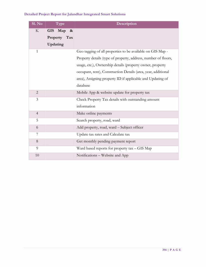
Detailed Project Report for Jalandhar Integrated Smart Solutions
394 | P A G E
Sl. No Type Description
K GIS Map &
Property Tax
Updating
1 Geo tagging of all properties to be available on GIS Map -
Property details (type of property, address, number of floors,
usage, etc.), Ownership details (property owner, property
occupant, rent), Construction Details (area, year, additional
area), Assigning property ID if applicable and Updating of
database
2 Mobile App & website update for property tax
3 Check Property Tax details with outstanding amount
information
4 Make online payments
5 Search property, road, ward
6 Add property, road, ward – Subject officer
7 Update tax rates and Calculate tax
8 Get monthly pending payment report
9 Ward based reports for property tax – GIS Map
10 Notifications – Website and App