designofrotary-mill liners,andtheir backingmaterials - … · thedesignofrotary-millliners,andtheir...
TRANSCRIPT

J. S. A fr. Inst. Min. Metal/., vo!. 91, no. 2.Feb. 1991. pp. 63-75.
The design of rotary-mill liners, and theirbacking materials
by M.S. POWELL *
SYNOPSISAn evaluation was made of the wear and performance characteristics of litter bars, and the cost-life effectiveness
of backing materials for rotary-mill liners.In a large run-of-mine mill in which the litter bars were mounted on grid liners of austenitic manganese steel
(AMS), the liners had an average life that was five to six times that of equivalent unprotected liners. For a singlemill, this is equivalent to annual savings in the cost of materials of up to R320 000, and to a downtime of 100 hours.
Of the five materials tested in a large pebble mill grinding quartzitic ore, AMS grids and 'white iron' blocks per-formed best on a cost-life basis, with possibly improved performance from a real white cast iron. (The 'white iron'was shown by microstructural analysis to contain flake graphite and pearlite, being in reality a grey cast iron.) Thehigh-chromium white iron had by far the longest predicted life, with mild steel a surprising second. Rubber wasshown to last well in this type of mill.
The wear rates of liners change during their lifetimes. The protective effect of litter bars was clearly illustratedby the reduction of over 40 per cent in the wear rates of the liners when the lifter bars were renewed to a heightof 80 mm from a fully worn height of 35 mm.
SAMEVATTINGDie slytasie- en werkverrigtingeienskappe van ligstawe en die koste-Iewensduurdoeltreffendheid van steunmateriale
vir draaimeulvoerings is geevalueer.In 'n groot maul vir onbehandelde arts waarin die ligstawe op roostervoerings van oustenitiese mangaanstaal
(OMS) gemonteer is, het die voerings 'n gemiddelde lewensduur gehad wat vyf tot sas maal langer as die vanekwivalente onbeskermde voerings was. Vir 'n enkele maul is dit gelyk aan 'n jaarlikse besparing van tot R320 000in die materiaalkoste, en van 'n staantyd van 100 uur.
Van die vyf materiale wat getoets is in 'n groot rolklikmeul wat kwartsitiese arts maal, het die OMS-roosters en'witysterblokke' op 'n koste-Iewensduurbasis die baste gewerk, met 'n moontlik beter werkverrigting deur egtewitgietyster. 'n Mikrostruktuurontleding het getoon dat die 'wityster' vlakgrafiet en perliet bevat en in werklikheid'n grysgietyster is.) Die chroomegte wityster het verreweg die langste voorspelde lewensduur gehad met sagtestaalverbasend genoeg tweede. Daar is getoon dat rubber goad in hierdie soort maul hou.
Die slytasietempo van voerings verander gedurende hulleeftyd. Die beskermende uitwerking van ligstawe blykduidelik uit die verlaging van meer as 40 persent in dieSlytasietempo van die voerings nadat die ligstawe tot 'nhoogte van 80 mm hernuwe is vanaf 'n heeltemal verslete hoogte van 35 mm.
IntroductionThis paper evaluates the wear and performance charac-
teristics of lifter bars in relation to their height, togetherwith the cost-life performance of the backing materialsused for liners in rotary mills.
South African gold mines use 688 rotary mills to grindabout 110 Mt of ore annually. The gold occurs principallyin very hard, abrasive quartzitic ore. This fact, togetherwith the high mill speeds that are employed, causes thelinings within the shells of the mills to wear rapidly. Thegross overall average wear of liners in all the mills on thegold mines is 85 kg per day per mill!, and results in atotal annual usage of 20 kt of metal at a cost of aboutR40 million. The total energy! used in milling is 2400million kilowatt-hours at a cost of about R140 million.
It was felt that the use of more suitable materials formill liners and improved design could considerably reducethese costs and the high downtimes required for the fre-quent replacement of worn liners.
Although several studies have been made of the in-stallation of lifter bars in rotary mills, the wear rates oflifter bars and backing blocks, and the effect of lifter bars
. Mintek, Private Bag X3015, Randburg, 2125 Transvaal.@ The South African Institute of Mining and Metallurgy, 1991. SA
ISSN 0038-223X/3.00 +-0.00. Paper r~ceived 9th March, 1990.Modified paper received 10th October, 1990.
on the overall performance of the mill, have not beenfully investigated. In one study, for example, lifter barswere successfully installed in a large, high-speed run-of-mine (ROM) mill but, because this was done in conjunc-tion with a change in backing-block materials, it was notclear as to which change had given rise to the improvedliner life. It has been found that the ratios of lifter-barheight to mill diameter, and lifter-bar height to lifterspacing, have an important influence on the wear rateof liners and the performance of mills. However, the mostsuitable ratios have not been established for the differenttypes of local mills.
It can be seen from the above summary that there aregaps in our understanding of the effect of lifter bars onthe performance of mills and the wear rate of liners. Asthe use of the correct liner .configuration and materials2can considerably reduce downtime and liner wear, andimprove mill operation, it is important that the optimalconditions for these two factors should be established.
ROM mills are used for over a quarter of all the mill-ing done on South African gold mines, and all new minesare installing these mills. It is therefore important thatthe liner lives as experienced in these mills at presentshould be improved. Investigations have indicated thatconsiderable improvements are possible3, which means
JOURNAL OF THE SOUTH AFRICAN INSTITUTE OF MINING AND METALLURGY FEBRUARY 1991 63
that the optimal lifter-bar configuration and backing-block material should be firmly established for thesemills.
The function of milling is to reduce ore to the optimumsize for efficient processing in downstream extractionoperations, and hence any change in liner configurationmust maintain or improve a mill's performance. Thetheory underlying the influence of liner design on themotion of a mill..load has been extensively studied andis published elsewhere4. The conclusions from that workand the results of other investigatorsS were taken intoconsideration when the present experimental work wasdesigned.
The specific aims of the present work were as follows:(a) to assess the effect of lifter bars on the life of the liner
in a ROM mill and the performance of the mill, and(b) to test the suitability of currently available materials
for backing blocks by the measurement of their rela-tive wear rates when used in conjunction with lifterbars of a suitable configuration.
The tests on (a) were conducted in the number 1 ROMmill at Deelkraal gold mine, which had been newly fittedwith lifter bars mounted on flat grids. Those on (b) in-volved the installation of five different materials in asingle pebble mill at Kloof gold mine.
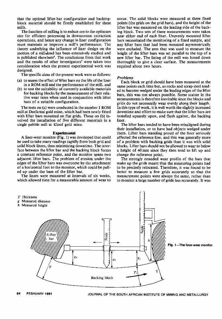
ExperimentalA liner-wear monitor (Fig. 1) was developed that could
be used to take many readings rapidly from both grid andsolid block liners, thus minimizing downtime. The inter-face between the lifter bar and the backing block formsa constant reference pQint, and the monitor spans twoadjacent lifter bars. The problem of erosion under theedges of the lifter bars was overcome by the attachmentof a horizontal foot to the monitor, which could be pull-ed up under the base of the lifter bar.
The liners were measured at intervals of six weeks,which allowed time for a measurable amount of wear to
T Thicknessg Measured distanceh Measured height
-g3
Backing block
64 FEBRUARY 1991 JOURNAL OF THE SOUTH AFRICAN INSTITUTE OF MINING AND METALLURGY
occur. The solid blocks were measured at three fixedpoints (the grids on the grid bars), and the height of thelifter bar was measured on the leading side of the back-ing block. Two sets of these measurements were takennear either end of each liner. Unevenly mounted lifterbars necessitated the monitoring of a fixed sample, andany lifter bars that had been mounted asymmetricallywere excluded. The arm that was used to measure theheight of the lifter bars was set parallel to the top of anew lifter bar. The lining of the mill was hosed downthoroughly to give a clear surface. The measurementsrequired about two hours.
ProblemsEach block or grid should have been measured at the
same points each time but, as rocks and scrap steel tend-ed to become wedged under the leading edges of the lifterbars, this was not always possible. Some scatter in themeasurements is therefore inevitable since the blocks andgrids do not necessarily wear evenly along their length.In this type of work, it is well worth the slightly increaseddowntime and effort to make sure that the lifter bars areinstalled squarely upon, and flush against, the backingliner.
The lifter bars tended to have been misaligned duringtheir installation, or to have had objects wedged underthem. Lifter bars standing proud of the liner seriouslyaffected the reference line, and this was generally moreof a problem with backing grids than it was with solidblocks. Lifter bars should not be allowed to wear to belowa height of 40 mm since they then tend to lift up andchange the reference point.
The strongly rounded wear profile of the bars thatmake up the grids meant that the measuring points hadto be precisely relocated. Therefore, it was found to bebetter to measure a few grids accurately so that themeasurement points were always the same, rather thanto monitor a large number of grids less accurately. It was
<Ut;u[/J
<Ut;u[/J
-
g2
Tl

1300 Dec. "'Jan. 0 Feb. L!.Apr.
120
110
lOOSS
90,;;
'"Q)
c::80Fig. 3-Progressive average grid thicknesses
,.I<:u
:.a....
70
60
50
40
Ring 1 Ring 2 Ring 3 Ring 4 Ring 5 Ring 6 Ring 7 Ring 8
Mill length
loomm DFig. 2-Profiles of the three types of linings
loommJi-
125 mm
100mb125mm
shown to be preferable to measure the lowest point ona grid bar, which is easier to locate and gives a betterreflection of the maximum wear rate of the grid.
Tests at DeelkraalThis investigation concerned the way in which lifter
bars mounted on top of a grid liner would affect the wearrate of the lining in a large ROM mill. The 4,8 by 12,2 mmill ran at 81 per cent of the critical speed, and was linedwith 24 rows of austenitic manganese steel (AMS) grids.The mill was charged with 5 to 10 per cent 100 mm balls,and was run at 45 per cent charge filling. It was advan-tageous to use a mill of slower speed since this is suitedto perpendicular lifter bars.
The mill had originally been lined with a flat-profiledgrid with an average life of 85 days. It was then fittedwith V-grids, with a lifter bar mounted in the groove andprotruding just above the grid. The life of these gridsaveraged 134 days, with one change of lifter bars. Forthe experimental work, a flat 125 mm thick grid was used,with a 100 mm lifter bar mounted on top of it (Fig. 2).
Course of the InvestigationThe measurements began in May 1987 but, because of
a shortage of speciallifter bars, the need to run the millat double capacity for a month (by increasing the ballcharge to about 20 per cent), and extensive repairs thatthe mill had to undergo, the monitoring of the liners could
I
Original liner, life '85 days
~I
V-grid liner, life 134 days
0I
Experimental liner
start only in December 1987. Six sets of measurementswere taken up to June 1988. Six rows running the fulllength of the mill were monitored, 384 readings beingtaken at a time.
Problems were experienced with the breakage of lifterbars because of poor castings. It is therefore importantto ensure that good-quality lifter bars are used in a millof this size.
ResultsThe progressive grid thicknesses are given in Fig. 3.
These are the measurements taken at the centre of thegrid, which is the fastest-wearing region. The values usedare averages of all six grids measured in a single ring, anymissing measurements being a consequence of brokenlifter bars. It is clear that ring 5 was thinner than the otherrings, which is not a reflection of the wear rate but ratheran indication of the installation date since the rings wereinstalled over a period of months. The inlet edge of ring3 wore to a thinner profile because the old linings in ring2 were much lower than ring 3 for a long period.
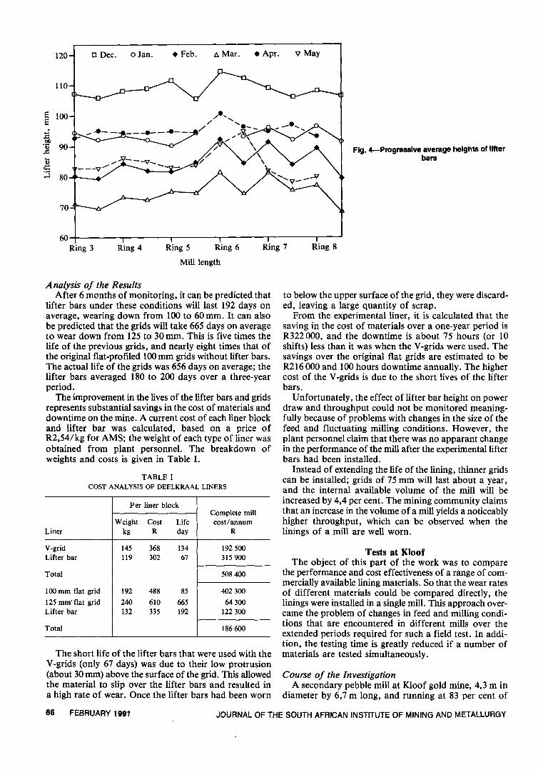
The progressive heights of the lifter bars are shown inFig. 4. The dotted lines link the data for the second setof lifter bars that were installed in April. Because of theproblem with broken lifter bars, insufficient data wereavailable for rings 1 and 2. From ring' 3 onwards, thereis not a significant difference in the wear rates of the dif-ferent rings of lifter bars except for the end of ring 8.
JOURNAL OF THE SOUTH AFRICAN INSTITUTE OF MINING AND METALLURGY FEBRUARY 1991 65
120 0 Dec. clan. . Feb. t:.Mar. . Apr. v May
110
S 100S
~b/).0 90..c:...Q)
.:::;.:3 80
70
60Ring 3 Ring 4 Ring 5 Ring 6 Ring 7 Ring 8
Mill length
Per liner blockComplete mill
Weight Cost Life cost/annumLiner kg R day R
V-grid 145 368 134 192500Lifter bar 119 302 67 315900
Total 508400
100 mm flat grid 192 488 85 402300
125 mm' flat grid 240 610 665 64300Lifter bar 132 335 192 122 300
Total 186600
Analysis of the ResultsAfter 6 months of monitoring, it can be predicted that
lifter bars under these conditions will last 192 days onaverage, wearing down from lOOto 60 mm. It can alsobe predicted that the grids will take 665 days on averageto wear down from 125 to 30 mm. This is five times thelife of the previous grids, and nearly eight times that ofthe original flat-profiled lOOmm grids without lifter bars.The actual life of the grids was 656 days on average; thelifter bars averaged 180 to 200 days over a three-yearperiod.
The improvement in the lives of the lifter bars and gridsrepresents substantial savings in the cost of materials anddowntime on the mine. A current cost of each liner blockand lifter bar was calculated, based on a price ofR2,54/kg for AMS; the weight of each type of liner wasobtained from plant personnel. The breakdown ofweights and costs is given in Table I.
TABLEICOST ANALYSIS OF DEELKRAAL LINERS
The short life of the lifter bars that were used with theV-grids (only 67 days) was due to their low protrusion(about 30 mm) above the surface of the grid. This allowedthe material to slip over the lifter bars and resulted ina high rate of wear. Once the lifter bars had been worn
66 FEBRUARY 1991 JOURNAL OF THE SOUTH AFRICAN INSTITUTE OF MINING AND METALLURGY
Fig. 4-Progressive average heights of litterbars
to below the upper surface of the grid, they were discard-ed, leaving a large quantity of scrap.
From the experimental liner, it is calculated that thesaving in the cost of materials over a one-year period isR322 ooO, and the downtime is about 75 hours (or 10shifts) less than it was when the V-grids were used. Thesavings over the original flat grids are estimated to beR2l6000 and 100 hours downtime annually. The highercost of the V-grids is due to the short lives of the lifterbars.
Unfortunately, the effect of lifter bar height on powerdraw and throughput could not be monitored meaning-fully because of problems with changes in the size of thefeed and fluctuating milling conditions. However, theplant personnel claim that there was no apparant changein the performance of the mill after the experimentallifterbars had been installed.
Instead of extending the life of the lining, thinner gridscan be installed; grids of 75 mm will last about a year,and the internal available volume of the mill will beincreased by 4,4 per cent. The mining community claimsthat an increase in the volume of a mill yields a noticeablyhigher throughput, which can be observed when thelinings of a mill are well worn.
Tests at KloofThe object of this part of the work was to compare
the performance and cost effectiveness of a range of com-mercially available lining materials. So that the wear ratesof different materials could be compared directly, thelinings were installed in a single mill. This approach over-came the problem of changes in feed and milling condi-tions that are encountered in different mills over theextended periods required for such a field test. In addi-tion, the testing time is greatly reduced if a number ofmaterials are tested simultaneously.
Course of the InvestigationA secondary pebble mill at Kloof gold mine, 4,3 m in
diameter by 6,7 m long, and running at 83 per cent of

I
A
2
B
3
v; COJ)
I':~4
D
5
E
6
F
the critical speed, was fitted with five different linermaterials that were protected by lifter bars (Fig. 5).Because the wear of the liners is uneven down the lengthof a mill, all five materials were installed in the same ring.In addition, a buffer ring was fitted on either side of thetest ring to prevent the wear of the adjacent liners fromaffecting the results. All the liners had the same flat pro-file, were 80 mm thick, and were mounted under iden-tical AMS lifter bars that were 80 mm high. These lifterbars isolated adjacent rows of materials from oneanother, and ensured that each material was subjectedto identical conditions of wear.
As white cast iron is too brittle to be bolted down, ithad to be wedged in place by AMS key bars. Because ofthe widely different weights of the various types of back-ing blocks, three of the materials were each divided intotwo groups and placed on opposite sides of the mill. Thenormal stagger along the edge of each ring (designed toprevent wash between the rings) had to be straightenedout along the edge of the 'white iron'. blocks to allowfor the fact that they were wedged between lifter bars.Oversize lining blocks had to be placed in the rows oneither side of the set of 'white iron' to compensate forthe half-block mismatch. Because of these problems, the'white iron' was placed in a single group, with the high-chromium white iron (HCWI) on the opposite side of the.Actually grey iron shown by microstructural analysis to contain flake
graphite and pearlite.
mill.The AMS was cast as a grid. since this is its standard
form when used in this type of mill, and the rest werecast as solid blocks. The materials were bolted centrallyunder the lifter bars, except for the 'white iron'. A rub-ber lining is usually clamped down between speciallifterbars. To enable it to fit in with the experimental arrange-ment, three lugs were welded onto a 5 mm thick mild-steel plate for the lifter bar to be mounted on, and therubber was cast onto this backing (Fig. 6). This configura-tion is far from ideal for rubber, but it was felt that thetest would still serve to indicate whether rubber liningscan last in large, high-speed mills grinding quartzitic ores.Mild steel is not normally used as a mill lining, but wasinstalled to demonstrate the way in which a relatively softlow-carbon steel would perform when protected by lifterbars.
All the liners were numbered on the back with an anglegrinder, and then individually weighed on a suspendedelectronic scale accurate to 1 kg. The position of each linerwas noted as it was installed in the mill. The installationof the experimental liners took 2 days, compared withthe normal 8 hours of downtime that are required toreplace two rings. The relining gang experienced some dif-ficulty in handling the solid blocks, which each weighedabout 250 kg. The oversize grids and mild-steel blocksthat were required to fit in on either side of the 'whiteiron' were well-designed and fitted easily, but were
Feed end
--------------r\7/"'-P::
t-- - -f--
'\""fl\O~\/~' '.0'.'."'"""""""",:::::/ ,11'" \-"""'" ","""".'~~ ~/\ ~~ :~ I'~ // ::/ :::::x.~y~;\~ ;.};/~ 1~: ~'~ ~~ 0,' t\~~;';: \~~: > ::> :::: :~~~~~i{~i. ~~:~~:\,\'f)I,\\
'«'.'0"""'" """""":0\: '",\"""/""', .','."'"::;."".'1 ,,\'ii:.:::::::::::::::::::':~~:~::'::,::::;,::,:,:::::~~:::""'~-I_\\I'\-'-"2::::::::::::::: ::':;~~~'~
14 16 18Discharge endRow number
[] d Mild steel
D e Rubber
2 4 8 106 12
D a Austenitic manganese steel
~ b White iron
u c High-chromium white iron
20 22 2824 26 30 32
Fig. 5- The lining of the Kloof experimental milla AMSto SABS 407, type 2, containing 11,5 to 14,5 percent c 'Whlteiron' containing 2,4 to 3,4 percent carbon and 0,5
manganese and 1,0 to 1,3 per cent carbon to 1,5 per cent siliconb HCWIto BS 4844 pt 3, grade 3D, containing 27 per cent d Mild steel (carbon steel, grade A2)
chromium e Rubber to Skega specifications
JOURNAL OF THE SOUTH AFRICAN INSTITUTE OF MINING AND METALLURGY FEBRUARY 1991 67

~~G ~ LUg---~~-Pto fit in bolt hole
Lifter bar
c::::J CJ c=J CJ CJ c=JDcm~c?@~[7@~~~~~~c=J c:J c::=Jc=J c=J 11
Austenitic manganese steel grid
~,
,
~, ~I,,
Steel lug tosupport lifter bar \
~eCJRubber
'White iron'
Fig. 6-Conligurations 01 the test linings
cumbersome to handle. The experimental lining andmeasurements are illustrated in Figs. 7 and 8.
After six months, the lifter bars were changed, fourof the materials were removed after 13 months in service,and the HCWI was removed after 2Yz years. After athorough scraping down and washing to remove theremaining dirt, the old liners were weighed so that theirweight loss could be determined (Fig. 9). Because the'white iron' blocks were securely packed in with slurry,their impact toughness was put to the test in the removalprocess (Fig. 10). None of them appeared to be any theworse for the pounding they had received from the sledge-hammer.
ResultsAll the materials performed well for the first 13
months, and those materials which were not expected tolast through to the next changing of lifter bars wereremoved. The AMS grids were fully worn through to thebacking plates; the rubber was holed through in someplaces and heavily impregnated with thin strips of wireand scrap steel (Fig. 11). The 'white iron' blocks wereworn down to nearly 24 mm at the centre but showed nosign of cracking. This meant that they could probablyhave been worn down to less than 20 mm. The mild steelhad plenty of life left in it and could have lasted to thenext change of lifter bars.
The wear modes of the various materials is discussedbriefly in the Addendum. The progressive average wearprofile of the 'white iron' is shown in Fig. 12. The lifterbar is shown on the left, and each set of bars is repre-sented by separate vertical lines. A systematic wear pat-tern can be observed, but it should be noted that the timeintervals between readings were not regular. The averagethicknesses of all the materials on the centre line betweenthe lifter bars except for the grids, which were measuredoff centre, were reduced fairly steadily (Fig. 13). It is im-portant to observe that, because all these thicknesses weremeasured from the shell, they include the backing platesof the grids and of the rubber.
68 FEBRUARY 1991 JOURNAL OF THE SOUTH AFRICAN INSTITUTE OF MINING AND METALLURGY
Fig. 7-An interior view 01 theKlool mill, showing the dischargegrate in the background. Thematerials are, Irom left to right,AMS grids, rubber, mild steel,and 'white iron'. The over-size
mild-steel block is arrowed

Fig. 8- Taking measurements ofthe HCWI blocks
Fig. 9- The worn blocks being weighed
The surface and bulk hardnesses of the materials weremeasured in an effort to assess the degree of work harden-ing that they had undergone while they were in the mill(Table 11). The 'white iron' had a scatter in hardnessesbecause of its uneven composition and porosity, and nosignificant difference could be found between its surfaceand its bulk hardness, as was expected; the unexpectedlylow hardness values indicated that this was not a whitecast iron. A microstructural analysis was therefore car-
Fig. 10-'White iron' blocks during removal
ried out6, which revealed the microstructure of flakegraphite and pear lite that is typical of a grey cast iron.A white cast iron would consist of hard cementite andpear lite. The AMS had work-hardened fairly well, butnot to its full potential of an HVIOof around 500. Thisindicates that it should perform even better, when com-pared with the other materials, under more severe impact-ing conditions. These results demonstrate that impactingin a pebble mill of this size is not as severe as one might
JOURNAL OF THE SOUTH AFRICAN INSTITUTE OF MINING AND METALLURGY FEBRUARY 1991 69

Fig. 11-A fully worn section of therubber liner, showing the massive
amount of steel that pierced it
180
1600 17 Dec. 0 7 Jan. <>23 Feb.
<>23 Sep.
f>.24 Mar. . 5 May
v 23 Jun. 015 Aug. f>.1ONov. .6 Jan.140
e 120e
Fig. 12-The progressive average wearprofiles of the 'white Iron'
~ 100d
~0
~ 80
ee 60,;;
'"<I)d~ 50:E'~
70
60
40
200 100 150 300 350200 25050
Circumference measured between lifters, mm
90
80
0 Mild steel0 High-chromium white ironv 'White iron'f>. Rubber
<> AMS grids70
Fig. 13-Average material thicknessesthroughout the testwork
40
30
200,0 0,2 0,3
Mass, Mt
0,4-0,1 0,5
FEBRUARY 1991 JOURNAL OF THE SOUTH AFRICAN INSTITUTE OF MINING AND METALLURGY

Weight Volume Daily wear Predictedloss loss rate life
Material kg litre ml day
Mild steel 83,1 10,8 27,2 563'White iron' 90,6 12,8 32,1 420Rubber 17,3 14,9 37,6 421AMS grids 38,2 13,6 34,3 384High chromium 124 16,1 17,6 917
Life based on heightloss Life based on
volume lossMaterial Mt day day
Mild steel 0,72 561 563'White iron' 0,54 422 420Rubber 0,59 458 421AMS grids 0,51 396 384High chromium 1,20 935 917
TABLE 11HARDNESS MEASUREMENTS
Hardness, HVw
Material Bulk Surface
Mild steelAustenitic manganese steel'White iron'High chromium
166240225620
232390225 (194 to 252)620
expect.
A nalysis of the ResultsAfter each measurement, the wear rates and predicted
lifetimes of each material were calculated. The weightlosses in the central liner blocks, which give a truerepresentation of the wear rates, were averaged for eachmaterial. These were then converted to volume losses sothat the various materials could be compared (Table Ill).The density of the rubber was found to be 1,16 g/ cm3,'white iron' 7,10 g/cm3 (porous casting), and the otheralloys 7,7 g/cm3. The net average density of the gridswas taken to be their initial weight divided by the totalvolume of an equivalent solid block, which yielded a valueof 2,8 g/cm3.
T ABLE III
COMPARATIVE WEAR RATES OF MATERIALS
When the blocks had worn down to a minimum thick-ness of 10 mm they had a volume loss of about 16 litres,and the 'white iron', when it had worn down to 20 mm,had a loss of about 14 litres. The profiles were measuredwith vernier calipers on a few blocks of each material,and these volume losses were calculated from the esti-mated final profiles of the fully worn blocks. Because thegrids were completely worn, their volume loss was takento be what had been calculated when they were removed.This volume loss was 13,6 litres for a minimum thicknessof 20 mm on the bar closest to the centre. The predictedlives can be calculated from these figures. For the HCWI,the lower wear rate of 0,0617 mm per day after the initial6-month wear-in period was used.
The calculated lifetimes were compared with thelifetimes predicted by measurements of the height loss(Table IV). In general, there is an excellent correlationbetween the lifetimes predicted by height losses and thosepredicted by volume losses. The discrepancy for the rubbercould have arisen from its uneven wear characteristics.The slowest-wearing material had a life of just over twicethat of the fastest-wearing material, which is a typicalresult when dealing with very abrasive quartzitic ores. Thedifference can be expected to increase dramatically in the
TABLE IVCOMPARATIVE LIFETIMES PREDICTED FROM HEIGHT-
AND VOLUME-LOSS
grinding of softer ores.The progressive predicted lifetimes (Fig. 14) tended to
drop over the life of the first set of lifter bars, but thensettled into a steadily increasing regime in which all thematerials yielded progressively longer predicted lives withincreasing wear. This indicates two important points.Firstly, it appears that the lifetime of a lining cannot bepredicted from its initial wear rate since this changes withtime, especially when lifter bars are used. Secondly, it isapparent that the height of lifter bars influences the wearrate of liner blocks.
Fig. 15 illustrates the effect of changes in the heightof lifter bars on wear rates. The wear rates were measuredfrom each change of lifter bars so that the influence ofthe lifter bars is emphasized. The wear rates of all thematerials, with the exception of the grids, increased andthen levelled off until the lifter bars, which were wornto a height of about 35 mm, were changed. A dramaticdrop in the wear rate, averaging more than 40 per cent,was observed in all the materials directly after the lifterbars had been renewed to a height of 80 mm. Thisdemonstrates the substantial protective effect that lifterbars have on the lining.
After the lifter bars had been changed, three of thematerials experienced a general decrease in wear. It isthought that, as the materials become thinner, they areafforded more protection by the lifter bars since they arethen much lower than the top of the bars. The wear rateof the rubber liners continued to increase because theycould not effectively absorb the impacting once they hadworn to below a thickness of 10 mm, at which stage therubber tended to become holed through. The grids werestill well packed with pebbles up to the first change oflifter bars, but they lost the ability to be packed with rocksas the pockets became too shallow. Lacking that addedprotection, they showed an increasing rate of wear.
Cost AnalysisA cost analysis based on height-loss life predictions is
set out in Table V. As the experimental conditions didnot allow for a fair testing of the rubber, it is not includedin the cost comparison. It must be stressed that the costsare based on quotations supplied for a single relining ofthe mill, and could therefore vary if large orders wereplaced. The costs are also based on the experimental con-figurations of the lining blocks that were used. Thecosting for the mild steel is particularly uncertain sincethe costs were based on cast mild steel, which is not theusual fabrication method for the material. If low-carbon
JOURNAL OF THE SOUTH AFRICAN INSTITUTE OF MINING AND METALLURGY FEBRUARY 1991 71

Block costMaterial R clt R/year* Relative
AMS grids 289t 11 53 000 1,0'White iron' 315t 11 53 000 1,0Mild steel 847 23 106 000 2,0High chromium 1136 19 87000 1,6Rubber 1049
0 Mild steel0 High-chromium white ironV 'White iron'£:. Rubber
0 AMS grids
1,0
0,9 0
"000
.....
.....0
~0,8
0 0,7~"0
t 0,6:a0....
~ 0,5
0,4
0,3
0,0 0,1 0,2 0,3
Actual life, Mt of feed
200
180
Fig. 15-The progressive average wearrates measured after each change ot litter
bars
-g 160~.....;: 140~"-~ 120
0~ 100....t1S0
~ 80
(mild) steel or medium-carbon steel is considered to bea promising lining material, it may be possible to findan appropriate fabrication route for wrought material,which would be cheaper.
For materials with a longer life, lifter bars still haveto be changed at the same intervals, but a saving indowntime of some hours is affo,rded each time. The realcost of downtime is dependent upon the conditions in aparticular mine, such as the grade of the ore and whetherthe plant is coping adequately with the tonnages that aredemanded. This cost, therefore, was not calculated.
These results, illustrated in Fig. 16, indicate that,although the AMS grids and 'white iron' have the shortestpredicted lifetimes, they are the cheapest on a cost-lifebasis. The HCWI has an excellent lifetime; however, its
72 FEBRUARY 1991 JOURNAL OF THE SOUTH AFRICAN INSTITUTE OF MINING AND METALLURGY
60
400,0
Fig. 14- The progressive predicted linerlives
0,4 0,5
0 0 Mild steel0 High-chromium white ironv 'White iron'£:. Rubber
0 AMS grids~0
£:.
0
0
0,1 0,2 0,3 0,4 0,5
Mass of feed treated, Mt
TABLE VCOST-LIFE COMPARISON
Cost of relining
* This excludes the cost of lifter bars, which is R59 000 per annum andis calculated on the wear rate of ring 4
t R65 is included to allow for a backing plate that lasts for three changesof grids
t R54 is included to allow for an AMS key bar that lasts for threechanges of blocks

1000
900 ~ Life
a Cost800
700
600Fig. 16-Comparison ofthe life and cost of five
materials
'":>.'""0 500~J
400-
300-
200
100
0AMS grids 'White iron'
high initial cost renders it uncompetitive. Rubber suffersfrom a high material cost when compared with metals,and would therefore need to perform much more satisfac-torily to be competitive on a cost-life basis. This perfor-mance could be tested only with the correct configura-tion for the rubber, which should give it an improved life.
The experimental set-up and procedure worked welland yielded good comparative results. The comparisonsof the height- and volume-loss figures are encouraging,but they highlight the importance of knowing to whatextent liners can be worn down.
The incorrect composition and microstructure of the'white iron' compromises the results for this material. Thecementite component of white cast iron results in itshaving a higher wear resistance than the grey cast ironthat was supplied for this test.
Recommended Future WorkThe most important continuation of this work would
involve tests on the effect of lifter bars on the perfor-mance (throughput and grind) of a mill. Another naturalcontinuation of the work is the testing of further materialsin the Kloof pebble mill, and this work has already begunwith the installation of three new materials in the mill.It is also necessary to repeat the earlier tests on true whitecast iron and to ensure that its composition and micro-structure are correct before it is installed in the mill. Itwould be useful to conduct similar tests in a large ROMmill since the results obtained on the pebble mill are notnecessarily transferable. The conditions are considerablymore severe in ROM mills, particularly because of theimpacting of balls and large rocks. Now that it has beenestablished that rubber can last in a high-speed large-diameter mill grinding quartzite, it would be useful to testrubber in an integral unit mounted under lifter bars ofthe appropriate design.
DiscussionThe work showed that there is a substantial reduction
110
100
90
80 ~!:
70 ~~0
60 2-50 ~
1;;40 830
20
10
0Mild steel High-chromium
white ironRubber
in the wear of linings when lifter bars are installed in aROM mill, since the grids have a lifetime that is five tosix times that of unprotected grids. Lifter bars have morethan double the lifetime of the original flat-profIled grids.This reduction in the rate of wear leads to substantialsavings each year in the cost of materials-up toR266000-and in downtime-75 to 100 hours-for asingle mill. This study avoided the confusion of earlierwork3, in which improvements in the life of liners wereattributed to changes in liner material instead of to theinstallation of lifter bars. The possibility exists thatthinner liners can be used in conjunction with lifter bars,which would provide a greater internal volume to the milland therefore increase its capacity.
Of the five different liner materials protected by lifterbars and installed in a single pebble mill, the AMS gridshad the shortest life (396 days), the high-chromium whiteiron the longest life (917 days), and the mild steel thesecond longest (561 days). On a cost-life basis, the AMSgrids and the 'white iron' blocks were the cheapest, at11 cents per ton, for the full mill lining. The high costof the HCWI made it uncompetitive at 19 cents per tonand, although rubber had a good life, it turned out tobe rather expensive in this application.
This testwork has given only a cost comparison of linermaterials. There are other plant-dependent factors thatshould be considered before a liner is chosen. For in-stance, only the rubber lining prevented the lock-up ofgold concentrate, which is reported to result in a majortie-up of capitaf, and the 'white iron' caused a substan-tiallock-up.
It was noted from the progressive readings taken thatthe initial rate of wear was not the same as the totalaverage wear. This indicates that one cannot predict thelife of a lining from its initial rate of wear, but can obtainonly an initial ranking of various materials.
A dramatic reduction in the wear rates of linings (over40 per cent) achieved by the installation of lifter bars ofan adequate height was apparent when worn 35 mm lifter
FEBRUARY 1991 73JOURNAL OF THE SOUTH AFRICAN INSTITUTE OF MINING AND METALLURGY

bars were replaced with new 80 mm bars.
AcknowledgementsThis work is published by kind permission of Gold
Fields of South Africa Ltd and of Mintek. The assistanceof Mr F.S. Cornelius of Mintek in carrying out a substan-tial portion of the work is acknowledged as having beenessential to this investigation. The co-operation andassistance of the personnel at Kloof and Deelkraal goldmines, and of Mr N.F. Peverett and Mr G.I. G()ssmanof Gold Fields, were invaluable in the course of this work,and are acknowledged with thanks. The sponsorship ofGold Fields and the assistance of Boksburg foundry insupplying some of the materials are also gratefullyacknowledged.
ReferencesI. POWELL, M.S. Survey of milling and mill lining practice on the
South African gold mines. Randburg, Mintek, Report M350. 1987.2. HOWATI, 0.0., and VERMEULEN, L.A. The design of linings for
rotary mills: A major factor in the throughput and consumption ofenergy and meta!. J. S. AIr. Inst. Min. Metal/., vo!. 86. Ju!. 1986.pp. 251-259.
3. POWELL, M.S. The use of lifter bars in rotary mills. Randburg,Mintek, Report M31O. 1987.
4. POWELL, M.S. The effect of liner design on the motion of the outergrinding elements in a rotary mill. To be published in Int. J. Min.Proc.
5. MEADERS, R.C., and MACPHERSON, A.R. Technical design ofautogenous mills. Min. Eng., vo!. 16. 1964. pp. 81-83.
6. WHYTE, P. Randburg, Mintek, private communication, 1989.7. PHILLIPS, AB., and PATTERSON, D.B. The lock-up of gold in run-
of-mine mills at Randfontein Estates. J. S. AIr. Inst. Min. Metal/.,vo!. 88, no. 10. Oct. 1988. pp. 333-343.
AddendumFig. Al compares the modes of wear of mild steel and edge of the mild steel. Extensive deformation and flow
'white iron'. The deep gouging and plastic flow of the of the steel are evident, and numerous gouges and inden-mild steel is in strong contrast to the much shallower tations in the steel highlight the severity of the abrasiveabrasion tracks on the surface of the considerably more wear. On the right of the figure is a polished 110 sectionbrittle 'white iron'. through the surface of the 'white iron', which gives an
The scanning electron microscope (SEM) photograph idea of the profile of the wear tracks. The exposed blockyin Fig. A2 illustrates the random-direction, gouging section that is evident on the centre right edge was almostabrasion of the AMS and the cracking away of the worn wholly removed; the polished section shows the porositysurface layer. of the casting and the surface cracking.
The left photograph in Fig. A3 shows the leading wear
Fig. A1-The wear tracks on the mild steel (left) and 'white iron'
74 FEBRUARY 1991 JOURNAL OF THE SOUTH AFRICAN INSTITUTE OF MINING AND METALLURGY

Fig. A2-Cross-section through the AMS, showing a 450 viewof the wear surface
Fig. A3- The worn surface of the mild steel (left) and an 110 polished section of the 'white cast iron'
JOURNAL OF THE SOUTH AFRICAN INSTITUTE OF MINING AND METALLURGY FEBRUARY 1991 75