design project1
DESCRIPTION
access scaffoldingTRANSCRIPT
Manar Al Omran CoCR. No. 4030177499P.O. Box 46217Jeddah 21532Tel.: (02) 620-4582, 620-0613Fax: (02) 620-7194
Job Title : JUBAIL MOSQUE Dome R.C. Project
Subject: Design of external Access Scaffolding - Dome
Client:Royal Commission J & Y
Contractor:PITCO
Prepared by: S M Ali
Date:01-10-2012
CALCULATION SHEET(STRUCTURAL)
Approved by:M. S. Khan
Date:01-10-2012
INDEX OF CONTENT
S.NO INDEX OF CONTENT1. SCOPE OF WORK2. DESIGN PARAMETERS3. DESIGN CHECK FOR SCAFFOLD PLANK4. DESIGN CHECK FOR TRANSOMS/BEARERS5. DESIGN CHECK FOR RUNNER6. DESIGN CHECK FOR RAKERS7. DESIGN CHECK FOR VERTICAL STANDARD8. LATERAL STABILITY9. CHECK FOR CAPACITY OF BRACE COUPLER10. ATTACHMENT
1

Manar Al Omran CoCR. No. 4030177499P.O. Box 46217Jeddah 21532Tel.: (02) 620-4582, 620-0613Fax: (02) 620-7194
Job Title : JUBAIL MOSQUE Dome R.C. Project
Subject: Design of external Access Scaffolding - Dome
Client:Royal Commission J & Y
Contractor:PITCO
Prepared by: S M Ali
Date:01-10-2012
CALCULATION SHEET(STRUCTURAL)
Approved by:M. S. Khan
Date:01-10-2012
SCOPE OF WORK
ERECTION/ DISMANTLING AND PERIODIC INSPECTION OF THE ERECTED SCAFFOLDING FOR ACCESS OF CONSTRUCTION OF JUBAIL MOSQUE – DOME
LOCATION : JUBAIL SYSTEM OF SCAFFOLDING : MAO CUPLOCK SYSTEM. REFERENCES :
(a) SAUDI ARAMCO SCAFFOLD SAFETY HANDBOOK(SSH)(b) SAES-A-112 METEROLOGICAL AND SEISMIC DATA(c) AISC(ASD),ASCE-7,BS1139,EN74 etc.
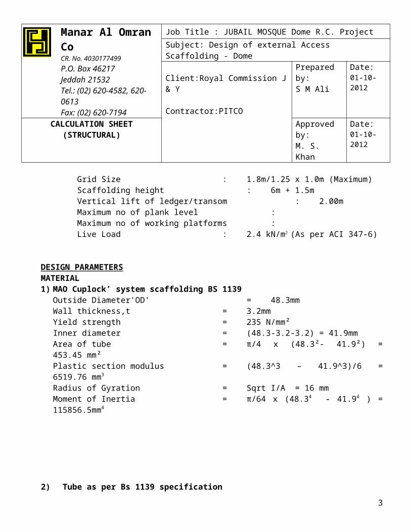
Height of structure : 7.5m(approx from peak point)MAO cuplock system scaffolding : independent run façadeGrid Size : 1.8m/1.25 x 1.0m (Maximum)Scaffolding height : 6m + 1.5mVertical lift of ledger/transom : 2.00mMaximum no of plank level :Maximum no of working platforms :Live Load : 2.4 kN/m (As per ACI 347-6)
DESIGN PARAMETERSMATERIAL1) MAO Cuplock’ system scaffolding BS 1139
Outside Diameter'OD' = 48.3mmWall thickness,t = 3.2mmYield strength = 235 N/mm²Inner diameter = (48.3-3.2-3.2) = 41.9mmArea of tube = π/4 x (48.3²- 41.9²) = 453.45 mm²Plastic section modulus = (48.3^3 – 41.9^3)/6 = 6519.76 mm3
Radius of Gyration = Sqrt I/A = 16 mmMoment of Inertia = π/64 x (48.34 - 41.94 ) = 115856.5mm4
2) Tube as per Bs 1139 specification
2
Manar Al Omran CoCR. No. 4030177499P.O. Box 46217Jeddah 21532Tel.: (02) 620-4582, 620-0613Fax: (02) 620-7194
Job Title : JUBAIL MOSQUE Dome R.C. Project
Subject: Design of external Access Scaffolding - Dome
Client:Royal Commission J & Y
Contractor:PITCO
Prepared by: S M Ali
Date:01-10-2012
CALCULATION SHEET(STRUCTURAL)
Approved by:M. S. Khan
Date:01-10-2012
Outside Diameter'OD' = 48.3mmWall thickness,t = 3.2mmYield strength = 235 N/mm²Weight of tube = 0.035 KN/m
Physical properties of TubeInner diameter = (48.3-3.2-3.2) = 41.9mmArea of tube = π/4 x (48.3²- 41.9²) = 453.45 mm²Plastic section modulus = (48.3^3 – 41.9^3)/6 =6519.76 mm3
Radius of Gyration = Sqrt I/A = 16 mmMoment of Inertia = π/64 x (48.34 - 41.94 ) =115856.5mm4
3) Scaffold Plank (LVL Boards),Hy Plank 42mm x 230mm as per OSHA STANDARD(See attachment)
Weight of scaffold plank = 0.25 KN/m2
Bending stress,Fb = 15.23 MPa.Shear stress,Fv = 0.863 MPa.Youngs Modulus,Eb = 10563 MPa.Area of Cross section,(Ab) = 9660 mm2
Section Modulus = 67620 mm3
Moment of Inertia = 1420020 mm4
Safe Bending capacity = 1.03 KN-mSafe Shear Capacity = 3.34 KN
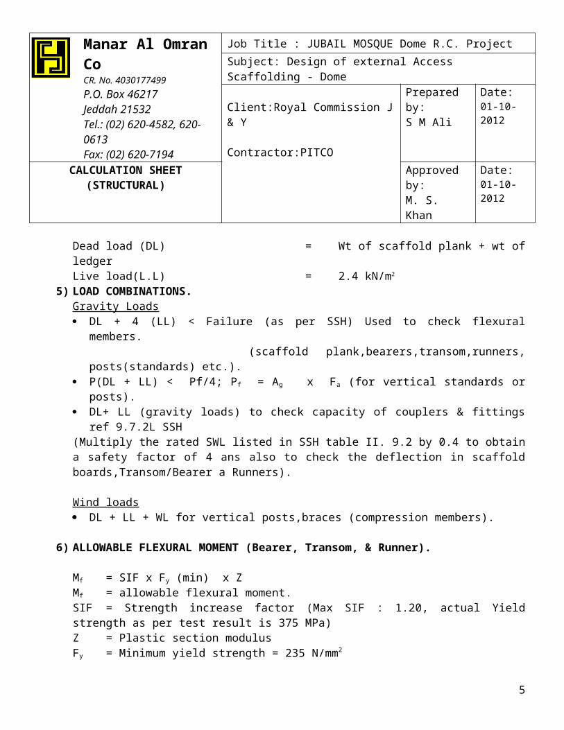
4) LOADINGRating of Scaffolding = Medium Duty RatingDead load (DL) = Wt of scaffold plank + wt of ledgerLive load(L.L) = 2.4 kN/m
5) LOAD COMBINATIONS.Gravity Loads DL + 4 (LL) < Failure (as per SSH) Used to check flexural members.
(scaffold plank,bearers,transom,runners, posts(standards) etc.). P(DL + LL) < Pf/4; Pf = Ag x Fa (for vertical standards or posts). DL+ LL (gravity loads) to check capacity of couplers & fittings ref 9.7.2L SSH(Multiply the rated SWL listed in SSH table II. 9.2 by 0.4 to obtain a safety factor of 4 ans also to check the deflection in scaffold boards,Transom/Bearer a Runners).
Wind loads DL + LL + WL for vertical posts,braces (compression members).
6) ALLOWABLE FLEXURAL MOMENT (Bearer, Transom, & Runner).
3

Manar Al Omran CoCR. No. 4030177499P.O. Box 46217Jeddah 21532Tel.: (02) 620-4582, 620-0613Fax: (02) 620-7194
Job Title : JUBAIL MOSQUE Dome R.C. Project
Subject: Design of external Access Scaffolding - Dome
Client:Royal Commission J & Y
Contractor:PITCO
Prepared by: S M Ali
Date:01-10-2012
CALCULATION SHEET(STRUCTURAL)
Approved by:M. S. Khan
Date:01-10-2012
Mf = SIF x Fy (min) x ZMf = allowable flexural moment.SIF = Strength increase factor (Max SIF : 1.20, actual Yield strength as per test result is 375 MPa)Z = Plastic section modulusFy = Minimum yield strength = 235 N/mm2
Mf = 1.20 x 235 6520 = 1.838 KN-M7) ALLOWABLE SHEAR FORCE CAPACITY (Bearer, Transom, & Runner).
Vc = Allowable shear capacity = 0.4 x Fy x SIF x AFy = Minimum yield strength = 235 N/mm2
A = Area of C/S of tube.
Vc = 0.4 x 235 x 1.2 x (453.45/1000) = 51.15 KN.8) Load carry capacity of MAO ‘Cuplock standard per vertical leg.
P = 59.376 KN (See Item no :19 )
9) Check Scaffold Plank (Boards) Dead Load (DL) = 0.25 KN/m2
Live Load(LL) light duty = 2.40 KN/m2
Loading ‘W’ = DL + 4 LL = 0.25 + 4 x 2.4 =9.85 KN/m2
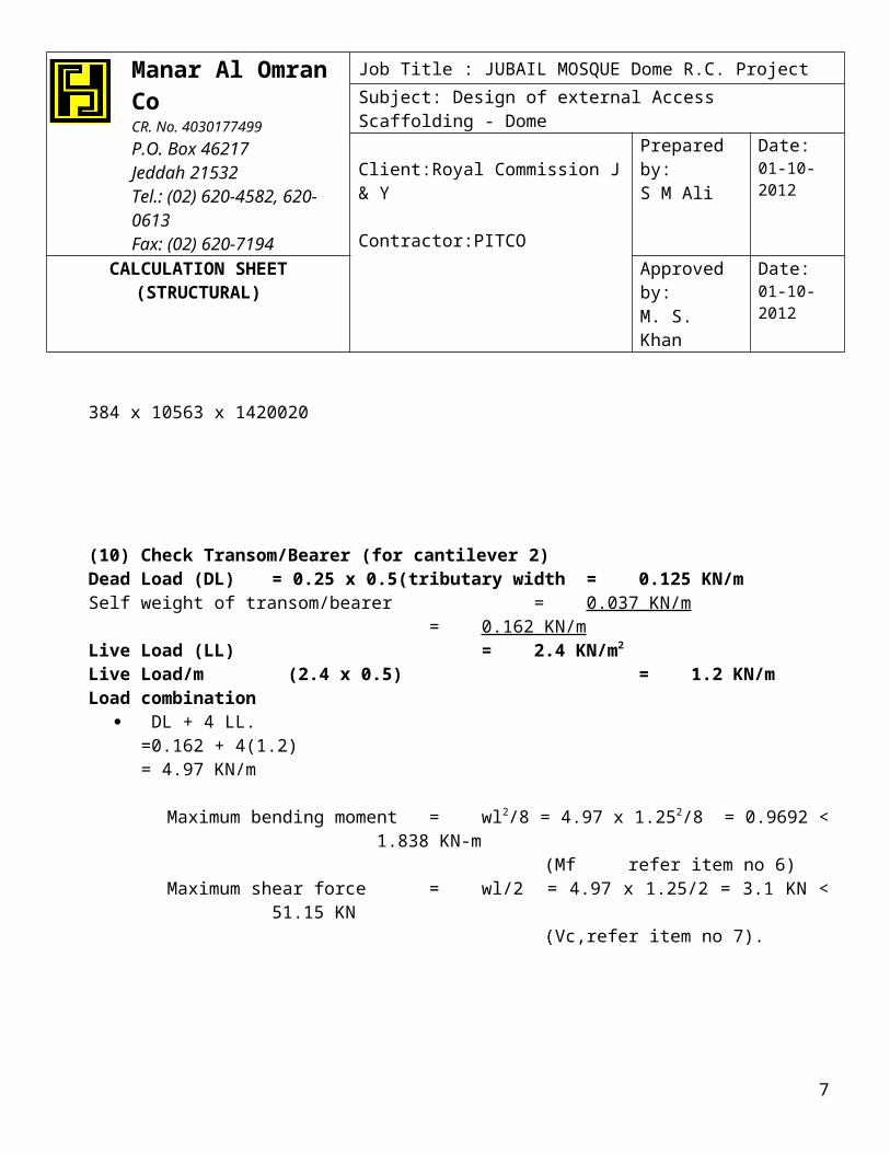
Considering a single plank of 230mm wide strip.Loading /m = 9.85 x 0.23 = 2.2655 KN/m.Spacing of transom/bearer supporting scaffold plank = 1.25m c/c max (from grid size)Maximum bending moment = wl2 /8 = 2.2655 x 1.252 /8 = 0.443 KN-mMaximum shear force = wl/2 = 2.2655 x 1.25/2 = 1.42 KN.Allowable deflection(as per SSH)= L/60 = 1250/60 = 20.833 mmMaximum deflection = 5wl4/384 EI = 5 x 2.2655 x 1250 4 = 4.83mm(safe) 384 x 10563 x 1420020
(10) Check Transom/Bearer (for cantilever 2)Dead Load (DL) = 0.25 x 0.5(tributary width = 0.125 KN/mSelf weight of transom/bearer = 0.037 KN/m
= 0.162 KN/mLive Load (LL) = 2.4 KN/m2
4
Manar Al Omran CoCR. No. 4030177499P.O. Box 46217Jeddah 21532Tel.: (02) 620-4582, 620-0613Fax: (02) 620-7194
Job Title : JUBAIL MOSQUE Dome R.C. Project
Subject: Design of external Access Scaffolding - Dome
Client:Royal Commission J & Y
Contractor:PITCO
Prepared by: S M Ali
Date:01-10-2012
CALCULATION SHEET(STRUCTURAL)
Approved by:M. S. Khan
Date:01-10-2012
Live Load/m (2.4 x 0.5) = 1.2 KN/mLoad combination
DL + 4 LL.=0.162 + 4(1.2)= 4.97 KN/m
Maximum bending moment = wl2/8 = 4.97 x 1.252/8 = 0.9692 < 1.838 KN-m (Mf refer item no 6)
Maximum shear force = wl/2 = 4.97 x 1.25/2 = 3.1 KN < 51.15 KN (Vc,refer item no 7).
(11) Check Runner ledger 1.25m(for cantilever 2)
Maximum bending moment = wl2/8 = 0.37 x 1 2/8 = 0.0049 < 1.838 KN-m (Mf refer item no 6)
Maximum shear force = wl/2 = 0.037 x 1/2 = 0.00195 KN < 51.15 KN (Vc,refer item no 7).
(12) Check Transom/Bearer (for cantilever 1)Dead Load (DL) = 0.25 x 0.375(trib width = 0.09375 KN/mSelf weight of transom/bearer = 0.037 KN/m
= 0.13075 KN/mLive Load (LL) = 2.4 KN/m2
5

Manar Al Omran CoCR. No. 4030177499P.O. Box 46217Jeddah 21532Tel.: (02) 620-4582, 620-0613Fax: (02) 620-7194
Job Title : JUBAIL MOSQUE Dome R.C. Project
Subject: Design of external Access Scaffolding - Dome
Client:Royal Commission J & Y
Contractor:PITCO
Prepared by: S M Ali
Date:01-10-2012
CALCULATION SHEET(STRUCTURAL)
Approved by:M. S. Khan
Date:01-10-2012
Live Load/m (2.4 x 0.375) = 0.9 KN/mLoad combination
DL + 4 LL.=0.13075 + 4(0.9)= 3.74 KN/m
Maximum bending moment = wl2/8 = 3.74 x 1.82/8 = 1.52 KN-m < 1.838 KN-m (Mf refer item no 6)
Maximum shear force = wl/2 = 3.74 x 1.8/2 = 3.37 KN < 51.15 KN (Vc,refer item no 7)
(13) Check Runner ledger 1.0m(for cantilever 1)
Maximum bending moment =wl/8 + Wl = 0.85 < 1.838 KN-m (Mf refer item no 6)
Maximum shear force = wl/2 + W= 3.27KN < 51.15 KN (Vc,refer item no 7).
(14) Check Capacity of Raker Tube(for cantilever 1)
(a) Total load acting on a raker = self wt of tubes,scaffold platform + live loadDead load = 0.25 KN/m2 , Live load = 2.4 KN/m2 Tributary area,A = 0.9m x 1m = 0.9m2
6
Manar Al Omran CoCR. No. 4030177499P.O. Box 46217Jeddah 21532Tel.: (02) 620-4582, 620-0613Fax: (02) 620-7194
Job Title : JUBAIL MOSQUE Dome R.C. Project
Subject: Design of external Access Scaffolding - Dome
Client:Royal Commission J & Y
Contractor:PITCO
Prepared by: S M Ali
Date:01-10-2012
CALCULATION SHEET(STRUCTURAL)
Approved by:M. S. Khan
Date:01-10-2012
Used cantilever platform 1 no at a time
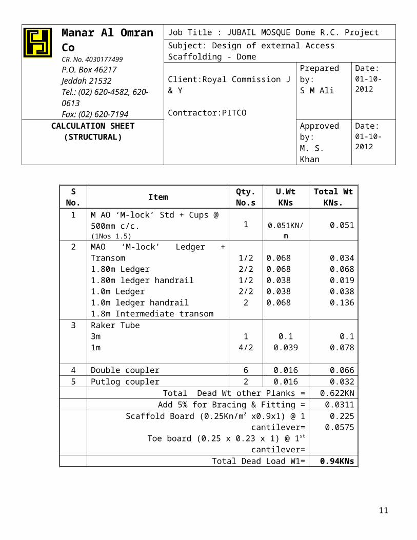
S No. ItemQty. No.s
U.Wt KNsTotal Wt
KNs.1 M AO ‘M-lock’ Std + Cups @ 500mm
c/c.(1Nos 1.5)
1 0.051KN/m 0.051
2 MAO ‘M-lock’ Ledger + Transom1.80m Ledger1.80m ledger handrail1.0m Ledger1.0m ledger handrail1.8m Intermediate transom
1/22/21/22/22
0.0680.0680.0380.0380.068
0.0340.0680.0190.0380.136
3 Raker Tube3m1m
14/2
0.10.039
0.10.078
4 Double coupler 6 0.016 0.0665 Putlog coupler 2 0.016 0.032
Total Dead Wt other Planks = 0.622KNAdd 5% for Bracing & Fitting = 0.0311
Scaffold Board (0.25Kn/m2 x0.9x1) @ 1 cantilever=Toe board (0.25 x 0.23 x 1) @ 1st cantilever=
0.2250.0575
Total Dead Load W1= 0.94KNs
7

Manar Al Omran CoCR. No. 4030177499P.O. Box 46217Jeddah 21532Tel.: (02) 620-4582, 620-0613Fax: (02) 620-7194
Job Title : JUBAIL MOSQUE Dome R.C. Project
Subject: Design of external Access Scaffolding - Dome
Client:Royal Commission J & Y
Contractor:PITCO
Prepared by: S M Ali
Date:01-10-2012
CALCULATION SHEET(STRUCTURAL)
Approved by:M. S. Khan
Date:01-10-2012
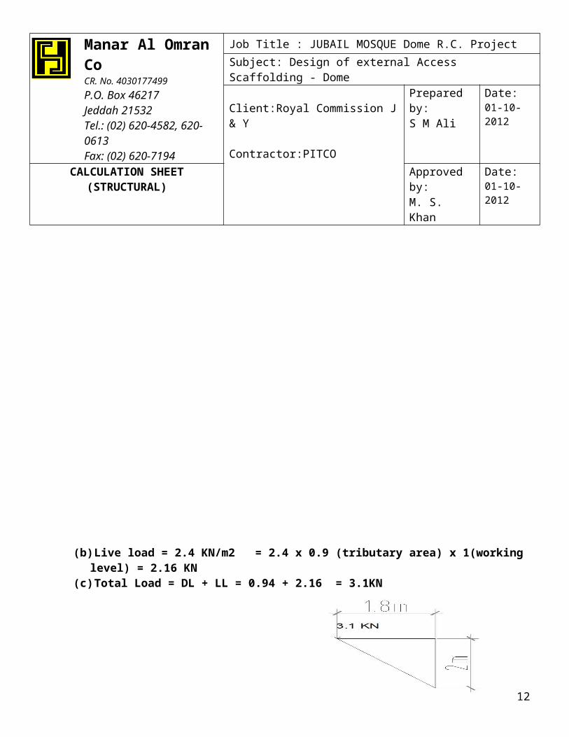
(b) Live load = 2.4 KN/m2 = 2.4 x 0.9 (tributary area) x 1(working level) = 2.16 KN(c) Total Load = DL + LL = 0.94 + 2.16 = 3.1KN
Total load at first raker(cantilever 1) = DL + LL = 3.1 KNAxial Load in Raker = P/sin(48) = 3.1/0.743 = 4.18 KN < 9.627 KN(see attachment )
8
Manar Al Omran CoCR. No. 4030177499P.O. Box 46217Jeddah 21532Tel.: (02) 620-4582, 620-0613Fax: (02) 620-7194
Job Title : JUBAIL MOSQUE Dome R.C. Project
Subject: Design of external Access Scaffolding - Dome
Client:Royal Commission J & Y
Contractor:PITCO
Prepared by: S M Ali
Date:01-10-2012
CALCULATION SHEET(STRUCTURAL)
Approved by:M. S. Khan
Date:01-10-2012
(15) Check the capacity of double couplerSWL in slip of double coupler = 9.4 KNAllowable carrying capacity of coupler = 0.4 x 9.4 = 3.76 KNAxial Load in Raker = p/sin(48) = 4.18/0.743 = 5.62 KN < 2 No’s (0.4 x 9.4 = 3.76 KN)
Used 2 No’s Double coupler at a raker joint connection.
(16) Check Capacity of Raker Tube(for cantilever 2)
9
Manar Al Omran CoCR. No. 4030177499P.O. Box 46217Jeddah 21532Tel.: (02) 620-4582, 620-0613Fax: (02) 620-7194
Job Title : JUBAIL MOSQUE Dome R.C. Project
Subject: Design of external Access Scaffolding - Dome
Client:Royal Commission J & Y
Contractor:PITCO
Prepared by: S M Ali
Date:01-10-2012
CALCULATION SHEET(STRUCTURAL)
Approved by:M. S. Khan
Date:01-10-2012
S No. ItemQty. No.s
U.Wt KNsTotal Wt
KNs.1 M AO ‘M-lock’ Std + Cups @ 500mm
c/c.(2Nos 1.5m, 1 Nos 2m)
1 0.051KN/m 0.255
2 MAO ‘M-lock’ Ledger + Transom1.8m Ledger1.8m ledger handrail1.0m Ledger1.0m ledger handrail1.25m Ledger1.25m ledger handrail
12
2/28/26/24/2
0.0680.0680.0380.0380.0450.045
0.0680.1360.0380.1520.1350.09
3 Raker Tube2.5m1m
14/2
0.0850.039
0.0850.078
4 Double coupler 6 0.016 0.0665 Putlog coupler 4 0.016 0.064
Total Dead weight= 1.167KNAdd 5% for Bracing & Fitting = 0.058
Scaffold Board (0.25Kn/m2 x2.425x1) @ 2nd cantilever=Toe board (0.25 x 0.23 x 1) @ 2nd cantilever=
0.610.0575
Total Dead Load W1= 2.41KNs
10
Manar Al Omran CoCR. No. 4030177499P.O. Box 46217Jeddah 21532Tel.: (02) 620-4582, 620-0613Fax: (02) 620-7194
Job Title : JUBAIL MOSQUE Dome R.C. Project
Subject: Design of external Access Scaffolding - Dome
Client:Royal Commission J & Y
Contractor:PITCO
Prepared by: S M Ali
Date:01-10-2012
CALCULATION SHEET(STRUCTURAL)
Approved by:M. S. Khan
Date:01-10-2012
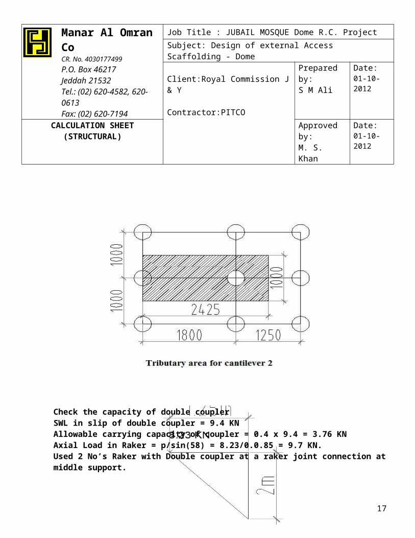
(a) Live load = 2.4 KN/m2 = 2.4 x 2.425 (tributary area) x 1(working level) = 5.82 KN(b) Total Load = DL + LL = 2.41 + 5.82 = 8.23KN
Check the capacity of double couplerSWL in slip of double coupler = 9.4 KNAllowable carrying capacity of coupler = 0.4 x 9.4 = 3.76 KN
11
Manar Al Omran CoCR. No. 4030177499P.O. Box 46217Jeddah 21532Tel.: (02) 620-4582, 620-0613Fax: (02) 620-7194
Job Title : JUBAIL MOSQUE Dome R.C. Project
Subject: Design of external Access Scaffolding - Dome
Client:Royal Commission J & Y
Contractor:PITCO
Prepared by: S M Ali
Date:01-10-2012
CALCULATION SHEET(STRUCTURAL)
Approved by:M. S. Khan
Date:01-10-2012
Axial Load in Raker = p/sin(58) = 8.23/0.0.85 = 9.7 KN.Used 2 No’s Raker with Double coupler at a raker joint connection at middle support.
(17) Check Vertical post(MAO cuplock standard)
S No. ItemQty. No.s
U.Wt KNsTotal Wt
KNs.1 M AO ‘M-lock’ Std + Cups @ 500mm
c/c.(3Nos 2m, 1 Nos 1.5m)
1 0.051KN/m 0.3825
2 Spigot with nuts/bolts attach to standard 4 0.005 0.022 MAO ‘M-lock’ Ledger + Transom
1.0m Ledger1.0m ledger handrail1.25m Ledger1.25m ledger handrail
6/24
6/24
0.0380.0380.0450.045
0.1140.1520.1350.18
3 Bracing Tube2.5m2m
3/21/2
0.0850.071
0.0850.078
4 Double coupler 1 0.016 0.0665 Putlog coupler 4 0.016 0.064
Total Dead weight= 1.28KNAdd 5% for Bracing & Fitting = 0.064
Scaffold Board (0.25Kn/m2 0.625x1) =Toe board (0.25 x 0.23 x 1) =
0.160.0575
Total Dead Load W1= 2.019KNs12

Manar Al Omran CoCR. No. 4030177499P.O. Box 46217Jeddah 21532Tel.: (02) 620-4582, 620-0613Fax: (02) 620-7194
Job Title : JUBAIL MOSQUE Dome R.C. Project
Subject: Design of external Access Scaffolding - Dome
Client:Royal Commission J & Y
Contractor:PITCO
Prepared by: S M Ali
Date:01-10-2012
CALCULATION SHEET(STRUCTURAL)
Approved by:M. S. Khan
Date:01-10-2012
(a) Live load = 2.4 KN/m2 = 2.4 x 0.625 (tributary area) x 1(working level) = 1.5 KNLoad on standard = (DL + LL) + = 2.019 + 1.5 = 3.52KN
Total load on standard = load on standard + load from cantilever 2 = 3.52 + 8.23 = 11.75 KN
P (DL+LL) = Total load on standard = load on standard + load from cantilever 2= 3.52 + 8.23
= 11.75 KN
(18)Check for Buckling of Compression Member (MAO ‘M-Lock’ Vertical)
AssumptionP(DL+LL) = Load due to (Dead Load + Live Load) Per Leg.Pf = Allowable Load due to Allowable Stress (Fa) per Leg.
P(DL+LL) = 3.52 + 8.23 = 11.75 KNs.
Pf = Fa xA = 129.33 x 453.45= 58.645KNs.
Pf /4 = 58.645/4 = 14.66 KNs
** P (DL+LL)< Pf /4 Hence Safe in Buckling of Compression Member.
13

Manar Al Omran CoCR. No. 4030177499P.O. Box 46217Jeddah 21532Tel.: (02) 620-4582, 620-0613Fax: (02) 620-7194
Job Title : JUBAIL MOSQUE Dome R.C. Project
Subject: Design of external Access Scaffolding - Dome
Client:Royal Commission J & Y
Contractor:PITCO
Prepared by: S M Ali
Date:01-10-2012
CALCULATION SHEET(STRUCTURAL)
Approved by:M. S. Khan
Date:01-10-2012
(19) Load Carry Capacity of MAO ‘Cuplock’ Standard per vertical Leg.
Properties of vertical Standard pipes Fy (Min Yeid Strength) = 235 N/mm2
Un braced Length ‘L’ = 2000mm.
Effective Length ‘Leff’=KL = 1.0 x 2000=2000mm
Slenderness Ratio Leff /rmin = 2000/16=125.
Euler critical Stress Cc = Sqrt (2x(π)2xE)/Fy
Sqrt (2x(3.142)2x210000)/235
= 132.83N/mm2.
Leff/rmin < Cc.
Allowable Stress (Corresponding to Leff/rmin = 125)
Fa = {1-( Leff /rmin)2/2 Cc2}x Fy
= {1-(125)2/2 (132.83)2} x 235
= 130.94 N/mm2.
Allowable Load Carry Capacity per vertical ‘Pf’= Fa x A
14

Manar Al Omran CoCR. No. 4030177499P.O. Box 46217Jeddah 21532Tel.: (02) 620-4582, 620-0613Fax: (02) 620-7194
Job Title : JUBAIL MOSQUE Dome R.C. Project
Subject: Design of external Access Scaffolding - Dome
Client:Royal Commission J & Y
Contractor:PITCO
Prepared by: S M Ali
Date:01-10-2012
CALCULATION SHEET(STRUCTURAL)
Approved by:M. S. Khan
Date:01-10-2012
= 130.94 x 453.45=59,376.72N
‘Pf” = 59.376 KNs
20) Lateral Stability of Scaffold
Wind Load Analysis as per ASCE 7-05
Design wind pressure ‘P’
V = Basic Wind Speed (3-second gust) = 93mph = 150km/h=41.67m/s Exposure 'C' for
Jubail as per SAES-A-112
As per ASCE-7 (Table C6-3),the 10-year MRI Wind Speed is 0.84times the 3-second gust.
Hence Wind Velocity V = 41.67m/s x 0.84 = 35.01m/s
Velocity Pressure q z = 0.613 Kz Kzt Kd V2 I
Kz = Velocity Pressure Exposure Coefficient Table 6-3 Exposure C ASCE 7-05
Kzt = Topographic factor = 1.00 as per section 6.5.7 ASCE7-05
Kd = wind directionality Factor = 0.95 table 6.4
I= Importance Factor = 1.0 As per SSH Addendum #2 section 5.0 Wind Load
Wind Pressure P = qz x G x Cf
G = Gust Response factor = 0.85 as per 6.5.8.1
Cf = Force Coefficient
15
Manar Al Omran CoCR. No. 4030177499P.O. Box 46217Jeddah 21532Tel.: (02) 620-4582, 620-0613Fax: (02) 620-7194
Job Title : JUBAIL MOSQUE Dome R.C. Project
Subject: Design of external Access Scaffolding - Dome
Client:Royal Commission J & Y
Contractor:PITCO
Prepared by: S M Ali
Date:01-10-2012
CALCULATION SHEET(STRUCTURAL)
Approved by:M. S. Khan
Date:01-10-2012
Cf = 1.2 for round sections, 2.0 for Rectangular Sections (Toe Boards & Planks) As per
SSH Addendum #2 section 5.0 Wind Load
Ac = Area of Circular section (consider Impact area of wind Load).
Ar = Area of Rectangular section (consider Impact area of wind load).
Pc = Wind Pressure on Circular Sections.
Pr = Wind Pressure on Rectangular Sections.
Wind tributary area increased by 5% to allow for overhangs, overlaps etc
Wind Force ‘F’ = Pc x (Ac x 1.05) + Pr x (Ar x1.05)
Horizontal Surface Area@ every 2.0m consider:
Ac = Area of {(HZ Ledger Runner + Hand Rails) + Vertical Standard + Bracing tube}
= (3x 2 x 0.0483) + 3 x 2 x 0.0483 + 3x 2x 0.0483 + 1 x 2.5 x 0.0483
= 0.90 Sq.m
Ar = Area of Toe board
= 0.23 x 2x2= 0.92 Sq.m
16
Manar Al Omran CoCR. No. 4030177499P.O. Box 46217Jeddah 21532Tel.: (02) 620-4582, 620-0613Fax: (02) 620-7194
Job Title : JUBAIL MOSQUE Dome R.C. Project
Subject: Design of external Access Scaffolding - Dome
Client:Royal Commission J & Y
Contractor:PITCO
Prepared by: S M Ali
Date:01-10-2012
CALCULATION SHEET(STRUCTURAL)
Approved by:M. S. Khan
Date:01-10-2012
Horizontal Lateral Wind Force F1 = 1.87 KN @ every 2.0m level F2 = 1.94 KN @ every 2.0m level F3 = 2.0. KN @ every 2.0m level
Main Brace requirement
Brace Angle = Tan-1 (2/1)= 63.44 deg.
Ht m Kz
Vm/s
q z
KN
/m2
G Cf
(roun
d
section)
Cf
(rectang-
ular section
)
Acx1.05
Arx1.05
Pc
KN
/m2
Pr
KN
/m2
Force
‘F’ K
N
10m 1.000 35.01 0.714 0.85 1.2 2.0 0.945 0.966 0.728 1.214 1.8712m 1.039 35.01 0.741 0.85 1.2 2.0 0.945 0.966 0.756 1.260 1.9415.m 1.073 35.01 0.765 0.85 1.2 2.0 0.945 0.966 0.780 1.30 2
17

Manar Al Omran CoCR. No. 4030177499P.O. Box 46217Jeddah 21532Tel.: (02) 620-4582, 620-0613Fax: (02) 620-7194
Job Title : JUBAIL MOSQUE Dome R.C. Project
Subject: Design of external Access Scaffolding - Dome
Client:Royal Commission J & Y
Contractor:PITCO
Prepared by: S M Ali
Date:01-10-2012
CALCULATION SHEET(STRUCTURAL)
Approved by:M. S. Khan
Date:01-10-2012
V1= Axial Force in Brace / leg = 1.87/Cos (63.44 deg) = 4.18KN< 5.3KN (SWL of Swivel Coupler)
V2= Axial Force in Brace / leg = 1.94/Cos (63.44 deg) = 4.34KN< 5.3KN (SWL of Swivel Coupler)
V3= Axial Force in Brace / leg = 2/Cos (63.44 deg) = 4.473KN< 5.3KN (SWL of Swivel Coupler)
Total Axial Force in Brace transfer to Standards ‘V’ = (4.18+4.34+4.473) = 12.993 KN.
Total Axial Force Transfer in 3 No’s Vertical Standard = 12.993KN/3 = 4.331KN per leg of a Standard.
Therefore Load Combination = DL+LL+WL
DL/ leg = 2.41 KN from Page 7.LL/leg = 5.82 KN from Page 7.WL (Axial Force/ leg)= 4.331KN.
Therefore DL+LL+WL = 2.41 + 5.82 + 4.331 = 12.71KN < Pf (Safe.)
Check Couplers on Vertical Bracing
The Vertical Bracing is connected to the Vertical Standard using Swivel Coupler
SWL of Swivel Coupler in Slip = 5.3 KN.
As per the recommendation of SSH, for wind load in bracing tube, the SWL of couplers shown in table II 9.2 of SSH may be used.SWL in Slip available at the connection = 5.3 KN
**Max Load in brace due to wind load = 4.473 KN < 5.3 KN SWL at Connection Safe.
18