design, optimization and economic feasibility of
TRANSCRIPT
i
A Project Report on
DESIGN, OPTIMIZATION AND ECONOMIC FEASIBILITY
OF ABSORPTION REFRIGERATION SYSTEM USING
(LITHIUM BROMIDE + WATER) AS WORKING PAIR
In partial fulfilment of the requirements for the degree in
Bachelor of Technology in Chemical Engineering
Submitted by
Soumya Ranjan Mohanty
111CH0102
Under the guidance of
Dr. MADHUSHREE KUNDU
Department of Chemical Engineering
National Institute of Technology
Rourkela
2014-15
ii
National Institute of Technology, Rourkela
CERTIFICATE
This is to certify that the thesis entitled, “DESIGN, OPTIMIZATION AND
ECONOMIC FEASIBILITY OF ABSORPTION REFRIGERATION
SYSTEM USING (LITHIUM BROMIDE + WATER) AS WORKING
PAIR”, submitted by Mr. Soumya Ranjan Mohanty, Roll no. 111CH0102, in
partial fulfilment of the requirements for the award of degree of Bachelor of
Technology in Chemical Engineering at National Institute of Technology,
Rourkela is an authentic work carried out by him under my supervision and
guidance.
To the best of my knowledge, the matter embodied in the report has not been
submitted to any other University / Institute for the award of any Degree or
Diploma.
Date: Dr. Madhushree Kundu
Place: Department of Chemical
Engineering
National Institute of Technology
Rourkela – 769008
iii
ACKNOWLEDGEMENT
I express my sincere gratitude to Prof. M.Kundu for providing me an
opportunity to work on this project and for her constant guidance and timely
suggestions throughout. I am also thankful to Prof. P.Chowdhury (Faculty
Advisor) and Prof. P.Rath (Head of The Department) for their valuable
guidance and advice.
Finally I thank all my professors and friends for their support and
encouragement without which this project would not have been possible.
Date: Soumya Ranjan Mohanty
111CH0102
Department of Chemical Engineering
National Institute of Technology, Rourkela
iv
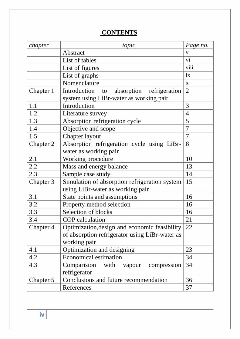
CONTENTS
chapter topic Page no.
Abstract v
List of tables vi
List of figures viii
List of graphs ix
Nomenclature x
Chapter 1 Introduction to absorption refrigeration
system using LiBr-water as working pair
2
1.1 Introduction 3
1.2 Literature survey 4
1.3 Absorption refrigeration cycle 5
1.4 Objective and scope 7
1.5 Chapter layout 7
Chapter 2 Absorption refrigeration cycle using LiBr-
water as working pair
8
2.1 Working procedure 10
2.2 Mass and energy balance 13
2.3 Sample case study 14
Chapter 3 Simulation of absorption refrigeration system
using LiBr-water as working pair
15
3.1 State points and assumptions 16
3.2 Property method selection 16
3.3 Selection of blocks 16
3.4 COP calculation 21
Chapter 4 Optimization,design and economic feasibility
of absorption refrigerator using LiBr-water as
working pair
22
4.1 Optimization and designing 23
4.2 Economical estimation 34
4.3 Comparision with vapour compression
refrigerator
34
Chapter 5 Conclusions and future recommendation 36
References 37
v
ABSTRACT
The global warming and energy crisis have become two most important
environmental problems of this twenty-first century. To overcome these
problems, scientists have worked on inventing different devices to lessen this
impact. Vapour absorption refrigeration cycles are the products of this ideology.
Absorption refrigeration cycle generally works on the solar energy, but it can
also verywell work on waste heat sources i.e. heat generated from data centres,
different industries and from large hotels. If this waste heat is being used then
not only energy crisis will decrease but also environment pollution will reduce
to a greater extent. Though industrial point of view, absorption refrigeration
cycle is an old concept, but from academic point, there is still needed a lot of
works to be carried out to visualise different aspects like its performance, heat
and mass coefficients and fluxes. This project work is based on the simulation,
optimum designing as well as finding out the economic feasibility. LiBr+water
is taken as the working pair to do the simulation, analysis and design of an
absorption refrigeration cycle. At the end of this project work, economic
feasibility has also been found out. When compared with a vapour compression
refrigeration cycle, it can be visualized that the vapour absorption refrigeration
system has an annual profit of around Rs. 7500/- which shows the economical
viability of this refrigeration system.
vi
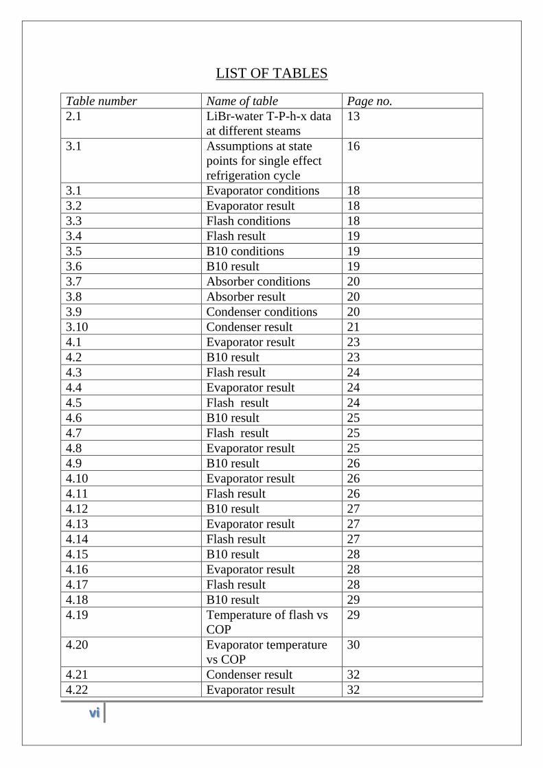
LIST OF TABLES
Table number Name of table Page no.
2.1 LiBr-water T-P-h-x data
at different steams
13
3.1 Assumptions at state
points for single effect
refrigeration cycle
16
3.1 Evaporator conditions 18
3.2 Evaporator result 18
3.3 Flash conditions 18
3.4 Flash result 19
3.5 B10 conditions 19
3.6 B10 result 19
3.7 Absorber conditions 20
3.8 Absorber result 20
3.9 Condenser conditions 20
3.10 Condenser result 21
4.1 Evaporator result 23
4.2 B10 result 23
4.3 Flash result 24
4.4 Evaporator result 24
4.5 Flash result 24
4.6 B10 result 25
4.7 Flash result 25
4.8 Evaporator result 25
4.9 B10 result 26
4.10 Evaporator result 26
4.11 Flash result 26
4.12 B10 result 27
4.13 Evaporator result 27
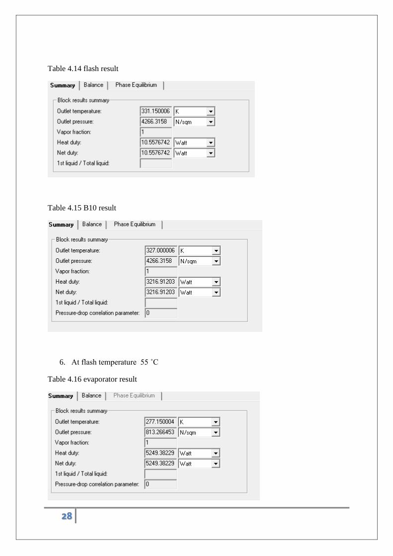
4.14 Flash result 27
4.15 B10 result 28
4.16 Evaporator result 28
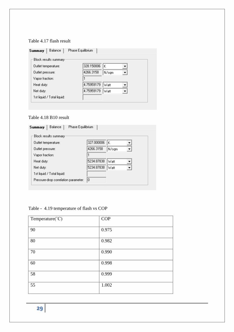
4.17 Flash result 28
4.18 B10 result 29
4.19 Temperature of flash vs
COP
29
4.20 Evaporator temperature
vs COP
30
4.21 Condenser result 32
4.22 Evaporator result 32
vii
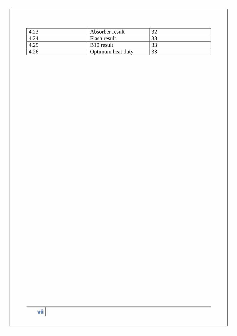
4.23 Absorber result 32
4.24 Flash result 33
4.25 B10 result 33
4.26 Optimum heat duty 33
viii
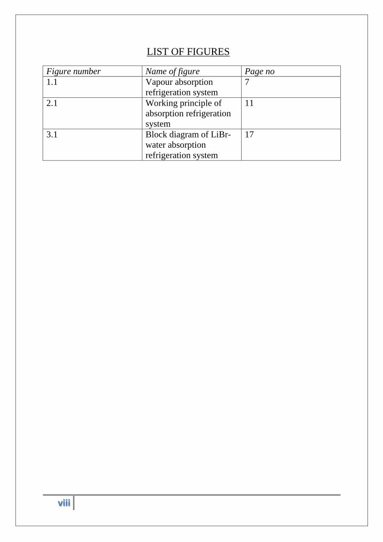
LIST OF FIGURES
Figure number Name of figure Page no
1.1 Vapour absorption
refrigeration system
7
2.1 Working principle of
absorption refrigeration
system
11
3.1 Block diagram of LiBr-
water absorption
refrigeration system
17
ix
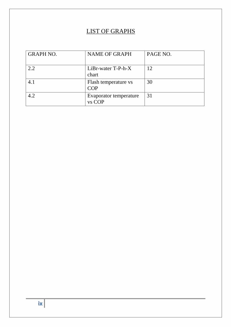
LIST OF GRAPHS
GRAPH NO. NAME OF GRAPH PAGE NO.
2.2 LiBr-water T-P-h-X
chart
12
4.1 Flash temperature vs
COP
30
4.2 Evaporator temperature
vs COP
31
x
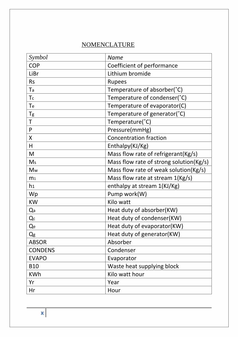
NOMENCLATURE
Symbol Name
COP Coefficient of performance
LiBr Lithium bromide
Rs Rupees
Ta Temperature of absorber(˚C)
Tc Temperature of condenser(˚C)
Te Temperature of evaporator(C)
Tg Temperature of generator(˚C)
T Temperature(˚C)
P Pressure(mmHg)
X Concentration fraction
H Enthalpy(KJ/Kg)
M Mass flow rate of refrigerant(Kg/s)
Ms Mass flow rate of strong solution(Kg/s) Mw Mass flow rate of weak solution(Kg/s)
m1 Mass flow rate at stream 1(Kg/s)
h1 enthalpy at stream 1(KJ/Kg)
Wp Pump work(W)
KW Kilo watt
Qa Heat duty of absorber(KW)
Qc Heat duty of condenser(KW)
Qe Heat duty of evaporator(KW)
Qg Heat duty of generator(KW)
ABSOR Absorber
CONDENS Condenser
EVAPO Evaporator
B10 Waste heat supplying block
KWh Kilo watt hour Yr Year
Hr Hour
1
DESIGN, OPTIMIZATION AND ECONOMIC FEASIBILITY OF
ABSORPTION REFRIGERATION SYSTEM USING (LITHIUM
BROMIDE + WATER) AS WORKING PAIR
2
CHAPTER – 1
INTRODUCTION
3
1.1 INTRODUCTION :-
Today’s world is facing two most important environmental problems. They are the
energy crisis and the green house effect. Scientists are working on how to eradicate these
problems. Most of the today’s innovations are based on this fact. Lithium-Bromide and
water driven absorption refrigeration cycle is a burning example of this concept, which
not only helps in minimizing the fossil fuel usage, hence the reduced CO2 gas emission
but also utilizes the low-grade heat from various industries and data centres.
The vapour absorption refrigeration cycle or the absorption refrigerator is a closed
loop cycle that uses low grade heat (waste heat) to provide cooling or refrigeration . It is
different from the conventionally used vapour compression refrigerator in the sense that it
works on chemical energy rather than electrical energy. The absorption refrigerator uses a
chemical substance as the absorbent which absorbs the refrigerant in the absorber and the
waste heat is being used to recover the refrigerant free absorbent and enable it to be
reused. (Ammonia + water) and (Lithium-bromide + water) are the two commercially
used working pairs for this kind of refrigerators with their operability limitations.
In this project, simulation analysis and design of an absorption refrigeration system
using the LiBr + water working pair has been carried out, where water works as
refrigerant and LiBr works as absorbent. The efficiency of this refrigerator is around 1.0
and from the simulation work, the optimized cycle’s coefficient of performance (COP)
has been found out to be 1.0065. This work also attempts to find out the economic
evaluation of this system in comparison to vapour compression refrigeration cycle. The
project work revels that installing an absorption refrigeration system for low grade heat
recovery is beneficial than the vapour compression refrigeration cycle. This thorough
investigation of this commercially used absorption refrigeration system may pave the
way to carry out similar exercise using some novel working pairs to be used in near
future.
4
1.2 LITERATURE REVIEW :-
In the early twentieth century, vapour absorption refrigerator were used extensively
taking ammonia and water as working pairs, but due to the easy availability of electricity and
developments of vapour compression refrigeration cycle, decreased the use of absorption
refrigerators. The outcome of less efficiency is another factor for its minimal use. But still
now-a-days, these refrigerators may find their usage depending on the availability of low
grade heat, solar and geothermal energy.[1]
A.Yokozeki[1] has first done the modelling of vapour absorption refrigeration using
equation of states. He has considered various refrigerant-absorbent pairs, mainly two
conventionally available pairs i.e LiBr+water and ammonia+water. Though the development
of this kind of absorption refrigeration system have been carried out since 1932, but this kind
of complete thermodynamic study and computer based modelling has made other scientists
and researchers to study the different aspects and behaviours of these kinds of working pairs.
He has done large number of experiments to find out the cycle performance of these kinds of
refrigerators so that the temperature, pressure, concentration and enthalpy data have been
easily found out.
In recent developments of thermal engineering, refrigeration technology plays an
important role in their industrial applications. But as far as the COP is concerned, it has
always posed challenges to the researchers in enhancing the efficiencies of these systems.
The most popular refrigeration and air conditioning system at present is the conventional
vapour compression systems. These systems are popular because of their inexpensiveness and
reliability. However these systems require high grade energy i.e. mechanical or electrical
energy for their operations necessitating depletion of fossil fuel, hence CO2 emission.
Besides, it has been found out that the conventional refrigerants used in these refrigerators are
harmful towards environments and cause ozone layer depletion. Hence the logical alternative
is obviously the vapour absorption refrigerator system which mainly uses low grade heat
energy for the operations and acts as a saviour of thermal pollution. The most interesting
thing of these refrigerators is that, they are environment friendly which is the need of this
hour.[2] S.Kaushik has done the analytical work on absorption refrigeration systems to find
out the COP values [2]. He has done most of his works on LiBr+water system and found out
all the state point enthalpy values experimentally
5
1.3 LIBR + WATER BASED ABSORPTION REFRIGERATION SYSTEM
The use of LiBr + Water for absorption refrigeration system started around 1930s.
The outstanding features of LiBr+water system is the non-volatility of the absorbent i.e. LiBr.
This eliminates the use of rectifier as used in Ammonia+ water based absorption refrigeration
system. Another advantage is the high heat of vaporization of refrigerant i.e. water. But the
use of water as refrigerant also restricts the use in low temperature applications. The COP of
these kinds of refrigeration system is higher than the ammonia + water based refrigeration
system. The thermodynamic analysis of the system involves finding important parameters
like enthalpy, mass flow rates, coefficient of performance (COP), heat and mass transfer and
crystallization in LiBr + Water system[2]. The thermodynamic analysis is carried out with the
following assumptions:-
1. Steady state and steady flow
2. No pressure drops due to friction
3. Pure refrigerant comes out from the generator through the refrigerator circuit in form
of vapour.
Refrigerant absorbent systems should possess some desirable properties for vapour
absorption cycle. These are as follows-
The refrigerant should be more volatile than the absorbent in other words the boiling
point of refrigerant should me less than that of absorbent.
There should be large difference in their boiling points so that it will be easier to separate
them in the generator. This ensures that pure refrigerant flows through the refrigerant
circuit (condenser, expansion valve and evaporator)
The refrigerant should exhibit high solubility with solution in the absorber.
The absorbent should have strong affinity for the refrigerant, this will minimize the
amount of refrigerant to be circulated.
Operation pressure should be low so that the pipe walls need not to be strong.
It should not undergo crystallization otherwise, it will block the pipes and flowrates will
be changed
The mixture should be chemically stable, safe and inexpensive.
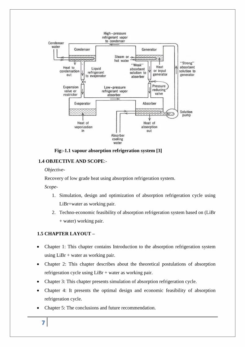
Fig.1.1 presents the working principle of vapour-absorption refrigeration cycle.. As its
name indicates, the vapour absorption refrigerator contains an absorber and a generator
6
instead of a compressor (which is an integral part in vapour compression system). Different
parts of a vapour absorption refrigerator are as follows:-
1. Evaporator
2. Absorber
3. Generator
4. Condenser
Water enters the evaporator at low temperature and pressure. Here water is in vapour –liquid
state. This water refrigerant absorbs heat from the substance to be chilled and gets fully
evaporated. As the boiling point of the refrigerant is high, process is being carried out in a
low pressure or almost vacuum condition. This low pressure or vacuum condition helps in
reducing the boiling point temperature of the refrigerant. A temperature around 3-4 ˚C can
vaporise the water refrigerant. Then this water vapour enters the absorber section at constant
pressure. Concentrated LiBr solution is present in absorber. Since water is highly soluble in
LiBr solution, water vapour is absorbed through this concentrated solution making it dilute.
At this point, it can be stated that, the power consumed by the compressor, is saved by this
chemical absorption process which makes this system more energy saving and eco-friendly.
From this absorber, dilute solution of LiBr+water is carried to the generator through a pump.
Generator is the section where the refrigerant and absorbent are separated. Here heat is
supplied to the solution. This heat is generally the waste heat coming out from data centres,
steam power plants, hotels or big apartments. Water vaporises from the solution and moves to
the condenser and the dilute LiBr+water solution becomes concentrated again and moves to
the absorber. Condenser block is used as a device to condense the water vapour to liquid
water. This can be done by passing normal cooling water or air flow. Generally a valve is
used to reduce the pressure that is required in the evaporator.
7
Fig:-1.1 vapour absorption refrigeration system [3]
1.4 OBJECTIVE AND SCOPE:-
Objective-
Recovery of low grade heat using absorption refrigeration system.
Scope-
1. Simulation, design and optimization of absorption refrigeration cycle using
LiBr+water as working pair.
2. Techno-economic feasibility of absorption refrigeration system based on (LiBr
+ water) working pair.
1.5 CHAPTER LAYOUT –
Chapter 1: This chapter contains Introduction to the absorption refrigeration system
using LiBr + water as working pair.
Chapter 2: This chapter describes about the theoretical postulations of absorption
refrigeration cycle using LiBr + water as working pair.
Chapter 3: This chapter presents simulation of absorption refrigeration cycle.
Chapter 4: It presents the optimal design and economic feasibility of absorption
refrigeration cycle.
Chapter 5: The conclusions and future recommendation.
8
CHAPTER 2
THEORETICAL POSTULATIONS OF ABSORPTION
REFRIGERATION CYCLE USING LiBr+WATER AS WORKING PAIR
9
ABSORPTION REFRIGERATION CYCLE –
Absorption refrigerator is a chemically driven refrigeration system which uses an absorbent-
refrigerant combination as the main working pair. In case of LiBr+water combo, LiBr
solution works as absorbent whereas water works as refrigerant. The basic features that make
it convenient to use this combination as working pair is as follows [2]:-
The refrigerant should be more volatile than the absorbent in other words the boiling
point of refrigerant should me less than that of absorbent. This feature is easily
followed by LiBr+water working pair.
There should be large difference in their boiling points so that it will be easier to
separate them in the generator. This ensures that pure refrigerant flows through the
refrigerant circuit (condenser, expansion valve and evaporator). This property is also
smoothly followed by this pair as LiBr solution has a much higher boiling point than
the refrigerant water.
The LiBr solution has a strong affinity for the refrigerant water.
LiBr+water solution is cheap, environment-friendly and non-toxic.
The above features make this working pair more user friendly and eco-friendly to use in the
absorption refrigeration cycle. But there are some limiting factors that need to have a close
look while using this pair otherwise it will lead to a bigger problem [5]. These are as follows,
As working absorbent is an electrolyte solid in a solution form, higher concentration can lead
to crystal formation which can block the pipes, hence it is needed to have a high pressure in
the condenser and generator so that crystallization won’t happen at the working temperatures.
Anti-crystallizers are being used to overcome this problem.[4]
As the refrigerant used here is water hence it is needed to have a vacuum condition in
the evaporator to decrease the boiling point of water. To maintain this vacuum
condition is also a big challenge.
Corrosion is another big problem. As water carries dissolved oxygen, this system is
prone to metallic corrosion. This can be avoided by using anti-corrosive materials for
the construction of this system.
Significance of vacuum condition can be found out from the boiling point reduction of
refrigerant. Boiling point of water is a function of pressure. At atmospheric pressure,
10
water boils at 100 ˚C. If pressure is lowered, then boiling point also decreases. The
boiling point of water at 6mmHg comes down to 3.9 ˚C. Hence water can be easily
evaporated with addition of less amount of heat.
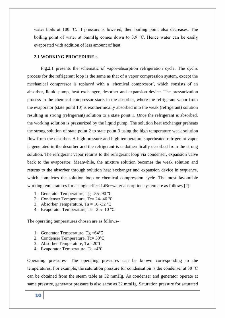
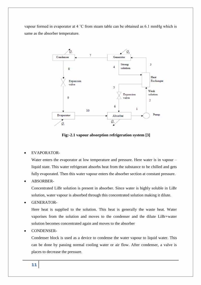
2.1 WORKING PROCEDURE :-
Fig.2.1 presents the schematic of vapor-absorption refrigeration cycle. The cyclic
process for the refrigerant loop is the same as that of a vapor compression system, except the
mechanical compressor is replaced with a ‘chemical compressor’, which consists of an
absorber, liquid pump, heat exchanger, desorber and expansion device. The pressurization
process in the chemical compressor starts in the absorber, where the refrigerant vapor from
the evaporator (state point 10) is exothermically absorbed into the weak (refrigerant) solution
resulting in strong (refrigerant) solution to a state point 1. Once the refrigerant is absorbed,
the working solution is pressurized by the liquid pump. The solution heat exchanger preheats
the strong solution of state point 2 to state point 3 using the high temperature weak solution
flow from the desorber. A high pressure and high temperature superheated refrigerant vapor
is generated in the desorber and the refrigerant is endothermically desorbed from the strong
solution. The refrigerant vapor returns to the refrigerant loop via condenser, expansion valve
back to the evaporator. Meanwhile, the mixture solution becomes the weak solution and
returns to the absorber through solution heat exchanger and expansion device in sequence,
which completes the solution loop or chemical compression cycle. The most favourable
working temperatures for a single effect LiBr+water absorption system are as follows [2]-
1. Generator Temperature, Tg= 55- 90 ℃
2. Condenser Temperature, Tc= 24- 46 ℃
3. Absorber Temperature, Ta = 16 -32 ℃
4. Evaporator Temperature, Te= 2.5- 10 ℃.
The operating temperatures chosen are as follows-
1. Generator Temperature, Tg =64℃
2. Condenser Temperature, Tc= 30℃
3. Absorber Temperature, Ta =20℃
4. Evaporator Temperature, Te =4℃
Operating pressures- The operating pressures can be known corresponding to the
temperatures. For example, the saturation pressure for condensation is the condenser at 30 ˚C
can be obtained from the steam table as 32 mmHg. As condenser and generator operate at
same pressure, generator pressure is also same as 32 mmHg. Saturation pressure for saturated
11
vapour formed in evaporator at 4 ˚C from steam table can be obtained as 6.1 mmHg which is
same as the absorber temperature.
Fig:-2.1 vapour absorption refrigeration system [3]
EVAPORATOR-
Water enters the evaporator at low temperature and pressure. Here water is in vapour –
liquid state. This water refrigerant absorbs heat from the substance to be chilled and gets
fully evaporated. Then this water vapour enters the absorber section at constant pressure.
ABSORBER-
Concentrated LiBr solution is present in absorber. Since water is highly soluble in LiBr
solution, water vapour is absorbed through this concentrated solution making it dilute.
GENERATOR-
Here heat is supplied to the solution. This heat is generally the waste heat. Water
vaporises from the solution and moves to the condenser and the dilute LiBr+water
solution becomes concentrated again and moves to the absorber
CONDENSER-
Condenser block is used as a device to condense the water vapour to liquid water. This
can be done by passing normal cooling water or air flow. After condenser, a valve is
places to decrease the pressure.
12
HEAT-EXCHANGER-
Normally a heat exchanger is used between generator and absorber so that heat can be
exchanged between dilute solution and concentrated solutions.
PUMP-
Pump is used to move the dilute solution from absorber to the heat exchanger so that the
required flow rate can be maintained.
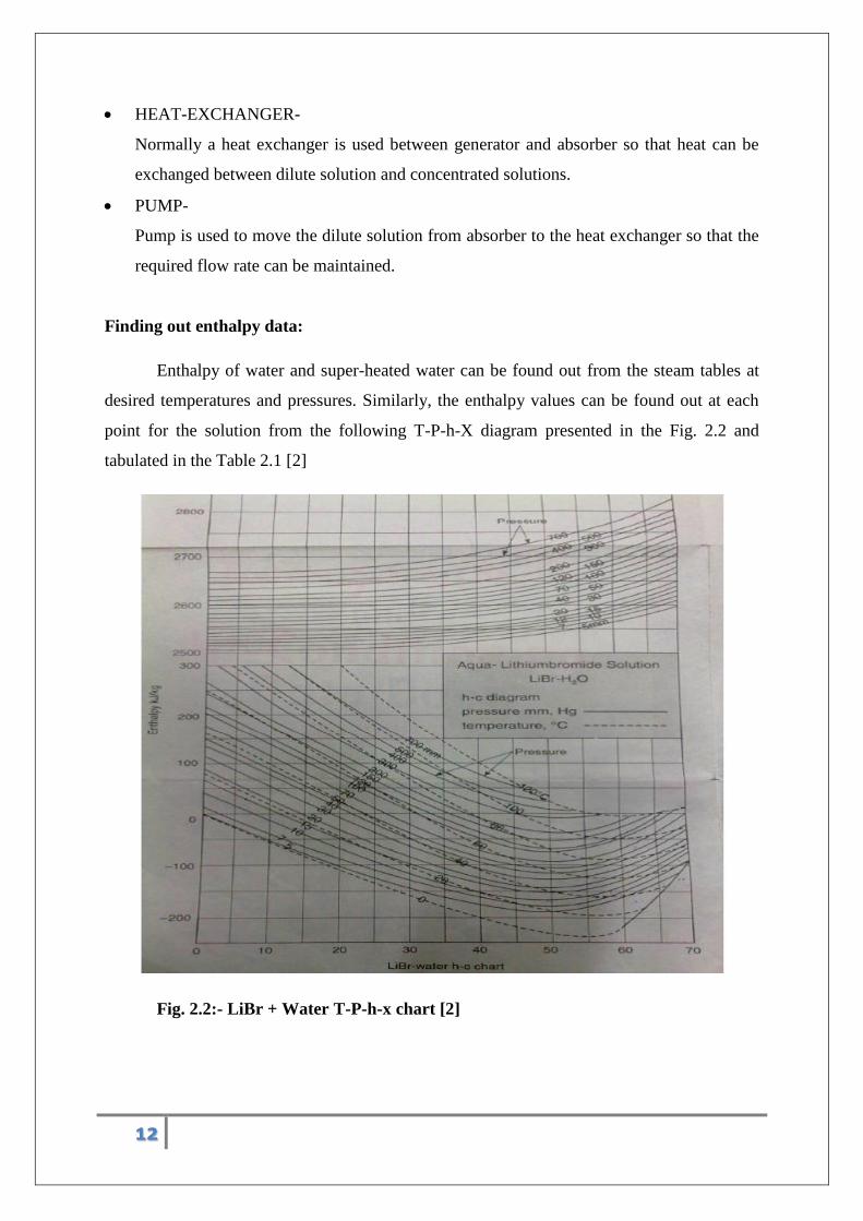
Finding out enthalpy data:
Enthalpy of water and super-heated water can be found out from the steam tables at
desired temperatures and pressures. Similarly, the enthalpy values can be found out at each
point for the solution from the following T-P-h-X diagram presented in the Fig. 2.2 and
tabulated in the Table 2.1 [2]
Fig. 2.2:- LiBr + Water T-P-h-x chart [2]
13
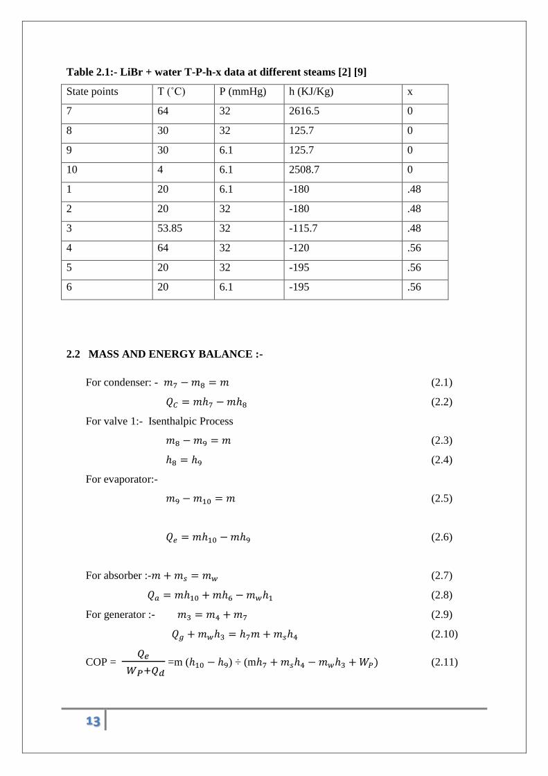
Table 2.1:- LiBr + water T-P-h-x data at different steams [2] [9]
State points T (˚C) P (mmHg) h (KJ/Kg) x
7 64 32 2616.5 0
8 30 32 125.7 0
9 30 6.1 125.7 0
10 4 6.1 2508.7 0
1 20 6.1 -180 .48
2 20 32 -180 .48
3 53.85 32 -115.7 .48
4 64 32 -120 .56
5 20 32 -195 .56
6 20 6.1 -195 .56
2.2 MASS AND ENERGY BALANCE :-
For condenser: - 𝑚7 − 𝑚8 = 𝑚 (2.1)
𝑄𝐶 = 𝑚ℎ7 − 𝑚ℎ8 (2.2)
For valve 1:- Isenthalpic Process
𝑚8 − 𝑚9 = 𝑚 (2.3)
ℎ8 = ℎ9 (2.4)
For evaporator:-
𝑚9 − 𝑚10 = 𝑚 (2.5)
𝑄𝑒 = 𝑚ℎ10 − 𝑚ℎ9 (2.6)
For absorber :-𝑚 + 𝑚𝑠 = 𝑚𝑤 (2.7)
𝑄𝑎 = 𝑚ℎ10 + 𝑚ℎ6 − 𝑚𝑤ℎ1 (2.8)
For generator :- 𝑚3 = 𝑚4 + 𝑚7 (2.9)
𝑄𝑔 + 𝑚𝑤ℎ3 = ℎ7𝑚 + 𝑚𝑠ℎ4 (2.10)
COP = 𝑄𝑒
𝑊𝑃+𝑄𝑑 =m (ℎ10 − ℎ9) ÷ (mℎ7 + 𝑚𝑠ℎ4 − 𝑚𝑤ℎ3 + 𝑊𝑃) (2.11)
14
As 𝑊𝑝 is negligible compared to 𝑄𝑔, hence it is neglected.
Coefficient of Performance of an absorption refrigeration system is obtained as;
𝐶𝑂𝑃 =𝑐𝑜𝑜𝑙𝑖𝑛𝑔 𝑐𝑎𝑝𝑎𝑐𝑖𝑡𝑦 𝑜𝑏𝑡𝑎𝑖𝑛𝑒𝑑 𝑎𝑡 𝑒𝑣𝑎𝑝𝑜𝑟𝑎𝑡𝑜𝑟
𝐻𝑒𝑎𝑡 𝑖𝑛𝑝𝑢𝑡 𝑡𝑜 𝑡ℎ𝑒 𝑔𝑒𝑛𝑒𝑟𝑎𝑡𝑜𝑟 + 𝑤𝑜𝑟𝑘 𝑖𝑛𝑝𝑢𝑡 𝑓𝑜𝑟 𝑡ℎ𝑒 𝑝𝑢𝑚𝑝=
𝑄𝑒
𝑊𝑃 + 𝑄𝑑
2.3 SAMPLE CASE STUDY :-
Using enthalpy values from Table 2.1, the energy balance can be done.
For evaporator ,
Qe = 5.25 KW = m (h10-h9) = m (2508.7 – 125.7)
Solving, the values of m= 2.203 g/s,
Circulation ratio f=Xw ÷ (Xs-Xw)
So f =0.48/(0.56-0.48) = 6
Therefore 𝒎𝒔 = 𝒇. 𝒎 =13.22 g/s
As we know 𝑚𝑤 = 𝑚𝑠 + m , hence 𝑚𝑠= 15.42 g/s
For absorber applying the energy balance ,using equation (2.8),
Hence Qa =( 2.203 × 2508.7 )+(13.22 × -196) – (15.42× -180) = 5.724 KW
For generator , Qg = m.h7 + ms.h4 –mw.h3
So Qg = (2.203× 2616.5) +( 13.22× -120) –(15.42 ×-115.7) = 5.906 KW
For condenser Qc = 2.203( 2616.5 – 125.7) =5.487 KW
COP = Qe / Qg = 5.25 / 5.906 = 0.89 .
COP = 0.89
15
CHAPTER 3:-
SIMULATION OF ABSORPTION REFRIGERATION SYSTEM
USING LiBr + WATER WORKING PAIR
16
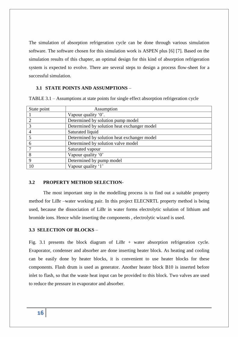
The simulation of absorption refrigeration cycle can be done through various simulation
software. The software chosen for this simulation work is ASPEN plus [6] [7]. Based on the
simulation results of this chapter, an optimal design for this kind of absorption refrigeration
system is expected to evolve. There are several steps to design a process flow-sheet for a
successful simulation.
3.1 STATE POINTS AND ASSUMPTIONS –
TABLE 3.1 – Assumptions at state points for single effect absorption refrigeration cycle
State point Assumption
1 Vapour quality ‘0’.
2 Determined by solution pump model
3 Determined by solution heat exchanger model
4 Saturated liquid
5 Determined by solution heat exchanger model
6 Determined by solution valve model
7 Saturated vapour
8 Vapour quality ‘0’
9 Determined by pump model
10 Vapour quality ‘1’
3.2 PROPERTY METHOD SELECTION-
The most important step in the modelling process is to find out a suitable property
method for LiBr –water working pair. In this project ELECNRTL property method is being
used, because the dissociation of LiBr in water forms electrolytic solution of lithium and
bromide ions. Hence while inserting the components , electrolytic wizard is used.
3.3 SELECTION OF BLOCKS –
Fig. 3.1 presents the block diagram of LiBr + water absorption refrigeration cycle.
Evaporator, condenser and absorber are done inserting heater block. As heating and cooling
can be easily done by heater blocks, it is convenient to use heater blocks for these
components. Flash drum is used as generator. Another heater block B10 is inserted before
inlet to flash, so that the waste heat input can be provided to this block. Two valves are used
to reduce the pressure in evaporator and absorber.
17
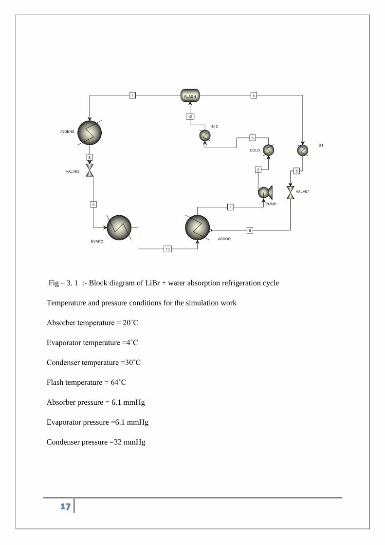
Fig – 3. 1 :- Block diagram of LiBr + water absorption refrigeration cycle
Temperature and pressure conditions for the simulation work
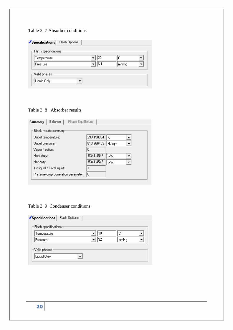
Absorber temperature = 20˚C
Evaporator temperature =4˚C
Condenser temperature =30˚C
Flash temperature = 64˚C
Absorber pressure = 6.1 mmHg
Evaporator pressure =6.1 mmHg
Condenser pressure =32 mmHg

18
Table 3. 1 evaporator condition
Table 3. 2 evaporator result
Table 3.3 flash conditions
19
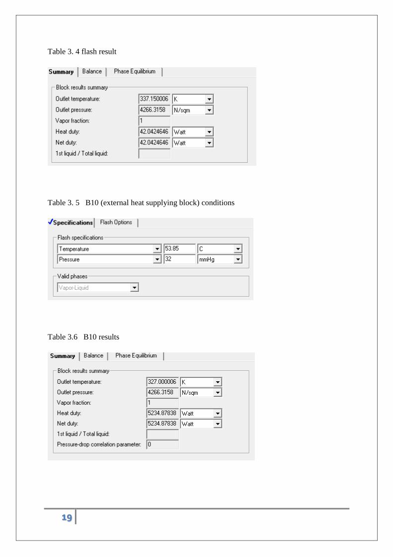
Table 3. 4 flash result
Table 3. 5 B10 (external heat supplying block) conditions
Table 3.6 B10 results
20
Table 3. 7 Absorber conditions
Table 3. 8 Absorber results
Table 3. 9 Condenser conditions
21
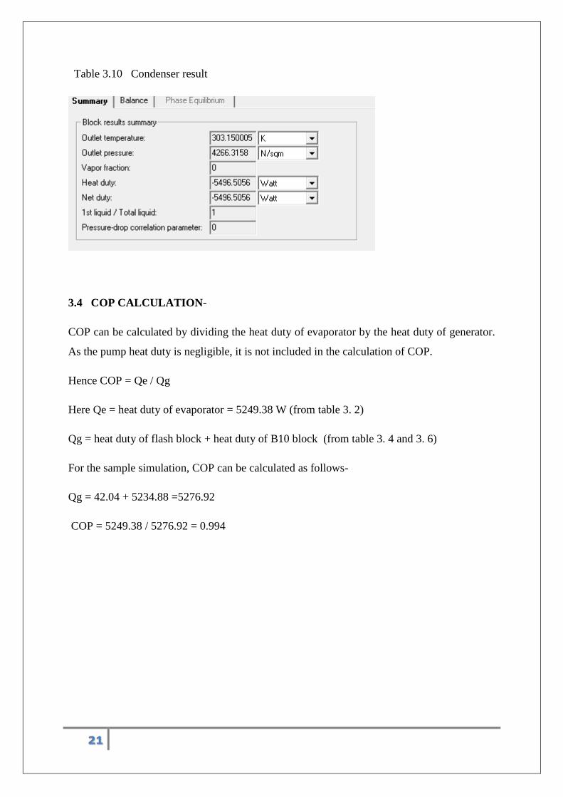
Table 3.10 Condenser result
3.4 COP CALCULATION-
COP can be calculated by dividing the heat duty of evaporator by the heat duty of generator.
As the pump heat duty is negligible, it is not included in the calculation of COP.
Hence COP = Qe / Qg
Here Qe = heat duty of evaporator = 5249.38 W (from table 3. 2)
Qg = heat duty of flash block + heat duty of B10 block (from table 3. 4 and 3. 6)
For the sample simulation, COP can be calculated as follows-
Qg = 42.04 + 5234.88 =5276.92
COP = 5249.38 / 5276.92 = 0.994
22
CHAPTER 4 :-
OPTIMIZATION , DESIGNING AND ECONOMIC FEASIBILITY
OF ABSORPTION REFRIGERATOR USING LiBr+WATER AS
WORKING PAIR
23
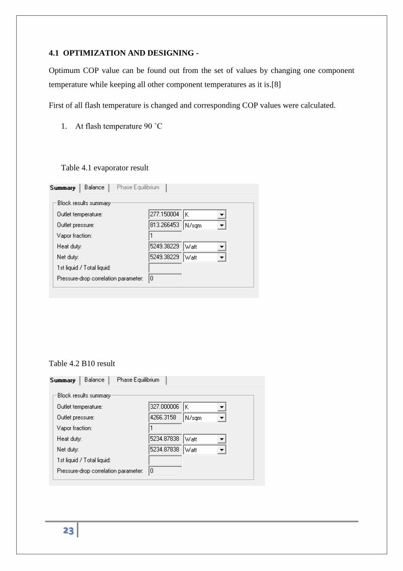
4.1 OPTIMIZATION AND DESIGNING -
Optimum COP value can be found out from the set of values by changing one component
temperature while keeping all other component temperatures as it is.[8]
First of all flash temperature is changed and corresponding COP values were calculated.
1. At flash temperature 90 ˚C
Table 4.1 evaporator result
Table 4.2 B10 result
24
Table 4. 3 flash result
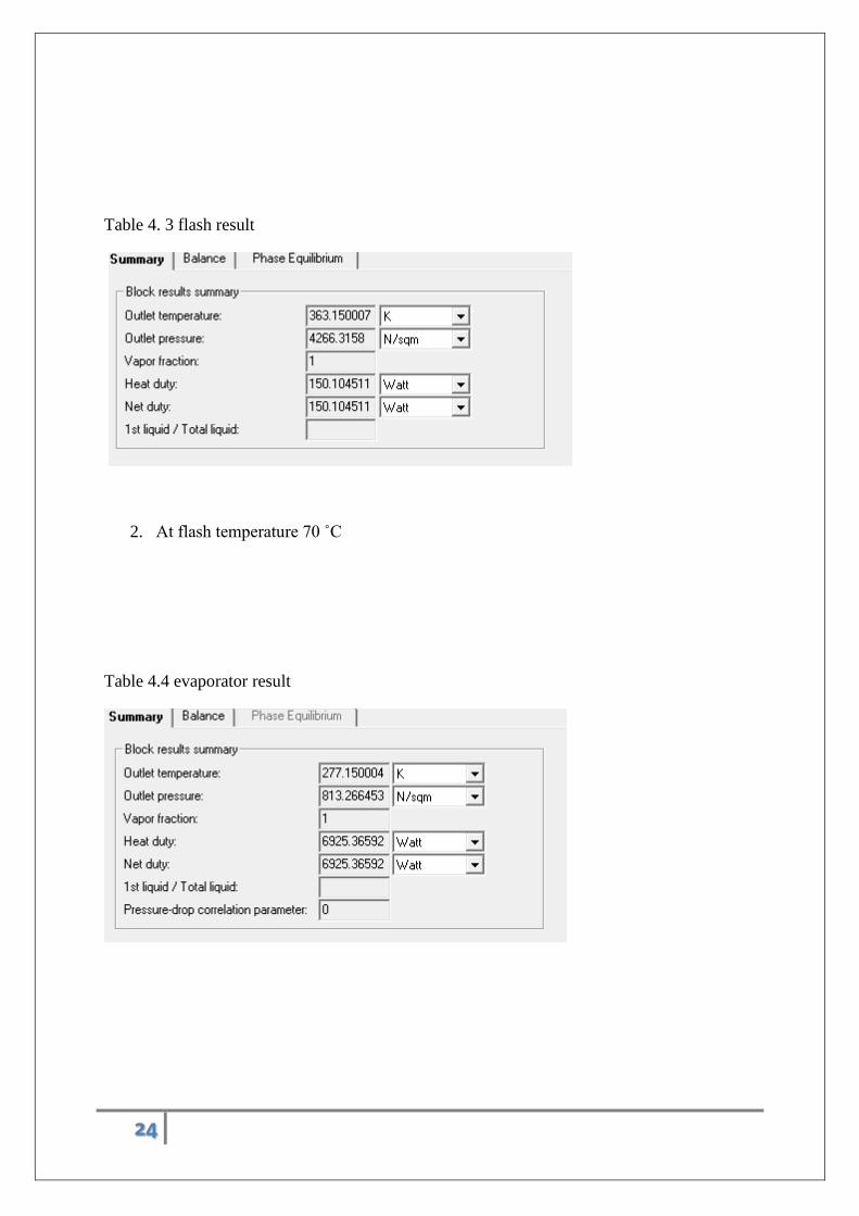
2. At flash temperature 70 ˚C
Table 4.4 evaporator result
25
Table 4.5 flash result
Table 4.6 B10 result
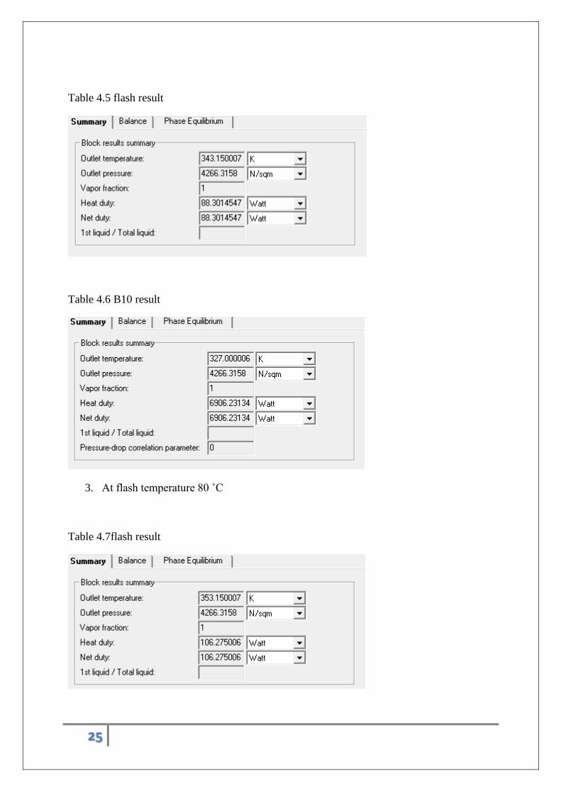
3. At flash temperature 80 ˚C
Table 4.7flash result
26
Table 4.8 evaporator result
Table Fig 4.9 B10 result
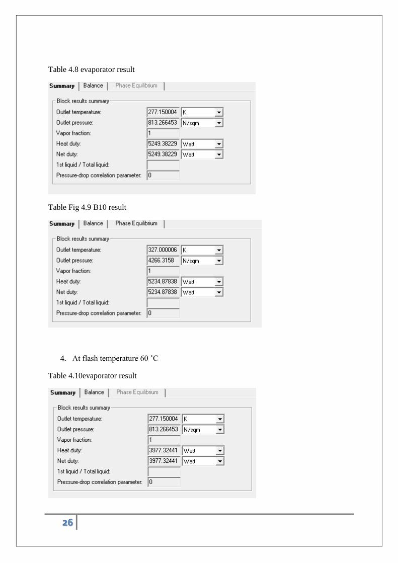
4. At flash temperature 60 ˚C
Table 4.10evaporator result
27
Table 4.11 flash result
Table 4.12 B10 result
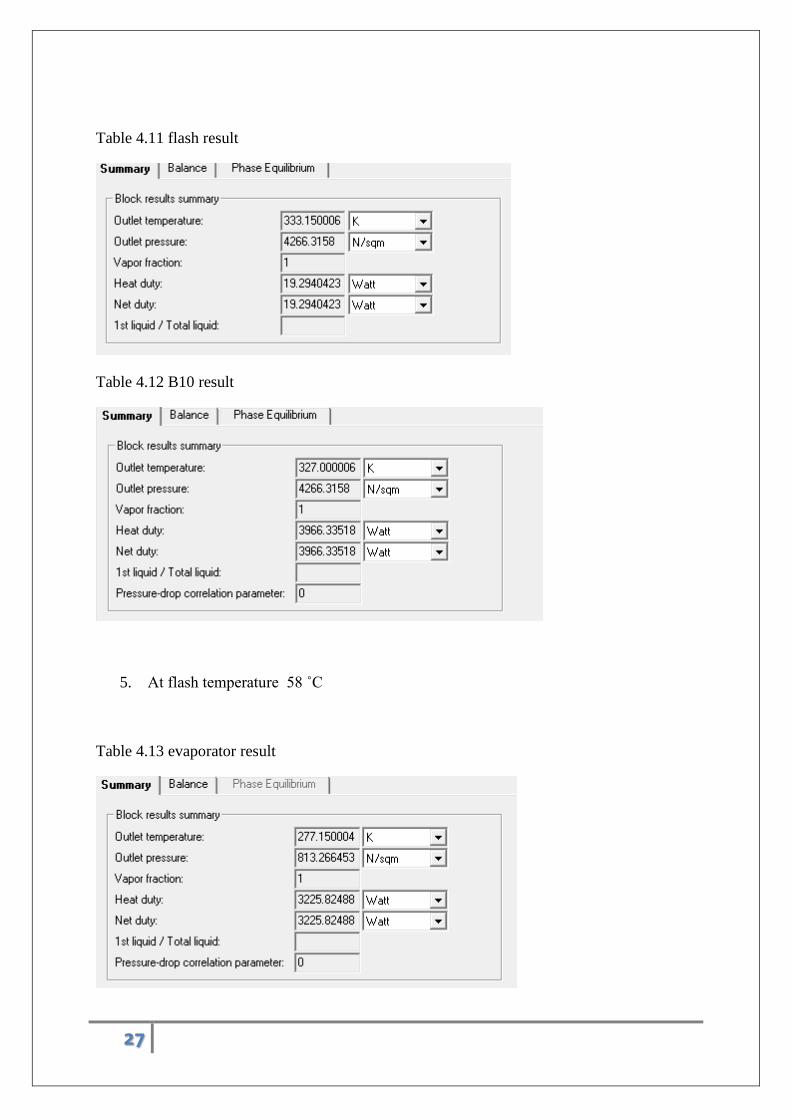
5. At flash temperature 58 ˚C
Table 4.13 evaporator result
28
Table 4.14 flash result
Table 4.15 B10 result
6. At flash temperature 55 ˚C
Table 4.16 evaporator result
29
Table 4.17 flash result
Table 4.18 B10 result
Table - 4.19 temperature of flash vs COP
Temperature(˚C) COP
90 0.975
80 0.982
70 0.990
60 0.998
58 0.999
55 1.002
30
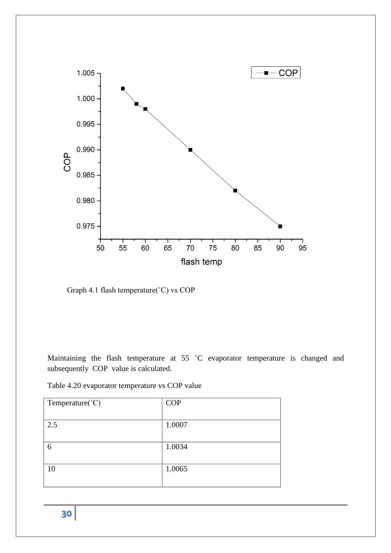
Graph 4.1 flash temperature(˚C) vs COP
Maintaining the flash temperature at 55 ˚C evaporator temperature is changed and
subsequently COP value is calculated.
Table 4.20 evaporator temperature vs COP value
Temperature(˚C) COP
2.5 1.0007
6 1.0034
10 1.0065
31
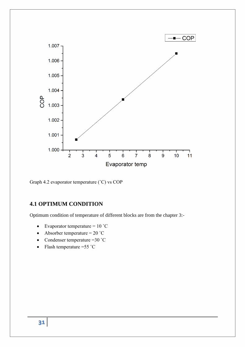
Graph 4.2 evaporator temperature (˚C) vs COP
4.1 OPTIMUM CONDITION
Optimum condition of temperature of different blocks are from the chapter 3:-
Evaporator temperature = 10 ˚C
Absorber temperature = 20 ˚C
Condenser temperature =30 ˚C
Flash temperature =55 ˚C
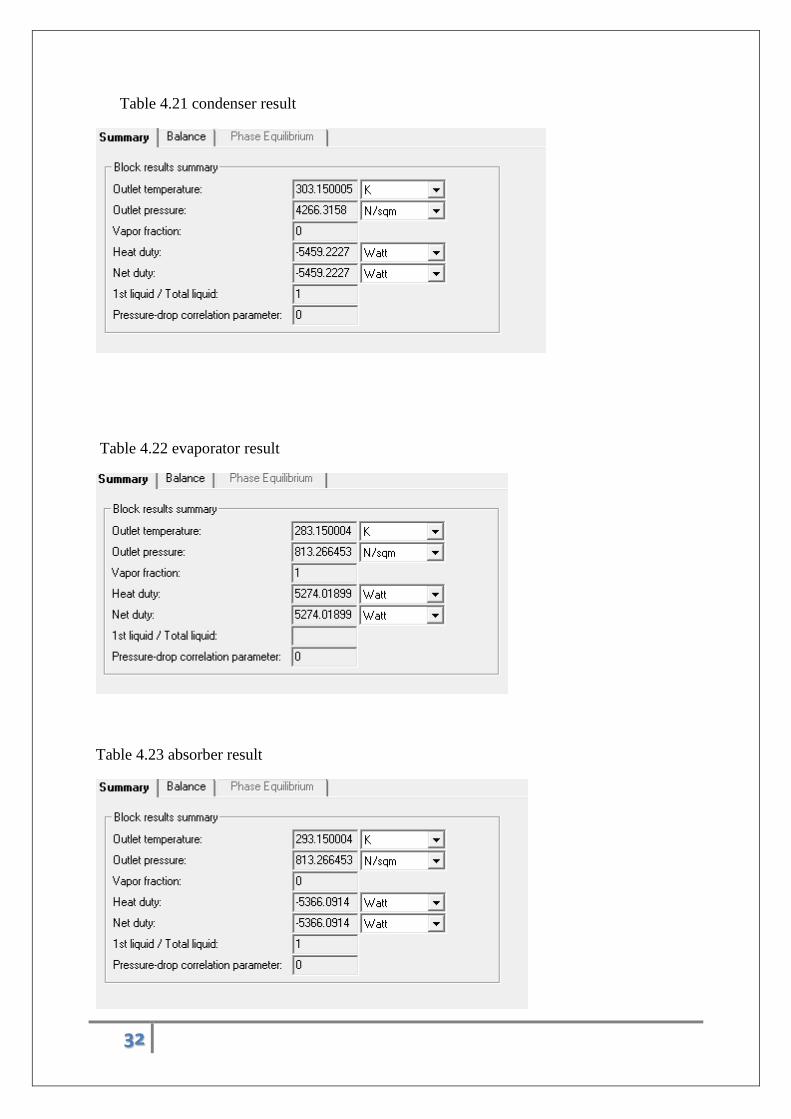
32
Table 4.21 condenser result
Table 4.22 evaporator result
Table 4.23 absorber result
33
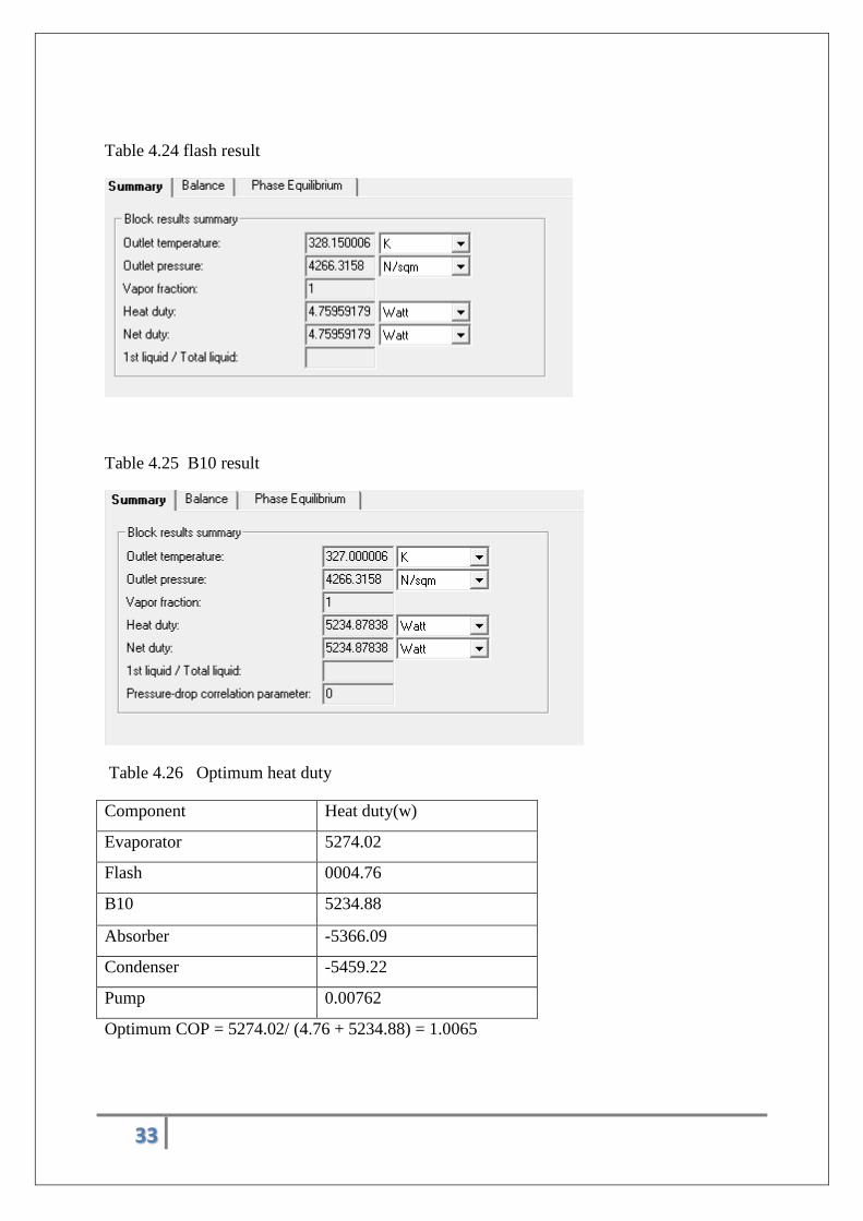
Table 4.24 flash result
Table 4.25 B10 result
Table 4.26 Optimum heat duty
Component Heat duty(w)
Evaporator 5274.02
Flash 0004.76
B10 5234.88
Absorber -5366.09
Condenser -5459.22
Pump 0.00762
Optimum COP = 5274.02/ (4.76 + 5234.88) = 1.0065
34
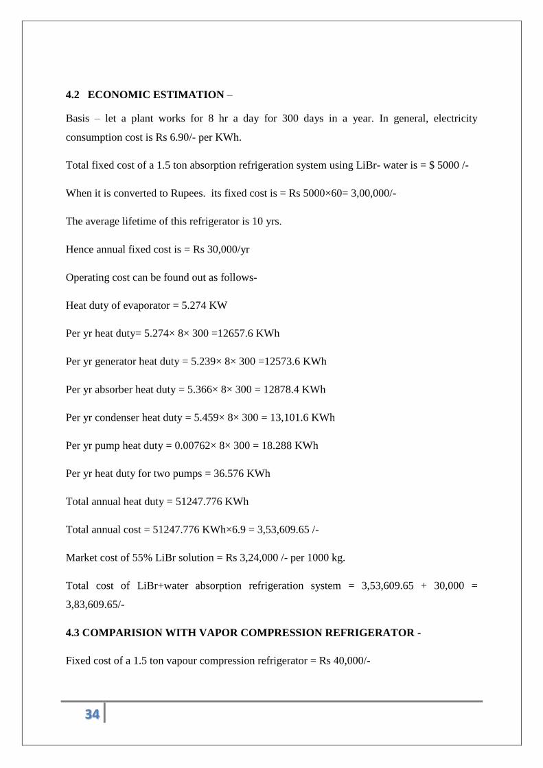
4.2 ECONOMIC ESTIMATION –
Basis – let a plant works for 8 hr a day for 300 days in a year. In general, electricity
consumption cost is Rs 6.90/- per KWh.
Total fixed cost of a 1.5 ton absorption refrigeration system using LiBr- water is = $ 5000 /-
When it is converted to Rupees. its fixed cost is = Rs 5000×60= 3,00,000/-
The average lifetime of this refrigerator is 10 yrs.
Hence annual fixed cost is = Rs 30,000/yr
Operating cost can be found out as follows-
Heat duty of evaporator = 5.274 KW
Per yr heat duty= 5.274× 8× 300 =12657.6 KWh
Per yr generator heat duty = 5.239× 8× 300 =12573.6 KWh
Per yr absorber heat duty = 5.366× 8× 300 = 12878.4 KWh
Per yr condenser heat duty = 5.459× 8× 300 = 13,101.6 KWh
Per yr pump heat duty = 0.00762× 8× 300 = 18.288 KWh
Per yr heat duty for two pumps = 36.576 KWh
Total annual heat duty = 51247.776 KWh
Total annual cost = 51247.776 KWh×6.9 = 3,53,609.65 /-
Market cost of 55% LiBr solution = Rs 3,24,000 /- per 1000 kg.
Total cost of LiBr+water absorption refrigeration system = 3,53,609.65 + 30,000 =
3,83,609.65/-
4.3 COMPARISION WITH VAPOR COMPRESSION REFRIGERATOR -
Fixed cost of a 1.5 ton vapour compression refrigerator = Rs 40,000/-
35
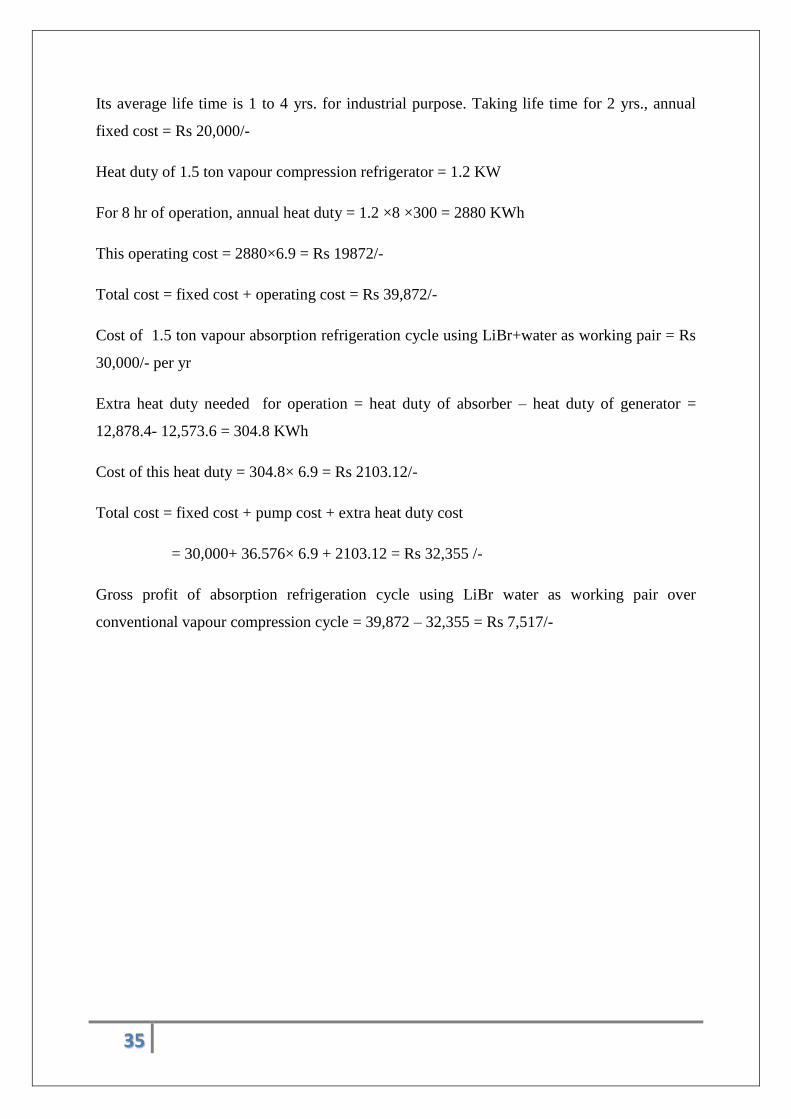
Its average life time is 1 to 4 yrs. for industrial purpose. Taking life time for 2 yrs., annual
fixed cost = Rs 20,000/-
Heat duty of 1.5 ton vapour compression refrigerator = 1.2 KW
For 8 hr of operation, annual heat duty = 1.2 ×8 ×300 = 2880 KWh
This operating cost = 2880×6.9 = Rs 19872/-
Total cost = fixed cost + operating cost = Rs 39,872/-
Cost of 1.5 ton vapour absorption refrigeration cycle using LiBr+water as working pair = Rs
30,000/- per yr
Extra heat duty needed for operation = heat duty of absorber – heat duty of generator =
12,878.4- 12,573.6 = 304.8 KWh
Cost of this heat duty = 304.8× 6.9 = Rs 2103.12/-
Total cost = fixed cost + pump cost + extra heat duty cost
= 30,000+ 36.576× 6.9 + 2103.12 = Rs 32,355 /-
Gross profit of absorption refrigeration cycle using LiBr water as working pair over
conventional vapour compression cycle = 39,872 – 32,355 = Rs 7,517/-
36
CHAPTER 5 CONCLUSIONS AND FUTURE RECOMMENDATIONS
37
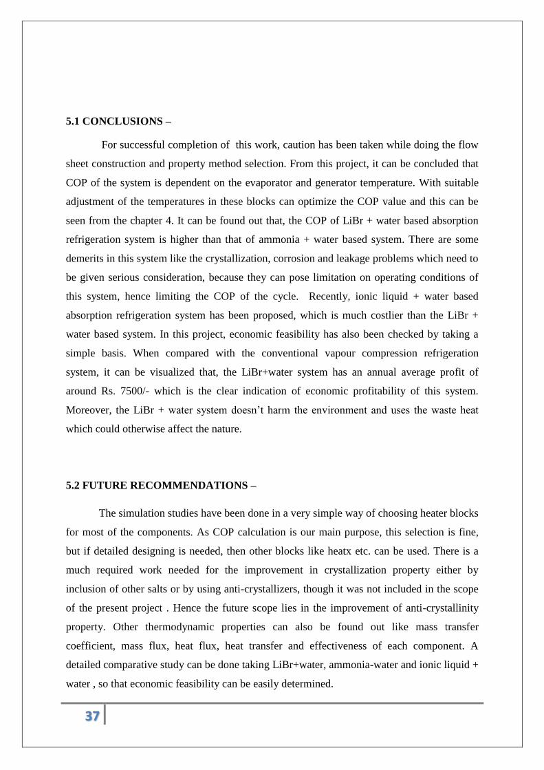
5.1 CONCLUSIONS –
For successful completion of this work, caution has been taken while doing the flow
sheet construction and property method selection. From this project, it can be concluded that
COP of the system is dependent on the evaporator and generator temperature. With suitable
adjustment of the temperatures in these blocks can optimize the COP value and this can be
seen from the chapter 4. It can be found out that, the COP of LiBr + water based absorption
refrigeration system is higher than that of ammonia + water based system. There are some
demerits in this system like the crystallization, corrosion and leakage problems which need to
be given serious consideration, because they can pose limitation on operating conditions of
this system, hence limiting the COP of the cycle. Recently, ionic liquid + water based
absorption refrigeration system has been proposed, which is much costlier than the LiBr +
water based system. In this project, economic feasibility has also been checked by taking a
simple basis. When compared with the conventional vapour compression refrigeration
system, it can be visualized that, the LiBr+water system has an annual average profit of
around Rs. 7500/- which is the clear indication of economic profitability of this system.
Moreover, the LiBr + water system doesn’t harm the environment and uses the waste heat
which could otherwise affect the nature.
5.2 FUTURE RECOMMENDATIONS –
The simulation studies have been done in a very simple way of choosing heater blocks
for most of the components. As COP calculation is our main purpose, this selection is fine,
but if detailed designing is needed, then other blocks like heatx etc. can be used. There is a
much required work needed for the improvement in crystallization property either by
inclusion of other salts or by using anti-crystallizers, though it was not included in the scope
of the present project . Hence the future scope lies in the improvement of anti-crystallinity
property. Other thermodynamic properties can also be found out like mass transfer
coefficient, mass flux, heat flux, heat transfer and effectiveness of each component. A
detailed comparative study can be done taking LiBr+water, ammonia-water and ionic liquid +
water , so that economic feasibility can be easily determined.
38
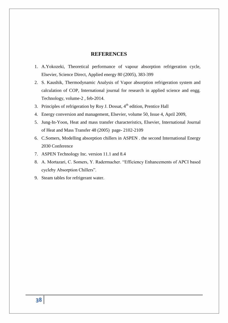
REFERENCES
1. A.Yokozeki, Theoretical performance of vapour absorption refrigeration cycle,
Elsevier, Science Direct, Applied energy 80 (2005), 383-399
2. S. Kaushik, Thermodynamic Analysis of Vapor absorption refrigeration system and
calculation of COP, International journal for research in applied science and engg.
Technology, volume-2 , feb-2014.
3. Principles of refrigeration by Roy J. Dossat, 4th
edition, Prentice Hall
4. Energy conversion and management, Elsevier, volume 50, Issue 4, April 2009,
5. Jung-In-Yoon, Heat and mass transfer characteristics, Elsevier, International Journal
of Heat and Mass Transfer 48 (2005) page- 2102-2109
6. C.Somers, Modelling absorption chillers in ASPEN . the second International Energy
2030 Conference
7. ASPEN Technology Inc. version 11.1 and 8.4
8. A. Mortazari, C. Somers, Y. Radermacher. “Efficiency Enhancements of APCI based
cycleby Absorption Chillers”.
9. Steam tables for refrigerant water.

39