design of sketch-based interface to enhance creativity in
TRANSCRIPT
Design Issues International Design Journal Volume 4 Issue 2
261
Design of sketch-based interface to enhance creativity in conceptual design
Dr. Islam Gharib
Faculty of Applied Arts, Helwan University, Cairo, Egypt
Abstract Sketching is a common method used in conceptual design. Its ambiguity inspires designers with new and unexpected alternatives for design ideas which enhance creativity in conceptual design. Sketch-based modeling appeared as an easy way for 3D sketching to open the way for digitizing sketching process. For that reason it focused on developing techniques and algorithms of converting 2D sketches into 3D models rather than enhancing creativity in sketching process. In this paper we present a new design for a sketch-based modeling interface to enhance creativity by considering sketching as an idea generation method, not a drawing process. This was done by separating 2D sketching and 3D modeling into two windows to make designers focus on idea development rather than being distrusted by 3D model creation. This interface uses gesture-based approach in 3D modeling as this approach is better for achieving integration with commercial CAD systems for more effectiveness of sketch-based interfaces. A new positioning method was developed to help designers to locate 3D objects in the scene easily with friendlier gestures and more accurate gesture recognition algorithm.
Keywords: sketch, sketch-based modeling, conceptual design, creativity, gesture recognition
1 Introduction The ultimate goal of the conceptual design stage is to find a solution for an existing problem, investigate design space, or explore an idea. All these tasks require thinking, imagination, and creativity which lead for innovative design. Designers use different methods to perform these tasks but the most common method is sketching because it is very simple, easy to use, cheap, and gives immediate feedback for their ideas. This feedback is important in idea generation process because it helps designers to spot errors in ideas and correct them. According to Ferguson (Ferguson, 1994), there are three kinds of sketches: the thinking sketch, the perspective sketch, and the talking sketch. The thinking sketch is used to focus and guide non-verbal thinking or idea generation. The perspective sketch is used to direct draftsman in making a finished drawing. The talking sketch is used in exchange between technical people. In conceptual design, designers use the thinking sketch to explore ideas. With the appearance of CAD systems, there was a thought that it could be used in sketching as well as detailed design. But with the actual experience, designers abstained from using CAD systems to sketch and still do sketching using pencil and paper. This is because CAD systems require a high level of accuracy and also because sketching needs an easy, fast, and intuitive way
to express ideas that arising quickly in mind. Later, sketch-based modeling was developed to serve sketching process. The aim of sketch-based modeling is to convert 2D freehand sketches to 3D models. Researchers developed two main approaches: reconstruction and gesture-based modeling. The reconstruction approach attempts to extract 3D models from 2D freehand sketches. This technique works with two types of sketches: single line drawing and over-traced sketches. In the case of over-traced sketches, beautification algorithms are applied to convert it into a single line drawing and then reconstruct the 3D models. This means sketches should be simple; don’t contain other elements such as assistant lines, drawings on side view, sections, or annotations. This is in contrast to the thinking sketches that are used in idea generation. The other approach, gesture-based modeling, uses predefined gestures to create predefined 3D models. These models vary from primitives to freeform. It can be considered a simplified version of traditional CAD systems which uses gestures instead of menus and buttons. Users concentrate on gesture drawing process to draw it correctly first and to place it accurately in the right place. This interrupts their concentration on idea generation because ideas are not complete in minds. In this paper, we present a friendlier 3D
International Design Journal Volume 4 Issue 2 Design Issues
262
sketching interface for conceptual design. This interface is to serve the needs of designers in idea generation process. It works through two windows, one for 2D sketching that enhance creativity of the designer and the other is for 3D modeling that generates quick and rough 3D models via sketch gestures. This kind of interface with two windows is to help users to concentrate on their task at both the idealization process and the rapid 3D modeling process. The user begins with 2D sketching that mimic the pencil-and-paper to visualize his/her imagined ideas. This gives the user immediate feedback, so he can edit it, remove or add details, write notes about materials, or draw sections to explain what is inside the object. This interactive process is the corner stone in developing ideas in conceptual design. After that the user can use these 2D sketches or part of it to convert them into 3D models, but the question is which approach should be used to do this process, reconstruction or gesture-based modeling. Reconstruction approach may be more convenient for users but it produces flat 3D information. On the other hand gesture-based modeling produces more precise 3D information as it is feature-based designs similar to commercial CAD systems. For that reason, our 3D modeling window uses gestures for modeling. Users use their 2D sketches as reference images in the 3D modeling window. This allows them to have knowledge of the proportions. Then, by over drawing gestures, they create rough 3D models. As positioning is one of common problems in sketch-based modeling, we developed a new multi-controlled reference plane system to locate 3D objects in the scene. This system allows user to manipulate reference planes freely and accurately. The user can create, locate, and remove reference planes in directions that give him a good ability to draw in 3D. A new algorithm for gesture recognition was developed containing three levels for more accurate recognition and more easiness in drawing gestures. Another feature of this system is producing an IGES file to integrate with existing CAD systems. This can reduce time consumed in the detailed design stage. This paper is organized as follows. The next section reviews related works on sketching as a creative method for generating idea, and sketch-based modeling. In section 3, a questionnaire study about sketching behavior and sketch-based interfaces preferences is described. Section 4 describes the interface design. Section 5 contains
two case studies that we conducted to show the easiness and intuition of the sketching process and to investigate the verity of 3D models that can be created. In section 6, we conducted a user study to evaluate gesture design, idea generation process, and 3D modeling. Section 7 contains conclusion and future work respectively.
2 Related works This section is divided into two aspects: work related to sketching process and the other related to sketch-based modelling.
2.1 Sketching process Sketching ideas is different from ‘drawing from the object’ (Tovey et al., 2003). It is not drawing of something that already exists. Sketches are a representation of something that is imagined in the mind of the designer. Ferguson (Ferguson, 1994) differed between three kinds of sketches: (1) the thinking sketch, (2) the perspective sketch, and (3) the talking sketch. This paper concentrates on the thinking sketch which is used to focus and guide non-verbal thinking as it is the one the designer use in idea generation process. Sketching process has two activities that a designer practices: mental activities and technical activities. The mental activities contains cognitive and imagination activities, while technical activities are related to sketching behavior, tools, and graphical representation. As a mental activity, sketching is related to some key terms such as thinking, imagining, visual thinking, and visual imagination. Thinking is the way that our brains realize and order information and thoughts (Tovey, 1989). A designer receives visual information by seeing and imagination uses this information in creating virtual visual information inside the brain. Visual thinking organizes these pieces of information together to construct a ‘virtual world’ in the mind of the designer (Schön and DeSanctis, 1986). Designers use sketching to visualize this imagined visual information on paper. This is why sketches are considered an extension of imagination and an external representation of imagined objects (Tevrsky, 2008; Goldschmidt, 1991; Römer, 2001). And as the flow of ideas is quick and instantaneous, the designer uses sketching to record his ideas quickly for more inspections (Tevrsky, 2008). Sketching offers a kind of circular feedback loop in this process between two kinds of pictorial representation: internal representation in imaginary and external representation on paper (Goldschmidt, 2003). While a designer draws, he
Design Issues International Design Journal Volume 4 Issue 2
263
sees what he has drawn and discovers features and relations in his drawing (Schon and Wiggins, 1992). This kind of mental iteration is suggested also in (Maher et al., 1996; Adam and Atman, 1999). In this point thinking is integrated with imagination because a designer thinks about features and relations, and then starts to imagines how to develop them. Ambiguity of sketches plays a key role in this feedback process (van Dijk, 1992). As sketches are freehand drawing and lines are drawn uncertainly, it inspires the designer with alternative solution (Scrivener et al., 2000). This is because the line can be interpreted in different ways and this is one of the strength of sketches in enhancing creativity. Sketching as a graphical activity is more related to graphical features and tools which are used by designers through sketching process. A sketchpad with pencils is the common used medium in sketching because it allows a continuous sequence and the production of many ideas in a short time (Schon, 1999; Tovey, 1989). Graphical appearance of sketches is usually loose and informal and has a much amount of ambiguity. Graphical elements of sketches can be divided into two categories: physical and perceptual (Suwa et al., 1998). Physical category is related to the visual description of the element such as a line, circle, arrow, or word. The perceptual category is related to how the designer perceives the graphical elements such as shapes, sizes, and textures. For example, a set of lines can be perceived as a rectangle. Graphical elements specify the complexity of the sketch. Tovey (Tovey, 1989) define two levels of details in sketches: detailed and undetailed. The undetaied sketches contain abstract and general concept drawings and the detailed sketches contain in addition to that a part drawing. This simple model is not enough to describe the graphical side of the sketch precisely, so it was expanded in (Tovey et al., 2003) to a model of five level of complexity. According to that model, there are five levels of complexity in sketches. This kind of studies of graphical aspects of sketches is important to the sketch-based systems developers because they give clear ideas about drawing features that systems should work with to produce 3D models. For that reason, in our previous study (Gharib & Qin, 2010), we analysis 70 sketches to find out if designers use some specific graphical features in sketches in the same way or not. This analysis was based on six graphical features: (1) 2D drawing, (2) 3D
drawing, (3) shading, (4) coloring, (5) assistant lines, and (6) annotations. Results showed that that novice and professional designers use same graphical, geometrical, and assistant features in sketching but slight difference according to ideas and skills. Also, it was noticed that most sketches contain more than one idea or concept which may refers to how ideas may be generated within the sketch. Although this study gave us precise information about using of graphical features in sketching but more research is needed about how a designer behaves graphically through his sketching.
2.2 Sketch-based modeling Thinking in sketching digitization started decades ago with SketchPad presented by Sutherland (Sutherland, 1964). From this date, a body of work was presented to enhance this direction of research. Sketch-based modeling is the title now used to refer to the sketching digitization. Sketch-based modeling can be divided into two categories based on the approach used: reconstruction-based and gesture-based. It also can be classified according to the domain it serves. In general, sketch-based modeling ultimate goal is to convert 2D sketches to 3D models. Reconstruction-based approach began earlier than gesture-based approach using previous knowledge of offline line drawing recognition. Gesture-based approach needs for gesture recognition engines to recognize gestures codes but this didn’t prevent several works of being presented using this approach. In this paper we concentrate on gesture-based modeling as we use gestures to create 3D models within the system we present here. Although GRANDMA (Rubine, 1991) was one of the first systems presented for gesture recognition in 1991 but SKETCH (Zeleznik et al., 1996) is considered the most expressing example of gesture-based modeling. SKETCH is designed to create 3D geometrical objects using gestures that inspired by combining some features of pencil-and-paper and some features of CAD systems. The limited variety of 3D objects produced by SKETCH was one of its limitations. This is because of the need to a larger number of gestures which need robust algorithms to recognize them. Chateau (Igarashi & Hughes, 2001) presented a suggestive interface to solve this problem. This suggestive interface gives the user hints about the desired operations which makes the job of gesture
International Design Journal Volume 4 Issue 2 Design Issues
264
recognition algorithms easier. For freeform modeling, Teddy (Igarashi et al., 1999) was presented as a simple freeform creation method. The user inputs a closed stroke and the system creates a 3D shape matching this contour automatically. This object can be edited through extrusion or cutting but to create a new object the user should start from the beginning. Teddy’s approach was extended for more complex 3D objects by Karpenko et al. (Karpenko et al., 2002). This work allows user to create more than one objects, connect them together, and allows more editing facilities. Because of the limitation of SKETCH and Teddy, ShapeShop (Schmidt et al., 2006) attempted to combine between the geometrical modeling showed in SKETCH and the freeform modeling showed in Teddy to overcome the limitation of variety in 3D objects created. It used extrusion, revolution, and freeform modeling to create 3D objects. Also, it used several editing techniques to manipulate objects created. The main problem in the gesture-based approach is how to recognize gestures entered by the user to construct the right 3D object. For that reason, some works focused on developing robust algorithms for gesture recognition (Gonen & Akleman, 2011; Alvarado, 2004; Alvarado & Davis, 2004). But as algorithms are usually connected to gestures used, developers began to develop gesture-based systems which serve specific domains such as human modeling (Mao et al., 2009), and clothing design (Wenpeng and Xiaohuang, 2010). Works reviewed related to sketching process provide precise information about the mental and graphical aspects of sketching. Also, works related to sketch-based modeling presented good examples for sketch-based interfaces but it can be noticed that they concentrated on solving problems within the technical part of the job rather than being concerned by how the system will work in real life. They considered sketching as a drawing process in 3D where the user has the complete idea in mind and just draws it. This point of view ignores that sketching is a representation of thinking and imagination processes and expressing about ideas comes later by sketching them on paper. Putting ideas on paper is done for different purposes such as recording ideas for more thinking, communication or presentation to others. This is why in this paper we focus on the interaction between designers and the sketching interface.
We also concentrate on understanding the behavior of the designer through sketching to present a sketch-based interface which is friendlier for designers and fulfills the real requirements of conceptual design stage. On the other hand, it is noticeable that sketch-based interfaces are isolated from CAD, CAM systems because there is no kind of integration between them as the sketch-based modeling is still in developing stage in comparison to CAD systems. But there is few attempts to develop an integration between sketch-based systems and CAD systems to offer a way for designers to use their 3D sketches in detailed design stage such as (Cheon et al., 2011). This work presented a method for integration using macro file format whit a gesture-based modeling approach. Using of the macro format limits the benefits of this method which can be expanded with the using of a more complex file format as the IGES which can support several of 3D models representation.
3 Questionnaire study The aim of this questionnaire study is to collect more information about how a designer sketches, what a strategy he uses, and what essential graphical features his sketches contain. It also aims to find out what a designer prefer about sketch-based interfaces. The importance of this study is related to the need to study sketching behavior combined with the graphical side of sketching. This helps in more understanding for sketching process especially when it is connected to the development of sketch-based interface that can support creativity within sketching. This questionnaire was distributed between design students, design researchers, and designers. It was distributed online and invitations were sent to participants via e-mail. 69 responds were received, 37 males, and 32 females. Participants are divided as follows: 27 design student, 5 design researchers, and 29 designers. Most of designers work in product and industrial design discipline.
3.1 The design of the questionnaire This questionnaire is divided into two sections. The first section contains questions related to sketching behavior. The second section includes questions about designers’ preferences about sketch-based systems. In the first section, participants were asked about five categories of information to provide: (1) tools or medium used in sketching, (2) ideation process, (3) graphical features, (4) geometrical features, and (5) assisting elements. Tools of medium used in
Design Issues International Design Journal Volume 4 Issue 2
265
sketches are pencil-and-paper, colors-and-paper, or CAD systems. Ideation process means how many ideas the participant normally visualizes before reaching the final idea and how many ideas he draws in the same piece of paper. Graphical features include shading, drop shading, coloring, and annotations. These graphical features play a key role in realism of sketches. In this study, geometrical features describe the way of drawing, 2D or 3D. For example, a designer draws an object in perspective, so he uses the 3D drawing. Assisting elements express about elements that are used to help designers to draw the final shape of the object, such as assistant lines, or using 2D drawing to draw perspective. This information is important to understand sketch’s contains which help in designing the sketch-based system. In the second section, as sketch-based systems are not popular commercially, participants asked
to watch two videos about Teddy (Igarashi et al., 1999) and SKETCH (Zeleznik et al., 1997) to have a brief idea about this kind of systems if they have never used one. After watching the videos, participants gave answers about their previous experience with CAD or sketch-based systems. They also gave information about what they think it will be preferable for developing a new sketch-based system that serve the conceptual design stage in product design field. They chose answers between three choices: yes, no, or not sure. This way of choosing specific answers helps in getting specific opinions.
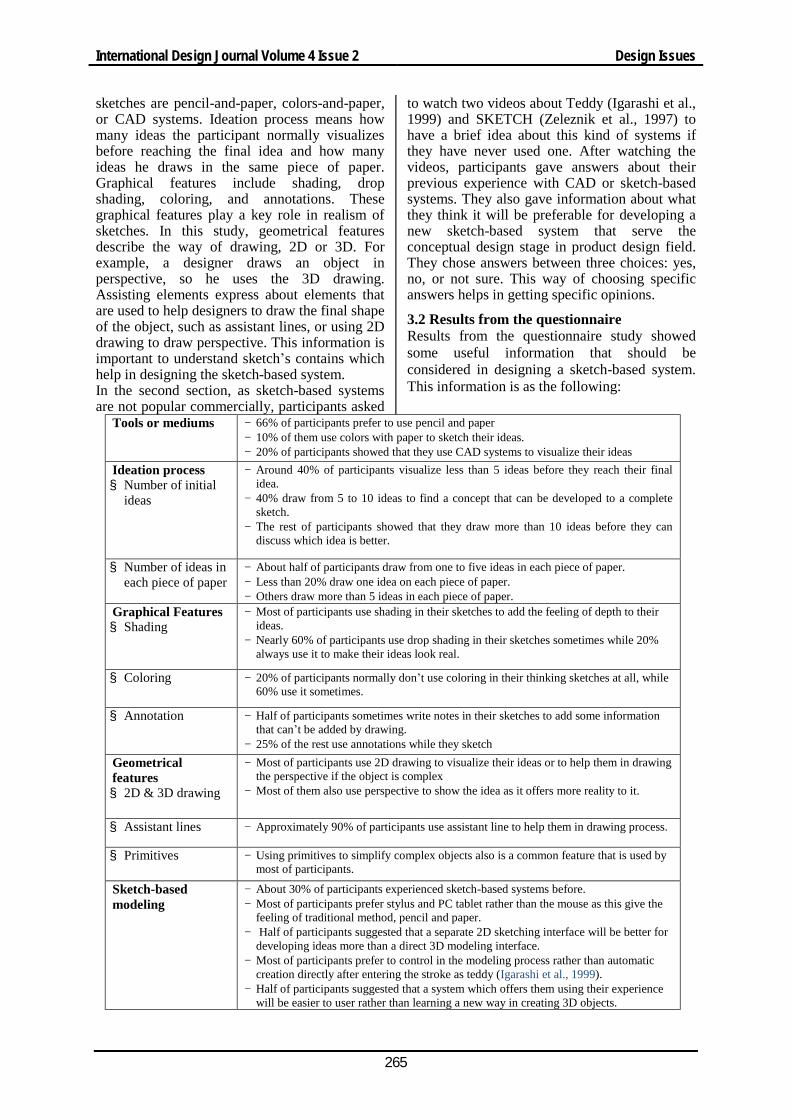
3.2 Results from the questionnaire Results from the questionnaire study showed some useful information that should be considered in designing a sketch-based system. This information is as the following:
Tools or mediums − 66% of participants prefer to use pencil and paper − 10% of them use colors with paper to sketch their ideas. − 20% of participants showed that they use CAD systems to visualize their ideas
Ideation process § Number of initial
ideas
− Around 40% of participants visualize less than 5 ideas before they reach their final idea.
− 40% draw from 5 to 10 ideas to find a concept that can be developed to a complete sketch.
− The rest of participants showed that they draw more than 10 ideas before they can discuss which idea is better.
§ Number of ideas in each piece of paper
− About half of participants draw from one to five ideas in each piece of paper. − Less than 20% draw one idea on each piece of paper. − Others draw more than 5 ideas in each piece of paper.
Graphical Features § Shading
− Most of participants use shading in their sketches to add the feeling of depth to their ideas.
− Nearly 60% of participants use drop shading in their sketches sometimes while 20% always use it to make their ideas look real.
§ Coloring − 20% of participants normally don’t use coloring in their thinking sketches at all, while 60% use it sometimes.
§ Annotation − Half of participants sometimes write notes in their sketches to add some information that can’t be added by drawing.
− 25% of the rest use annotations while they sketch Geometrical features § 2D & 3D drawing
− Most of participants use 2D drawing to visualize their ideas or to help them in drawing the perspective if the object is complex
− Most of them also use perspective to show the idea as it offers more reality to it.
§ Assistant lines − Approximately 90% of participants use assistant line to help them in drawing process.
§ Primitives − Using primitives to simplify complex objects also is a common feature that is used by most of participants.
Sketch-based modeling
− About 30% of participants experienced sketch-based systems before. − Most of participants prefer stylus and PC tablet rather than the mouse as this give the
feeling of traditional method, pencil and paper. − Half of participants suggested that a separate 2D sketching interface will be better for
developing ideas more than a direct 3D modeling interface. − Most of participants prefer to control in the modeling process rather than automatic
creation directly after entering the stroke as teddy (Igarashi et al., 1999). − Half of participants suggested that a system which offers them using their experience
will be easier to user rather than learning a new way in creating 3D objects.
International Design Journal Volume 4 Issue 2 Design Issues
266
From previous results, it is apparent that pencil-and-paper is still the most common method used by designers to sketch. Also, most of designers draw many ideas before they get the final idea. Through drawing of these ideas, developing process for ideas is done and here creativity plays a key role in reaching into an innovative design. It is also clear that stylus and PC tablet is a preferable method rather than the mouse. Free 2D sketching before 3D modeling is suggested to help designers in developing ideas in the conceptual design stage.
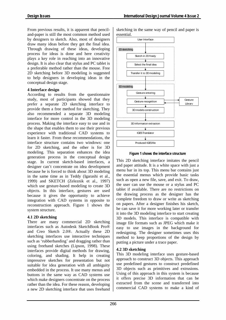
4 Interface design According to results from the questionnaire study, most of participants showed that they prefer a separate 2D sketching interface to provide them a free method for sketching. They also recommended a separate 3D modeling interface for more control in the 3D modeling process. Making the interface easy to use and in the shape that enables them to use their previous experience with traditional CAD systems to learn it faster. From these recommendations, the interface structure contains two windows: one for 2D sketching, and the other is for 3D modeling. This separation enhances the idea generation process in the conceptual design stage. In current sketch-based interfaces, a designer can’t concentrate on idea development because he is forced to think about 3D modeling in the same time as in Teddy (Igarashi et al., 1999) and SKETCH (Zeleznik et al., 1997) which use gesture-based modeling to create 3D objects. In this interface, gestures are used because it gives the opportunity to achieve integration with CAD systems in opposite to reconstruction approach. Figure 1 shows the system structure.
4.1 2D sketching There are many commercial 2D sketching interfaces such as Autodesk SketchBook Pro® and Creo Sketch 2.0®. Actually these 2D sketching interfaces use interactive techniques such as ‘rubberbanding’ and dragging rather than using freehand sketches (Lipson, 1998). These interfaces provide digital methods for drawing, coloring, and shading. It help in creating impressive sketches for presentation but not suitable for idea generation with all ambiguity embedded in the process. It use many menus and buttons in the same way as CAD systems use which make designers concentrate on the process rather than the idea. For these reason, developing a new 2D sketching interface that uses freehand
sketching in the same way of pencil and paper is essential.
User Interface
2D sketching
3D modeling
Gesture entering
Gesture recognition
3D models construc on
Gesture Library
3D informa on extrac on
IGES Translator
Produced IGES file
Sketch in 2D freely
Select the final idea
Transfer it to 3D modeling
Figure 1 shows the interface structure
This 2D sketching interface imitates the pencil and paper attitude. It is a white space with just a menu bar in its top. This menu bar contains just the essential menus which provide basic tasks such as open a new file, save, and exit. To draw, the user can use the mouse or a stylus and PC tablet if available. There are no restrictions on the drawing process as the designer has the complete freedom to draw or write as sketching on papers. After a designer finishes his sketch, he can save it for more working later or transfer it into the 3D modeling interface to start creating 3D models. This interface is compatible with image file formats such as JPEG which make it easy to use images in the background for redesigning. The designer sometimes uses this method to keep proportions of the design by putting a picture under a trace paper.
4.2 3D sketching This 3D modeling interface uses gesture-based approach to construct 3D objects. This approach use predefined gestures to construct predefined 3D objects such as primitives and extrusions. Using of this approach in this system is because it offers precise 3D information that can be extracted from the scene and transferred into commercial CAD systems to make a kind of
Design Issues International Design Journal Volume 4 Issue 2
267
integration between sketch-based system and commercial CAD systems. The design of the 3D modeling interface is simple and a bit similar to perspective view of traditional CAD systems. But instead of using menus and templates to create 3D objects, it uses gestures. The interface is a white space with optional grid which can be added to the scene or removed as the designer prefer. This grid represents the top view in the perspective and by default all 3D objects are positioned on it as it is considered the main reference plane. A new system for positioning 3D objects in the scene. This system allows users to add new reference planes in easy way by drawing a line to specify its position. The system then positions all new 3D objects on this plane. This way of positioning allows users not only create an object upon another, but also allows them to position objects in different directions.
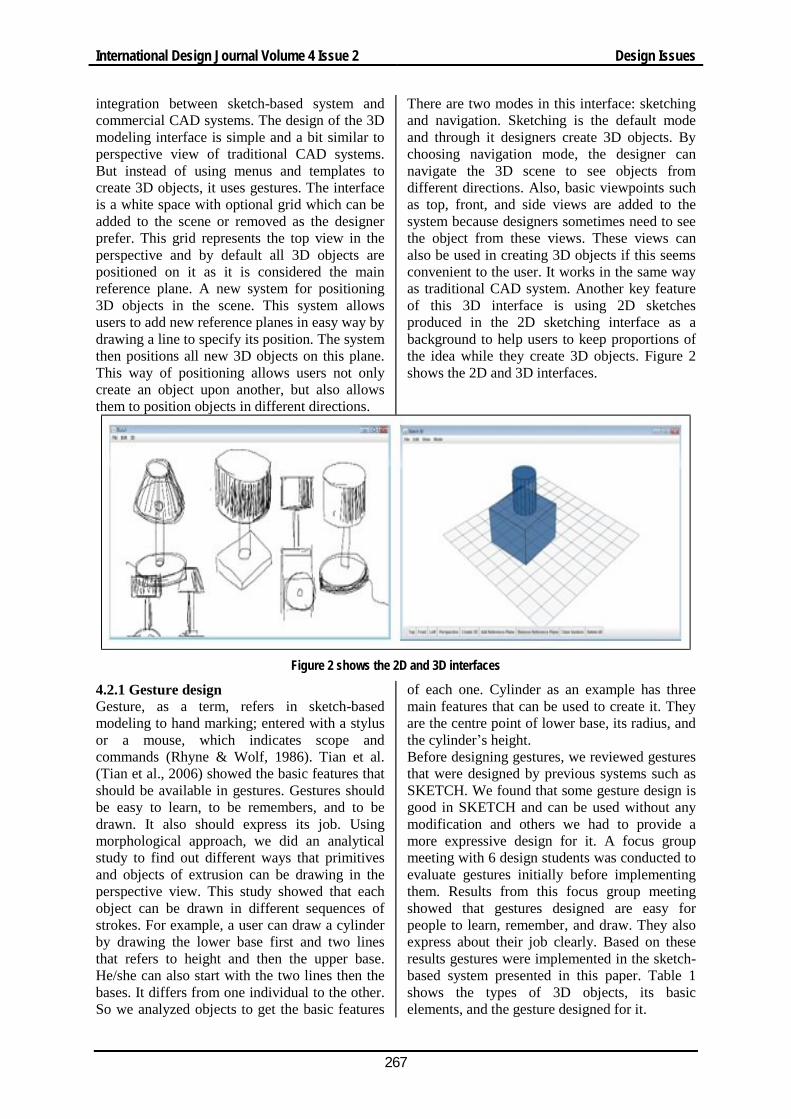
There are two modes in this interface: sketching and navigation. Sketching is the default mode and through it designers create 3D objects. By choosing navigation mode, the designer can navigate the 3D scene to see objects from different directions. Also, basic viewpoints such as top, front, and side views are added to the system because designers sometimes need to see the object from these views. These views can also be used in creating 3D objects if this seems convenient to the user. It works in the same way as traditional CAD system. Another key feature of this 3D interface is using 2D sketches produced in the 2D sketching interface as a background to help users to keep proportions of the idea while they create 3D objects. Figure 2 shows the 2D and 3D interfaces.
Figure 2 shows the 2D and 3D interfaces
4.2.1 Gesture design Gesture, as a term, refers in sketch-based modeling to hand marking; entered with a stylus or a mouse, which indicates scope and commands (Rhyne & Wolf, 1986). Tian et al. (Tian et al., 2006) showed the basic features that should be available in gestures. Gestures should be easy to learn, to be remembers, and to be drawn. It also should express its job. Using morphological approach, we did an analytical study to find out different ways that primitives and objects of extrusion can be drawing in the perspective view. This study showed that each object can be drawn in different sequences of strokes. For example, a user can draw a cylinder by drawing the lower base first and two lines that refers to height and then the upper base. He/she can also start with the two lines then the bases. It differs from one individual to the other. So we analyzed objects to get the basic features
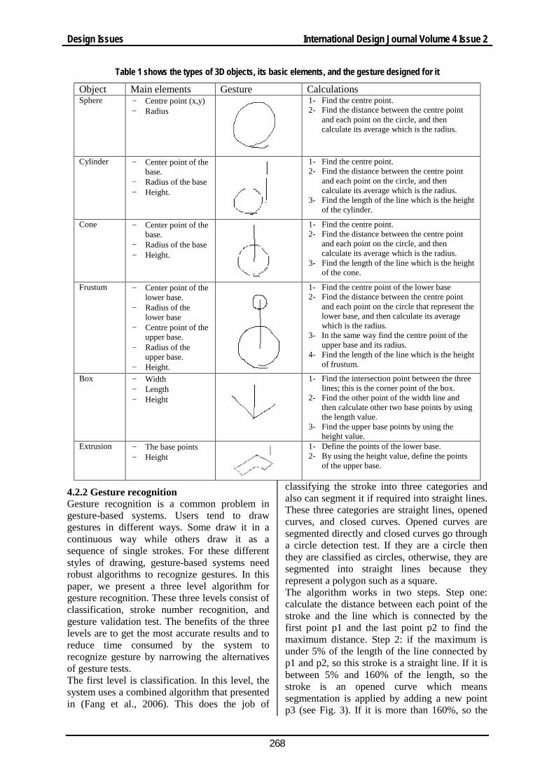
of each one. Cylinder as an example has three main features that can be used to create it. They are the centre point of lower base, its radius, and the cylinder’s height. Before designing gestures, we reviewed gestures that were designed by previous systems such as SKETCH. We found that some gesture design is good in SKETCH and can be used without any modification and others we had to provide a more expressive design for it. A focus group meeting with 6 design students was conducted to evaluate gestures initially before implementing them. Results from this focus group meeting showed that gestures designed are easy for people to learn, remember, and draw. They also express about their job clearly. Based on these results gestures were implemented in the sketch-based system presented in this paper. Table 1 shows the types of 3D objects, its basic elements, and the gesture designed for it.
International Design Journal Volume 4 Issue 2 Design Issues
268
Table 1 shows the types of 3D objects, its basic elements, and the gesture designed for it
Object Main elements Gesture Calculations Sphere − Centre point (x,y)
− Radius
1- Find the centre point. 2- Find the distance between the centre point
and each point on the circle, and then calculate its average which is the radius.
Cylinder − Center point of the base.
− Radius of the base − Height.
1- Find the centre point. 2- Find the distance between the centre point
and each point on the circle, and then calculate its average which is the radius.
3- Find the length of the line which is the height of the cylinder.
Cone − Center point of the base.
− Radius of the base − Height.
1- Find the centre point. 2- Find the distance between the centre point
and each point on the circle, and then calculate its average which is the radius.
3- Find the length of the line which is the height of the cone.
Frustum − Center point of the lower base.
− Radius of the lower base
− Centre point of the upper base.
− Radius of the upper base.
− Height.
1- Find the centre point of the lower base 2- Find the distance between the centre point
and each point on the circle that represent the lower base, and then calculate its average which is the radius.
3- In the same way find the centre point of the upper base and its radius.
4- Find the length of the line which is the height of frustum.
Box − Width − Length − Height
1- Find the intersection point between the three lines; this is the corner point of the box.
2- Find the other point of the width line and then calculate other two base points by using the length value.
3- Find the upper base points by using the height value.
Extrusion − The base points − Height
1- Define the points of the lower base. 2- By using the height value, define the points
of the upper base.
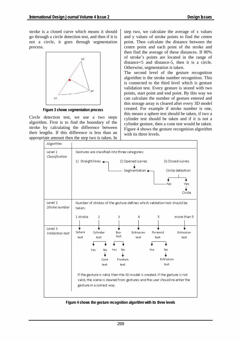
4.2.2 Gesture recognition Gesture recognition is a common problem in gesture-based systems. Users tend to draw gestures in different ways. Some draw it in a continuous way while others draw it as a sequence of single strokes. For these different styles of drawing, gesture-based systems need robust algorithms to recognize gestures. In this paper, we present a three level algorithm for gesture recognition. These three levels consist of classification, stroke number recognition, and gesture validation test. The benefits of the three levels are to get the most accurate results and to reduce time consumed by the system to recognize gesture by narrowing the alternatives of gesture tests. The first level is classification. In this level, the system uses a combined algorithm that presented in (Fang et al., 2006). This does the job of
classifying the stroke into three categories and also can segment it if required into straight lines. These three categories are straight lines, opened curves, and closed curves. Opened curves are segmented directly and closed curves go through a circle detection test. If they are a circle then they are classified as circles, otherwise, they are segmented into straight lines because they represent a polygon such as a square. The algorithm works in two steps. Step one: calculate the distance between each point of the stroke and the line which is connected by the first point p1 and the last point p2 to find the maximum distance. Step 2: if the maximum is under 5% of the length of the line connected by p1 and p2, so this stroke is a straight line. If it is between 5% and 160% of the length, so the stroke is an opened curve which means segmentation is applied by adding a new point p3 (see Fig. 3). If it is more than 160%, so the
Design Issues International Design Journal Volume 4 Issue 2
269
stroke is a closed curve which means it should go through a circle detection test, and then if it is not a circle, it goes through segmentation process.
Figure 3 shows segmentation process
Circle detection test, we use a two steps algorithm. First is to find the boundary of the stroke by calculating the difference between their lengths. If this difference is less than an appropriate amount then the step two is taken. In
step two, we calculate the average of x values and y values of stroke points to find the centre point. Then calculate the distance between the centre point and each point of the stroke and then find the average of these distances. If 80% of stroke’s points are located in the range of distance+5 and distance-5, then it is a circle. Otherwise, segmentation is taken. The second level of the gesture recognition algorithm is the stroke number recognition. This is connected to the third level which is gesture validation test. Every gesture is stored with two points, start point and end point. By this way we can calculate the number of gesture entered and this storage array is cleared after every 3D model created. For example if stroke number is one, this means a sphere test should be taken, if two a cylinder test should be taken and if it is not a cylinder gesture, then a cone test would be taken. Figure 4 shows the gesture recognition algorithm with its three levels.
Figure 4 shows the gesture recognition algorithm with its three levels
International Design Journal Volume 4 Issue 2 Design Issues
270
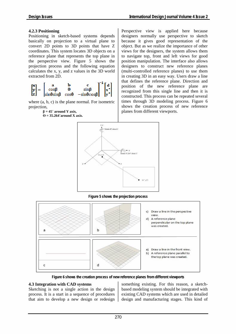
4.2.3 Positioning Positioning in sketch-based systems depends basically on projection to a virtual plane to convert 2D points to 3D points that have Z coordinates. This system locates 3D objects on a reference plane that represents the top plane in the perspective view. Figure 5 shows the projection process and the following equation calculates the x, y, and z values in the 3D world extracted from 2D.
where (a, b, c) is the plane normal. For isometric projection,
β = 45˚ around Y axis, Ө = 35.264˚around X axis.
Perspective view is applied here because designers normally use perspective to sketch because it gives good representation of the object. But as we realize the importance of other views for the designers, the system allows them to navigate top, front and left views for good position manipulation. The interface also allows designers to construct new reference planes (multi-controlled reference planes) to use them in creating 3D in an easy way. Users draw a line that defines the reference plane. Direction and position of the new reference plane are recognized from this single line and then it is constructed. This process can be repeated several times through 3D modeling process. Figure 6 shows the creation process of new reference planes from different viewports.
Figure 5 shows the projection process
Figure 6 shows the creation process of new reference planes from different viewports
4.3 Integration with CAD systems Sketching is not a single action in the design process. It is a start in a sequence of procedures that aim to develop a new design or redesign
something existing. For this reason, a sketch-based modeling system should be integrated with existing CAD systems which are used in detailed design and manufacturing stages. This kind of
Design Issues International Design Journal Volume 4 Issue 2
271
integration between sketch-based modeling and CAD systems can reduce time consumed in creating 3D models in the detailed design stage. If we can use 3D models produced by sketching, we will just need some simple modifications to have an accurate 3D models which are valid for manufacturing activities. In this interface an IGES file is produced to export data into commercial CAD systems to enable editing of 3D models produced by sketching. Producing of IGES file require a translator to translate 3D information into IGES entities. This translator works in 4 steps to translate each 3D object into its entities. In the first step, the translator creates the head of the IGES file that contains essential information about the file. In the second step, it finds the number of objects in the scene and classifies them. In the third step, the translator translates objects one by one into the file. In the last step, it creates the terminate part of the file.
5 Case studies We conducted two case studies before conducting a user study. The aim of these case studies is to examine specific features of the system. Each case study has a degree of complexion which is related to the features should be examined.
5.1 Case study 1 The aim of this case study is to examine some features that related to easiness of the sketching process. These features are: • The easiness and intuition of the 2D
sketching window. • Using sketches as a reference image in the
3D modeling. • The easiness of the 3D modeling process.
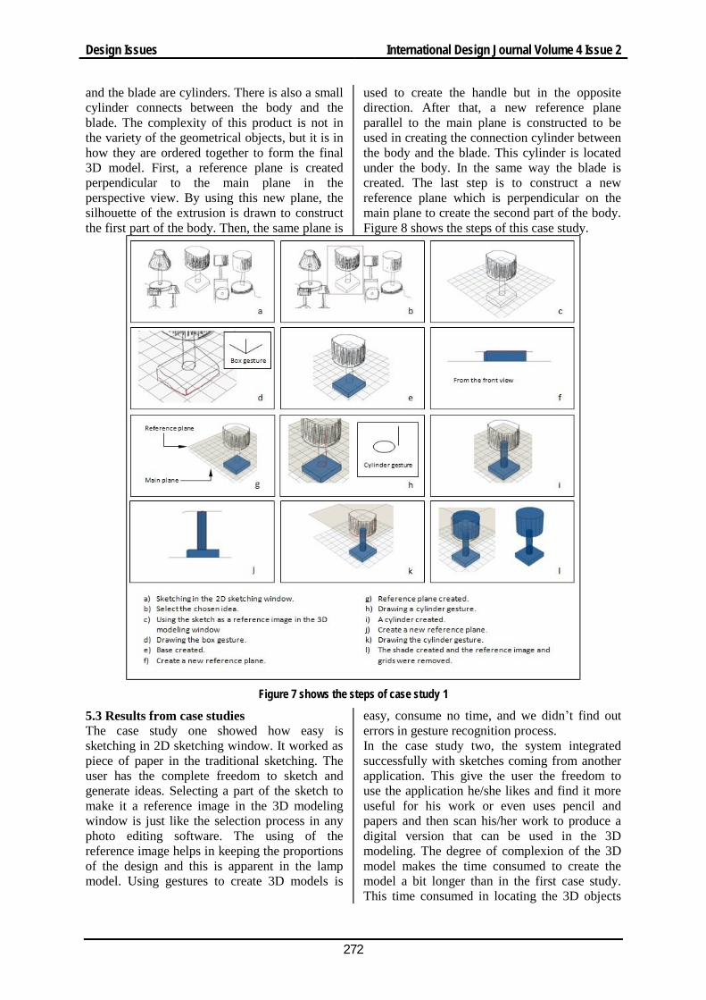
The examination of these features is based on generating some ideas by using the 2D sketching interface. One idea then is chosen to be transferred into the 3D modeling interface. This sketch transferred is used as a reference image in the background to help in keeping the proportions of the design while the user constructs the 3D models. In the 3D modeling interface, gestures are used to construct rough and quick 3D model of the idea. To do previous steps, a simple product was chosen to be sketched and modeled in this case study. This product is a lamp with a shade. This product is usually used in commercial CAD tutorials to teach users basic techniques. By using the 2D sketching interface, several ideas
were sketched by using tablet PC and a stylus. This sketch contains perspective and side view drawing in the same way the many designers sketch. After that, one idea was selected to be transferred into the 3D modeling. This idea was used as a reference image in the background in the 3D modeling interface. By using gestures, the 3D model of the lamp was constructed. This lamp is consisted of a box which represents its base, a cylinder which represents the column that carries the lamp and the shade, and another cylinder which represents the shade. First, by using the gesture of the box in the perspective view, a box was constructed. After that, in the front viewport, we draw a line to specify a parallel reference plane to use it in constructing the cylinder which represents the carrier of the shade. Back to the perspective viewport, a gesture of the cylinder was drawn and a cylinder was created. This step was repeated again to specify a new reference plane for the cylinder that represents the shade. Figure 7 shows the steps of this case study.
5.2 Case study 2 The aim of this case study is to examine the ability of the system to construct more complex 3D models. Building complex 3D models require easy positioning tool. Then, the easiness of the reference plane using may be examined in this case study too. Features which were examined in this case study are: • Integration between the system and other
2D sketching applications. • Creation of more complex 3D models. • The easiness of using reference planes.
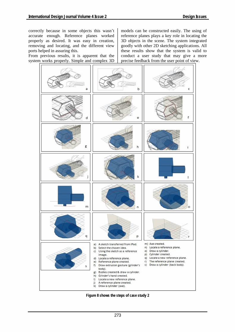
The examination of these features is based on using a 2D sketching application which developed for IPad to create a quick sketch of a complex product. Then use this sketch within the 3D modeling interface as a reference image to help in creating the 3D model. After that, gestures and reference planes were used to construct the 3D model of this complex product. In this case study, a grinder was chosen as a complex product. First, the Sketch application was used with an IPad device to draw a quick sketch of a grinder. This sketch was saved as a picture and transferred by using e-mail to the 3D modeling interface. In the 3D modeling interface, this image was used as a background. The grinder consists of the body, handle, and the blade. The body consists geometrically of an object of extrusion and a cylinder. The handle
International Design Journal Volume 4 Issue 2 Design Issues
272
and the blade are cylinders. There is also a small cylinder connects between the body and the blade. The complexity of this product is not in the variety of the geometrical objects, but it is in how they are ordered together to form the final 3D model. First, a reference plane is created perpendicular to the main plane in the perspective view. By using this new plane, the silhouette of the extrusion is drawn to construct the first part of the body. Then, the same plane is
used to create the handle but in the opposite direction. After that, a new reference plane parallel to the main plane is constructed to be used in creating the connection cylinder between the body and the blade. This cylinder is located under the body. In the same way the blade is created. The last step is to construct a new reference plane which is perpendicular on the main plane to create the second part of the body. Figure 8 shows the steps of this case study.
Figure 7 shows the steps of case study 1
5.3 Results from case studies The case study one showed how easy is sketching in 2D sketching window. It worked as piece of paper in the traditional sketching. The user has the complete freedom to sketch and generate ideas. Selecting a part of the sketch to make it a reference image in the 3D modeling window is just like the selection process in any photo editing software. The using of the reference image helps in keeping the proportions of the design and this is apparent in the lamp model. Using gestures to create 3D models is
easy, consume no time, and we didn’t find out errors in gesture recognition process. In the case study two, the system integrated successfully with sketches coming from another application. This give the user the freedom to use the application he/she likes and find it more useful for his work or even uses pencil and papers and then scan his/her work to produce a digital version that can be used in the 3D modeling. The degree of complexion of the 3D model makes the time consumed to create the model a bit longer than in the first case study. This time consumed in locating the 3D objects
Design Issues International Design Journal Volume 4 Issue 2
273
correctly because in some objects this wasn’t accurate enough. Reference planes worked properly as desired. It was easy in creation, removing and locating, and the different view ports helped in assuring this. From previous results, it is apparent that the system works properly. Simple and complex 3D
models can be constructed easily. The using of reference planes plays a key role in locating the 3D objects in the scene. The system integrated goodly with other 2D sketching applications. All these results show that the system is valid to conduct a user study that may give a more precise feedback from the user point of view.
Figure 8 shows the steps of case study 2
International Design Journal Volume 4 Issue 2 Design Issues
274
6 User study The aim of this user study is to evaluate the sketch-based system presented in this thesis. The scenario of this user study is to prepare the user to be familiar with the system first and then do some tasks. After that, he/she evaluates the system through answering a questionnaire. According to that, this user study is divided into two sections: a tutorial, and a questionnaire. Through the tutorial, the user can investigate and practice the system. In the questionnaire section, the user answers questions to evaluate gestures, idea generation process, and the 3D modeling.
6.1 Tutorial design The aim of this tutorial is to familiarize the user with system to be able to use it conveniently. And after that he can practice exercises shown in the tutorial easily. The tutorial is designed to be gradual in its contents. It is divided into four sections: navigation, idea generation process, 3D modeling process, and real practice experience. In the navigation section, the tutorial describes the contents of the 2D sketching and 3D modeling interfaces. It presents a general idea about how the system works. In the second section, it describes in details, how the 2D sketching interface works to produce ideas and draw sketches. It also shows how it integrates with other 2D sketching applications and with the 3D modeling interface. The 3D modeling section trains the user to construct simple and complex 3D models by using gestures. The last section aims to push the user to generate his own ideas and produce his sketches, and then convert them into 3D models.
6.2 Questionnaire study The questionnaire is divided into three parts: gesture evaluation, idea generation process, and 3D modeling process. Gesture evaluation part contains questions about how a gesture is easy to remember, to draw, and to learn and how it expresses about the job. Questions about idea generation process are about how the 2D sketching space enhances thinking and concentration on the idea generation and whether it allows user to explore the idea freely. The last part contains questions about the 3D modeling process and how it is easy to create and manipulate 3D objects.
6.3 Results from the user study 20 individuals participated in the user study, took the questionnaire and returned results. Participants are design students in Brunel
University, 14 male and 6 female. Research finding from the questionnaire study involved in the evaluation test are as follows: • Most respondents (over 90%) agreed that
gestures used to create 3D models were easy to remember and to draw.
• 84% of respondents found that gestures were easy to learn and 12% accepted that but thought it needing longer time to be familiar with it.
• More than 60% of participants strongly agreed that gestures expressed the job and others agreed that with a less degree.
• Respondents found the 2D sketching space that the system provided allowed users to sketch freely and enabled him/her to draw many ideas and saved sketches for further usage. 90% of them also considered it supported the quick flow of ideas, but this percentage reduced to 60% when they had been asked about if it gave the user the chance for more concentration on ideas and using hand-made sketches.
• For the 3D modeling interface, most of respondents agreed that creation of the 3D models was easy in contrast to CAD systems.
• 90% of them fairly agreed that they were able to place objects in the right place and different viewports and navigation mode that system provided were very helpful in that.
• Respondents strongly agreed that grid provided in the 3D interface gave them the feeling of the depth and using reference image in the background helped them to be aware of proportion through the 3D creation process.
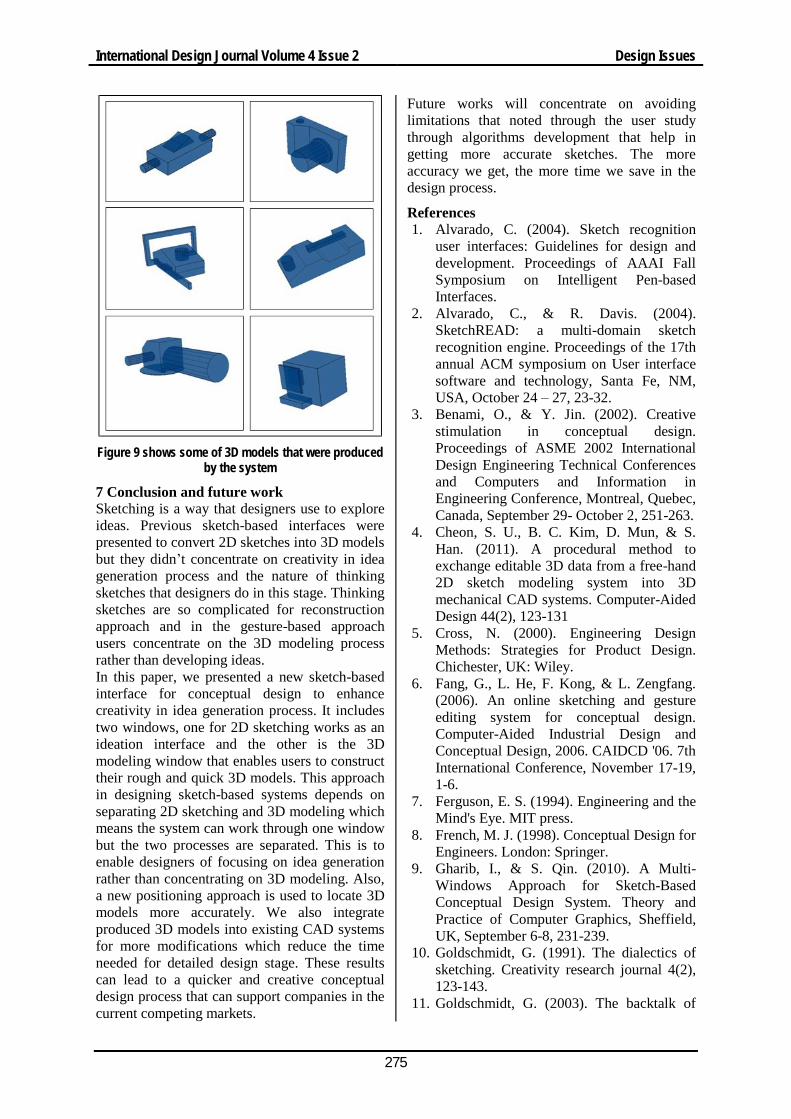
Some limitations were noted from comments about wrong positioning in some cases and some wrong gesture recognitions. The chance of wrong case happening was less than 7%, some were related to a system failure and others were due to the users’ unfamiliar with the system. Figure 9 shows some of 3D models that were produced by the system to show its different abilities.
Design Issues International Design Journal Volume 4 Issue 2
275
Figure 9 shows some of 3D models that were produced
by the system
7 Conclusion and future work Sketching is a way that designers use to explore ideas. Previous sketch-based interfaces were presented to convert 2D sketches into 3D models but they didn’t concentrate on creativity in idea generation process and the nature of thinking sketches that designers do in this stage. Thinking sketches are so complicated for reconstruction approach and in the gesture-based approach users concentrate on the 3D modeling process rather than developing ideas. In this paper, we presented a new sketch-based interface for conceptual design to enhance creativity in idea generation process. It includes two windows, one for 2D sketching works as an ideation interface and the other is the 3D modeling window that enables users to construct their rough and quick 3D models. This approach in designing sketch-based systems depends on separating 2D sketching and 3D modeling which means the system can work through one window but the two processes are separated. This is to enable designers of focusing on idea generation rather than concentrating on 3D modeling. Also, a new positioning approach is used to locate 3D models more accurately. We also integrate produced 3D models into existing CAD systems for more modifications which reduce the time needed for detailed design stage. These results can lead to a quicker and creative conceptual design process that can support companies in the current competing markets.
Future works will concentrate on avoiding limitations that noted through the user study through algorithms development that help in getting more accurate sketches. The more accuracy we get, the more time we save in the design process.
References 1. Alvarado, C. (2004). Sketch recognition
user interfaces: Guidelines for design and development. Proceedings of AAAI Fall Symposium on Intelligent Pen-based Interfaces.
2. Alvarado, C., & R. Davis. (2004). SketchREAD: a multi-domain sketch recognition engine. Proceedings of the 17th annual ACM symposium on User interface software and technology, Santa Fe, NM, USA, October 24 – 27, 23-32.
3. Benami, O., & Y. Jin. (2002). Creative stimulation in conceptual design. Proceedings of ASME 2002 International Design Engineering Technical Conferences and Computers and Information in Engineering Conference, Montreal, Quebec, Canada, September 29- October 2, 251-263.
4. Cheon, S. U., B. C. Kim, D. Mun, & S. Han. (2011). A procedural method to exchange editable 3D data from a free-hand 2D sketch modeling system into 3D mechanical CAD systems. Computer-Aided Design 44(2), 123-131
5. Cross, N. (2000). Engineering Design Methods: Strategies for Product Design. Chichester, UK: Wiley.
6. Fang, G., L. He, F. Kong, & L. Zengfang. (2006). An online sketching and gesture editing system for conceptual design. Computer-Aided Industrial Design and Conceptual Design, 2006. CAIDCD '06. 7th International Conference, November 17-19, 1-6.
7. Ferguson, E. S. (1994). Engineering and the Mind's Eye. MIT press.
8. French, M. J. (1998). Conceptual Design for Engineers. London: Springer.
9. Gharib, I., & S. Qin. (2010). A Multi-Windows Approach for Sketch-Based Conceptual Design System. Theory and Practice of Computer Graphics, Sheffield, UK, September 6-8, 231-239.
10. Goldschmidt, G. (1991). The dialectics of sketching. Creativity research journal 4(2), 123-143.
11. Goldschmidt, G. (2003). The backtalk of
International Design Journal Volume 4 Issue 2 Design Issues
276
self-generated sketches. Design Issues 19(1), 72-88.
12. Gonen, O., & E. Akleman. (2012). Sketch based 3D modeling with curvature classification. Computers & Graphics 31(5), 521-525.
13. Igarashi, T., & J. F. Hughes. (2001). A suggestive interface for 3D drawing. The 14th Annual ACM Symposium on User Interface Software and Technology, Orlando, Florida, November 11-14, 173-181.
14. Igarashi, T., S. Matsuoka, & H. Tanaka. (1999). Teddy: a sketching interface for 3D freeform design. Proceedings of the 26th annual conference on Computer graphics and interactive techniques, 409-416.
15. Jansson, D. G., & S. M. Smith. (1991). Design fixation. Design Studies 12(1), 3-11.
16. Jin, Y., & P. Chusilp. (2006). Study of mental iteration in different design situations. Design studies 27(1), 25-55.
17. Karpenko, O., J. F. Hughes, & R. Raskar. (2002). Free‐form sketching with variational implicit surfaces. Computer Graphics Forum 21(3), 585-594.
18. Kruger, C., & N. Cross. (2001). Modeling cognitive strategies in creative design. Computational and cognitive models of creative design, University of Sidney, Australia.
19. Lim, S., S. F. Qin, P. Prieto, D. Wright, & J. Shackleton. (2004). A study of sketching behaviour to support free-form surface modelling from on-line sketching. Design studies 25(4), 393-413.
20. Maher, M. L., J. Poon, & S. Boulanger. (1996). Formalizing design exploration as co-evolution. Advances in Formal Design Methods for CAD, 3-30.
21. Mao, C., S. F. Qin, & D. Wright. (2009). A sketch-based approach to human body modelling. Computers & Graphics 33(4), 521-541.
22. Masry, M., & H. Lipson. (2007). A sketch-based interface for iterative design and analysis of 3d objects. ACM SIGGRAPH
2007 courses. 23. Rhyne, J. R., & C. G. Wolf. (1986).
Gestural interfaces for information processing applications. International Business Machines Incorporated, Thomas J. Watson Research Center.
24. Rubine, D. (1991). Specifying gestures by example. Computer Graphics 25(4), 329-337.
25. Schmidt, R., B. Wyvill, M. C. Sousa, & J. A. Jorge. (2006). Shapeshop: Sketch-based solid modeling with blobtrees. ACM SIGGRAPH 2006 Courses.
26. Schon, D. A., & V. DeSanctis. (1986). The reflective practitioner: How professionals think in action. The Journal of Continuing Higher Education 34(3), 29-30.
27. Scrivener, S. A., L. J. Ball, & W. Tseng. (2000). Uncertainty and sketching behaviour. Design Studies 21(5), 465-481.
28. Sutherland, I. E. (1964). Sketch pad a man-machine graphical communication system. Proceedings-Spring Joint Computer Conference, 329-346.
29. Tian, F., T. Cheng, H. Wang, & G. Dai. (2006). Research on user-centered design and recognition pen gestures. Advances in Computer Graphics, 312-323.
30. Wenpeng, X., & Q. Xiaohuang. (2010). Sketch-Based Parameterized Garment Modeling. In Information and Computing (ICIC), 2010 Third International Conference 3, 248-251.
31. Wyche, S. P., & R. E. Grinter. (2012). Using sketching to support design research in new ways: a case study investigating design and charismatic pentecostalism in São Paulo, Brazil. Proceedings of the 2012 iConference, 63-71.
32. Yang, M. C. (2009). Observations on concept generation and sketching in engineering design. Research in Engineering Design 20(1), 1-11.
33. Zeleznik, R. C., K. P. Herndon, & J. F. Hughes. (1996). SKETCH: an interface for sketching 3D scenes. Proceedings of SIGGRAPH’96, 163-170.