design of information systems using scenario-driven techniques · 1. introduction...
TRANSCRIPT
j:r Reference pifbl-
Aiiios
NBSIH b1-2240
Design of Information SystemsUsing Scenario-Driven Techniques^lla<n^ll iiiiriTfiiM w wi
'
n i~ tm» \ ifiim iBim 'ii iTrni r iTrMniiwi i iii n iwi ii i iiiiTfwnnwrin n rr miMiTFi~wMraBmwiM»iM~mgwrwiir<MW¥trnmwniiTTniirTTBMTiMMiiTrT»wwri« irarM t
W. T. Hardgrave
S. B. Salazar
E. J. Seller, III
Data Management and
Programming Languages Division
Center for Programming Science and Technology
Institute for Computer Sciences and Technology
U.S. Department of CommerceNational Bureau of Standards
Washington, DC 20234
^/arch 1S81
100
. U56 EPARTMENT OP CCMMSPCc


VAVIOMAL UBBAUcnr standawm
UBtABT
MAY 1 8 1981
NBSIR 81-2240_ >0
DESIGN OF INFORMATION SYSTEMS'
^
USING SCENARIO-DRIVEN TECHNIQUES l
W. T, Hardgrave
S. B. Salazar
E. J. Belief, III
Data Management and
Programming Languages Division
Center for Programming Science and Technology
Institute for Computer Sciences and Technology
U.S. Department of CommerceNational Bureau of Standards
Washington, DC 20234
March 1 981
U.S. DEPARTMENT OF COMMERCE, Malcolm Baldrige, Secretary
NATIONAL BUREAU OF STANDARDS, Ernest Ambler, Director

s.
-r-
-i4sau« ^J4t(OtTA« - w
•fMAOMAT* «0 „TIAIKUl
/:
M:.'^
t
reef 8 ,i yaw..3i
*v
rir?
'
r d* .,. -4 '
D^Si- f‘8
sM^trevg MOKTANmo^ ifloiaao
.iti
.
I<i.>’ ifT'\ ';'«*. '.51
f'Ti
w:*'. :
.-Si'?
"^f c
I.
»y*>QbS^' tvw
.'3i.A>';
Hi'«'
‘>.
' *
. V'" •
w
T.. T-tB!1r'^' '*
. H'*
Rt,6<}
‘'#^1 "WW/*; %» " •* - ,' - - -7. - - -
I>.'
. MMm, ]:. '.:,T'^ ' '
iJd'l'nU*
hdAj..^i
rr,4H
%
•mm Jli''
..'A :k‘'
_jj;r iBfc f
;' A-:
„•>
, ...
' '*•. ®
.V - V n- t
..i/W .
'*''SL
,i*BaM¥ce’»o;’tMaMTJrA*!sa‘c»;^ •>
io|9«f^C^%,WrrvA,'j^ 5^:0: »iA3fRji0 JAH®t.Ak1--#%' ; .ija’
3

Design of Information SystemsUsing Scenario-Driven Techniques
W. Terry HardgraveSandra B. Salazar
Edwin J. Beller III
6 January 1981
National Bureau of StandardsInstitute for Computer Sciences and Technology
Washington, D.C.
This paper describes a technique for develop-ing information systems using a scenario-drivendesign approach. The approach emphasizes client(that is, the user who is purchasing the system)participation in the design process. The firststep is to develop a collection of "scenarios"which document the interaction between the comput-er and the human user. Using the scenarios,information-flow diagrams and database designs maybe constructed. After the client has approvedthese documents, they can be used to establishdisk capacity requirements and transaction rates,and finally to specify all hardware and softwarerequirements. The primary advantage of this ap-proach is that the scenarios provide a good indi-cation of the ultimate usefulness and cost of thesystem. The client can review these documents andapprove, modify, or reject the system design be-fore any software is generated. This paperdescribes the scenarios, the information flowtechnique, and the database design approach using,as an example, a small business application.

if-
m
cvaijmnis4^ to tt^ mmap^Jkwt2
#V« *
/B ijbrtfiifc ':])s
Itl * ft'iWbH
^
J0^ J Y30mA^^wmoi
1 *;
4r‘Ypolonrfa^T TOl
%\‘
-<?olfve& ^o3f fi eBcU^ti^^b' 1 m f ' • "
. w ji» —
^XT«jtio ff<ss43lKi<o*R© dnT «‘ '
'
f ffVMs.
4
jeA.\f n. w 1 - '7'
: ^r- o»., 1 «rf9#OTqq»
,9ir(T .#fe»,t»cT(^. £s-^ii^.f^^" tt^9. ai
,»(yi!ii!i;0^pfc rt^rnm 4rtJ h» 5 «i
"*'
Yirm effteiit-i.
id o/ 6c/JmJ. '^‘S- . ,‘H’ -k. . avib ^£k f'o3 ', Bbsfj :' 4^' jsj>!irr '\^ 0 e 9a^ ^
bwi^a<SiRP>ltr^t' X«i6 i«Tf iSV^taoa? brtTS »d / 4 1? yS^i159^ , oi? yil i*ni 1 60a ^ ^
-cA 3-<?AirtAvJtc ,Y^A<(fi,,'t'q, ''l^$;r^^ '4Bin;A>.JteAiiq|>ea-ifcfri. Bofep 6^,e&ivOT% ffr>A07q
5o j'
4oc3 „ 04'e^a,Mu. ««J ' ip ^mi^BoiiOB wBn^vwoob ‘
jfe Ae^-f " t v^'.. imp'' i^fUi&. ^ifff' /ftf«.5»vi"Sd ap4»©,ft «is:J py« "<»vpVq4»3«^q a 1 4JT » Jopj.a 3 s^'aa
,.
. d'l'
'
4''*''3*ip.a.
y/t-a*. !»Kji'iwoXi oo4^Afjr^a/i|'.p«i 0 <i dPAb'fqpA frplWfc P044fo'4 ,!&.' ,P^'p^<k;frS'
^9^^ eeeniAtfcf J' 4‘^A'9^A;' ta'iqau^e (ia
.r.9!
''.“ '*•.
,i’- 'd ./ I,. «„.*.• <;
^

TABLE OF CONTENTS
Page
1. Introduction 2
2. Scenarios 4
2.1 Definition 4
2.2 Development 4
2.3 Menu Format 5
2.4 Sample Screens and Menus 6
3. Flow Diagrams 10
3.1 Characteristics 10
3.2 Sample Flow Diagram 11
4. Data-base Design 14
4.1 Entities 14
4.2 Relationships 15
4.3 Data Dictionary 18
5. Concluding Remarks 20
6. References 20

1 . Introduction
Designing an interactive information system requiresspecialized techniques that are unnecessary in the develop-ment of other types of computer systems. Human factors is-sues are involved, since the user community typically doesnot consist of computer specialists. Interactions betweenhumans and computers must be clearly defined. The databasemust be described independently of any particular programs.Standard flowchart practices must be modified to capture thedata flow through an interactive system.
This paper describes a technique for developing a logi-cal design for an interactive information system. The pro-duct of this design process is a document having these com-ponents :
* Collection of scenarios
* Information flow diagrams
* Data-base design
Step-by-step approaches to the development of the com-ponents, which are identified below, will be presented insubsequent sections.
The term "scenario" is defined for the purpose of thispaper as a detailed documentation of the interaction betweena computer system and the human user working at a terminal.\ scenario is essentially a hard-copy of an interactive ses-sion. This level of detail is seldom available until afterthe system is implemented and capable of writing output to aterminal. One goal of the scenario-driven design approach isto capture this level of detail before implementation.
The collection of scenarios is a complete descriptionof every screen format that the terminal operator may possi-bly encounter. The data appearing in the scenarios shouldbe typical of data that may actually be used in the applica-tion. Thus, this collection of scenarios completely and "byexample" describes the user interface to the informationsystem. The scenarios are discussed further in Section 2.
The information flow diagrams describe the movement ofdata through the system. They show where data enters thesystem, where it exits, where it is stored, and where it isdisplayed for the human user. While standard flowchartshave had widespread usage, the application of flow diagramsto interactive systems requires a somewhat different
- 2 -

approach. A particular format and some stringent conven-tions are discussed in Section 3.
The database design is a complete description of thedata that is to be held and permanently maintained by thesystem. One expects this data to have a long life span;certainly it will be longer than the execution time of anyprograms that manipulate it. Therefore, it is necessary todescribe the data apart from any particular program orsubroutine. The database design technique, discussed in sec-tion 4, is an application and extension of the "entity-relationship model" CCHEN76].
The scenario-driven technique is currently beingdesigned as part of a project to automate the operation of awholesale book dealer. The examples used throughout thispaper are taken from that application.
There is one significant advantage of this method.There will be detailed communication between the systemdesigner and the client (the user who has contracted to pur-chase the system) during the design stage, as the clientwill review the scenarios many times during their develop-ment. Thus, when the report on the logical design is avail-able, the client is already familiar with the system and canbe confident that it meets expected needs. There is no mys-tery and little chance that the client will receive a systemsubstantially different than envisioned.
- 3 -

2 . Scenarios
2.1 Definition
A scenario is a detailed documentation of the interac-tion between a computer system and the human user working ata terminal. Scenarios may be written to mimic the interac-tion on a line-by-line basis; a menu-by-menu basis, ascreen-by-screen basis, or any other basis that can reason-ably be put into the design document. For the bookwholesaler system, scenarios are written on a screen-by-screen basis, that is, each complete computer-human interac-tion (such as "ordering", "receiving") is documented interms of the screens sequentially viewed by the user. Eachscreen described here consists of a menu or a menu plus sys-tem prompts.
Most importantly, the scenario is a tool to facilitatecommunication between the client and the system designer.That is, the scenario is a very simple visual image thatdescribes one part of system behavior. A comprehensive col-lection of scenarios can describe system behavior in enoughdetail to convince the client that the system will performas envisioned.
There are some other benefits that come with thedevelopment of detailed scenarios:
* The scenarios may be included in the User's Manualas tutorial material.
* The scenarios may be incorporated into a test planto determine system acceptance.
* The scenarios may be used as the basis for the con-tract between the client and the systems designer orsoftware implementer.
The following subsections will discuss the developmentof screen-based scenarios and the menu format. Examples ofmenus from the wholesale book system are included.
2.2 Development
In a screen-based scenario design, all scenarios willhave in common the top level screen, that is, the firstscreen that the user views. The master menu gives an over-view of the aspects of the organization addressed by the
_4_

information system, thereby defining the scope of the sys-tem. The designer and the client must work on the mastermenu until an agreement is reached and the menu satisfiesboth parties. During this process, the system designer andthe client must learn each other's terminology and develop a
common basis for further work.
After some agreement is reached on the nature of themaster menu, work may proceed on the screens at the nextlevel of detail. There is no established format for thescenarios; the screens may describe menus, user commands, orany interaction that is acceptable to both the client andthe designer. This process of defining progressively lowerlevels of the system continues until all possible interac-tions have been completely specified.
There are problems involved in the management of thisdocumentation. An exhaustive enumeration of all possiblescenarios will result in a large number of screens for evena small system. As menus at different levels areredesigned, it becomes tedious to maintain consistency andverify correctness of the interfaces.
The notation used in the scenarios is not ametalanguage. The data requested from the user or printedfor the user should be typical data from actual situations.This avoids any formatting problems and similar misunder-standings between the client and the systems designer.
2.3 Menu Format
The menu format is illustrated in Figures 2-1 through2-4. Each menu (and its corresponding screen) is numberedto indicate its level, starting with the master menu as 0.0.A menu has four columns with the following headings;
* Mumber
* Option
* Next
* Page
Each entry in the menu represents a possible selectionby the user. The "option" is the textual statement of thefunction that is displayed for the terminal operator. The"num.ber" signifies the key stroke to select the correspond-ing option.
- 5 -

The "next" and "page" fields do not actually appear onthe screen when the system is implemented. However, theyare necessary for the writer and the reader of the logicaldesign document in order to develop and follow the sequenceof menu displays. The "next" field indicates which menu ap-pears next if the corresponding number is selected. The"page" field gives the actual page number in the logicaldesign document. Both of these fields are useful, albeitredundant. The page field is useful to the reader of the fi-nal design document; and the next field is useful during thedevelopment cycle, when menu numbers are available but pagenumbers are not.
2.4 Sample Screens and Menus
The sample screens on the following pages describe partof the "ordering" process for the book wholesaler system.The level 0.0 menu is the first menu that a terminal userwould see after starting the system. "Ordering" is selectedt>y typing "1" in response to the system's prompt "Selectone :
"
.
The "Next" field of the "ordering" entry indicates thatthe next menii to appear will be the 1.0 menu. After it ap-pears, as shown in Figure 2-2, the terminal user may chooseto order for a customer or order something to be stored inthe inventory. In this case, a "1" is typed to signify anorder for a customer.
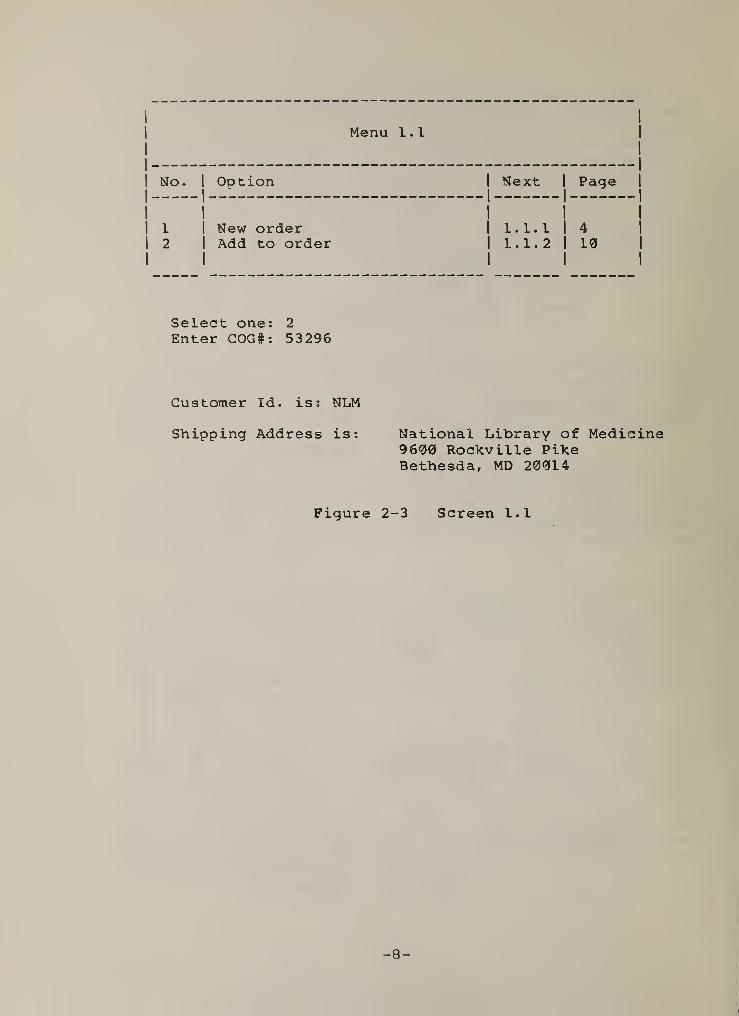
As indicated by the "Next" field of the first entry inthe 1.0 menu, the next menu to appear will be the 1.1 menu.In menu 1.1, the terminal user may choose to create a neworder or to add to an existing order. In this case, theuser chooses to add to an existing order by selecting "2".
The system then prompts the terminal user for the "CustomerOrder Group Number", abbreviated COG#. The system printsthe customer identifier and the shipping address.
According to the menu of the next screen, the 1.1.2menu, the terminal user may select to search for the titlebased on one of several possible inputs. In this case, theterminal user selects a search on ISBN. The system promptsfor the ISBN, the International Standard Book Number, whichis the unique identifier for books. After the ISBN has beenentered, the system adds the book to the order group andprints a message to that effect as shown. As indicated, thescreen would refresh itself to allow the operator to orderanother title for this customer order.
-6 -

Menu 0.0
No. 1 Option1
1 Next1
1 Page1
1
1
1 Ordering
1
- —— —— -
1
1 1.01
1 2
2 1 Receiving 1 2.0 1 403 1 Inquiry/Update 1 3.0 1 1064 1 Picking List/invoice/PO 1 4.0 1 1475 1 Accounting functions 1 5.0 1 1666 1 End of day 1 6.0 1 1837 1 Return to Operating System
1 1 1
Select one: 1
Figure 2-1 Screen 0.0
Menu 1 .
0
No. 1
- !
Option 1
. _ _ 1
.
Next 1 Page1
1
1
1 Order for customer1
1 1.11
1 3
2 1
1
Order for inventory 1
1
1.2 1 261
Select one: 1
Figure 2-2 Screen 1.0
- 7 -
Menu 1.1
No
.
1
- 1
Option 1 Next- - 1
1
-
1
Page
1
1
1 New order1
1 1.1.11
1 42 1
1
Add to order 1 1.1.21
1
1
10
Select one: 2
Enter COG#; 53296
Customer Id. is; MLM
Shipping Address is; National Library of Medicine9600 Rockville PikeBethesda, MD 20014
Figure 2-3 Screen 1.1
-8 -

Menu 1.1.2
No. 1 Option1
-
1 Next1
1
-
1
Page
1
1
1 Search on alt. key
—1
1
1 1.1. 2.1
1
1
! 302 1 Search on ISBN 1 1.1.2 1 103 1 Search on series 1 1.1. 2.
3
1 354 1 Enter as new title 1 1.1. 2.4 1 375 1 End order
1
1 0.01
1
1
1
Select one: 2
Enter ISBN: 0-13-854547
An order for Structured System Design by Gane and Sarsonhas been added to COG# 53296 for National Library of Medi-cine .
Figure 2-4 Screen 1.1.2
-9 -

3. Flow Diagrams
3.1 Characteristics
Flow charts have been used for many years to describethe flow of computer programs and data. Although the di-agrams used here are similar to traditional flow charts,some stringent rules for their creation and use have beenimposed. These restrictions, discussed below, make the di-agrams easier to read and more useful as a management tool.
As depicted in Figure 3-1, the format for the flow di-agram exhibits the following characteristics:
* All flow is from left to right.
* The triggering event is the first box on the left.
* The process ends with the rightmost box (usually la-beled "end").
* The left margin is partitioned by "roles"; that is,the organizational (or external) entities are listeddown the left margin. One role that is usually in-cluded is "database". In this way, processes thatstore data in or retrieve data from the database maybe documented.
* The boxes have various shapes that are assignedmeanings to fit the application. This example usestrapezoidal, square, and cylindrical symbols; themeanings are explained below.
The diagram shown in Figure 3-1 is short and fits onone page; most diagrams will require several pages.
There are several advantages in using this kind of flowdiagram:
* The triggering events can easily be spotted by look-ing on the leftmost part of the diagrams.
* The involvement of a particular role can be isolatedby looking along the appropriate horizontal strip.
* Time may be measured horizontally. Time intervalsafter triggering can be set up along the horizontalaxis and charting symbols placed in the appropriatezones
.
ig-

* Parallel charts may also be created. For example,in a manufacturing environment, a materials flow di-agram can be set up parallel to the information flowdiagram. The materials flow documents the flow ofparts, subassemblies, etc.; the information flow do-cuments the paperwork.
However, since a flow diagram should be generated foreach possible flow sequence, there may be problems with themanagement of this volume of documentation.
3.2 Sample Flow Diagram
The sample flow diagram shown in Figure 3-1 depicts theflow for the part of the ordering process discussed previ-ously. The trapezoidal boxes represent the display of amenu; the menu number is given inside the box. In caseswhere there is a square box underneath the trapezoid, themenu interaction requires input of a data-item by the termi-nal user. The name of the data-item is contained in thebox. The freestanding square boxes represent processes thatthe system performs. If the process stores or retrievesdata from the databases, this is signified by a line fromthe process to the appropriate database. Herein, the term"database" is used very loosely and could, in this case beused interchangeably with the term "file". The various da-tabases are represented by the cylindrical symbols.
In Figure 3-1, the flow begins on the left when thecustomer prepares the order. The order then goes to theordering department. The terminal operator calls the systeminto operation and the level 0.0 menu is displayed. This issignified by the trapezoid containing 0.0. The terminaloperator selects option 1; this is signified by the "1"
above the trapezoid. Then menu 1.0 is displayed. The ter-minal operator selects option 1; again this is signified bythe "1" above the trapezoid. Then menu 1.1 is displayed;the terminal operator selects option 2. The box below thetrapezoid indicates that the terminal operator must enterthe "Customer Order Group Number", abbreviated COG#. Asshown by the square box, the system retrieves the customerorder group from the "Customer Order File", abbreviated CO.Also, the system gets the "Customer Identifier", abbreviatedC#, from information contained in the COG. Finally, thesystem retrieves the "Shipping Address", abbreviated SA anddisplays it along with the customer number.
- 11 -

Tha next menu to be displayed is menu 1.1.2. The ter-minal operator chooses to search on ISBN. The system re-quests the ISBN and the operator enters it. The system thensearches the title file to ensure that the ISBN is valid.If the ISBN is not valid, then other menus not shown hereare invoked. Finally, the title is added to the COG and theprocess ends.
12 -

roles
I
PROCESS:
I
ADD-TO-ORDER
FIGURE
3'1:
SAMPLE
FLOW
DIAGRAM

4. Data-base Design
The database design is, roughly speaking, the format ofthe various data files that are to be stored permanently(usually on a disk). The actual values in the files maychange as different data enters and leaves the system. Wewill refine this concept as we proceed.
Our approach to database design consists of severalsteps as described below. While it is similar to theentity-relationship approach described by Chen [CHEN76], thetechnique is specified in more detail and may differ some-what from his philosophy.
The process consists of:
* Enumerating entities
* Determining the key attribute of each entity
* Defining non-key attributes for each entity
* Enumerating relationships
* Determining keys for the relationships
* Defining non-key attributes for the relationships
* Determining which relationships may also have thedual role of entities
* Assigning dual keys to dual entity/relationships
4.1 Entities
First, the designer must enumerate the entities. Anentity is a concept that the designer wants the informationsystem to recognize and manipulate. For example, in an in-ventory system, a part would be an entity. For some applica-tions, there are many possible choices for entities and de-cisions on tradeoffs may be required. The discussion hereinwill center on the Wholesale Books example rather than deal-ing with generalities.
In the wholesale book application, the basic entitiesare
:
- 14 -

* Customers
* Publishers
* Titles
Sample record diagrams giving the most important attri-butes of each entity are shown in Figure 4-1. In the actualdatabase, more attributes are necessary; some are omittedfor this discussion to keep it manageable.
Each entity is uniquely identifiable by a single attri-bute called the key (denoted by in the figures). Forexample, a person may be uniquely identifiable by his/hersocial security number or a part may be uniquely identifi-able by the part number.
4.2 Relationships
Next, the designer must enumerate the relationships,that is, the associations among entities. The attributes ofa relationship should describe the relationship, not the in-dividual entities, and therefore must include the keys, butno other attributes, of the entities involved.
Figure 4-2 shows some typical relationships; againthese are modified from the actual application for simplici-ty. However, they are quite similar to an early design be-fore the complexity required by the client was introduced.The item-order relationship relates customers to titles. Acustomer (CID) orders a title (ISBN) in some quantity (QTY)
.
The title/publisher relationship relates titles to publish-ers. A publisher (PID) publishes a title (ISBN).
Our example is somewhat more complex. The item-orderrelationship needs to be grouped to reflect which books ap-pear on an incoming order. Also, the item orders need to begrouped to reflect which items are included on a single ord-er to the publisher. Therefore, the item-order relationshipneeds to be referenced as an entity in other relationships.This is accomplished by adding an attribute. Customer OrderGroup (COG#) which becomes the key of the augmented item-order dual entity/relationship (as shown in Figure 4-3, withthe key denoted by "**").
-15

TITLES
ISBN* 1 Title 1 Author I Cost 1 Price
CUSTOMER 1
1
CID*^
1
1 C-Name 1 C-Address I
PUBLISHER
I PID* 1 P-Name 1 P-Address
Figure 4-1 Entities

I ITEM-ORDERSI
I CID* 1 ISBN* 1 Qty
title/publisher
ISBN* 1 PID*
Figure 4-2 Relationships
I ITEM-ORDERS1
1 COG#** 1 CID* 1 ISBN* ! QTY
Figure 4-3 Dual Entity/Relationship
- 17 -
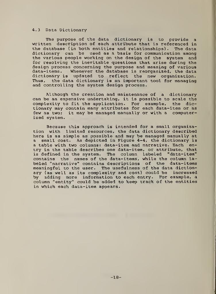
4.3 Data Dictionary
The purpose of the data dictionary is to provide awritten description of each attribute that is referenced inthe database (in both entities and relationships). The datadictionary can be used as a basis for communication amongthe various people working on the design of the system andfor resolving the inevitable questions that arise during thedesign process concerning the purpose and meaning of variousdata-items. Whenever the database is reorganized, the datadictionary is updated to reflect the new organization.Thus, the data dictionary is an important tool for managingand controlling the system design process.
Although the creation and maintenance of a dictionarycan be an expensive undertaking, it is possible to scale thecomplexity to fit the application. For example, the dic-tionary may contain many attributes for each data-item or asfew as two; it may be managed manually or with a computer-ized system.
Because this approach is intended for a small organiza-tion with limited resources, the data dictionary describedhere is as simple as possible and may be managed manually ata small cost. As depicted in Figure 4-4, the dictionary isa table with two columns: data-item and narrative. Each en-try in the table describes one data-item, or attribute, thatis defined in the system. The column labeled "data-item"contains the names of the data-items, while the column la-beled "narrative" contains descriptions of the data-itemsmeaningful to the user. The usefulness of the data diction-ary (as well as its complexity and cost) could be increasedby adding more information to each entry. For example, a
column "entity" could be added to keep track of the entitiesin which each data-item appears.
I
)
r
- 18-

1 DATA DICTIONARY I
i DATA-ITEM ! NARRATIVE-
i- - -
1 ISBN 1 International Standard Book Number1 Title 1 Title of book1 Author 1 Author of book1 Cost 1 Publisher's price of book1 Price 1 Our normal price for this book1 CID 1 Unique identifier for customer1 C-Name 1 Name of Customer1 C-Address 1 Address of Customer1 PID 1 Unique identifier for Publisher1 P-Name 1 Name of Publisher1 P-Address 1 Address of Publisher1 Qty 1 Quantity; Number of this ISBN
1 ordered by this CID1 COG# 1 Customer Order Group Number: Unique
1 identifier for Purchase Order
Figure 4-4 Data Dictionary Table
- 19-

5. Concluding Remarks
The information system design technique presented inthis paper is based on a surprisingly simple but rarely-usedidea— that the systems analyst build a mock-up of the sys-tem for review by the client before implementation begins.The method of constructing the mock-up, described herein, isthe development of a collection of "scenarios," the possibleinteractions between the computerized information system andthe human user. The client and the system designer takepart in a number of iterations of reviewing and revising thescenarios, while the information flow and the databasedesign proceed in parallel. Approval of a collection ofscenarios by the client is the first milestone in thedevelopment of the system.
6. References
CHEN76 Chen, Peter, "The Entity-Relationship Model — To-ward a Unified View of Data", ACM Transactions onDatabase Systems, Vol. 1, No. 1, March 1^76, pp.
GANE79 Gane, Chris and Sarson, Trish, Structured SystemsAnalysis ; Tools and Techniques Prentice-Hall, En-glewood Cliffs, NJ, 1979, 241 p.
- 20 -

U.S. DEPT. OF COMM. 1. PUBLICATION OR 2. Performing Organ„ Report No,^ 3. Pl''.
|
BIBLIOGRAPHIC DATAREPORT NO. i
i
1
SHEET (See Instructions) NBSIR 81-2240i March 1981
4. TITLE AND SUBTITLE
Design of Information Systems Using Scenario-Driven Techniques
5. AUTHOR(S)
W. Terry Hardgrave , Sandra B. Salazar, Edwin J. Seller III
6. PERFORMING ORGANIZATION (If joint or other than MBS. see instructions)
national bureau of standardsDEPARTMENT OF COMMERCEWASHINGTON, D.C. 20234
7. Contract/Grant No.
8. Type of Report & Period Covered
9.
SPONSORING ORGANIZATION NAME AND COMPLETE ADDRESS (Street. City, State. ZIP)
10.
SUPPLEMENTARY NOTES
I I
Document describes a computer program; SF-185, FIPS Software Summary, is attached.
11.
ABSTRACT (A 200-word or less factual summary of most significant information. If document includes a significantbibliography or literature survey, mention it here)
This paper describes a technique for developing information systems using a
scenario-driven design approach. The approach emphasizes client (that is^the user who is purchasing the system) participation in the design process.The first step is to develop a collection of "scenarios" which document theinteraction between the computer and the human user. Using the scenarios
,
information-flow diagrams and database designs may be constructed. After theclient has approved these documents, they can be used to establish diskcapacity requirements and transaction rates, and finally to specify allhardware and software requirements. The primary advantage of this approachis that the scenarios provide a good indication of the ultimate usefulnessand cost of the system. The client can review these documents and approve,modify, or reject the system design before any software is generated. Thispaper describes the scenarios , the information flow technique, and the databasedesign approach using, as an example, a small business application.
12.
KEY WORDS (Six to twelve entries; aiphabeticai order; capitaiize oniy proper names; and separate key words by semicolons)
Database design; data dictionary ; design; flowchart; information flow;information systems; interactive systems; requirements ; scenarios
.
13. AVAILABILITY
Unlimited
I IFor Official Distribution. Do Not Release to NTIS
Order From Superintendent of Documents, U.S. Government Printing Office, Washington, D.C.20402.
Order From National Technical Information Service (NTIS), Springfield, VA. 22161
14. NO. OFPRINTED PAGES
21
15. Price
$5.00
USCOMM-DC 8043-P80

r*
. —
1
AO
^ >/
'
C'-^ rv.>l "-(<.'•
, 3
'
! A-A,) 3,r-S-j
?r^,;«T.\
*'
CCiiiO '' tr-?>c*:r ' ,.<,
^ JS IT’} ' orj
1
-^ V '
/ o*
-^x£. .- .
'
-- r-’u %ll'-‘"
x». .-•r-.m yt ,AO««in>LM2
.yOt^ ,ft«U*nT'(liV'
Aji^ar. ?»t >.
.'I •._
!*^ 7-'Mjqiy|; .|
