design-level data soil investigation work plan franklin ... · design-level data soil investigation...
TRANSCRIPT

DESIGN-LEVEL DATA SOIL INVESTIGATION WORK PLAN
Franklin Power Products, Inc. / Amphenol Corporation Administrative Order on Consent, Docket #R8H-5-99-002
EPA ID # IND 044 587 848 980 Hurricane Road
Franklin, Indiana 46131
Prepared For:
Carolyn Bury United States Environmental Protection Agency, Region 5
77 West Jackson Boulevard Chicago, Illinois 60604
Date: February 19, 2019
Prepared by:
IWM Consulting Group, LLC 7428 Rockville Road
Indianapolis, IN 46214 Phone No. (317) 347-1111
Fax No. (317) 347-9326

TABLE OF CONTENTS
Introduction and Objectives ...................................................................................... 1 Proposed Boring Advancement ................................................................................. 2 Soil Sampling Activities .............................................................................................. 4 Sample Identification, Collection, & Analysis .......................................................... 5 Reporting ..................................................................................................................... 6 Timeline ....................................................................................................................... 7
FIGURES Figure 1 – Preliminary Study Area Map Figure 2 – Upper Forsythe Street Soil Boring Location Map Figure 3 – Upper-Middle Forsythe Street Soil Boring Location Map Figure 4 – Lower-Middle Forsythe Street Soil Boring Location Map Figure 5 – Lower Forsythe Street Soil Boring Location Map Figure 6 – On-Site Soil Boring Location Map
ATTACHMENTS
A. USEPA Letter dated December 11, 2018 B. IWM Consulting Standard Operating Procedures
February 19, 2019 Ms. Carolyn Bury Project Manager Corrective Action Section 2 Remediation and Re-use Branch U.S. Environmental Protection Agency, Region 5 77 West Jackson Boulevard Chicago, IL 60604-3590 Re: Design-Level Data Soil Investigation Work Plan
Franklin Power Products, Inc./Amphenol Corporation Administrative Order on Consent, Docket # R8H-5-99-002 EPA ID # IND 044 587 848 980 Hurricane Road Franklin, Indiana 46131
Dear Ms. Bury: In accordance with the United States Environmental Protection Agency (USEPA) letter dated December 11, 2018 and subsequent email and conference call from February 6, 2019, Industrial Waste Management Consulting Group, LLC (IWM Consulting), on behalf of the “Performing Respondent”, Amphenol Corporation (Amphenol), is submitting this Design-Level Data Soil Investigation Work Plan (Work Plan). Due to the USEPA being on a government mandated furlough, a “Draft” Work Plan was submitted on January 25, 2019 to meet the requested reporting deadline. This Work Plan outlines the proposed work activities relating to the investigation and delineation of adsorbed phase volatile organic compounds (VOCs) and non-aqueous phase liquid (NAPL), if present, in the soil within the Study Area. The Study Area includes portions of streets that are near and downgradient of the Former Amphenol facility located at 980 Hurricane Road, Franklin, IN (Site), including Hurricane Road, Upper Shelbyville Road, Hamilton Avenue, North Forsythe Street, Glendale Drive, and Ross Court. This particular work phase will investigate areas specifically at the Site, and along Hamilton Avenue, Ross Court, and North Forsythe Street, north of Hurricane Creek. The objectives of the proposed work activities are as follows:
Complete delineation of the vertical and horizontal extent of adsorbed phase VOCs and NAPL (if present) in soil along the current sanitary sewer line in Hamilton Avenue, North Forsythe Street, and Ross Court and along the former on-Site sanitary sewer line. The results will be compared to Indiana Department of Environmental Management (IDEM) Remediation Closure Guide (RCG) Residential Soil Migration to Groundwater (MTGW) screening levels and the work will also verify potential soil impacts are delineated perpendicular to the sanitary sewer line and prior to reaching Hurricane Creek.
iw M ,.,, R=k•·"· _,, ,oo>=_,,. ,N .. ,,. , ,,,.,.,,,,. o_, ,,,.,.,..� .. �
,a.,: ti •15 i I :til€i at•X1) �------------------------------------------

Design-Level Data Soil Investigation Work Plan EPA ID # IND 044 587 848
Franklin, Indiana February 19, 2019
Page 2
Utilize soil data collected from Hamilton Avenue, North Forsythe Street, Ross Court, and on-Site to determine if additional delineation is warranted, which would necessitate the need to acquire private access agreements with individual property owners.
Utilize soil data to assist in the development of the Off-site Interim Measure Work Plan.
This Work Plan outlines the proposed methodology and sampling activities that will be utilized during the Work Plan implementation activities. A site vicinity map is provided as Figure 1, which displays the location of the Site and properties in the vicinity of the Site. Figure 2 through Figure 5 display the proposed locations for the installation of soil borings off-Site and Figure 6 displays the proposed locations for the installation of soil borings on-Site. A copy of the December 11, 2018 USEPA letter is provided as Attachment A. Proposed Boring Advancement The primary objective of this Work Plan is to define in both on- and off-Site the horizontal and vertical extent of adsorbed phase VOCs and NAPL, if present, in order to provide design-level data for the Off-Site Interim Measure Work Plan. Based on the results of the off-Site soil gas investigation completed within the right-of-way (ROW), IWM Consulting is proposing the advancement of at least forty-seven (47) soil borings to the base of the first observed saturated unit (historically identified as “Unit B”), which is typically encountered at depths ranging from 2.6 to 19.5 feet below ground surface (bgs). Unit B is an unconfined water bearing sand unit which is underlain by a silty clay unit (previously identified as “Unit C”) with a thickness historically documented to be approximately 20-25 feet. The borings will be continuously sampled and select sample intervals will be submitted for laboratory analysis in order to determine if soils are impacted by the short-listed VOCs above, at, or below the sanitary sewer line. Soil borings will be placed approximately every 100 feet along the sewer line in addition to soil borings concentrated surrounding documented breaks in the sanitary sewer line, which were observed in a 2015 sewer inspection provided by the City of Franklin. The borings shown on top of the sanitary sewer line will actually be placed within 3 feet of the sanitary line, and will rotate to the east and west sides of the sanitary line as the borings are installed from north to south down North Forsythe Street. The off-Site proposed primary boring locations are displayed on Figure 2 through Figure 5. Please note that these are proposed locations only and the final locations may have to be relocated in order to accommodate for subsurface or above ground structures/features (i.e. utilities). Following receipt of results from expedited analysis from the primary soil borings, if soil results exhibit concentrations greather than RCG MTGW screening levels, select secondary soil borings may be warranted. Secondary boring locations within the ROW are also shown on Figure 2 through Figure 5. Additional borings may be advanced within the ROW (space and time permitting during the same mobilization) following the receipt of analytical results from the secondary borings. IWM Consulting is proposing the advancement of at least nine (9) on-Site soil borings to the base of Unit B. The borings will be continuously sampled and select sample intervals will be submitted for laboratory analysis in order to determine if soils are impacted by the short-listed VOCs above, at, or

Design-Level Data Soil Investigation Work Plan EPA ID # IND 044 587 848
Franklin, Indiana February 19, 2019
Page 3
below the sanitary sewer line. Soil borings will be placed approximately every 100 to 120 feet along the former sanitary sewer line. The borings shown on top of the sanitary sewer line will actually be placed within 3 feet of the sanitary line, and will rotate to the east and west sides of the sanitary line as the borings are installed from north to south. The on-Site proposed primary boring locations are displayed on Figure 6. Please note that these are proposed locations only and the final locations may have to be relocated in order to accommodate for subsurface or above ground structures/features (i.e. utilities). Following receipt of results from expedited analysis from the primary soil borings, if soil results exhibit concentrations greather than RCG MTGW screening levels, select secondary soil borings may be warranted. Secondary boring locations within the on-Site property bourndaries are also shown on Figure 6. Additional borings may be advanced on-Site (time permitting during the same mobilization) following the receipt of analytical results from the secondary borings. Adsorbed VOC data between boring locations will be interpolated similarly to dissolved plumes and connected accordingly. The interpolated results will be further evaluated and confirmed during the implementation phase of the Off-Site Interim Measure Work Plan. Additional soil borings may be warranted if the analytical results of the primary and secondary boring soil sampling exhibit concentrations in excess of RCG MTGW screening levels. In the event that additional soil borings are required beyond the ROW, IWM Consulting will pursue private access agreements with the appropriate private property owners and delineate soil impacts to RCG MTGW screening levels on private property during a separate mobilization. However, these potential additional soil boring locations on private property will be dependant on soil results, and thus are not shown on Figure 2 through Figure 6. Soil borings will be advanced utilizing direct-push technology. The direct-push probe utilizes hydraulics to advance a sampler into the soil; consequently, excess soil cuttings are not generated during direct-push drilling activities. Continuous soil samples will be obtained utilizing dual-tube sampling methods where a four-foot long acetate sleeve contained within a stainless-steel casing is advanced hydraulically to obtain the soil sample. Soil samples pass through the sampler cutting shoe and are retained within a sealed disposable acetate plastic sampling tube for retrieval. The acetate sleeve containing the soil sample is then removed while the stainless-steel outer casing remains in place. A new acetate sleeve is placed inside the casing for continued sampling and advancement of the borehole. Any soil cuttings generated will be placed in labeled 55-gallon steel drum(s) for characterization and future disposal. The drum(s) will be temporarily stored near the existing groundwater treatment building located on the Site. Strict decontamination procedures will be followed during the investigation activities by IWM Consulting personnel to reduce the potential for cross-contamination. Drilling and all non-disposable, down-hole sampling equipment will be decontaminated prior to first use on-site, and thereafter between uses, using a vigorous wash in Alconox solution, followed by a tap water and/or distilled water rinse. Any decontamination water generated will be temporarily placed in a 55-gallon steel drum, transported back to the Site, and then properly disposed of at a certified disposal facility.

Design-Level Data Soil Investigation Work Plan EPA ID # IND 044 587 848
Franklin, Indiana February 19, 2019
Page 4
The soil samples collected will be field screened using a photo-ionization detector (PID) in an effort to determine the relative presence of adsorbed VOCs. The soil will also be visually examined and logged in general accordance with the Unified Soil Classification System (USCS). To ensure accurate VOC screening, the quantity of the soil, temperature, and headspace volume are kept as constant as possible. Prior to field activities, the PID will be calibrated in accordance with manufacturer’s directions to minimize error through instrument drift. It should be noted that elevated PID readings are not always a reliable indicator of dissolved chlorinated solvent impacts. The borings will be advanced to the base of the first encountered saturated zone (Unit B) and are not anticipated to exceed a total depth of 24 feet bgs. Soil Sampling Activities Soil samples will be collected from the soil borings to determine if soil impacts or NAPL are present. This information will be utilized in the development of the Off-site Interim Measure Work Plan. In order to characterize soils located between the ground surface and the top of the sanitary sewer line for future disposal or potential re-use during implementation of the Off-Site Interim Measure Work Plan, one soil sample will be collected from the one-foot interval located above the sanitary sewer line for laboratory analysis. It should be noted that elevated PID readings are not always a reliable indicator of adsorbed chlorinated solvent impacts, however, if a sample exhibits an elevated PID reading (greater than 5 parts per million vapor {ppmv}) from the surface to one-foot above the sanitary sewer line interval, an additional sample will also be selected for laboratory analysis. Additional soil samples will be collected from beneath the approximate depth of the sanitary sewer line in North Forsythe Street, Hamilton Avenue, and Ross Court to characterize soils potentially impacted by chlorinated solvents released from breaks or cracks in the sanitary sewer line. Therefore, a second soil sample will be collected within approximately one-foot below the bottom of the sanitary sewer line, a third soil sample will be collected from the bottom one-foot of Unit B, and a fourth soil sample will be collected from the mid-point between the second and third sample intervals (if the thickness between the second and third sample intervals exceeds two feet). Based on previous observations, the maximum thickness of Unit B beneath the sanitary sewer line is approximately seven to eight feet (northern portion of North Forsythe Street). Soil samples will be analyzed for short list VOCs using SW-846 Method 8260 and percent moisture. Soil samples collected for laboratory analysis of VOCs will be obtained in general accordance with EPA Sampling Method 5035 using bulk TerraCore sampling supplies, including the 5-gram T-handle sampling device (or comparable). A table summarizing the Pace Analytical Services, LLC (Pace) reporting and method detection limits for each compound compared to IDEM RCG screening levels is included at the top of the following page.

Design-Level Data Soil Investigation Work Plan EPA ID # IND 044 587 848
Franklin, Indiana February 19, 2019
Page 5
VOC Compound
Pace Laboratory Reporting
Limits (mg/kg)
Pace Laboratory
Method Detection
Limits (mg/kg)
IDEM RCG Soil Migration
to Groundwater (mg/kg)
IDEM RCG Residential Direct Contact Screening
Level (mg/kg)
IDEM RCG Commercial-
Industrial Direct Screening Level
(mg/kg)
1,1-DCA 0.005 0.0025 0.16 50 160 1,2-DCA 0.005 0.0025 0.028 6.4 20
cis-1,2- DCE 0.005 0.0025 0.41 220 2,300 trans-1,2-DCE 0.005 0.0025 0.62 1,900 1,900
Methylene Chloride 0.02 0.01 0.025 490 3,200
PCE 0.005 0.0014 0.045 110 170 1,1,1-TCA 0.005 0.0025 1.4 640 640
TCE 0.005 0.001 0.036 5.7 19 Vinyl Chloride 0.005 0.0025 0.014 0.83 17
Sample Identification, Collection, & Analysis Field sample identification for this project should follow the following format: a sample location identification code (DSB-1 for Design Soil Boring-1), a two-letter sample matrix code (SL for soil), and numbers designating the sampling interval of each sampling location. The trip blank, field duplicate, and equipment blank samples should utilize the identification codes TB, FD, and EB, respectively. Examples of the field sample identification codes for this project are as follows: For design soil boring soil samples: DSB-1 SL (8’ – 10’)
(Design soil boring sampling location No. 1 – soil sample, interval 8’ – 10’ bgs) For temporary well soil field duplicate samples: FD-1 SL
(Soil sample field duplicate No. 1) Note that no sampling location identification is utilized for the field duplicate. The field duplicate location/sampling identification information is to be recorded in the field project notebook.
For equipment blank samples: EB-1 WT (Equipment Blank - water sample No. 1)
For trip blank water samples: TB-1 WT (Trip Blank – water sample No. 1)
Standard protocols will be observed for sample collection, sample handling and preservation, and chain-of-custody (COC) documentation. Personnel will utilize clean, disposable, nitrile gloves for each sample obtained. Laboratory provided sample containers will be utilized. Prior to use, the sample containers will be inspected for cracks, chips, cleanliness, and preservative (as appropriate). Container threads will be wiped clean before sealing (if applicable) to ensure proper sealing. The sample containers will be labeled with the appropriate project name and/or number, sample identification designation, date, time, and sampler’s name or initials. Samples will be placed in a cooler containing ice and maintained at a temperature of approximately 4º Celsius prior to analysis.
Design-Level Data Soil Investigation Work Plan EPA ID # IND 044 587 848
Franklin, Indiana February 19, 2019
Page 6
Samples will be analyzed by the laboratory using a 48-hour turnaround time (TAT) and Level IV quality assurance/quality control (QA/QC) procedures. IWM Consulting anticipates initially obtaining at least two-hundred twenty-four (224) soil samples which will be collected from the soil borings for select VOC analysis. Additional soil samples may be collected if the results from the initial soil sampling indicate additional horizontal delineation is warranted. For QA/QC purposes, one (1) field duplicate will be collected at a rate of one (1) sample per every ten (10) samples per sampling media and will be analyzed for the same analytical parameters. In addition, one (1) matrix spike/matrix spike duplicate (MS/MSD) sample will be collected at a rate of one (1) sample per every twenty (20) confirmatory samples per sampling media and will be analyzed for the same analytical parameters. One (1) trip blank for VOC analysis will accompany each cooler shipment that contains samples for select VOC analyses. One (1) equipment blank per sampling media per day will be obtained. The equipment blank will be collected by pouring laboratory-prepared water or distilled water over or through the field sampling equipment (e.g., the cutting shoe or bladder pump) and collecting the rinsate in the proper analytical containers. If only disposable or single use sampling equipment is used, then a field blank, consisting of analyte-free water poured into a laboratory provided container in the field (in order to assess the potential for sample contamination due to field conditions) will be collected in lieu of an equipment blank. The Pace COC, pertinent information such as laboratory certifications for Pace, and USEPA RSLs for this project were previously submitted as Attachments C, D, and E and conditionally approved by the USEPA during the implementation of the Off-site Groundwater Investigation Work Plan dated October 18, 2018. The applicable Standard Operating Procedures (SOPs) which will be followed by IWM Consulting during during the soil sampling activities, are provided as Attachment B. Reporting Preliminary results, including a copy of the laboratory report, a site map displaying the final sampling locations, boring logs, and a table summarizing the results, will be supplied to representatives from the USEPA as soon as possible once the information has been received and reviewed. The soil analytical results will be compared to IDEM RCG screening levels and submitted to the USEPA. Prior to submission of the final analytical results, the analytical results will be validated by a third-party data validation firm and the validation report will be submitted to the USEPA.
Design-Level Data Soil Investigation Work Plan EPA ID # IND 044 587 848
Franklin, Indiana February 19, 2019
Page 7
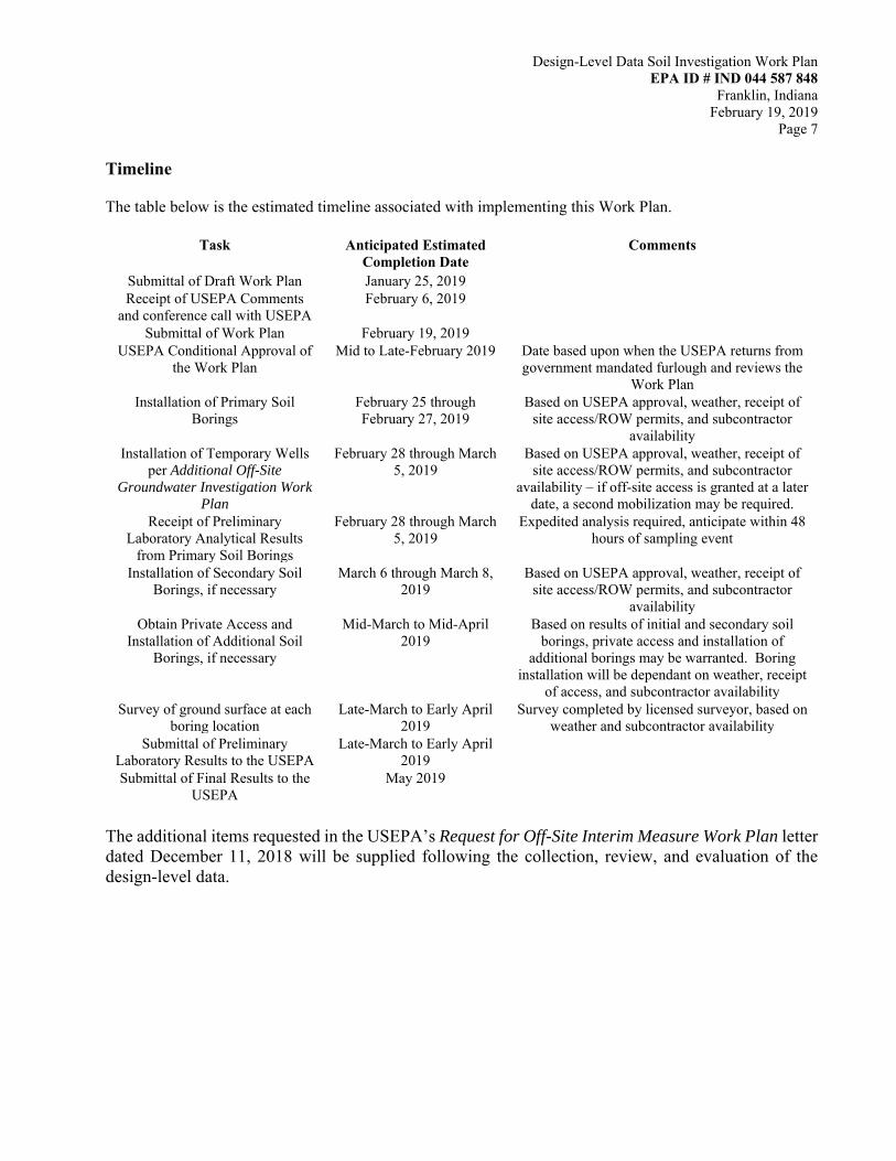
Timeline The table below is the estimated timeline associated with implementing this Work Plan.
Task Anticipated Estimated Completion Date
Comments
Submittal of Draft Work Plan January 25, 2019 Receipt of USEPA Comments
and conference call with USEPA February 6, 2019
Submittal of Work Plan February 19, 2019 USEPA Conditional Approval of
the Work Plan Mid to Late-February 2019 Date based upon when the USEPA returns from
government mandated furlough and reviews the Work Plan
Installation of Primary Soil Borings
February 25 through February 27, 2019
Based on USEPA approval, weather, receipt of site access/ROW permits, and subcontractor
availability Installation of Temporary Wells
per Additional Off-Site Groundwater Investigation Work
Plan
February 28 through March 5, 2019
Based on USEPA approval, weather, receipt of site access/ROW permits, and subcontractor
availability – if off-site access is granted at a later date, a second mobilization may be required.
Receipt of Preliminary Laboratory Analytical Results
from Primary Soil Borings
February 28 through March 5, 2019
Expedited analysis required, anticipate within 48 hours of sampling event
Installation of Secondary Soil Borings, if necessary
March 6 through March 8, 2019
Based on USEPA approval, weather, receipt of site access/ROW permits, and subcontractor
availability Obtain Private Access and
Installation of Additional Soil Borings, if necessary
Mid-March to Mid-April 2019
Based on results of initial and secondary soil borings, private access and installation of
additional borings may be warranted. Boring installation will be dependant on weather, receipt
of access, and subcontractor availability Survey of ground surface at each
boring location Late-March to Early April
2019 Survey completed by licensed surveyor, based on
weather and subcontractor availability Submittal of Preliminary
Laboratory Results to the USEPA Late-March to Early April
2019
Submittal of Final Results to the USEPA
May 2019
The additional items requested in the USEPA’s Request for Off-Site Interim Measure Work Plan letter dated December 11, 2018 will be supplied following the collection, review, and evaluation of the design-level data.

Design-Level Data Soil Investigation Work Plan EPA ID # IND 044 587 848
Franklin, Indiana February 19, 2019
Page 8
Please do not hesitate to contact the undersigned with questions or if you need additional information regarding this submittal. Sincerely, IWM CONSULTING GROUP, LLC
Christopher D. Parks, LPG #2169 Senior Project Manager
Bradley E. Gentry, LPG #2165 Vice President/Brownfield Coordinator cc: Mr. Joseph Bianchi, Amphenol (electronic only)
Carolyn Bury, U.S. EPA Region 5, RRB CAS2 (electronic only) Bhooma Sundar, U.S. EPA Region 5, RRB CAS2 (electronic only) Conor Neal, U.S. EPA Region 5, RRB CAS2 (electronic only)

Figures

FORMER ARVIN MERITOR FACILITY
_.,'"4c"'J�ODUCTION SERVICES PREMIER AG
FdMtliR F NKLIN� POWER PRODUCTS. ,,.
- PROPERTY LINE (APPROXIMATE)
----- PRELIMINARY STUDY AREA BOUNDARY
0' 200'
SCALE IN FEET
DRAWN BY: L. STRUM
DATE: 9/27/99
REVISED: 09/10/2018
HWPA#111291-01
DWG. NO.111291S1
• <( •
I� <( . (.)
I!. FORMER AMPHENOL
FACILITY AGRICULTURAL FIELD
FIGURE 1 PRELIMINARY STUDY
AREA MAP
- SYSTEM
BUILDING
FORMER AMPHENOL RFI/CMS 980 HURRICANE ROAD
FRANKLIN, INDIANA 1WM ,a-1: f-i•l§i WilfM•X•I [t

') T
T T
LEGEND
• ABANDONED MONITORING WELL $ MONITORING WELL lill RECOVERY WELL 0 SANITARY SEWER MANHOLE
0 STORM SEWER MANHOLE
T
• • • HAMIL TON AVEN
250052 (9�38')
.---------------------------1
MW-34
T T
(VCP) VITREOUS CLAY PIPE PROPOSED SOIL
PROPERTY LINE (APPROXIMATE) D RESIDENTIAL HOME
* DETACHED GARAGES & SHEDS NOT SHOWN .. SEWER LINE BREAK • BORING LOCATION
STORM SEWER D NON-RESIDENTIAL STRUCTURE .. SEWER LINE CRACK
'Y PROPOSED SANITARY SEWER � SEWER MATERIAL CHANGE SECONDARY SOIL 0/H POWER
* SEWER INFORMATION OBTAINED FROM 2015 BORING LOCATION
(SEWER MAIN INVERT DEPTH AT MANHOLE IN FEET) D PRIMARY BUILDING WALLS
SEWER VIDEO LOG FOR FRANKLIN DPW.
t I
O' 3 0'
SCALE IN FEET
DRAWN BY: L. STRUM
DA TE: 9/27/9 9 FIGURE 2
REVISED: 01 /23/201 9 UPPER FORSYTHE ST.
,-H_w
_PA
_#
_1
_1 1
_29
_1-
_01_-----1SOIL BORING LOCATION MAP
DWG. NO.11 1 291S1
FORMER AMPHENOL RFI/CMS 980 HURRICANE ROAD
FRANKLIN, INDIANA 1WM ,a-1: f-i•l§i WilfM•X•I [t

LEGEND
• ABANDONED MONITORING WELL $ MONITORING WELL lill RECOVERY WELL 0 SANITARY SEWER MANHOLE
0 STORM SEWER MANHOLE
-
(SEWER MAIN INVERT DEPTH AT MANHOLE IN FEET)
t I
O' 30'
SCALE IN FEET
DRAWN BY: L. STRUM
DATE: 9/27/99
REVISED: 01/23/2019
HWPA#111291-01
DWG. NO.111291S1
--a_
0 > --
• .TMW-31 eT
--a_
0 > --
-
PROPERTY LINE (APPROXIMATE) D RESIDENTIAL HOME
* DETACHED GARAGES & SHEDS NOT SHOWN
STORM SEWER D NON-RESIDENTIAL STRUCTURE SANITARY SEWER
0/H POWER D PRIMARY BUILDING WALLS
(VCP)
(VCP) VITREOUS CLAY PIPE
• PROPOSED SOIL .. BORING LOCATION SEWER LINE BREAK .. SEWER LINE CRACK
'Y PROPOSED
� SEWER MATERIAL CHANGE SECONDARY SOIL
* SEWER INFORMATION OBTAINED FROM 2015 BORING LOCATION
SEWER VIDEO LDG FOR FRANKLIN DPW.
FIGURE 3
UPPER-MIDDLE FORSYTHE ST.
SOIL BORING LOCATION MAP
FORMER AMPHENOL RFI/CMS 980 HURRICANE ROAD
FRANKLIN, INDIANA 1WM ,a-1: f-i•l§i WilfM•X•I [t

LEGEND
• ABANDONED MONITORING WELL $ MONITORING WELL lill RECOVERY WELL 0 SANITARY SEWER MANHOLE
0 STORM SEWER MANHOLE (SEWER MAIN INVERT DEPTH AT MANHOLE IN FEET)
t I
O' 30'
SCALE IN FEET
DRAWN BY: L. STRUM
DATE: 9/27/99
REVISED: 01/23/2019
HWPA#111291-01
DWG. NO.111291S1
(10.16') ROSS COURT
a.. � "'
>
250030 (10.05')
PROPERTY LINE (APPROXIMATE)
STORM SEWER
SANITARY SEWER
0/H POWER
a.. >
250020
MW-32
D RESIDENTIAL HOME * DETACHED GARAGES & SHEDS NOT SHOWN
D NON-RESIDENTIAL STRUCTURE
D PRIMARY BUILDING WALLS
(VCP) VITREOUS CLAY PIPE
• PROPOSED SOIL .. BORING LOCATION SEWER LINE BREAK .. SEWER LINE CRACK
'Y PROPOSED
� SEWER MATERIAL CHANGE SECONDARY SOIL
* SEWER INFORMATION OBTAINED FROM 2015 BORING LOCATION
SEWER VIDEO LOG FOR FRANKLIN DPW.
FIGURE4
LOWER-MIDDLE FORSYTHE ST.
SOIL BORING LOCATION MAP
FORMER AMPHENOL RFI/CMS 980 HURRICANE ROAD
FRANKLIN, INDIANA 1WM ,a-1: f-i•l§i WilfM•X•I [t

LEGEND
• ABANDONED MONITORING WELL $ MONITORING WELL lill RECOVERY WELL 0 SANITARY SEWER MANHOLE
0 STORM SEWER MANHOLE
PROPERTY LINE (APPROXIMATE)
STORM SEWER
SANITARY SEWER
0/H POWER
MW-32
z ■
., 0 ;a en -I I m en -I ;a m m -I
D RESIDENTIAL HOME * DETACHED GARAGES & SHEDS NOT SHOWN
D NON-RESIDENTIAL STRUCTURE
(VCP) VITREOUS CLAY PIPE .. SEWER LINE BREAK .. SEWER LINE CRACK
� SEWER MATERIAL CHANGE
* SEWER INFORMATION OBTAINED FROM 2015
POW
• PROPOSED SOIL BORING LOCATION
'Y PROPOSED SECONDARY SOIL BORING LOCATION
(SEWER MAIN INVERT DEPTH AT MANHOLE IN FEET) D PRIMARY BUILDING WALLS
SEWER VIDEO LOG FOR FRANKLIN DPW.
t I
O' 3 0'
SCALE IN FEET
DRAWN BY: L. STRUM
DA TE: 9/27/9 9 FIGURE 5
REVISED: 01 /23/201 9 LOWER FORSYTHE ST.
,-H_w
_PA
_#
_1
_1 1
_29
_1-
_01_-----1SOIL BORING LOCATION MAP
DWG. NO.11 1 291S1
FORMER AMPHENOL RFI/CMS 980 HURRICANE ROAD
FRANKLIN, INDIANA 1WM ,a-1: f-i•l§i WilfM•X•I [t

-·-'-·MW-28
zo mr ::;o
MW-3
•
M
I
�-----------------------;,
----
----
----
/'
-2 3 _,,
_,,
_,,-,,-✓--/
L---------11!7�M�-22 SS-N RTH (15.08')
EQUIPMENT
BUILDING MW-
r
I ·o Ir ·o I
•
RWJ ,�
MW-1 2
z m
�
RW-3
W-25 �RW-2 �
�
RW-1
(14.60') Ss-s· Tlj 50056 · -· -· · -· -· -· --
250055
HAMIL TON AVENUE (9.35') 250090
LEGEND
• ABANDONED MONITORING WELL $ MONITORING WELL lill RECOVERY WELL 0 SANITARY SEWER MANHOLE
0 STORM SEWER MANHOLE (SEWER MAIN INVERT DEPTH AT MANHOLE IN FEET)
O' 30'
SCALE IN FEET
DRAWN BY: L. STRUM
DATE: 9/27/99
REVISED: 02/11/2019
HWPA#111291-01
DWG. NO.111291S1
PROPERTY LINE (APPROXIMATE)
STORM SEWER
SANITARY SEWER
0/H POWER
�
IT-2
D RESIDENTIAL HOME * DETACHED GARAGES & SHEDS NOT SHOWN
D NON-RESIDENTIAL STRUCTURE
D PRIMARY BUILDING WALLS
MW-35
(VCP) VITREOUS CLAY PIPE
• PROPOSED SOIL .. SEWER LINE BREAK BORING LOCATION .. SEWER LINE CRACK
� PROPOSED
� SEWER MATERIAL CHANGE SECONDARY SOIL BORING LOCATION
* SEWER INFORMATION OBTAINED FROM 2015
SEWER VIDEO LDG FOR FRANKLIN DPW.
FIGURE 6
ONSITE PROPOSED BORING
LOCATION MAP
FORMER AMPHENOL RFI/CMS 980 HURRICANE ROAD
FRANKLIN, INDIANA 1WM ,a-1: f-i•l§i WilfM•X•I [t

Attachments

Attachment A
USEPA Letter Dated December 11, 2018

UNITED STATES ENVIRONMENTAL PROTECTION AGENCY
REGION 5
77 WEST JACKSON BOULEVARD
CHICAGO, IL 60604-3590
REPLY TO THE ATTENTION OF
LU-16J
Via E-mail and Certified Mail 7009 1680 0000 7671 1777 RETURN RECEIPT REQUESTED
December 11, 2018
Mr. Joseph M. Bianchi Group EHS Manager Amphenol Corporation 40-60 Delaware Avenue Sidney, NY 13838
Mr. Matt Kupcak Director, Global Environmental Programs BorgWarner Inc. 3850 Hamlin Road Auburn Hills, Ml 48326
Subject: Franklin Power Products, lnc./Amphenol Corporation Request for Off-Site Interim Measure Work Plan Administrative Order on Consent, Docket # R8H-5-99-002 EPA ID# IND 044 587 848
Dear Mr. Bianchi and Mr. Kupcak:
Under Section VIII, Paragraph N (Additional Work) of the RCRA 3008(h) Administrative Order on Consent dated November 24, 1998 (Order), EPA has determined that
Respondents Amphenol Corporation and Franklin Power Products, Inc. (FPP/Amphenol) must perform Additional Work at the facility at 980 Hurricane Road in Franklin, Indiana ("Facility" or "Site"). The Additional Work described in this letter is necessary to meet the purposes of the Order, including but not limi_ted to, assuring the selected corrective measures address the actual and potential threats to human health and the environment presented by the actual and potential releases of hazardous wastes or hazardous constituents at or from the Facility.
Recent environmental media sampling along North Forsythe St. and portions of Hamilton Ave., Ross Court, and Glendale Dr. south of the former Amphenol Corp. facility identified significantly elevated levels of volatile organic compound (VOC) vapors
in sewer bedding soil, street rights-of-way soil, sewers, and VOC contamination of groundwater. VOC concentrations are elevated above vapor intrusion risk-based screening levels; groundwater is also elevated above maximum contaminant levels.
Recycled/Recyclable • Printed with Vegetable Oil Based Inks on 100% Recycled Paper (100% Post-Consumer)

Amphenol Corporation (Amphenol) has indicated its intent to perform an interim measure (IM) remedy to address residual off-Site contamination in the neighborhood south of the Facility, referred to as the Study Area in Corrective Action documents for this Site. Amphenol described the proposed remedy conceptually to EPA as the removal of contaminated media around the sewer system and replacement of sewers along a portion of North Forsythe St. to eliminate or mitigate risk of vapor intrusion. However, it is unclear that off-Site contaminated media needing remediation is confined
to North Forsythe St. Additional sampling is needed to identify the areal extent to be covered by the remedial design plan. This letter requests that Amphenol submit a detailed remedial design work plan ("work plan") including such sampling for EPA approval. Upon approval, EPA will require that Amphenol begin work as soon as possible.
The purpose of the sampling in the neighborhood south of the Facility was to determine the condition of historically contaminated off-site environmental media in the Study Area, and whether residual VOC contaminated media exceeded risk-based residential screening values. The sampling was also performed to assess the extent of off-Site impacts. However, the investigation was not comprehensive, and the complete extent of off-Site impacts was not determined. The sample results are being used to identify buildings, primarily homes, needing indoor air vapor intrusion sampling. To date, of the subset of homes sampled, some have sub-slab and indoor air VOC levels above IDEM Risk-based Closure Levels and need sub-slab vapor d_epressurization systems and other remedial measures, underscoring the need for remediation of impacted media.
Summary of Requested Work
Amphenol Corp must prepare and submit a work plan to EPA that describes its proposed approach to interim measures to address off-Site contaminated environmental media. The work plan must include proposed risk-based Corrective Action objectives for incorporation into the remedial design.
The work plan must include, but not be limited to, the elements described below.
1) Design-level data Insufficient information is currently available to design the remedy. Amphenol must collect design-level information, including sampling to establish the proposed vertical, horizontal, eastern/western and southern extent of the remedial area. The work plan must propose the approach to delineating the extent of VOC-impacted media, including field and analytical methods. The impacted media to be analyzed includes sewer bedding soil, street rights-of-way
2

soil, and groundwater. Data collection may include sampling on residential and other private properties.
Amphenol may prepare and submit a sampling plan to collect design-level data to EPA in advance of the final proposed work plan. Data from the sampling event must be provided to EPA upon receipt and third-party validation. EPA will then determine whether additional characterization is required to determine the
remedial extent or to refine the remedial design elements.
2) Corrective Action Objectives Amphenol must propose risk-based Corrective Action Objectives (CAOs) for each medium and incorporate these into the remedial design. For example, because contaminated soil is a source of contamination to groundwater, the CAO for soil should meet groundwater protection standards and the CAO for groundwater should include MCLs and VISLs. The CAOs will be used along with confirmation sampling data following cleanup to verify whether the IM is complete.
3) Construction Design Amphenol must provide a complete description of construction design for all phases of the remediation, including engineering design drawings, waste disposal characterization data and profiles, and comprehensive documentation of instructions to contractors. All planned restoration must be included and clean backfill is required. In addition, as-built drawings are required upon completion of construction for EPA review and approval.
4) Materials Management Plan (MMP) Amphenol must include a MMP for all contaminated materials to be excavated and handled that require proper disposal in accordance with local, State, and Federal regulations based on waste classification. The MMP must include a plan for handling any non-aqueous phase liquids encountered.
5) Best Management Practices (BMPs) Amphenol must incorporate BMPs into the construction plan, including the monitoring and controlling releases of VOC vapors and fugitive dust, and other BMPs such as erosion control. Details such as an air monitoring plan with contingency measures must be included.
6) Storm Water Pollution Prevention Plan (SWPPP) Amphenol must prepare and submit a SWPPP to IDEM and obtain a permit for Storm Water Discharges from Construction Site Activities. EPA must be copied on the proposed plan.
3

7) Permits The work plan must include a list of permits needed and obtained, including for excavation and traffic control. All needed permits must be obtained prior to mobilization to the Site.
8) Access The work plan must include access needs and Amphenol's plan to obtain access.
9) Public notification The work plan must include how the public will be notified of work including schedules, and whether sewer connections will be interrupted and the plan for accommodating households during periods of interruption. The plan should include a description of how Amphenol will coordinate with the City of
Franklin.
1 0)Confirmation sampling Following removal, Amphenol must perform confirmation sampling to verify that the excavation limits are consistent with the CAOs.
11)Existing Structures and Utilities The plan must include measures for protection and/or replacement of existing structures and property, including utility infrastructure, driveways, sidewalks, yards, trees, etc.
12)Health and Safety Plan (HSP) The work plan must include a HSP that covers controlling potential exposures in the neighborhood, hazardous materials training requirements of contractors, and a traffic safety plan.
13)Schedule The plan must include a proposed schedule of all activities.
Quality Assurance
Previously approved quality assurance (QA) measures may be referenced in the work plan; references must be explicit. New QA measures must be proposed in the work plan. Please refer to EPA's QA/R-5, EPA Requirements for Quality Assurance Project Plans (EPA 2001) found at https://www.epa.gov/sites/production/files/2016-06/documents/r5-final 0.pdf. All samples must be analyzed by a laboratory with appropriate ELAP certification, as specified in the guidance. Please also refer to Guidance for Quality Assurance Project Plans, EPA QA/G-5 (EPA 2002) when developing the QA/Quality Control portions of the Work Plan.
4
By January 25, 2019, EPA requests that you submit an Off-Site Interim Measure Remedial Design Work Plan as described above.
If you have any questions, please contact me at (312) 886-3020.
Sincerely,
�� Carolyn Bury Project Manager Corrective Action Section 2 Remediation and Re-use Branch
ecc: Brad Gentry, IWM Consulting Group, LLC. Don Stilz, I DEM Bhooma Sundar, RRB CAS2 Conor Neal, RRB CAS2 Motria Caudill, ATSDR
5

Attachment B
IWM Consulting SOPs

SOP Group G Revision 0.0
SOP Group G - Page i
SOP Group G
Standard Operating Procedures for Soil Sampling
TABLE OF CONTENTS
INTRODUCTION ................................................................................................................................. 1
SOP G.1 METHOD SUMMARY ....................................................................................................... 1
SOP G.2 SAMPLING PRESERVATION, CONTAINERS, HANDLING AND STORAGE ......... 1
SOP G.3 INTERFERENCE AND POTENTIAL PROBLEMS ......................................................... 1
SOP G.4 EQUIPMENT ....................................................................................................................... 2
SOP G.5 REAGENTS .......................................................................................................................... 2
SOP G.6 PROCEDURES .................................................................................................................... 3
G.6.1 PREPERATION ..................................................................................................................... 3 G.6.2 SAMPLE COLLECTION ........................................................................................................... 3
G.6.2.1 Surface Soil Samples .............................................................................................................................. 3 G.6.2.2 Sampling at Depth with Augers .............................................................................................................. 4 G.6.2.3 Sampling at Depth with a Split Spoon (Barrel) Sampler ........................................................................ 6 G.6.2.4 Sampling at Depth Using a Direct-Push Sampler .................................................................................. 7 G.6.2.4 Test Pit/Trench Excavation ..................................................................................................................... 8 G.6.2.5 Terra Core Sampler - VOC Soil Sample Collection ................................................................................ 9 G.6.2.6 Non-VOC Soil Sample Collection .......................................................................................................... 11
SOP G.7 QUALITY ASSURANCE/QUALITY CONTROL ...................................................... 12
SOP G.8 HEALTH AND SAFETY ................................................................................................ 12
SOP G.9 REFERENCES ................................................................................................................. 12

SOP Group G Revision 0.0
SOP Group G - Page 1
SOP Group G
Standard Operating Procedures for Soil Sampling
Introduction The purpose of this standard operating procedure (SOP) is to describe the procedures for the collection of representative soil samples. Analysis of soil samples may determine whether concentrations of specific pollutants exceed established action levels, or if the concentrations of pollutants present a risk to public health, welfare, or the environment. These are standard (i.e., typically applicable) operating procedures which may be varied or changed as required, dependent upon site conditions, equipment limitations or limitations imposed by the procedure. In all instances, the actual procedures used should be documented and described in an appropriate site report. Mention of trade names or commercial products does not constitute an endorsement or recommendation for use. SOP G.1 Method Summary Soil samples may be collected using a variety of methods and equipment depending on the depth of the desired sample, the type of sample required (disturbed vs. undisturbed), and the soil type. Near-surface soils may be easily sampled by hand or using a spade, trowel, or scoop. Sampling at greater depths may be performed using a hand auger, continuous flight auger, a split-spoon, or, if required, a drill rig, direct-push sampler or, a backhoe or excavator bucket. SOP G.2 Sampling Preservation, Containers, Handling and Storage Chemical preservation of solids is based on analytical method requirements. Samples should be cooled and protected from sunlight to minimize any potential reaction. The amount of sample to be collected, proper sample container type and preservative are discussed in SOP Group H. SOP G.3 Interference and Potential Problems There are two primary potential problems associated with soil sampling - cross contamination of samples and improper sample collection. Cross contamination problems can be eliminated or minimized through the use of dedicated sampling equipment. If this is not possible or practical, then decontamination of sampling equipment is necessary. Improper sample collection can involve using contaminated equipment, disturbance of the

SOP Group G Revision 0.0
SOP Group G - Page 2
matrix resulting in compaction of the sample, or inadequate homogenization of the samples where required, resulting in variable, non-representative results. SOP G.4 Equipment Typical soil sampling equipment includes some or all of the following:
Maps/plot plan Safety equipment (including PPE), as specified in the site-specific Health and Safety Plan Survey equipment or global positioning system (GPS) to locate sampling points Tape measure Survey stakes or flags Camera and film Stainless steel, plastic, or other appropriate homogenization bucket, bowl or pan Appropriate size sample containers Ziplock plastic bags Site logbook Labels Chain of Custody records and custody seals Field data sheets and sample labels Cooler(s) Ice Decontamination supplies/equipment Canvas or plastic sheet Spade or shovel Spatula Scoop Plastic or stainless steel spoons Trowel(s) Continuous flight (screw) auger Bucket auger Post hole auger Extension rods T-handle Sampling trier Thin wall tube sampler Drill rig or direct-push sampler Split spoons Vehimeyer soil sampler outfit Backhoe

SOP Group G Revision 0.0
SOP Group G - Page 3
SOP G.5 Reagents When obtaining soil samples for VOC analysis, the soil samples must be obtained in accordance with Sampling Method 5035. Consequently, Terra Core™ sampling Kits will need to be utilized during the sampling activities. The Terra Core™ Sampling Kits include two pre-weighed (tared) and labeled 40-mL VOA glass vial containing a magnetic stir bar and 5-mL of reagent (distilled) water. These containers will be utilized for low level VOC samples. The kits also include one pre-weighed and labeled 40-mL VOA glass vial containing 5-mL of MeOH for medium to high level VOC samples. Avoid splashing any preservative, if present, out of the sample container by holding the container at an angle while slowly extruding the soil core into the sample container. Do not immerse the sampling device into the preservative. Reagents are not typically used for the preservation of non-volatile soil samples. SOP G.6 Procedures G.6.1 Preparation Determine the extent of the sampling effort, the sampling methods to be employed, and the types and amounts of equipment and supplies required. Obtain project-specific sampling objectives from the Project Manager. Obtain necessary sampling and monitoring equipment. Decontaminate or pre-clean equipment, and ensure that it is in working order. Prepare schedules and coordinate with staff, client, and regulatory agencies, if appropriate. Perform a general site survey prior to site entry in accordance with the site specific Health and Safety Plan. Use stakes, flagging, or spray paint to identify and mark all sampling locations. Specific site factors, including extent and nature of contaminant, should be considered when selecting sample location. If required, the proposed locations may be adjusted based on site access, property boundaries, utilities, and surface obstructions. All staked locations should be utility-cleared by the property owner or the Field Team Leader prior to soil sampling; and utility clearance should always be confirmed before beginning work.

SOP Group G Revision 0.0
SOP Group G - Page 4
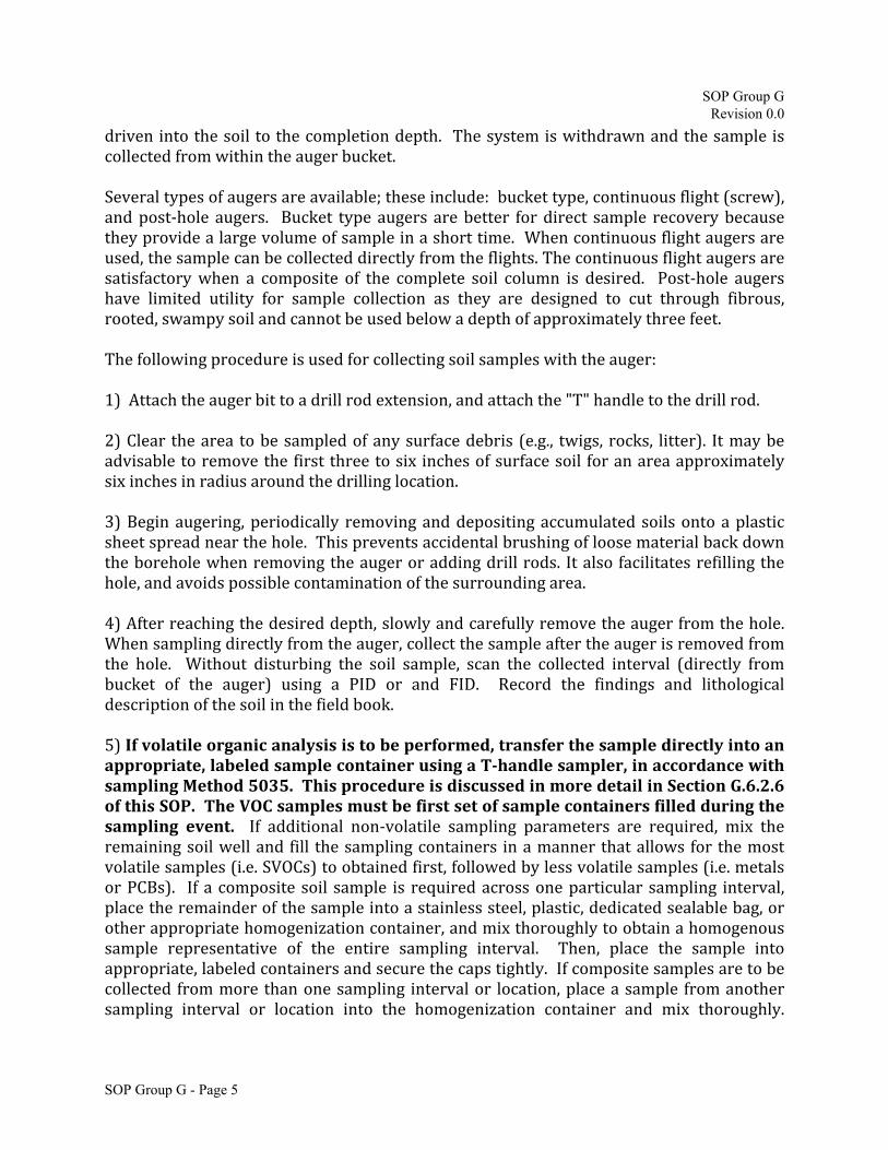
G.6.2 Sample Collection G.6.2.1 Surface Soil Samples Collection of samples from near-surface soil can be accomplished with tools such as spades, shovels, trowels, and scoops. Surface material is removed to the required depth and a stainless steel or plastic scoop is then used to collect the sample. This method can be used in most soil types but is limited to sampling at or near the ground surface. Accurate, representative samples can be collected with this procedure depending on the care and precision demonstrated by the sample team member. A flat, pointed mason trowel to cut a block of the desired soil is helpful when undisturbed profiles are required. Tools plated with chrome or other materials should not be used. Plating is particularly common with garden implements such as potting trowels. The following procedure is used to collect surface soil samples: Carefully remove the top layer of soil or debris to the desired sample depth with a pre-cleaned spade. Using a pre-cleaned, stainless steel scoop, plastic spoon, or trowel, remove and discard a thin layer of soil from the area which came in contact with the spade. Ifvolatileorganicanalysis is tobeperformed, transfer thesampledirectly intoanappropriate,labeledsamplecontainerusingaT‐handlesamplerinaccordancewithsamplingMethod5035.Thisprocedureisdiscussedinmoredetailin SectionG.6.2.6ofthisSOP.TheVOCsamplesmustbefirstsetofsamplecontainersfilledduringthesampling event. If additional non-volatile sampling parameters are required, mix the remaining soil well and fill the sampling containers in a manner that allows for the most volatile samples (i.e. SVOCs) to obtained first, followed by less volatile samples (i.e. metals or PCBs). If a composite soil sample is required across one particular sampling interval, place the remainder of the sample into a stainless steel, plastic, dedicated sealable bag, or other appropriate homogenization container, and mix thoroughly to obtain a homogenous sample representative of the entire sampling interval. Then, place the sample into appropriate, labeled containers and secure the caps tightly. If composite samples are to be collected from more than one sampling interval or location, place a sample from another sampling interval or location into the homogenization container and mix thoroughly. When compositing is complete, place the sample into appropriate, labeled containers and secure the caps tightly. G.6.2.2 Sampling at Depth with Augers This system consists of an auger and a series of extensions, and a "T" handle. The auger is used to bore a hole to a desired sampling depth, and is then withdrawn. The sample may be collected directly from the auger. The system is then lowered down the borehole, and
SOP Group G Revision 0.0
SOP Group G - Page 5
driven into the soil to the completion depth. The system is withdrawn and the sample is collected from within the auger bucket. Several types of augers are available; these include: bucket type, continuous flight (screw), and post-hole augers. Bucket type augers are better for direct sample recovery because they provide a large volume of sample in a short time. When continuous flight augers are used, the sample can be collected directly from the flights. The continuous flight augers are satisfactory when a composite of the complete soil column is desired. Post-hole augers have limited utility for sample collection as they are designed to cut through fibrous, rooted, swampy soil and cannot be used below a depth of approximately three feet. The following procedure is used for collecting soil samples with the auger:
1) Attach the auger bit to a drill rod extension, and attach the "T" handle to the drill rod. 2) Clear the area to be sampled of any surface debris (e.g., twigs, rocks, litter). It may be advisable to remove the first three to six inches of surface soil for an area approximately six inches in radius around the drilling location. 3) Begin augering, periodically removing and depositing accumulated soils onto a plastic sheet spread near the hole. This prevents accidental brushing of loose material back down the borehole when removing the auger or adding drill rods. It also facilitates refilling the hole, and avoids possible contamination of the surrounding area. 4) After reaching the desired depth, slowly and carefully remove the auger from the hole. When sampling directly from the auger, collect the sample after the auger is removed from the hole. Without disturbing the soil sample, scan the collected interval (directly from bucket of the auger) using a PID or and FID. Record the findings and lithological description of the soil in the field book. 5) Ifvolatileorganicanalysisistobeperformed,transferthesampledirectlyintoanappropriate,labeledsamplecontainerusingaT‐handlesampler,inaccordancewithsamplingMethod5035.Thisprocedureisdiscussedinmoredetailin SectionG.6.2.6ofthisSOP.TheVOCsamplesmustbefirstsetofsamplecontainersfilledduringthesampling event. If additional non-volatile sampling parameters are required, mix the remaining soil well and fill the sampling containers in a manner that allows for the most volatile samples (i.e. SVOCs) to obtained first, followed by less volatile samples (i.e. metals or PCBs). If a composite soil sample is required across one particular sampling interval, place the remainder of the sample into a stainless steel, plastic, dedicated sealable bag, or other appropriate homogenization container, and mix thoroughly to obtain a homogenous sample representative of the entire sampling interval. Then, place the sample into appropriate, labeled containers and secure the caps tightly. If composite samples are to be collected from more than one sampling interval or location, place a sample from another sampling interval or location into the homogenization container and mix thoroughly.
SOP Group G Revision 0.0
SOP Group G - Page 6
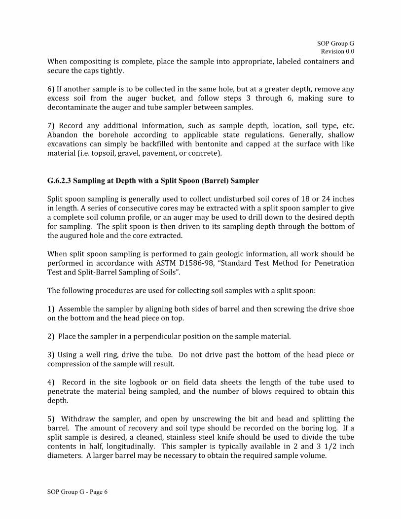
When compositing is complete, place the sample into appropriate, labeled containers and secure the caps tightly. 6) If another sample is to be collected in the same hole, but at a greater depth, remove any excess soil from the auger bucket, and follow steps 3 through 6, making sure to decontaminate the auger and tube sampler between samples. 7) Record any additional information, such as sample depth, location, soil type, etc. Abandon the borehole according to applicable state regulations. Generally, shallow excavations can simply be backfilled with bentonite and capped at the surface with like material (i.e. topsoil, gravel, pavement, or concrete).
G.6.2.3 Sampling at Depth with a Split Spoon (Barrel) Sampler Split spoon sampling is generally used to collect undisturbed soil cores of 18 or 24 inches in length. A series of consecutive cores may be extracted with a split spoon sampler to give a complete soil column profile, or an auger may be used to drill down to the desired depth for sampling. The split spoon is then driven to its sampling depth through the bottom of the augured hole and the core extracted. When split spoon sampling is performed to gain geologic information, all work should be performed in accordance with ASTM D1586-98, “Standard Test Method for Penetration Test and Split-Barrel Sampling of Soils”. The following procedures are used for collecting soil samples with a split spoon: 1) Assemble the sampler by aligning both sides of barrel and then screwing the drive shoe on the bottom and the head piece on top. 2) Place the sampler in a perpendicular position on the sample material. 3) Using a well ring, drive the tube. Do not drive past the bottom of the head piece or compression of the sample will result. 4) Record in the site logbook or on field data sheets the length of the tube used to penetrate the material being sampled, and the number of blows required to obtain this depth. 5) Withdraw the sampler, and open by unscrewing the bit and head and splitting the barrel. The amount of recovery and soil type should be recorded on the boring log. If a split sample is desired, a cleaned, stainless steel knife should be used to divide the tube contents in half, longitudinally. This sampler is typically available in 2 and 3 1/2 inch diameters. A larger barrel may be necessary to obtain the required sample volume.

SOP Group G Revision 0.0
SOP Group G - Page 7
6) Without disturbing the soil sample, scan the collected interval (directly from the split spoon) using a PID or and FID. Record the findings and lithological description of the soil in the field book and select the sample displaying the highest field screen reading, and/or from other areas that indicate the potential for contamination. Be certain to understand the project specific objective and sampling rationale prior to determining your sampling interval. 7) Without disturbing the core, transfer it to appropriate labeled sample container(s) and seal tightly. If volatile organic analysis is to be performed, transfer the sampledirectly intoanappropriate, labeledsamplecontainerusingaT‐handlesampler inaccordancewithsamplingMethod5035.Thisprocedureisdiscussedinmoredetailin SectionG.6.2.6ofthisSOP.TheVOCsamplesmustbefirstsetofsamplecontainersfilled during the sampling event. If additional non-volatile sampling parameters are required, mix the remaining soil well and fill the sampling containers in a manner that allows for the most volatile samples (i.e. SVOCs) to obtained first, followed by less volatile samples (i.e. metals or PCBs). If a composite soil sample is required across one particular sampling interval, place the remainder of the sample into a stainless steel, plastic, dedicated sealable bag, or other appropriate homogenization container, and mix thoroughly to obtain a homogenous sample representative of the entire sampling interval. Then, place the sample into appropriate, labeled containers and secure the caps tightly. If composite samples are to be collected from more than one sampling interval or location, place a sample from another sampling interval or location into the homogenization container and mix thoroughly. When compositing is complete, place the sample into appropriate, labeled containers and secure the caps tightly. 8) Record any additional information, such as sample depth, location, soil type, etc. Abandon the borehole according to applicable state regulations. Generally, shallow excavations can simply be backfilled with bentonite and capped at the surface with like material (i.e. topsoil, gravel, pavement, or concrete). G.6.2.4 Sampling at Depth Using a Direct-Push Sampler Direct-push soil sampling is accomplished using an impact-driven or truck-mounted Geoprobe® or EarthProbe® type drill rig equipped with a probe-drive, soil-sampling system. Soil samples are retrieved by hydraulically driving a sampling probe rod to the desired depth. Depending on the type of system employed, the samplers may either take continuous samples or the probe rod may be used to obtain samples at discrete intervals. The sample remains sealed within an inner clear-PVC sample tube, contained in the sampling probe as it is driven to the desired depth. As the probe is driven through the desired sampling interval, the soil sample is forced upward past a cutting shoe on the end of the drive rod. As the soil passes upwards, it enters a disposable, clear-PVC liner attached to the cutting shoe. Soil samples retrieved in this manner can be characterized for texture, moisture content, color, etc., and selected samples can be retained for laboratory analysis.

SOP Group G Revision 0.0
SOP Group G - Page 8
The following procedures are used for collecting soil samples with a direct-push sampler: 1) After driving the sampler through the sample interval the probe rods and/or sampler is extracted from the borehole. 2) The cutting shoe is removed allowing for the removal of the clear-plastic liner containing the sample. 3) Place the sampler liner horizontally on a clean working surface (e.g., a plastic table). Record in the site logbook or on field data sheets the length of the sample interval, the sample recovery, and any other pertinent information and observations. 4) Utilize a clean, box-cutter style knife blade to open the plastic sampling tube lengthwise. Note: occasionally some work plans may not call for cutting the sampling tube lengthwise and instead will call for the cutting of one or more perpendicular segments from sampling tube, which will then have the ends capped and sealed with the sample remaining intact and undisturbed within the selected section of sample liner. 5) Without disturbing the soil sample, scan the collected interval (directly from acetate liner) using a PID or an FID. Record the findings and lithological description of the soil in the field book and select the sample displaying the highest field screen reading, and/or from other areas that indicate the potential for contamination. Be certain to understand the project specific objective and sampling rationale prior to determining your sampling interval. 6)Ifvolatileorganicanalysisistobeperformed,transferthesampledirectlyintoanappropriate,labeledsamplecontainerusingaT‐handlesampler,inaccordancewithsamplingMethod5035.Thisprocedureisdiscussedinmoredetailin SectionG.6.2.6ofthisSOP.TheVOCsamplesmustbefirstsetofsamplecontainersfilledduringthesampling event. If additional non-volatile sampling parameters are required, mix the remaining soil well and fill the sampling containers in a manner that allows for the most volatile samples (i.e. SVOCs) to obtained first, followed by less volatile samples (i.e. metals or PCBs). If a composite soil sample is required across one particular sampling interval, place the remainder of the sample into a stainless steel, plastic, dedicated sealable bag, or other appropriate homogenization container, and mix thoroughly to obtain a homogenous sample representative of the entire sampling interval. Then, place the sample into appropriate, labeled containers and secure the caps tightly. If composite samples are to be collected from more than one sampling interval or location, place a sample from another sampling interval or location into the homogenization container and mix thoroughly. When compositing is complete, place the sample into appropriate, labeled containers and secure the caps tightly.

SOP Group G Revision 0.0
SOP Group G - Page 9
7) Record any additional information, such as sample depth, location, soil type, etc. Abandon the borehole according to applicable state regulations. Generally, shallow excavations can simply be backfilled with bentonite and capped at the surface with like material (i.e. topsoil, gravel, pavement, or concrete). G.6.2.5 Test Pit/Trench Excavation A backhoe can be used to remove sections of soil, when detailed examinations of soil characteristics are required. The following procedures are used for collecting soil samples from test pits or trenches: 1) Prior to any excavation with a backhoe, it is important to ensure that all sampling locations are clear of overhead and buried utilities. 2) Review the site specific Health & Safety plan and ensure that all safety precautions including appropriate monitoring equipment are installed as required. 3) Using the backhoe, excavate a trench approximately three feet wide and approximately one foot deep below the cleared sampling location. Place excavated soils on plastic sheets. Trenches greater than five feet deep must be sloped or protected by a shoring system, as required by OSHA regulations. 4) Samples are taken using a trowel, scoop, or coring device at the desired intervals. Be sure to scrape the vertical face at the point of sampling to remove any soil that may have fallen from above, and to expose fresh soil for sampling. In many instances, samples can be collected directly from the backhoe bucket. 5) Ifvolatileorganicanalysisistobeperformed,transferthesampledirectlyintoanappropriate,labeledsamplecontainerusingaT‐handlesampler,inaccordancewithsamplingMethod5035.Thisprocedureisdiscussedinmoredetailin SectionG.6.2.6ofthisSOP.TheVOCsamplesmustbefirstsetofsamplecontainersfilledduringthesampling event. If additional non-volatile sampling parameters are required, mix the remaining soil well and fill the sampling containers in a manner that allows for the most volatile samples (i.e. SVOCs) to obtained first, followed by less volatile samples (i.e. metals or PCBs). If a composite soil sample is required across one particular sampling interval, place the remainder of the sample into a stainless steel, plastic, dedicated sealable bag, or other appropriate homogenization container, and mix thoroughly to obtain a homogenous sample representative of the entire sampling interval. Then, place the sample into appropriate, labeled containers and secure the caps tightly. If composite samples are to be collected from more than one sampling interval or location, place a sample from another sampling interval or location into the homogenization container and mix thoroughly. When compositing is complete, place the sample into appropriate, labeled containers and secure the caps tightly.

SOP Group G Revision 0.0
SOP Group G - Page 10
6) Record any additional information, such as sample depth, location, soil type, etc. Abandon the pit or excavation according to applicable state regulations. Generally, shallow excavations can simply be backfilled with the removed soil material.
G.6.2.6Terra CoreTM
Sampling Kit (VOC Soil Sampling)
Terra CoreTM
Sampling Kit: When obtaining soil samples for volatile organic compound
(VOC) analysis, the samples must be obtained using a Terra CoreTM
Sampling Kit. The Terra
Core TM
Sampling Kit contains the following:
Two pre-weighed (tared) and labeled 40-mL VOA glass vial containing a magnetic stir bar and 5-mL of reagent (distilled) water. These containers will be utilized for low level VOC samples.
One pre-weighed and labeled 40-mL VOA glass vial containing 5-mL of MeOH for medium to high level VOC samples.
One empty, non-preserved, pre-weighed and labeled 40-mL VOA glass vial for percent moisture analysis.
One, disposal Terra CoreTM
T-handle plunger, which is designed to obtain a 5-gram plug of soil. The T-handle plunger is a disposable transfer tool, designed to easily take samples from hard packed soils and transfer them to the appropriate containers for in-
field chemical preservation. The Terra CoreTM
T-handle transfers soil samples as described in USEPA SW-846 Method 5035. The one T-handle plunger can be used to transfer all of the 5-gram soil plugs into the appropriate sample containers for that particular sampling interval. However, a new T-handle plunger must be utilized for any samples obtained for laboratory analysis from a different sampling interval.
All volatile soil samples, regardless of sampling technique and sample depth, must be collected
and transferred to the Terra CoreTM
sampling containers using the T-handle as soon as possible from the undisturbed sample (ideally within 5 minutes) after the undisturbed soil sample is collected. Under no circumstance can undisturbed soil samples which have already been transferred from the core sampler or sampling device (i.e. bucket of the excavator) to a secondary container (empty sample bottle, sealable plastic bag, aluminum foil, or sampling/mixing bowls) be utilized for VOC laboratory sample collection.
The steps for use of the Terra CoreTM
Sampling Kit are as follows: 1) Have ready a tared 40ml glass VOA vial ready (the tarred vials will be pre-weighed by the laboratory prior to use and the pre-sample weights will already be recorded on the sample label). With the plunger seated in the handle, push the Terra Core into freshly exposed soil until the sample chamber is filled. A filled chamber will deliver approximately 5 grams of soil.

SOP Group G Revision 0.0
SOP Group G - Page 11
2) Wipe all soil or debris from the outside of the Terra Core™ sampler. The soil plug should be flush with the mouth of the sampler. Remove any excess soil that extends beyond the mouth of the sampler. 3) Immediately open the sample container and extrude the soil core into the sample container that will be submitted to the laboratory. Rotate the plunger that was seated in the handle top 90° until it is aligned with the slots in the body. Place the mouth of the sampler into the tared 40ml VOA vial containing the appropriate preservative, and extrude the sample by pushing the plunger down. Avoid splashing any preservative, if present, out of the sample container by holding the container at an angle while slowly extruding the soil core into the sample container. Do not immerse the sampling device into the preservative. 4) Quickly place the lid back on the tared 40ml VOA vial. 5) Fill the sample containers in the following order: low level (distilled water with a magnetic stir bar) first, medium to high level (methanol preserved) second, and percent moisture last. Note: When capping the 40ml VOA vial, be sure to remove any soil or debris from the threads of the vial. 6) Ensure that all of the pertinent sampling information (sample ID, depth, sample date and time, etc.) is recorded on the sample label and in the field book. Place the filled and labeled sample container into a baggie for preservation in an ice filled cooler. Note: If the tarred VOA vials are unpreserved. The sample method requires that the samples are to be cooled to 4°C and preserved at the lab within 48 hours of collection. G.6.2.7 Non-VOC Soil Sample Collection Following the collection of VOC soil samples, any analysis required that does not require the preservation of volatiles will follow this method:
1) Have ready the appropriate sample containers (e.g. 2 or 4 oz jars). 2) Mix the remaining soil well and fill the sample container and close the sample container
with the supplied lid. 3) Clean any excess soil from the outside of the sample container and apply the completed
sample container label. 4) Place the filled and labeled sample container into a baggie for preservation in an ice filled
cooler. 5) If composite samples are being obtained, place a representative mixture of soil from the
sample interval into a baggie and mix thoroughly by hand. This should adequately mix the sample to obtain a representative sample from the entire sample interval for Non-VOC laboratory analysis.
6) Fill the sample container from the soils within the baggie and close the sample container with the supplied lid.

SOP Group G Revision 0.0
SOP Group G - Page 12
7) Clean any excess soil from the outside of the sample container and apply the completed sample container label.
8) Place the filled and labeled sample container into a baggie for preservation in an ice filled cooler.
It should be noted that all non-volatile soil samples can only be obtained after the VOC soil sampling activities have been completed. SOP G.7 Quality Assurance/Quality Control There are no specific quality assurance (QA) activities which apply to the implementation of these procedures. However, the following QA procedures apply: 1. All data must be documented on field data sheets or within site logbooks. 2. All instrumentation must be operated in accordance with operating instructions as supplied by the manufacturer, unless otherwise specified in the work plan. Equipment checkout and calibration activities must occur prior to sampling/operation, and they must be documented. SOP G.8 Health and Safety When working with potentially hazardous materials, follow the site specific Health & Safety Plan. SOP G.9 References Mason, B.J. 1983. Preparation of Soil Sampling Protocol: Technique and Strategies. EPA-600/4-83-020. Barth, D.S. and B.J. Mason. 1984. Soil Sampling Quality Assurance User's Guide. EPA-600/4-84-043. U.S. Environmental Protection Agency. 1984 Characterization of Hazardous Waste Sites - A Methods Manual: Volume II. Available Sampling Methods, Second Edition. EPA-600/4-84-076. de Vera, E.R., B.P. Simmons, R.D. Stephen, and D.L. Storm. 1980. Samplers and Sampling Procedures for Hazardous Waste Streams. EPA-600/2-80-011. ASTM D 1586-98, ASTM Committee on Standards, Philadelphia, PA.

SOP Group H Revision 0.0
SOP Group H – Page i
SOP Group H Standard Operating Procedures
For Sample Preservation, Storage, Handling and Field COC Documentation
TABLE OF CONTENTS
Introduction ................................................................................................................................... 1
SOP H.1 Method Summary ........................................................................................................ 1
SOP H.2 Sample Preservation, Containers, Handling and Storage ........................................ 1
H.2.1 Sample Preservation and Storage .................................................................................... 1 H.2.2 Chain-of-Custody Procedures.......................................................................................... 2 H.2.2.1 Sample Custody ........................................................................................................... 2 H.2.2.2 Field Custody .............................................................................................................. 2 H.2.2.3 Transfer of Custody and Shipment .............................................................................. 3
SOP H.3 Interferences and Potential Problems ........................................................................ 3
SOP H.4 Equipment/Apparatus ................................................................................................. 4
SOP H.5 Reagents ........................................................................................................................ 4
SOP H.6 Procedures .................................................................................................................... 4
LIST OF TABLES
Examples of sample containers, hold times, and preservatives by parameter and matrix………………………………………………………………………………………….5
LIST OF FIGURES Chain-of-Custody Record……………….........................................................................................................7

SOP Group H Revision 0.0
SOP Group H – Page 1
SOP Group H
Standard Operating Procedures For Sample Preservation, Storage, Handling and Field COC Documentation
Introduction The purpose of this Standard Operating Procedure (SOP) is to provide general guidelines for the preservation, storage, and handling of water and soil/sediment samples. Requirements for sample volume, matrix spike/matrix spike duplicate (MS/MSD) sample volume, container type, and preservation techniques for sample preservation, storage, and handling must be established in the work plan prior to sample collection. The methods described in this SOP are typically applicable operating procedures which may be varied or changed as required, dependent upon site conditions or equipment limitations. In all instances, the procedures employed should be documented in the site logbook and associated with the final report. Mention of trade names or commercial products does not constitute endorsement or recommendation for use. SOP H.1 METHOD SUMMARY Proper techniques of preserving, storing, and handling water and soil/sediment samples are critical if the integrity of the samples are to be maintained. This SOP is applicable to all water and soil/sediment samples collected in Indiana. SOP H.2 SAMPLE PRESERVATION, CONTAINERS, HANDLING, AND STORAGE SOP H.2.1 Sample Preservation and Storage Samples should be collected using equipment and procedures appropriate to the matrix, the parameters to be analyzed, and the sampling objective. The volume of the sample collected must be sufficient to perform the analysis requested, as well as the quality assurance/quality control requirements. Table 1 contains examples of parameters which are typically of interest in environmental site investigations and indicates the required sample volume, the proper types of containers, and the preservation method for water and soil/sediment samples. Note that the majority of the samples must be cooled to < 4
o
C from the time of collection until analysis. Table 1 provides an example of typical sample volumes, container types, and preservation methods but these items should be verified with the laboratory before ordering and obtaining the samples. Depending on the arrangements for sample analysis and the amount of sample required for the analysis, it is possible that aliquots for several analyses may be taken from the same sample container. This should be verified with the laboratory performing the analyses prior to sample collection.

SOP Group H Revision 0.0
SOP Group H – Page 2
All sample containers must be clean and labeled appropriately. The exterior of the sample containers must be wiped clean and dry prior to sample packaging. All samples must be packaged according to the requirements of U.S. Environmental Protection Agency (USEPA) or Indiana Department of Environmental Management (IDEM). For more information regarding water and soil/sediment sample collection, refer to the Procedures section of the appropriate SOP. Sample containers must not be pre-rinsed with the sample prior to sample collection. When a preservative other than cooling is used, the proper amount of preservative should already be present in the laboratory-supplied containers. The laboratory performing the analysis should be contacted to confirm the requirements for sample volumes, container types, and preservation techniques. This information should be documented in the work plan. SOP H.2.2 Chain-of-Custody Procedures In some instances, it may be necessary to prove any analytical data offered into evidence accurately represent environmental conditions existing at the time of sample collection. Due to the evidentiary nature of such samples, possession must be traceable from the time the samples are collected until they are introduced as evidence in legal proceedings. It must be clearly demonstrated that none of the involved samples could have been tampered with during collection, transfer, storage, or analysis. To maintain and document sample possession, the following chain-of-custody procedures are followed: SOP H.2.2.1 Sample custody A sample is under custody if: a) It is in your possession, or b) It is in your view, after being in your possession, or c) It was in your possession and then you locked it up or placed it in a sealed container to prevent tampering, or d) It is in a designated secure area. SOP H.2.2.2 Field custody a) Advise laboratory personnel at the time a decision is made that a sample requiring a chain-of-custody record is going to be collected. Specify the data and time that it will arrive in the laboratory. In instances where it is not known in advance of field trip, the laboratory should be notified as soon as possible about the arrival of such samplers. b) In collecting samples for evidence, collect only that number which provides a good representation of the medium being sampled. To the extent possible, the quantity and type of samples and sample locations are determined prior to the actual field work. As few people as possible should handle the samples. c) The samples must be collected in accordance with required and established methods.

SOP Group H Revision 0.0
SOP Group H – Page 3
SOP H.2.2.3 Transfer of custody and shipment a) To establish the documentation necessary to trace sample possession, a Chain-of-Custody Record (Figure 1) must be filled out and accompany each set of samples. The record should accompany the samples to the laboratory. This record documents sample custody transfer from the sampler to the analyst at the laboratory. At a minimum, the record should contain: the sampling location or sample identification; the signature of the collector; the date and time of collection; place and address of collection; substance sample; signature of persons involved in the chain of possession; and, inclusive dates of possession. b) Samples will be packaged properly for shipment and dispatched to the appropriate laboratory for analysis. The samples for each shipping container should be placed in a large plastic bag and should be sealed with a paper seal to indicate for possible tampering. c) Each transfer of sample custody must be documented on the Chain-of-Custody Record; however, when the sample is to be sealed for shipment, the word "sealed" should be written after the collector's signature. Then received in the laboratory, the word "sealed" should be written after the recipient's signature if no tampering has occurred. d) All shipments will be accompanied by the Chain-of-Custody Record identifying its contents. The original record will accompany the shipment, and a copy will be retained by the project leader. e) The laboratory should have an assigned laboratory custodian and an alternate who are responsible for overseeing the reception of all controlled custody samples. Controlled custody samples will be of the highest priority and will be analyzed before all other environmental samples. f) In the field and in the laboratory, the number of individuals having access to these samples should be kept to a minimum to lessen the number of potential witnesses. Then the samples are not in the immediate possession of the individual having official custody, they must be kept in a locked enclosure. SOP H.3 INTERFERENCES AND POTENTIAL PROBLEMS The following are interferences or potential problems associated with sample preservation, storage, and handling:
•Samples should be protected from sunlight which may initiate photodegradation of sample components.
•Delaying sample preservation may cause chemical reactions to occur, altering original sample composition.
•Improper sample preservation may adversely affect analytical results.
•Inadequate sample volume may prohibit the appropriate analyses from being performed.

SOP Group H Revision 0.0
SOP Group H – Page 4
•Samples can become contaminated if they come in contact with human flesh; therefore, appropriate protective gloves (i.e., rubber, latex, or plastic) should be worn at all times during sampling collection and preservation.
• Samples can also become contaminated from equipment used to collect and preserve the sample; therefore, all sample collection and preservation equipment must be kept clean.
SOP H.4 EQUIPMENT/APPARATUS The equipment/apparatus required to collect samples must be determined on a site-specific basis. Refer to the specific SOPs for sampling techniques, which include lists of the equipment/apparatus required for sampling. In general, the following specific equipment/apparatus may be required for proper sample preservation:
• t-handle samplers • plastic baggies and packaging • safety equipment • glass and plastic bottles (various sizes) • preservatives (acids, bases, and/or ice)
SOP H.5 REAGENTS Reagents required for preservation of samples are specified in Table 1. The preservatives required are specified by the analyses to be performed. SOP H.6 PROCEDURES Check with the analytical lab to determine which sample container and preservative are required for each analysis. Utilize laboratory provided sample containers which have previously had preservative added to the appropriate sample container. Once aqueous samples are collected, then immediately cool samples to < 4
o
C.

SOP Group H Revision 0.0
SOP Group H – Page 5
�eAnalytica{ Table 1
METIIOD HOLD TIME, CONTAINER AND PRESERVATION Gl!JIOE
Parameter 2 3 7,8-TCDD 2 3. 7 8--TCDD Aciditv Alkalinity Alpha Emiltina Radium I sotooes Anions by IC, Including Br, Cl, F, NO,, NO,, so.
Aromatic and Haloaenated Volatiles Aromatie and Hal008nated Volatiles Baciena, Total Plate Count Base/Neutrals and Acids Base/Neutrals and Acids Base/Neutrals, Acids & Pesticides BOD/cBOD BTEX/Total HYdrocart>ons BTEX/Tota!Hvdrocart>ons Chloride Chlolfnated Herbicides Chlorinated Herbicides Chorine, Residual coo
Colo<
Condensable Particulate Emi5$lons Cvanlde, Reactive
Cvani<le Total and Amenable Diesel Ranoe O=nics
Diesel RanQe Organics Dioxins & Furans EDB& DBCP El(l)losives Explosives Ferrous Iron Flashooint/lanhability Fluoride Gamma Emittina Radionuclldes Gas Ranae Oraanlcs
Gasoline Ranna O=nlcs Gross Aloha(NJ 48Hr Methodl Gross Aloha and Gross Beta Haloacetic Acids Hardness Total (CaCO,I Hexavalent Chromium Hvd"""'n Hall de & Hal<>oen Emissions Lead Emissions Low Level Mercurv Mwanv Me<O.Jrv Metals MAtals Metals /and olher ICP elements! Methane, El/\ane. & Ethtoe Methane, Ethane, Ethene Methane, Ethane. Ethene Nltroaen, Ammonia
PASI - INDIANAPOLIS
Matrix Container Prnervatlvt Soil 4oz Glass Jar
Water Water Water Water HNO,
Water 5035 vial kit o,
sou 4oziar Water HCl, Na,S,O, Water Na�'-.o. sou 4oz Glass Jar
Water HCI, Naz!U'I. Water HCI, Na,S.O, Water
Air Summa Canister />J( Tedlar 8ao
Water Soil 4oz Glass Jar
Water HCI Na.s..o, Water Water H,SO, Wate<
Air Sol utions Water
Water NaOH Soll 4oz Glass Jar
Water Air PUF
Water HCI, Na,S,0, Water Soll 4oz Glass Jar
Water Water Water Water HNO Water HCI
5035 vial kit or Soil 4oz iar
Wale< HNO Water HNO, Water NH,CI Waler HNO.. Water 50%NaOH
Air Solutions Air Filter/Solutions
Water BIO
Soil 4oz Gia$$ Jar Water HNO,
Air FIiters Soil 4oz Class Jar
Water HNO. Wale< HCI
Ai r Summa Canister Air Tedlar Baa
Water M..'-O
Max Hold Time 90140 Davs 90/40 Davs
14 Oavs 14 Oavs 180 davs
81 Cl, F. SO, (28 Days) 10 NO, 148 Hoursl
An
14 davs 14 Davs 24 Hours
14/40 oavs 7140 Davs 7130Davs 48 hours 14 Davs 48 Hou<s 28 Davs
14140Davs 14128 Davs
lvze 'Mthin 15 minutes 280avs 48 Hours 6 Months 28 Days
� 14 Days,
24 rs a Sulfide oresent
90davs
14/40 Davs 7/40 Davs 30/450avs
14 Days 7/40 Davs 14/40 Davs Immediate 28 Days 28 Davs 180 davs 14 Davs
14 daV5 48 Hrs
180 davs 14n Davs 6 Months 24 Hours 6 Months 6 Months
II preserved and ol<idlted)
i
I '
I
28davs 28 DaV5 6 Months 6 monlllS 6Months 14 Days 14 Davs
48 Hours 28 Davs

SOP Group H Revision 0.0
SOP Group H – Page 6

SOP Group H Revision 0.0
SOP Group H – Page 7
Figure 1. Typical Chain-of-Custody Record