design guidelines for fractional slot multi-phase...
TRANSCRIPT

This is a repository copy of Design Guidelines for Fractional Slot Multi-Phase Modular Permanent Magnet Machines.
White Rose Research Online URL for this paper:http://eprints.whiterose.ac.uk/110126/
Version: Accepted Version
Article:
Li, G. orcid.org/0000-0002-5956-4033, Ren, B. and Zhu, Z.Q. (2017) Design Guidelines forFractional Slot Multi-Phase Modular Permanent Magnet Machines. IET Electric Power Applications. ISSN 1751-8660
https://doi.org/10.1049/iet-epa.2016.0616
[email protected]://eprints.whiterose.ac.uk/
Reuse
Items deposited in White Rose Research Online are protected by copyright, with all rights reserved unless indicated otherwise. They may be downloaded and/or printed for private study, or other acts as permitted by national copyright laws. The publisher or other rights holders may allow further reproduction and re-use of the full text version. This is indicated by the licence information on the White Rose Research Online record for the item.
Takedown
If you consider content in White Rose Research Online to be in breach of UK law, please notify us by emailing [email protected] including the URL of the record and the reason for the withdrawal request.

1
Design Guidelines for Fractional Slot Multi-Phase Modular Permanent Magnet Machines G. J. Li, B. Ren, and Z. Q. Zhu, Fellow, IET
Department of Electronic and Electrical Engineering, University of Sheffield, Sheffield, S10 2TN, U.K. [email protected].
Abstract: This paper presents the design considerations for a fractional slot multi-phase modular permanent magnet (PM) machine with single-layer concentrated windings. The winding factors for various slot/pole number combinations are calculated to identify the optimal slot/pole number combinations for different phase numbers. In addition, the electromagnetic performance influenced by flux gaps (FGs), such as air-gap MMF, back-EMF, cogging torque, on-load torque and torque ripple, etc., are comprehensively investigated by using the 2-D finite element (FE) method. Several general rules with respect to the influence of FGs on multi-phase modular PM machines performance are established. The prototypes of modular PM machines are built and the finite element results are validated with experiments.
1. Introduction PERMANENT magnet (PM) machines have been increasingly applied to many applications such
as electric and hybrid vehicles, aerospace actuation and renewable energy, eg. wind power generators,
due to their inherent advantages, including high torque density and efficiency. [1]-[3]. However, for
some safety-critical applications such as offshore wind power, the PM machines are not only required to
have excellent performance (high torque and efficiency) but also good fault-tolerant capability. To
achieve such capability, the single-layer concentrated winding layouts [4] are often employed, which
can reduce the short-circuit current and limit the fault propagation between phases. In addition, multi-
phase (>3) machines can also be employed, which provide extra freedom when dealing with the faults
such as armature phase open-circuit or short-circuit [5].
There are many inherent advantages offered by multi-phase machines, eg. the improvement on
reliability, the reduction in the phase current without the increase in phase voltage, and the mitigation of
the torque ripple, etc. [6]. The influence of phase number on the winding factors, cogging torque
frequency and net radial forces are comprehensively investigated in [7], which also provides guidelines
for selecting the optimal slot/pole number combinations for multi-phase PM machines. Five-phase [8]-
[12], six-phase[13]-[15] and dual three-phase [16]-[17] machines (similar to six-phase machines) are the
most widely studied multi-phase machines in the existing literature. In [17], a novel dual three-phase,
78-slot/12-pole PM synchronous motor with asymmetric stator winding is proposed (phase shift angle
between phases A and B is 120.3 Elec. Deg. rather than 120 Elec. Deg. in conventional symmetrical
machines) in order to achieve good performance and lower MMF harmonic contents. It is shown that

2
the proposed dual 3-phase (multi-phase) PM machine offers extremely low cogging torque and torque
ripple and also very low back-EMF total harmonic distortion. Furthermore, the torque density can be
slightly improved compared with that of the dual 3-phase, 72-slot/12-pole PM machines with
symmetrical windings.
Alternatively, modular topologies with single layer concentrated windings, such as those shown in
Fig. 1, can also be employed to improve the fault-tolerant capabilities. Due to the fact that the segments
are separated physically and magnetically in modular machines, the faults would not propagate from
one segment to another. This can reduce the short-circuit current and weaken the fault interaction
between phases. Hence, the modular machines are excellent options for safety-critical applications as
well. There are three advantages to employing the modular structures: 1) the manufacturing process can
be greatly simplified especially for the winding process [18]-[19]; 2) maintenance can be simplified
because instead of having to change the entire machine, one can simply replace the faulty segment; 3)
the cooling capability can be improved because the flux gaps can be used as water ducts providing extra
freedom for cooling [20].
Given the previously mentioned advantages of modular machines over their conventional non-
modular counterparts, they are attracting growing attention in recent years. Spooner et al have
introduced a new type of modular machine for wind turbine applications in [21]. The proposed modular
machine not only has a modular stator but also a modular rotor. This can reduce the active mass of the
machines and slightly increase their efficiency compared to their non-modular counterparts with the
same machine dimensions. Several similar modular structures with flux barriers in stator teeth are
reported in [22]. By doing so, the stator core is segmented by the flux barriers and forms modular stator
structures. In [23], a new stator design by employing flux barriers in the stator yoke to reduce or even
cancel sub-harmonics in airgap flux density is proposed. It shows that the new stator design results in
more than 60% reduction in sub-harmonics, remarkable core loss reduction and high flux-weakening
capability.
A novel 3-phase modular surface mounted PM (SPM) machine in which the flux-gaps (FGs) are
inserted into the alternate stator teeth while the single layer winding are wound on the stator teeth
without flux gaps is proposed in [24]. This is shown in Fig. 1, where 拳痛長 represents the tooth body
width. Similar novel modular PM machines with stator tooth tips have been presented in [25]. The
electromagnetic performance of the proposed modular PM machines such as air-gap flux density, phase
back-EMF, cogging torque, on-load torque, copper and iron losses, etc., accounting for the influence of
FGs, have been comprehensively investigated and some general rules for modular PM machines with
different slot/pole number combinations have been established. It was found that the FGs between the
stator segments have negative effects on the modular PM machines with a slot number higher than the
pole number, eg. the average torque is reduced. On the contrary, when the slot number is lower than the

3
pole number, the electromagnetic performance can be improved by choosing a proper flux gap width, eg.
the average torque can be increased while cogging torque and torque ripple can be reduced, as are the
machine iron losses.
a b
c Fig. 1. Cross sections of modular and non-modular PM machines with open-circuit flux distributions. a 3-phase 12-slot/10-pole [24] b 4-phase 16-slot/12-pole c 5-phase 20-slot/18-pole
Nevertheless, the available literature is only focused on 3-phase modular PM machines and very
few studies of multi-phase modular PM machines have been carried out. Therefore, to fill in this gap,
the multi-phase modular PM machines having different slot/pole number combinations and single-layer
concentrated windings will be investigated, with a particular focus on the electromagnetic performance
such as air-gap armature MMF, torque, etc. Consequently, some general rules which can cover the
influence of FGs on the multi-phase modular PM machines will be established and can be used as
design guideline for modular machines in practice.

4
2. Winding Arrangements of Multi-phase Modular PM Machines In this section, the optimal slot/pole number combinations for each modular PM machine with
different phase number will be identified first so as to achieve the highest winding factor which is
calculated based on its non-modular counterpart. Then, the influence of FGs on the winding factors of
multi-phase modular PM machines having different slot/pole number combinations will be investigated.
2.1. Winding Factors of Non-modular PM Machines For classic non-modular and equal teeth PM machines, without considering the higher order
harmonics, the distribution factor (倦鳥), the pitch factor (倦椎), and hence the winding factor (倦栂) can be
calculated by:
倦鳥 噺 sin岫圏購に 岻圏 sin岫購に岻 (1)
倦椎 噺 sin岫酵鎚酵椎 講に岻 噺 sin岫喧講軽鎚 岻 (2) 倦栂 噺 倦鳥 抜 倦椎 (3)
where 圏 is the number of coil per phase, 購 is the angular phase angle between adjacent EMF vectors of
one phase (in Elec. Deg.), 酵椎 噺 に講 岫に喧岻エ which equals to pole pitch and the slot pitch 酵鎚 噺 に講 軽鎚エ .
Additionally, 軽鎚 is the slot number while 喧 is the rotor pole pair number. As it is well established that 倦椎 depends on the slot/pole number combination rather than on the phase number. Therefore, the
calculation of winding factor is focused on the calculations of distribution factors for fractional slot PM
machines with different phase numbers.
Since the multi-phase PM machines studied here have single-layer concentrated windings, the
theory developed in [26] for a double-layer concentrated winding structure is no longer applicable,
therefore certain modifications have to be taken into account. The improved method is detailed as
follows:
When phase number is odd (1, 3, 5, 7, …)
菌衿衿芹衿衿緊倦鳥 噺 sin 岾圏椎朕に 抜 購椎朕に 峇岾圏椎朕に 峇 sin 岾購椎朕に 峇 繋剣堅 圏椎朕 件嫌 結懸結券
倦鳥 噺 sin 岾圏椎朕 抜 購椎朕ね 峇盤圏椎朕匪 sin 岾購椎朕ね 峇 繋剣堅 圏椎朕 件嫌 剣穴穴 (4)
with
圏椎朕 噺 岫軽鎚に 岻兼 抜 建 (5)
購椎朕 噺 に講軽鎚【岫に建岻 (6)

5
When phase number is even (2, 4, 6, …)
菌衿芹衿緊倦鳥 噺 sin 岾圏椎朕 抜 購椎朕に 峇圏椎朕 sin 岾購椎朕に 峇 繋剣堅 購椎朕 塙 ぬはど兼倦鳥 噺 な 繋剣堅 購椎朕 噺 ぬはど兼
(7)
where 兼 is the phase number, 建 is the greatest common divisor between the slot number divided by 2
(single layer winding) and the pole pair number. This means that the machine is composed by 建
elementary machines with a slot number of 朝濡態痛 and a pole pair number of 椎痛 . 圏椎朕 is the number of slot
vectors which form one phase of the elementary machine while 購椎朕 is the electrical angle between two
adjacent back-EMF vectors.
By using the above method, the winding factors for fractional slot single-layer concentrated
winding modular machines with different phase numbers have been calculated, and hence, the optimal
slot/pole number combinations for each phase number can be determined accordingly. The results are
shown in Table 1, in which only the results for each phase number with its relevant minimum
achievable slot number have been given.
Table 1 Winding factors of single layer concentrated winding N-phase machines with non-modular stators
1-phase 2-phase 3-phase 4-phase 5-phase 6-phase 2p\Ns 4 8 12 16 20 24
2 0.707 0.271 0.259 0.180 0.156 0.126 4 1 0.707 0.500 0.383 0.309 0.259 6 0.707 0.653 - 0.513 0.454 - 8 0 - 0.866 - 0.5878 - 10 -0.707 0.653 0.966 0.768 - 0.588 12 -1 0.707 - 0.924 0.809 - 14 -0.707 0.271 0.966 0.906 0.891 0.766 16 0 - 0.866 - 0.951 - 18 0.707 -0.271 - 0.906 0.988 - 20 1 -0.707 0.500 0.924 - 0.966 22 0.707 -0.653 0.259 0.768 0.988 0.958 24 0 - - - 0.951 - 26 -0.707 -0.653 -0.259 0.513 0.891 0.958 28 -1 -0.707 -0.500 0.383 0.809 0.966
Based on the previous results, it can be concluded that in order to achieve the maximum winding
factors for fractional slot modular PM machines with different phase numbers and different slot/pole
number combinations, the following rules should be satisfied: 軽鎚 噺 に喧 繋剣堅 兼 噺 な (8) 軽鎚 噺 に喧 罰 ね穴 繋剣堅 兼 件嫌 結懸結券 (9) 軽鎚 噺 に喧 罰 に穴 繋剣堅 兼 件嫌 剣穴穴 (10)
6
where 穴 is an integer and equal to 軽鎚【岫ね兼岻. By way of example, for 3-phase machines with 12-slot, the
pole numbers enabling the machines to have their maximum winding factor are 10-pole and 14-pole; for
4-phase machines with 16-slot, the pole numbers are 12-pole and 20-pole; for 5-phase machines with
20-slot, the pole numbers are 18-pole and 22-pole. Therefore, the slot/pole number combinations
mentioned above are chosen for modular PM machines with different phase numbers in order to analyse
the influence of FGs on the machine’s electromagnetic performance.
2.2. Winding Factors for Modular PM Machines The winding factors for modular machines can be calculated using similar methods as those for
classic non-modular machines. However, when the FGs are inserted into the alternate stator teeth, the
coil pitch and hence the fundamental pitch factors (倦椎岻 need to be modified with the variation of the
flux gap widths (紅庁弔岻. According to [24], the pitch factor accounting for the influence of FGs can be
calculated by: 倦椎 噺 sin岫 岫酵鎚 伐 ッ岻酵椎 講に岻 (11)
ッ噺 sin貸怠岫 紅庁弔に 抜 迎沈岻 (12)
where Ri , 酵鎚 and 酵椎 are stator inner radius, coil pitch and pole pitch, respectively. The flux gaps will
reduce the coil pitch but they do not influence the pole pitch. Therefore, they will increase the pitch
factor for machines with 軽鎚 隼 に喧, while reducing it for machines with 軽鎚 伴 に喧.
Since the distribution factors are unchanged due to the fixed back-EMF and slot vectors
distributions for a given slot/pole number combination, the resultant winding factors of modular PM
machines with different phase numbers are only affected by the pitch factors, as shown in Fig. 2.
a b
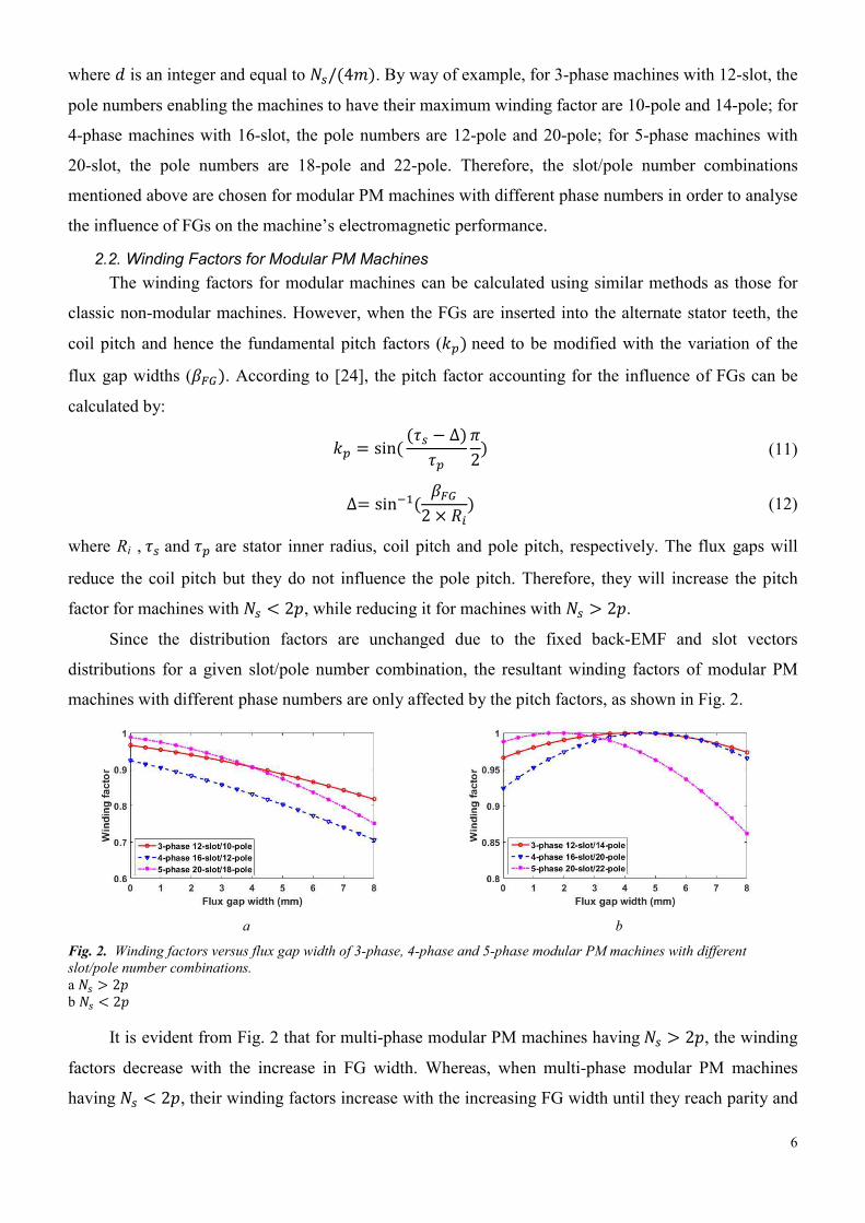
Fig. 2. Winding factors versus flux gap width of 3-phase, 4-phase and 5-phase modular PM machines with different slot/pole number combinations. a 軽鎚 伴 に喧 b 軽鎚 隼 に喧
It is evident from Fig. 2 that for multi-phase modular PM machines having 軽鎚 伴 に喧, the winding
factors decrease with the increase in FG width. Whereas, when multi-phase modular PM machines
having 軽鎚 隼 に喧, their winding factors increase with the increasing FG width until they reach parity and

7
subsequently decrease. The winding factor largely determines the electromagnetic performance.
Therefore, the influence of FGs will also be reflected on the machine’s performance, and will be
investigated in the following sections.
3. Design of Modular PM Machines The cross sections of modular PM machines with different phase numbers are depicted in Fig. 1.
The rotors for all machines have surface-mounted, full arc permanent magnets although other rotor
topologies can be employed such as interior or inset permanent magnets. Furthermore, it is worth
mentioning that the total active tooth body width for the stator teeth with or without FGs is unchanged
for different FG widths, as shown in Fig. 1. This is to avoid heavy local magnetic saturation occurring
in the tooth bodies when large FGs are employed. Some of the general design parameters are exactly the
same for the modular PM machines having different slot/pole number combinations and phase numbers,
as shown in Table 2.
Some other design parameters are optimized individually in a certain sequence, eg. split-ratio
(ratio of stator inner diameter to stator outer diameter) ė tooth body width (拳痛長) ė stator yoke height
(月鎚槻岻. The optimized design parameters for each modular PM machine with a different phase number
are given in Table 3. It is worth mentioning that the stator outer diameter and active length of the 3, 4
and 5-phase modular PM machines are always the same during the optimization process.
Table 2 General design parameters of modular PM machines
Phase voltage (V) 36 Stack length (mm) 50 Rated torque (Nm) 5.5 Air-gap length (mm) 1 Rated speed (rpm) 400 Magnet thickness (mm) 3 Stator outer radius (mm) 50 Magnet remanence (T) 1.2 Filling factor 倦長 0.37 Number of turns per phase 132
Table 3 Optimized design parameters of modular PM machines for achieving similar output torque
Modular PM machines 膏鎚 拳痛長 (mm) 月鎚槻 (mm) 荊眺暢聴 (A)
3-phase 0.57 7.1 3.7 7.35 4-phase 0.61 5.9 2.7 4.83 5-phase 0.64 4.7 1.9 3.41
4. Electromagnetic Performance of Modular PM Machines 4.1. Armature Magneto-Motive Force (MMF)
Although the fractional slot single-layer concentrated winding has advantages as mentioned above,
the inherent drawbacks of such a winding layout cannot be overlooked. By way of example, the rich
sub-harmonics in the armature MMF in the air-gap will result in many undesirable effects on the
performance of PM machines, such as increasing PM eddy current loss and core losses, heavy local
saturation, acoustic noise and vibrations, etc. Fortunately, the modular structure can help to effectively
mitigate those MMF sub-harmonics as will be demonstrated in this section.

8
The harmonics of armature MMF for modular PM machines having different slot/pole number
combinations and different phase numbers have been calculated. The results of the 3-phase, 4-phase and
5-phase machines are shown in Fig. 3. It has been established that the working (or fundamental)
harmonics are 5th or 7th order harmonics depending on slot/pole number combination for 3-phase, 6th or
10th for 4-phase, and 9th or 11th for 5-phase machines. As shown in Fig. 3, when the flux gap width
changes, the variations of the working harmonics, which produce the electromagnetic torque, are similar
to those of the winding factors. This is mainly due to the fact that the working air-gap MMF is largely
determined by the winding factor.
a b
c Fig. 3. Spectra of armature MMF of modular SPM machines. a 3-phase modular PM machines b 4-phase modular PM machines c 5-phase modular PM machines
However, for 3-phase and 5-phase modular PM machines, the sub-harmonics are mainly
contributed by the 1st order harmonic, while for 4-phase modular PM machines the 2nd order harmonic
is the main sub-harmonic. It is evident that for all modular machines, regardless of slot/pole number
combination and phase number, the main sub-harmonics are significantly reduced when the FGs are
introduced into the alternate stator teeth. In order to understand the influence of FGs on the armature
MMF in air-gap of modular PM machines, it is necessary to separate the influence of FGs from that of
slot openings (SOs). This is because for the modular PM machines, the primary two factors that
influence the armature MMF in air-gap are the SOs and FGs, as can be described by (13). Here, the
corresponding non-modular PM machines with unequal teeth (UNET) are introduced, which can be

9
simply obtained by replacing the FGs (air) by iron. This gives an armature MMF component due to SOs
only (警警繋腸朝帳脹). As a result, the MMF due to FGs only can be obtained by using the resultant MMF
and subtracting the 警警繋腸朝帳脹. This is possible because, to calculate the armature MMF in the air-gap,
the PMs are removed and the magnetic saturation can be neglected due to the large air-gap length of the
surface mounted permanent magnet machine. 警警繋陳墜鳥通鎮銚追 噺 警警繋腸朝帳脹 髪 警警繋庁弔鎚 (13)
Fig. 4 depicts the MMF components (due to SOs, FGs and resultant MMF) of non-modular and
modular PM machines. For the latter, a 3-phase machine with 12-slot/10-pole and FG=2mm is shown as
an example. It is evident that the FGs significantly reduce the subharmonics while increasing the
working harmonics when the slot/pole number combination is properly selected. This is because the
subharmonic component caused by FGs is always negative while for certain working harmonics, eg. the
7th order, the component due to FGs can be positive.
a b
Fig. 4. Influence of FGs on the air-gap MMF of 3-phase modular PM machines. a Waveforms b Spectra
In order to further investigate the influence of FGs on the main air-gap MMF sub-harmonics, the
flux distribution due to armature currents for 3-phase, 4-phase non-modular and modular PM machines
are shown in Fig. 5. The 5-phase machines are not shown because its main subharmonic is similar to
that of 3-phase machines. As expected, the main armature MMF subharmonic for the 3-phase machine
is 2 poles, while for the 4-phase machines it is 4-poles regardless of whether the machines are modular
or not. However, when the modular structure is employed as shown in Fig. 5 (c) and (d), the FGs in the
stator teeth add extra equivalent air-gap length to the flux path of the main armature subharmonic MMF
compared to its non-modular counterparts [Fig. 5 (a) and (b)]. As a result, the main sub-harmonics of
air-gap MMF for modular PM machines with different phase numbers can be significantly reduced, as
shown in Fig. 3
10
a b
c d
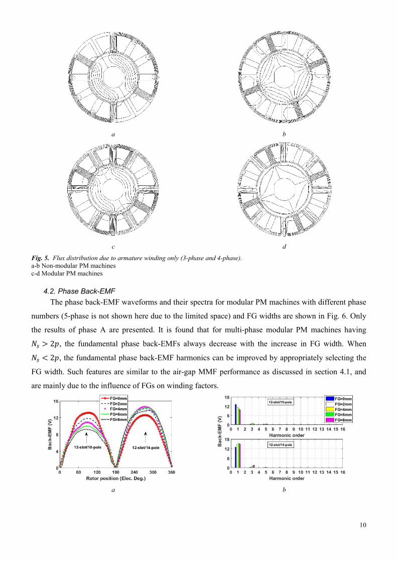
Fig. 5. Flux distribution due to armature winding only (3-phase and 4-phase). a-b Non-modular PM machines c-d Modular PM machines
4.2. Phase Back-EMF The phase back-EMF waveforms and their spectra for modular PM machines with different phase
numbers (5-phase is not shown here due to the limited space) and FG widths are shown in Fig. 6. Only
the results of phase A are presented. It is found that for multi-phase modular PM machines having 軽鎚 伴 に喧, the fundamental phase back-EMFs always decrease with the increase in FG width. When 軽鎚 隼 に喧, the fundamental phase back-EMF harmonics can be improved by appropriately selecting the
FG width. Such features are similar to the air-gap MMF performance as discussed in section 4.1, and
are mainly due to the influence of FGs on winding factors.
a b
11
c d
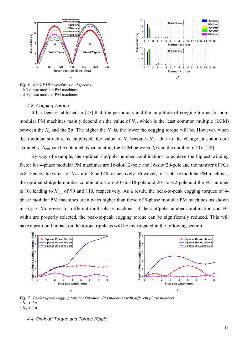
Fig. 6. Back-EMF waveforms and spectra. a-b 3-phase modular PM machines c-d 4-phase modular PM machines
4.3. Cogging Torque It has been established in [27] that, the periodicity and the amplitude of cogging torque for non-
modular PM machines mainly depend on the value of 軽頂, which is the least common multiple (LCM)
between the 軽鎚 and the に喧. The higher the Nc is, the lower the cogging torque will be. However, when
the modular structure is employed, the value of 軽頂 becomes 軽頂陳 due to the change in stator core
symmetry. 軽頂陳 can be obtained by calculating the LCM between に喧 and the number of FGs [28].
By way of example, the optimal slot/pole number combinations to achieve the highest winding
factor for 4-phase modular PM machines are 16-slot/12-pole and 16-slot/20-pole and the number of FGs
is 8. Hence, the values of 軽頂陳 are 48 and 40, respectively. However, for 5-phase modular PM machines,
the optimal slot/pole number combinations are 20-slot/18-pole and 20-slot/22-pole and the FG number
is 10, leading to 軽頂陳 of 90 and 110, respectively. As a result, the peak-to-peak cogging torques of 4-
phase modular PM machines are always higher than those of 5-phase modular PM machines, as shown
in Fig. 7. Moreover, for different multi-phase machines, if the slot/pole number combination and FG
width are properly selected, the peak-to-peak cogging torque can be significantly reduced. This will
have a profound impact on the torque ripple as will be investigated in the following section.
a b
Fig. 7. Peak-to-peak cogging torque of modular PM machines with different phase numbers. a 軽鎚 伴 に喧 b 軽鎚 隼 に喧
4.4. On-load Torque and Torque Ripple
12
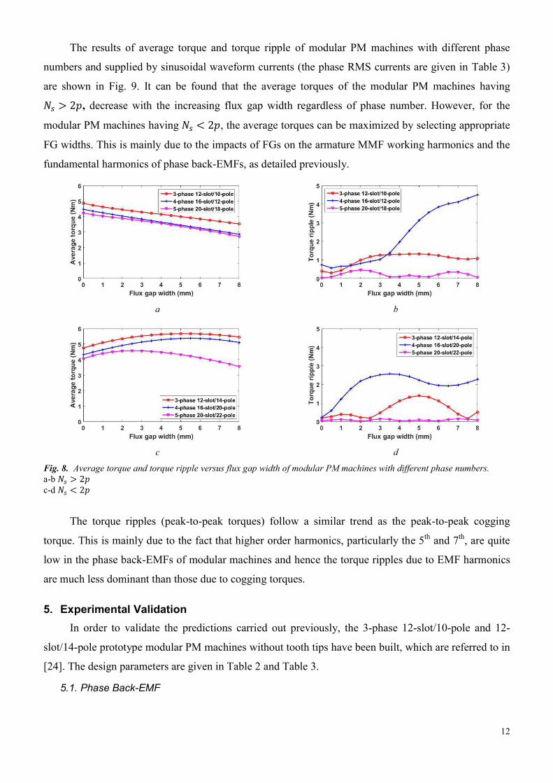
The results of average torque and torque ripple of modular PM machines with different phase
numbers and supplied by sinusoidal waveform currents (the phase RMS currents are given in Table 3)
are shown in Fig. 9. It can be found that the average torques of the modular PM machines having 軽鎚 伴 に喧, decrease with the increasing flux gap width regardless of phase number. However, for the
modular PM machines having 軽鎚 隼 に喧, the average torques can be maximized by selecting appropriate
FG widths. This is mainly due to the impacts of FGs on the armature MMF working harmonics and the
fundamental harmonics of phase back-EMFs, as detailed previously.
a b
c d
Fig. 8. Average torque and torque ripple versus flux gap width of modular PM machines with different phase numbers. a-b 軽鎚 伴 に喧 c-d 軽鎚 隼 に喧
The torque ripples (peak-to-peak torques) follow a similar trend as the peak-to-peak cogging
torque. This is mainly due to the fact that higher order harmonics, particularly the 5th and 7th, are quite
low in the phase back-EMFs of modular machines and hence the torque ripples due to EMF harmonics
are much less dominant than those due to cogging torques.
5. Experimental Validation In order to validate the predictions carried out previously, the 3-phase 12-slot/10-pole and 12-
slot/14-pole prototype modular PM machines without tooth tips have been built, which are referred to in
[24]. The design parameters are given in Table 2 and Table 3.
5.1. Phase Back-EMF

13
The phase back-EMFs of the prototypes are measured and compared with the corresponding
predicted results, as shown in Fig. 9. A good match can be obtained between the predicted and
measured results.
a b
c
Fig. 9. Predicted and measured phase back-EMFs. a 12-slot/10-pole b 12-slot/14-pole c Spectra of phase A as an example
5.2. Static Torque The static torque against the rotor position can be measured by employing the method presented
in [29] and the test rig is shown in Fig. 10 (a). The supply currents to phases A (荊凋岻, B (荊喋岻 and C (荊寵岻
are set as 荊凋 噺 伐荊喋【に 噺 伐荊寵【に 噺 荊, where 荊 is a DC and can be changed to represent different load
conditions. It is evident from Fig. 10 (b) that the predicted and measured results are in good agreement
for all prototype machines.
a b
Fig. 10. Static torque measurement (I=5A). a The prototype machines and the test rig b Static torque versus rotor position

14
6. Conclusion Multi-phase modular PM machines with single-layer concentrated windings were investigated in
this paper. The optimal slot/pole number combinations for modular PM machines with different phase
numbers were identified. The electromagnetic performance such as winding factors, air-gap MMF,
back-EMF, cogging torque, average torque and torque ripple have been investigated, it demonstrated
that:
The main sub-harmonics of air-gap MMF are significantly reduced by employing the modular
topologies for multi-phase PM machines. This can largely mitigate the negative effects on the
electromagnetic performance due to such sub-harmonics.
For multi-phase modular PM machines having 軽鎚 伴 に喧, the FGs have negative effects on the
electromagnetic performance such as decreasing the winding factors, MMF working harmonics
and average torques, etc.
For the multi-phase modular PM machines having 軽鎚 隼 に喧, if the flux gap width is properly
selected, the FGs can improve the electromagnetic performance, such as increasing average
torques and reducing the torque ripples.
The predictions obtained by FE have been validated by the experiments. The general rules
established in this paper summarized the influence of FGs on the electromagnetic performance of multi-
phase modular PM machines. Although only three, four and five-phase cases are discussed, the
conclusions achieved in this paper can be extended to modular PM machines with all other phase
numbers and can be used as design guidelines for multi-phase modular PM machines in practical
applications. Further, although only small size machines have been investigated in this paper for the
experimental validation purpose, the established general rules can be extended to the design and
analysis of large PM machines, eg. offshore wind generators.
7. Reference [1] Wang, J., Patel, V. I., and Wang, W., 'Fractional-slot permanent magnet brushless machines with low space
harmonic contents', IEEE Trans. Magn., 2014, 50, (1), pp. 1-9. [2] Zhu, Z. Q. and Howe, D., 'Electrical machines and drives for electric, hybrid, and fuel cell vehicles', Proc. IEEE,
Apr. 2007, 95, (4), pp. 746-765. [3] Bekka, N., Zaim, M. E., Bernard, N., et al., 'Optimization of the MMF function of fractional slot concentrated
windings', Proc. 2014 Int. Conf. Electr. Mach. (ICEM), Berlin, Germany, Sep. 2014, pp. 616-622. [4] Bianchi, N. and Pre, M. D., 'Use of the star of slots in designing fractional-slot single-layer synchronous motors',
IEE Proc. Elec. Power Appl., May. 2006, 153, (3), pp. 459-466. [5] Apsley, J. M., Williamson, S., Smith, A. C., et al., 'Induction motor performance as a function of phase number',
IEE Proc. Elec. Power Appl., Nov. 2006, 153, (6), p. 1. [6] Klingshirn, E. A., 'High phase order induction motors-Part I-Description and theoretical considerations', IEEE
Trans. Power Apparatus Syst., 1983, PAS-102, (1), pp. 47-53. [7] Refaie, A. M. E.-., Shah, M. R., Qu, R., et al., 'Effect of number of phases on losses in conducting sleeves of
surface PM machine rotors equipped with fractional-slot concentrated windings', IEEE Trans. Ind. Appl., 2008, 44, (5), pp. 1522-1532.
[8] Parsa, L. and Toliyat, H. A., 'Multi-phase permanent magnet motor drives', Proc. 38th Ind. Appl. Conf. (IAS) Annu. Meeting, Oct., 2003, 1, pp. 401-408.
[9] Parsa, L., Toliyat, H. A., and Goodarzi, A., 'Five-phase interior permanent-magnet motors with low torque pulsation', IEEE Trans. Ind. Appl., 2007, 43, (1), pp. 40-46.

15
[10] Sadeghi, S., Guo, L., Toliyat, H. A., et al., 'Wide operational speed range of five-phase permanent magnet machines by using different stator winding configurations', IEEE Trans. Ind. Electron., 2012, 59, (6), pp. 2621-2631.
[11] Toliyat, H. A., Waikar, S. P., and Lipo, T. A., 'Analysis and simulation of five-phase synchronous reluctance machines including third harmonic of airgap MMF', IEEE Trans. Ind. Appl., 1998, 34, (2), pp. 332-339.
[12] Huilin, K., Zhou, L., and Wang, J., 'Harmonic winding factors and MMF analysis for five-phase fractional-slot concentrated winding PMSM', Proc. 2013 Int. Conf. Electr. Mach. Syst. (ICEMS), Busan, South Korea, Oct. 2013., pp. 1236-1241.
[13] Barcaro, M., Bianchi, N., and Magnussen, F., 'Six-phase supply feasibility using a PM fractional-slot dual winding machine', IEEE Trans. Ind. Appl., 2011, 47, (5), pp. 2042-2050.
[14] Abdel-Khalik, A. S., Ahmed, S., and Massoud, A. M., 'A six-phase 24-slot/10-pole permanent-magnet machine with low space harmonics for electric vehicle applications', IEEE Trans. Magn., 2016, 52, (6), pp. 1-10.
[15] Patel, V. I., Wang, J., Wang, W., et al., 'Six-phase fractional-slot-per-pole-per-phase permanent-magnet machines with low space harmonics for electric vehicle application', IEEE Trans. Ind. Appl., 2014, 50, (4), pp. 2554-2563.
[16] Barcaro, M., Bianchi, N., and Magnussen, F., 'Analysis and tests of a dual three-phase 12-slot 10-pole permanent-magnet motor', IEEE Trans. Ind. Appl., 2010, 46, (6), pp. 2355-2362.
[17] Demir, Y. and Aydin, M., 'A novel dual three-phase permanent magnet synchronous motor with asymmetric stator winding', IEEE Trans. Magn., 2016, 52, (7), pp. 1-1.
[18] Zhu, Z. Q., Azar, Z., and Ombach, G., 'Influence of additional air gaps between stator segments on cogging torque of permanent-magnet machines having modular stators', IEEE Trans. Magn., 2012 48, (6), pp. 2049-2055.
[19] Bickel, B., Franke, J., and Albrecht, T., 'Manufacturing cell for winding and assembling a segmented stator of PM-synchronous machines for hybrid vehicles', Proc. 2012 2nd. Int. Elec. Drives Production Conf. (EDPC), Nuremberg, Germany, Oct. 2012, pp. 1-5.
[20] Nollau, A. and Gerling, D., 'Novel cooling methods using flux-barriers', Proc. Int. Conf. Electr. Mach. (ICEM), Berling, Germany, Sep., 2014, pp. 1328-1333.
[21] Spooner, E., Williamson, A. C., and Catto, G., 'Modular design of permanent-magnet generators for wind turbines', IEE Proc. Elec. Power Appl., Sep. 1996, 143, (5), pp. 388-395.
[22] Dajaku, G. and Gerling, D., 'Low costs and high-efficiency electric machines', Proc. 2nd Int. EDPC, Nuremberg, Germany. Oct., 2012, pp. 1-7.
[23] Dajaku, G., Xie, W., and Gerling, D., 'Reduction of low space harmonics for the fractional slot concentrated windings using a novel stator design', IEEE Trans. Magn., 2014, 50, (5), pp. 1-12.
[24] Li, G. J., Zhu, Z. Q., Foster, M., et al., 'Comparative studies of modular and unequal tooth PM machines either with or without tooth tips', IEEE Trans. Magn., 2014, 50, (7), pp. 1-10.
[25] Li, G. J., Zhu, Z. Q., Chu, W. Q., et al., 'Influence of flux gaps on electromagnetic performance of novel modular PM machines', IEEE Trans. Energy Convers., 2014, 29, (3), pp. 716-726.
[26] Bianchi, N., Pre, M. D., and Alberti, L., 'Theory and design of fractional-slot PM machines', (CLEUP Press, 2007). [27] Zhu, Z. Q., Ruangsinchaiwanich, S., and Howe, D., 'Synthesis of cogging-torque waveform from analysis of a
single stator slot', IEEE Trans. Ind. Appl., 2006, 42, (3), pp. 650-657. [28] Li, G. J., Ren, B., Zhu, Z. Q., et al., 'Cogging torque mitigation of modular permanent magnet machines', IEEE
Trans. Magn., 2016, 52, (1), pp. 1-10. [29] Zhu, Z. Q., 'A simple method for measuring cogging torque in permanent magnet machines', Proc. IEEE Power &
Energy Soc. General Meet., Calgary, Canada. Jul., 2009, pp. 1-4.