design and study of a lox/gh2 throttleable swirl injector
TRANSCRIPT
r
w •
Design and Study of a LOX/GH2 Throttleable Swirl Injector for Rocket Applications
Christopher Greene, Roger Woodward, Sibtosh Pal, and Robert SantoroPropulsion Engineering Research Center
Department of Mechanical and Nuclear EngineeringThe Pennsylvania State University
University Park, PA 16802
ABSTRACT
A LOX/GH2 swirl injector was designed for a 10:1 propellant throttling range. To accomplish this, a dualLOX manifold was used feeding a single common vortex chamber of the swirl element. Hot-fire experiments wereconducting for rocket chamber pressures from 80 to 800 psia at a mixture ratio of nominally 6.0 using steady flow,single-point-per-firing cases as well as dynamic throttling conditions. Low frequency (mean) and high frequency(fluctuating) pressure transducer data, flow meter measurements, and Raman spectroscopy images for mixinginformation were obtained. The injector design, experimental setup, low frequency pressure data, and injectorperformance analysis will be presented. C* efficiency was very high (-100%) at the middle of the throttleablerange with somewhat lower performance at the high and low ends. From the analysis of discreet steady stateoperating conditions, injector pressure drop was slightly higher than predicted with an inviscid analysis, butotherwise agreed well across the design throttling range. Analysis of the dynamic throttling data indicates that theinjector may experience transient conditions that effect pressure drop and performance when compared to steadystate results.
INTRODUCTION
With the latest drive by NASA and the industry to reduce costs for access to space, future vehicle designsare moving towards reduced number of stages and engines. This requires liquid rocket engines (LRE) to reducethrust to maintain optimum acceleration for an entire orbital insertion. Future vehicle concepts may even have themain engine provide thrust for final orbital insertion, atmospheric reentry, and landing. Also, rocket-basedcombined cycle propulsion, with a potential for reusability with little turnaround time between flights, is intenselybeing researched at this time. The LRE of the future will be required to provide more efficient thrust, performlonger, and operate across a wider throttling range.
Current liquid rocket engines rarely have been designed beyond a 2:1 throttling range. Huge penaltiesdue to nonlinear pressure drop increases with propellant flowrate result when designing a throttleable LRE withtoday's prevailing designs. This investigation sought to demonstrate an injector capable of deep (o 5:1) throttlingwithout unreasonable pressure drop penalties and without the use of moving parts in the injector.
Research Objectives
The objectives for this research program are as follows:• Design a swirl injector for LOX/GH2 for a mixture ratio of 6 and a throttleable chamber pressure range
goal of 10:1 (from 1000 to 100 psi).• Conduct hot-fire experiments to characterize the performance of the injector across the throttleable
range.• Evaluate the following:
o Uni-element C" efficiency over the throttleable range.o Uni-element chamber combustion stability with the injector over the throttleable range
(not presented in this paper, see Final Report1).o Uni-element mixing over the throttleable range at one chamber axial location using
Raman spectroscopy (not presented in this paper, see Final Report1).
Approved for public release, distribution is unlimited.
r
Research Approach
The concept of a 10:1 throttleable swirl injector was originally created during the tenure of guestresearcher Professor Viadimir Bazarov from Moscow Aviation Institute in Russia. Professor Bazarov's conceptualdesigns for throttling liquid-liquid injectors were modified and sized for a 10:1 throttling LOX/GH2 injector. Acompletely new injector assembly and manifold were created for the existing PSU two-inch square, windowedcombustion chamber. To conduct these experiments across the full throttling range, a LOX/LN2 heat exchangerwas also designed and installed just upstream of the injector to provide better quality LOX, particularly for lowflowrate conditions (< 0.3 Ibm/s).
The first phase of this program was to obtain steady state, single point case conditions across thethrottling range. During these steady state tests, the injector was characterized for pressure drop, combustionefficiency, and stability. To evaluate mixing in-situ, Raman spectroscopy data was acquired. The second phaseinvolved adding a continuous throttling capability to the Cryogenic Combustion Laboratory so that propellantflowrate could be varied during a single run. The purpose of this was to verify the throttling capabilities of thisinjector under more realistic dynamic conditions. Raman spectroscopy data were not acquired during thedynamic throttling experiments.
THROTTLEABLE INJECTOR DEVELOPMENT FOR LOX/GH2
The goal for this research was to design a throttleable injector using LOX/GH2 with a throttleable range of10:1. The design criteria for this throttleable injector were as follows:
• Mixture ratio of LOX to GH2 of six (O/F = 6).• LOX mass flow rate from 0.1 to 1.0 Ibm/s. GH2 mass flow rate from 0.0167 to 0.167 Ibm/s.
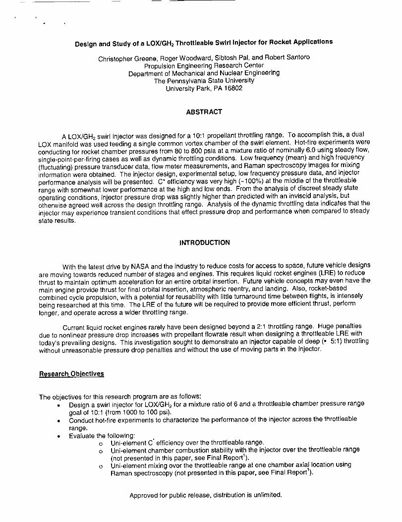
• Chamber pressure from 1000 down to 100 psia.• Pressure drop for LOX across the injector following the profile in Figure 1 where TA is the total inlet area
of the injector.
1
0.9
0.8
I_. ITAJ3(Angle=81,C0.7
J_ 0.6
"_ 0.5 LOX Manifold If I
t'_ 0.3 Single
,=0.2
0.1O.
0
0 200 400 600 800 1000
Chamber Pressure (psia)
Figure 1: LOX swirl injector pressure drop characteristics for single and dual LOX manifold operation.
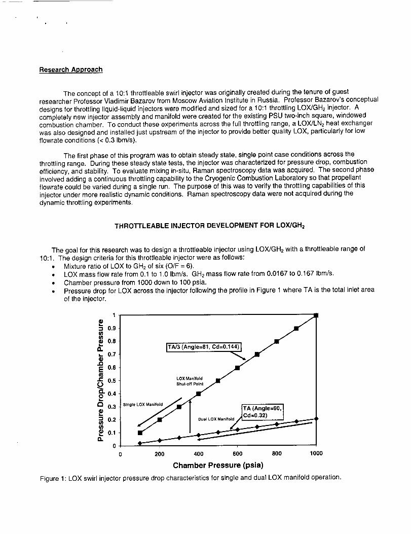
There are three key parameters a designer can manipulate in a tangential orifice swirl injector to obtainthe desired swirl characteristics of spray angle, pressure drop, and discharge coefficient 2a,4,s.These parametersare the inlet area (governed by ro and i, the number of inlets), the swirl chamber radius (R), and the nozzle exitradius (rc) as shown in Fi lure 2.
Figure 2: A Generic, tangential orifice swirl injector with inlet passage radius (ro), swirl chamber radius (R), and
nozzle exit radius (rc).
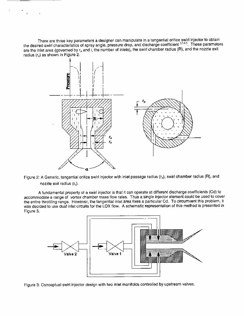
A fundamental property of a swirl injector is that it can operate at different discharge coefficients (Cd) toaccommodate a range of vortex chamber mass flow rates. Thus a single injector element could be used to coverthe entire throttling range. However, the tangential inlet area fixes a particular Cd. To circumvent this problem, itwas decided to use dual inlet circuits for the LOX flow. A schematic representation of this method is presented inFigure 3.
Valve 2
Figure 3: Conceptual swirl injector design with two inlet manifolds controlled by upstream valves.
Athighthrottle,Valves1and2 areopen.Ataprescribedlowthrottleposition(e.g.,350psiainFigure1),Valve2closes,decreasingthetangentialorificeinletareaandhencemassflow,causingachangein theswirlflowwitha lowerdischargecoefficient.Notethatitwasonlynecessaryto designa dualcircuitelementforLOXsincethefuelenterstheinjectorasa gas.TheAP/Pc for a gaseous injector is essentially constant with throttlingbecause the density changes proportionally with pressure 6. Therefore, only the LOX swirl element utilized thevalve manipulation of its inlet area. Although not necessary for throttling capability, an effort was made to alsoinvestigate a coaxially swirled gaseous hydrogen element to gain insight into the effect of swirled versus un-swirled coaxial GH2 on swirled LOX atomization.
Liquid Oxygen (Lox) Inlector Element
The first step to designing this injector was to find the necessary inlet area for the two LOX stages. Onerequirement was that at the minimum throttle condition, the pressure drop across the injector should not fall belowabout 8% of the chamber pressure to maintain low frequency stability margin. Another was that at the full-throttlepoint, the pressure drop across the injector should not exceed 20% of the chamber pressure to keep pumprequirements manageable.
To establish the correct effective inlet area of the injector for approximating the throttling profile in Figure1, the low throttle condition, when only LOX Manifold 1 is in operation, needed approximately a third of the totaleffective inlet area (TA/3). When both manifolds are open at the high throttle condition, the total effective inletarea (TA) is obtained. Therefore, the LOX injector element inlet orifices fed by LOX Manifold 2 had to haveapproximately twice the inlet area as the inlet orifices fed by LOX Manifold 1.
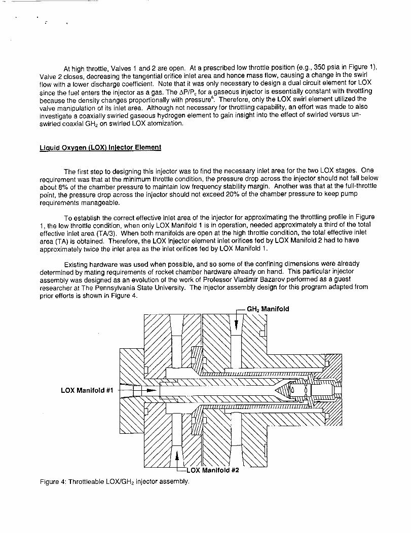
Existing hardware was used when possible, and so some of the confining dimensions were alreadydetermined by mating requirements of rocket chamber hardware already on hand. This particular injectorassembly was designed as an evolution of the work of Professor Vladimir Bazarov performed as a guestresearcher at The Pennsylvania State University. The injector assembly design for this program adapted fromprior efforts is shown in Figure 4.
LOX Manifold #1
//
////j _'/
/ ////f -LqV'OXManifold #2
Figure 4: Throttleable LOX/GH2 injector assembly.
GH2 Manifold
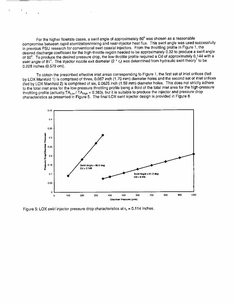
For the higher flowrate cases, a swirl angle of approximately 60° was chosen as a reasonablecompromise between rapid atomization/mixing and near-injector heat flux. This swirl angle was used successfullyin previous PSU research for conventional swirl coaxial injectors. From the throttling profile in Figure 1, thedesired discharge coefficient for the high-throttle region needed to be approximately 0.32 to produce a swirl angleof 60°. To produce the desired pressure drop, the low-throttle profile required a Cd of approximately 0.144 with aswirl angle of 81°. The injector nozzle exit diameter (2 * rc) was determined from hydraulic swirl theory 1 to be0.228 inches (0.579 cm).
To obtain the prescribed effective inlet areas corresponding to Figure 1, the first set of inlet orifices (fedby LOX Manifold 1) is comprised of three, 0.067 inch (1.70 mm) diameter holes and the second set of inlet orifices(fed by LOX Manifold 2) is comprised of six, 0.0625 inch (1.59 mm) diameter holes. This does not strictly adhereto the total inlet area for the low-pressure throttling profile being a third of the total inlet area for the high-pressurethrottling profile (actually,TAto,,/TAH_, = 0.383), but it is suitable to produce the injector and pressure dropcharacteristics as presented in Figure 5. The final LOX swirl injector design is provided in Figure 6.
0.45
0.4
0.35
0.3
0.25
0.2L.o
,_ 0.15
0.1
0.05
_" . _ Swirl Angle : 61.3 deg
"v" _ Cd =0.306
100 200 300 400 500 600 700 800
Chamber Pressure (psla}
90O IOO0
Figure 5: LOX swirl injector pressure drop characteristics at rc = 0.114 inches.
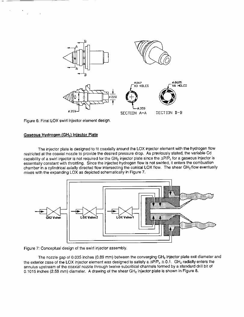
Figure 6: Final LOX swirl injector element design.
¢,.067 ,16,0625
,359
SECT[FIN A-A SECT]BN B-B
Gaseous Hydrogen (GHz) Inlector Plate
The injector plate is designed to fit coaxially around the LOX injector element with the hydrogen flowrestricted at the coaxial nozzle to provide the desired pressure drop. As previously stated, the variable Cd
capability of a swirl injector is not required for the GH2 injector plate since the AP/Pc for a gaseous injector isessentially constant with throttling. Since the injected hydrogen flow is not swirled, it enters the combustion
chamber in a cylindrical axially directed flow intersecting the conical LOX flow. The shear GH2 flow eventuallymixes with the expanding LOX as depicted schematically in Figure 7.
GH2 Val_
I
LOX Valve2
Figure 7: Conceptual design of the swirl injector assembly.
The nozzle gap of 0.035 inches (0.89 mm) between the converging GH2 injector plate exit diameter and
the exterior case of the LOX injector element was designed to satisfy a ,&P/Pc -= 0.1. GH2 radially enters theannulus upstream of the coaxial nozzle through twelve subcritical channels formed by a standard drill bit of0.1015 inches (2.58 mm) diameter. A drawing of the shear GH2 injector plate is shown in Figure 8.
_= e,1OE5
_x tJ" HOLg_
_CTIONA-A
A
---T¢_,&&7 - +--- 0.4_0
k
.U 7"',_ _
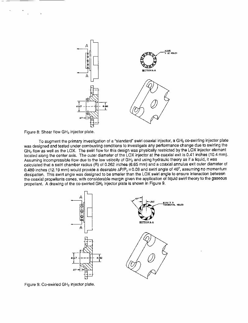
Figure 8: Shear flow GH2 injector plate.
To augment the primary investigation of a "standard" swirl coaxial injector, a GH2 co-swirling injector platewas designed and tested under combusting conditions to investigate any performance change due to swirling theGH2 flow as well as the LOX. The swirl flow for this design was physically restricted by the LOX injector elementlocated along the center axis. The outer diameter of the LOX injector at the coaxial exit is 0.41 inches (10.4 mm).Assuming incompressible flow due to the low velocity of GH2 and using hydraulic theory as if a liquid, it wascalculated that a swirl chamber radius (R) of 0.262 inches (6.65 mm) and a coaxial annulus exit outer diameter of0.480 inches (12.19 mm) would provide a desirable AP/Pc = 0.09 and swirl angle of 40 °, assuming no momentumdissipation. This swirl angle was designed to be smaller than the LOX swirl angle to ensure interaction betweenthe coaxial propellants cones, with considerable margin given the application of liquid swirl theory to the gaseouspropellant. A drawing of the co-swirled GH2 injector plate is shown in Figure 9.
3.A
A_r
F
_--_F_,_67 ___=_o
plate.Figure 9: Co-swirled GH2 injector
_.t44 X 9
T_N GE]_T]AL HrlI..IE_
_CTIONA-A
EXPERIMENTAL SETUP
The Facility
Hot-fire experimentation was performed at the Propulsion Engineering Research Center's CryogenicLaboratory at The Pennsylvania State University. This facility has the capacity to supply up to 1 Ibm/s (0.45 kg/s)of LOX from a high-pressure run tank. Gaseous hydrogen is supplied from K-bottle clusters providing up to 0.25Ibm/s (0.11 kg/s) at 2400 psia supply pressure. Along with LOX and GH2, the facility is also capable of supplyinghydrocarbon fuel such as RP, JP, and ethanol. The facility is composed of a reinforced concrete test cell with twotest stands, one on the ground floor and one on an upper tier, both run by a single control center. Currently, theupper test stand is configured for RBCC rocket/ejector studies and the lower for conventional rocket combustionstudies like this particular project.
Test Matrix
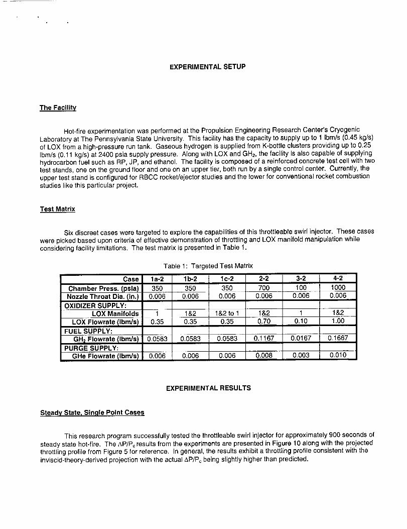
Six discreet cases were targeted to explore the capabilities of this throttleable swirl injector. These caseswere picked based upon criteria of effective demonstration of throttling and LOX manifold manipulation whileconsidering facility limitations. The test matrix is presented in Table 1.
Case
Chamber Press. (psia)Nozzle Throat Dia. (in.)
OXIDIZER SUPPLY:
Table 1" Targeted Test Matrix
la-2
3500.006
lb-2
35O0.006
lc-2
3500.006
2-2
7000.006
3-2
1000.006
4-21
10000.006
LOX Manifolds 1 1&2 1&2 to 1 1&2 1 1&2
LOX Flowrate tlbm/sl 0.35 0.35 0.35 0.70 0.10 1.00FUEL SUPPLY:
GH_ Flowrate libra/st 0.0583 0.0583 0.0583 0.1167 0.0167 0.1667PURGE SUPPLY:
GHe Flowrate (Ibm/s) 0.006 0.006 0.006 0.008 0.003 0.010
EXPERIMENTAL RESULTS
Steady State, Single Point Cases
This research program successfully tested the throttleable swirl injector for approximately 900 seconds ofsteady state hot-fire. The AP/Pc results from the experiments are presented in Figure 10 along with the projectedthrottling profile from Figure 5 for reference. In general, the results exhibit a throttling profile consistent with theinviscid-theory-derived projection with the actual AP/Pc being slightly higher than predicted.
0.45
0.4
0.35
I0.3
i0.25
0.2O
1
0.15
0.1
0.05
la-2CS
3-2 &[-2CS la 2-2CS ,._} 4-2CSi_ / Swirl Angle = 80.0 deg ,,,,.,.
l" / Cd=O'I4S lb2CS ,_'i_ "
i_ _ Swirl Angle = 61.3 deg
0 100 200 300 400 500 600 700 800 900
Chamber Pressure (psla)
1000
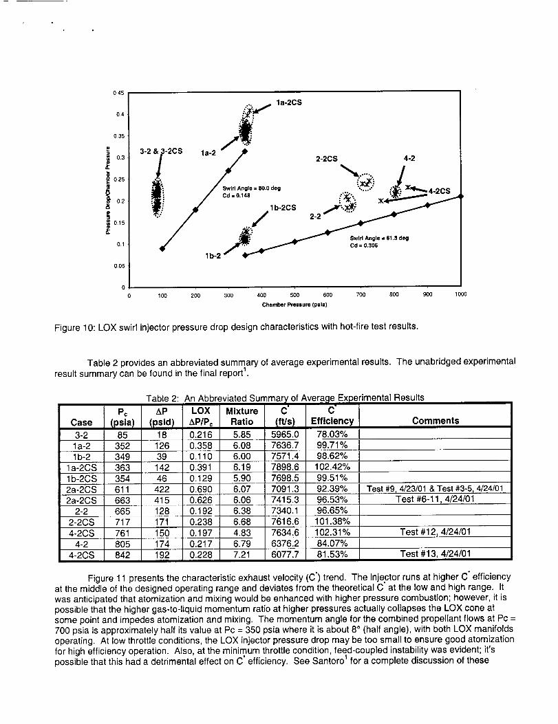
Figure 10: LOX swirl injector pressure drop design characteristics with hot-fire test results.
Table 2 provides an abbreviated summary of average experimental results. The unabridged experimental
result summary can be found in the final report 1.
Table 2: An Abbreviated
Pc AP LOX Mixture
Case Ipslal tpsidl AP/Pc Ratio3-2 85 18 0.216 5.851a-2 352 126 0.358 6.08
1b-2 349 39 0.110 6.00
la-2CS 363 142 0.391 6.19
1b-2CS 354 46 0.129 5.90
2a-2CS 611 422 0.690 6.07
2a-2CS 663 415 0.626 6.06
2-2 665 128 0.192 6.38
2-2CS 717 171 0.238 6.68
4-2CS 761 150 0.197 4.83
4-2 805 174 0.217 6.79
4-2CS 842 192 0.228 7.21
'of Avera£ }erimental Results
-clft/sl Efficiency Comments
5965.0 78.03%
7636.7 99.71%7571.4 98.62%
7898.6 102.42%
7698.5 99.51%
7091.3 92.39% Test #9, 4/23/01 & Test #3-5 r 4/24/017415.3 96.53% Test #6-11,4/24/01
7340.1 96.65%
7616.6 101.38%
7634.6 102.31% Test #12, 4/24/016376.2 84.07%
6077.7 81.53% Test #13, 4/24/01i
Figure 11 presents the characteristic exhaust velocity (C °) trend. The injector runs at higher C" efficiencyat the middle of the designed operating range and deviates from the theoretical C at the low and high range. It
was anticipated that atomization and mixing would be enhanced with higher pressure combustion; however, it ispossible that the higher gas-to-liquid momentum ratio at higher pressures actually collapses the LOX cone atsome point and impedes atomization and mixing. The momentum angle for the combined propellant flows at Pc =
700 psia is approximately half its value at Pc = 350 psia where it is about 8 ° (half angle), with both LOX manifoldsoperating. At low throttle conditions, the LOX injector pressure drop may be too small to ensure good atomization
for high efficiency operation. Also, at the minimum throttle condition, feed-coupled instability was evident; it'spossible that this had a detrimental effect on C ° efficiency. See Santoro 1 for a complete discussion of these
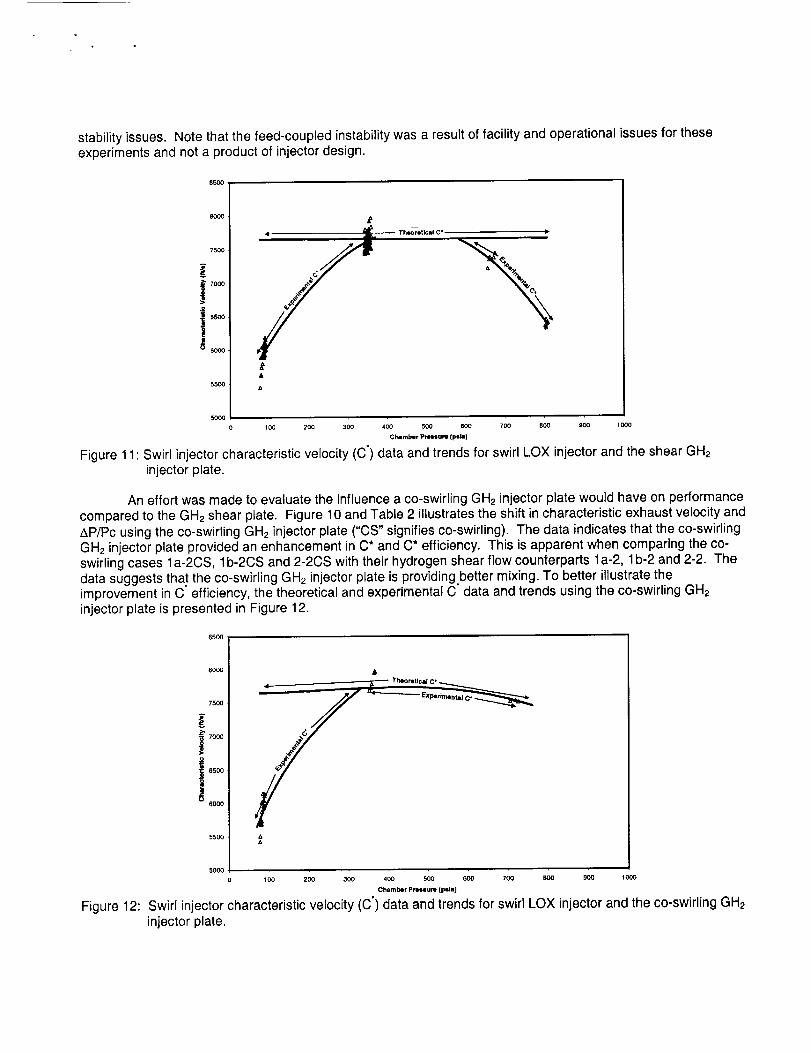
stability issues. Note that the feed-coupled instability was a result of facility and operational issues for theseexperiments and not a product of injector design.
85OO
8OO0
75OO
,_' 7000
i
soo0_
5OOO
0
Th_etlcsl C" I_
100 200 300 400 500 600 700 800 900 1000
Chamber Pro|su_ (psla)
Figure 11: Swirl injector characteristic velocity (C') data and trends for swirl LOX injector and the shear GHeinjector plate.
An effort was made to evaluate the influence a co-swirling GH2 injector plate would have on performancecompared to the GH2 shear plate. Figure 10 and Table 2 illustrates the shift in characteristic exhaust velocity and&P/Pc using the co-swirling GH2 injector plate ("CS" signifies co-swirling). The data indicates that the co-swirlingGH2 injector plate provided an enhancement in C* and C* efficiency. This is apparent when comparing the co-swirling cases la-2CS, lb-2CS and 2-2CS with their hydrogen shear flow counterparts la-2, 1b-2 and 2-2. Thedata suggests that the co-swirling GH2 injector plate is providingbetter mixing. To better illustrate theimprovement in C" efficiency, the theoretical and experimental C data and trends using the co-swirling GH2injector plate is presented in Figure 12.
85OO
Figure 12:
8OO0
75O0
70O0
I 6500
6OOO
55OO
5OOO
/100 200 300 400 500 600 700 BOO 900 1000
Chamber Pressure (psla)
Swirl injector characteristic velocity (C') data and trends for swirl LOX injector and the co-swirling GH2injector plate.
Dynamic Throttlinq
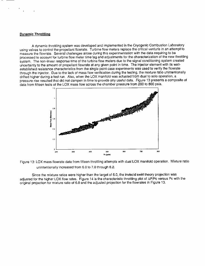
A dynamic throttling system was developed and implemented in the Cryogenic Combustion Laboratoryusing valves to control the propellant flowrate. Turbine flow meters replace the critical venturis in an attempt tomeasure the flowrate. Several challenges arose during this experimentation with the data requiring to beprocessed to account for turbine flow meter time lag and adjustments for the characterization of the new throttlingsystem. The non-linear response time of the turbine flow meters due to the signal conditioning system createduncertainty to the amount of propellant flowrate at any given point in time. The injector element with its well-established resistance characteristics from the single point case experiments was used to verify the flowratethrough the injector. Due to the lack of mass flow verification during the testing, the mixture ratio unintentionallydrifted higher during a test run. Also, when the LOX manifold was actuated from dual to solo operation, apressure rise resulted that did not dampen in time to provide any useful data. Figure 13 presents a composite ofdata from fifteen tests of the LOX mass flow across the chamber pressure from 200 to 800 psia.
110.8
!i200 300 400 500 600 700
Pc (psl=)
Figure 13: LOX mass flowrate data from fifteen throttling attempts with dual LOX manifold operation. Mixture ratio
unintentionally increased from 6.0 to 7.0 through 8.2.
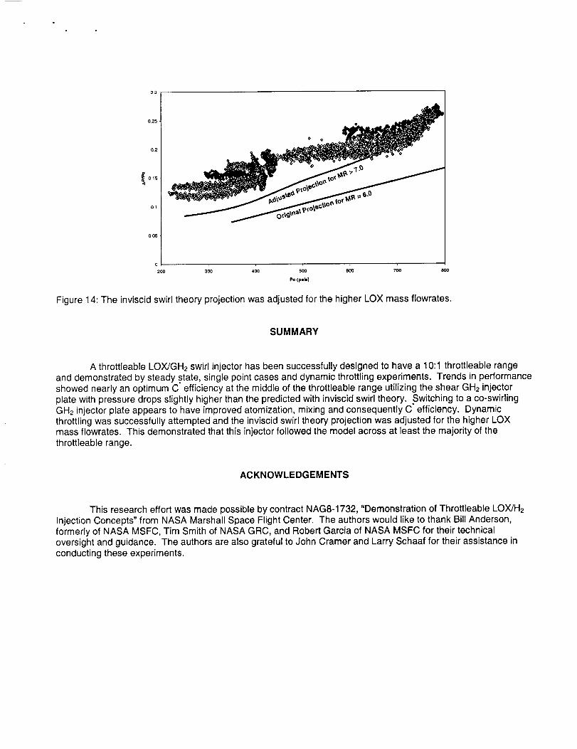
Since the mixture ratios were higher than the target of 6.0, the inviscid swirl theory projection wasadjusted for the higher LOX flow rates. Figure 14 is the characteristic throttling plot of AP/Pc versus Pc with theoriginal projection for mixture ratio of 6.0 and the adjusted projection for the flowrates in Figure 13.
03
025 t
• O
0.2 O O'
015
O01
200 30,0 400 500 600
P© (p=l=)
7oo 8OO
Figure 14: The inviscid swirl theory projection was adjusted for the higher LOX mass flowrates.
SUMMARY
A throttleable LOX/GH2 swirl injector has been successfully designed to have a 10:1 throttleable rangeand demonstrated by steady state, single point cases and dynamic throttling experiments. Trends in performanceshowed nearly an optimum C efficiency at the middle of the throttleable range utilizing the shear GH2 injectorplate with pressure drops slightly higher than the predicted with inviscid swirl theory. Switching to a co-swirlingGH2 injector plate appears to have improved atomization, mixing and consequently C efficiency. Dynamicthrottling was successfully attempted and the inviscid swirl theory projection was adjusted for the higher LOXmass flowrates. This demonstrated that this injector followed the model across at least the majority of thethrottleable range.
ACKNOWLEDGEMENTS
This research effort was made possible by contract NAG8-1732, "Demonstration of Throttleable LOX/H2Injection Concepts" from NASA Marshall Space Flight Center. The authors would like to thank Bill Anderson,formerly of NASA MSFC, Tim Smith of NASA GRC, and Robert Garcia of NASA MSFC for their technicaloversight and guidance. The authors are also grateful to John Cramer and Larry Schaaf for their assistance inconducting these experiments.
REFERENCE
i Santoro, R.J., Demonstration of LOX/GH z Throttleable Injector Studies, Final Report, Propulsion EngineeringResearch Center, The Pennsylvania State University, 2002.
2Doumas, M. and Laster R., "Liquid-Film Properties for Centrifugal Spray Nozzles," Chemical EnclineerinqPro,qress, Vol. 49, No. 10, pp. 519-526, October 1953.
3Bazarov, V. G., "Hydraulics of Swirl Propellant Injectors," Proceedings of the 9 th Annual PERC Symposium onPropulsion, Cleveland, OH, pp. 253-261, October 1-2, 1997.
4 Kulagin, L. V. and Okhotnikov, S. S., "Theory Of The Calculation of Single-Stage Centrifugal Atomizers",Combustion of Heavy Liquid Fuels, Translated by Foreign Technology Division, Air Force Systems Command,FTD-HT-23-927-68, pp. 162-180, 1967.
5 Bazarov V.G., ''Throttleable Liquid Propellant Engines Swirl Injectors for Deep Smooth Thrust Variations,"AIAA 94-2978, AIAA/SAE/ASME/ASEE 30t" Joint Propulsion Conference, Indianapolis, IN, June 27-29, 1994.
6 Limerick, C. D., "Component Design Concerns For Deep Throttling H2/O2 Rocket Engines," AIAA-91-2209-CP.