design and simulation of iron - steelmaking zero - · pdf filedesign and simulation of iron -...
TRANSCRIPT

Design and Simulation of Iron - Steelmaking Zero - Interface
LI Ming-yang1 Yan Yong-gang1 Lu Shao-wen2 Luo Zhi-guo2
Shandong Province Metallurgical Engineering Co.,Ltd., Jinan 250101, Shandong1,
China Dong Bei University, Shenyang 110004, Liaoning, china2
Email : [email protected]
Abstract
Base on profound study of different iron-steelmaking interface technology, designing a
high efficiency, environment friendly and low consumption iron-steelmaking interface
technology iron-steelmaking zero-interface technology and using computer simulation
technology test, the results show that the proposal of hot iron transport system of
iron-steelmaking zero-Interface technology is feasible.
Key words: One-ladle mode; iron-Steelmaking zero-interface; high efficiency ; energy
conservation and environmental protection; simulation
As technology flow to produce iron and steel advances, growing importance is being
attached to interface technology between steps. Particularly, the iron-steel interface
between blast furnace and SMS has moved forward quite fast recently as new
technologies, like locomotive carrying one ladle, electrical pallet carrying one ladle
emerges. The new technologies directly affect the transmission of matter, energy and
information flow between BF and SMS, associated with connecting, matching,
coordinating and stabilizing steps.
It explores various types of interface technologies and put forward a new type, that is
iron-steel zero interface, which primarily consists of advanced technology such as one
ladle, pallet direct delivery etc, covering BF production, hot metal transport,
pre-treatment, converter production etc, as well as relevant general layout.
Zero interface, or rather zero distance between BF and SMS, since there is no
obvious boundary in between. It is the ultimate of technology, where efficiency,
environment friendliness, energy saving features is all encompassing into one.

Existing hot metal transport pattern
Torpedo ladle car
Torpedo ladle car, as transport vehicle, receives hot metal from BF and takes it to
SMS, pours into converter hot metal mixing ladle, which is lifted up to pretreatment
station or charged into the converter. The equipment keeps it warm quite well, with
low gravity center and good safety. BF, usually is far away from SMS, providing an
enormous buffer space for good buffering. However, torpedo ladle must have one time
ladle to ladle work, which leads to temperature drop in hot metal and environment
pollution. Besides, ladle to ladle station would require dedusting device, calling for
tremendous investment and higher operating cost.
In China, conglomerate who uses above method includes: Bao Steel (300 t). An steel
(250 t), Wuhan Steel 3rd SMS (250 t) [1] etc.
Locomotive carrying one ladle transport (standard rail).
One ladle transport
One ladle straight to SMS, or rather one ladle system, has just come up as a new
interface technology. It uses converter mixing ladle to receive hot metal from BF cast
house, takes it to SMS for pretreatment or charges into converter. It removes ladle to
ladle step by hot metal ladle or torpedo ladle car in conventional process, and uses
SMS hot metal ladle for transport instead, benefitting there by due to energy saving,
environment friendliness, lower production cost, etc.
Locomotive carrying one ladle
This approach uses hot metal ladle as transport container, which receives hot metal
from BF, taken to SMS by diesel locomotive on rails with standard track gauge of
1435mm. With this way, BF can be arranged conventionally, but it would occupy
enormous land. And for large scale converter, it might present safety risk, due to large
size hot metal ladle, high gravity and narrow track gauge. Conglomerate that uses
above approach includes Shougang Steel Jingtang (300t).
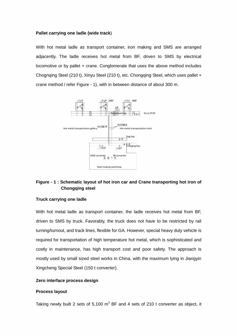
Pallet carrying one ladle (wide track)
With hot metal ladle as transport container, iron making and SMS are arranged
adjacently. The ladle receives hot metal from BF, driven to SMS by electrical
locomotive or by pallet + crane. Conglomerate that uses the above method includes
Chognqing Steel (210 t), Xinyu Steel (210 t), etc. Chongqing Steel, which uses pallet +
crane method / refer Figure - 1), with in between distance of about 300 m.
Figure - 1 : Schematic layout of hot iron car and Crane transporting hot iron of
Chongqing steel
Truck carrying one ladle
With hot metal ladle as transport container, the ladle receives hot metal from BF,
driven to SMS by truck. Favorably, the truck does not have to be restricted by rail
turning/turnout, and track lines, flexible for GA. However, special heavy duty vehicle is
required for transportation of high temperature hot metal, which is sophisticated and
costly in maintenance, has high transport cost and poor safety. The approach is
mostly used by small sized steel works in China, with the maximum lying in Jiangyin
Xingcheng Special Steel (150 t converter).
Zero interface process design
Process layout
Taking newly built 2 sets of 5,100 m3 BF and 4 sets of 210 t converter as object, it
Go to PCM
2#BF 1#BF
Desulphurizing
Steel making workshop
Hot metal transportation track Hot metal transportation gallery
1#2# converter
Charging bay
Slag bay
3# converter
examines hot metal transport technology with iron-steel zero interface.
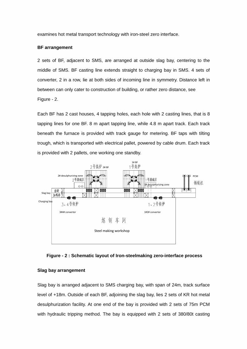
BF arrangement
2 sets of BF, adjacent to SMS, are arranged at outside slag bay, centering to the
middle of SMS. BF casting line extends straight to charging bay in SMS. 4 sets of
converter, 2 in a row, lie at both sides of incoming line in symmetry. Distance left in
between can only cater to construction of building, or rather zero distance, see
Figure - 2.
Each BF has 2 cast houses, 4 tapping holes, each hole with 2 casting lines, that is 8
tapping lines for one BF. 8 m apart tapping line, while 4.8 m apart track. Each track
beneath the furnace is provided with track gauge for metering. BF taps with tilting
trough, which is transported with electrical pallet, powered by cable drum. Each track
is provided with 2 pallets, one working one standby.
Figure - 2 : Schematic layout of Iron-steelmaking zero-interface process
Slag bay arrangement
Slag bay is arranged adjacent to SMS charging bay, with span of 24m, track surface
level of +18m. Outside of each BF, adjoining the slag bay, lies 2 sets of KR hot metal
desulphurization facility. At one end of the bay is provided with 2 sets of 75m PCM
with hydraulic tripping method. The bay is equipped with 2 sets of 380/80t casting
Slag bay
3#4# converter
Steel making workshop
1#2# converter
Charging bay
1# BF
2# BF
1# desulphurizing zone
PCM 2# desulphurizing zone
crane for lifting hot metal, with 2 sets of 125/40t casting crane for transfer slag. The
bay also has heavy pouring ground support, emergency hot metal pit etc.
Charging bay arrangement
The bay in SMS spans 24m. BF tapping line comes through slag bay into charging
bay. The bay is primarily provided with 4 sets of 380/80t casting crane for lifting and
charging into converter, with 2 sets of 75+75t overhead crane for charging scrap into
the converter. The scrap, having weighed on proportioning hopper in distribution
center, is sent into SMS from both ends of the bay with entire hopper. The bay is also
provided with heavy pouring ground support, hot metal ladle insulating heating device
etc.
Iron-steel zero interface running pattern
Process flow
Under normal circumstances, when certain tapping hole is about to tap, 2 electrical
pallets beneath the hole comes to position beforehand to be ready. Once it starts, the
ladle at one side receives the hot metal first and swing trough moves to the other one
lying at the other side, when the first one fills up. The full ladles are driven by the
pallets to slag bay, where they are taken up to desulphurization tripper car by
380 / 80 t casting crane, and taken for desulphurization pretreatment. Then the pallet
moves further forward to charging bay, and an empty ladle is laid on it, with new ladle
it returns to BF beneath for next tapping. When pretreatment is over, it is taken by hot
metal tripper car to SMS charging bay, and is lifted up by 380 / 80 t casting crane to
charge into the converter. The process goes on and on until tapping finishes off. If
desulphurization is not required, pallet can directly take hot metal ladle to charging
bay, which is taken away by the crane there, assigned with empty ladle and returns
back to BF for next tapping.
The last ladle from tapping, usually, has half of it, unfit for SMS, and can not directly
be used for steel making. It could remain beneath the furnace for next tapping, or be

taken to slag bay, where it is transferred by crane to next tapping hole for filling up
before returning for SMS.
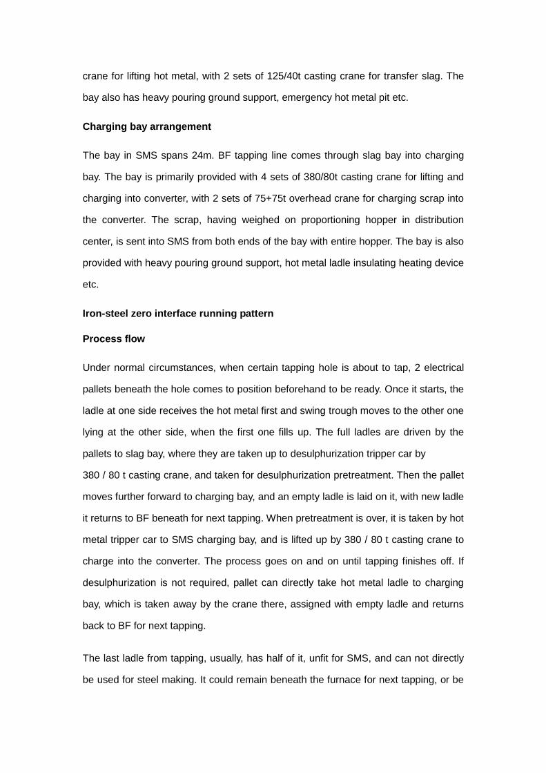
Figure - 3 below defects the Iron-steel zero interface hot metal transport process flow.
Figure - 3 : Process flow of hot iron transportation
BF tapping system
Newly built BF will have diagonal tapping system, or 3 iron runners rotate with one in
maintenance for standby. Tapping time is designed to be 10~12 times/day, speed
7~9 t/min (average speed 8t/min), tapping quantity of each ladle of 210 t, max 230 t,
control accuracy of ±1.0 t
Table - 1 BF tapping system
Item Design value Remarks
BF effective volume m3 5100
Average daily hot metal, t 11570
Tapping volume/time, t 964~1157
Tapping speed,t/min 7~9
Tapping time/d 10~12
Tapping duration/time 121~145
Tapping ladle /time 4.6~5.5
Tapping duration/ladle,
min
23.3~30 Average
26.25min
Tapping system Diagonal
台车 行车 加料跨
返回
台车
倾翻车 铁水 高炉
铁水罐
受铁 渣跨 脱硫
铁水倾
翻车 转炉
加料跨 台车配空罐 炉下
Pallet car Crane
Charging bay
Returns
Pallet car
Titling car Hot metal
BF Hot metal
ladle
receiving
Slag bay Desulphu
rizing
Hot metal
tilting car
Converter
Charging bay Pallet car+empty tank Under BF
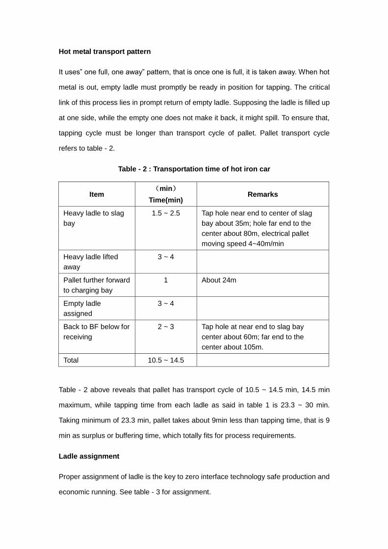
Hot metal transport pattern
It uses” one full, one away” pattern, that is once one is full, it is taken away. When hot
metal is out, empty ladle must promptly be ready in position for tapping. The critical
link of this process lies in prompt return of empty ladle. Supposing the ladle is filled up
at one side, while the empty one does not make it back, it might spill. To ensure that,
tapping cycle must be longer than transport cycle of pallet. Pallet transport cycle
refers to table - 2.
Table - 2 : Transportation time of hot iron car
Item (min)
Time(min) Remarks
Heavy ladle to slag
bay
1.5 ~ 2.5 Tap hole near end to center of slag
bay about 35m; hole far end to the
center about 80m, electrical pallet
moving speed 4~40m/min
Heavy ladle lifted
away
3 ~ 4
Pallet further forward
to charging bay
1 About 24m
Empty ladle
assigned
3 ~ 4
Back to BF below for
receiving
2 ~ 3 Tap hole at near end to slag bay
center about 60m; far end to the
center about 105m.
Total 10.5 ~ 14.5
Table - 2 above reveals that pallet has transport cycle of 10.5 ~ 14.5 min, 14.5 min
maximum, while tapping time from each ladle as said in table 1 is 23.3 ~ 30 min.
Taking minimum of 23.3 min, pallet takes about 9min less than tapping time, that is 9
min as surplus or buffering time, which totally fits for process requirements.
Ladle assignment
Proper assignment of ladle is the key to zero interface technology safe production and
economic running. See table - 3 for assignment.

Table - 3 ladle assignment
Item Design value Remarks
Receiving volume, t 211.5
Tapping ladle per day, ladle 109.4
Assignment pattern One ladle one away
Ladle cycle time, min 117
Cycle rate, time/d 12
No of hot cycle 10
On line cold ladle as standby, piece 16
Hot, cold repair and standby, piece 15
No of hot metal ladle, piece 41
Half ladle handling pattern Rotate to next time or
next tapping
Push into next
time tapping 3rd
ladle
Hot metal buffering facility
PCM, heavy ladle ground
support, hot metal
insulating device etc
Simulation
The feasibility is verified by simulating iron-steel zero interface to confirm that material
flow is running smooth, process viable, different links connecting or not, and that if
there is any unstable or uncertain risk factor.
Simulation parameter setting
Simulation parameter is set based on design and actual production parameters, see
table 4 for main values. Such parameters as converter smelting cycle, hot metal
pretreatment cycle etc are generated randomly as per normal distribution, with
reference to actual production. And other parameters are set according to design
value.
As to the last ladle, it is to be simulated as through it goes to the next tapping hole. It
has already held some amount of hot metal (to be restricted to < 30t), the 3rd ladle
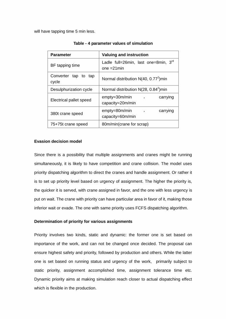
will have tapping time 5 min less.
Table - 4 parameter values of simulation
Parameter Valuing and instruction
BF tapping time Ladle full=26min, last one=8min, 3rd
one =21min
Converter tap to tap
cycle Normal distribution N(40, 0.772)min
Desulphurization cycle Normal distribution N(28, 0.842)min
Electrical pallet speed empty=30m/min , carrying
capacity=20m/min
380t crane speed empty=80m/min , carrying
capacity=60m/min
75+75t crane speed 80m/min(crane for scrap)
Evasion decision model
Since there is a possibility that multiple assignments and cranes might be running
simultaneously, it is likely to have competition and crane collision. The model uses
priority dispatching algorithm to direct the cranes and handle assignment. Or rather it
is to set up priority level based on urgency of assignment. The higher the priority is,
the quicker it is served, with crane assigned in favor, and the one with less urgency is
put on wait. The crane with priority can have particular area in favor of it, making those
inferior wait or evade. The one with same priority uses FCFS dispatching algorithm.
Determination of priority for various assignments
Priority involves two kinds, static and dynamic: the former one is set based on
importance of the work, and can not be changed once decided. The proposal can
ensure highest safety and priority, followed by production and others. While the latter
one is set based on running status and urgency of the work, primarily subject to
static priority, assignment accomplished time, assignment tolerance time etc.
Dynamic priority aims at making simulation reach closer to actual dispatching effect
which is flexible in the production.

Calculation formula for dynamic priority:
𝑓(t)= pt -qt+λi×Twait-ki×Trun+βj×Tnext
𝑓(t)stands for assignment dynamic priority
pt for static priority of current assignment
qt for static priority of following assignment
Twait for tolerance waiting time of current assignment
Trun for completion time of current assignment
Tnext for time till following assignment
λi for weight control parameter of 0~1 of waiting time
ki for weight control parameter of 0~1of running time
βj for weight control parameter of 0~1of waiting time for following assignment
The above definition takes into account the static priority of current assignment, and
virtually foresees the urgency of following assignment, so that the priority could be
determined in a comprehensive way.
Crane evasion and collision algorithm
To avoid disorganized competition and collision of cranes arranged at same zone, the
model uses virtual prediction and priority competition algorithm to evade possible
collision. Or rather, the right of engaging particular track at certain zones for cranes is
determined by current crane status and priorities. Virtual foreseeing is capable of
obtaining status of crane and track which might run in particular zone in the future,
which could be used as basis to make decision about evasion and collision.

Figure - 4 : Scheduling frame of collision avoidance of crane
Realization of simulation
Based on set simulated parameter, priority algorithm and evasion & collision model,
set up simulated model, using computer simulated software by windows to simulate,
referring to figure 4(only extracted part simulated interface from 2 # BF).
Figure - 5 : Interface of simulation system
Simulation result
According to production situation, following typical status are simulated: ①2 sets of BF
and 4 sets of converter running normally; ②1 set of converter shut-down for
maintenance, 2 sets of BF against 3 sets of converter under maintenance; ③ 2 sets of
converter under maintenance, 2 sets of BF against 2 sets of converter and PCM,
which is extreme emergency status; ④ 4 sets of converter all under phosphor removal
+ decarbonization duplex smelting status etc.
The result reveals that, apart from 2 sets of converter under emergency maintenance,
SMS and iron making running extraordinarily unbalanced, hot metal continuing to
4# taphole (standby)
3# converter
Scrap in bucket 4# converter
4# taphole (standby)
1# taphole
Charging bay 380t crane 3# utilization rate=42%
2#BF
current
BF tapping time
Desulphurizing bay 380t crane 1# utilization rate=0
Work condition 1(BF*2 pairs converter*4)
Charging bay 380t crane 4# utilization rate=55%
2# taphole
Desulphurizing bay 380t crane 2# utilization rate=35%
Current tapping=4
current
3# taphole
Full ladle=26mins 6
th ladle=8mins
Converter treatment time=40mins
3rd
ladle=21mins
Desulphurizing time=27mins
Overtime time=0

build up, calling for BF to reduce output by back draft, it could be running smoothly
under other situation. Over long time simulated running, nothing like empty ladle could
not return promptly has ever happened under any situation. One and all links connect,
match and run in a steady, proper and coordinated manner. It indicates that iron-steel
zero interface is reasonable and viable.
Conclusion
Iron-steel zero interface technology optimizes and revamp the hot metal transport flow,
taking off unnecessary links in between, simplifying process flow, and narrowing down
the distance. It is a new sort of iron-steel interface technology, energy saving,
environment friendly, high efficiency and simple. The technology cuts down
investment and running cost, land as well. Therefore, it should bear tremendous and
promising application. However, the disadvantages are that it is dependent more on
ladle tapping time, that tap to tap cycle must be worked out as per particular project
and that hot metal transport cycle should match. It is concluded that it should be
selected and used properly.
Reference
[1] Pan Yongfei, Chen Jinfeng, Zhang Jianguo, comparison of hot metal transportation
patter amongst large scale steel works, [J].BaoSteel technology ,2012, 4:55~56
[2] Ye Wei, Zou Zhongping, Su Li etc, One ladle process desing for hot metal
transportation in Chongqing Steel[J].iron making,2012, 31(2):22~23
[3] Luo Shouzhang, Qiu Hongping, Liu Feng, Model setting for crane dispatching and
simulation research of hot metal transportation system [J].Baosteel technology,
2004, 4:18~21
[4] Long De, Me Jianshi, Xu Xinhe, Smart simulation model of hot metal transportation
system, Journal of Southeastern university( natural science edition),2005, 26
(6):523~526
[5] Cui Jianjiang, Xu Xinhe, Research of simulation system for hot metal

transportation[R].System simulated technology and application,2002, 8:48~53